

Page 1

PowerEdge VRTX 1Gb Switch Module
R1-2401
User Guide
FILE LOCATION: C:\Users\gina\Desktop\Checkout_new\Dell Plasma\User
DELL CONFIDENTIAL – PRELIMINARY 4/18/13 – FOR PROOF ONLY
Regulatory Model: E12M
Regulatory Type: E12M001
Guide\Plasma_UGCover_56NT1.fm
Template Last Updated -03/06/2010
Page 2

FILE LOCATION: C:\Users\gina\Desktop\Checkout_new\Dell Plasma\User
Notes, Cautions, and Warnings
NOTE: A NOTE indicates important information that helps you make better use of
your computer.
CAUTION: A CAUTION indicates either potential damage to hardware, or loss of
data and tells you how to avoid the problem.
WARNING: A WARNING indicates a potential for property damage, personal
injury, or death.
____________________
Information in this publication is subject to change without notice.
© 2013 Dell Inc. All rights reserved.
Reproduction of these materials in any manner whatsoever without the written permission of Dell Inc.
is strictly forbidden.
Trademarks used in this text: Dell™, the DELL logo, Dell Precision™, OptiPlex™, Latitude™,
PowerEdge™, PowerVault™, PowerConnect™, OpenManage™, EqualLogic™, KACE™,
FlexAddress™ and Vostro™ are trademarks of Dell Inc. Intel, Pentium, Xeon, Core™ and Celero n
are registered trademarks of Intel Corporation in the U.S. and other countries. AMD is a registered
trademark and AMD Opteron™, AMD Phenom™, and AMD Sempron™ are trademarks of Advanced
Micro Devices, Inc. Microsoft
either trademarks or registered trademarks of Microsoft Corporation in the United States and/or other
countries. Red Hat Enterprise Linux
Inc. in the United States and/or other countries. Novell
trademark of Novell Inc. in the United States and other countries. Oracle
of Oracle Corporation and/or its affiliates. Citrix
registered trademarks or trademarks of Citrix Systems, Inc. in the United States and/or other countries.
®
VMware
trademarks of VMWare, Inc. in the United States or other countries.
Other trademarks and trade names may be used in this publication to refer to either the entities claiming
the marks and names or their products. Dell Inc. disclaims any proprietary interest in trademarks and
trade names other than its own.
, Virtual SMP®, vMotion®, vCenter®, and vSphere® are registered trademarks or
®
, Windows®, Windows Server®, MS-DOS® and Windows V ista® are
®
and Enterprise Linux® are registered trademarks of Red Hat,
®
is a registered trademark and SUSE ™ is a
®
, Xen®, XenServer® and XenMotion® are either
®
is a registered trademark
Regulatory Model: E12M
Regulatory Type: E12M001
April 2013 P/N 56NT1 Rev. A03
DELL CONFIDENTIAL – PRELIMINARY 4/18/13 – FOR PROOF ONLY
Page 3

FILE LOCATION: C:\Users\gina\Desktop\Checkout_new\Dell Plasma\User
Guide\Dell_PlasmaUG_PrintTOC.fm
Contents
1 Preface . . . . . . . . . . . . . . . . . . . . . . . . . . 11
2 Features. . . . . . . . . . . . . . . . . . . . . . . . . . 13
IP Version 6 (IPv6) Support . . . . . . . . . . . . . . . 14
Head of Line Blocking Prevention. . . . . . . . . . . . 14
Back Pressure Support
Virtual Cable Testing (VCT)
. . . . . . . . . . . . . . . . . 14
. . . . . . . . . . . . . . . 14
Auto-Negotiation . . . . . . . . . . . . . . . . . . . . 14
MDI/MDIX Support
MAC Address Supported Features
. . . . . . . . . . . . . . . . . . . . 15
. . . . . . . . . . . 15
Layer 2 Features . . . . . . . . . . . . . . . . . . . . . 16
IGMP Snooping
Port Mirroring
. . . . . . . . . . . . . . . . . . . . . 16
. . . . . . . . . . . . . . . . . . . . . . 17
Broadcast Storm Control . . . . . . . . . . . . . . . . 17
VLAN Supported Features
Spanning Tree Protocol Features
. . . . . . . . . . . . . . . . 17
. . . . . . . . . . . . 19
Link Aggregation. . . . . . . . . . . . . . . . . . . . . 20
Quality of Service Features
Device Management Features
. . . . . . . . . . . . . . . 21
. . . . . . . . . . . . . . 22
Contents
3
Page 4

FILE LOCATION: C:\Users\gina\Desktop\Checkout_new\Dell Plasma\User
Guide\Dell_PlasmaUG_PrintTOC.fm
Security Features . . . . . . . . . . . . . . . . . . . . 25
Port Profile (CLI Macro)
. . . . . . . . . . . . . . . . . 27
DHCP Server . . . . . . . . . . . . . . . . . . . . . . . 28
Protected Ports
Proprietary Protocol Filtering
. . . . . . . . . . . . . . . . . . . . . . 28
. . . . . . . . . . . . . . 28
3 Hardware and Initial Configuration . . . . 29
Switch Hardware . . . . . . . . . . . . . . . . . . . . 29
Initial Configuration of the Switch
. . . . . . . . . . . 32
4 Using the CLI . . . . . . . . . . . . . . . . . . . . . 35
Using the CLI . . . . . . . . . . . . . . . . . . . . . . . 35
CLI Command Conventions. . . . . . . . . . . . . . . . 38
Accessing the Device Through the CLI
Retrieving an IP Address
. . . . . . . . . . . . . . . . . 40
. . . . . . . . . 39
5 Network Administrator. . . . . . . . . . . . . . 53
4 Contents
Security Management and Password Configuration . . 42
Configuring Login Banners
Startup Menu Procedures
. . . . . . . . . . . . . . . 44
. . . . . . . . . . . . . . . . 46
Software Download . . . . . . . . . . . . . . . . . . . 48
Starting the Application . . . . . . . . . . . . . . . . . 53
Page 5

FILE LOCATION: C:\Users\gina\Desktop\Checkout_new\Dell Plasma\User
Guide\Dell_PlasmaUG_PrintTOC.fm
Understanding the Interface. . . . . . . . . . . . . . . 53
Using the Network Administrator Buttons
. . . . . . . 54
Field Definitions . . . . . . . . . . . . . . . . . . . . . 55
Common GUI Features
GUI Terms
. . . . . . . . . . . . . . . . . . . . . . . . 57
. . . . . . . . . . . . . . . . . . 56
6 Configuring System Information . . . . . . . 59
General Switch Information . . . . . . . . . . . . . . . 59
Time Synchronization
. . . . . . . . . . . . . . . . . . . . . . . . . . . 86
Logs
IP Addressing . . . . . . . . . . . . . . . . . . . . . . 98
Diagnostics
. . . . . . . . . . . . . . . . . . . . . . . 129
Management Security
SNMP . . . . . . . . . . . . . . . . . . . . . . . . . . 161
File Management
. . . . . . . . . . . . . . . . . . 64
. . . . . . . . . . . . . . . . . . 131
. . . . . . . . . . . . . . . . . . . . 182
7 Network Security . . . . . . . . . . . . . . . . . 203
Port Security . . . . . . . . . . . . . . . . . . . . . . . 203
ACLs . . . . . . . . . . . . . . . . . . . . . . . . . . . 206
ACL Binding
Proprietary Protocol Filtering
Time Range. . . . . . . . . . . . . . . . . . . . . . . . 225
. . . . . . . . . . . . . . . . . . . . . . . 222
. . . . . . . . . . . . . . 224
Contents
5
Page 6

FILE LOCATION: C:\Users\gina\Desktop\Checkout_new\Dell Plasma\User
Guide\Dell_PlasmaUG_PrintTOC.fm
Dot1x Authentication. . . . . . . . . . . . . . . . . . 228
8Ports. . . . . . . . . . . . . . . . . . . . . . . . . . . . 249
Overview . . . . . . . . . . . . . . . . . . . . . . . . 249
Jumbo Frames . . . . . . . . . . . . . . . . . . . . . 251
Green Ethernet Configuration
Protected Ports
. . . . . . . . . . . . . . . . . . . . 255
. . . . . . . . . . . . . 252
Port Profile . . . . . . . . . . . . . . . . . . . . . . . 257
Port Configuration
LAG Configuration
. . . . . . . . . . . . . . . . . . . 262
. . . . . . . . . . . . . . . . . . . 268
Storm Control . . . . . . . . . . . . . . . . . . . . . 271
Port Mirroring
. . . . . . . . . . . . . . . . . . . . . 273
9 Address Tables . . . . . . . . . . . . . . . . . . . 277
Overview . . . . . . . . . . . . . . . . . . . . . . . . 277
Static Addresses . . . . . . . . . . . . . . . . . . . . 277
Dynamic Addresses
. . . . . . . . . . . . . . . . . . 279
10 GARP . . . . . . . . . . . . . . . . . . . . . . . . . . . 283
6 Contents
GARP Overview . . . . . . . . . . . . . . . . . . . . 283
GARP Timers . . . . . . . . . . . . . . . . . . . . . . 284
Page 7

FILE LOCATION: C:\Users\gina\Desktop\Checkout_new\Dell Plasma\User
Guide\Dell_PlasmaUG_PrintTOC.fm
11 Spanning Tree . . . . . . . . . . . . . . . . . . . . 287
Spanning Tree Protocol Overview. . . . . . . . . . . . 287
Global Settings. . . . . . . . . . . . . . . . . . . . . . 289
STP Port Settings
STP LAG Settings
. . . . . . . . . . . . . . . . . . . . 292
. . . . . . . . . . . . . . . . . . . . 296
Rapid Spanning Tree . . . . . . . . . . . . . . . . . . 299
Multiple Spanning Tree
. . . . . . . . . . . . . . . . . 301
12 VLANs . . . . . . . . . . . . . . . . . . . . . . . . . . 311
Virtual LAN Overview . . . . . . . . . . . . . . . . . . 311
VLAN Membership. . . . . . . . . . . . . . . . . . . . 315
Port Settings
LAG Settings
Protocol Groups . . . . . . . . . . . . . . . . . . . . . 323
Protocol Port
GVRP Parameters
Private VLAN . . . . . . . . . . . . . . . . . . . . . . 329
. . . . . . . . . . . . . . . . . . . . . . . 317
. . . . . . . . . . . . . . . . . . . . . . . 321
. . . . . . . . . . . . . . . . . . . . . . 326
. . . . . . . . . . . . . . . . . . . . 327
Voice VLAN
. . . . . . . . . . . . . . . . . . . . . . . 332
13 Link Aggregation . . . . . . . . . . . . . . . . . . 339
Link Aggregation Overview . . . . . . . . . . . . . . . 339
LACP Parameters . . . . . . . . . . . . . . . . . . . . 340
Contents
7
Page 8

FILE LOCATION: C:\Users\gina\Desktop\Checkout_new\Dell Plasma\User
Guide\Dell_PlasmaUG_PrintTOC.fm
LAG Membership. . . . . . . . . . . . . . . . . . . . 342
14 Multicast . . . . . . . . . . . . . . . . . . . . . . . . 345
Multicast Support Overview. . . . . . . . . . . . . . 345
Global Parameters . . . . . . . . . . . . . . . . . . . 346
Bridge Multicast Groups
Bridge Multicast Forward All
. . . . . . . . . . . . . . . . 347
. . . . . . . . . . . . . 350
IGMP Snooping . . . . . . . . . . . . . . . . . . . . 352
Unregistered Multicast
Multicast TV VLAN
. . . . . . . . . . . . . . . . 358
. . . . . . . . . . . . . . . . . . 359
15 LLDP . . . . . . . . . . . . . . . . . . . . . . . . . . . 363
LLDP Overview . . . . . . . . . . . . . . . . . . . . . 363
LLDP Properties
LLDP Port Settings
MED Network Policy . . . . . . . . . . . . . . . . . 368
MED Port Settings
Neighbors Information
. . . . . . . . . . . . . . . . . . . . 364
. . . . . . . . . . . . . . . . . . . 366
. . . . . . . . . . . . . . . . . . . 369
. . . . . . . . . . . . . . . . . 373
16 Dynamic ARP Inspection . . . . . . . . . . . 377
8 Contents
Dynamic ARP Inspection Overview . . . . . . . . . . 377
Global Settings
. . . . . . . . . . . . . . . . . . . . . 378
Page 9

FILE LOCATION: C:\Users\gina\Desktop\Checkout_new\Dell Plasma\User
Guide\Dell_PlasmaUG_PrintTOC.fm
Dynamic ARP Inspection List . . . . . . . . . . . . . . 379
Dynamic ARP Inspection Entries
. . . . . . . . . . . . 380
VLAN Settings . . . . . . . . . . . . . . . . . . . . . . 382
Trusted Interface
. . . . . . . . . . . . . . . . . . . . . 382
17 DHCP Snooping . . . . . . . . . . . . . . . . . . 385
DHCP Snooping Overview . . . . . . . . . . . . . . . . 385
Global Parameters . . . . . . . . . . . . . . . . . . . . 387
VLAN Settings
Trusted Interface
. . . . . . . . . . . . . . . . . . . . . . 389
. . . . . . . . . . . . . . . . . . . . 390
Snooping Binding Database. . . . . . . . . . . . . . . 391
18 Statistics/RMON . . . . . . . . . . . . . . . . . . 395
Table Views . . . . . . . . . . . . . . . . . . . . . . . 395
. . . . . . . . . . . . . . . . . . . . . . . . . . 407
RMON
Charts . . . . . . . . . . . . . . . . . . . . . . . . . . 419
19 Quality of Service . . . . . . . . . . . . . . . . . 423
QoS Features and Components . . . . . . . . . . . . . 423
. . . . . . . . . . . . . . . . . . . . . . . . . . 425
General
QoS Basic Mode . . . . . . . . . . . . . . . . . . . . . 434
QoS Advanced Mode
. . . . . . . . . . . . . . . . . . 439
Contents
9
Page 10

FILE LOCATION: C:\Users\gina\Desktop\Checkout_new\Dell Plasma\User
Guide\Dell_PlasmaUG_PrintTOC.fm
QoS Statistics . . . . . . . . . . . . . . . . . . . . . 453
10 Contents
Page 11

1
Preface
The R1-2401is a modular switch that is part of the Plasma chassis.
This guide contains the information needed for installing, configuring, and
maintaining the device through the web-based network administrator. In
addition, it contains a subset of the CLI available.
The
CLI Reference Guide,
provides additional information about the CLI commands.
which is available on a documentation CD,
DELL CONFIDENTIAL – PRELIMINARY 4/18/13 - FOR PROOF ONLY
Template Last Updated - 2010 Preface 11
Page 12

FILE LOCATION: C:\Users\gina\Desktop\Checkout_new\Dell Plasma\User
Guide\Plasma_UGPrefix.fm
DELL CONFIDENTIAL – PRELIMINARY 4/18/13 - FOR PROOF ONLY
12 Preface
Page 13

2
Features
This section describes the features of the R1-2401 switch.
For a complete list of all updated device features, see the latest software
version Release Notes.
This section describes the following features:
• IP Version 6 (IPv6) Support
• Head of Line Blocking Prevention
•Back Pressure Support
• Virtual Cable Testing (VCT)
• Auto-Negotiation
• MDI/MDIX Support
• MAC Address Supported Features
• Layer 2 Features
• IGMP Snooping
• Port Mirroring
• Broadcast Storm Control
•VLAN Supported Features
• Spanning Tree Protocol Features
• Link Aggregation
• Quality of Service Features
• Device Management Features
• Security Features
•DHCP Server
•Protected Ports
• Proprietary Protocol Filtering
DELL CONFIDENTIAL – PRELIMINARY 4/18/13 - FOR PROOF ONLY
Template Last Updated - 2010 Features 13
Page 14

FILE LOCATION: C:\Users\gina\Desktop\Checkout_new\Dell Plasma\User
Guide\Plasma_UGFeatures.fm
IP Version 6 (IPv6) Support
The device functions as an IPv6-compliant host, as well as an IPv4 host (also
known as dual stack). This enables device operation in a pure IPv6 network as
well as in a combined IPv4/IPv6 network.
For more information, see "IP Addressing" on page 98.
Head of Line Blocking Prevention
Head of Line (HOL) blocking results in traffic delays and frame loss caused
by traffic competing for the same egress port resources. To prevent HOL
blocking, the device queues packets, and packets at the head of the queue are
forwarded before packets at the end of the queue.
Back Pressure Support
On half-duplex links, the receiving port prevents buffer overflows by
occupying the link so that it is unavailable for additional traffic.
For more information, see "Back Pressure" on page 251.
Virtual Cable Testing (VCT)
VCT detects and reports copper link cabling faults, such as open cables and
cable shorts.
For more information, see "Diagnostics" on page 129.
Auto-Negotiation
Auto-negotiation enables the device to advertise modes of operation. The
auto-negotiation function enables an exchange of information between two
devices that share a point-to-point link segment, and automatically
configures both devices to take maximum advantage of their transmission
capabilities.
The IOM ARC-II devices enhances auto-negotiation by providing port
advertisement. Port advertisement enables the system administrator to
configure the port speeds that are advertised.
DELL CONFIDENTIAL – PRELIMINARY 4/18/13 - FOR PROOF ONLY
14 Features
Page 15

FILE LOCATION: C:\Users\gina\Desktop\Checkout_new\Dell Plasma\User
For more information, see "Port Configuration" on page 262 or "LAG
Configuration" on page 268.
Guide\Plasma_UGFeatures.fm
MDI/MDIX Support
Standard wiring for end stations is known as Media-Dependent Interface
(MDI), and standard wiring for hubs and switches is known as Media-
Dependent Interface with Crossover (MDIX).
If auto-negotiation is enabled, the device automatically detects whether the
cable connected to an RJ-45 port is MDIX (crossed) or MDI (straight). This
enables both types to be used interchangeably.
If auto-negotiation is not enabled, only MDI (straight) cables can be used.
For more information, see "Port Configuration" on page 262 or "LAG
Configuration" on page 268.
MAC Address Supported Features
MAC Address Capacity Support
The device supports up to 16K MAC addresses and it reserves specific MAC
addresses for system use.
Static MAC Entries
MAC entries can be manually entered in the Bridging Table, as an alternative
to learning them from incoming frames. These user-defined entries are not
subject to aging, and are preserved across resets and reboots.
For more information, see "Address Tables" on page 277.
Self-Learning MAC Addresses
The device enables controlled MAC address learning from incoming packets.
The MAC addresses are stored in the Bridging Table.
For more information, see "Dynamic Addresses" on page 279.
Automatic Aging for MAC Addresses
MAC addresses from which no traffic is received for a given period, are aged
out. This prevents the Bridging Table from overflowing.
DELL CONFIDENTIAL – PRELIMINARY 4/18/13 - FOR PROOF ONLY
Features 15
Page 16

FILE LOCATION: C:\Users\gina\Desktop\Checkout_new\Dell Plasma\User
For more information, see "Dynamic Addresses" on page 279.
Guide\Plasma_UGFeatures.fm
VLAN-Aware MAC-Based Switching
The device always performs VLAN-aware bridging. Classic bridging
(IEEE802.1D), in which frames are forwarded based only on their destination
MAC address, is not performed. However, a similar functionality can be
configured for untagged frames. Frames addressed to a destination MAC
address that is not associated with any port are flooded to all ports of the
relevant VLAN.
MAC Multicast Support
Multicast service is a limited Broadcast service that enables one-to-many and
many-to-many connections for information distribution. In Layer 2 Multicast
service, a single frame is addressed to a specific Multicast address, from which
copies of the frame are transmitted to the relevant ports. When Multicast
groups are statically enabled, you can set the destination port of registered
groups, as well as define the behavior of unregistered Multicast frames.
For more information, see "Multicast" on page 345.
Layer 2 Features
IGMP Snooping
Internet Group Membership Protocol (IGMP) Snooping examines IGMP
frame contents, when they are forwarded by the device from work stations to
an upstream Multicast router. From the frame, the device identifies work
stations configured for Multicast sessions, and which Multicast routers are
sending Multicast frames. The IGMP Querier simulates the behavior of a
Multicast router. This enables snooping of the Layer 2 Multicast domain even
if there is no Multicast router.
For more information, see "IGMP Snooping" on page 352.
DELL CONFIDENTIAL – PRELIMINARY 4/18/13 - FOR PROOF ONLY
16 Features
Page 17

FILE LOCATION: C:\Users\gina\Desktop\Checkout_new\Dell Plasma\User
Guide\Plasma_UGFeatures.fm
Port Mirroring
Port mirroring monitors network traffic by forwarding copies of incoming and
outgoing packets from a monitored port to a monitoring port. Users specify
which target port receives copies of all traffic passing through a specified
source port.
For more information, see "Port Mirroring" on page 273.
Broadcast Storm Control
Storm Control enables limiting the number of Multicast and Broadcast
frames accepted by and forwarded by the device.
When Layer 2 frames are forwarded, Broadcast and Multicast frames are
flooded to all ports on the relevant VLAN. This occupies bandwidth, and
loads all nodes connected on all ports.
For more information, see "Storm Control" on page 271.
VLAN Supported Features
VLAN Support
VLANs are collections of switching ports that comprise a single Broadcast
domain. Packets are classified as belonging to a VLAN, based on either the
VLAN tag or on a combination of the ingress port and packet contents.
Packets sharing common attributes can be grouped in the same VLAN.
For more information, see "VLANs" on page 311.
Port-Based Virtual LANs (VLANs)
Port-based VLANs classify incoming packets to VLANs, based on their ingress
port.
For more information, see "VLAN Membership" on page 315.
Full 802.1Q VLAN Tagging Compliance
IEEE 802.1Q defines an architecture for virtual, bridged LANs, the services
provided in VLANs, and the protocols and algorithms involved in the
provision of these services.
DELL CONFIDENTIAL – PRELIMINARY 4/18/13 - FOR PROOF ONLY
Features 17
Page 18

FILE LOCATION: C:\Users\gina\Desktop\Checkout_new\Dell Plasma\User
Guide\Plasma_UGFeatures.fm
For more information, see "Virtual LAN Overview" on page 311.
GVRP Support
GARP VLAN Registration Protocol (GVRP) provides IEEE 802.1Qcompliant VLAN pruning and dynamic VLAN creation on 802.1Q trunk
ports. When GVRP is enabled, the device registers and propagates VLAN
membership on all ports that are part of the active underlying Spanning Tree
Protocol topology.
For more information, see "GVRP Parameters" on page 327.
Voice VLAN
Voice VLAN enables network administrators to enhance VoIP service by
configuring ports to carry IP voice traffic from IP phones on a specific VLAN.
VoIP traffic has a preconfigured OUI prefix in the source MAC address.
Network administrators can configure VLANs from which voice IP traffic is
forwarded. Non-VoIP traffic is dropped from the Voice VLAN in Auto-Voice
VLAN Secure mode. Voice VLAN also provides QoS to VoIP, ensuring that the
quality of voice does not deteriorate if the IP traffic is received unevenly.
For more information, see "Voice VLAN" on page 332.
Guest VLAN
Guest VLAN provides limited network access to unauthorized ports. If a port
is denied network access via port-based authorization, but the Guest VLAN is
enabled, the port receives limited network access through the Guest VLAN.
For more information, see "Dot1x Authentication" on page 259.
Private VLAN
The Private VLAN feature provides Layer 2 isolation between ports that share
the same Broadcast domain, or in other words, it creates a point-tomultipoint Broadcast domain. The ports can be located anywhere in the
Layer 2 network.
For more information, see "Private VLAN" on page 329.
DELL CONFIDENTIAL – PRELIMINARY 4/18/13 - FOR PROOF ONLY
18 Features
Page 19

FILE LOCATION: C:\Users\gina\Desktop\Checkout_new\Dell Plasma\User
Guide\Plasma_UGFeatures.fm
Multicast TV VLAN
The Multicast TV VLAN feature provides the ability to supply multicast
transmissions to Layer 2-isolated subscribers, without replicating the
multicast transmissions for each subscriber VLAN. The subscribers are the
only receivers of the multicast transmissions.
For more information, see "Multicast TV VLAN" on page 359.
Spanning Tree Protocol Features
Spanning Tree Protocol (STP)
802.1d Spanning tree is a standard Layer 2 switch requirement that enables
bridges to automatically prevent and resolve Layer 2 forwarding loops.
Switches exchange configuration messages using specifically-formatted
frames, and selectively enable and disable forwarding on ports.
For more information, see "Spanning Tree" on page 287.
Fast Link
STP can take 30–60 seconds to converge. During this time, STP detects
possible loops, enabling time for status changes to propagate and for relevant
devices to respond. This period of 30-60 seconds is considered too long a
response time for many applications. The Fast Link option bypasses this
delay, and can be used in network topologies, where forwarding loops do not
occur.
For more information on enabling Fast Link for ports and LAGs, see "STP
Port Settings" on page 292.
IEEE 802.1w Rapid Spanning Tree
Spanning Tree takes 30–60 seconds for each host to decide whether its ports
are actively forwarding traffic. Rapid Spanning Tree (RSTP) detects uses of
network topologies to enable faster convergence, without creating forwarding
loops.
For more information, see "Spanning Tree" on page 287.
DELL CONFIDENTIAL – PRELIMINARY 4/18/13 - FOR PROOF ONLY
Features 19
Page 20

FILE LOCATION: C:\Users\gina\Desktop\Checkout_new\Dell Plasma\User
Guide\Plasma_UGFeatures.fm
IEEE 802.1s Multiple Spanning Tree
Multiple Spanning Tree (MSTP) operation maps VLANs into STP instances.
MSTP provides a different load balancing scenario. Packets assigned to various
VLANs are transmitted along different paths within MSTP Regions (MST
Regions). Regions are one or more MSTP bridges by which frames can be
transmitted. The standard lets administrators assign VLAN traffic to
unique paths.
For more information, see "Spanning Tree" on page 287.
STP BPDU Guard
BPDU Guard is used as a security mechanism, to protect the network from
invalid configurations.
BPDU Guard is usually used either when fast link ports (ports connected to
clients) are enabled or when the STP feature is disabled. When it is enabled
on a port, the port is shut down if a BPDU message is received and an
appropriate SNMP trap is generated.
For more information, see "Spanning Tree" on page 287.
Link Aggregation
Up to 32 Aggregated Links may be defined, each with up to eight member
ports, to form a single Link Aggregated Group (LAG). This enables:
• Fault tolerance protection from physical link disruption
• Higher bandwidth connections
• Improved bandwidth granularity
• High bandwidth server connectivity
A LAG is composed of ports with the same speed, set to full-duplex
operation.
For more information, see "LAG Configuration" on page 268.
DELL CONFIDENTIAL – PRELIMINARY 4/18/13 - FOR PROOF ONLY
20 Features
Page 21

FILE LOCATION: C:\Users\gina\Desktop\Checkout_new\Dell Plasma\User
Guide\Plasma_UGFeatures.fm
Link Aggregation and LACP
LACP uses peer exchanges across links to determine, on an ongoing basis, the
aggregation capability of various links, and continuously provides the
maximum level of aggregation capability achievable between a given pair of
devices. LACP automatically determines, configures, binds, and monitors the
port binding within the system.
For more information, see "Link Aggregation" on page 339.
BootP and DHCP Clients
DHCP enables additional setup parameters to be received from a network
server upon system startup. DHCP service is an on-going process. DHCP is an
extension of BootP.
For more information, see "IPv6 Interfaces" on page 105.
Quality of Service Features
Class of Service 802.1p Support
The IEEE 802.1p signaling technique is an OSI Layer 2 standard for marking
and prioritizing network traffic at the data link/MAC sub-layer. 802.1p traffic
is classified and sent to the destination. No bandwidth reservations or limits
are established or enforced. 802.1p is a spin-off of the 802.1Q (VLANs)
standard. 802.1p establishes eight levels of priority, similar to the IP
Precedence IP Header bit-field.
For more information about QoS, see "Quality of Service" on page 423.
Advanced QoS
Frames that match an ACL and were permitted entrance are implicitly
labeled with the name of the ACL that permitted their entrance. Advanced
mode QoS actions defined in network policies can then be applied to these
flows.
The switch can set DSCP values and map IPv6 DSCP to egress queues in the
same way it does for IPv4. The switch detects IPv6 frames by the IPv6 ethertype.
For more information about Advanced QoS, see "QoS Advanced Mode" on
page 439.
DELL CONFIDENTIAL – PRELIMINARY 4/18/13 - FOR PROOF ONLY
Features 21
Page 22

FILE LOCATION: C:\Users\gina\Desktop\Checkout_new\Dell Plasma\User
Guide\Plasma_UGFeatures.fm
TCP Congestion Avoidance
The TCP Congestion Avoidance feature activates an algorithm that breaks up
or prevents TCP global synchronization on a congested node, where the
congestion is due to multiple sources sending packets with the same byte
count.
For more information, see "TCP Congestion Avoidance" on page 433.
Device Management Features
SNMP Alarms and Trap Logs
The system logs events with severity codes and timestamps. Events are sent as
SNMP traps to a Trap Recipient List.
For more information, see "SNMP" on page 178
SNMP Versions 1, 2, and 3
Simple Network Management Protocol (SNMP) over the UDP/IP protocol
controls access to the system. A list of community entries is defined, each
consisting of a community string and its access privileges. There are three
levels of SNMP security: read-only, read-write, and super. Only a super user
can access the Community table.
For more information, see "SNMP" on page 178.
.
Web-Based Management
Web-based management enables managing the system from any web browser.
The system contains an Embedded Web Server (EWS) that serves HTML
pages, through which the system can be monitored and configured. The
system internally converts web-based input into configuration commands,
MIB variable settings, and other management-related settings.
Management IP Address Conflict Notification
This feature validates the uniqueness of the switch's IP address, whether it is
assigned manually or through DHCP. If the IP address is not unique, the
switch performs actions according to the address type. If the IP address is
DELL CONFIDENTIAL – PRELIMINARY 4/18/13 - FOR PROOF ONLY
22 Features
Page 23

FILE LOCATION: C:\Users\gina\Desktop\Checkout_new\Dell Plasma\User
Guide\Plasma_UGFeatures.fm
static, see more information about this in "IPv4 Interface Parameters" on
page 100. If the IP address is dynamic, see more information about this
in"IPv6 Interfaces" on page 105.
Configuration File Download and Upload
The device configuration is stored in a configuration file. The configuration
file includes both system-wide and port-specific device configuration. The
system can display configuration files as a collection of CLI commands that
are stored and manipulated as text files.
Auto-Update of Configuration/Image File
This feature facilitates installation of new devices. When you enable the
various auto-update options, the device automatically downloads a new
image or configuration file when it receives its IP address from a TFTP server,
and automatically reboots, using the image or configuration file it received.
For more information, see "Auto-Update/Configuration Feature" on page 184.
TFTP Trivial File Transfer Protocol
The device supports boot image, software, and configuration
upload/download via TFTP.
For more information, see "File Management" on page 182.
Remote Monitoring
Remote Monitoring (RMON) is an extension to SNMP that provides
comprehensive network traffic monitoring capabilities. RMON is a standard
MIB that defines MAC-layer statistics and control objects, enabling real-time
information to be captured across the entire network.
For more information, see "Statistics/RMON" on page 397.
Command Line Interface
Command Line Interface (CLI) syntax and semantics conform as much as
possible to common, industry standards. CLI is composed of mandatory and
optional elements. The CLI interpreter provides command and keyword
completion to assist users and save typing.
DELL CONFIDENTIAL – PRELIMINARY 4/18/13 - FOR PROOF ONLY
Features 23
Page 24

FILE LOCATION: C:\Users\gina\Desktop\Checkout_new\Dell Plasma\User
Guide\Plasma_UGFeatures.fm
SYSLOG
Syslog is a protocol that enables event notifications to be sent to a set of
remote servers, where they can be stored, examined, and acted upon. The
system sends notifications of significant events in real time, and keeps a
record of these events for after-the-fact usage.
For more information on SYSLOG, see "Logs" on page 86.
SNTP
The Simple Network Time Protocol (SNTP) assures accurate network
Ethernet Switch clock time synchronization up to the millisecond. Time
synchronization is performed by a network SNTP server. Time sources are
prioritized by strata. Strata define the distance from the reference clock. The
higher the stratum (where zero is the highest), the more accurate the clock.
For more information, see "Time Synchronization" on page 64.
Domain Name System
Domain Name System (DNS) converts user-defined domain names into IP
addresses. Each time a domain name is assigned, the DNS service translates
the name into a numeric IP address. For example, www.ipexample.com is
translated into 192.87.56.2. DNS servers maintain domain name databases
containing their corresponding IP addresses.
For more information, see "Domain Name System" on page 121.
802.1ab (LLDP-MED)
The Link Layer Discovery Protocol (LLDP) enables network managers to
troubleshoot, and enhances network management by discovering and
maintaining network topologies over multi-vendor environments. LLDP
discovers network neighbors by standardizing methods for network devices to
advertise themselves to other systems, and to store discovered information.
The multiple advertisement sets are sent in the packet Typ e L en gt h Va lu e
(TLV) field. LLDP devices must support chassis and port ID advertisement,
as well as system name, system ID, system description, and system capability
advertisements.
DELL CONFIDENTIAL – PRELIMINARY 4/18/13 - FOR PROOF ONLY
24 Features
Page 25

FILE LOCATION: C:\Users\gina\Desktop\Checkout_new\Dell Plasma\User
Guide\Plasma_UGFeatures.fm
LLDP Media Endpoint Discovery
by enabling various IP systems to co-exist on a single network LLDP. It
provides detailed network topology information, emergency call service via IP
phone location information, and troubleshooting information.
For more information, see "LLDP" on page 363.
(LLDP-MED) increases network flexibility
Security Features
SSL
Secure Socket Layer (SSL) is an application-level protocol that enables secure
transactions of data through privacy, authentication, and data integrity. It
relies upon certificates and public and private keys.
Port-Based Authentication (Dot1x)
Port-based authentication enables authenticating system users on a per-port
basis via an external server. Only authenticated and approved system users
can transmit and receive data. Ports are authenticated via the Remote
Authentication Dial-In User Service (RADIUS) server using the Extensible
Authentication Protocol (EAP). Dynamic VLAN Assignment (DVA) enables
network administrators to automatically assign users to VLANs during the
RADIUS server authentication.
For more information, see "Dot1x Authentication" on page 259.
Locked Port Support
Locked Port increases network security by limiting access on a specific port to
users with specific MAC addresses. These addresses are either manually
defined or learned on that port. When a frame is seen on a locked port, and
the frame source MAC address is not tied to that port, the protection
mechanism is invoked.
For more information, see "Port Security" on page 234.
RADIUS Client
RADIUS is a client/server-based protocol. A RADIUS server maintains a user
database that contains per-user authentication information, such as user
name, password, and accounting information.
DELL CONFIDENTIAL – PRELIMINARY 4/18/13 - FOR PROOF ONLY
Features 25
Page 26

FILE LOCATION: C:\Users\gina\Desktop\Checkout_new\Dell Plasma\User
Guide\Plasma_UGFeatures.fm
RADIUS Accounting
This feature enables recording device management sessions (Telnet, serial,
and WEB but not SNMP) and/or 802.1x authentication sessions.
Due to the complexity of 802.1x setup and configuration, many mistakes can
be made that might cause loss of connectivity or incorrect behavior. The
802.1x Monitor mode enables applying 802.1x functionality to the switch,
with all necessary RADIUS and/or domain servers active, without actually
taking any action that may cause unexpected behavior. In this way, the user
can test the 802.1x setup before actually applying it.
For more information, see "RADIUS" on page 156.
SSH
Secure Shell (SSH) is a protocol that provides a secure, remote connection to
a device. SSH version 2 is currently supported. The SSH server feature
enables an SSH client to establish a secure, encrypted connection with a
device. This connection provides functionality that is similar to an inbound
telnet connection. SSH uses RSA and DSA Public Key cryptography for
device connections and authentication.
For more information, see "Security Management and Password
Configuration" on page 64.
TAC ACS+
TACACS+ provides centralized security for validation of users accessing the
device. TACACS+ provides a centralized, user management system, while
still retaining consistency with RADIUS and other authentication processes.
For more information, see "TACACS+" on page 153.
Password Management
Password management provides increased network security and improved
password control. Passwords for SSH, Telnet, HTTP, HTTPS, and SNMP
access are assigned security features.
The switch provides the ability to demand strong passwords, meaning that
they must contain both upper and lower-case letters, numbers, and
punctuation marks.
For more information, see "Password Management" on page 142.
DELL CONFIDENTIAL – PRELIMINARY 4/18/13 - FOR PROOF ONLY
26 Features
Page 27

FILE LOCATION: C:\Users\gina\Desktop\Checkout_new\Dell Plasma\User
Guide\Plasma_UGFeatures.fm
Access Control Lists (ACL)
Access Control Lists
actions and rules for specific ingress ports. Packets entering an ingress port
with an active ACL, are either admitted or denied entry and the ingress port is
disabled. If they are denied entry, the user can disable the port.
For more information, see "Password Management" on page 142
(ACL) enable network managers to define classification
Dynamic ACL/Dynamic Policy Assignment (DACL/DPA)
The network administrator can specify the user's ACL in the RADIUS server.
After successful authentication, the user is assigned that ACL.
For more information, see "ACLs" on page 237.
DHCP Snooping
DHCP Snooping expands network security by providing firewall security
between untrusted interfaces and DHCP servers. By enabling DHCP
Snooping, network administrators can differentiate between trusted
interfaces connected to end-users or DHCP servers and untrusted interfaces
located beyond the network firewall.
For more information, see "DHCP Snooping" on page 387.
ARP Inspection
Dynamic ARP inspection is a security feature that validates ARP packets in a
network. It intercepts, logs, and discards ARP packets with invalid IP-to-MAC
address bindings. This capability protects the network from certain man-inthe-middle attacks.
For more information, see "Dynamic ARP Inspection" on page 377.
Port Profile (CLI Macro)
Macros provide a convenient way to save and share a common configuration.
A macro is a set of CLI commands with a unique name. When a macro is
applied to a port, the CLI commands contained within it are executed and
added to the Running Configuration file.
For more information, see "Port Profile" on page 257.
DELL CONFIDENTIAL – PRELIMINARY 4/18/13 - FOR PROOF ONLY
Features 27
Page 28

FILE LOCATION: C:\Users\gina\Desktop\Checkout_new\Dell Plasma\User
Guide\Plasma_UGFeatures.fm
DHCP Server
Dynamic Host Configuration Protocol (DHCP) provides a means of passing
configuration information (including the IP address of a TFTP server and a
configuration file name) to hosts on a TCP/IP network. The switch can serve
as a DHCP server or client.
For more information on the device serving as a DHCP server, see "SNMP" on
page 161.
Protected Ports
The Protected Ports feature provides Layer 2 isolation between interfaces
(Ethernet ports and LAGs) that share the same Broadcast domain (VLAN)
with other interfaces.
For more information, see "Protected Ports" on page 255.
Proprietary Protocol Filtering
This feature enables user control over the filtering of packets with proprietary
protocols such as CDP, VTP, DTP, UDLD, PaGP, and SSTP. The user can
select any combination of the protocols to be filtered, for example: CDP and
VTP.
For more information, see "Proprietary Protocol Filtering" on page 255.
Identifying a Switch via LED
The switch provides the ability to turn on a LED (through the GUI interface)
for a specific length of time.
For more information, see LED Definitions.
DELL CONFIDENTIAL – PRELIMINARY 4/18/13 - FOR PROOF ONLY
28 Features
Page 29

3
Hardware and Initial Configuration
This section describes the R1-2401 switch and how it is initially installed and
configured.
It contains the following topics:
• Switch Hardware
• Initial Configuration of the Switch
Switch Hardware
This section describes the ports and LEDs on the device.
It contains the following topics:
•Switch Ports
• Front Panel LEDs
DELL CONFIDENTIAL – PRELIMINARY 4/18/13 - FOR PROOF ONLY
Template Last Updated - 2/7/2007 Hardware and Initial Configuration 29
Page 30
FILE LOCATION: C:\Users\gina\Desktop\Checkout_new\Dell Plasma\User
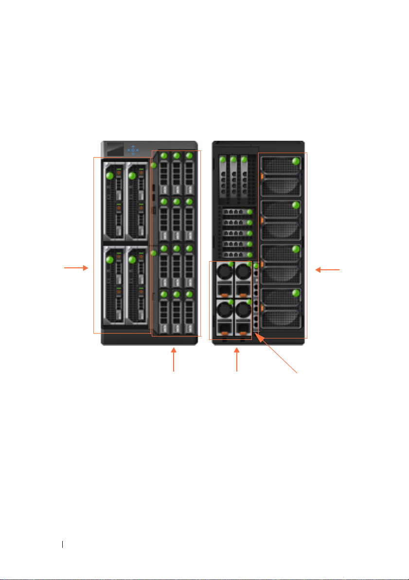
Blade
Servers
Shared
Storage
Power
Supplies
R1-2401
Fan
Tr a ys
Guide\Plasma_UGHW&InitialConfiguration.fm
Switch Ports
Figure 3-1 shows the R1-2401device within the chassis. Only the switch
hardware is described in this guide.
Figure 3-1. R1-2401
Types of Ports
The following ports are found on the switch:
•
24 x 1 Gigabit/s Ethernet Ports.
–
8 external ports
—Connected to network (visible when the switch is in
These consist of:
the chassis)
–
16 internal ports
—Connected to blade servers (not visible when the
switch is in the chassis)
DELL CONFIDENTIAL – PRELIMINARY 4/18/13 - FOR PROOF ONLY
30 Hardware and Initial Configuration
Page 31

FILE LOCATION: C:\Users\gina\Desktop\Checkout_new\Dell Plasma\User
Guide\Plasma_UGHW&InitialConfiguration.fm
• Single Internal Out-of-Band port
The switch supports an Out-of-Band (OOB) port that is connected to the
management network of the chassis.
Port Naming Convention
There are 5 groups of ports, numbered 0-4. Group 0 represents the external
ports and groups 1-4 represents the internal ports that are connected to blade
servers 1-4.
External/Internal Ports
The following naming convention is used for internal and external ports:
gigabitethernet group/port_number or gi group/port_number
The following table maps the hardware network port numbers to the software
interface port numbers and describe how they are referred to in the CLI/GUI:
Table 3-1. Port Mapping Table
Port Type and Number Software Port Naming Convention in CLI/WEB
External ports 1-8 gi0/1.... gi0/8
Internal ports 1-4 gi1/1.... gi1/4
Internal ports 5-8 gi2/1.... gi2/4
Internal ports 9-12 gi3/1.... gi3/4
Internal ports 13-16 gi4/1.... gi4/4
Out-of-Band port oob
Front Panel LEDs
The front panel contains LEDs and ports, as follows:
•
2 System LEDs
•
8 ports
— Each having two associated LEDs.
Ta b l e 3 - 3 .
Table 3-2. System LED’s
State of Switch Status LED Power LED (Green) Description
Off Off Off Switch is powered-
DELL CONFIDENTIAL – PRELIMINARY 4/18/13 - FOR PROOF ONLY
— Status and Power.
Hardware and Initial Configuration 31
These are described in Table 3-2.
These are described in
off.
Page 32

FILE LOCATION: C:\Users\gina\Desktop\Checkout_new\Dell Plasma\User
Table 3-2. System LED’s
State of Switch Status LED Power LED (Green) Description
Healthy/Booted Blue On Switch is
Fault Amber
Booting Off On Boot in progress.
Identify Blue Blink
Table 3-3. Port LEDs
LED Color
Link Off
Activity Off — No Link
Guide\Plasma_UGHW&InitialConfiguration.fm
•On — Self-diagnosed fault
Blink 1 HZ
1 HZ
—
No Link
Solid green
Solid amber
Blinking green
—
• Off
On CMC is identifying
Configuration error or
other CMC-detected fault
—
Link at 1G speed
—
Link at 10/100M speed
—
Traffic is being received/forward
functionally
normally.
Switch has issued a
fault.
the switch
Initial Configuration of the Switch
NOTE: Before proceeding further, read the latest documentation and release notes
for this product, which can be downloaded from the Dell Support website at
dell.com/support.
DELL CONFIDENTIAL – PRELIMINARY 4/18/13 - FOR PROOF ONLY
32 Hardware and Initial Configuration
Page 33

FILE LOCATION: C:\Users\gina\Desktop\Checkout_new\Dell Plasma\User
Guide\Plasma_UGHW&InitialConfiguration.fm
Table 3-4 describes the major switch defaults:
Table 3-4. Major System Defaults
Feature Defaults
SNMP Enabled.
SNMP version: V3
SNMP Local Engine ID: 0000000001
SNMP Notifications: Enabled
Login and Authentication Telnet authentication login is from the local
user data base
HTTP authentication login is from the
local data base
HTTPS authentication login is from the
local data base
Authentication Servers No RADIUS server is defined
No TACACS server is defined
Logging No SYSLOG server is defined
System Time SNTP is supported
DHCP DHCP server is disabled
DHCP auto configuration is enabled
Ports 24 GE regular ports
Full duplex is enabled.
Negotiation is enabled
Flow control is Off
No LAGs are defined
Multicast Multicast filtering is disabled
IGMP Snooping Disabled
Spanning Tree Enabled
VLANs Default VLAN is enabled
Default VLAN ID is 1
IP Addressing IP address is 192.168.2.1
DELL CONFIDENTIAL – PRELIMINARY 4/18/13 - FOR PROOF ONLY
Hardware and Initial Configuration 33
Page 34

FILE LOCATION: C:\Users\gina\Desktop\Checkout_new\Dell Plasma\User
NOTE: CLI and/or GUI need only be used if the default configuration is not
sufficient.
Guide\Plasma_UGHW&InitialConfiguration.fm
The switch can be configured in the following modes from the GUI:
•
Basic
— Elementary network configuration for the switch.
•
Advanced
— Full network configuration mode that enables configuration
of all switch capabilities. This mode is intended for advanced network
administrators.
To logon to the switch after it is inserted into the chassis, perform the
following:
1
Turn on the chassis. To display the IP address configured for the out-ofband interface, go to the CMC GUI, options:
I/O Module Overview >
Setup
2
Log on to the switch in one of the following ways:
– Establish a Telnet session to the out-of-band IP address obtained in
the last step, and log on with the default user/password:
root/calvin
Continue managing the switch through the CLI (see "Using the CLI"
on page 35).
– Open a GUI session from the CMC GUI, options:
Overview > Properties > Launch IOM GUI
I/O Module
. In the Login menu,
select either Basic or Advanced mode and use the default
user/password:
root/calvin
. Continue managing the switch through
the Network Administrator.
– Connect to the IOM serial interface through the CMC. For that, use
the CMC command:
consult the
CMC Command Line Reference
connect switch
. For more informations on this,
from
dell.com/support/manuals.
.
DELL CONFIDENTIAL – PRELIMINARY 4/18/13 - FOR PROOF ONLY
34 Hardware and Initial Configuration
Page 35

Using the CLI
This section describes how to perform various configuration operations
through the Command Line Interface CLI.
It includes the following topics:
•Using the CLI
• Accessing the Device Through the CLI
• Retrieving an IP Address
• Security Management and Password Configuration
• Configuring Login Banners
• Startup Menu Procedures
• Software Download
Using the CLI
This section provides some general information for using the CLI.
For a complete description of CLI commands, refer to the
VRTX 1Gb Switch Module, R1-2401 CLI Reference Guide
Dell PowerEdge
.
4
Command Mode Overview
The CLI is divided into command modes, each with a specific command set.
Entering a question mark at the terminal prompt displays a list of commands
available for that particular command mode.
In each mode, a specific command is used to navigate from one mode to
another.
These modes are described below.
User EXEC Mode
During CLI session initialization, the CLI is in User EXEC mode. Only a
limited subset of commands is available in User EXEC mode. This level is
reserved for tasks that do not change the terminal configuration and is used
to access configuration sub-systems.
DELL CONFIDENTIAL – PRELIMINARY 4/18/13 - FOR PROOF ONLY
Template Last Updated - 2/7/2007 Using the CLI 35
Page 36

FILE LOCATION: C:\Users\gina\Desktop\Checkout_new\Dell Plasma\User
Guide\Plasma_UGUsing_CLI.fm
After logging into the device, User EXEC command mode is enabled. The
user-level prompt consists of the host name followed by the angle bracket
(>). For example: console>
NOTE: The default host name is console unless it has been modified during
initial configuration.
The User EXEC commands enable connecting to remote devices, changing
terminal settings on a temporary basis, performing basic tests, and listing
system information.
To list the User EXEC commands, enter a question mark at the command
prompt.
To enter the next level, Privileged EXEC mode, a password is required (if
configured).
Privileged EXEC Mode
Privileged EXEC mode provides access to the device global configuration.
Privileged access can be protected, to prevent unauthorized access and to
secure operating parameters. Passwords are displayed on the screen, and are
case-sensitive.
NOTE: The enable command is only necessary if you login with privilege level less
than 15.
To access and list the Privileged EXEC mode commands:
1
At the prompt type
2
When a password prompt displays, enter the password and press
<Enter>
.
enable and press
<Enter>
.
The Privileged EXEC mode prompt displays as the device host name
followed by #. For example:
console#
To list the Privileged EXEC commands, type a question mark at the
command prompt.
To return from Privileged EXEC mode to User EXEC mode, type
and press
DELL CONFIDENTIAL – PRELIMINARY 4/18/13 - FOR PROOF ONLY
<Enter>
.
36 Using the CLI
disable
Page 37

FILE LOCATION: C:\Users\gina\Desktop\Checkout_new\Dell Plasma\User
Guide\Plasma_UGUsing_CLI.fm
The following example illustrates accessing privileged EXEC mode and then
returning to the User EXEC mode:
console>enable
Enter Password: ******
console#
console# disable
console>
Use the exit command to return to a previous mode.
To configure the device, enter the next level, Global Configuration mode.
Global Configuration Mode
The Global Configuration mode manages device configuration on a global
level. Global Configuration commands apply to system features, rather than a
specific protocol or interface.
To access Global Configuration mode, at the Privileged EXEC Mode prompt,
type configure and press <Enter>. The Global Configuration mode displays
as the device host name followed by (config) and the pound sign #:
console# configure
console(config)#
To list the Global Configuration commands, enter a question mark at the
command prompt.
The following example illustrates how to access Global Configuration mode
and return back to the Privileged EXEC mode:
console#
console# configure
console(config)# exit
console#
Interface Configuration Mode
The Interface Configuration mode configures the device at the physical
interface level (port, VLAN, or LAG). Interface commands that require
subcommands have another level, called the Subinterface Configuration
mode. A password is not required to access this level.
DELL CONFIDENTIAL – PRELIMINARY 4/18/13 - FOR PROOF ONLY
Using the CLI 37
Page 38

FILE LOCATION: C:\Users\gina\Desktop\Checkout_new\Dell Plasma\User
Guide\Plasma_UGUsing_CLI.fm
The following example, places the CLI in Interface Configuration mode on
port gi0/1. The sntp command is then applied to that port.
console# configure
console(config)# interface gi0/1
console(config-if)# sntp client enable
To run a command in a mode, which does not contain it, use do before the
command, as in the following example:
console# configure
console(config)# interface gi0/1
console(config-if)# sntp client enable
console(config-if)# do show sntp configuration
CLI Command Conventions
There are certain command entry conventions that apply to all commands.
The following table describes these conventions.
Table 4-1. Common GUI Elements
Button Description
[ ] In a command line, square brackets indicate an optional
entry.
{ } In a command line, curly brackets indicate a selection of
compulsory parameters separated by the | character. One
option must be selected. For example: flowcontrol
{auto|on|off} means that for the flowcontrol command
either auto, on, or off must be selected.
Italic Font
Bold Italic Font
<button-name> Any individual key on the keyboard. For example click
Ctrl+F4 Any combination of keys clicked simultaneously, for example:
Screen Display Indicates system messages and prompts appearing on the
Indicates a parameter value.
Indicates a parameter key word.
<Enter>.
Ctrl and F4.
console.
DELL CONFIDENTIAL – PRELIMINARY 4/18/13 - FOR PROOF ONLY
38 Using the CLI
Page 39

FILE LOCATION: C:\Users\gina\Desktop\Checkout_new\Dell Plasma\User
Button Description
all
Guide\Plasma_UGUsing_CLI.fm
When a parameter is required to define a range of ports or
parameters and all is an option, the default for the command
is all when no parameters are defined. For example, the
command interface range port-channel has the option of
either entering a range of channels, or selecting all. When the
command is entered without a parameter, it automatically
defaults to all.
Accessing the Device Through the CLI
You can manage the device using CLI commands, through the CMC to the
terminal console, or via a Telnet connection.
Through CMC
Insert the device into the chassis and enter the CLI commands upon
receiving a prompt.
Telnet Connection
Telnet is a terminal emulation TCP/IP protocol. RS-232 terminals can be
virtually connected to the local device through a TCP/IP protocol network.
Telnet is an alternative to a local login terminal, where a remote login is
required.
The device supports up to four simultaneous Telnet sessions. All CLI
commands can be used over a Telnet session.
If access is via a Telnet connection, ensure that the device has an IP address
and that software has been downloaded to the device.
To start a Telnet session:
1
Select
The
Start > Run
Run
window opens.
.
2
Ty p e
cmd.
The
cmd
window opens.
3
In the
cmd
window, type
DELL CONFIDENTIAL – PRELIMINARY 4/18/13 - FOR PROOF ONLY
Telnet <IP address> <Enter>
Using the CLI 39
.
Page 40

FILE LOCATION: C:\Users\gina\Desktop\Checkout_new\Dell Plasma\User
Guide\Plasma_UGUsing_CLI.fm
The Telnet session begins.
Retrieving an IP Address
By default, the switch receives its IP address dynamically via a DHCP server.
You can change the OOB port’s IP, but you cannot delete it. and you can add
another IP address on the In-Band interface (port, port-channel or VLAN).
The In-Band IP address can also be received from the DHCP server.
Receiving an In-Band IP Address from a DHCP Server
When using the DHCP protocol to retrieve an IP address, the device acts as a
DHCP client. When the device is reset, the DHCP command is saved in the
configuration file, but the IP address is not.
To retrieve an IP address from a DHCP server, perform the following steps:
1
Select and connect any port to a DHCP server or to a subnet that has a
DHCP server on it.
2
Type the following commands to use the selected port for receiving the IP
address:
a
Assigning dynamic IP Addresses on a port:
console# configure
console(config)# interface gi0/1
console(config-if)# ip address dhcp
b
Assigning a dynamic IP Addresses on a VLAN:
console# configure
console(config)# interface vlan 1
console(config-if)# ip address dhcp
The interface receives the IP address automatically.
DELL CONFIDENTIAL – PRELIMINARY 4/18/13 - FOR PROOF ONLY
40 Using the CLI
Page 41

FILE LOCATION: C:\Users\gina\Desktop\Checkout_new\Dell Plasma\User
3
Type the following to verify the IP address:
console# show ip interface
Gateway IP Address Activity status Type
----------------------- ----------------------- --------
10.5.225.33 Active dhcp
IP Address I/F Type Status
------------------ --------- ----------- -----------
10.5.225.45/27 vlan 1 DHCP Valid
Guide\Plasma_UGUsing_CLI.fm
When configuring/receiving IP addresses through DHCP and BOOTP (an
older version of DHCP), the configuration received from these servers
includes the IP address and may include the subnet mask and default
gateway.
NOTE: It is not necessary to delete the device configuration to retrieve an IP
address from the DHCP server.
NOTE: When copying configuration files, avoid using a configuration file that
contains an instruction to enable DHCP on an interface that connects to the same
DHCP server, or to one with an identical configuration. In this instance, the device
retrieves the new configuration file and boots from it. The device then enables
DHCP, as instructed in the new configuration file, and the DHCP instructs it to reload
the same file.
NOTE: If you configure a DHCP IP address, this address is dynamically retrieved,
and the ip address dhcp command is saved in the configuration file. In the event of
master failure, the backup will again attempt to retrieve a DHCP address. This could
result in one of the following:
• The same IP address may be assigned.
• A different IP address may be assigned, which could result in loss of
connectivity to the management station.
• The DHCP server may be down, which would result in IP address retrieval
failure, and possible loss of connectivity to the management station.
DELL CONFIDENTIAL – PRELIMINARY 4/18/13 - FOR PROOF ONLY
Using the CLI 41
Page 42

FILE LOCATION: C:\Users\gina\Desktop\Checkout_new\Dell Plasma\User
Guide\Plasma_UGUsing_CLI.fm
Security Management and Password Configuration
System security is handled through the Authentication, Authorization, and
Accounting (AAA) mechanism that manages user access rights, privileges,
and management methods. AAA uses both local and remote user databases.
Data encryption is handled through the SSH mechanism.
Passwords can be configured for the following services:
•Terminal
•Telnet
• SSH
•HTTP
•HTTPS
NOTE: When creating a user name, the default priority is 14, which provides
access but not configuration rights. A priority of 15 must be set to enable access
and configuration rights to the device. Although user names can be assigned
privilege level 15 without a password, it is recommended to always assign a
password. If there is no specified password, privileged users can access the Web
interface with any password.
NOTE: Passwords can be secured by using password management commands to
force aging out of passwords, or expiration of passwords. For more information, see
"Management Security" on page 131.
Initial Configuration and Password Recovery
The system is delivered with a default username/password (root/calvin). If a
user-defined password is lost, a password recovery procedure can be invoked
from the Startup menu. This procedure is applicable for the local terminal
only and enables a single access to the device from the local terminal with no
password entered.
The full mode of password recovery mechanism can be enabled/disabled
through the CLI (service password-recovery command).
This affects password recovery in the following way:
•
Enabled:
access to the device without a password is enabled and all configuration
and user files are retained.
DELL CONFIDENTIAL – PRELIMINARY 4/18/13 - FOR PROOF ONLY
42 Using the CLI
When the password-recovery mechanism is invoked, one-time
Page 43

•
FILE LOCATION: C:\Users\gina\Desktop\Checkout_new\Dell Plasma\User
Disabled:
When the password-recovery mechanism is invoked, one-time
Guide\Plasma_UGUsing_CLI.fm
access to the device without a password is stilled enabled, however all
configuration files (startup and backups) are removed and the following
log message is generated to the terminal after boot process completed: “All
configuration and user files were removed”
Configuring an Initial Terminal Password
To configure an initial terminal password, enter the following commands:
console(config)# aaa authentication login default line
console(config)# aaa authentication enable default line
console(config)# line console
console(config-line)# login authentication default
console(config-line)# enable authentication default
console(config-line)# password george
Configuring an Initial Telnet Password
To configure an initial Telnet password, enter the following commands:
console(config)# aaa authentication login default line
console(config)# aaa authentication enable default line
console(config)# line telnet
console(config-line)# login authentication default
console(config-line)# enable authentication default
console(config-line)# password bob
DELL CONFIDENTIAL – PRELIMINARY 4/18/13 - FOR PROOF ONLY
Using the CLI 43
Page 44

FILE LOCATION: C:\Users\gina\Desktop\Checkout_new\Dell Plasma\User
Guide\Plasma_UGUsing_CLI.fm
Configuring an Initial SSH Password
To configure an initial SSH password, enter the following commands:
console(config)# aaa authentication login default line
console(config)# aaa authentication enable default line
console(config)# line ssh
console(config-line)# login authentication default
console(config-line)# enable authentication default
console(config-line)# password jones
Configuring an Initial HTTP Password
To configure an initial HTTP password, enter the following commands:
console(config)# ip http authentication aaa login-authentication local
console(config)# username admin password user1 privilege 15
Configuring an Initial HTTPS Password
To configure an initial HTTPS password, enter the following commands:
console(config)# ip http authentication aaa login-authentication local
console(config)# username admin password user1 privilege 15
Enter the following commands once when configuring use of a terminal, a
Telnet, or an SSH session, for an HTTPS session.
NOTE: In the Web browser, enable SSL 2.0 or greater for the page content to be
displayed.
console(config)# crypto certificate 1 generate key-generate
console(config)# ip http secure-server
NOTE: HTTP and HTTPS services require privilege level 15 access and connect
directly to the configuration level access.
Configuring Login Banners
Banners can be defined for each line, such as console and telnet) or for all
lines. They are disabled by default.
DELL CONFIDENTIAL – PRELIMINARY 4/18/13 - FOR PROOF ONLY
44 Using the CLI
Page 45

FILE LOCATION: C:\Users\gina\Desktop\Checkout_new\Dell Plasma\User
Guide\Plasma_UGUsing_CLI.fm
The following types of banners can be defined:
•
Message-of-the-Day Banner (motd)
— Displayed when the user connects
to the device, before login. The following defines a message-of-the-day for
the console:
console# configure
console(config)# line console
console(config-line)# motd-banner
console(config-line)# exit
console (config)# banner motd *
Welcome*
console# do show banner motd
Banner: MOTD
Welcome
console(config)#
Login Banner — Displayed after the Message-of-the-Day Banner, and
•
before the user has logged in. The following defines a login banner for the
console:
console# configure
console(config)# line console
console(config-line)# login-banner
console(config-line)# exit
console (config)# banner login *
Please log in*
console# do show banner login
Banner: Login
Please log in
console(config)#
Exec Banner — Displayed after successful login (in all privileged levels
•
and in all authentication methods). The following defines an exec banner
DELL CONFIDENTIAL – PRELIMINARY 4/18/13 - FOR PROOF ONLY
Using the CLI 45
Page 46

FILE LOCATION: C:\Users\gina\Desktop\Checkout_new\Dell Plasma\User
Guide\Plasma_UGUsing_CLI.fm
for the console:
console# configure
console(config)# line console
console(config-line)# exec-banner
console(config-line)# exit
console (config)# banner exec *
Successfully logged in*
Would you like to enable this banner to all lines? (Y/N)[Y] Y
console# do show banner exec
Banner: Exec
Successfully logged in
console(config)#
Startup Menu Procedures
The Startup menu enables performing various tasks, such as software
download, flash handling and password recovery.
You can enter the Startup menu when booting the device. User input must be
entered immediately after the POST test.
To enter the Startup menu:
• Turn the power on. After the auto-boot messages appear, the following
menu is displayed:
[1]Download Software
[2]Erase Flash File
[3]Password Recovery Procedure
[4]Set Terminal Baud-Rate
[5]Back
The sections below describe the available Startup menu options.
NOTE: When selecting an option from the Startup menu, take the time-out interval
into account. If no selection is made within 10 seconds (default), the device times
out. This default value can be changed through the CLI.
DELL CONFIDENTIAL – PRELIMINARY 4/18/13 - FOR PROOF ONLY
46 Using the CLI
Page 47

FILE LOCATION: C:\Users\gina\Desktop\Checkout_new\Dell Plasma\User
Guide\Plasma_UGUsing_CLI.fm
Download Software - Option[1]
The software download procedure is used to replace corrupted files or
upgrade system software, when the device does not have IP connectivity or
when both software images of the device are corrupted and therefore you
cannot use the web-based management system.
NOTE: it is highly recommended that, before loading via xmodem, the baud rate of
the device and terminal be set to 115200.
To download software through the Startup menu:
1
From the Startup menu,
Downloading code using XMODEM
!!!!!!!!!!!!!!!!!!!!!!!!!!!!!!!!!!!
2
When using the HyperTerminal, click
Menu Bar and select
3
In the
Filename
4
Ensure that the Xmodem protocol is selected in the
5
Press
Send
NOTE: After software download, the device reboots automatically.
field, enter the file path for the file to be downloaded.
. The software is downloaded.
press [1]
Send File
. The following prompt is displayed:
Tr an sf e r
on the HyperTerminal
.
Protocol
field.
Erase FLASH File - Option[2]
In some cases, the device Startup Configuration file must be erased. If the
configuration is erased, all parameters configured via CLI, web-management
or SNMP must be reconfigured.
To erase the device configuration in the Startup Configuration file:
1
From the Startup menu,
displayed:
Warning! About to erase a Flash file.
Are you sure (Y/N)?
2
Press Y. The following message is displayed.
Write Flash file name (Up to 8 characters, Enter
for none.):
DELL CONFIDENTIAL – PRELIMINARY 4/18/13 - FOR PROOF ONLY
select [2]
. The following message is
Using the CLI 47
Page 48

FILE LOCATION: C:\Users\gina\Desktop\Checkout_new\Dell Plasma\User
3
Enter
config
("config" is the standard name for the Startup configuration
Guide\Plasma_UGUsing_CLI.fm
file although you can use any name).
The following is displayed:
File config (if present) will be erased after system initialization
======== Press Enter To Continue ========
The configuration is erased when the system is reset.
Password Recovery - Option[3]
If a password is lost, the Password Recovery procedure can be called from the
Startup menu. The procedure enables entry to the device a single time
without entering a password.
To recover a lost password when entering the local terminal only:
1
From the
2
Continue the regular startup by logging in without a password.
3
Enter a new password or press 'ESC' to exit.
NOTE: To ensure device security, reconfigure passwords for applicable
management methods.
Startup
menu, select
[3]
.
Set Terminal Baud-Rate - Option[4]
To set the terminal baud-rate:
1
Ty p e
[4]
and press
<Enter>
.
2 Enter the new baud rate. The following is displayed:
Set new device baud-rate: 38,400
Note that after this step, your terminal will no longer respond. Adjust your
terminal speed to the configured one.
Software Download
This section contains instructions for downloading device software (system
and boot images) through a TFTP server. The TFTP server must be
configured before downloading the software.
DELL CONFIDENTIAL – PRELIMINARY 4/18/13 - FOR PROOF ONLY
48 Using the CLI
Page 49

FILE LOCATION: C:\Users\gina\Desktop\Checkout_new\Dell Plasma\User
Guide\Plasma_UGUsing_CLI.fm
System Image Download
When the device boots, it decompresses the system image from the flash
memory area and runs it. When a new image is downloaded, it is saved in the
other area allocated for the other system image copy.
On the next boot, the device decompresses and runs the image from the
currently active system image.
A system image can be downloaded through a TFTP server.
To download the system image from a TFTP server, ensure that an IP address
is configured on one of the device ports and pings can be sent to the TFTP
server. In addition, ensure that the file to be downloaded is saved on the
TFTP server.
To download a system image through the TFTP server:
1
Enter the
currently running on the device. The following is an example of the
information that appears:
console# show version
SW version 1.0.0.17 ( date 05-Sep-2012 time 12:05:41 )
Boot version 1.0.0.2 ( date 22-Aug-2012 time 15:56:52 )
HW version
console#
show version
command, to verify which software version is
2
Enter the
show bootvar
command, to verify which system image is
currently active. The following is an example of the information that is
displayed:
console# show bootvar
Image Filename Version Date Status
----- --------- --------- --------------------- -----1 image-1 1.0.0.13 04-Aug-2010 08:27:30 Active*
2 image-2 1.0.0.12 29-Jul-2010 17:02:26 Not active
console#
3
Enter the one of the following commands to copy a new system image to
the current unit:
To copy a new system image to the device:
copy tftp://{tftp address}/{file name} image
DELL CONFIDENTIAL – PRELIMINARY 4/18/13 - FOR PROOF ONLY
Using the CLI 49
Page 50

FILE LOCATION: C:\Users\gina\Desktop\Checkout_new\Dell Plasma\User
4
When the new image is downloaded, it is saved in the area allocated for
Guide\Plasma_UGUsing_CLI.fm
the other copy of the system image (image-2, as shown in the example).
The following is an example of the information that appears:
console# copy tftp://176.215.31.3/r2401-100048.ros image
Accessing file ‘r2401-100048’ on 176.215.31.3Ö
Loading r2401-100048 from 176.215.31.3:
!!!!!!!!!!!!!!!!!!!!!!!!!!!!!!!!!!!!!!!!!!!!!!!!
Copy took 00:01:11 [hh:mm:ss]
Exclamation symbols indicate that a copying process is in progress. Each
symbol (!) corresponds to 512 bytes transferred successfully. A period
indicates that the copying process is timed out. Many periods in a row
indicate that the copying process failed.
5
Select the image for the next boot by entering the
After this command, enter the
copy indicated as a parameter in the
show bootvar
boot system
boot system
command.
command to verify that the
command is selected for
the next boot.
The following is an example of the information that appears:
console# boot system image-2
console# show bootvar
Images currently available on the Flash
Image-1 active
Image-2 not active (selected for next boot)
If the image for the next boot is not selected by entering the boot system
command, the system boots from the currently active image.
6
Enter the reload command. The following message is displayed:
console# reload
This command will reset the whole system and disconnect your current
session. Do you want to continue (y/n) [n]?
7
Enter Y. The device reboots.
Boot Image Download
Loading a new boot image from the TFTP server, updates the boot image.
The boot image is loaded when the device is powered on. A user has no
control over the boot image copies.
DELL CONFIDENTIAL – PRELIMINARY 4/18/13 - FOR PROOF ONLY
50 Using the CLI
Page 51

FILE LOCATION: C:\Users\gina\Desktop\Checkout_new\Dell Plasma\User
Guide\Plasma_UGUsing_CLI.fm
To download a boot image through the TFTP server:
1
Enter the
show version
command to verify which software version is
currently running on the device. The following is an example of the
information that appears:
console# show version
SW version 1.0.0.17 ( date 05-Sep-2012 time 12:05:41 )
Boot version 1.0.0.2 ( date 22-Aug-2012 time 15:56:52 )
HW version
2
Enter the
copy {tftp://}{tftp address}/{file name} boot
command to copy the boot image to the device. The following is an
example of the information that appears:
console# copy tftp://50.1.1.7/r2401-boot-1009.rfb boot
01-Oct-2006 11:57:35 %COPY-I-FILECPY: Files Copy - source URL
tftp://50.1.1.7/r2401-1009.rfb destination URL flash://boot
!!!!!!!!!!!!!!!!!!!!!!!!!!!!!!!!!!!!!!
01-Sep-2010 11:57:38 %INIT-I-Startup: Cold Startup
!!!!!!!!!!!!!!!!!!!!!!!!!!!!!!!!!!!!!!!!!!!!!!!!!!!!
01-Sep-2010 11:59:05 %COPY-N-: The copy operation was completed
successfully!
Copy: 522288 bytes copied in 00:01:30 [hh:mm:ss]
3
Enter the reload command. The following message is displayed:
console# reload
This command will reset the whole system and disconnect your current
session. Do you want to continue (Y/N) [N]?
4
Enter Y. The device reboots.
DELL CONFIDENTIAL – PRELIMINARY 4/18/13 - FOR PROOF ONLY
Using the CLI 51
Page 52

FILE LOCATION: C:\Users\gina\Desktop\Checkout_new\Dell Plasma\User
Guide\Plasma_UGUsing_CLI.fm
DELL CONFIDENTIAL – PRELIMINARY 4/18/13 - FOR PROOF ONLY
52 Using the CLI
Page 53

Network Administrator.
This section describes how to manage the device using the web-based
Network Administrator.
It contains the following topics:
• Starting the Application
• Understanding the Interface
• Using the Network Administrator Buttons
• Field Definitions
• Common GUI Features
• CLI Commands
Starting the Application
NOTE: Before starting the application the IP address must be defined. For more
information, see "Accessing the Device Through the CLI" on page 61.
1
Open the CMC GUI.
2
Press the
3
Enter a user name and password.
Launch IOM GUI
button.
5
NOTE: Passwords are both case sensitive and alpha-numeric.
4
Click OK.
The
Network Administrator
home page displays.
Understanding the Interface
The home page contains the following views:
•
Tree view
provides an expandable view of the features and their components. The
branches in the tree view can be expanded to view all the components
DELL CONFIDENTIAL – PRELIMINARY 4/18/13 - FOR PROOF ONLY
Template Last Updated - 2010 Network Administrator. 53
— Located on the left side of the home page, the tree view
Page 54

FILE LOCATION: C:\Users\gina\Desktop\Checkout_new\Dell Plasma\User
Guide\Plasma_UGUsing_GUI.fm
under a specific feature, or closed to hide the feature's components. By
dragging the vertical bar to the right, the tree area can be expanded to
display the full name of a component.
•
Device View
— Located in on the top center of the home page, the device
view provides information about device ports, current configuration and
status, table information, and feature components. For further
information, see "Device Representation" on page 54
Components List
•
— Located in the bottom center of the home page,
contains a list of the feature components. When a feature is expanded, the
GUI page for that feature is displayed.
•
Information Buttons
— Located at the top of the home page, provide
access to information about the device and access to Dell Support. For
more information, see "Information Buttons" on page 54.
Device Representation
The graphic display on the home page displays port and system LEDS that
specify whether a specific port is currently active.
See "Front Panel LEDs" on page 31.
To configure a port double-click on its icon.
Using the Network Administrator Buttons
This section describes the buttons found on the Network Administrator
interface.
Information Buttons
Table 5-1 describes the information buttons that provide access to online
support and online help, as well as information about the Network
Administrator interfaces. These are displayed at the top of each page.
Table 5-1. Information Buttons
Button Description
Mode You are either in Basic or Advanced mode according to your
user privileges. Basic mode has a subset of the features
available. Advanced mode has all features available.
DELL CONFIDENTIAL – PRELIMINARY 4/18/13 - FOR PROOF ONLY
54 Network Administrator.
Page 55

FILE LOCATION: C:\Users\gina\Desktop\Checkout_new\Dell Plasma\User
Table 5-1. Information Buttons
Button Description
Support Opens the Dell Support page at support.dell.com
About Contains the version and build number and Dell copyright
Logout Opens the Log Out window.
Guide\Plasma_UGUsing_GUI.fm
information.
Device Management Icons
Table 5-2 describes the device management buttons.
Table 5-2. Device Management Icons
Button Icon Description
Apply&Save Saves changes to the Running and Startup Configuration
files.
Help Open online help. The online help pages are
context-sensitive. For example, if the IP Addressing page is
open, the help topic for that page is displayed when Help is
clicked.
Print Prints the Network Management System page and/or table
information.
Refresh Refreshes device information from the Running
Configuration file.
Field Definitions
Fields that are user-defined can contain between 1–159 characters, unless
otherwise noted on the Network Administrator web page. All letters or
characters can be used, except the following: "\ / : * ? < >"
DELL CONFIDENTIAL – PRELIMINARY 4/18/13 - FOR PROOF ONLY
Network Administrator. 55
Page 56

FILE LOCATION: C:\Users\gina\Desktop\Checkout_new\Dell Plasma\User
Guide\Plasma_UGUsing_GUI.fm
Common GUI Features
Table 5-3 describes the common functions that can be performed on many
GUI pages.
Table 5-3. Common GUI Elements
Button Description
Apply Save changes entered in GUI page to the Running
Configuration file.
Back Go to previous page.
Cancel Cancel changes entered in GUI page.
Clear All Counters Delete counters.
Clear Counters Delete selected counters.
Clear Log Delete entries from log.
Clear Statistics Delete statistics.
Copy parameters
from
Copy parameters
from port
Details Shows further details relevant to the current page.
Next Go to next page.
Query Run a query after query criteria have been entered.
Remove Remove checked elements in the page. If Select All is
Reset All Counters Delete all counters.
Restore Defaults Restores parameters entered in page to default values.
Te ln e t Opens a Telnet window. This only works in the Explorer 6 and
Copy the parameters from a selected row to the selected
target rows.
Copy the parameters from a selected port to the selected
target ports.
selected, all elements are removed.
Firefox browsers.
DELL CONFIDENTIAL – PRELIMINARY 4/18/13 - FOR PROOF ONLY
56 Network Administrator.
Page 57

FILE LOCATION: C:\Users\gina\Desktop\Checkout_new\Dell Plasma\User
Guide\Plasma_UGUsing_GUI.fm
GUI Terms
Each GUI page in the tree view is described in the following sections. A brief
introduction is provided along with steps specifying how to enter information
in the page. The following terms are used:
•
Enter
— Indicates that information may be entered in the field. It does
not imply that the field is mandatory.
•
Select
—Indicates that information may be selected from a drop-down list
or from radio buttons.
•
Displays
—Indicates that the field is display only.
DELL CONFIDENTIAL – PRELIMINARY 4/18/13 - FOR PROOF ONLY
Network Administrator. 57
Page 58

FILE LOCATION: C:\Users\gina\Desktop\Checkout_new\Dell Plasma\User
Guide\Plasma_UGUsing_GUI.fm
DELL CONFIDENTIAL – PRELIMINARY 4/18/13 - FOR PROOF ONLY
58 Network Administrator.
Page 59

6
Configuring System Information
This section describes how to set system parameters, such as security features,
switch software, system time, logging parameters and more.
It contains the following topics:
• General Switch Information
• Time Synchronization
•Logs
• IP Addressing
•Diagnostics
• Management Security
•SNMP
•File Management
General Switch Information
This section describes how to view and set general switch parameters.
It contains the following topics:
•Asset Information
• System Health
Asset Information
Use the Asset page to view and configure general device information,
including the system name, location, contact, system MAC Address, System
Object ID, date, time, and system up time.
To configure general device parameters:
1
Click
System > General > Asset
2
Enter/view the parameters:
–
System Name (0-159 Characters)
name.
DELL CONFIDENTIAL – PRELIMINARY 4/18/13 - FOR PROOF ONLY
Template Last Updated - 2010 59
in the tree view to display the
— Enter the user-defined device
Asset
page.
Page 60

FILE LOCATION: C:\Users\gina\Desktop\Checkout_new\Dell Plasma\User
–
System Contact (0-159 Characters)
Guide\Plasma_UGSystemConfig.fm
— Enter the name of the contact
person.
–
System Location (0-159 Characters)
— Enter the location where the
system is currently running.
–
MAC Address
–
OOB MAC Address
— Displays the device MAC address.
— Displays the MAC address of the Out-of-Band
port.
–
Sys Object ID
— Displays the vendor's authoritative identification of
the network management subsystem contained in the entity.
–
Date
— Enter the current date (mandatory). This date can also be
entered in the
Manual Time Settings
page. If SNTP has been defined,
but the SNTP server is not available, the switch uses the date and time
Time
in this field and the
–
Time
— Enter the current time (mandatory). This time can also be
entered in the
Manual Time Settings
field.
page. If SNTP has been defined,
but the SNTP server is not available, the switch uses the date and time
Date
in this field and the
–
System Up Time
— Displays the amount of time since the last device
field.
reset.
–
Service Tag
— Displays the service reference number used when
servicing the device.
–
Asset Tag
— Enter the
Asset Tag (0-16 Characters)
for the device.
This is the user-defined reference for the device.
–
Serial No.
— Displays the device serial number.
60
DELL CONFIDENTIAL – PRELIMINARY 4/18/13 - FOR PROOF ONLY
Page 61

FILE LOCATION: C:\Users\gina\Desktop\Checkout_new\Dell Plasma\User
Entering Asset Information Using the CLI Commands
Guide\Plasma_UGSystemConfig.fm
The following table summarizes the CLI commands for entering fields
displayed on the Asset
Table 6-1. Asset CLI Command
CLI Command Description
snmp-server contact text
no snmp-server contact
snmp-server location text
no snmp-server location
hostname name
no hostname
clock set hh:mm:ss {[day
page.
Configures the system contact
(sysContact) name.
Use the no form of the command to
remove the system contact
information.
Configures the system location
string.
Use the no form of this command to
remove the location string.
Specifies the device host name.
Use the no form of the command to
remove the existing host name.
Sets the system clock to this time.
month] | [month day]} year
asset-tag tag
no asset-tag
Assigns the asset tag to the device.
Use the no form of this command to
remove the asset tag from the device.
The following is an example of the CLI commands
console (config)# asset-tag 2365491870
System Health
There are five temperature sensors for monitoring the temperature of the
switch and the ambient temperature.
To view the device’s temperature information:
1
Click
System > General > System Health
System Health page.
This page displays the temperature of each sensor, as follows:
DELL CONFIDENTIAL – PRELIMINARY 4/18/13 - FOR PROOF ONLY
in the tree view to display the
61
Page 62

FILE LOCATION: C:\Users\gina\Desktop\Checkout_new\Dell Plasma\User
–
Ambient Temperature Sensor
Guide\Plasma_UGSystemConfig.fm
— Temperature surrounding the
switch.
•
Current Temperature (Celsius)
— Current temperature around
the switch.
•
Target Temperature (Celsius)
— Maximum temperature allowed
around the switch.
–
Switch Temperature Sensor
•
Current Temperature (Celsius)
— Temperature inside the switch.
— Current temperature inside
the switch.
•
Target Temperature (Celsius)
— Maximum temperature allowed
inside the switch.
–
Component 1
•
Current Temperature (Celsius)
—Temperature inside this IOM component.
— Current temperature inside
the IOM component 88E1680.
•
Target Temperature (Celsius)
— Maximum temperature allowed
inside the IOM component 88E1680.
–
Component 2
•
Current Temperature (Celsius)
—Temperature inside this IOM component.
— Current temperature inside
the IOM component 88E1340 (U13).
•
Target Temperature (Celsius)
— Maximum temperature allowed
inside the IOM component 88E1340 (U13).
–
Component 3
•
Current Temperature (Celsius)
—Temperature inside this IOM component.
— Current temperature inside
the IOM component 88E1340 (U14).
•
Target Temperature (Celsius)
— Maximum temperature allowed
inside the IOM component 88E1340 (U14).
–
Table 6-2. Celsius to Fahrenheit Conversion Table
Celsius Fahrenheit
0 32
541
10 50
DELL CONFIDENTIAL – PRELIMINARY 4/18/13 - FOR PROOF ONLY
62
Page 63

FILE LOCATION: C:\Users\gina\Desktop\Checkout_new\Dell Plasma\User
Guide\Plasma_UGSystemConfig.fm
Celsius Fahrenheit
15 59
20 68
25 77
30 86
35 95
40 104
DELL CONFIDENTIAL – PRELIMINARY 4/18/13 - FOR PROOF ONLY
63
Page 64

FILE LOCATION: C:\Users\gina\Desktop\Checkout_new\Dell Plasma\User
Guide\Plasma_UGSystemConfig.fm
Viewing System Health Information Using the CLI Commands
The following table summarizes the CLI commands for viewing fields
displayed on the System Health
Table 6-3. System Health CLI Command
CLI Command Description
show system sensor
page.
Displays sensor temperature information.
The following is an example of the CLI commands:
console# show system sensor
Temperature Current Temperature Target Temperature
Sensor Type (C) (C)
------------------------ ------------------- ------------------Ambient temperature sensor 47 60
Switch temperature sensor 53 60
Component 1 51 60
Component 2 52 60
Component 3 51 60
Time Synchronization
The system clock runs from the moment the system starts up, and keeps track
of the date and time.
The date and time may be either set manually, or it may be received from an
SNTP server.
This section describes how to set system time, and contains the following
sections:
• Global Settings (Clock Source)
• Manual Time Settings
– Setting System Time and Daylight Savings Time
– CLI Commands for Setting Manual Time
• System Time from an SNTP Server
– SNTP Global Settings
– SNTP Authentication
DELL CONFIDENTIAL – PRELIMINARY 4/18/13 - FOR PROOF ONLY
64
Page 65

FILE LOCATION: C:\Users\gina\Desktop\Checkout_new\Dell Plasma\User
Guide\Plasma_UGSystemConfig.fm
–SNTP Servers
–SNTP Interfaces
– CLI Script for Receiving Time from an SNTP Server
Global Settings (Clock Source)
System time can be set manually, or it may be received from an external
SNTP server. You if wish to set the system time manually, you do not to use
the Global Settings page, because the default is manual (local) system time.
To set the clock source:
1
Click
to display the
2
Select the
–
Local —
as defined in "Manual Time Settings" on page 66.
–
SNTP —
as defined in "System Time from an SNTP Server" on page 73.
System > Time Synchronization > Global Settings
Global Settings
Clock Source
page.
. The possible options are:
System time is taken from the device’s internal clock. Set this
System time is set via an SNTP server. Set SNTP parameters
in the tree view
DELL CONFIDENTIAL – PRELIMINARY 4/18/13 - FOR PROOF ONLY
65
Page 66

FILE LOCATION: C:\Users\gina\Desktop\Checkout_new\Dell Plasma\User
Guide\Plasma_UGSystemConfig.fm
Defining the Clock Source Using CLI Commands
The following table summarizes the CLI commands for setting the clock
source.
Table 6-4. Clock Source CLI Command
CLI Description
clock source sntp
no clock source
show clock [detail] Displays the time and date from the system
Configures an external time source for the
system clock.
Use the no form of this command to disable
the external time source.
clock and its source.
The following is an example of the CLI commands:
console# configure
console(config)# clock source sntp
console# show clock detail
3:29:03 UTC Sep 7 2010
Time source is sntp
Time zone:
Offset is UTC+0
Manual Time Settings
This section describes how to set the system time manually on the device.
It contains the following topics:
• Setting System Time and Daylight Savings Time
• CLI Commands for Setting Manual Time
DELL CONFIDENTIAL – PRELIMINARY 4/18/13 - FOR PROOF ONLY
66
Page 67

FILE LOCATION: C:\Users\gina\Desktop\Checkout_new\Dell Plasma\User
Setting System Time and Daylight Savings Time
Guide\Plasma_UGSystemConfig.fm
Use the Manual Time Settings page to set system date/time manually (as
opposed to receiving them from an external SNTP server). For more
information on SNTP, see "System Time from an SNTP Server" on page 73.
If system time is kept using an external SNTP clock, and the external SNTP
clock fails, the system time reverts to the time set here or in the Asset page.
In addition to setting the local clock, you can use this page to enable Daylight
Savings Time (DST) on the device.
The following is a list of DST start and end times in various countries:
•
•
•
Albania
Australia
Australia
— Last weekend of March until the last weekend of October.
— From the end of October until the end of March.
- T
asmania
— From beginning of October until the end of
March.
•
•
•
Armenia
Austria
Bahamas
— Last weekend of March until the last weekend of October.
— Last weekend of March until the last weekend of October.
— From April to October, in conjunction with U.S. summer
hours.
•
Belarus
— Last weekend of March until the last weekend of October.
•
•
Belgium
Brazil
— Last weekend of March until the last weekend of October.
— From the 3rd Sunday in October until the 3rd Saturday in
March. During the period of Daylight Saving Time, Brazilian clocks go
forward one hour in most of the Brazilian southeast.
•
Chile
— Easter Island 9th March 12th October. The first Sunday in March
or after 9th March.
•
China
— China does not operate Daylight Saving Time.
•
Canada
— From the first Sunday in April until the last Sunday of October.
Daylight Saving Time is usually regulated by provincial and territorial
governments. Exceptions may exist in certain municipalities.
•
Cuba
— From the last Sunday of March to the last Sunday of October.
•
Cyprus
— Last weekend of March until the last weekend of October.
•
•
Denmark
Egypt
— Last weekend of March until the last weekend of October.
— Last Friday in April until the last Thursday in September.
DELL CONFIDENTIAL – PRELIMINARY 4/18/13 - FOR PROOF ONLY
67
Page 68

FILE LOCATION: C:\Users\gina\Desktop\Checkout_new\Dell Plasma\User
•
Estonia
•
Finland
•
France
•
Germany
•
Greece
•
Hungary
•
India
•
Iran
•
Iraq
•
Ireland
•
Israel
•
Italy
•
Japan
•
Jordan
•
Latvia
•
Lebanon
•
Lithuania
•
Luxembourg
•
Macedonia
•
Mexico
— Last weekend of March until the last weekend of October.
— Last weekend of March until the last weekend of October.
— Last weekend of March until the last weekend of October.
— Last weekend of March until the last weekend of October.
— India does not operate Daylight Saving Time.
— From 1st Farvardin until the 1st Mehr.
— From 1st April until 1st October.
— Last weekend of March until the last weekend of October.
— Varies year-to-year.
— Last weekend of March until the last weekend of October.
— Japan does not operate Daylight Saving Time.
— Last weekend of March until the last weekend of October.
— Last weekend of March until the last weekend of October.
— From the first Sunday in April at 02:00 to the last Sunday in
October at 02:00.
•
Moldova
•
Montenegro
•
Netherlands
•
New Zealand
on or after 15th March.
•
•
•
•
Norway
Paraguay
Poland
Portugal
— Last weekend of March until the last weekend of October.
— Last weekend of March until the last weekend of October.
— Last weekend of March until the last weekend of October.
DELL CONFIDENTIAL – PRELIMINARY 4/18/13 - FOR PROOF ONLY
68
Guide\Plasma_UGSystemConfig.fm
— Last weekend of March until the last weekend of October.
— Last weekend of March until the last weekend of October.
— Last weekend of March until the last weekend of October.
— Last weekend of March until the last weekend of October.
— Last weekend of March until the last weekend of October.
— Last weekend of March until the last weekend of October.
— Last weekend of March until the last weekend of October.
— Last weekend of March until the last weekend of October.
— Last weekend of March until the last weekend of October.
— From the first Sunday in October until the first Sunday
— From 6th April until 7th September.
Page 69

FILE LOCATION: C:\Users\gina\Desktop\Checkout_new\Dell Plasma\User
•
Romania
•
Russia
•
Serbia
•
Slovak Republic
— Last weekend of March until the last weekend of October.
— From the 29th March until the 25th October.
— Last weekend of March until the last weekend of October.
Guide\Plasma_UGSystemConfig.fm
— Last weekend of March until the last weekend of
October.
•
South Africa
•
Spain
•
Sweden
•
Switzerland
•
Syria
— From 31st March until 30th October.
•
Ta i wa n
•
Tu r ke y
•
United Kingdom
— South Africa does not operate Daylight Saving Time.
— Last weekend of March until the last weekend of October.
— Last weekend of March until the last weekend of October.
— Last weekend of March until the last weekend of October.
— Taiwan does not operate Daylight Saving Time.
— Last weekend of March until the last weekend of October.
— Last weekend of March until the last weekend of
October.
•
United States of America
— From the second Sunday of March at 02:00
to the first Sunday of November at 02:00.
To manually set the device time:
1
Click
System > Time Synchronization > Manual Time Settings in the
tree view to display the
2
Enter the following local settings:
–
Date
— The system date.
–
Local Time
–
Time Zone Offset
Manual Time Settings
— The system time.
— The difference between Greenwich Mean Time
(GMT) and local time. For example, the Time Zone Offset for Paris is
GMT +1:00, while the local time in New York is GMT –5:00.
3
To set Daylight Savings Time (DST), select the
select one of the possible options:
–
USA
— The device switches to DST at 2 a.m. on the second Sunday
of March, and reverts to standard time at 2 a.m. on the first Sunday of
November.
page.
Daylight Savings
field and
DELL CONFIDENTIAL – PRELIMINARY 4/18/13 - FOR PROOF ONLY
69
Page 70

FILE LOCATION: C:\Users\gina\Desktop\Checkout_new\Dell Plasma\User
–
European
Guide\Plasma_UGSystemConfig.fm
— The device switches to DST at 1:00 am on the last
Sunday in March, and reverts to standard time at 1:00 am on the last
Sunday in October. The
European
option applies to EU members,
and other European countries using the EU standard.
–
Other
— Specifies that you will set DST manually in the fields
described below.
If you selected
USA
or
European
you are finished. If you selected
proceed to the next step.
Other
,
There are two types of DST possible when
Others
is selected. You can set a
specific date in a particular year, or you can set a recurring setting,
irrespective of the year. For a specific setting in a particular year, complete
Daylight Savings
the
Recurring
If
Other
area.
is selected, the
Non-recurring
4
To enter non-recurring DST parameters, enter the following fields:
–
From
— The time that DST begins. The possible options are:
•
DD/MMM/YY
area, and for a recurring setting, complete the
From
and To fields must be defined either in the
or
Recurring
section.
— The date, month, and year at which DST
begins.
•
HH/MM
–
To
— The time that DST ends. The possible options are:
•
DD/MMM/YY
•
HH/MM
5
To enter recurring DST parameters, select
— The time (hour and minutes) at which DST begins.
— The date, month, and year at which DST ends.
— The time (hour and minutes) at which DST ends.
Recurring
and enter the
following fields:
–
From
— The time that DST begins each year, for example, DST
begins locally every second Sunday in April at 5:00 am. The possible
options are:
•
Day
— The day of the week from which DST begins every year.
•
Week
— The week within the month from which DST begins
every year.
•
Month
— The month of the year in which DST begins every year.
70
DELL CONFIDENTIAL – PRELIMINARY 4/18/13 - FOR PROOF ONLY
Page 71

FILE LOCATION: C:\Users\gina\Desktop\Checkout_new\Dell Plasma\User
•
Time
–
To
— The recurring time that DST ends each year, for example, DST
Guide\Plasma_UGSystemConfig.fm
— The time at which DST begins every year.
ends locally every fourth Friday in October at 5:00 am. The possible
options are:
•
Day
— The day of the week at which DST ends every year.
•
Week
— The week within the month at which DST ends every
year.
•
Month
— The month of the year in which DST ends every year.
•
Time
— The time at which DST ends every year.
CLI Commands for Setting Manual Time
The following steps (in any order) must be completed before setting time
manually:
• Set system time
• Define the time zone in relation to GMT.
• Configure Daylight Savings Time.
The following table summarizes the CLI commands for setting fields
displayed in the Manual Time Setting pages when the clock source is Local.
Table 6-5. Manual Time Setting CLI Commands
CLI Description
clock set hh:mm:ss {[day
month]|[month day]} year
clock summer-time zone
recurring {usa|eu|{week
day month hh:mm week day
month hh:mm}}[offset]
DELL CONFIDENTIAL – PRELIMINARY 4/18/13 - FOR PROOF ONLY
Set the system clock to this time.
Configures the system to automatically
switch to summer time (according to the
USA and European standards) every year on a
recurring basis.
71
Page 72

FILE LOCATION: C:\Users\gina\Desktop\Checkout_new\Dell Plasma\User
Guide\Plasma_UGSystemConfig.fm
Table 6-5. Manual Time Setting CLI Commands (Continued)
CLI Description
clock summer-time zone
recurring {usa | eu |
{week day month hh:mm week
day month hh:mm}} [offset]
clock summer-time zone
date day month year hh:mm
date month year hh:mm
Configures the system to automatically
switch to summer time (Daylight Savings
Time) for a specific period - date/month/year
format.
Use the no form of the command to
configure the system not to switch to
summer time (Daylight Savings Time).
[offset]
clock summer-time zone
date month day year hh:mm
month day year hh:mm
[offset]
no clock summer-time
clock timezone zone hours-
offset [minutes offset]
no clock timezone
Sets the time zone and names it "zone" for
display purposes.
Use the no form of this command to set the
time to Coordinated Universal Time (UTC)
or Greenwich Mean Time (GMT), which is
the same.
show clock Displays the time and date from the system
clock.
72
DELL CONFIDENTIAL – PRELIMINARY 4/18/13 - FOR PROOF ONLY
Page 73

FILE LOCATION: C:\Users\gina\Desktop\Checkout_new\Dell Plasma\User
Guide\Plasma_UGSystemConfig.fm
A sample script to set system time manually is shown below
Table 6-6. CLI Script to Set Manual System Time
CLI Description
console(config)# clock summer-time Ohio
date apr 1 2010 09:00 aug 2 2010 09:00
console# configure
console(config)# clock timezone Ohio +2
console(config)# clock summer-time
Ohio_Summer recurring usa
console(config)# exit
console# show clock
Set a time range for
summer time called
"Ohio".
Set the time zone to GMT
plus 2 hours. The name of
the zone "Ohio" is purely for
documentation purposes.
This is not mandatory for
manual time, but is
recommended. It enables
anyone seeing the time to
know what that time is in
respect to their timezone.
Set Daylight Savings Time
such that it recurs every year
and is based on the summer
time schedule of the USA.
The name of the zone
"Ohio_Summer" is for
documentation purposes
only.
Display the system time.
System Time from an SNTP Server
This section describes how to receive date/time from an SNTP server.
It contains the following topics:
•SNTP Overview
• SNTP Global Settings
• SNTP Authentication
•SNTP Servers
•SNTP Interfaces
DELL CONFIDENTIAL – PRELIMINARY 4/18/13 - FOR PROOF ONLY
73
Page 74

FILE LOCATION: C:\Users\gina\Desktop\Checkout_new\Dell Plasma\User
Guide\Plasma_UGSystemConfig.fm
SNTP Overview
The switch supports the Simple Network Time Protocol (SNTP), which
provides accurate network switch clock time synchronization of up to 100
milliseconds. The implementation of SNTP is based on SNTPv4 (RFC 2030).
SNTP is a simple and lighter version of NTP, and can be used when the
ultimate performance of the full NTP implementation, described in
RFC-1305, is not required. SNTP operates with NTP, thus an SNTP client
can work with both SNTP and NTP servers.
The switch operates only as a client, and cannot provide time services to other
systems.
SNTP Server Types
The switch can accept time information from the following server types:
•Unicast
Polling for Unicast information is used for polling a server whose IP
address is known. This is the preferred method for synchronizing device
time, as it is most secure.
Up to eight SNTP servers can be defined.
If this method is selected, SNTP information is accepted only from SNTP
servers defined in the
SNTP Servers
page.
Time levels T1 - T4 (see the "Algorithm for Selecting Designated SNTP
Server" on page 76 section) are used to determine from which server time
information is accepted.
If Unicast polling is not enabled or if no servers are defined on the device,
the device accepts time information from any SNTP server of the type that
is enabled, which responds.
•Anycast
Polling for Anycast information is used when the SNTP server’s IP address
is not defined or it cannot be reached. If this method is enabled, time
information can be received from any SNTP server on the network. The
device time and date are synchronized when it proactively requests
synchronization information.
DELL CONFIDENTIAL – PRELIMINARY 4/18/13 - FOR PROOF ONLY
74
Page 75

FILE LOCATION: C:\Users\gina\Desktop\Checkout_new\Dell Plasma\User
Guide\Plasma_UGSystemConfig.fm
Anycast polling to get time information is preferable to Broadcast polling,
because it is more secure.
Time levels T3 and T4 are used to determine from which server time
information is accepted.
•
Broadcast
Broadcast information is used if receiving Broadcast packets has been
enabled, and one of the following situations occurs:
– The SNTP server IP address has not been defined.
– Several time-information packets are received and the Broadcast time
is best according to the algorithm defined in "Algorithm for Selecting
Designated SNTP Server" on page 76.
Broadcast is the least secure method of receiving time, because it is both
unsecured and the time information was not specifically requested by the
device. Anycast is also unsecured, but time-information packets are only
accepted if they were requested.
Stratums
Each SNTP server is characterized by stratums, which define the accuracy of
its clock. The stratum is the distance, in terms of NTP hops, from the most
authoritative time server. The lower the stratum (where zero is the lowest),
the more accurate the clock. The switch accepts time from stratum 1 and
above.
The following provides examples of clocks from various stratums:
•
Stratum 0
— A real time clock is used as the time source, for example, a
GPS system.
•
Stratum 1
— A server that is directly linked to a Stratum 0 time source is
used.
•
Stratum 2
— The time source is distanced from the Stratum 1 server over
a network path, for example, a Stratum 2 server receives the time over a
network link, via NTP, from a Stratum 1 server.
DELL CONFIDENTIAL – PRELIMINARY 4/18/13 - FOR PROOF ONLY
75
Page 76

FILE LOCATION: C:\Users\gina\Desktop\Checkout_new\Dell Plasma\User
Algorithm for Selecting Designated SNTP Server
Guide\Plasma_UGSystemConfig.fm
Messages received from SNTP servers are logged, until there are three
responding servers, or the timer expires. In any event, when the third message
is received, the timer expires.
A server is selected to be the “designated server” according to the following
criteria:
• The stratum (the distance in terms of NTP hops from the best
authoritative time servers) is considered, and the server with the best
(lowest) stratum is selected.
• If there is a tie in stratums, packets from servers defined on the device are
preferred to Anycast packets, which in turn are preferred to Broadcast
packets.
• If multiple servers pass the above criteria, then the server that sent the first
(earliest) time packet is chosen.
If a better server is discovered later, it is selected to be the “designated server”
at that time.
Polling
You can configure the system to acquire time information in the following
ways:
•
Enable polling
•
Do not enable polling
— Time information is requested every polling interval.
— Time information is received when the system is
brought up and every time that a topological change is made to the
Running Configuration file, for example when an SNTP Unicast server is
added.
76
DELL CONFIDENTIAL – PRELIMINARY 4/18/13 - FOR PROOF ONLY
Page 77

FILE LOCATION: C:\Users\gina\Desktop\Checkout_new\Dell Plasma\User
Guide\Plasma_UGSystemConfig.fm
This is configured by the user in the SNTP Global Settings page.
On power up, when the switch sends a request and there is no reply, it issues
another request (three retries at most) after 20 seconds of waiting.
If no SNTP server is found, the process is invoked every “poll interval” (set in
the SNTP Global Settings page), and a management trap is triggered.
Authentication
You can require that SNTP servers be authenticated, although this is not
mandatory (see the SNTP Authentication pages).
MD5 (Message Digest 5) Authentication safeguards device synchronization
paths to SNTP servers. MD5 is an algorithm that produces a 128-bit hash
value. MD5 is a variation of MD4, and increases MD4 security.
MD5 both verifies the integrity of the communication and authenticates the
origin of the communication.
SNTP Global Settings
If SNTP was selected as the clock source in the Global Settings page, you
must define the mechanism of setting time from an SNTP server. This is
done in the SNTP pages, described below.
To define the types of server from which the device accepts SNTP
information and the polling interval:
1
Click
System > Time Synchronization > SNTP Global Settings
tree view to display the
2
Enter the fields:
–
Poll Interval (60-86400)
SNTP Global Settings
— Enter the interval (in seconds) at which
page.
the SNTP servers are polled.
–
Receive Broadcast Servers Updates
— Enable/disable receiving time
information from Broadcast servers.
–
Receive Anycast Servers Updates
— Enable/disable receiving time
information from Anycast SNTP servers.
–
Receive Unicast Servers Updates
— Enable/disable receiving time
information from the SNTP servers defined on the switch.
–
Poll Unicast Requests
— Enable/disable sending SNTP Unicast server
time information requests to the SNTP server.
DELL CONFIDENTIAL – PRELIMINARY 4/18/13 - FOR PROOF ONLY
in the
77
Page 78

FILE LOCATION: C:\Users\gina\Desktop\Checkout_new\Dell Plasma\User
Guide\Plasma_UGSystemConfig.fm
Defining SNTP Global Settings Using CLI Commands
The following table summarizes the CLI commands for setting fields
displayed in the SNTP Global Settings pages.
Table 6-7. SNTP Global Parameters CLI Commands
CLI Command Description
sntp client poll timer
seconds
no sntp client poll timer
sntp broadcast client
enable
no sntp broadcast client
enable
sntp anycast client enable
no sntp anycast client
enable
sntp unicast client enable
no sntp unicast client
enable
show sntp configuration Displays SNTP configuration
Sets the polling time for an SNTP client.
Use the no form of this command to
restore the default configuration.
Enables SNTP Broadcast clients.
Use the no form of this command to
disable SNTP Broadcast clients.
Enables SNTP Anycast clients.
Use the no form of this command to
disable SNTP Anycast clients.
Enables SNTP predefined Unicast clients.
Use the no form of this command to
disable SNTP Unicast clients.
The following is an example of the CLI commands:
console(config)# sntp anycast client enable
SNTP Authentication
Use the SNTP Authentication page to enable/disable SNTP authentication
between the device and an SNTP server, and to set the means by which the
SNTP server is authenticated.
To configure SNTP authentication:
1
Click
System > Time Synchronization > SNTP Authentication
tree view to display the
SNTP Authentication: Summary
The previously-defined authentication keys are displayed.
DELL CONFIDENTIAL – PRELIMINARY 4/18/13 - FOR PROOF ONLY
78
page.
in the
Page 79

FILE LOCATION: C:\Users\gina\Desktop\Checkout_new\Dell Plasma\User
2
Enable/disable
Guide\Plasma_UGSystemConfig.fm
SNTP Authentication
. This enables/disables
authenticating SNTP sessions between the device and an SNTP server.
3
Multiple keys can be defined. To add a new SNTP authentication key, click
Add
, and enter the fields.
–
Encryption Key ID (1 - 4294967295)
— Enter the number used to
identify this SNTP authentication key internally.
–
Authentication Key (1 - 8 Characters)
— Enter the key used for
authentication. The SNTP server must send this key for the switch to
use its time/date information.
–
Trus te d Ke y
— Check to specify
that the encryption key is used to
authenticate the (Unicast) SNTP server. If this is not checked, the
key is not used for authentication (and another key(s) is used).
Defining SNTP Authentication Settings Using CLI Commands
The following table summarizes the CLI commands for setting fields
displayed in the SNTP Authentication pages.
Table 6-8. SNTP Authentication CLI Commands
CLI Command Description
sntp authenticate
no sntp authenticate
sntp trusted-key key-
number
no sntp trusted-key key-
number
sntp authentication-key
key-number md5 key-value
no sntp authenticationkey key-number
Defines authentication for received SNTP
traffic from servers.
Use the no form of this command to disable
the feature.
Authenticates the identity of a system to
which SNTP will synchronize.
Use the no form of this command to disable
system identity authentication.
Defines an authentication key for SNTP.
Use the no form of this command to remove
the authentication key for SNTP.
DELL CONFIDENTIAL – PRELIMINARY 4/18/13 - FOR PROOF ONLY
79
Page 80

FILE LOCATION: C:\Users\gina\Desktop\Checkout_new\Dell Plasma\User
Guide\Plasma_UGSystemConfig.fm
The following is an example of the CLI commands:
console(config)# sntp authenticate
console(config)# sntp trusted-key 8
console(config)# sntp authentication-key 8 md5 Clkkey
SNTP Servers
To add an SNTP server or display SNTP server information:
1
Click
System > Time Synchronization > SNTP Servers
display the
SNTP Servers: Summary
page.
The following is displayed for the previously-defined servers:
–
SNTP Server
–
Polling
— IP address of server.
— Polls the selected SNTP server for system time information,
when enabled.
–
Encryption Key ID
— Key Identification used to communicate
between the SNTP server and device.
–
Preference
— SNTP server providing SNTP system time information.
The system displays on of the following options:
•
–
Primary
•
Secondary
Status
•
Up
•
Down
— The server from which time was last accepted.
— All other servers from which time was received.
— The operating SNTP server status. The possible options are:
— The SNTP server is currently operating normally.
— An SNTP server is currently not available, for example,
the SNTP server is currently not connected or is currently down.
•
In progress
— The SNTP server is currently sending or receiving
SNTP information.
•
Unknown
— The progress of the SNTP information currently
being sent is unknown, for example, the device is currently
looking for an interface.
–
Last Response
— The last time a response was received from the
SNTP server.
in the tree view to
80
DELL CONFIDENTIAL – PRELIMINARY 4/18/13 - FOR PROOF ONLY
Page 81

FILE LOCATION: C:\Users\gina\Desktop\Checkout_new\Dell Plasma\User
–
Offset — The estimated offset of the server's clock, relative to the
Guide\Plasma_UGSystemConfig.fm
local clock, in milliseconds. The host determines the value of this
offset, using the algorithm described in RFC 2030.
–
Delay
— The estimated round-trip delay of the server's clock, relative
to the local clock over the network path between them, in
milliseconds. The host determines the value of this delay, using the
algorithm described in RFC 2030.
2
To add an SNTP Server, click
–
Supported IP Format
Add
, and enter the fields:
— Select whether IPv4 or IPv6 format is used
for the IP address of the SNTP server.
–
IPv6 Address Type
— When the server supports IPv6, this specifies
the type of static address supported. Select one of the possible
options:
•
Link Local
— A Link Local address that is non-routable and used
for communication on the same network only.
•
Global
— A globally unique IPv6 address; visible and reachable
from different subnets.
–
Link Local Interface
— When the server supports an IPv6 Link Local
address, this specifies the Link Local interface. Select one of the
possible options:
•
VLAN
— The VLAN on which the IPv6 interface is configured.
•
ISATAP
— The IPv6 interface is configured on an ISATAP
tunnel.
–
SNTP Server
–
Poll Interval
— Enter the SNTP server’s IP address.
— Enable/disable polling the selected SNTP server for
system time information, when enabled.
–
Encryption Key ID
— Check to use an encryption key, and select one
of the encryption keys that was defined in the
pages.
SNTP Authentication
DELL CONFIDENTIAL – PRELIMINARY 4/18/13 - FOR PROOF ONLY
81
Page 82

FILE LOCATION: C:\Users\gina\Desktop\Checkout_new\Dell Plasma\User
Guide\Plasma_UGSystemConfig.fm
Defining SNTP Servers Settings Using CLI Commands
The following table summarizes the CLI commands for setting fields
displayed in the SNTP Server pages.
Table 6-9. SNTP Server CLI Commands
CLI Command Description
sntp server {ip-address |
hostname} [poll] [key keyid]
no sntp server {ip-address |
hostname}
sntp unicast client poll
no sntp unicast client poll
show sntp status Displays the SNTP server statuses.
Configures the device to use SNTP to
request and accept SNTP traffic from a
server.
Use the no form of this command to
remove a server from the list of SNTP
servers.
Enables polling for the SNTP predefined
Unicast clients.
Use the no form of this command to
disable the polling for the SNTP client.
82
DELL CONFIDENTIAL – PRELIMINARY 4/18/13 - FOR PROOF ONLY
Page 83

FILE LOCATION: C:\Users\gina\Desktop\Checkout_new\Dell Plasma\User
Guide\Plasma_UGSystemConfig.fm
The following is an example of the CLI commands:
console(config)# sntp server 100.1.1.1 poll key 10
console# show sntp status
Clock is unsynchronized
Unicast servers:
Server Status Last Response Offset Delay
[mSec] [mSec]
----------- --------- ------------- ------ -----
Anycast server:
Server Status Last Response Offset Delay
[mSec] [mSec]
----------- --------- ------------- ------ ----Broadcast:
Interface IP Address Last Response
------------ --------------- ---------------------- gi0/1 00:00:00.0 Jan 1 2010
SNTP Interfaces
If receiving time information from Anycast servers is enabled, you can
determine through which interface the Anycast packets are sent and received.
If no interface is defined, Anycast requests are not sent.
To enable receiving Anycast updates on an interface:
1
Click
System > Time Synchronization > SNTP Interface Settings
display the
SNTP Interface Settings: Summary
page.
The following fields are displayed for every interface for which an SNTP
interface has been enabled:
–
Interface
–
Receive Servers Updates
— The port, LAG or VLAN on which SNTP is enabled.
— Displays whether the interface is enabled
to receive updates from the SNTP server.
DELL CONFIDENTIAL – PRELIMINARY 4/18/13 - FOR PROOF ONLY
to
83
Page 84

FILE LOCATION: C:\Users\gina\Desktop\Checkout_new\Dell Plasma\User
2
To add an interface that can receive SNTP server updates, click
3
Select an interface and enable/disable
Guide\Plasma_UGSystemConfig.fm
State
to indicate that the interface
Add
.
can now receive/not receive SNTP server updates.
Defining SNTP Interface Settings Using CLI Commands
The following table summarizes the CLI commands for setting fields
displayed in the SNTP Interface Settings pages.
Table 6-10. SNTP Interface Settings CLI Commands
CLI Command Description
sntp client enable {interface-id}
no sntp client enable {interface-id}
sntp client enable
no sntp client enable
show sntp configuration Shows the configuration of the
Enables the SNTP client on an
interface in Global
Configuration mode for
Broadcast and Anycast clients on
an interface.
Use the no form of this
command to disable the SNTP
client.
Enables SNTP client on an
interface in Global
Configuration or Interface
Configuration mode for
Broadcast and Anycast clients on
an interface.
Use the no form of this
command to disable the SNTP
client.
Simple Network Time Protocol
(SNTP).
84
DELL CONFIDENTIAL – PRELIMINARY 4/18/13 - FOR PROOF ONLY
Page 85

FILE LOCATION: C:\Users\gina\Desktop\Checkout_new\Dell Plasma\User
Guide\Plasma_UGSystemConfig.fm
The following is an example of the CLI commands:
console# configure
console(config)# sntp client enable gi0/1
console# exit
console# configure
console(config)# interface gi0/1
console(config-if)# sntp client enable
console# show sntp configuration
SNTP port: 123.
Polling interval: 1024 seconds.
No MD5 authentication keys.
Authentication is not required for synchronization.
No trusted keys.
Unicast Clients: Disabled
Unicast Clients Polling: Disabled
Server Polling Encryption Key
----------------------------- ---------- ----------Broadcast Clients: disabled
Anycast Clients: disabled
Broadcast Interfaces: VLAN<999>
CLI Script for Receiving Time from an SNTP Server
The following is a sample script that configures receiving system time from an
SNTP server.
DELL CONFIDENTIAL – PRELIMINARY 4/18/13 - FOR PROOF ONLY
85
Page 86

FILE LOCATION: C:\Users\gina\Desktop\Checkout_new\Dell Plasma\User
Table 6-11. Manual Time Setting CLI Commands
CLI Description
console(config)#clock source sntp Set the source of time as
console(config)#sntp client poll timer 6 Set polling time to 6
console(config)#sntp unicast client
enable
console(config)#sntp unicast client poll Enable polling predefined
console(config)#sntp server 10.4.1.3
poll
console(config)#exit
console# show sntp configuration
console# show sntp status Display SNTP servers.
Guide\Plasma_UGSystemConfig.fm
an SNTP server.
seconds.
Enable accepting time
from predefined Unicast
clients.
Unicast clients.
Define the server that will
be used as an SNTP
server.
Display SNTP settings.
Logs
The Logs feature enables the switch to keep several, independent logs. Each
log is a set of entries that record system events.
It contains the following topics:
• System Log Overview
• Global Parameters
• RAM Log
• Log File (in Flash)
• Login History
• Remote Log Server
DELL CONFIDENTIAL – PRELIMINARY 4/18/13 - FOR PROOF ONLY
86
Page 87

FILE LOCATION: C:\Users\gina\Desktop\Checkout_new\Dell Plasma\User
Guide\Plasma_UGSystemConfig.fm
System Log Overview
System logs record events and report errors or informational messages. Some
aspects of system logging can be configured, as described below.
Some events are automatically logged, such as hardware problems. You may
enable/disable logging the following types of events:
•
Authentication Events
•
Copy File Events
•
Management Access Events
• Login History
in the
Event messages have a unique format, as per the System Logs (SYSLOG)
protocol recommended message format for all error reporting, for example,
SYSLOG and local device reporting messages are assigned a severity code,
and include a message mnemonic that identifies the source application
generating the message.
Messages may be filtered, based on their urgency or relevancy.
Events may be logged to the following destinations:
•Console
•
Logging buffer (RAM)
When the maximum number of messages is reached, messages are written
starting at the beginning of the buffer (overwriting the old messages).
Logs stored on the Logging buffer are deleted when the device is reset.
in the
in the
Global Parameters
Login History
Global Parameters
in the
Global Parameters
page
page
page
page
— Messages are stored in a cyclical file buffer.
•
Logging file (flash)
— Messages are stored in flash memory. When the
buffer is full, messages are written starting at the beginning of the memory
block (overwriting the old messages).
•
SYSLOG Server
— Messages are sent to a remote server. This is useful for
central and remote management and to provide more space for storage of
messages.
Up-to eight SYSLOG servers can be defined in the Remote
Log Server Settings pages.
DELL CONFIDENTIAL – PRELIMINARY 4/18/13 - FOR PROOF ONLY
87
Page 88

FILE LOCATION: C:\Users\gina\Desktop\Checkout_new\Dell Plasma\User
Guide\Plasma_UGSystemConfig.fm
You can select where to send logging messages according to their severity.
Each of the severity level can be directed to the console, RAM log, flash log
file or SYSLOG server or to any combination of these destinations.
Global Parameters
Use the Global Parameters page to enable/disable logging for the following
logging severity levels.
–
Emergency
emergency log message is saved to the specified logging location.
–
Alert
for example, all device features are down.
–
Critical
occurs, for example, two device ports are not functioning, while the
rest of the device ports remain functional.
–
Error
offline.
–
Wa rn in g
functioning, but an operational problem has occurred.
–
Notice
respond.
–
Informational
have to respond.
–
Debug
If you enable logging, some events are automatically logged, and in addition,
you can enable/disable specific types of logging and set their destination.
To configure logging:
1
Click
System > Logs > Global Parameters
Global Parameters page.
2
Enable/disable
enabled by default, and cannot be disabled.
3
If Logging is enabled, select the types of events to be logged in addition to
the events that are always logged:
–
Log Authentication Events
users are authenticated.
DELL CONFIDENTIAL – PRELIMINARY 4/18/13 - FOR PROOF ONLY
88
— If the device is down or not functioning properly, an
— An alert log is saved if there is a serious device malfunction,
— A critical log is saved if a critical device malfunction
— A device error has occurred, for example, a single port is
— The lowest level of a device warning. The device is
— Provides device information to which you might have to
— Provides device information to which you do not
— Provides debugging messages.
in the tree view to display the
logging in the
Logging
drop-down list. Console logs are
— Enable/disable generating logs when
Page 89

FILE LOCATION: C:\Users\gina\Desktop\Checkout_new\Dell Plasma\User
–
Log Copy Files Events
Guide\Plasma_UGSystemConfig.fm
— Enable/disable generating logs when files
are copied.
–
Log Management Access Events
— Enable/disable generating logs
when the device is accessed using a management method, for
example, each time the device is accessed using SSH, a device log is
generated.
4
To select the destination of logging messages, according to their severity
levels, check the minimum severity level that will be associated with the
console log, RAM log, Log file (Flash memory) and remote SYSLOG
servers. When a severity level is selected, all severity levels above the
selection are selected automatically.
DELL CONFIDENTIAL – PRELIMINARY 4/18/13 - FOR PROOF ONLY
89
Page 90

FILE LOCATION: C:\Users\gina\Desktop\Checkout_new\Dell Plasma\User
Guide\Plasma_UGSystemConfig.fm
Enabling Logs Using CLI Commands
The following table summarizes the CLI commands for setting fields
displayed in the Global Parameters page.
Table 6-12. Global Log Parameters CLI Commands
CLI Command Description
logging on
no logging on
logging console level
no logging console
logging file level
no logging file
file-system logging {copy | delete-
rename}
no file-system logging {copy |
delete-rename}
management logging {deny}
no management logging {deny}
aaa logging {login}
no aaa logging {login}
Enables error message logging.
Turns off error message logging.
Limits messages logged to the
console, based on severity.
Use the no form of this command to
disable logging limiting to the
console.
Limits SYSLOG messages stored in
flash memory, based on severity.
Use the no form of this command to
cancel using the buffer.
Enables the logging of file system
events.
Use the no form of this command to
disable logging file system events
Enables Management Access List
(ACL) deny events.
Use the no form of this command to
disable logging management access
list events.
Enables logging authentication login
events.
Use the no form of this command to
disable logging authentication login
events.
90
DELL CONFIDENTIAL – PRELIMINARY 4/18/13 - FOR PROOF ONLY
Page 91

FILE LOCATION: C:\Users\gina\Desktop\Checkout_new\Dell Plasma\User
Guide\Plasma_UGSystemConfig.fm
The following is an example of the CLI commands:
console# configure
console(config)# logging on
console(config)# logging console errors
console(config)# logging file alerts
RAM Log
To manage the RAM log buffer:
1
Click
System > Logs > RAM Log
page.
The
Max RAM Log Entries (20-400)
number of RAM log entries permitted, is displayed. When the log buffer is
full, the oldest entries are overwritten. The
many entries are currently permitted, and you can change this number in
New Setting (after reset)
the
The following is displayed for the existing logs:
–
Log Index
–
Log Time
— The log number in the RAM Log table.
— The time at which the log was entered into the RAM Log
table.
–
Severity
–
Description
2
To remove all entries from the RAM log, click
— The log severity.
— The log entry text.
in the tree view to display the
line, which contains the maximum
Current Setting
field.
Clear Log
contains how
.
RAM Log
DELL CONFIDENTIAL – PRELIMINARY 4/18/13 - FOR PROOF ONLY
91
Page 92

FILE LOCATION: C:\Users\gina\Desktop\Checkout_new\Dell Plasma\User
Viewing and Clearing the RAM Log Table Using the CLI Commands
Guide\Plasma_UGSystemConfig.fm
The following table summarizes the CLI commands for setting the size of the
RAM log buffer, viewing, and clearing entries in the RAM log.
Table 6-13. RAM Log Table CLI Commands
CLI Command Description
logging buffered [buffer-size]
[severity-level | severitylevel-name]
no logging buffered
show logging Displays the RAM logging buffer.
clear logging Clears the RAM logging buffer.
Sets the number of SYSLOG
messages stored in the internal buffer
(RAM).
Use the no form of this command to
cancel using the buffer.
The following is an example of the CLI commands:
console(config)# logging buffered 300 alerts
04-Oct-2010 09:47:04 %SYSLOG-N-LOGGINGBFRSIZE: the
number of syslog messages stored in the internal
buffer will be changed to 300 (after reboot).
Log File (in Flash)
To view and/or clear the flash memory log file:
1
Click
System > Logs > Log File
page.
The following is displayed for the existing logs:
–
Log Index
–
Log Time
–
Severity
–
Description
2
To remove all entries from the log file, click
DELL CONFIDENTIAL – PRELIMINARY 4/18/13 - FOR PROOF ONLY
— The log number in the Log file.
— The time at which the log was entered.
— The log severity.
— The log entry text.
92
in the tree view to display the
Clear Log
Log File
.
Page 93

FILE LOCATION: C:\Users\gina\Desktop\Checkout_new\Dell Plasma\User
Guide\Plasma_UGSystemConfig.fm
Displaying the Log File Table Using the CLI Commands
The following table summarizes the CLI commands for setting fields
displayed in the Log File page.
Table 6-14. Log File Table CLI Commands
CLI Command Description
show logging file Displays the logging state and the SYSLOG
messages stored in the logging file.
DELL CONFIDENTIAL – PRELIMINARY 4/18/13 - FOR PROOF ONLY
93
Page 94

FILE LOCATION: C:\Users\gina\Desktop\Checkout_new\Dell Plasma\User
Guide\Plasma_UGSystemConfig.fm
The following is an example of the CLI commands:
console# show logging file
Logging is enabled.
Console Logging: Level info. Console Messages: 0
Dropped.
Buffer Logging: Level info. Buffer Messages: 62
Logged, 62 Displayed, 200 Max.
File Logging: Level debug. File Messages: 11 Logged,
51 Dropped.
SysLog server 1.1.1.1 Logging: info. Messages: 0
Dropped.
Application filtering control
Application Event Status
----------- -------------------- --------AAA Login Enabled
File system Copy Enabled
File system Delete-Rename Enabled
Management ACL Deny Enabled
01-Jan-2000 01:12:01: %COPY-W-TRAP: The copy
operation was completed successfully
01-Oct-2012 01:11:49: %LINK-I-Up: gi0/11
01-Oct-2012 01:11:46: %LINK-I-Up: gi0/12
Login History
Use the Login History page to monitor users, including the time a user
logged in, and the protocol used to log on to the device.
To enable user history logging and view user login history:
1
Click
System
>
94
Logs > Login History
Login History
DELL CONFIDENTIAL – PRELIMINARY 4/18/13 - FOR PROOF ONLY
page.
in the tree view to display the
Page 95

FILE LOCATION: C:\Users\gina\Desktop\Checkout_new\Dell Plasma\User
Guide\Plasma_UGSystemConfig.fm
The login history for the selected user or all users is displayed.
2
Enable/disable
3
Select a user or
Login History to File
All
from the
User Name
to record login history.
drop-down list. The login history
for this user is displayed in the following fields:
•
Login Time
•
User Name
•
Protocol
•
Location
— The time the selected user logged on to the device.
— The user that logged on to the device.
— The means by which the user logged on to the device.
— The IP address of the station from which the device was
accessed.
DELL CONFIDENTIAL – PRELIMINARY 4/18/13 - FOR PROOF ONLY
95
Page 96

FILE LOCATION: C:\Users\gina\Desktop\Checkout_new\Dell Plasma\User
Displaying the Device Login History Using CLI Commands
Guide\Plasma_UGSystemConfig.fm
The following table summarizes the CLI commands for viewing and setting
fields displayed in the Login History page.
Table 6-15. Login History CLI Commands
CLI Command Description
aaa login-history file
no aaa login-history file
show users login-history
[username username]
Enables writing to the login history
file.
Use the no form of this command to
disable writing to the login history file.
Displays the user’s login history.
The following is an example of the CLI commands:
console (config)# aaa login-history file
console# show users login-history
Login Time Username Protocol Location
----------- -------- -------- ---------01-Oct-2010 23:58:17 admin HTTP 172.16.1.8
01-Oct-2010 07:59:23 admin Telnet 172.16.0.8
Remote Log Server
Log messages can be sent to remote log servers, using the SYSLOG protocol.
To add a remote log server:
1
Click
System > Logs > Remote Log Server
Remote Log Server: Summary
page.
The previously-defined remote servers are displayed.
2
To add a remote log server, click
–
Supported IP Format
Add
— Select whether the IPv4 or IPv6 format is
supported.
DELL CONFIDENTIAL – PRELIMINARY 4/18/13 - FOR PROOF ONLY
96
in the tree view to display the
, and enter the fields:
Page 97

FILE LOCATION: C:\Users\gina\Desktop\Checkout_new\Dell Plasma\User
–
IPv6 Address Type
Guide\Plasma_UGSystemConfig.fm
— When the server supports IPv6, this specifies
the type of static address supported. The possible options are:
•
Link Local
— A Link Local address that is non-routable and used
for communication on the same network only.
•
Global
— A globally unique IPv6 address; visible and reachable
from different subnets.
–
Link Local Interface
— When the server supports an IPv6 Link Local
address, this specifies the Link Local interface. The possible options
are:
•
VLAN
— The VLAN on which the IPv6 interface is configured.
•
ISATAP
— The IPv6 interface is configured on an ISATAP
tunnel.
–
New Log Server IP Address
— Enter the IP address of the remote
SYSLOG server.
–
UDP Port (1-65535)
— Enter the UDP port to which the logs are sent
for the selected server.
–
Facility
— Select a user-defined application from which system logs
are sent to the remote server. Only a single facility can be assigned to a
single server. If a second facility level is assigned, the first facility level
is overridden. All applications defined for a device utilize the same
facility on a server.
Description (0-64 Characters)
–
–
Severity to Include
— Check the severity levels to be logged to the
— Enter a server description.
remote server. The event severity levels are listed on this page in
descending order from the highest severity to the lowest. When a
severity level is selected to appear in a log, all higher severity events are
automatically selected to appear in the log. When a security level is
not selected, no lower severity events appear in the log.
DELL CONFIDENTIAL – PRELIMINARY 4/18/13 - FOR PROOF ONLY
97
Page 98

FILE LOCATION: C:\Users\gina\Desktop\Checkout_new\Dell Plasma\User
Working with Remote Server Logs Using the CLI Commands
Guide\Plasma_UGSystemConfig.fm
The following table summarizes the CLI command for working with remote
log servers.
Table 6-16. Remote Log Server CLI Commands
CLI Command Description
logging host {ipv4-address | ipv6-
address | hostname} [port port]
[severity level] [facility
facility] [description text]
no logging host {ipv4-address |
ipv6-address | hostname}
show syslog-servers Displays list of SYSLOG servers.
Logs messages to a remote server
with this IP address.
Use the no form of this command
to delete the SYSLOG server with
the specified address from the list
of SYSLOGs.
The following is an example of the CLI commands:
console (configure) # logging host 1.1.1.1
console# show syslog-servers
Device Configuration
---------------------------------------------------
-----IP Address Port Facility Severity
Description
----------- ----- -------- ----------- ---------
--
1.1.1.1 514 local7 info
1.1.1.2 514 local7 info
1.1.1.3 514 local7 info
1.1.1.4 514 local7 info
IP Addressing
This section describes how to configure IP addresses on the switch, and
contains the following topics:
DELL CONFIDENTIAL – PRELIMINARY 4/18/13 - FOR PROOF ONLY
98
Page 99

FILE LOCATION: C:\Users\gina\Desktop\Checkout_new\Dell Plasma\User
Guide\Plasma_UGSystemConfig.fm
• IP Addressing Overview
• IPv4 Interface Parameters
•IPv6 Interfaces
• IPv6 Default Gateway
• ISATAP Tunnel
• IPv6 Neighbors
• IPv6 Routes Table
• Domain Name System
• Default Domain Name
• Host Name Mapping
•ARP
DELL CONFIDENTIAL – PRELIMINARY 4/18/13 - FOR PROOF ONLY
99
Page 100

FILE LOCATION: C:\Users\gina\Desktop\Checkout_new\Dell Plasma\User
Guide\Plasma_UGSystemConfig.fm
IP Addressing Overview
The device functions as an IPv6-compliant host, as well as an IPv4-host (also
known as dual stack). This enables device operation in a pure-IPv6 network,
as well as in a combined IPv4/IPv6 network.
Difference Between IPv4 and IPv6 Addressing
The primary difference between IPv4 to IPv6 is the length of network
addresses. IPv6 addresses are 128 bits, whereas IPv4 addresses are 32 bits.
Thus, IPv6 addresses enable the use of many more unique addresses.
The 128-bit IPv6 address format is divided into eight groups of four
hexadecimal digits. Abbreviation of this format by replacing a group of zeros
with double colons (::) is acceptable. IPv6 address representation can be
further simplified by suppressing the leading zeros.
All IPv6 address formats are acceptable, yet for display purposes, the system
displays the most abbreviated form, which replaces groups of zeros with
double colons and removes the leading zeros.
IPv6 Prefixes
While Unicast IPv6 addresses written with their prefix lengths are permitted,
in practice their prefix lengths are always 64 bits, and therefore are not
required to be expressed. Any prefix that is less than 64 bits is a route or
address range that summarizes a portion of the IPv6 address space.
For every assignment of an IP address to an interface, the system runs the
Duplicate Address Detection (DAD) algorithm to ensure uniqueness.
An intermediary transition mechanism is required for IPv6-only nodes to
communicate with IPv6 nodes over an IPv4 infrastructure. The tunneling
mechanism implemented is the Intra-Site Automatic Tunnel Addressing
Protocol (ISATAP). This protocol treats the IPv4 network as a virtual IPv6
local-link, with each IPv4 address mapped to a Link Local IPv6 address.
IPv4 Interface Parameters
You can assign IP addresses to the interface in the following ways:
• Static Assignment
DELL CONFIDENTIAL – PRELIMINARY 4/18/13 - FOR PROOF ONLY
100
 Loading...