

Dell POWEREDGE E11S, PowerEdge T110 II Owner's Manual

Dell PowerEdge T110 II
Systems
Owner’s Manual
Regulatory Model E11S Series
Regulatory Type E11S002

Notes, Cautions, and Warnings
NOTE: A NOTE indicates important information that helps you make better use of
your computer.
CAUTION: A CAUTION indicates potential damage to hardware or loss of data if
instructions are not followed.
WARNING: A WARNING indicates a potential for property damage, personal
injury, or death.
____________________
Information in this publication is subject to change without notice.
© 2011 Dell Inc. All rights reserved.
Reproduction of these materials in any manner whatsoever without the written permission of Dell Inc.
is strictly forbidden.
Trademarks used in this text: Dell™, the DELL logo, PowerEdge™ are trademarks of Dell Inc.
Microsoft
®
, Windows®, and Windows Server® are either trademarks or registered trademarks of
Microsoft Corporation in the United States and/or other countries.
Other trademarks and trade names may be used in this publication to refer to either the entities claiming
the marks and names or their products. Dell Inc. disclaims any proprietary interest in trademarks and
trade names other than its own.
February 2011 Rev. A00

Contents 3
Contents
1 About Your System. . . . . . . . . . . . . . . . . . . 9
Accessing System Features During Startup. . . . . . . . 9
Front-Panel Features and Indicators . . . . . . . . . . 10
Back-Panel Features and Indicators
. . . . . . . . . . 12
Guidelines for Connecting External Devices
. . . . . . 13
NIC Indicator Codes . . . . . . . . . . . . . . . . . . . 14
Diagnostic Lights
. . . . . . . . . . . . . . . . . . . . 15
System Messages
. . . . . . . . . . . . . . . . . . . . 17
Warning Messages . . . . . . . . . . . . . . . . . . . 20
Diagnostics Messages
. . . . . . . . . . . . . . . . . 20
Alert Messages
. . . . . . . . . . . . . . . . . . . . . 20
Other Information You May Need . . . . . . . . . . . . 21
2 Using the System Setup Program
and Boot Manager . . . . . . . . . . . . . . . . . 23
Choosing the System Boot Mode . . . . . . . . . . . . 23
Entering the System Setup Program
. . . . . . . . . . . 24
Responding to Error Messages
. . . . . . . . . . . 24
System Setup Options
. . . . . . . . . . . . . . . . . . 25

4 Contents
Main Screen . . . . . . . . . . . . . . . . . . . . 25
Memory Settings Screen
. . . . . . . . . . . . . . 27
Processor Settings Screen . . . . . . . . . . . . . 27
SATA Settings Screen
. . . . . . . . . . . . . . . . 28
Boot Settings Screen
. . . . . . . . . . . . . . . . 29
Integrated Devices Screen . . . . . . . . . . . . . 29
PCI IRQ Assignments Screen
. . . . . . . . . . . . 30
Serial Communication Screen
. . . . . . . . . . . 31
Power Management Screen . . . . . . . . . . . . 32
System Security Screen
. . . . . . . . . . . . . . 33
Exit Screen
. . . . . . . . . . . . . . . . . . . . . 35
Entering the UEFI Boot Manager
. . . . . . . . . . . . . 35
Using the Boot Manager Navigation Keys
. . . . . 36
Boot Manager Screen
. . . . . . . . . . . . . . . 36
Boot Settings Screen . . . . . . . . . . . . . . . . 37
System Utilities Screen
. . . . . . . . . . . . . . . 37
System and Setup Password Features
. . . . . . . . . . 38
Using the System Password
. . . . . . . . . . . . 38
Using the Setup Password
. . . . . . . . . . . . . 40
Embedded System Management
. . . . . . . . . . . . . 41
Baseboard Management Controller Configuration . . . 42
Entering the BMC Setup Module
. . . . . . . . . . 42
3 Installing System Components . . . . . . . 43
Recommended Tools . . . . . . . . . . . . . . . . . . . 43
Inside the System
. . . . . . . . . . . . . . . . . . . . . 44
Opening and Closing the System . . . . . . . . . . . . 45
Opening the System
. . . . . . . . . . . . . . . . . 45

Contents 5
Closing the System . . . . . . . . . . . . . . . . . 46
Front Bezel
. . . . . . . . . . . . . . . . . . . . . . . . 47
Removing the Front Bezel
. . . . . . . . . . . . . 47
Installing the Front Bezel
. . . . . . . . . . . . . . 48
Removing Front-Bezel Insert
. . . . . . . . . . . . 49
Installing Front-Bezel Insert . . . . . . . . . . . . 50
EMI Filler Panel . . . . . . . . . . . . . . . . . . . . . 50
Removing an EMI Filler Panel
. . . . . . . . . . . 50
Installing an EMI Filler Panel . . . . . . . . . . . . 51
Optical and Tape Drives (Optional) . . . . . . . . . . . 52
Removing an Optical or Tape Drive
. . . . . . . . . 52
Installing an Optical or Tape Drive . . . . . . . . . 55
Hard Drives. . . . . . . . . . . . . . . . . . . . . . . . 56
Hard Drive Installation Guidelines
. . . . . . . . . 57
Removing a 3.5-Inch Hard Drive . . . . . . . . . . 57
Installing a 3.5-Inch Hard Drive
. . . . . . . . . . . 59
Removing a 3.5-Inch Hard Drive
From a Hard-Drive Bracket . . . . . . . . . . . . . 60
Installing a 3.5-Inch Hard Drive
Into a Hard-Drive Bracket
. . . . . . . . . . . . . 61
Removing a 2.5-Inch Hard
Drive (When Available) . . . . . . . . . . . . . . . 61
Installing a 2.5-Inch Hard
Drive (When Available) . . . . . . . . . . . . . . . 63
Expansion-Card Stabilizer. . . . . . . . . . . . . . . . 65
Removing the Expansion-Card Stabilizer
. . . . . . 65
Installing the Expansion-Card Stabilizer . . . . . . 65
Cooling Shroud. . . . . . . . . . . . . . . . . . . . . . 66
Removing the Cooling Shroud
. . . . . . . . . . . 66
Installing the Cooling Shroud. . . . . . . . . . . . 67

6 Contents
Expansion Cards . . . . . . . . . . . . . . . . . . . . . 68
Expansion Card Installation Guidelines
. . . . . . . 68
Removing an Expansion Card
. . . . . . . . . . . . 69
Installing an Expansion Card . . . . . . . . . . . . 71
SAS Controller Expansion Card
. . . . . . . . . . . 72
System Memory
. . . . . . . . . . . . . . . . . . . . . 73
General Memory Module Installation Guidelines
. . . 73
Mode-Specific Guidelines
. . . . . . . . . . . . . 73
Removing Memory Modules
. . . . . . . . . . . . 75
Installing Memory Modules. . . . . . . . . . . . . 76
Processor. . . . . . . . . . . . . . . . . . . . . . . . . 78
Removing the Processor
. . . . . . . . . . . . . . 78
Installing a Processor. . . . . . . . . . . . . . . . 81
Cooling Fan. . . . . . . . . . . . . . . . . . . . . . . . 82
Removing the Cooling Fan
. . . . . . . . . . . . . 82
Installing the Cooling Fan . . . . . . . . . . . . . . 83
System Battery . . . . . . . . . . . . . . . . . . . . . . 84
Replacing the System Battery
. . . . . . . . . . . 84
Power Supply
. . . . . . . . . . . . . . . . . . . . . . 86
Removing the Power Supply
. . . . . . . . . . . . 86
Installing the Power Supply
. . . . . . . . . . . . . 87
Internal USB Memory Key
. . . . . . . . . . . . . . . . 88
Chassis Intrusion Switch
. . . . . . . . . . . . . . . . 89
Removing the Chassis Intrusion Switch
. . . . . . 89
Installing the Chassis Intrusion Switch
. . . . . . . 90
Control Panel Assembly
. . . . . . . . . . . . . . . . . 91
Removing the Control Panel Assembly
. . . . . . . 91
Installing the Control Panel Assembly
. . . . . . . 93

Contents 7
System Board . . . . . . . . . . . . . . . . . . . . . . 94
Removing the System Board
. . . . . . . . . . . . 94
Installing the System Board
. . . . . . . . . . . . 96
4 Troubleshooting Your System . . . . . . . . . 99
Safety First—For You and Your System . . . . . . . . . 99
Troubleshooting System Startup Failure
. . . . . . . . 99
Troubleshooting External Connections . . . . . . . . . 99
Troubleshooting the Video Subsystem
. . . . . . . . . 100
Troubleshooting a USB Device
. . . . . . . . . . . . . 100
Troubleshooting a Serial I/O Device . . . . . . . . . . 101
Troubleshooting a NIC
. . . . . . . . . . . . . . . . . . 101
Troubleshooting a Wet System
. . . . . . . . . . . . . 102
Troubleshooting a Damaged System . . . . . . . . . . 103
Troubleshooting the System Battery
. . . . . . . . . . . 104
Troubleshooting Power Supply
. . . . . . . . . . . . . 105
Troubleshooting System Cooling Problems . . . . . . . 105
Troubleshooting Cooling Fan
. . . . . . . . . . . . . . 106
Troubleshooting System Memory
. . . . . . . . . . . . 107
Troubleshooting an Internal USB Key . . . . . . . . . . 108
Troubleshooting an Optical Drive
. . . . . . . . . . . . 109
Troubleshooting a Tape Backup Unit
. . . . . . . . . . 110

8 Contents
Troubleshooting a Hard Drive . . . . . . . . . . . . . 111
Troubleshooting Expansion Cards
. . . . . . . . . . . 112
Troubleshooting the Processor . . . . . . . . . . . . 113
5 Running the System Diagnostics . . . . . . 115
Using Online Diagnostics . . . . . . . . . . . . . . . 115
Embedded System Diagnostics Features
. . . . . . . 115
When to Use the Embedded System Diagnostics . . . . . 116
Running the Embedded System Diagnostics
. . . . . 116
System Diagnostics Testing Options
. . . . . . . . . . 116
Using the Custom Test Options . . . . . . . . . . . . 117
Selecting Devices for Testing
. . . . . . . . . . . 117
Selecting Diagnostics Options . . . . . . . . . . 117
Viewing Information and Results
. . . . . . . . . 118
6 Jumpers and Connectors. . . . . . . . . . . . 119
System Board Jumper . . . . . . . . . . . . . . . . . 119
System Board Connectors . . . . . . . . . . . . . . . 120
Disabling a Forgotten Password
. . . . . . . . . . . . 122
7 Getting Help . . . . . . . . . . . . . . . . . . . . . . 123
Contacting Dell. . . . . . . . . . . . . . . . . . . . . 123
Index . . . . . . . . . . . . . . . . . . . . . . . . . . . . . . 125

About Your System 9
1
About Your System
Accessing System Features During Startup
The following keystrokes provide access to system features during startup:
Keystroke Description
<F2> Enters the System Setup program. See "Using the System Setup
Program and Boot Manager" on page 23.
<F10> Enters System Services, which opens the Dell Unified Server
Configurator (USC). The Dell USC allows you to access utilities
such as embedded system diagnostics. For more information, see
the Dell USC documentation.
<F11> Enters the BIOS Boot Manager or the
Unified Extensible
Firmware Interface (
UEFI) Boot Manager, depending on the
system's boot configuration. See "Using the System Setup Program
and Boot Manager" on page 23.
<F12> Starts Preboot eXecution Environment (PXE) boot.
<Ctrl><E> Enters the Baseboard Management Controller (BMC)
Configuration Utility, which allows access to the System Event Log
(SEL) and configuration of remote access to the system. For more
information, see the BMC user documentation.
<Ctrl><C> Enters the SAS Configuration Utility. For more information, see
the SAS adapter documentation.
<Ctrl><R> Enters the PERC configuration utility. For more information, see
the PERC card documentation.
<Ctrl><S> Enters the utility to configure NIC settings for PXE boot. For more
information, see the documentation for your integrated NIC.
10 About Your System
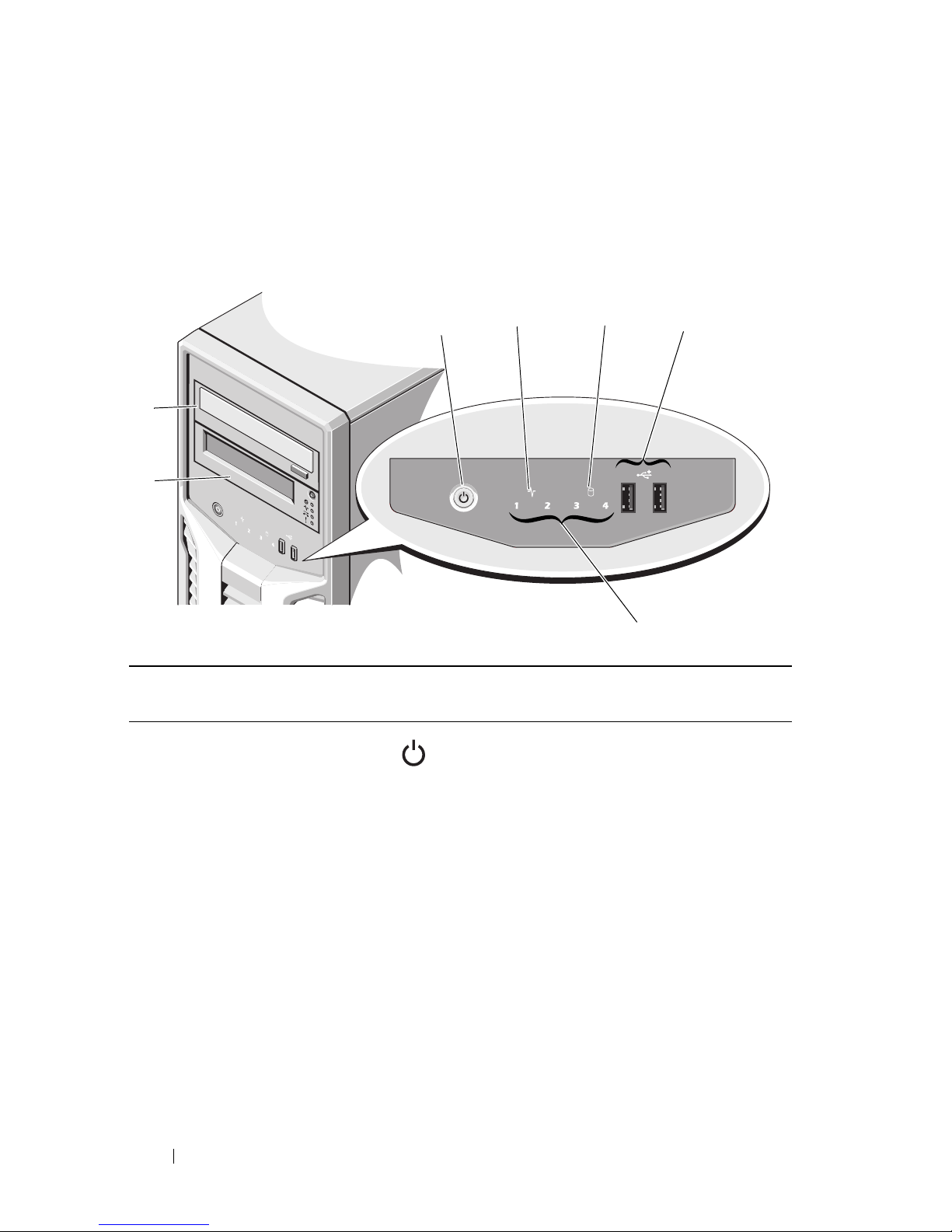
Front-Panel Features and Indicators
Figure 1-1. Front-Panel Features and Indicators
Item Indicator, Button, or
Connector
Icon Description
1Power-on indicator,
power button
The power-on indicator lights when the
system power is on.
The power button controls the DC
power supply output to the system.
NOTE: When powering on the system, the
video monitor can take from several
seconds to over 2 minutes to display an
image, depending on the amount of
memory installed in the system.
NOTE: On ACPI-compliant operating
systems, turning off the system using the
power button causes the system to
perform a graceful shutdown before
power to the system is turned off.
1
5
23
4
7
6

About Your System 11
2 System health
indicator
The system health indicator blinks
amber when a system fault is detected.
3 Hard-drive activity
indicator
The hard drive activity indicator lights
up when the hard drive is in use.
4 USB connectors (2) Connect USB devices to the system. The
ports are USB 2.0-compliant.
5 Diagnostic indicator
lights (4)
The four diagnostic indicator lights
display error codes during system
startup. See "Diagnostic Lights" on
page 15.
6 Tape drive (optional) One optional half-height (using one
drive bay).
7 Optical drive
(optional)
One optional SATA DVD-ROM drive or
DVD+/-RW drive.
NOTE: DVD devices are data only.
Item Indicator, Button, or
Connector
Icon Description
12 About Your System
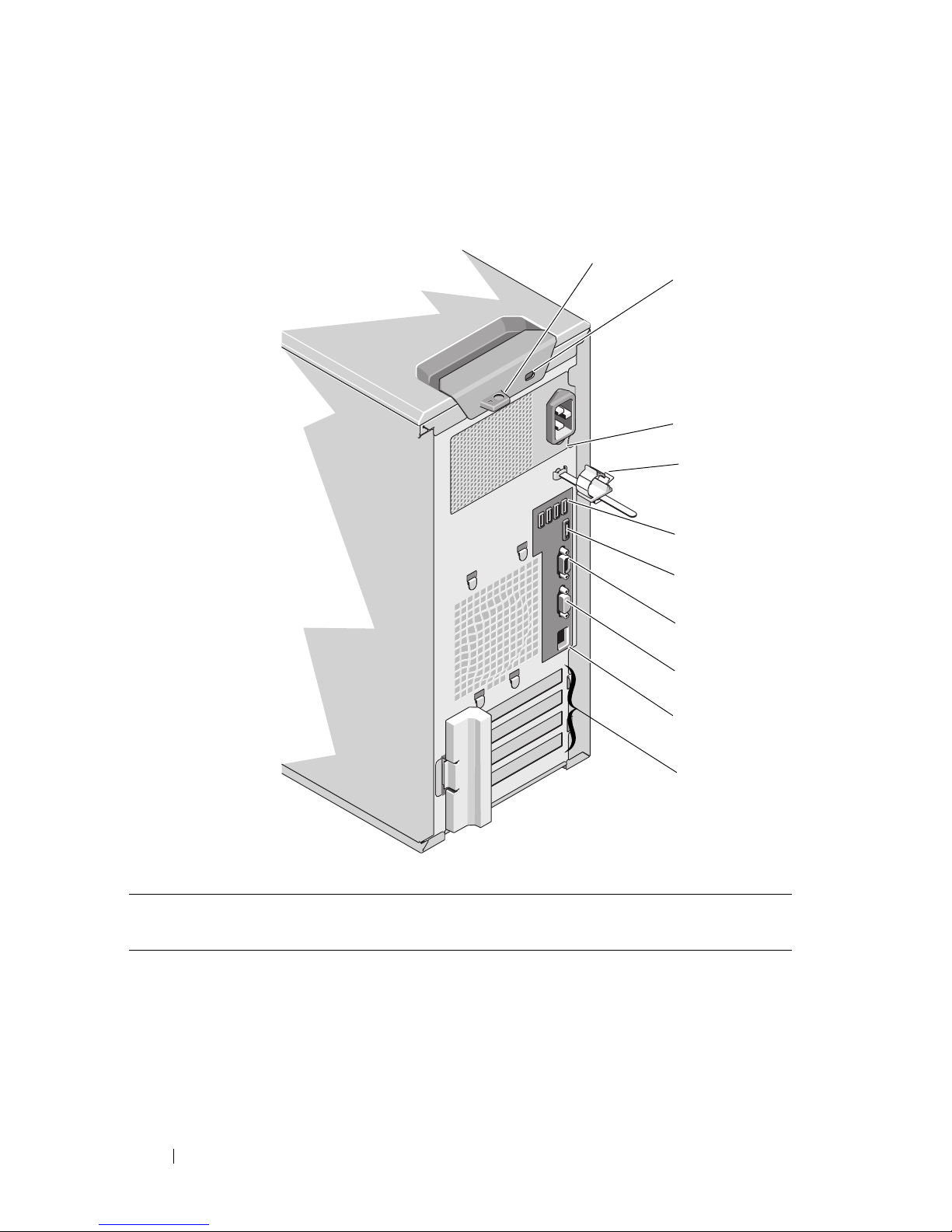
Back-Panel Features and Indicators
Figure 1-2. Back-Panel Features and Indicators
Item Indicator, Button, or
Connector
Icon Description
1 Padlock ring Locks the cover release latch.
2 Security cable slot Connects a cable lock to the system.
3 Power supply 305 W power supply.
4 Cable clasp Secures the power cable.
7
8
6
5
9
1
3
10
2
4

About Your System 13
Guidelines for Connecting External Devices
• Turn off power to the system and external devices before attaching a new
external device. Turn on any external devices before turning on the system
(unless the documentation for the device specifies otherwise).
• Ensure that the appropriate driver for the attached device has been
installed on the system.
• If necessary to enable ports on your system, use the System Setup program.
See "Using the System Setup Program and Boot Manager" on page 23.
5 USB connectors (4) Connect USB devices to the system. The
ports are USB 2.0-compliant.
6 eSATA connector Connects additional storage devices.
7 Serial connector Connects a serial device to the system.
8 Video connector Connects a VGA display to the system.
9 Ethernet connector Integrated 10/100/1000 NIC connector.
10 PCIe expansion card
slots (4)
Connects up to four PCI Express
expansion cards.
Item Indicator, Button, or
Connector
Icon Description
14 About Your System
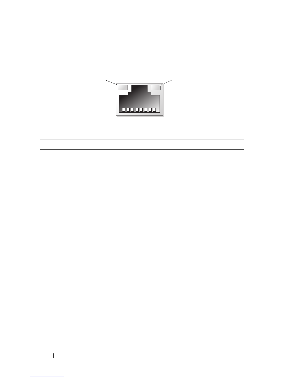
NIC Indicator Codes
Figure 1-3. NIC Indicator Codes
1 link indicator 2 activity indicator
Indicator Indicator Code
Link and activity indicators
are off
The NIC is not connected to the network.
Link indicator is green The NIC is connected to a valid network link at
1000 Mbps.
Link indicator is amber The NIC is connected to a valid network link at
10/100 Mbps.
Activity indicator is green
blinking
Network data is being sent or received.
1
2

About Your System 15
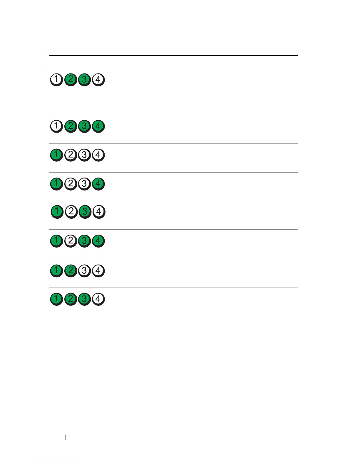
Diagnostic Lights
The four diagnostic indicator lights on the system front panel display error
codes during system startup. Table 1-1 lists the causes and possible corrective
actions associated with these codes. A highlighted circle indicates the light is
on; a non-highlighted circle indicates the light is off.
Table 1-1. Diagnostic Indicator Code
Code Causes Corrective Action
The system is in a normal
off condition or a possible
pre-BIOS failure has
occurred.
The diagnostic lights are
not lit after the system
successfully boots to the
operating system.
Plug the system into a working
electrical outlet and press the
power button.
The system is in a normal
operating condition after
POST.
Information only.
BIOS checksum failure
detected; system is in
recovery mode.
See "Getting Help" on page 123.
Possible processor failure. See "Troubleshooting the
Processor" on page 113.
Memory failure. See "Troubleshooting System
Memory" on page 107.
Possible expansion card
failure.
See "Troubleshooting Expansion
Cards" on page 112.
Possible video failure. See "Getting Help" on page 123.
16 About Your System
Hard drive failure. Ensure that the hard drives are
properly connected. See "Hard
Drives" on page 56 for
information on the drives
installed in your system.
Possible USB failure. See "Troubleshooting a USB
Device" on page 100.
No memory modules
detected.
See "Troubleshooting System
Memory" on page 107.
System board failure. See "Getting Help" on page 123.
Memory configuration
error.
See "Troubleshooting System
Memory" on page 107.
Possible system board
resource and/or system
board hardware failure.
See "Getting Help" on page 123.
Possible system resource
configuration error.
See "Getting Help" on page 123.
Other failure. Ensure that the optical drive and
hard drives are properly
connected. See "Troubleshooting
Your System" on page 99 for the
appropriate drive installed in your
system. If the problem persists,
see "Getting Help" on page 123.
Code Causes Corrective Action

About Your System 17
System Messages
System messages appear on the screen to notify you of a possible problem
with the system.
NOTE: If you receive a system message not listed in the table, check the
documentation for the application that is running when the message appears or the
operating system's documentation for an explanation of the message and
recommended action.
Message Causes Corrective Actions
BIOS
MANUFACTURING
MODE detected.
MANUFACTURING
MODE will be
cleared before
the next boot.
System reboot
required for
normal
operation.
System is in manufacturing
mode.
Reboot to take the system
out of manufacturing mode.
Caution!
NVRAM_CLR jumper
is installed on
system board.
Please run
SETUP.
NVRAM_CLR jumper is
installed in the clear setting.
CMOS has been cleared.
Move the NVRAM_CLR
jumper to the default
position (pins 3 and 5). See
Figure 6-1 for jumper
location. Restart the system
and re-enter the BIOS
settings. See "Using the
System Setup Program and
Boot Manager" on page 23.
Invalid
configuration
information please run SETUP
program.
An invalid system
configuration caused a
system halt.
Run the System Setup
program and review the
current settings. See "Using
the System Setup Program
and Boot Manager" on
page 23.
Keyboard
controller
failure.
Faulty keyboard controller;
faulty system board.
See "Getting Help" on
page 123.

18 About Your System
Keyboard data
line failure.
Keyboard stuck
key failure.
Keyboard cable connector is
improperly connected or the
keyboard is defective.
Reseat the keyboard cable. If
the problem persists, see
"Troubleshooting a USB
Device" on page 100.
Manufacturing
mode detected.
System is in manufacturing
mode.
Reboot to take the system
out of manufacturing mode.
Memory
Initialization
Warning: Memory
size may be
reduced.
Invalid memory
configuration. The system
will run but with less
memory than is physically
available.
Ensure that the memory
modules are installed in a
valid configuration. See
"General Memory Module
Installation Guidelines" on
page 73.
No boot device
available.
Faulty or missing optical
drive subsystem, hard drive,
or hard-drive subsystem, or
no bootable USB key
installed.
Use a bootable USB key, CD,
or hard drive. If the problem
persists, see
"Troubleshooting a USB
Device" on page 100,
"Troubleshooting an Optical
Drive" on page 109, and
"Troubleshooting a Hard
Drive" on page 111. See
"Using the System Setup
Program and Boot Manager"
on page 23 for information
on setting the order of boot
devices.
PCI BIOS failed
to install.
PCIe device BIOS (Option
ROM) checksum failure
detected during shadowing.
Cables to expansion card
loose; faulty or improperly
installed expansion card.
Reseat the expansion card.
Ensure that all appropriate
cables are securely connected
to the expansion card. If the
problem persists, see
"Troubleshooting Expansion
Cards" on page 112.
Message Causes Corrective Actions

About Your System 19
PCIe Training
Error: Expected
Link Width is x,
Actual Link
Width is y.
Faulty or improperly
installed PCIe card in the
specified slot.
Reseat the PCIe card in the
specified slot number. See
"Troubleshooting Expansion
Cards" on page 112. If the
problem persists, see
"Getting Help" on page 123.
SATA Portx
device not
found.
There is no device connected
to the specified SATA port.
Information only.
SATA port x
device autosensing error.
SATA port x
device
configuration
error.
SATA port x
device error.
The drive connected to the
specified SATA port is faulty.
Replace the faulty drive.
The amount of
system memory
has changed.
Memory has been added or
removed or a memory
module may be faulty.
If memory has been added or
removed, this message is
informative and can be
ignored. If memory has not
been added or removed,
check the SEL to determine
if single-bit or multi-bit
errors were detected and
replace the faulty memory
module. See
"Troubleshooting System
Memory" on page 107.
Time-of-day not
set - please run
SETUP program.
Incorrect Time or Date
settings; faulty system
battery.
Check the Time and Date
settings. See "Using the
System Setup Program and
Boot Manager" on page 23. If
the problem persists, replace
the system battery. See
"System Memory" on
page 73.
Message Causes Corrective Actions

20 About Your System
Warning Messages
A warning message alerts you to a possible problem and prompts you to
respond before the system continues a task. For example, before you format a
hard drive, a message warns you that you may lose all data on the hard drive.
Warning messages usually interrupt the task and require you to respond by
typing y (yes) or n (no).
NOTE: Warning messages are generated by either the application or the operating
system. For more information, see the documentation that accompanied the
operating system or application.
Diagnostics Messages
The system diagnostic utilities may issue messages if you run diagnostic tests
on your system. See "Running the System Diagnostics" on page 115 for more
information about system diagnostics.
Alert Messages
Systems management software generates alert messages for your system. Alert
messages include information, status, warning, and failure messages for drive,
temperature, fan, and power conditions. For more information, see the
systems management software documentation.
Timer chip
counter 2
failed.
Faulty system board. See "Getting Help" on
page 123.
TPM failure. A TPM function has failed. See "Getting Help" on
page 123.
Warning! No
micro code
update loaded
for processor n.
Micro code update failed. Update the BIOS firmware.
See "Getting Help" on
page 123.
NOTE: For the full name of an abbreviation or acronym used in this table, see the
Glossary
on support.dell.com/manuals.
Message Causes Corrective Actions

About Your System 21
Other Information You May Need
WARNING: See the safety and regulatory information that shipped with your
system. Warranty information may be included within this document or as a
separate document.
•The
Getting Started Guide
provides an overview of system features, setting
up your system, and technical specifications.
• Any media that ships with your system that provides documentation and
tools for configuring and managing your system, including those
pertaining to the operating system, system management software, system
updates, and system components that you purchased with your system.
NOTE: Always check for updates on support.dell.com/manuals and read the
updates first because they often supersede information in other documents.

22 About Your System

Using the System Setup Program and Boot Manager 23
2
Using the System Setup Program
and Boot Manager
The System Setup program is the BIOS program that enables you to manage
your system hardware and specify BIOS-level options. From the System Setup
program, you can:
• Change the NVRAM settings after you add or remove hardware
• View the system hardware configuration
• Enable or disable integrated devices
• Set performance and power management thresholds
• Manage system security
Choosing the System Boot Mode
The System Setup program also enables you to specify the boot mode for
installing your operating system:
• BIOS boot mode (the default) is the standard BIOS-level boot interface.
• UEFI boot mode is an enhanced 64-bit boot interface based on Unified
Extensible Firmware Interface (UEFI) specifications that overlays the
system BIOS. See "Entering the UEFI Boot Manager" on page 35 for more
information on this interface.
You must select the boot mode in the Boot Mode field of the "Boot Settings
Screen" on page 29 of the System Setup program. Once you specify the boot
mode, the system boots in the specified boot mode and you proceed then to
install your operating system from that mode. Thereafter, you must boot the
system to the same boot mode (BIOS or UEFI) to access the installed
operating system. Trying to boot the operating system from the other boot
mode will cause the system to halt immediately at startup.
NOTE: Operating systems must be UEFI-compatible (for example, Microsoft
Windows Server 2008 x64 version) to be installed from the UEFI boot mode. DOS and
32-bit operating systems do not support UEFI and can only be installed from the
BIOS boot mode.

24 Using the System Setup Program and Boot Manager
Entering the System Setup Program
1
Turn on or restart your system.
2
Press <F2> immediately after you see the following message:
<F2> = System Setup
If your operating system begins to load before you press <F2>, allow the
system to finish booting, and then restart your system and try again.
Responding to Error Messages
If an error message appears while the system is booting, make a note of the
message. See "System Messages" on page 17 for an explanation of the message
and suggestions for correcting errors.
NOTE: After installing a memory upgrade, it is normal for your system to display a
message the first time you start your system.
Using the System Setup Program Navigation Keys
NOTE: For most of the options, any changes that you make are recorded but do not
take effect until you restart the system.
Keys Action
Up arrow Moves to the previous field.
Down arrow or <Tab> Moves to the next field.
<Enter>, Spacebar, <+>, or
<
–>
Cycles through the settings in a field. In many
fields, you can also type the appropriate value.
<Esc> Exits the System Setup program and restarts the
system if any changes were made.
<F1> Displays the System Setup program's help file.
Using the System Setup Program and Boot Manager 25
System Setup Options
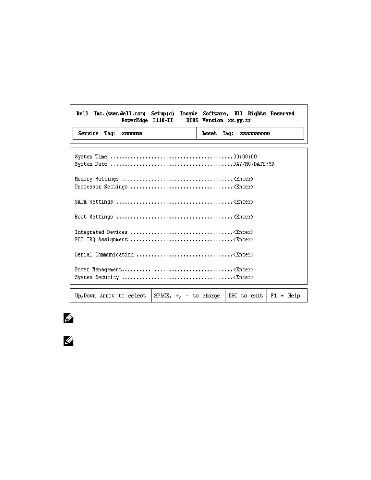
Main Screen
NOTE: The options for the System Setup program change based on the system
configuration.
NOTE: The System Setup program defaults are listed under their respective options
in the following sections, where applicable.
Option Description
System Time Sets the time on the system's internal clock.
System Date Sets the date on the system's internal calendar.
Memory Settings Displays information related to installed memory. See
"Memory Settings Screen" on page 27.

26 Using the System Setup Program and Boot Manager
Processor Settings Displays information related to the processor (speed,
cache size, and so on). See "Processor Settings Screen"
on page 27.
SATA Settings Displays a screen to enable or disable the integrated
SATA controller and ports. See "SATA Settings Screen"
on page 28.
Boot Settings Displays a screen to specify the boot mode (BIOS or
UEFI). For BIOS boot mode, you can also specify the
boot devices. See "Boot Settings Screen" on page 29.
Integrated Devices Displays a screen to enable or disable integrated device
controllers and ports, and to specify related features
and options. See "Integrated Devices Screen" on
page 29.
PCI IRQ Assignment Displays a screen to change the IRQ assigned to each of
the integrated devices on the PCI bus, and any installed
expansion card that requires an IRQ. See "PCI IRQ
Assignments Screen" on page 30.
Serial Communication Displays a screen to enable or disable the serial ports
and specify related features and options. See "Serial
Communication Screen" on page 31.
Power Management Enables you to manage power usage of the processor,
fans, and memory modules with preconfigured or
customized settings. See "Power Management Screen"
on page 32.
System Security Displays a screen to configure the system password and
setup password features. See "System Security Screen"
on page 33, "Using the System Password" on page 38,
and "Using the Setup Password" on page 40 for
more information.
Keyboard NumLock
(On default)
Determines whether your system starts up with the
NumLock mode activated on 101- or 102-key keyboards
(does not apply to 84-key keyboards).
Option Description

Using the System Setup Program and Boot Manager 27
Memory Settings Screen
Processor Settings Screen
Report Keyboard Errors
(
Report
default)
Enables or disables reporting of keyboard errors during
the POST. Select Report for host systems that have
keyboards attached. Select Do Not Report to suppress
all error messages relating to the keyboard or keyboard
controller during POST. This setting does not affect the
operation of the keyboard itself if a keyboard is attached
to the system.
F1/F2 Prompt on Error
(Enabled default)
Enables the system to halt on errors during POST,
which allows the user to observe events that may scroll
by unnoticed during normal POST. The user can press
<F1> to continue or <F2> to enter the System Setup
program.
CAUTION: When setting this option to Disabled,
the system does not halt if an error occurs during
POST. Any critical errors are displayed and logged
in the system event log.
Option Description
System Memory Size Displays the amount of system memory.
System Memory Type Displays the type of system memory.
System Memory Speed Displays the system memory speed.
Video Memory Displays the amount of video memory.
System Memory Testing
(Enabled default)
Specifies whether system memory tests are run at system
boot. Options are Enabled and Disabled.
Option Description
64-bit Specifies if the processor supports 64-bit extensions.
Core Speed Displays the processor clock speed.
Bus Speed Displays the processor bus speed.
Option Description

28 Using the System Setup Program and Boot Manager
SATA Settings Screen
Processor Family-ModelStepping
Displays the processor family and model.
Level 2 Cache Displays the level 2 cache size.
Level 3 Cache Displays the level 3 cache size.
Number of Cores Displays the number of cores of the processor.
Logical Processor
(Enabled default)
On processors that support Simultaneous MultiThreading (SMT) technology, each processor core
supports up to two logical processors. If this field is set to
Enabled, the BIOS reports both logical processors. If set
to Disabled, only one logical processor is monitored by
the BIOS.
Virtualization Technology
(Disabled default)
Enabled permits virtualization software to use the
virtualization technology incorporated in the processor.
NOTE: Disable this feature if your system will not be
running virtualization software.
Execute Disable
(Enabled default)
Enables or disables Execute Disable Memory Protection
Technology.
Number of Cores per
Processor
(All default)
If set to All, the maximum number of cores in each
processor is enabled.
Tu rb o M ode
(Enabled default)
If Turbo Boost technology is supported by the processor,
enables or disables Tu rb o M od e.
C States
(Enabled default)
When set to Enabled, the processor can operate in all
available power states.
Option Description
Embedded SATA
(AHCI default)
Allows the embedded SATA to be set to Off, ATA, AHCI,
or RAID modes.
Port A
(Auto default)
Auto enables BIOS support for the device attached to
SATA port A. Off disables BIOS support for the device.
Port B
(Off default)
Auto enables BIOS support for the device attached to
SATA port B. Off disables BIOS support for the device.
Option Description

Using the System Setup Program and Boot Manager 29
Boot Settings Screen
Integrated Devices Screen
Port C
(Off default)
Auto enables BIOS support for the device attached to
SATA port C. Off disables BIOS support for the device.
Port D
(Off default)
Auto enables BIOS support for the device attached to
SATA port D. Off disables BIOS support for the device.
Port E
(Auto default)
Auto enables BIOS support for the device attached to
SATA port E. Off disables BIOS support for the device.
eSATA port
(Auto default)
Auto enables BIOS support for the device attached to the
eSATA port. Off disables BIOS support for the device.
Option Description
Boot Mode
(BIOS default)
CAUTION: Switching the boot mode could prevent
the system from booting if the operating system was
not installed in the same boot mode.
If the operating system supports Unified Extensible
Firmware Interface (UEFI), you can set this option to
UEFI. Setting this field to BIOS allows compatibility
with non-UEFI operating systems.
NOTE: Setting this field to UEFI disables the Boot
Sequence, Hard-Disk Drive Sequence, and USB Flash Drive
Emulation Type fields.
Boot Sequence Retry
(Disabled default)
If this field is enabled and the system has failed to boot,
the system re-attempts to boot after 30 seconds.
Option Description
User Accessible
USB Ports
(All Ports On default)
Enables or disables the user-accessible USB ports.
Options are All Ports On, Only Back Ports On, and All
Ports Off.
Internal USB Port
(On default)
Enables or disables the internal USB port.
Option Description

30 Using the System Setup Program and Boot Manager
PCI IRQ Assignments Screen
Embedded NIC1 and
NIC2
(Enabled default)
Enables or disables the operating system interface of the
NIC1 and NIC2 controllers. (The NICs may also be
accessed through the system’s management controller).
Embedded Gb NIC1
(Enabled with PXE
default)
PXE support allows the system to boot from the network.
Enabled with iSCSI Boot option is available if the NIC
on board supports iSCSI.
MAC Address Displays the MAC address for the NIC.
Embedded Gb NIC2
(Enabled default)
PXE support allows the system to boot from the network.
Enabled with iSCSI Boot option is available if the NIC
on board supports iSCSI.
MAC Address Displays the MAC address for the NIC.
OS Watchdog Timer
(Disabled default)
Sets a timer to monitor the operating system for activity,
and aids in recovery if the system stops responding.
When Enabled, the operating system is allowed to
initialize the timer. When Disabled, the timer is
not initialized.
NOTE: This feature is usable only with operating systems
that support WDAT implementations of the Advanced
Configuration and Power Interface (ACPI) 3.0b
specification.
Embedded Video
Controller
(Standard default)
Enables or disables BIOS support for the integrated
video controller.
NOTE: This field can be disabled only if an add-in video
card is present. If this field is disabled, remote access
features such as virtual KVM are not available.
Option Description
<PCIe device> Use the <+> and <-> keys to manually select an IRQ
for a given device, or select Default to allow the BIOS to
select an IRQ value at system startup.
Option Description
 Loading...