

Dell PowerEdge E02B, PowerEdge FM120x4 Owner's Manual

Dell PowerEdge FM120x4
Owner's Manual
Regulatory Model: E02B
Regulatory Type: E02B002

Notes, cautions, and warnings
NOTE: A NOTE indicates important information that helps you make better use of your computer.
CAUTION: A CAUTION indicates either potential damage to hardware or loss of data and tells you
how to avoid the problem.
WARNING: A WARNING indicates a potential for property damage, personal injury, or death.
Copyright © 2015 Dell Inc. All rights reserved. This product is protected by U.S. and international copyright and
intellectual property laws. Dell™ and the Dell logo are trademarks of Dell Inc. in the United States and/or other
jurisdictions. All other marks and names mentioned herein may be trademarks of their respective companies.
2015 - 09
Rev. A02

Contents
1 About your system................................................................................................ 7
Terms used in the document................................................................................................................7
Front-panel features and indicators.....................................................................................................8
Hard-drive/SSD indicator patterns..................................................................................................9
Node status indicators...................................................................................................................10
Using USB diskette or USB DVD/CD drives.........................................................................................11
Documentation matrix........................................................................................................................ 12
Accessing system information by using QRL............................................................................... 12
2 Performing initial system configuration........................................................ 14
Setting up your system........................................................................................................................14
Setting up and configuring the iDRAC IP address..............................................................................14
Logging in to iDRAC............................................................................................................................ 15
Installing the operating system........................................................................................................... 15
Managing your system remotely.........................................................................................................15
Downloading drivers and firmware.....................................................................................................15
3 Pre-operating system management applications........................................ 16
Navigation keys....................................................................................................................................16
About system setup............................................................................................................................. 17
Entering System Setup...................................................................................................................17
System Setup main screen............................................................................................................ 17
System BIOS screen.......................................................................................................................17
System Information screen........................................................................................................... 18
Memory Settings screen................................................................................................................18
Processor Settings screen............................................................................................................. 19
SATA Settings screen.....................................................................................................................19
Boot Settings screen......................................................................................................................19
Integrated Devices screen............................................................................................................ 20
Serial Communications screen.....................................................................................................20
System Profile Settings screen...................................................................................................... 21
System Security screen................................................................................................................. 22
Miscellaneous Settings screen......................................................................................................22
About Boot Manager...........................................................................................................................23
Entering the UEFI Boot Manager.................................................................................................. 23
Boot Manager screen....................................................................................................................23
UEFI Boot menu............................................................................................................................ 23
About Dell Lifecycle Controller.......................................................................................................... 24
3

Changing the boot order....................................................................................................................24
Choosing the system boot mode.......................................................................................................24
Assigning a system or setup password...............................................................................................24
Using your system password to secure your system........................................................................ 25
Deleting or changing an existing system and/or setup password....................................................26
Operating with a setup password enabled........................................................................................ 26
Embedded system management........................................................................................................27
iDRAC Settings utility...........................................................................................................................27
Entering the iDRAC Settings utility................................................................................................27
Processor core licensing.....................................................................................................................27
Networking configurations.................................................................................................................28
Standard configuration................................................................................................................. 28
Network adapter isolation configuration..................................................................................... 29
Isolated networks configuration...................................................................................................29
Enhanced network adapter isolation configuration.................................................................... 30
4 Installing sled components.............................................................................. 33
Recommended tools.......................................................................................................................... 33
Removing the sled...............................................................................................................................33
Installing the sled................................................................................................................................ 34
Inside the sled......................................................................................................................................35
Cable cover......................................................................................................................................... 36
Removing the cable cover............................................................................................................36
Installing the cable cover.............................................................................................................. 37
Cooling shroud................................................................................................................................... 38
Removing the cooling shroud...................................................................................................... 38
Installing the cooling shroud........................................................................................................ 39
System memory.................................................................................................................................. 39
General memory module installation guidelines.........................................................................40
Sample memory configurations....................................................................................................41
Removing memory modules.........................................................................................................41
Installing memory modules.......................................................................................................... 42
Hard drives/SSDs.................................................................................................................................44
Hard drive/SSD to node assignment............................................................................................ 44
Removing a hard drive/SSD.......................................................................................................... 45
Installing a hard drive/SSD............................................................................................................46
Shutdown procedure for servicing a hard drive/SSD.................................................................. 46
Configuring the boot drive............................................................................................................47
Removing a 2.5 inch hard drive/SSD from a hard-drive/SSD carrier.......................................... 47
Installing a 2.5 inch hard drive/SSD in a hard-drive/SSD carrier................................................. 47
Removing a 1.8 inch SSD from the SSD carrier........................................................................... 48
Installing a 1.8 inch SSD in the SSD carrier.................................................................................. 48
4

Hard-drive/SSD backplane................................................................................................................. 48
Removing the hard-drive/SSD backplane....................................................................................49
Installing the hard-drive/SSD backplane......................................................................................50
SSD cage assembly............................................................................................................................. 50
Removing the SSD cage assembly............................................................................................... 50
Installing the SSD cage assembly..................................................................................................51
Easy restore module............................................................................................................................51
Replacing the easy restore module.............................................................................................. 51
System battery.....................................................................................................................................52
Replacing the system battery........................................................................................................52
System board.......................................................................................................................................54
Removing the system board.........................................................................................................54
Installing the system board........................................................................................................... 55
Control panel...................................................................................................................................... 56
Removing the control panel......................................................................................................... 56
Installing the control panel........................................................................................................... 57
5 Troubleshooting your system.......................................................................... 59
Safety first—for you and your system.................................................................................................59
Troubleshooting system memory...................................................................................................... 59
Troubleshooting hard drives.............................................................................................................. 60
Troubleshooting USB devices............................................................................................................ 60
Troubleshooting the system board.................................................................................................... 61
Troubleshooting the system battery...................................................................................................61
System messages................................................................................................................................ 62
Warning messages........................................................................................................................ 62
Diagnostic messages.....................................................................................................................62
Alert messages...............................................................................................................................62
6 Using system diagnostics..................................................................................63
Dell Embedded System Diagnostics...................................................................................................63
When to use the Embedded System Diagnostics........................................................................63
Running the Embedded System Diagnostics...............................................................................63
Running Embedded System Diagnostics from an external media..............................................63
System diagnostics controls.........................................................................................................64
7 Jumpers and connectors.................................................................................. 65
System board jumper settings............................................................................................................65
System board connectors.................................................................................................................. 66
Disabling a forgotten password..........................................................................................................67
8 Technical specifications....................................................................................68
5

Dimensions and weight...................................................................................................................... 68
Processor specifications.....................................................................................................................68
Memory specifications........................................................................................................................68
Drive specifications.............................................................................................................................68
Connectors specifications..................................................................................................................69
Video specifications............................................................................................................................69
Battery specifications..........................................................................................................................69
Expanded operating temperature...................................................................................................... 69
Environmental specifications..............................................................................................................70
9 Getting help.........................................................................................................73
Contacting Dell....................................................................................................................................73
Accessing system information by using QRL.....................................................................................73
Locating your system Service Tag......................................................................................................74
6

About your system
This document provides information on the Dell PowerEdge FM120x4 systems, installed in the Dell
PowerEdge FX2 enclosure. For information on the enclosure components, including shared resources
like the power supplies, Chassis Management Controller (CMC), cooling fans, and I/O modules, see the
Dell PowerEdge FX2 and FX2s Enclosure Owner’s Manual at Dell.com/poweredgemanuals.
Terms used in the document
Table 1. Terms and description
Term Description
Enclosure Refers to the PowerEdge FX2 enclosure.
Sled or system Refers to the PowerEdge FM120x4 system.
Nodes Refer to the four compute nodes (Intel Atom
C2000 processors) in the FM120x4 sled. Each node
functions as an independent server and can be
remotely managed through individual iDRACs.
Hard-drive/SSD bay Refers to the slots on the sled front panel in which
the hard drives/SSDs are installed.
1
Warm swap A component is considered warm swap if the node
associated with the component must be turned off
before adding or replacing the component.
However, the sled and the rest of the nodes remain
powered on.
Hot swap A component is considered hot swap if it can be
removed or installed while the nodes and the sled
are powered on.
7
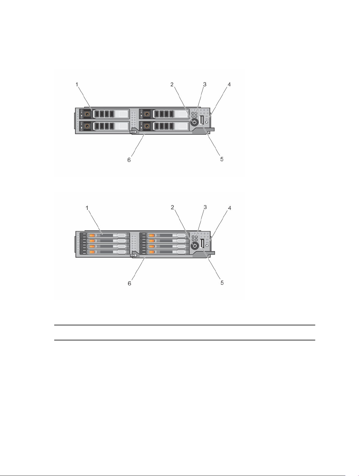
Front-panel features and indicators
Figure 1. Front-panel features and indicators — 2.5 inch hard-drive/SSD system
Figure 2. Front-panel features and indicators — 1.8 inch SSD system
Table 2. Front-panel features and indicators
Item Indicator, Button, or
Connector
1 Hard drives/SSDs
8
Icon Description
2.5 inch harddrive/SSD system
Four 2.5 inch warmswap SATA hard drives
or SATA SSDs.
Item Indicator, Button, or
Connector
Icon Description
1.8 inch SSD
system
2 Sled power-on
indicator, power
button
3 Node status indicators Provide information about the status of the
4 USB select button Allows you to assign the USB port to a
5 USB connector Allows a USB device to be connected to the
6 Sled handle Used to slide the sled out of the enclosure.
The power-on indicator lights when the sled
power is on. The power button controls the
power supply output to the system.
four nodes in the sled.
particular node in the sled.
system.
Eight 1.8 inch hotswap SATA SSDs.
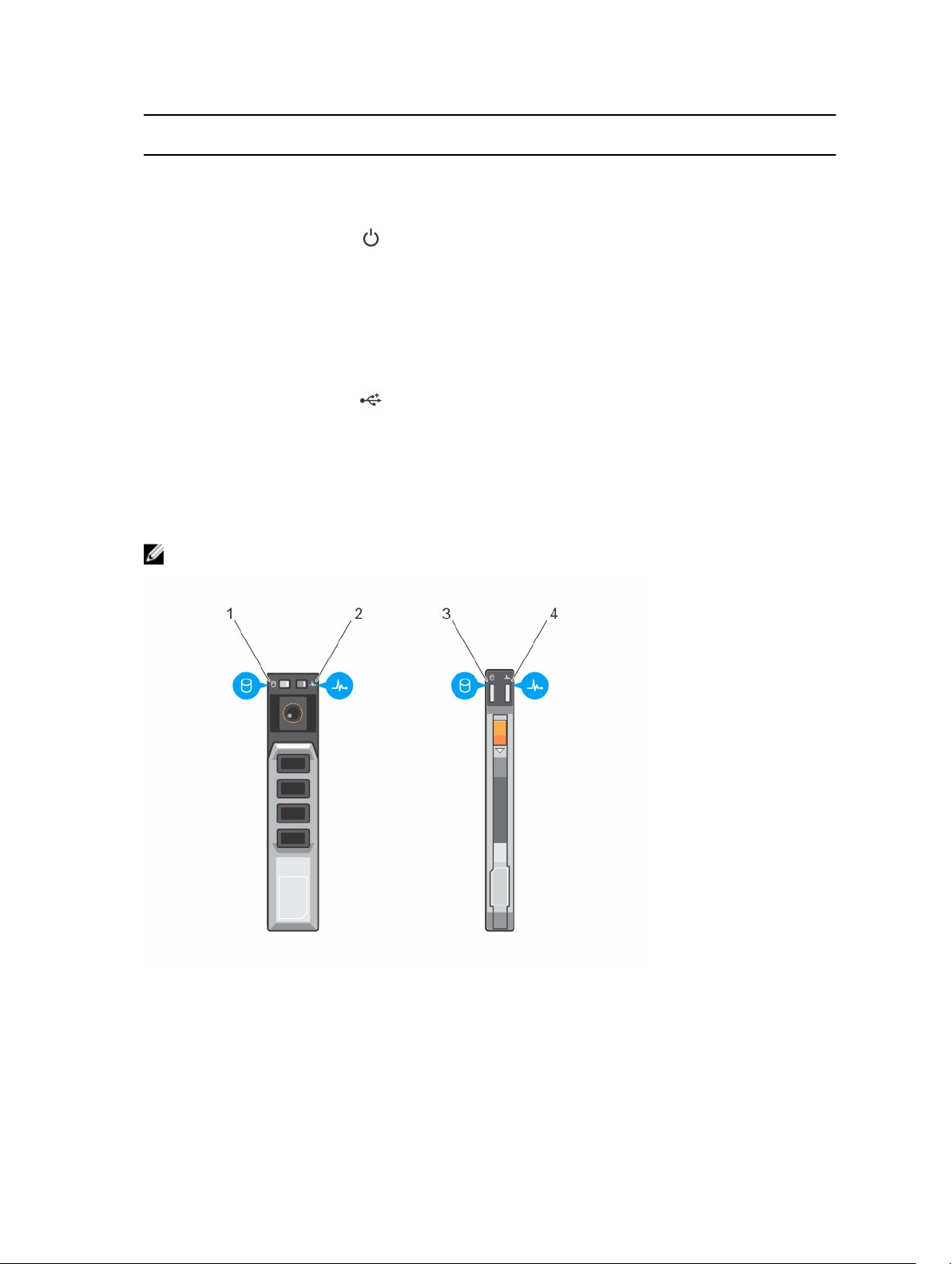
Hard-drive/SSD indicator patterns
The hard-drive/SSD indicators display different patterns as drive events occur in the system.
NOTE: The sled must have a hard drive/SSD or a hard-drive/SSD blank installed in each drive bay.
Figure 3. Hard-drive/SSD indicators
1. drive activity indicator (green) — 2.5 inch hard
drive/SSD
3. drive activity indicator (green) — 1.8 inch SSD 4. drive status indicator (green and amber) —
2. drive status indicator (green and amber) —
2.5 inch hard drive/SSD
1.8 inch SSD
9
NOTE: If the drive is in Advanced Host Controller Interface (AHCI) mode, the status LED (on the
right side) does not function and remains off.
Table 3. Hard-drive/SSD indicator patterns
Drive-Status Indicator Pattern Condition
Blinks green two times per second Identifying drive or preparing for removal
Off Drive ready for insertion or removal
NOTE: The drive status indicator remains off
until all drives are initialized after system
power is applied. Drives are not ready for
insertion or removal during this time.
Blinks green, amber, and turns off Drive predicted failure
Blinks amber four times per second Drive failed
Blinks green slowly Drive rebuilding
Steady green Drive online
Blinks green three seconds, amber three seconds,
and turns off six seconds
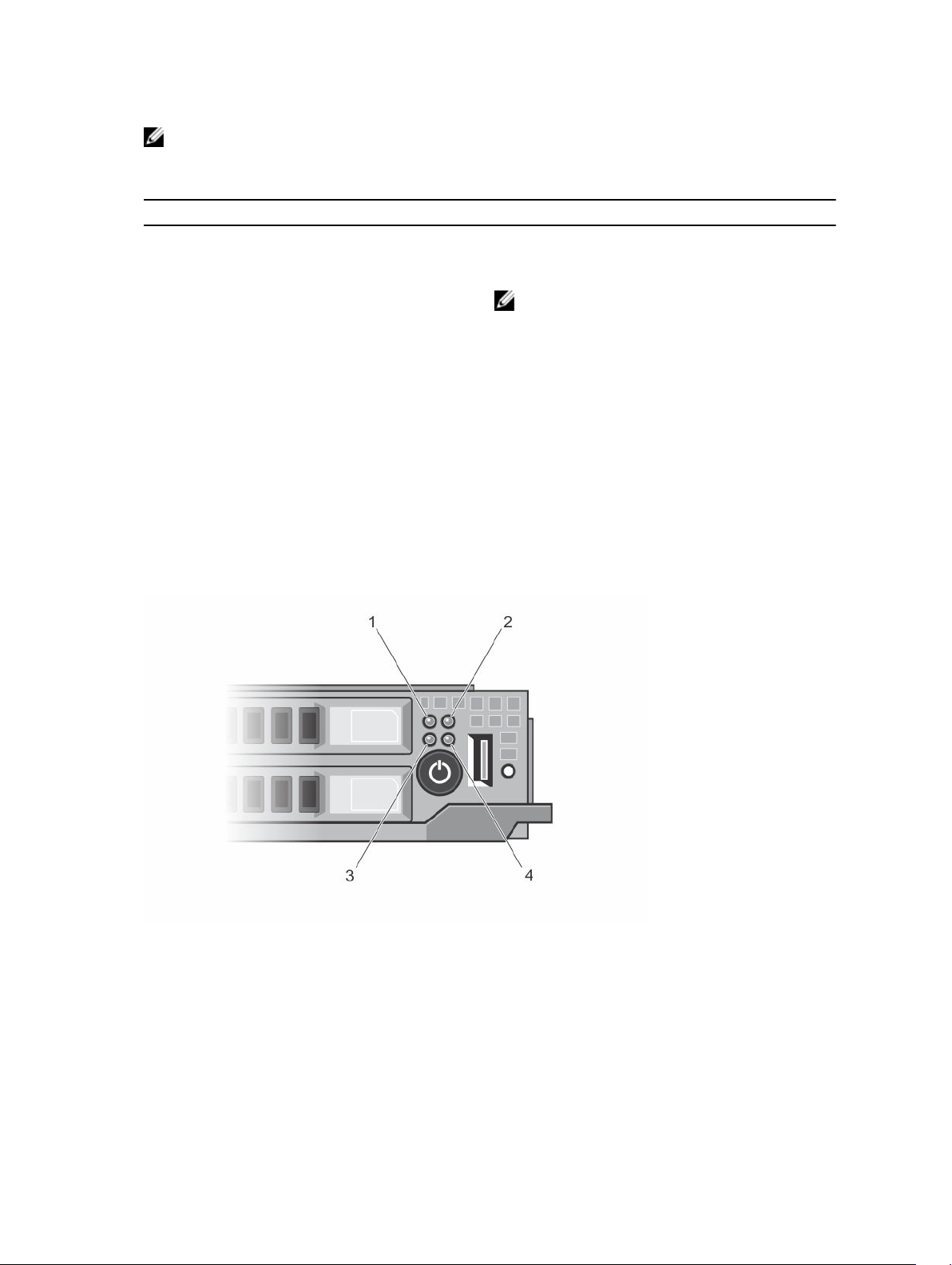
Node status indicators
Figure 4. Node status indicators
Rebuild aborted
1. node A status indicator 2. node B status indicator
3. node C status indicator 4. node D status indicator
There is an indicator for each of the four nodes, on the front panel of the sled. The node status indicators
provide the following information.
10

Indicator Pattern Description
Off The node is powered off.
Solid blue The node is powered on.
Blinking blue The node is identified.
NOTE: When a node is identified, the status indicator of the hard drive(s)/
SSD(s) associated with the node blinks, and the activity indicator of the hard
drive(s)/SSD(s) is off for the duration of the node identification blink pattern.
Rapid blinking blue The indicator blinks blue rapidly, when KVM or USB is selected on the node.
NOTE: When the USB select button on the sled is pressed, the status
indicators of the unselected nodes do not blink for the duration of the
selected node status indicator blink.
Blue fade on/fade
off
Amber The node is in a fault condition.
The node is requesting power on from the CMC.
NOTE: When any node in the sled is in this state, the sled power indicator also
blinks along with the node indicator, at the same speed.
NOTE: The indicator blinks amber if in fault condition, even when the node is
powered off.
Using USB diskette or USB DVD/CD drives
The sled has a USB port on the front, which allows you to connect a USB diskette drive, USB DVD/CD
drive, keyboard, or mouse. The sled USB port is shared between the four nodes in the system. The USB
drives can be used to configure the sled.
NOTE: Your sled supports only Dell-branded USB 2.0 drives.
NOTE: To designate the drive as the boot drive, connect the USB drive, restart the system, then
enter the System Setup and set the drive as first in the boot sequence. The USB device is displayed
in the boot order setup screen only if it is attached to the system before you run the System Setup.
You can also select the boot device by pressing F11 during system start-up and selecting a boot
device for the current boot sequence.
The USB select button on the sled front panel allows selection of the shared USB port between the four
nodes. When a node is selected for connection to the sled USB port by pressing the USB select button,
the node status indicator of the selected node blinks rapid blue. If the USB select button is pressed again
while a node indicator is blinking rapid blue, the next node is selected for connection to the USB port.
The status indicator of the newly selected node blinks rapid blue.
NOTE: Node A is the default node for USB port connection.
11

Documentation matrix
The documentation matrix provides information on documents that you can refer to for setting up and
managing your system.
Table 4. Documentation matrix
To... See the...
Install your system into a rack Rack documentation included with your rack
solution
Set up your system and know the system technical
specifications
Install the operating system Operating system documentation at Dell.com/
Getting Started With Your System that shipped with
your system or see Dell.com/poweredgemanuals
operatingsystemmanuals
Get an overview of the Dell Systems Management
offerings
Configure and log in to iDRAC, set up managed
and management system, know the iDRAC
features, and troubleshoot by using iDRAC
Know about the RACADM subcommands and
supported RACADM interfaces
Launch, enable, and disable Dell Lifecycle
Controller, know the features, use and
troubleshoot Dell Lifecycle Controller
Use Dell Lifecycle Controller Remote Services Dell Lifecycle Controller Remote Services Quick
Set up, use, and troubleshoot OpenManage Server
Administrator
Install, use, and troubleshoot OpenManage
Essentials
Know the features of the storage controller cards,
deploy the cards, and manage the storage
subsystem
Dell OpenManage Systems Management Overview
Guide at Dell.com/openmanagemanuals >
OpenManage software
Integrated Dell Remote Access Controller User's
Guide at Dell.com/idracmanuals
RACADM Command Line Reference Guide for
iDRAC at Dell.com/idracmanuals
Dell Lifecycle Controller User’s Guide at Dell.com/
idracmanuals
Start Guide at Dell.com/idracmanuals
Dell OpenManage Server Administrator User’s
Guide at Dell.com/openmanagemanuals >
OpenManage Server Administrator
Dell OpenManage Essentials User’s Guide at
Dell.com/openmanagemanuals > OpenManage
Essentials
Storage controller documentation at Dell.com/
storagecontrollermanuals
Check the event and error messages generated by
the system firmware and agents that monitor
system components
Dell Event and Error Messages Reference Guide at
Dell.com/openmanagemanuals > OpenManage
software
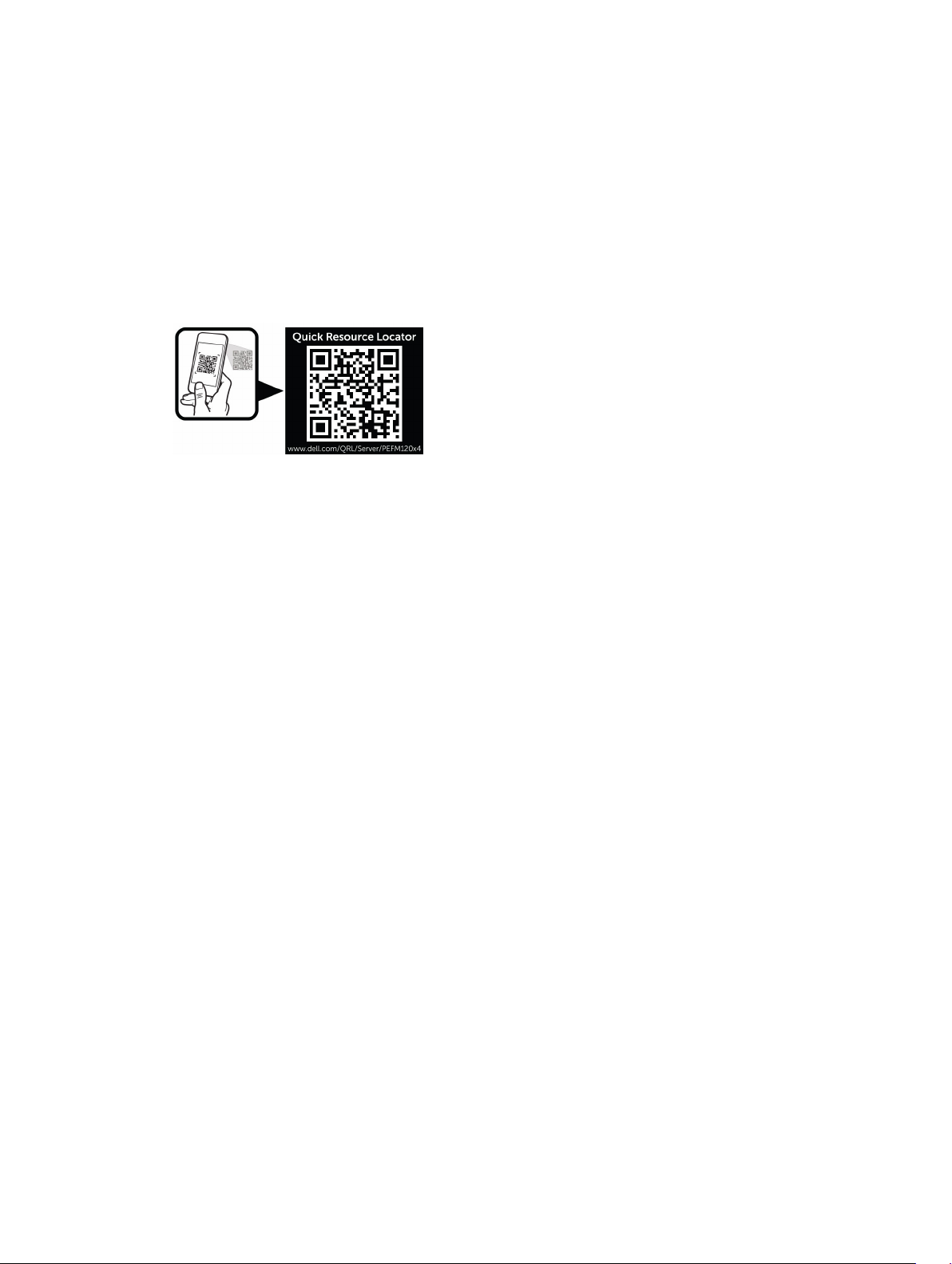
Accessing system information by using QRL
You can use the Quick Resource Locator (QRL) to get immediate access to the information about your
system.
Ensure that your smartphone or tablet has the QR code scanner installed.
12
The QRL includes the following information about your system:
• How-to videos
• Reference materials, including the Owner’s Manual, LCD diagnostics, and mechanical overview
• Your system service tag to quickly access your specific hardware configuration and warranty
information
• A direct link to Dell to contact technical support and sales teams
1. Go to Dell.com/QRL and navigate to your specific product or
2. Use your smartphone or tablet to scan the model-specific Quick Resource (QR) code located in the
following image or on your Dell PowerEdge system:
13

Performing initial system configuration
After you receive your PowerEdge system, you must set up your system in the enclosure, install the
operating system if it is not pre-installed, and set up and configure the system iDRAC IP address.
Setting up your system
1. Unpack the sled.
2. Remove the I/O connector cover from the sled connectors.
CAUTION: While installing the sled, ensure that it is properly aligned with the slot on the
enclosure to prevent damage to the sled connectors.
3. Install the sled in the enclosure.
4. Turn on the enclosure.
NOTE: Wait for the chassis to initialize before you press the power button.
5. Turn on the sled by pressing the power button on the sled.
Alternatively, you can also turn on the sled by using:
• The sled iDRAC. For more information, see Logging in to iDRAC.
• The enclosure Chassis Management Controller (CMC), after the sled iDRAC is configured on the
CMC. For more information, see the CMC User’s Guide at Dell.com/esmmanuals.
2
Setting up and configuring the iDRAC IP address
You can set up the iDRAC IP address using one of the following interfaces:
• iDRAC Settings utility
• Dell Lifecycle Controller
• Dell Deployment Toolkit
• CMC Web interface
You can configure iDRAC using one of the following interfaces:
• iDRAC Web interface
• RACADM
• Remote services
• IPMI tool
For more information on setting up and configuring iDRAC, see the iDRAC User’s Guide at Dell.com/
esmmanuals.
14

Logging in to iDRAC
You can log in to iDRAC as an iDRAC user, a Microsoft Active Directory user, or a Lightweight Directory
Access Protocol (LDAP) user. You can also log in using Single Sign-On or Smart Card. The default user
name is root and password is calvin. For more information on logging in to iDRAC and iDRAC licenses,
see the iDRAC User’s Guide at Dell.com/esmmanuals.
You can also access iDRAC using RACADM. For more information, see the RACADM Reference Guide for
iDRAC and CMC available at Dell.com/esmmanuals.
Installing the operating system
You can install the supported operating system on the sled by using the following methods:
• Dell Systems Management Tools and Documentation media. See the operating system
documentation at Dell.com/operatingsystemmanuals.
• Dell Lifecycle Controller. See the Lifecycle Controller documentation at Dell.com/esmmanuals.
• Dell OpenManage Deployment Toolkit. See the OpenManage documentation at Dell.com/
openmanagemanuals.
For information on the list of operating systems supported on your system, see the operating system’s
support matrix at Dell.com/ossupport.
Managing your system remotely
To perform out-of-band systems management by using iDRAC, you must configure iDRAC for remote
accessibility, set up the management station and managed system, and configure the supported Web
browsers. For more information, see the iDRAC User’s Guide at Dell.com/esmmanuals.
You can also remotely monitor and manage the sleds from a single workstation, using the Dell
OpenManage Server Administrator (OMSA) software and OpenManage Essentials (OME) systems
management console. For more information, see Dell.com/openmanagemanuals.
Downloading drivers and firmware
It is recommended that you download and install the latest BIOS, drivers, and systems management
firmware on your system.
Ensure that you clear the web browser cache.
1. Go to Dell.com/support/drivers.
2. In the Product Selection section, enter the Service Tag of your system in the Service Tag or Express
Service Code field.
NOTE: If you do not have the Service Tag, select Automatically detect my Service Tag for me
to enable the system to automatically detect your service tag, or select your product from the
Product Selection page.
3. Click Get drivers and downloads.
The drivers that are applicable to your selection are displayed.
4. Download the drivers that you need to a USB drive, CD, or DVD.
15

3
Pre-operating system management applications
The pre-operating system management applications for your system help you manage different settings
and features without booting to the operating system.
Your system has the following pre-operating system management applications:
• System Setup
• Boot Manager
• Dell Lifecycle Controller
• Preboot Execution Environment (PXE)
Navigation keys
The navigation keys can help you quickly access the pre-operating system management applications.
Key Description
F2 Enables you to enter System Setup.
F10 Enables you to enter system services and starts Lifecycle Controller.
F11 Enables you to enter Boot Manager.
F12 Enables you to enter PXE Boot.
Page Up Enables you to move to the previous screen.
Page Down Enables you to move to the next screen.
Up arrow Enables you to move to the previous field.
Down arrow Enables you to move to the next field.
Enter Enables you to type a value in the selected field (if applicable).
Spacebar Enables you to expand or collapse a drop-down list, if applicable.
Tab Enables you to move to the next menu item.
NOTE: This feature is applicable only for the standard graphic browser.
Esc Enables you to move to the previous page until you view the main screen. Pressing
Esc in the main screen exits System BIOS, iDRAC Settings, Device Settings, or
Service Tag Settings, and proceeds with system boot.
F1 Displays the system setup help.
16

About system setup
By using the System Setup screen, you can configure the BIOS settings, iDRAC settings, and device
settings of your system.
NOTE: Help text for the selected field is displayed in the graphical browser by default. To view the
help text in the text browser, press F1.
You can access system setup in two ways:
• Standard graphical browser — The browser is enabled by default.
• Text Browser — The browser is enabled by using Console Redirection.
Entering System Setup
1. Turn on or restart your system.
2. Press F2 immediately after you see the following message:
F2 = System Setup
If your operating system begins to load before you press F2, allow the system to finish booting, and
then restart your system and try again.
System Setup main screen
NOTE: Press Alt+F to reset the BIOS or UEFI settings to their default settings.
Menu Item Description
System BIOS This option is used to view and configure BIOS settings.
iDRAC Settings This option is used to view and configure iDRAC settings.
Device Settings This option is used to view and configure device settings.
System BIOS screen
NOTE: The options for System Setup change based on the system configuration.
NOTE: System Setup defaults are listed under their respective options in the following sections,
where applicable.
Menu Item Description
System
Information
Memory Settings Displays information and options related to installed memory.
Processor Settings Displays information and options related to the processor such as speed, cache
SATA Settings Displays options to enable or disable the integrated SATA controller and ports.
Boot Settings Displays options to specify the boot mode (BIOS or UEFI). Enables you to modify
Displays information about the system, such as the system model name, BIOS
version, Service Tag, and so on.
size, and so on.
UEFI and BIOS boot settings.
17

Menu Item Description
Integrated Devices Displays options to enable or disable integrated device controllers and ports, and to
specify related features and options.
Serial
Communication
System Profile
Settings
System Security Displays options to configure the system security settings like, system password,
Miscellaneous
Settings
Displays options to enable or disable the serial ports and specify related features
and options.
Displays options to change the processor power management settings, memory
frequency, and so on.
setup password, TPM security, and so on. It also enables or disables support for
local BIOS update and the power button on the system.
Displays options to change the system date, time, and so on.
System Information screen
Menu Item Description
System Model
Name
System BIOS
Version
System Service Tag Displays the system Service Tag.
System
Manufacturer
Displays the system model name.
Displays the BIOS version installed on the system.
Displays the name of system manufacturer.
System
Manufacturer
Contact
Information
System CPLD
Version
Displays the contact information of the system manufacturer.
Displays the system CPLD version.
Memory Settings screen
Menu Item Description
System Memory
Size
System Memory
Type
System Memory
Speed
System Memory
Voltage
Displays the amount of memory installed in the system.
Displays the type of memory installed in the system.
Displays the system memory speed.
Displays the system memory voltage.
18

Menu Item Description
Video Memory Displays the amount of video memory.
System Memory
Testing
Specifies whether system memory tests are run during system boot. Options are
Enabled and Disabled. By default, the System Memory Testing option is set to
Disabled.
Processor Settings screen
Menu Item Description
Virtualization
Technology
Execute Disable Allows you to enable or disable execute disable memory protection technology. By
Number of Cores
per Processor
Processor 64-bit
Support
Processor Core
Speed
Processor X
Family- ModelStepping
Allows you enable or disable the additional hardware capabilities provided for
virtualization. By default, the Virtualization Technology option is set to Enabled.
default, the Execute Disable option is set to Enabled.
Allows you to control the number of enabled cores in each processor. By default,
the Number of Cores per Processor option is set to All.
NOTE: The number of available cores varies, based on the core license. For
more information, see Processor Core Licensing.
Specifies if the processor(s) support 64-bit extensions.
Displays the maximum core frequency of the processor.
Displays the family and model number of each processor. A submenu displays the
brand name, core speed, the amount of cache memory, and the number of cores
of the processor(s).
SATA Settings screen
Menu Item Description
Embedded SATA Allows the embedded SATA to be set to Off, ATA, AHCI, or RAID modes. By default,
Embedded SATA is set to AHCI.
Port A Auto enables BIOS support for the device attached to SATA port A. Off disables
BIOS support for the device. By default, Port A is set to Auto.
Port B Auto enables BIOS support for the device attached to SATA port B. Off disables
BIOS support for the device. By default, Port B is set to Auto.
Boot Settings screen
Menu Item Description
Boot Mode Allows you to set the boot mode of the system.
CAUTION: Switching the boot mode may prevent the system from booting if
the operating system is not installed in the same boot mode.
19

Menu Item Description
If the operating system supports UEFI, you can set this option to UEFI. Setting this
field to BIOS allows compatibility with non-UEFI operating systems. By default, the
Boot Mode option is set to BIOS.
NOTE: Setting this field to UEFI disables BIOS Boot Settings menu. Setting this
field to BIOS disables the UEFI Boot Settings menu.
Boot Sequence
Retry
BIOS Boot Settings Allows you to enable or disable BIOS Boot options.
UEFI Boot Settings Allows you to enable or disable UEFI Boot options. The Boot options include IPv4
Allows you to enable or disable the boot sequence retry feature. If this field is
enabled and the system fails to boot, the system reattempts the boot sequence
after 30 seconds. By default, the Boot Sequence Retry option is set to Disabled.
NOTE: This option is enabled only if the boot mode is BIOS.
PXE and IPv6 PXE. By default, the UEFI PXE boot protocol is set to IPv4.
NOTE: This option is enabled only if the boot mode is UEFI.
Integrated Devices screen
Menu Item Description
User Accessible
USB Ports
Embedded NIC1
and NIC2
OS Watchdog
Timer
Allows you to set the user accessible ports. Selecting All Ports Off disables all USB
ports. By default, the User Accessible USB Ports option is set to All Ports On.
Allows you to enable or disable the Operating System interface of the embedded
NIC1 and NIC2 controller. By default, the Embedded NIC1 and NIC2 option is set
to Enabled.
Allows you to enable or disable the OS wacthdog timer. When this field is enabled,
the operating system initializes the timer and the OS watchdog timer helps in
recovering the operating system. By default, the OS Watchdog Timer option is set
to Disabled.
Serial Communications screen
Menu Item Description
Serial
Communication
Serial Port Address Allows you to set the port address for serial devices. By default, the Serial Port
Failsafe Baud Rate Displays the failsafe baud rate for console redirection. The BIOS attempts to
20
Allows you to enable the COM port or Console Redirection options.
Address option is set to COM1.
NOTE: Only Serial Device 2 can be used for Serial Over LAN (SOL). To use
console redirection by SOL, configure the same port address for console
redirection and the serial device.
determine the baud rate automatically. This failsafe baud rate is used only if the

Menu Item Description
attempt fails and the value must not be changed. By default, the Failsafe Baud Rate
option is set to 11520.
Remote Terminal
Type
Redirection After
Boot
Allows you to set the remote console terminal type. By default, the Remote
Terminal Type option is set to VT 100/VT220.
Allows you to enable or disable to the BIOS console redirection when the
operating system is loaded. By default, the Redirection After Boot option is set to
Enabled.
System Profile Settings screen
Menu Item Description
System Profile Allows you to set the system profile. If you set the System Profile option to a mode
other than Custom, the BIOS automatically sets the rest of the options. You can
only change the rest of the options if the mode is set to Custom. By default, the
System Profile option is set to Performance Per Watt Optimized (DAPC). DAPC is
Dell Active Power Controller.
NOTE: The following parameters are available only when the System Profile is
set to Custom.
CPU Power
Management
Memory
Frequency
Allows you to set the CPU power management. By default, the CPU Power
Management option is set to System DBPM (DAPC). DBPM is Demand-Based
Power Management.
Allows you to set the memory frequency. By default, the Memory Frequency
option is set to Maximum Performance.
Turbo Boost Allows you to enable or disable the processor to operate in turbo boost mode. By
default, the Turbo Boost option is set to Enabled.
C States Allows you to enable or disable the processor to operate in all available power
states. By default, the C States option is set to Enabled.
Monitor/Mwait Allows you to enable Monitor/Mwait instructions in the processor. By default, the
Monitor/Mwait option is set to Enabled for all system profiles, except Custom.
NOTE: This option can be disabled only if the C States option in Custom
mode is disabled.
NOTE: When C States is enabled in Custom mode, changing the Monitor/
Mwait setting does not impact system power/performance.
Memory Patrol
Scrub
Memory Refresh
Rate
Memory Operating
Voltage
Allows you to set the memory patrol scrub frequency. By default, the Memory
Patrol Scrub option is set to Standard.
Allows you to set the memory refresh rate. By default, the Memory Refresh Rate
option is set to 1x.
Allows you to set the DIMM voltage selection. When set to Auto, the system
automatically sets the system voltage to the optimal setting based on the DIMM
21

Menu Item Description
capacity and the number of DIMMs installed. By default, the Memory Operating
Voltage option is set to Auto.
Collaborative CPU
Performance
Control
When set to enabled, the CPU power management is controlled by the OS DBPM
and the System DBPM (DAPC). By default, the option is set to Disabled.
System Security screen
Menu Item Description
Intel AES-NI The Intel AES-In option improves the speed of applications by performing
encryption and decryption using the Advanced Encryption Standard set and is set
to Enabled by default.
System Password Allows you to set the system password. This option is read-only if the password
jumper is not installed in the system.
Setup Password Allows you to set the setup password. This option is read-only if the password
jumper is not installed in the system.
Password Status Allows you to lock the system password. By default, the Password Status option is
set to Unlocked.
AC Power
Recovery
Allows you to set how the system reacts after AC power is restored to the system.
By default, the AC Power Recovery option is set to Last.
Miscellaneous Settings screen
Menu Item Description
System Time Allows you to set the time on the system.
System Date Allows you to set the date on the system.
Asset Tag Displays the asset tag and allows you to modify it for security and tracking
purposes.
Keyboard
NumLock
Report Keyboard
Errors
F1/F2 Prompt on
Error
22
Allows you to set whether the system boots with the NumLock enabled or
disabled. By default the Keyboard NumLock is set to On.
NOTE: This field does not apply to 84-key keyboards.
Allows you to set whether keyboard-related error messages are reported during
system boot. By default, the Report Keyboard Errors field is set to Report.
Allows you to enable or disable the F1/F2 prompt on error. By default, F1/F2
Prompt on Error is set to Enabled.

About Boot Manager
Boot manager enables you to add, delete, and arrange boot options. You can also access System Setup
and boot options without restarting the system.
Entering the UEFI Boot Manager
NOTE: Operating systems must be 64-bit UEFI-compatible (for example, Microsoft Windows Server
2008 x64 version) to be installed from the UEFI boot mode. DOS and 32-bit operating systems can
only be installed from the BIOS boot mode.
The Boot Manager enables you to:
• Add, delete, and arrange boot options
• Access System Setup and BIOS-level boot options without rebooting
To enter the Boot Manager:
1. Turn on or restart your system.
2. Press F11 after you see the following message:
F11 = UEFI Boot Manager
If your operating system begins to load before you press F11, allow the system to finish booting, and
then restart your system and try again.
Boot Manager screen
Menu Item Description
Continue Normal
Boot
BIOS Boot Menu Displays the list of available BIOS boot options (marked with asterisks). Select the
UEFI Boot Menu Displays the list of available UEFI boot options (marked with asterisks). Select the
Driver Health
Menu
Launch System
Setup
System Utilities Enables you to access the BIOS Update File Explorer, run the Dell Diagnostics
The system attempts to boot to devices starting with the first item in the boot
order. If the boot attempt fails, the system continues with the next item in the boot
order until the boot is successful or no more boot options are found.
boot option you wish to use and press Enter.
boot option you wish to use and press Enter. The UEFI Boot Menu enables you to
Add Boot Option, Delete Boot Option, or Boot From File.
Displays a list of the drivers installed on the system and their health status.
Enables you to access the System Setup.
program, and reboot the system.
UEFI Boot menu
Menu Item Description
Boot From File Sets a one-time boot option not included in the boot option list.
23
 Loading...