

Page 1

Dell PowerEdge
C8000, C8220, C8220X,
and C8000XD
Getting Started
With Your System
Mise en route de votre système
Introdução ao uso do seu sistema
Introducción al sistema
FILE LOCATION: J:\DL\DL133448\DTP\P06HNfc4.fm
Regulatory Model: B10S, B05B, and B06B
Regulatory Type: B10S001, B05B001,
B06B001, and B06B002
Page 2

FILE LOCATION: J:\DL\DL133448\DTP\P06HNfc4.fm
Page 3

Dell PowerEdge
C8000, C8220, C8220X,
and C8000XD
Getting Started
With Your System
FILE LOCATION: J:\DL\DL133448\DTP\P06HNet4.fm
Regulatory Model: B10S, B05B, and B06B
Regulatory Type: B10S001, B05B001,
B06B001, and B06B002
Page 4
FILE LOCATION: J:\DL\DL133448\DTP\P06HNet4.fm
Notes, Cautions, and Warnings
NOTE:
A NOTE indicates important information that helps you make better use of
your computer.
CAUTION:
instructions are not followed.
WARNING:
injury, or death.
____________________
Information in this publication is subject to change without notice.
© 2013 Dell Inc. All rights reserved.
Reproduction of these materials in any manner whatsoever without the written permission of Dell Inc.
is strictly forbidden.
Trademarks used in this text: Dell™, the DELL logo, Dell Precision™, OptiPlex™, Latitude™,
PowerEdge™, PowerVault™, PowerConnect™, OpenManage™, EqualLogic™, KACE™,
FlexAddress™ and V ostro™ are trademarks of Dell Inc. Intel
and Xeon Phi™ are registered trademarks of Intel Corporation in the U.S. and other countries.
Microsoft
registered trademarks of Microsoft Corporation in the United States and/or other countries. Red Hat
and Red Hat
or other countries. Novell
the United States and other countries. Oracle
or its affiliates. Citrix
trademarks of Citrix Systems, Inc. in the United States and/or other countries. VMware
SMP
in the United States or other countries. NVIDIA and Tesla™ are trademarks and/or registered
trademarks of NVIDIA Corporation.Ubuntu is a registered trademark of Canonical Ltd.
Other trademarks and trade names may be used in this publication to refer to either the entities claiming
the marks and names or their products. Dell Inc. disclaims any proprietary interest in trademarks and
trade names other than its own.
®
®
, vMotion®, vCenter®, and vSphere® are registered trademarks or trademarks of VMWare, Inc.
A CAUTION indicates potential damage to hardware or loss of data if
A WARNING indicates a potential for property damage, personal
®
, Pentium®, Xeon®, Core™, Celeron®
, Windows®, Windows Server®, MS-DOS® and Windows V ista® are either trademarks or
®
Enterprise Linux® are registered trademarks of Red Hat, Inc. in the United States and/
®
is a registered trademark and SUSE ™ is a trademark of Novell Inc. in
®
, Xen®, XenServer® and XenMotion® are either registered trademarks or
®
is a registered trademark of Oracle Corporation and/
®
, Virtual
®
Regulatory Model: B10S, B05B, and B06B
Regulatory Type: B10S001, B05B001, B06B001, and B06B002
2013 - 07 P/N P06HN Rev. A04
Page 5
CAUTION:
This server is intended for installation only in restricted access locations as
defined where both these conditions apply:
• Access can only be gained by service persons or by users who have been
• Access is through the use of a tool or lock and key, or other means of
Restricted Access Location
instructed about the reasons for the restrictions applied to the location
and about any precautions that shall be taken.
security, and is controlled by the authority responsible for the location.
Installation and Configuration
WARNING:
safety instructions that came with the system.
The PowerEdge C8000 server enclosure is a flexible and scalable 4U
rackmount chassis. PowerEdge C8000 features ten vertically aligned sled bays
that support a full sled or a mixed sled enclosure. A full sled enclosure can
include up to five C8220X double-wide compute sleds, ten C8220 single-wide
compute sleds, or five C8000XD storage sleds. A mixed sled enclosure can
support a mixture of differing sled types.
Recommended Tools
Before you begin the installation tasks, ensure that you have the following
items:
• #1 Phillips screwdriver
• #2 Phillips screwdriver
• Wrist grounding strap connected to ground
• Antistatic mat or antistatic foam
Before performing the following procedure, review and follow the
Unpacking the System
WARNING:
avoid injury, do not attempt to lift the system by yourself.
CAUTION:
1
Prepare an
server enclosure on.
2
Unpack and place your enclosure on an
3
Save the cardboard containers for future use.
Template Last Updated - 2/7/2007 Getting Started With Your System
Whenever you need to lift the system, get others to assist you. To
Wear a wrist grounding strap when handling system components.
antistatic mat or antistatic foam
to set the PowerEdge C8000
antistatic mat or antistatic foam
.
3
Page 6
Installing the Tool-Less Rail Solution
WARNING:
avoid injury, do not attempt to lift the system by yourself.
WARNING:
personal injury or damage to the system, you must adequately support the system
during installation and removal.
WARNING:
grounding conductor is necessary for the rack installation. The rack equipment
must provide sufficient airflow to the system to maintain proper cooling.
CAUTION:
properly.
NOTE:
to the left rack posts and the rail marked "RIGHT" attaches to the right rack posts
when facing the front of the rack.
1
Determine where to place the rails in the rack. Make sure there is enough
space in the rack for the 4U chassis. In a standard rack, the height of a 4U
chassis will span 12 rack post holes.
2
Use the marking indicated on the left and right sides of the rail to orient
the rail correctly to the rack posts.
3
Attach the left rail and stopping bracket to the rack.
a
b
c
d
Whenever you need to lift the system, get others to assist you. To
The system is not fixed to the rack or mounted on the rails. To avoid
To avoid a potential electrical shock hazard, a third wire safety
The rail pegs must be flush with the rack posts to install
The rack rails are marked LEFT and RIGHT. The rail marked "LEFT" attaches
Position left rail marked "
LEFT
" to align with its mounting holes on the
rack posts.
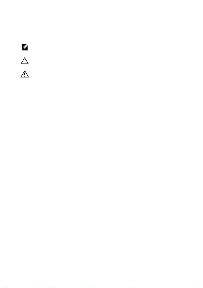
Press and hold the rail release button to open the latch on the front
end of the left rail.
Align the three pegs with the mounting holes on the front rack post.
Release the button when it engages to the front rack post.
NOTE:
Make sure the rail release button is engaged correctly.
NOTE:
The rails can be used in both square-hole and round-hole racks.
4
Getting Started With Your System
Page 7

e
2
1
3
1
2
3
Press and hold the rail release button to open the latch on the back
end of the rail.
f
Align the three pegs with the mounting holes on the back rack post.
g
Release the button when it engages to the back rack post.
Getting Started With Your System
5
Page 8
h
1
2
1
2
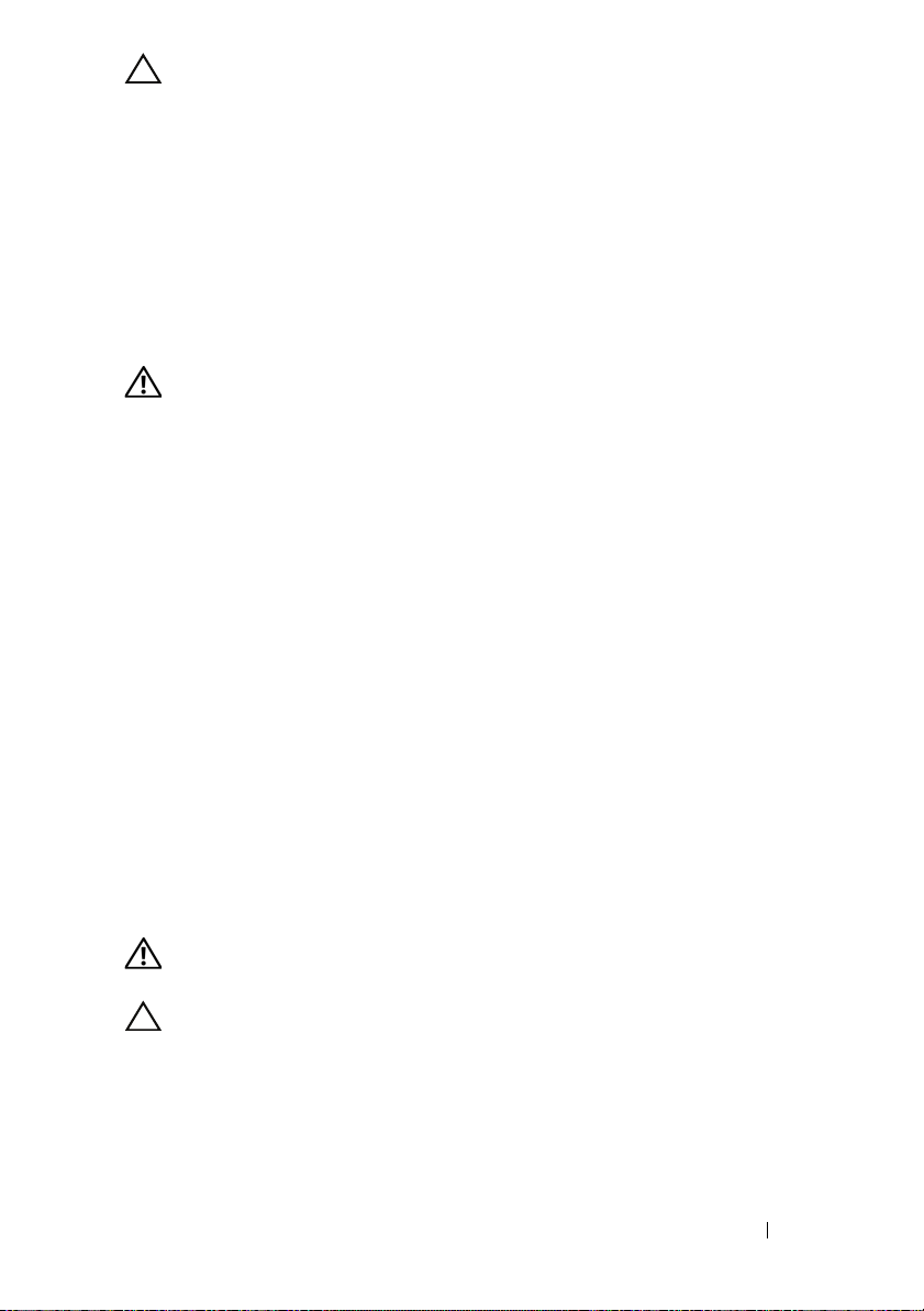
Install one cage nut to the front rack post and two cage nuts to
the back rack post.
i
Align the stopping bracket to the back rack post and secure with the
three 10-32 screws
. Apply 35 in-lbs of torque to the screws.
6
Getting Started With Your System
Page 9

4
1
2
Attach the right rail and stopping bracket to the rack.
Use the same procedure to install the right rail and stopping bracket to the
right rack posts.
NOTE:
To remove the rails, press and hold on the rail release button on the end
piece midpoint and unseat each rail.
Installing the System
This section includes the following subsections:
• Emptying the System
• Install the System Into the Rack
• Sled Bay Numbering
• Populating the System
• Install the External PDU Into the Rack
• Rack Configuration
Emptying the System
Before you install a PowerEdge C8000 server enclosure into a rack, remove all
sled modules from the enclosure to reduce system weight and avoid injury.
Place all sled modules on an antistatic mat or antistatic foam.
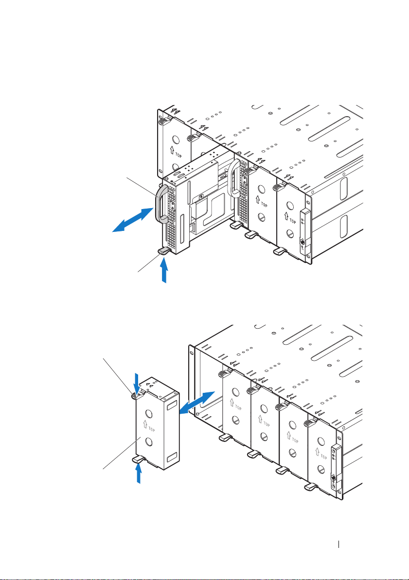
• To remove a
and using the handle slide the sled out of the enclosure.
C8220 single-wide compute sled, pull up on the
release latch
Getting Started With Your System
7
Page 10

• To remove a
2
1
1
2
latch
and using the handle slide the sled out of the enclosure.
C8220X double-wide compute sled, pull up on the
release
• To remove a
using the handle
8
Getting Started With Your System
C8000XD storage sled, pull and hold the
slide the sled out of the enclosure.
release tab and
Page 11
• To remove a power sled, pull up on the release latch and using the
1
2
1
2
handle
slide the sled out of the enclosure.
• To remove a double-wide sled blank, squeeze and hold the release latches
and pull the sled blank out of the enclosure .
Getting Started With Your System
9
Page 12

• To remove a single-wide sled blank, pull up on the release latch and
2
1
using the handle
slide the blank out of the enclosure.
10
Getting Started With Your System
Page 13

Install the System Into the Rack
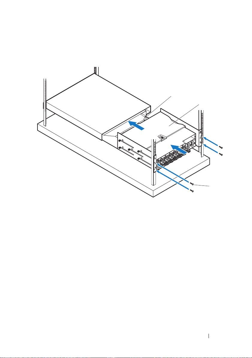
1
2
WARNING:
avoid injury, do not attempt to lift the system by yourself.
1
With assistance, align the server enclosure with the rails and push it
fully into the rack.
Whenever you need to lift the system, get others to assist you. To
Getting Started With Your System
11
Page 14

2
1
Secure the front of the enclosure to the left and right rack posts with the
four 10-32 screws
.
12
Getting Started With Your System
Page 15

Sled Bay Numbering
The PowerEdge C8000 server enclosure is divided into ten vertical bays. A
C8220 single-wide compute sled occupies one sled bay in the server enclosure
and a C8220X double-wide compute sled or C8000XD storage sled occupies
two sled bays in the server enclosure. When installing a sled module into the
server enclosure, you should install the sled module in sled bay 1 first, then
work toward the right of the enclosure.
Sled Bays
Sled module type
C8220 single-wide
12345
√√√√√√√√√√
compute sled
C8220X double-wide
√√√√√
compute sled
C8000XD storage
b
sled
Power sled
a. Sled bays 5 and 6 support installation of two power sleds or two C8220 compute sleds or a
combination of the two sled types.
b. For server enclosure with internal power source, install C8000XD storage sleds in sled bays 3 to 10
only.
c. Install power sleds in sled bays 5 and 6 only.
c
√√√√√
⎯⎯⎯⎯
a6a
√
√
78910
⎯
⎯
⎯
⎯
Getting Started With Your System
13
Page 16

Populating the System
CAUTION:
be populated at all times with either a sled or with a sled blank.
CAUTION:
have hard-drive blanks installed.
Install all components into the PowerEdge C8000 server enclosure.
• To install a
enclosure until the sled is fully seated and the release latch snaps into
place.
• To install a
the enclosure until the sled is fully seated and the release latch snaps
into place.
• To install a
until the sled is fully seated and the release tab snaps into place.
• To install a power sled, slide the new sled into the enclosure until the sled
is fully seated and the release latch snaps into place.
• To install a double-wide sled blank, slide the blank into the enclosure until
it is fully seated and the release latches snap into place.
• To install a single-wide sled blank, slide the blank into the enclosure until
it is fully seated and the release latch snaps into place.
To ensure proper operation and cooling, all bays in the enclosure must
To maintain proper system cooling, all empty hard-drive slots must
C8220 single-wide
compute sled, slide the new sled into the
C8220X double-wide compute sled, slide the new sled into
C8000XD storage sled, slide the new sled into the enclosure
14
Getting Started With Your System
Page 17

Install the External PDU Into the Rack
OFFOFFOFF
WARNING:
avoid injury, do not attempt to lift the system by yourself.
NOTE:
device documentation for more information about the PDU device.
NOTE:
attaches to the left of the PDU device and the rail marked "R" attaches to the right of
the PDU device.
WARNING:
the PDU is energized.
WARNING:
fatal electric shock.
1
Turn off the PDU breaker switches by moving the A, B, and C breaker
switches to the "OFF" position.
Whenever you need to lift the system, get others to assist you. To
The PDU device illustrations are provided as reference only. See PDU
The PDU mounting brackets are marked L and R. The rail marked "L"
Do not connect or disconnect power cables to the PDU device while
Turn off the PDU breaker switches to avoid potentially serious or
2
Disconnect the PDU from the power source.
Getting Started With Your System
15
Page 18
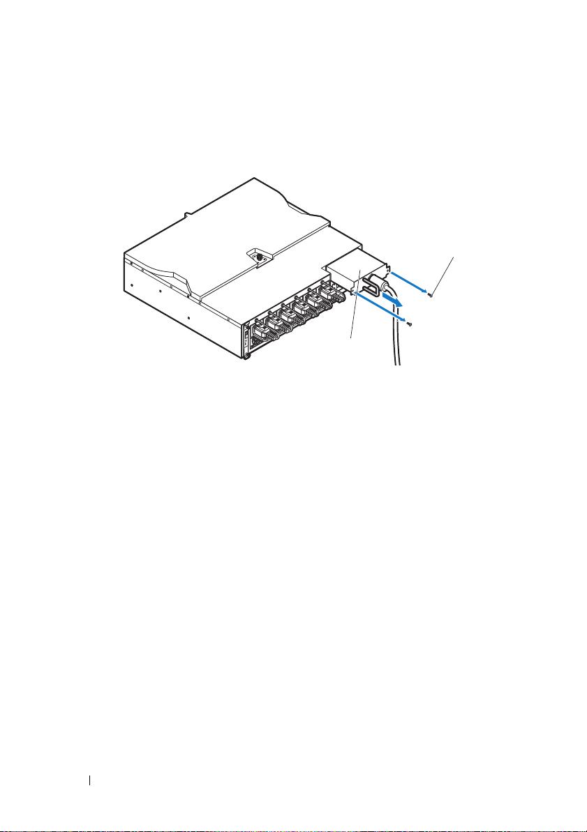
3
2
1
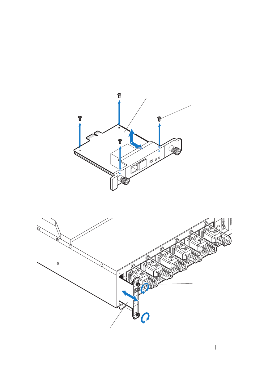
Remove the power cable interface box (PCIB) module.
a
Remove the two screws securing the PCIB module.
b
Grasp the PCIB handle and pull it out of it’s bay .
4
Attach the mounting brackets to the sides of the PDU.
a
Affix the ten screws to the left and right sides of the PDU.
b
Position the left mounting bracket marked "L" to align the screw holes
with the screws on the PDU and slide the mounting bracket toward
the back of the PDU until it locks into place
c
Position the right mounting bracket marked "R" to align the screw
holes with the screws on the PDU and slide the mounting bracket
toward the back of the PDU until it locks into place
.
.
16
Getting Started With Your System
Page 19

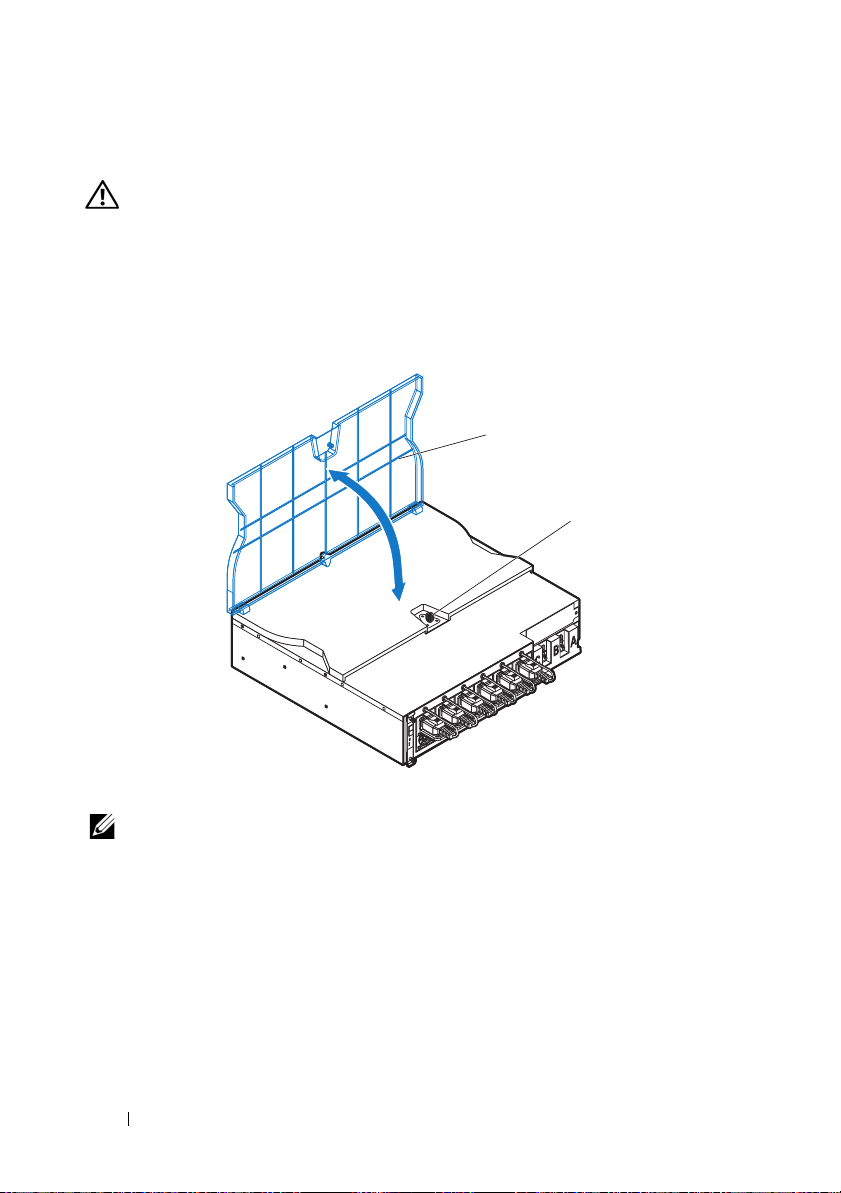
5
1
2
Install the snorkel to the PDU.
a
Remove the air duct from the snorkel.
b
Align the air duct with the front of the PDU.
c
Secure the air duct to the front of the PDU with the two screws .
Getting Started With Your System
17
Page 20

d
2
1
FRONT
1
Align the snorkel with the rack posts.
e
Secure the snorkel to the rack posts with the four screws .
18
Getting Started With Your System
Page 21
6
FRONT
1
3
2
With assistance, slide the air duct into the snorkel and secure the back
of the PDU
to the rack posts with four screws .
Getting Started With Your System
19
Page 22
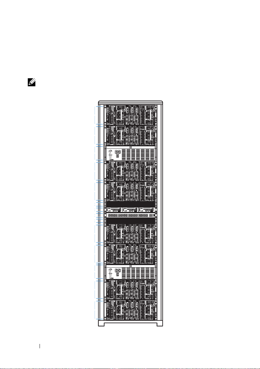
Rack Configuration
4U
4U
3U
4U
4U
4U
4U
3U
4U
4U
1U
1U
1U
1U
The following illustration shows a sample rack configuration with PowerEdge
C8000 server enclosures, power distribution unit (PDU) devices, switch and
router in a 42U rack.
NOTE:
The rack configuration illustration is provided as reference only.
20
Getting Started With Your System
Page 23
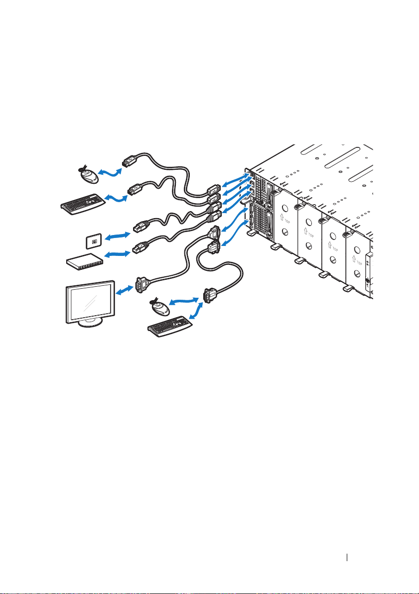
Connecting the Keyboard, Mouse, and Monitor
Connect a keyboard, mouse, and monitor to the compute sled (optional).
The following figure shows a sample keyboard, mouse, and monitor
connection to a C8220X double-wide compute sled.
Getting Started With Your System
21
Page 24

Connecting the Power Cables
2
1
This section includes instructions on how to connect the server enclosure
with internal or external power source to an external PDU.
Server Enclosure with Internal Power Source
1
On the back of the enclosure, connect the power cables to the AC power
sockets
.
2
Plug the other end of the power cables into a grounded electrical outlet or
a separate power source such as an uninterrupted power supply or the
PDU.
22
Getting Started With Your System
Page 25

Server Enclosure with External Power Source
1
3
2
WARNING:
connections.
1
On the back of the enclosure, connect the power cable to the DC power
socket
2
Tighten the two center screws on the cable to secure the connection.
Make sure power is turned off on all devices before making
.
Getting Started With Your System
23
Page 26
Connecting the Server Enclosure to a Rack PDU
2
1
WARNING:
the PDU is energized. Turn off the PDU breaker switches to avoid potentially
serious or fatal electrical shock. Move the PDU A, B, and C breaker switches to
the "OFF" position.
1
Unlock the cable cover .
2
Rotate the cover back and away from the PDU.
Do not connect or disconnect power cables to the PDU device while
3
Attach the server enclosure(s) power cables to the PDU power bus bar.
NOTE:
The PDU device supports a maximum of five PowerEdge C8000 server
enclosures depending on the system configuration and power budget.
To connect a single server enclosure to the PDU:
a
24
Secure the three black power cable lugs to the top power bus bar
(GND) with the three screws
b
Secure the three yellow power cable lugs to the bottom power bus
bar with the three screws
Getting Started With Your System
.
.
Page 27

To connect multiple server enclosures to the PDU:
3
2
1
a
Secure the first server enclosure’s three black power cable lugs to
.
.
.
the top power bus bar (GND) with the three screws
b
Secure the first server enclosure’s three yellow power cable lugs to
the bottom power bus bar with the three screws
c
Secure the second server enclosure’s three black power cable lugs to
the top power bus bar (GND) with the three screws
d
Secure the second server enclosure’s three yellow power cable lugs
to the bottom power bus bar with the three screws .
Getting Started With Your System
25
Page 28

5
4
2
3
1
NOTE:
Ensure that all power cords are connected properly and securely to the
PDU power bus bars.
4
Close the cable cover and secure to the PDU.
26
Getting Started With Your System
Page 29
Connecting the PDU to the Network
1
2
1
2
1
Install the power management controller (PMC) into the PDU and
connect to your network.
a
Secure the PMC board to the PMC tray with the four screws .
b
Insert the PMC assembly to the PDU and secure with the two
thumbscrews
.
Getting Started With Your System
27
Page 30

c
2
1
Connect the network cable to the NIC port 1 .
28
Getting Started With Your System
Page 31

Powering Up the Systems
1
2
Turning on the PDU
1
Install the PCIB module into the PDU.
a
Insert the PCIB module into the PCIB bay .
b
Secure the PCIB module to the PDU with the two screws .
2
Connect the PDU to the power source.
Getting Started With Your System
29
Page 32

3
ONONON
Turn on the PDU breaker switches by moving the A, B, and C breaker
switches to the "ON" position.
4
To enable monitoring of the PDU device over the network, turn on the
PMC board by pressing the power button, located on the PMC board.
When power is applied to the PDU, the power/status indicator on the
front of the PMC board will light up green.
NOTE:
The PMC board and PDU device illustrations in this guide are provided as
reference only. See PDU device documentation for more information about the PMC
board and PDU device.
Turning On the Server Enclosure
When connected to a power source, main power is automatically distributed
to the server enclosure. After the server enclosure is powered up the
power/event indicator on the front of the enclosure will light up green and
main power is applied to all sleds in the enclosure.
30
Getting Started With Your System
Page 33

Turning On the Sleds
To turn on the C8220 or C8220X compute sled, press the power button on
each sled, or power on the sled using the baseboard management controller.
When power is applied to the sled, the power-on indicator on front of the sled
will light up green. When installed into the server enclosure, the C8000XD
storage sled automatically powers on. See Using the Baseboard Management
Controller Guide at dell.com/support/manuals.
Getting Started With Your System
31
Page 34

Complete the Operating System Setup
To install an operating system for the first time, see the installation and
configuration documentation for your operating system. Be sure the
operating system is installed before installing hardware or software not
purchased with the system.
Supported Operating Systems
• Citrix XenServer Enterprise Edition 5.6
• Citrix XenServer Enterprise Edition 6.1
• Microsoft Windows Server 2008 Enterprise Edition Release 2 (64-bit)
• Microsoft Windows Server 2012
• Microsoft Windows HPC 2008 Release 2
• Microsoft HyperV
• Red Hat Enterprise Linux 6.1 (64-bit)
• Red Hat Enterprise Linux 6.3 (64-bit)
• SUSE Linux Enterprise Server 11 SP2 (64-bit)
• Ubuntu 12.04.1 LTS 64-bit
• VMware ESXi 5.0
• VMware ESXi 5.0 U1
• VMware ESXi 5.0 U2
• VMware ESX 5.1
• VMware ESXi 5.1 U1
NOTE:
dell.com/ossupport.
32
For the latest information on supported operating systems, see
Getting Started With Your System
Page 35

Other Information You May Need
WARNING:
system. Warranty information may be included within this document or as a
separate document.
• The PowerEdge C8000 Hardware Owner’s Manual for information about
the server enclosure features, troubleshooting, and component
replacement. This document is available at
• The PowerEdge C8220 Hardware Owner’s Manual for information about
system features, troubleshooting, and component replacement. This
document is available at
• The PowerEdge C8220X Hardware Owner’s Manual for information about
system features, troubleshooting, and component replacement. This
document is available at
• The PowerEdge C8000XD Hardware Owner’s Manual for information
about system features, troubleshooting, and component replacement. This
document is available at
• The Baseboard Management Controller Guide provides information about
installing and using the systems management utility. This document is
available at
NOTE:
supersede information in other documents.
See the safety and regulatory information that shipped with your
dell.com/support/manuals
dell.com/support/manuals
dell.com/support/manuals
dell.com/support/manuals
dell.com/support/manuals
Always check for updates and read the updates first because they often
.
.
.
.
.
Getting Started With Your System
33
Page 36

NOM Information
PowerEdge C8000
The following information is provided on the device described in this
document in compliance with the requirements of the official Mexican
standards (NOM):
Importer: Dell Inc. de México, S.A. de C.V.
Paseo de la Reforma 2620-11° Piso
Col. Lomas Altas
11950 México, D.F.
Model number: B10S
Supply voltage: 200–240 V CA (with four 1400 W AC Power Supply Unit) or
12 V DC (with external PDU)
Frequency: 50–60 Hz
Current consumption: 9 A (x4) (with four 1400 W AC Power Supply Unit) or
480 A (with external PDU)
PowerEdge C8220
The following information is provided on the device described in this
document in compliance with the requirements of the official Mexican
standards (NOM):
Importer: Dell Inc. de México, S.A. de C.V.
Paseo de la Reforma 2620-11° Piso
Col. Lomas Altas
11950 México, D.F.
Model number: B05B
Supply voltage: 12 V DC
Current consumption: 42 A
34
Getting Started With Your System
Page 37

PowerEdge C8220X
The following information is provided on the device described in this
document in compliance with the requirements of the official Mexican
standards (NOM):
Importer: Dell Inc. de México, S.A. de C.V.
Paseo de la Reforma 2620-11° Piso
Col. Lomas Altas
11950 México, D.F.
Model number: B06B
Supply voltage: 12 V DC
Current consumption: 92 A
PowerEdge C8000XD
The following information is provided on the device described in this
document in compliance with the requirements of the official Mexican
standards (NOM):
Importer: Dell Inc. de México, S.A. de C.V.
Paseo de la Reforma 2620-11° Piso
Col. Lomas Altas
11950 México, D.F.
Model number: B06B
Supply voltage: 12 V DC
Current consumption: 30 A
Getting Started With Your System
35
Page 38

Technical Specifications
Compute Sled Specifications (Per Sled)
Processor
Processor type Two Intel Xeon E5 series processors
Processor socket Two LGA 2011
System chipset
Platform Controller Hub Intel X79
Network Controller Intel i350-BT2
Video Controller Aspeed AST2300
Memory
Memory type DDR3 UDIMM, RDIMM, LRDIMM
Memory module sockets 16 DIMM sockets
Memory module capacities 2 GB, 4 GB, 8 GB, 16 GB, and 32 GB
RDIMMs
Minimum RAM 512 MB UDIMM; 1 GB RDIMM
Maximum RAM 128 GB UDIMMs; 256 GB RDIMMs
No. of memory channels (Per CPU) 4 channels
Storage device
PowerEdge C8220 single-wide
compute sled
PowerEdge C8220X double-wide
compute sled
• 3 Gb/s SATA port x 4
• 6 Gb/s SATA port x 2
• 2.5-inch SATA HDDs x2
• 3 Gb/s SATA port x 4
• 6 Gb/s SATA port x 2
• 2.5-inch SATA HDDs x 2
• 2.5-inch SAS/SATA HDDs x 8 or
3.5-inch SAS/SATA HDDs x 4
• 2.5-inch hot-plug SAS/SATA HDDs x 2
(PowerEdge C8220X with front-access
2.5-inch hot-plug hard drives)
36
Getting Started With Your System
Page 39

Compute Sled Specifications (Per Sled)(continued)
Graphics card
PowerEdge C8220X double-wide
compute sled
Expansion slots
PowerEdge C8220 single-wide
compute sled
PowerEdge C8220X double-wide
compute sled
PowerEdge C8220X with
GPGPU/MIC double-wide
compute sled
Interfaces
BMC management port 1 front
NIC Two 1Gb NIC ports
Serial 1 front
VGA 1 front
USB 2 front
UID LED 1 front
Power
Batteries
System battery
RAID battery (optional)
PowerEdge C8220X with GPGPU/MIC
• NVIDIA Tesla M2090
• NVIDIA Tesla K20
• Intel Xeon Phi 5110P
• One x16 PCI Express 2.0 slot
• One x8 mezzanine slot
• Two x8 PCI Express 3.0 slot (x16 connector
type)
• One x8 mezzanine slot
• One x16 PCI Express 3.0 slot via single riser
• One x16 PCI Express 3.0 slot via cable
• One x8 mezzanine slot
CR 2032 3.0-V lithium ion coin cell
3.7 V lithium ion battery pack
Getting Started With Your System
37
Page 40

Storage Sled Specifications (Per Sled)
HDD Sled Configuration
Dual port mode (redundant) Standard carrier
Single port mode (non-redundant)
Expansion mode (non-zoning/
two zone/four zone)
Storage device
Standard carrier 3.5-inch SAS/SATA/SSD HDD x 12
Flexible carrier 2.5-inch SAS/SATA/SSD HDD x 12
Expansion carrier 2.5-inch SSD HDD x 24
Interface
Mini-SAS 4 front
Power Sled Specifications (Per Sled)
Interfaces
Power LED 2 front
Power connector 2 DC connector (12 V & GND)
Power supply module (per power supply)
Wattage 1400 W
Connector IEC C20
Voltage 200–240 V AC, 50–60 Hz, 9 A max
Heat dissipation 1205 BTU/hr. maximum
Maximum inrush current Under typical line conditions and over the
• Standard carrier
• Flexible carrier
• Expansion carrier
Expansion carrier
entire system ambient operating range, the
inrush current may reach 25 A per power
supply for 10 ms or less
38
Getting Started With Your System
Page 41

Server Enclosure Specifications
Physical
Height 17.5 cm (6.9 in.)
Width 44.7 cm (17.6 in.)
Depth 81.3 cm (32.0 in.)
Weight (empty) 17.93 kg (39.53 lbs.)
Sled Support
Server enclosure with internal
power source
Server enclosure with external
PDU
Interfaces
NIC Two 10/100Mbit NIC ports (1 front, 1 back)
Serial 1 back
Power/event LED 2 (1 front, 1 back)
UID LED 2 (1 front, 1 back)
Ethernet activity LED 1 front
Thermal sensor 1 front
System fan module failure LED 3 back
System fans
Fan type 3 fan modules (2 fans per module/6 total)
Power
DC power supply
Vo lt ag e
with external PDU
• Up to 8 C8220 single-wide compute sleds
• Up to 4 C8220X double-wide compute sleds
• Up to 4 C8000XD storage sleds
• Up to 2 power sleds
• Up to 10 C8220 single-wide compute sleds
• Up to 5 C8220X double-wide compute sleds
• Up to 5 C8000XD storage sleds
12 V DC, 50–60 Hz, 680 A max with 6 PSU
populated
Getting Started With Your System
39
Page 42

Environmental
NOTE:
For additional information about environmental measurements for specific
system configurations, see the dell.com/environmental_datasheets.
Te mp e ra t u re
Operating
Storage
Relative Humidity
Operating
Storage
Maximum vibration
Operating
Storage
Maximum shock
Operating
Storage
10 °C to 35 °C (50 °F to 95 °F) with a maximum
temperature gradation of 10 °C per hour
–40 °C to 65 °C (40 °F to 149 °F) with a
maximum temperature gradation of 20 °C per
hour
20% to 80% (noncondensing) with a maximum
humidity gradation of 10% per hour
5% to 95% (noncondensing)
0.26 Grms at 5–350 Hz
1.87 Grms at 10–500 Hz for 15 min
One shock pulse in the positive z axis (one pulse
on each side of the system) of 31 G for 2.6 ms in
the operational orientation
Six consecutively executed shock pulses in the
positive and negative x, y, and z axes (one pulse
on each side of the system) of 71 G for up to
2 ms;
Six consecutively executed shock pulses in the
positive and negative x, y, and z axes (one pulse
on each side of the system) of 27 G faired square
wave pulse with velocity change at 235
inches/second (597 centimeters/second)
40
Getting Started With Your System
Page 43

Environmental(continued)
Altitude
Operating
Storage
Airborne Contaminant Level
Class
-16 to 3,048 m (-50 to 10,000 ft.)
NOTE:
For altitudes above 2,950 feet, the maximum
operating temperature is derated to 1°F/550 ft.
-16 to 10, 600 m (-50 to 35,000 ft.)
G1 as defined by ISA-S71.04-1985
Getting Started With Your System
41
Page 44

42
Getting Started With Your System
Page 45

Dell PowerEdge
C8000, C8220, C8220X,
et C8000XD
Mise en route
de votre système
EMPLACEMENT DU FICHIER : J:\DL\DL133448\DTP\P06HNft4.fm
Modèle réglementaire : B10S, B05B
et B06B
Type réglementaire : B10S001, B05B001,
B06B001 et B06B002
Page 46

EMPLACEMENT DU FICHIER : J:\DL\DL133448\DTP\P06HNft4.fm
Remarques, précautions et avertissements
REMARQUE :
vous aider à mieux utiliser votre ordinateur.
PRÉCAUTION :
perte de données en cas de non-respect des instructions.
AVERTISSEMENT:
d'endommagement du matériel, de blessure corporelle ou même de mort.
____________________
Les informations que contient cette publication sont sujettes à modification sans préavis.
© 2013 Dell Inc. Tous droits réservés.
La reproduction de ce document de quelque manière que ce soit sans l'autorisation écrite de Dell Inc.
est strictement interdite.
Marques utilisées dans ce document : Dell™, le logo DELL, Dell Precision™, OptiPlex™, Latitude™,
PowerEdge™, PowerVault™, PowerConnect™, OpenManage™, EqualLogic™, KACE™,
FlexAddress™ et V ostro™ sont des marques de Dell Inc. Intel
et Xeon Phi™ sont des marques déposées d'Intel Corporation aux États-Unis et dans d'autres pays.
Microsoft
marques déposées de Microsoft Corporation aux États-Unis et/ou dans d'autres pays. Red Hat
Red Hat
d'autres pays. Novell
États-Unis et/ou dans d'autres pays. Oracle
ses filiales. Citrix
de Citrix Systems, Inc. aux États-Unis et/ou dans d'autres pays. VMware
vCenter
et/ou dans d'autres pays. NVIDIA et Tesla™ sont des marques et/ou des marques déposées de
NVIDIA Corporation. Ubuntu est une marque déposée de Canonical Ltd.
D'autres marques et noms commerciaux peuvent être utilisés dans cette publication pour faire référence
aux entités revendiquant la propriété de ces marques ou noms ou à leurs produits. Dell Inc. rejette tout
intérêt exclusif dans les marques et les noms commerciaux autres que les siens.
®
, Windows®, Windows Server®, MS-DOS® et Windows V ista® sont des marques ou des
®
Enterprise Linux® sont des marques déposées de Red Hat, Inc. aux États-Unis et/ou dans
®
et vSphere® sont des marques déposées ou des marques de VMWare, Inc. aux États-Unis
Une REMARQUE indique des informations importantes qui peuvent
Une PRÉCAUTION indique un risque de dommage matériel ou de
Un AVERTISSEMENT vous avertit d’un risque
®
, Pentium®, Xeon®, Core™, Celeron®
®
®
est une marque déposée et SUSE™ est une marque de Novell Inc. aux
®
, Xen®, XenServer® et XenMotion® sont des marques ou des marques déposées
®
est une marque déposée d'Oracle Corporation et/ou de
®
, Virtual SMP®, vMotion®,
et
Modèle réglementaire : B10S, B05B et B06B
Type réglementaire : B10S001, B05B001, B06B001 et B06B002
2013 - 07 P/N P06HN Rév. A04
Page 47

PRÉCAUTION :
Ce serveur est conçu pour être installé uniquement dans des lieux à accès
restreint où les deux conditions suivantes s'appliquent :
• Seuls peuvent avoir accès le personnel d'entretien et les utilisateurs
qui ont été informés des motifs des restrictions appliquées au lieu et
des précautions à prendre.
• L'accès, qui se fait par l'intermédiaire d'un outil ou d'un verrou et
d'une clé, ou par d'autres moyens de sécurité, est contrôlé par le
responsable en charge du lieu.
Lieux à accès restreint
Installation et configuration
AVERTISSEMENT :
consignes de sécurité fournies avec le système et veillez à les respecter.
Le châssis du serveur PowerEdge C8000 est un châssis 4U monté en rack,
flexible et évolutif. Le serveur PowerEdge C8000 comporte dix baies de
plateaux alignées verticalement prenant en charge un châssis de chariot
complet ou mixte. Un boîtier de chariot complet peut contenir jusqu'à cinq
plateaux de calcul C8220X double largeur, dix plateaux de calcul C8220
simple largeur ou cinq plateaux de stockage C8000XD. Un boîtier de chariots
mixte peut contenir une combinaison de différents types de chariots.
Outils recommandés
Avant de commencer les tâches d'installation, vérifiez que vous possédez les
éléments suivants :
• Tournevis cruciforme n°1
• Tournevis cruciforme n° 2
• Bracelet de mise à la terre connecté au sol
• Tapis antistatique ou carton mousse antistatique
Avant de commencer la procédure suivante, lisez les
Déballage du système
AVERTISSEMENT :
N'essayez pas de le soulever seul, car vous risqueriez de vous blesser.
PRÉCAUTION :
composants du système.
Demandez toujours de l'aide avant de soulever le système.
Portez le bracelet de mise à terre lors de la manipulation de
Mise en route de votre système
45
Page 48

1
Préparez
un tapis antistatique ou une mousse antistatique
pour activer le
boîtier du serveur PowerEdge C8000.
2
Déballez et placez votre boîtier sur
antistatique
3
Conservez les cartons d'emballage pour un usage ultérieur.
.
un tapis antistatique ou une mousse
Installation sans outil des rails
AVERTISSEMENT:
N'essayez pas de le soulever seul, car vous risqueriez de vous blesser.
AVERTISSEMENT:
soutenir correctement au cours de l'installation et du retrait pour éviter de
l'endommager ou de vous blesser.
AVERTISSEMENT:
disposer d'un troisième conducteur de mise à la terre pour l'installation du rack.
L'équipement du rack doit assurer un flux d'air suffisant pour bien refroidir
le système.
PRÉCAUTION :
rack pour une installation correcte.
REMARQUE :
Le rail marqué « LEFT » se fixe sur les montants de rack de gauche et celui marqué
« RIGHT » se fixe sur les montants de rack de droite, lorsque vous faites face à
l'avant du rack.
1
Déterminez où placer les rails dans le rack. Assurez-vous de ménager un
espace suffisant dans le rack pour un châssis 4U. Dans un rack standard,
la hauteur d'un châssis 4U s'étend sur 12 trous de montant.
2
Utiliser le marquage indiqué sur les côtés gauche et droit du rail pour
orienter correctement les rails par rapport aux montants du rack.
3
Fixez le rail gauche et le support d'arrêt sur le rack.
a
Positionnez le rail de gauche marqué «
orifices de montage sur les montants du rack.
b
Appuyez sur le bouton d'éjection du rail et maintenez-le enfoncé
pour ouvrir le loquet à l'avant du rail.
c
Alignez les trois chevilles avec les orifices de montage situés sur le
montant de rack avant.
d
Relâchez le bouton lorsqu'il s'engage au montant du rail avant.
REMARQUE :
Demandez toujours de l'aide avant de soulever le système.
Le système n'est fixé ni au rack ni aux rails. Vous devez le
Afin d'éviter un éventuel choc électrique, assurez-vous de
Les chevilles de rail doivent être alignés avec les montants de
Les rails pour rack sont marqués LEFT (Gauche) et RIGHT (Droite).
LEFT
» pour l'aligner avec ses
Assurez-vous que le bouton d'éjection du rail est bien enfoncé.
46
REMARQUE :
et à trous ronds.
Mise en route de votre système
Les rails peuvent être utilisés à la fois dans des racks à trous carrés
Page 49

e
2
1
3
1
2
3
Appuyez sur le bouton d'activation du rail et maintenez-le enfoncé
pour ouvrir le loquet à l'arrière du rail.
f
Alignez les trois chevilles avec les orifices de montage situés sur le
montant de rack arrière.
g
Relâchez le bouton lorsqu'il s'engage au montant du rail arrière.
Mise en route de votre système
47
Page 50

h
1
2
1
2
Installez un écrou à cage au montant du rail avant et deux écrous à
cage
au montant de rail arrière.
i
Alignez le support d'arrêt au montant arrière du châssis et fixez-le
à l'aide de trois vis 10-32
. Appliquez 35 lb-po de couple de serrage
aux vis.
48
Mise en route de votre système
Page 51

4
1
2
Fixez le rail de droite et le support d'arrêt sur le rack.
Utilisez la même procédure pour installer le rail de droite et le support
d'arrêt sur les montants droits rack.
REMARQUE :
rail situé au milieu de l'extrémité et dégagez les rails un par un.
Pour retirer les rails, appuyez et maintenez le bouton d'éjection du
Installation du système
Cette section inclut les sous-sections suivantes :
• Vidage du système
• Installer le système dans le rack
• Numérotation des baies de chariot
• Remplissage du système
• Installer les unités de distribution de l'alimentation externe dans le rack
• Configuration du rack
Vidage du système
Avant d'installer un boîtier de serveur PowerEdge C8000 dans un rack, retirez
tous les modules de chariot du boîtier pour diminuer le poids du système et
éviter des risques de blessure. Placez tous les modules de chariot sur un tapis
antistatique ou une mousse antistatique.
• Pour retirer un
de dégagement
chariot hors du boîtier.
module de chariot largeur unique C8220, tirez le
et au moyen de la poignée faites glisser le module de
loquet
Mise en route de votre système
49
Page 52

•Pour retirer un
2
1
1
2
de dégagement
chariot hors du boîtier.
module de chariot double largeur C8220X, tirez le
et au moyen de la poignée faites glisser le module de
loquet
• Pour retirer un
maintenez la
faites glisser le module de chariot hors du boîtier.
50
Mise en route de votre système
module de chariot de stockage C8000XD, tirez et
languette de dégagement puis au moyen de la poignée
Page 53

• Pour retirer un module de chariot, tirez sur le loquet de dégagement et
1
2
1
2
au moyen de la poignée
faites glisser le module de chariot hors du boîtier.
• Pour retirer un module de chariot double largeur, serrez et tenez les loquets
de dégagement
puis tirez le module de chariot hors du boîtier .
Mise en route de votre système
51
Page 54

• Pour retirer un module de chariot largeur unique, tirez le loquet de
2
1
dégagement et au moyen de la poignée
faites glisser le cache hors
du boîtier.
52
Mise en route de votre système
Page 55

Installer le système dans le rack
1
2
AVERTISSEMENT :
N'essayez pas de le soulever seul, car vous risqueriez de vous blesser.
1
En vous faisant aider, alignez le boîtier de serveur aux rails puis
poussez-le entièrement à l'intérieur du rack.
Demandez toujours de l'aide avant de soulever le système.
Mise en route de votre système
53
Page 56

2
1
Fixez l'avant du boîtier aux montants gauche et droit du rack à l'aide de
quatre vis 10-32
.
54
Mise en route de votre système
Page 57

Numérotation des baies de chariot
Le châssis du serveur PowerEdge C8000 se divise en dix baies verticales.
Un chariot de calcul largeur unique C8220 occupe une baie de chariot dans
le boîtier du serveur et un chariot de calcul double largeur C8220X ou un
chariot de stockage C8000XD occupe deux baies de chariot dans le boîtier
du serveur. Lorsque vous installez un module de chariot dans le boîtier du
serveur, vous devez commencer par la baie de chariot 1, puis vous déplacer
vers la droite du châssis.
Baies de chariot
Type de module de
chariot
Chariot de calcul
12345
√√√√√√√√√√
largeur unique C8220
Chariot de calcul
√√√√√
double largeur C8220X
stockage C8000XD
b
chariot
Chariot d'alimentation
a. Les baies 5 et 6 prennent en charge l'installation d'un maximum de deux chariots d'alimentation ou
de deux chariots de calcul C8220 ou une combinaison des deux types de chariots.
b. Dans le cas des enceintes de serveur avec source d'alimentation interne, installez les chariots de
stockage C8000XD dans les baies de chariot 3 à 10 uniquement.
c. Les chariots d'alimentation s'installent uniquement dans les baies de chariot 5 et 6.
√√√√√
c
⎯⎯⎯⎯
a6a
√
√
78910
⎯
⎯
⎯
⎯
Mise en route de votre système
55
Page 58

Remplissage du système
PRÉCAUTION :
toutes les baies du boîtier doivent constamment être occupées par un chariot ou
un chariot factice.
PRÉCAUTION :
installer un cache dans tous les logements de disque dur vacants.
Installez tous les composants dans le boîtier de serveur PowerEdge C8000.
• Pour installer un plateau de calcul
dans le châssis jusqu'à ce qu'il soit en place et que le loquet de dégagement
s'enclenche.
• Pour installer un
glisser dans le châssis jusqu'à ce qu'il soit en place et que le loquet de
dégagement s'enclenche.
• Pour installer un
glisser dans le châssis jusqu'à ce qu'il soit en place et que la languette de
dégagement s'enclenche.
• Pour installer un plateau d'alimentation, faites-le glisser dans le châssis
jusqu'à ce qu'il soit en place et que le loquet de dégagement s'enclenche.
• Pour installer un cache de chariot double largeur, faites-le glisser dans
le châssis jusqu'à ce qu'il soit en place et que le loquet de dégagement
s'enclenche.
• Pour installer un cache de chariot largeur unique, faites-le glisser dans
le châssis jusqu'à ce qu'il soit en place et que le loquet de dégagement
s'enclenche.
Pour assurer un fonctionnement et un refroidissement corrects,
Pour assurer un refroidissement correct du système, vous devez
C8220 à largeur simple
, faites-le glisser
plateau de calcul C8220X à largeur double, faites-le
plateau de stockage C8000XD à largeur double, faites-le
56
Mise en route de votre système
Page 59

Installer les unités de distribution de l'alimentation externe dans le rack
OFFOFFOFF
AVERTISSEMENT :
N'essayez pas de le soulever seul, car vous risqueriez de vous blesser.
REMARQUE :
référence uniquement. Reportez-vous à la documentation du périphérique PDU
pour plus d'informations sur celui-ci.
REMARQUE :
sont marqués L et R. Le rail marqué « L » s'attache à la gauche de l'unité de
distribution de l'alimentation des périphériques et celui marqué « R » s'attache à la
droite de l'unité de distribution de l'alimentation.
AVERTISSEMENT :
PDU pendant que l'unité de distribution de l'alimentation est sous tension et ne
les déconnectez pas non plus dans ce cas.
AVERTISSEMENT :
électrique potentiellement fatal.
1 Éteignez l'unité de distribution de l'alimentation en plaçant les
commutateurs A, B et C à la position « OFF ».
Demandez toujours de l'aide avant de soulever le système.
Les illustrations du périphérique PDU sont fournies à titre de
Les supports de montage des unités de distribution de l'alimentation
Ne connectez pas les câbles d'alimentation au périphérique
Éteignez le module PDU pour éviter tout risque de choc
Déconnectez l'unité de distribution de l'alimentation de la source
2
d'alimentation électrique.
Mise en route de votre système
57
Page 60

3
2
1
Retirez le module PCIB (boîte d'interface de câble d'alimentation).
a
Retirez les deux vis de fixation du module PCIB.
b
Saisissez la poignée du module PCIB et tirez-le hors de sa baie .
4
Fixez les supports de montage aux côtés de l'unité de distribution de
l'alimentation.
a
Apposer les dix vis sur les côtés gauche et droit du module PDU.
b
Positionnez le support de montage gauche marqué « L » pour aligner
les trous de vis avec les vis de l'unité de distribution de l'alimentation
et faites glisser la bride de fixation vers l'arrière de l'unité de
distribution de l'alimentation jusqu'à ce qu'elle se verrouille
c
Positionnez le support de montage droit marqué « R » pour aligner les
trous de vis avec les vis de l'unité de distribution de l'alimentation et
faites glisser la bride de fixation vers l'arrière de l'unité de distribution
de l'alimentation jusqu'à ce qu'elle se verrouille
.
.
58
Mise en route de votre système
Page 61

5
1
2
Installez le snorkel sur l'unité de distribution de l'alimentation.
a
Retirez le conduit d'air du snorkel.
b
Alignez le conduit d'air avec l'avant de l'unité de distribution
de l'alimentation.
c
Fixez le conduit d'air à l'avant de l'unité de distribution de
l'alimentation à l'aide des deux vis
.
Mise en route de votre système
59
Page 62

d
2
1
FRONT
1
Alignez le snorkel avec les montants du rack.
e
Fixez le tube aux montants du rack à l'aide des quatre vis .
60
Mise en route de votre système
Page 63

6
FRONT
1
3
2
Avec de l'assistance, faites glisser le conduit d'air dans le tube et fixez
l'arrière de l'unité de distribution de l'alimentation
rack à l'aide de quatre vis
.
aux montants du
Mise en route de votre système
61
Page 64

Configuration du rack
4U
4U
3U
4U
4U
4U
4U
3U
4U
4U
1U
1U
1U
1U
L'illustration suivante présente un exemple de configuration de rack avec
châssis de serveur PowerEdge C8000, périphériques d'unités de distribution
de l'alimentation (PDU), commutateur et routeur dans un rack 42U.
REMARQUE :
référence uniquement.
L'illustration de la configuration de rack est fournie qu'à titre de
62
Mise en route de votre système
Page 65

Connexion du clavier, de la souris et du moniteur
Connectez un clavier, une souris et un moniteur au plateau de calcul
(facultatif).
La figure suivante illustre la connexion d'un clavier, d'une souris et d'un
moniteur à un plateau de calcul C8220X à largeur double.
Mise en route de votre système
63
Page 66

Connexion des câbles d'alimentation
2
1
Cette section explique comment connecter l'enceinte du serveur avec source
d'alimentation interne ou externe à une PDU externe.
Boîtier de serveur avec source d'alimentation interne
1
À l'arrière du boîtier, connectez les câbles d'alimentation aux prises
d'alimentation CA
.
2
Branchez ensuite l'autre extrémité des câbles d'alimentation sur une prise
de courant mise à la terre ou sur une source d'alimentation autonome,
telle qu'un bloc d'alimentation non interrompu ou la PDU).
64
Mise en route de votre système
Page 67

Boîtier de serveur avec source d'alimentation externe
1
3
2
AVERTISSEMENT :
périphériques avant d'établir les connexions.
1
À l'arrière du boîtier, connectez le câble d'alimentation à la prise
d'alimentation CC
2
Serrez les deux vis centrales sur le câble pour sécuriser la connexion.
Assurez-vous que l'alimentation est désactivée sur tous les
.
Mise en route de votre système
65
Page 68

Connexion de l'enceinte du serveur à une unité
2
1
de distribution de l'alimentation du rack
AVERTISSEMENT:
PDU pendant que l'unité de distribution de l'alimentation est sous tension et ne
les déconnectez pas non plus dans ce cas. Éteignez le module PDU pour éviter
tout risque de choc électrique potentiellement fatal. Mettez les commutateurs
du module PDU A, B et C à la position « OFF ».
1
Déverrouillez le capot des câbles .
2
Faites pivoter le capot vers l'arrière et à l'écart de l'unité de distribution
de l'alimentation.
Ne connectez pas les câbles d'alimentation au périphérique
3
Branchez les câbles d'alimentation des enceintes de serveur à la barre du
bus d'alimentation de la PDU.
REMARQUE :
emceintes de PowerEdge C8000 serveur en fonction de la configuration du système
et du budget de consommation.
Le périphérique PDU prend en charge un maximum de cinq
Pour connecter un seul châssis de serveur à l'unité de distribution de
l'alimentation :
a
Sécurisez les trois écrous de câble d'alimentation noires à la barre
.
.
66
bus du haut au moyen de trois vis
b
Sécurisez les trois écrous de câble d'alimentation jaunes à la barre
bus du bas au moyen de trois vis
Mise en route de votre système
Page 69

Pour connecter plusieurs boîtiers de serveur à l'unité de distribution de
3
2
1
l'alimentation :
a
Sécurisez les trois écrous de câble d'alimentation noires du premier
boîtier de serveur
b
Sécurisez les trois écrous de câble d'alimentation jaunes du premier
boîtier de serveur
c
Sécurisez les trois écrous de câble d'alimentation noires du premier
boîtier de serveur
d
Sécurisez les trois écrous de câble d'alimentation jaunes du second
boîtier de serveur
à la barre bus du haut au moyen de trois vis .
à la barre bus du bas au moyen de trois vis .
à la barre bus du haut au moyen de trois vis .
à la barre bus du bas au moyen de trois vis .
Mise en route de votre système
67
Page 70

5
4
2
3
1
REMARQUE :
solidement connectés aux barres du bus de l'unité de distribution de l'alimentation.
4
Fermez le couvercle de protection des câbles et fixez-le à l'unité de
Vérifiez que tous les cordons d'alimentation sont correctement et
distribution de l'alimentation.
68
Mise en route de votre système
Page 71

Connexion de la PDU au réseau
1
2
1
2
1
Installez le contrôleur de gestion de l'alimentation (PMC) dans l'unité de
distribution de l'alimentation et connectez-vous à votre réseau.
a
Fixez la carte PMC au plateau du PMC avec les quatre vis .
b
Insérez l'assemblage PMC dans l'unité de distribution de
l'alimentation et fixez-le à l'aide des deux vis moletées
.
Mise en route de votre système
69
Page 72

c
2
1
Branchez le câble réseau au port de carte réseau 1.
70
Mise en route de votre système
Page 73

Mise sous tension du système
1
2
Mise sous tension de l'unité de distribution de l'alimentation
1
Installez le module PCIB dans l'unité de distribution de l'alimentation.
a
Insérez le module PCIB dans la baie PCIB .
b
Fixez le module PCIB dans l'unité de distribution de l'alimentation à
l'aide des deux vis
.
2
Connectez l'unité de distribution de l'alimentation à la source
d'alimentation.
Mise en route de votre système
71
Page 74

3
ONONON
Allumez l'unité de distribution de l'alimentation en mettant les
commutateurs A, B et C à la position « ON ».
4
Pour activer la surveillance des unités de distribution de l'alimentation via
le réseau, allumez la carte PMC en appuyant sur le bouton d'alimentation,
situé sur la carte PMC. Lorsque l'alimentation est appliquée à l'unité de
distribution de l'alimentation, l'indicateur d'alimentation/d'état à l'avant
de la carte PMC s'allume en vert.
REMARQUE :
guide sont fournies à titre de référence uniquement. Reportez-vous à la
documentation du périphérique PDU pour plus d'informations sur celui-ci.
Les illustrations de la carte PMC et du PMC contenues dans ce
Mise sous tension du boîtier de serveur
Lorsque le système est connecté à une source d'alimentation, l'alimentation
principale est automatiquement distribuée au châssis du serveur. Une fois
le châssis du serveur alimenté, le voyant d'alimentation/événement situé à
l'avant du châssis s'allume en vert et l'alimentation principale est distribuée
à tous les plateaux du châssis.
72
Mise en route de votre système
Page 75

Mise sous tension des plateaux
Pour mettre sous tension le plateau de calcul C8220 ou C8220X, appuyez sur
le bouton d'alimentation correspondant ou utilisez le contrôleur de gestion de
la carte mère. Lorsque le chariot est sous tension, le voyant d'alimentation
situé à l'avant du chariot s'allume en vert. Lorsqu'il est installé dans le châssis
du serveur, le plateau de stockage C8000XD s'allume automatiquement.
Consultez également le Guide du contrôleur de gestion de la carte mère à
l'adresse support.dell.com/manuals.
Mise en route de votre système
73
Page 76

Finalisation de l'installation du système d'exploitation
Consultez la documentation relative à l'installation et à la configuration du
système d'exploitation si vous installez celui-ci pour la première fois. Veillez à
installer le système d'exploitation avant tout élément matériel ou logiciel
acheté séparément.
Systèmes d'exploitation pris en charge
• Citrix XenServer Enterprise Edition 5.6
• Citrix XenServer Enterprise Edition 6.1
• Microsoft Windows Server 2008 Enterprise Edition Release 2 (64 bits)
• Microsoft Windows Server 2012
• Microsoft Windows HPC 2008 Release 2
• Microsoft HyperV
• Red Hat Enterprise Linux 6.1 (64 bits)
• Red Hat Enterprise Linux 6.3 (64 bits)
• SUSE Linux Enterprise Server 11 SP2 (64 bits)
• Ubuntu 12.04.1 LTS 64 bits
• VMware ESXi 5.0
• VMware ESXi 5.0 U1
• VMware ESXi 5.0 U2
• VMware ESX 5.1
• VMware ESXi 5.1 U1
REMARQUE :
d'exploitation pris en charge, rendez-vous sur le site dell.com/ossupport.
74
Mise en route de votre système
Pour obtenir les dernières informations sur les systèmes
Page 77

Autres informations utiles
AVERTISSEMENT :
fournies avec votre système. Les informations sur la garantie se trouvent dans ce
document ou dans un document distinct.
• Consultez le Manuel du propriétaire du matériel PowerEdge C8000 pour
obtenir des informations sur les fonctionnalités, le dépannage et le
remplacement des composants du système. Ce document est disponible
en ligne sur le site
• Consultez le Manuel du propriétaire du matériel PowerEdge C8220 pour
obtenir des informations sur les fonctionnalités, le dépannage et le
remplacement des composants du système. Ce document est disponible
en ligne sur le site
• Consultez le Manuel du propriétaire du matériel PowerEdge C8220X pour
obtenir des informations sur les fonctionnalités, le dépannage et le
remplacement des composants du système. Ce document est disponible
en ligne sur le site
• Consultez le Manuel du propriétaire du matériel PowerEdge C8000XD
pour obtenir des informations sur les fonctionnalités, le dépannage et le
remplacement des composants du système. Ce document est disponible
en ligne sur le site
• Le Guide du Contrôleur BMC contient des informations sur l'installation
et l'utilisation de l'utilitaire de gestion des systèmes. Ce document est
disponible en ligne sur le site
Voir les informations sur la sécurité et les réglementations
support.dell.com/manuals
support.dell.com/manuals
support.dell.com/manuals
support.dell.com/manuals
support.dell.com/manuals
.
.
.
.
.
REMARQUE :
premier, car elles remplacent souvent les informations contenues dans les autres
documents.
Vérifiez toujours si des mises à jour sont disponibles et lisez-les en
Mise en route de votre système
75
Page 78

Informations NOM
PowerEdge C8000
Les informations suivantes, concernant l'appareil décrit dans ce document, sont
fournies conformément aux exigences de la Norme Officielle Mexicaine (NOM) :
Importateur : Dell Inc. de México, S.A. de C.V.
Paseo de la Reforma 2620-11° Piso
Col. Lomas Altas
11950 México, D.F.
Numéro de modèle : B10S
Tension d'alimentation : 200–240 V CA (avec quatre blocs d'alimentation de
1 400 W CA) ou 12 V CC (avec unité de distribution de
l'alimentation externe)
Fréquence : 50–60 Hz
Consommation
électrique :
PowerEdge C8220
Les informations suivantes, concernant l'appareil décrit dans ce document, sont
fournies conformément aux exigences de la Norme Officielle Mexicaine (NOM) :
9 A (x4) (avec quatre blocs d'alimentation de 1 400 W CA) ou
480 A (avec unité de distribution de l'alimentation externe)
Importateur : Dell Inc. de México, S.A. de C.V.
Paseo de la Reforma 2620-11° Piso
Col. Lomas Altas
11950 México, D.F.
Numéro de modèle : B05B
Tension d'alimentation : 12 V CC
Consommation
électrique :
76
Mise en route de votre système
42 A
Page 79

PowerEdge C8220X
Les informations suivantes, concernant l'appareil décrit dans ce document, sont
fournies conformément aux exigences de la Norme Officielle Mexicaine (NOM) :
Importateur : Dell Inc. de México, S.A. de C.V.
Paseo de la Reforma 2620-11° Piso
Col. Lomas Altas
11950 México, D.F.
Numéro de modèle : B06B
Tension d'alimentation : 12 V CC
Consommation
électrique :
92 A
PowerEdge C8000XD
Les informations suivantes, concernant l'appareil décrit dans ce document, sont
fournies conformément aux exigences de la Norme Officielle Mexicaine (NOM) :
Importateur : Dell Inc. de México, S.A. de C.V.
Paseo de la Reforma 2620-11° Piso
Col. Lomas Altas
11950 México, D.F.
Numéro de modèle : B06B
Tension d'alimentation : 12 V CC
Consommation
électrique :
30 A
Mise en route de votre système
77
Page 80

Caractéristiques techniques
Spécifications des plateaux de calcul (par plateau)
Processeur
Type de processeur Deux processeurs Intel Xeon série E5
Support du processeur Deux matrices LGA 2011
Jeu de puces du système
Contrôleur d'extension de la
plateforme
Contrôleur réseau Intel i350-BT2
Contrôleur vidéo Aspeed AST2300
Mémoire
Type de mémoire Barrettes DDR3 UDIMM, RDIMM,
Connecteurs de barrettes de
mémoire
Capacité des barrettes de mémoire Barrettes RDIMM de 2 Go, 4 Go, 8 Go, 16 Go
RAM minimale UDIMM 512 Mo ; RDIMM 1 Go
RAM maximale UDIMM 128 Go ; RDIMM 256 Go
Non de canaux de mémoire (par UC) 4 canaux
Périphérique de stockage
Plateau de calcul PowerEdge C8220
à largeur simple
Intel X79
LRDIMM
16 supports DIMM
et 32 Go
• Port SATA 3 Gbit/s x 4
• Port SATA 6 Gbit/s x 2
• HDD SATA 2,5-pouces x2
78
Mise en route de votre système
Page 81

Spécifications des plateaux de calcul (par plateau) (suite)
Plateau de calcul PowerEdge C8220X
à largeur double
Carte graphique
Plateau de calcul PowerEdge C8220X
à largeur double
Logements d'extension
Plateau de calcul PowerEdge C8220
à largeur simple
Plateau de calcul PowerEdge C8220X
à largeur double
PowerEdge C8220X avec carte
GPGPU/MIC à largeur double
Chariot de calcul
Interfaces
Port de gestion BMC 1 à l'avant
Carte réseau Deux ports de carte d'interface réseau 1 Go
Série 1 à l'avant
VGA 1 à l'avant
USB 2 à l'avant
• Port SATA 3 Gbit/s x 4
• Port SATA 6 Gbit/s x 2
• HDD SATA 2,5-pouces x2
• HDD SAS/SATA 2,5-pouces x 8 ou
HDD SAS/SATA 3,5-pouces x 4
• HDD SAS/SATA 2,5-pouces enfichables à
chaud x 2 (PowerEdge C8220X accessible par
l'avant disques durs enfichables à chaud
2,5-pouces)
PowerEdge C8220X avec carte GPGPU/MIC
• NVIDIA Tesla M2090
• NVIDIA Tesla K20
• Intel Xeon Phi 5110P
• Un logement PCI Express 2.0 x16
• Un logement de carte mezzanine x8
• Deux logements PCI Express 3.0 x 8 (Type
de connecteur x16)
• Un logement de carte mezzanine x8
• Un logement PCI Express 3.0 x 16 via carte
de montage unique
• Un logement PCI Express 3.0 x 16 via câble
• Un logement de carte mezzanine x8
Mise en route de votre système
79
Page 82

Spécifications des plateaux de calcul (par plateau) (suite)
Voyant UID 1 à l'avant
Alimentation
Batteries
Batterie du système
Batterie RAID (en option)
Spécifications des plateaux de stockage (par plateau)
Configuration des plateaux de disque
dur
Mode à deux ports (redondant) Support standard
Mode à port unique (non-redondant)
Mode d'extension (sans segmentation/
deux zones/quatre zones)
Périphérique de stockage
Support standard HDD SAS/SATA/SSD 3,5-pouces x 12
Support flexible HDD SAS/SATA/SSD 2,5-pouces x 12
Support d'extension HDD SSD 2,5-pouces x 24
Interface
Mini-SAS 4 à l'avant
Pile bouton au lithium-ion CR 2032 (3 V)
Pack au lithium-ion (3,7 V)
• Support standard
• Support flexible
• Support d'extension
Support d'extension
Spécifications des plateaux d'alimentation (par plateau)
Interfaces
Voyant d'alimentation 2 à l'avant
Connecteur d'alimentation 2 connecteurs CC (12 V & GND)
Module d'alimentation (par bloc)
Puissance 1400 W
Connecteur IEC C20
80
Mise en route de votre système
Page 83

Tension 200–240 V CA, 50–60 Hz, 9 A max
Dissipation thermique 1205 BTU/h. maximum
Courant d'appel maximal Dans des conditions électriques normales
et sur toute la plage ambiante de
fonctionnement du système, le courant
d'appel peut atteindre 25 A par bloc
d'alimentation pendant une durée
maximale de 10 ms.
Spécifications du châssis du serveur
Caractéristiques physiques
Hauteur 17,5 cm (6,9 pouces)
Largeur 44,7 cm (17,6 pouces)
Profondeur 81,3 cm (32,0 pouces)
Poids (vide) 17,93 kg (39,53 livres)
Prise en charge des plateaux
Boîtier de serveur avec source
d'alimentation interne
Boîtier du serveur avec unité de
distribution d'alimentation
externe
Interfaces
Carte réseau Deux ports de carte réseau 10/100 Mo (1 à
Série 1 à l'arrière
Voyant d'alimentation/événement 2 (1 à l'avant, 1 à l'arrière)
Voyant UID 2 (1 à l'avant, 1 à l'arrière)
• Jusqu'à 8 plateaux de calcul PowerEdge C8220 à
largeur simple
• Jusqu'à 4 plateaux de calcul PowerEdge C8220X
à largeur double
• Jusqu'à 4 plateaux de stockage C8000XD
• Jusqu'à 2 plateaux d'alimentation
• Jusqu'à 10 plateaux de calcul PowerEdge C8220
à largeur simple
• Jusqu'à 5 plateaux de calcul PowerEdge C8220X
à largeur double
• Jusqu'à 5 plateaux de stockage C8000XD
l'avant, 1 à l'arrière)
Mise en route de votre système
81
Page 84

Spécifications du châssis du serveur
Voyant d'activité Ethernet 1 à l'avant
Capteur thermique 1 à l'avant
Voyant d'échec du module de
ventilation du système
Ventilateurs du système
Type de ventilateur 3 modules de ventilation (2 ventilateurs par
Alimentation
Bloc d'alimentation CC
Tension
avec une unité de distribution de
l'alimentation externe
Environnement
REMARQUE :
des configurations spécifiques, voir la page dell.com/environmental_datasheets.
Te mp é ra t u re
En fonctionnement
Stockage
Humidité relative
En fonctionnement
Stockage
Tolérance maximale aux
vibrations
En fonctionnement
Stockage
Choc maximal
Pour plus d'informations concernant les mesures d'exploitation liées à
3 à l'arrière
module, 6 au total)
12 V CC, 50-60 Hz, 680 A maximum avec
6 unités d'alimentation installées
De 10 à 35 °C (50 à 95 °F) avec un gradient
thermique maximal de 10 °C par heure
De -40 à 65 °C (de -40 à 149 °F) avec un gradient
thermique maximal de 20 °C par heure
De 20 à 80 % (sans condensation) avec un
gradient d'humidité maximal de 10 % par heure
De 5 à 95 % (sans condensation)
0,26 Grms à 5–350 Hz
1,87 Grms avec un balayage de 10 à 500 Hz
pendant 15 minutes
82
Mise en route de votre système
Page 85

Environnement (suite)
En fonctionnement
Stockage
Altitude
En fonctionnement
Stockage
Contaminants en suspension dans
l'air
Classe
Un choc de 31 G de chaque côté du système,
pendant 2,6 ms sur l'axe z positif (système
installé dans la position de fonctionnement)
Six chocs consécutifs de 71 G en positif et négatif
sur les axes x, y et z (une impulsion de chaque
côté du système) pendant un maximum de 2 ms ;
Six chocs consécutifs sur les axes x, y et z en
positif et négatif (une impulsion de chaque côté
du système) d'impulsion d'onde carrée de 27 G
avec un changement de vitesse de 235 po/s
(597 cm/s)
-16 à 3 048 m (-50 à 10 000 pieds)
REMARQUE :
2950 pieds, la température maximale de
fonctionnement est réduite de 1° F / 550 pieds.
-16 à 10 600 m (-50 à 35 000 pieds)
G1 selon la norme ISA-S71.04-1985
Pour les altitudes supérieures à
Mise en route de votre système
83
Page 86

84
Mise en route de votre système
Page 87

Dell PowerEdge
C8000, C8220, C8220X
e C8000XD
Introdução ao uso do seu
sistema
LOCAL DO ARQUIVO: J:\DL\DL133448\DTP\P06HNbt4.fm
Modelo de normalização: B10S, B05B e B06B
Tipo de normalização: B10S001,
B05B001 e B06B002
Page 88

LOCAL DO ARQUIVO: J:\DL\DL133448\DTP\P06HNbt4.fm
Notas, Avisos e Advertências
NOTA:
Uma NOTA fornece informações importantes para ajudar você a usar
melhor o computador.
AVISO:
Um AVISO indica um potencial de danos ao hardware ou a perda de dados
se as instruções não forem seguidas.
ADVERTÊNCIA:
propriedade, risco de lesões corporais ou mesmo risco de vida.
____________________
As informações contidas nesta publicação estão sujeitas a alterações sem aviso prévio.
© 2013 Dell Inc. Todos os direitos reservados.
Qualquer forma de reprodução deste material sem a permissão por escrito da Dell Inc. é expressamente
proibida.
Marcas comerciais usadas neste texto: Dell™, o logotipo DELL, Dell Precision™, OptiPlex™,
Latitude™, PowerEdge™, PowerVault™, PowerConnect™, OpenManage™, EqualLogic™,
KACE™, FlexAddress™ e Vostro™ são marcas comerciais da Dell Inc. Intel
Core™, Celeron
outros países. Microsoft
comerciais ou marcas registradas da Microsoft Corporation nos Estados Unidos e/ou em outros países.
Red Hat
e/ou em outros países. Novell
Estados Unidos e em outros países. Oracle
afiliadas. Citrix
da Citrix System, Inc. nos Estados Unidos e/ou em outros países. VMware
vCenter
Unidos ou em outros países. NVIDIA e Tesla™ são marcas comerciais e/ou marcas registradas de
NVIDIA Corporation.Ubuntu é marca registrada da Canonical Ltd.
Outras marcas e nomes comerciais podem ser usados nesta publicação como referência às entidades
que reivindicam essas marcas e nomes ou a seus produtos. A Dell Inc. renuncia ao direito de qualquer
participação em nomes e marcas comerciais que não sejam de sua propriedade.
®
®
e Red Hat® Enterprise Linux® são marcas registradas da Red Hat, Inc. nos Estados Unidos
®
, Xen®, XenServer® e XenMotion® são marcas registradas ou marcas comerciais
®
e vSphere® são marcas registradas ou marcas comerciais da VMWare, Inc. nos Estados
Uma ADVERTÊNCIA indica um potencial de danos à
®
, Pentium®, Xeon®,
e Xeon Phi™ são marcas registradas da Intel Corporation nos Estados Unidos. e em
®
, Windows®, Windows Server®, MS-DOS® e Windows V ista® são marcas
®
é marca registrada e SUSE™ é marca comercial da Novell Inc. nos
®
é marca registrada da Oracle Corporation e/ou suas
®
, Virtual SMP®, vMotion®,
Modelo de normalização: B10S, B05B e B06B
Tipo de normalização: B10S001, B05B001 e B06B002
Julho de 2013 N/P P06HN Rev. A04
Page 89

AVISO:
Local de acesso restrito
Este servidor se destina a ser instalado somente em locais de acesso restrito,
conforme definido onde estas duas condições se aplicam:
• O acesso pode ser obtido apenas por profissionais de manutenção ou
usuários orientados sobre os motivos das restrições aplicadas ao local
e sobre todas as precauções que devem ser adotadas.
• O acesso deverá ser feito com o uso de uma ferramenta ou de uma
trava com chave, ou outros dispositivos de segurança, sendo controlado
pela autoridade responsável pelo local.
Instalação e configuração
ADVERTÊNCIA:
instruções de segurança fornecidas com o sistema.
O gabinete do servidor PowerEdge C8000 é um chassi flexível e escalável
de 4U montável em rack. O PowerEdge C8000 tem dez compartimentos
para módulos deslizantes alinhados verticalmente, nos quais pode-se instalar
gabinetes para módulo deslizante completo ou misto. Um gabinete para
módulo deslizante completo pode conter até cinco módulos deslizantes de
largura dupla C8220X para processamento, dez módulos deslizantes de
largura simples C8220 para processamento ou cinco módulos deslizantes
C8000XD para armazenamento. Um gabinete misto pode comportar uma
mistura de diferentes tipos de módulos deslizantes.
Antes de executar o procedimento a seguir, leia e siga as
Ferramentas recomendadas
Antes de começar a instalação, confirme que você ter os seguintes itens:
• Chave Philips nº 1
• Chave Philips nº 2
• Pulseira antiestática conectada ao terra
• Esteira antiestática ou espuma antiestática
Remover o sistema da embalagem
ADVERTÊNCIA:
outras pessoas. Para evitar ferimentos, não tente levantá-lo por conta própria.
AVISO:
Use uma pulseira antiestática quando você for manusear os componentes
do sistema.
Sempre que precisar levantar o sistema, solicite a ajuda de
Introdução ao uso do seu sistema
87
Page 90

1
Prepare uma
esteira antiestática ou uma espuma antiestática
sobre a qual
o gabinete de servidor PowerEdge C8000 será colocado.
2
Desembale e coloque o gabinete sobre uma
antiestática
3
Guarde as caixas de papelão para uso futuro.
.
esteira antiestática ou espuma
Instalação da solução de trilhos sem ferramentas
ADVERTÊNCIA:
outras pessoas. Para evitar ferimentos, não tente levantá-lo por conta própria.
ADVERTÊNCIA:
evitar lesões pessoais ou danos ao sistema, apoie o sistema de modo adequado
durante a instalação ou remoção.
ADVERTÊNCIA:
usar um condutor de segurança aterrado durante a instalação do rack.
O equipamento do rack precisa fornecer ventilação suficiente para que o sistema
mantenha o grau de refrigeração adequado.
AVISO:
As cavilhas do trilho precisam estar niveladas com as colunas do rack
para fazer a instalação correta.
NOTA:
Os trilhos do rack são marcados com as palavras LEFT (esquerdo) e RIGHT
(direito). O trilho marcado como "LEFT" conecta-se às colunas da esquerda do rack
e o trilho marcado como "RIGHT" conecta-se às colunas da direita do rack quando
voltado para a parte frontal do rack.
1
Determine onde colocar os trilhos no rack. Verifique se há espaço
suficiente no rack para o chassi 4U. Em um rack padrão, a altura de um
chassi 4U engloba 12 orifícios de colunas de rack.
2
Use a marcação indicada nos lados direito e esquerdo do trilho para
orientar o trilho corretamente nas colunas do rack.
3
Conecte o trilho esquerdo e o batente de fim de curso ao rack.
a
Posicione o trilho marcado como
seus orifícios de montagem nas colunas do rack.
b
Pressione e segure o botão de liberação do trilho para abrir a trava na
extremidade frontal do trilho esquerdo.
c
Alinhe os três pinos com os orifícios de montagem localizados na
coluna frontal do rack.
d
Libere o botão quando ele se engatar na coluna frontal do rack.
NOTA:
Verifique se o botão de liberação do trilho está corretamente engatado.
Sempre que precisar levantar o sistema, solicite a ajuda de
O sistema não é preso ao rack nem montado nos trilhos. Para
Para evitar possíveis riscos de choque elétrico, é necessário
LEFT
para que seja alinhado com os
88
NOTA:
Os trilhos podem ser usados em racks com orifícios quadrados ou redondos.
Introdução ao uso do seu sistema
Page 91

e
2
1
3
1
2
3
Pressione e segure o botão de liberação do trilho para abrir a trava na
extremidade traseira do trilho.
f
Alinhe os três pinos com os orifícios de montagem localizados na
parte traseira do rack.
g
Libere o botão quando ele se engatar na coluna traseira do rack.
Introdução ao uso do seu sistema
89
Page 92

h
1
2
1
2
Instale uma porca de gaiola na coluna frontal do rack e duas porcas
de gaiola
i
Alinhe o batente de fim de curso à coluna traseira do rack e prenda
com os três parafusos 10-32
na coluna traseira do rack.
. Aplique 4 Nm (35 lb-pol) de torque
aos parafusos.
90
Introdução ao uso do seu sistema
Page 93

4
1
2
Conecte o trilho direito e o batente de fim de curso ao rack.
Use o mesmo procedimento para instalar o trilho direito e o batente de fim
de curso às colunas da direita do rack.
NOTA:
Para remover os trilhos, pressione e segure o botão de liberação do trilho
na parte central da extremidade e desinstale cada trilho.
Instalação do sistema
Esta seção contém as subseções a seguir:
• Esvaziar o sistema
• Instalar o sistema no rack
• Numeração dos compartimentos dos módulos deslizantes
• Preencher o sistema
• Instalar a unidade de distribuição de energia (PDU) externa no rack
• Configuração do rack
Esvaziar o sistema
Antes de instalar o gabinete de servidor PowerEdge C8000 em um rack,
remova todos os módulos deslizantes do gabinete para reduzir o peso do
sistema e evitar ferimentos. Coloque estes módulos deslizantes em uma
esteira antiestática ou espuma estática.
• Para remover um
processamento, levante a
o módulo deslizante para fora do gabinete.
módulo deslizante de largura simples C8220 para
trava de liberação e, usando a alça, puxe
Introdução ao uso do seu sistema
91
Page 94

• Para remover um
2
1
1
2
processamento, levante a
módulo deslizante de largura dupla C8220X de
trava de liberação e, usando a alça, puxe o
módulo deslizante para fora do gabinete.
• Para remover um
puxe e segure a
módulo deslizante C8000XD para armazenamento,
aba de liberação e, usando a alça, puxe o módulo
deslizante para fora do gabinete.
92
Introdução ao uso do seu sistema
Page 95

• Para remover um módulo deslizante de fonte de alimentação, levante a
1
2
1
2
trava de liberação
e, usando a alça, empurre o módulo deslizante para
fora do gabinete.
• Para remover um módulo deslizante vazio de largura dupla, aperte as travas
de liberação e mantenha-as pressionadas
fora do gabinete
.
, e puxe o módulo vazio para
Introdução ao uso do seu sistema
93
Page 96

• Para remover uma placa de proteção de módulo deslizante de largura
2
1
dupla, erga a trava de liberação
e, usando a alça, puxe a placa de
proteção para fora do gabinete.
94
Introdução ao uso do seu sistema
Page 97

Instalar o sistema no rack
1
2
ADVERTÊNCIA:
outras pessoas. Para evitar ferimentos, não tente levantá-lo por conta própria.
1
Com a ajuda de alguém, alinhe o gabinete do servidor aos trilhos
e empurre-o totalmente para dentro do rack.
Sempre que precisar levantar o sistema, solicite a ajuda de
Introdução ao uso do seu sistema
95
Page 98

2
1
Prenda a frente do gabinete às colunas direita e esquerda do rack com
quatro parafusos 10-32
.
96
Introdução ao uso do seu sistema
Page 99

Numeração dos compartimentos dos módulos deslizantes
O gabinete de servidor PowerEdge C8000 está dividido em dez
compartimentos verticais. Um módulo deslizante de largura simples C8220
para processamento ocupa um compartimento no gabinete do servidor,
enquanto que um módulo deslizante de largura dupla C8220X para
processamento ou um módulo deslizante C8000XD para armazenamento
ocupa dois compartimentos no gabinete do servidor. Ao instalar um módulo
deslizante no gabinete do servidor, você deve instalá-lo no compartimento
1 primeiro, instalando os demais da esquerda para a direita no gabinete.
Compartimentos de módulo deslizante
Tipo de módulo
deslizante
Módulo deslizante de
largura simples C8220
para processamento
Módulo deslizante de
largura dupla C8220X
para processamento
Módulo deslizante
C8000XD
para armazenamento
Módulo deslizante de
alimentação
c
12345
√√√√√√√√√√
√√√√√
√√√√√
b
⎯⎯⎯⎯
a6a
√
√
78910
⎯
⎯
⎯
⎯
Introdução ao uso do seu sistema
97
Page 100

a. Os compartimentos de módulo deslizante 5 e 6 suportam a instalação de dois módulos deslizantes
de alimentação ou dois módulos deslizantes C8220 para processamento ou a combinação dos dois
tipos de suporte.
b. Para o gabinete do servidor com fonte de alimentação interna, instale módulos deslizantes
C8000XD para armazenamento apenas nos compartimentos de módulo deslizante 3 a 10.
c. Instale módulos deslizantes de alimentação apenas nos compartimentos 5 e 6.
Preencher o sistema
AVISO:
Para garantir a operação e o resfriamento adequados, todos os
compartimentos do gabinete precisam estar sempre preenchidos com um módulo
deslizante ou com um módulo vazio.
AVISO:
Para manter o resfriamento adequado do sistema, é preciso instalar
módulos vazios em todos os slots de disco rígido vazios.
Instale todos as componentes no gabinete do servidor PowerEdge C8000.
• Para instalar um módulo deslizante
processamento, deslize o novo módulo para dentro do gabinete até que ele
esteja completamente assentado e a trava de liberação encaixada no lugar.
• Para instalar um
módulo deslizante de largura dupla C8220X de
processamento, deslize o novo módulo para dentro do gabinete até que
ele esteja completamente assentado e a trava de liberação encaixada
no lugar.
• Para instalar um
módulo deslizante C8000XD de armazenamento,
deslize o novo módulo para dentro do gabinete até que ele esteja
completamente assentado e a aba de liberação encaixada no lugar.
• Para instalar um módulo deslizante para unidade de alimentação,
deslize o novo módulo deslizante para dentro do gabinete até que ele
esteja completamente assentado e a trava de liberação encaixada no lugar.
• Para instalar um módulo vazio de proteção com largura dupla, empurre
o módulo para dentro do gabinete até que ela esteja completamente
assentado e a trava de liberação seja encaixada.
• Para instalar um módulo vazio de proteção com largura simples, empurre
o módulo para dentro do gabinete até que ela esteja completamente
assentado e a trava de liberação seja encaixada.
de largura simples C8220
de
98
Introdução ao uso do seu sistema
 Loading...