

Page 1

Dell EMC PowerEdge C6400
Technical Specifications
Reg ula tor y M ode l: E43 S S eries
Reg ula tor y T ype : E 43S 001
Dec emb er 202 0
Rev . A 03
Page 2

Notes, cautions, and warnings
NOTE: A NOTE indicates important information that helps you make better use of your product.
CAUTION: A CAUTION indicates either potential damage to hardware or loss of data and tells you how to avoid
the problem.
WARNING: A WARNING indicates a potential for property damage, personal injury, or death.
© 2017 - 2020 Dell Inc. or its subsidiaries. All rights reserved. Dell, EMC, and other trademarks are trademarks of Dell Inc. or its subsidiaries.
Other trademarks may be trademarks of their respective owners.
Page 3

Contents
Chapter 1: Technical specifications............................................................................................... 4
Dimensions of the Dell EMC PowerEdge C6400 enclosure...................................................................................... 4
Chassis weight..................................................................................................................................................................... 5
Supported operating systems...........................................................................................................................................5
PSU specifications.............................................................................................................................................................. 5
Chassis management board specifications....................................................................................................................6
Drives and storage specifications.................................................................................................................................... 6
Midplane specifications...................................................................................................................................................... 7
Environmental specifications............................................................................................................................................ 7
Standard operating temperature specifications..................................................................................................... 7
Expanded operating temperature specifications .................................................................................................16
Particulate and gaseous contamination specifications........................................................................................17
Maximum vibration specifications............................................................................................................................ 18
Maximum shock specifications................................................................................................................................. 18
Maximum altitude specifications.............................................................................................................................. 18
Fresh Air Operation......................................................................................................................................................18
Contents 3
Page 4
Technical specifications
The technical and environmental specifications of your system are outlined in this section.
Topics:
• Dimensions of the Dell EMC PowerEdge C6400 enclosure
• Chassis weight
• Supported operating systems
• PSU specifications
• Chassis management board specifications
• Drives and storage specifications
• Midplane specifications
• Environmental specifications
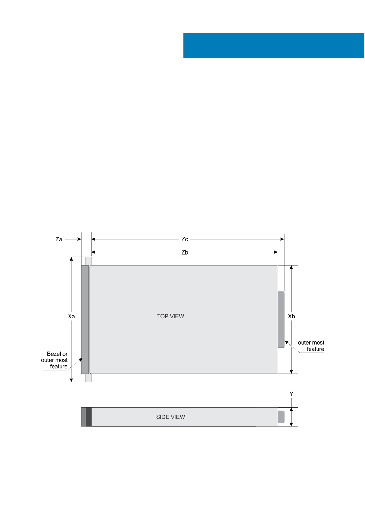
Dimensions of the Dell EMC PowerEdge C6400 enclosure
1
Figure 1. Dimensions of PowerEdge C6400 enclosure
4 Technical specifications
Page 5
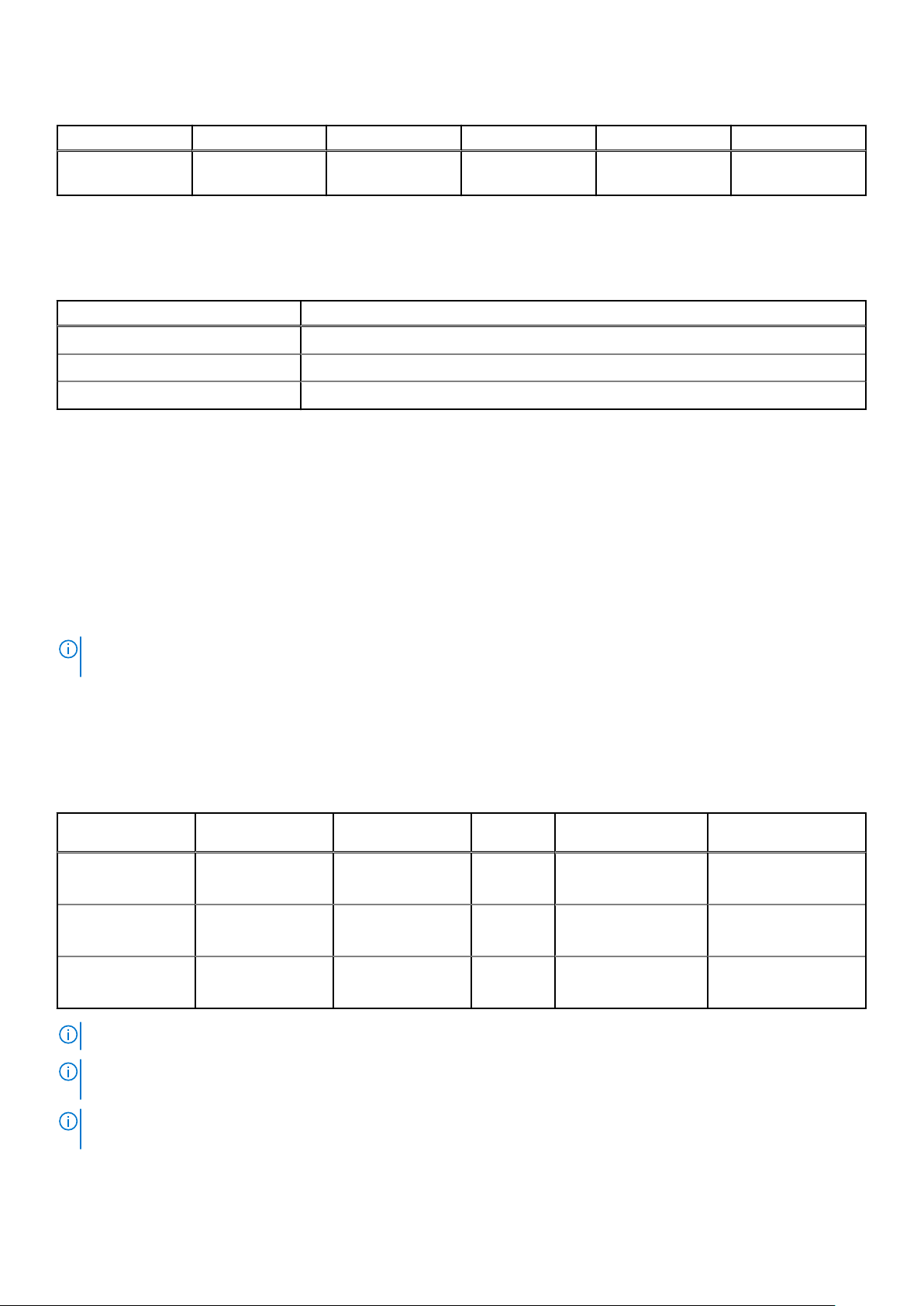
Table 1. Dimensions of the PowerEdge C6400 enclosure
Xa Xb Y Za Zb Zc
482.6 mm (19
inches)
448 mm (17.63
inches)
86.8 mm (3.41
inches)
26.8 mm (1.05
inches)
763.2 mm (30.28
inches)
797.3 mm (31.38
inches)
Chassis weight
Table 2. Chassis weight of the Dell EMC PowerEdge C6400 enclosure with PowerEdge C6420 sleds
System Maximum weight (with all sleds and drives)
12 x 3.5-inch hard drive systems 43.62 Kg (96.16 lb)
24 x 2.5-inch hard drive systems 41.46 Kg (91.40 lb)
No backplane systems 34.56 Kg (76.19 lb)
Supported operating systems
The Dell EMC PowerEdge C6400 supports the following operating systems:
● Canonical Ubuntu LTS
● Citrix XenServer
● Microsoft Windows Server with Hyper-V
● Red Hat Enterprise Linux
● SUSE Linux Enterprise Server
● VMware ESXi
NOTE:
For more information about the specific versions and additions, see https://www.dell.com/support/home/drivers/
supportedos/poweredge-c6400
PSU specifications
The Dell EMC PowerEdge C6400 enclosure supports two AC power supply units (PSUs).
Table 3. PSU specifications
PSU wattage Class Heat dissipation
(maximum)
2400 W AC Platinum 9000 BTU/hr 50/60 Hz
2000 W AC Platinum 7500 BTU/hr 50/60 Hz
1600 W AC Platinum 6000 BTU/hr 50/60 Hz
NOTE: Heat dissipation is calculated using the PSU wattage rating.
NOTE: This system is also designed to connect to the IT power systems with a phase to phase voltage not exceeding 240
V.
Frequency Voltage Maximum input
100–240 V AC,
autoranging
100–240 V AC,
autoranging
100–240 V AC,
autoranging
current
14 A–16 A
11.5 A
10 A
NOTE: If a system with 2400 W AC PSU operates at low line 100–120 V AC, then the power rating per PSU is derated to
1400 W.
Technical specifications 5
Page 6
NOTE: If a system with 2000 W AC PSU operates at low line 100–120 V AC, then the power rating per PSU is derated to
1000 W.
NOTE: If system with 1600 W AC PSU operates at low line 100–120 V AC, then the power rating per PSU is derated to 800
W.
Chassis management board specifications
Figure 2. Chassis management board specifications
Fan cage 1 connector for fans 1 and 2 2. Left midplane signal cable
1.
3. Chassis management board signal cable to backplane 4. Chassis management board power connector from PIB
5. Chassis management board signal cable to PIB 6. FPGA connector
7. MCU connector 8. COM connector
9. Firmware jumpers 10. Right midplane signal cable
11. Fan cage 2 connector for fans 3 and 4
Drives and storage specifications
The Dell EMC PowerEdge C6400 enclosure supports SAS and SATA hard drives and Solid State Drives (SSDs).
Table 4. Supported drive options for the Dell EMC PowerEdge C6400 enclosure
Maximum number of drives in the enclosure Maximum number of drives assigned per sled
12 x 3.5-inch drive systems Three SAS or SATA hard drives and SSDs per sled
24 x 2.5-inch drive systems Six SAS or SATA hard drives and SSDs per sled
24 x 2.5-inch drive systems with NVMe The NVMe backplane supports either of these configurations:
● Two NVMe drives and four SAS or SATA hard drives and
SSDs per sled
● Six SAS or SATA hard drives and SSDs per sled
M.2 SATA drive (optional) The supported capacity of the M.2 SATA card is up to 240 GB
NOTE: The M.2 SATA card can be installed on the x16
riser slot (slot 5).
Micro-SD card (optional) for boot (up to 64 GB) One on each PCIe riser of each sled
6 Technical specifications
Page 7

Table 5. Supported RAID options with M.2 SATA drives
Options Single M.2 SATA drive without RAID Dual M.2 SATA drives with hardware
Hardware RAID No Yes
RAID Mode N/A RAID 1
Number of drives supported 1 2
Supported CPUs CPU 1 CPU 1 and CPU 2
RAID
Midplane specifications
Figure 3. Midplane specifications
Midplane signal connector 2 2. Thermal sensor cable connector
1.
3. Chassis management board cable connector 4. Midplane +12 V power cable connector
5. Midplane power cable ground connector
Environmental specifications
The sections below contains information about the environmental specifications of the system.
NOTE:
For additional information about environmental certifications, please refer to the Product Environmental Datasheet
located with the Manuals & Documents on www.dell.com/poweredgemanuals
Standard operating temperature specifications
NOTE:
1. Not available: Indicates that the configuration is not offered by Dell EMC.
2. Not supported: Indicates that the configuration is not thermally supported.
NOTE: All components including the DIMMs, communication cards, M.2 SATA, and PERC cards can be supported with
sufficient thermal margin if the ambient temperature is equal to or below to the maximum continuous operating temperature
listed in these tables except for the Mellanox DP LP card and Intel Rush Creek card.
Technical specifications 7
Page 8

Table 6. Standard operating temperature specifications
Standard operating temperature Specifications
Temperature ranges (for altitude less than 950 m or 3117 ft) 10°C–35°C (50°F–95°F) with no direct sunlight on the
equipment.
NOTE: Some configurations require a lower ambient temperature. For more information, see the following tables.
Table 7. Maximum continuous operating temperature for nonfabric dual processor configuration
TDP
Watts
205 W
Process
or
model
8280
8280L
8280M
8270
8268
Heat sink
model
CPU1:
FMM2M |
CPU2:
V2DRD
CPU1:
FMM2M |
CPU2:
V2DRD
CPU1:
FMM2M |
CPU2:
V2DRD
CPU1:
FMM2M |
CPU2:
V2DRD
CPU1:
FMM2M |
CPU2:
V2DRD
Max
memo
ry/
proce
ssor
CPU1:
6 |
CPU2:
8
CPU1:
6 |
CPU2:
8
CPU1:
6 |
CPU2:
8
CPU1:
6 |
CPU2:
8
CPU1:
6 |
CPU2:
8
3.5-inch chassis 2.5-inch chassis
12x
Drive
s
Not
Suppo
rted
(2°C)
8x
Drive
s
Not
Suppo
rted
(10°C
)
4x
Drive
s
Not
Supp
orted
(11°C
)
24x
Driv
es
Not
Supp
orted
(19°
C)
20x
Driv
16x
Drive
es
20 21 21 21 21 30
20 21 21 21 21 30
20 21 21 21 21 30
20 21 21 21 21 30
20 21 21 21 21 30
12x
Drive
s
No-BP
Chassis
8x
es
4x
Driv
es
N/A
Driv
s
200 W 6254
8276
8276L
165 W
8276M
8260
CPU1:
FMM2M |
CPU2:
V2DRD
CPU1:
JYKMM |
CPU2:
V2DRD
CPU1:
JYKMM |
CPU2:
V2DRD
CPU1:
JYKMM |
CPU2:
V2DRD
CPU1:
JYKMM |
CPU2:
V2DRD
CPU1:
6 |
CPU2:
8
CPU1:
8 |
CPU2:
8
CPU1:
8 |
CPU2:
8
CPU1:
8 |
CPU2:
8
CPU1:
8 |
CPU2:
8
Not
Suppo
rted(6
°C)
Not
Suppo
rted(11
°C)
Not
Suppo
rted(1
4°C)
Not
Suppo
rted(1
8°C)
Not
Supp
orted
(15°
C)
Not
Supp
orted
(19°
C)
20 21 22 22 22 22 30
30 30 30 30 30 35 35
30 30 30 30 30 35 35
30 30 30 30 30 35 35
30 30 30 30 30 35 35
8 Technical specifications
Page 9

Table 7. Maximum continuous operating temperature for nonfabric dual processor
configuration (continued)
TDP
Watts
Process
or
model
8260L
8260M
8260C
6252
6248
Heat sink
model
CPU1:
JYKMM |
CPU2:
V2DRD
CPU1:
JYKMM |
CPU2:
V2DRD
CPU1:
JYKMM |
CPU2:
V2DRD
CPU1:
JYKMM |
CPU2:
V2DRD
CPU1:
JYKMM |
CPU2:
V2DRD
Max
memo
ry/
proce
ssor
CPU1:
8 |
CPU2:
8
CPU1:
8 |
CPU2:
8
CPU1:
8 |
CPU2:
8
CPU1:
8 |
CPU2:
8
CPU1:
8 |
CPU2:
8
3.5-inch chassis 2.5-inch chassis
12x
Drive
s
8x
Drive
21 23 30 30 30 30 30 35 35
21 23 30 30 30 30 30 35 35
4x
24x
Drive
s
s
20x
Driv
Driv
es
30 30 30 30 30 35 35
30 30 30 30 30 35 35
30 30 30 30 30 35 35
es
16x
Drive
s
12x
Drive
No-BP
Chassis
8x
es
4x
Driv
es
N/A
Driv
s
150 W
125 W
6240
6242
6244
6240C
6230
5220
CPU1:
JYKMM |
CPU2:
V2DRD
CPU1:
JYKMM |
CPU2:
V2DRD
CPU1:
FMM2M |
CPU2:
V2DRD
CPU1:
FMM2M |
CPU2:
V2DRD
CPU1:
JYKMM |
CPU2:
V2DRD
CPU1:
JYKMM |
CPU2:
V2DRD
CPU1:
8 |
CPU2:
8
CPU1:
8 |
CPU2:
8
CPU1:
6 |
CPU2:
8
CPU1:
6 |
CPU2:
8
CPU1:
8 |
CPU2:
8
CPU1:
8 |
CPU2:
8
Not
21 23 30 30 30 30 30 35 35
Suppo
rted(1
4°C)
21 23 30 30 30 30 30 35 35
21 23 30 30 30 30 30 35 35
21 23 30 30 30 30 30 35 35
25 30 30 30 30 35 35 35 35 35
25 30 30 30 30 35 35 35 35 35
5218
CPU1:
JYKMM |
CPU2:
V2DRD
CPU1:
8 |
CPU2:
8
25 30 30 30 30 35 35 35 35 35
Technical specifications 9
Page 10

Table 7. Maximum continuous operating temperature for nonfabric dual processor
configuration (continued)
TDP
Watts
115 W 5217
Process
or
model
5218B
8253
6238T
6230N
Heat sink
model
CPU1:
JYKMM |
CPU2:
V2DRD
CPU1:
JYKMM |
CPU2:
V2DRD
CPU1:
JYKMM |
CPU2:
V2DRD
CPU1:
JYKMM |
CPU2:
V2DRD
CPU1:
FMM2M |
CPU2:
V2DRD
Max
memo
ry/
proce
ssor
CPU1:
8 |
CPU2:
8
CPU1:
8 |
CPU2:
8
CPU1:
8 |
CPU2:
8
CPU1:
8 |
CPU2:
8
CPU1:
6 |
CPU2:
8
3.5-inch chassis 2.5-inch chassis
12x
Drive
s
25 30 30 30 30 35 35 35 35 35
25 30 30 30 30 35 35 35 35 35
25 30 30 30 30 35 35 35 35 35
25 30 30 30 30 35 35 35 35 35
25 30 30 30 30 35 35 35 35 35
8x
Drive
s
4x
Drive
s
24x
Driv
es
20x
Driv
es
16x
Drive
s
12x
Drive
s
8x
Driv
es
4x
Driv
es
Chassis
No-BP
N/A
5218T
5218N
105 W
5222
8256
100 W 4216
5215
85 W
5215M
CPU1:
FMM2M |
CPU2:
V2DRD
CPU1:
FMM2M |
CPU2:
V2DRD
CPU1:
FMM2M |
CPU2:
V2DRD
CPU1:
FMM2M |
CPU2:
V2DRD
CPU1:
JYKMM |
CPU2:
V2DRD
CPU1:
JYKMM |
CPU2:
V2DRD
CPU1:
JYKMM |
CPU2:
V2DRD
CPU1:
6 |
CPU2:
8
CPU1:
6 |
CPU2:
8
CPU1:
6 |
CPU2:
8
CPU1:
6 |
CPU2:
8
CPU1:
8 |
CPU2:
8
CPU1:
8 |
CPU2:
8
CPU1:
8 |
CPU2:
8
30 35 35 35 35 35 35 35 35 35
30 35 35 35 35 35 35 35 35 35
30 35 35 35 35 35 35 35 35 35
30 35 35 35 35 35 35 35 35 35
30 35 35 35 35 35 35 35 35 35
35 35 35 35 35 35 35 35 35 35
35 35 35 35 35 35 35 35 35 35
10 Technical specifications
Page 11

Table 7. Maximum continuous operating temperature for nonfabric dual processor
configuration (continued)
TDP
Watts
Process
or
model
5215L
4215
4214
4214C
4210
Heat sink
model
CPU1:
JYKMM |
CPU2:
V2DRD
CPU1:
JYKMM |
CPU2:
V2DRD
CPU1:
JYKMM |
CPU2:
V2DRD
CPU1:
JYKMM |
CPU2:
V2DRD
CPU1:
JYKMM |
CPU2:
V2DRD
Max
memo
ry/
proce
ssor
CPU1:
8 |
CPU2:
8
CPU1:
8 |
CPU2:
8
CPU1:
8 |
CPU2:
8
CPU1:
8 |
CPU2:
8
CPU1:
8 |
CPU2:
8
3.5-inch chassis 2.5-inch chassis
12x
Drive
s
35 35 35 35 35 35 35 35 35 35
35 35 35 35 35 35 35 35 35 35
35 35 35 35 35 35 35 35 35 35
35 35 35 35 35 35 35 35 35 35
35 35 35 35 35 35 35 35 35 35
8x
Drive
s
4x
Drive
s
24x
Driv
es
20x
Driv
es
16x
Drive
s
12x
Drive
s
8x
Driv
es
4x
Driv
es
Chassis
No-BP
N/A
4208
3204
70 W 4209T
CPU1:
JYKMM |
CPU2:
V2DRD
CPU1:
JYKMM |
CPU2:
V2DRD
CPU1:
JYKMM |
CPU2:
V2DRD
CPU1:
8 |
CPU2:
8
CPU1:
8 |
CPU2:
8
CPU1:
8 |
CPU2:
8
35 35 35 35 35 35 35 35 35 35
35 35 35 35 35 35 35 35 35 35
35 35 35 35 35 35 35 35 35 35
Table 8. Maximum continuous operating temperature for non-fabric single processor configuration
No-BP
Chassis
TDP Watts
205W
Processo
r model
8280
8280L
8280M
Heat
sink
model
CPU1:
FMM2M
CPU1:
FMM2M
CPU1:
FMM2M
Max
memor
y/
proces
sor
CPU1:
6
CPU1:
6
CPU1:
6
3.5-inch chassis 2.5-inch chassis
12x
Drive
8x
4x
24x
Driv
Driv
s
es
30 30 30 35 35 35 35 35 35 35
30 30 30 35 35 35 35 35 35 35
30 30 30 35 35 35 35 35 35 35
Driv
es
20x
Drive
es
16x
Driv
s
es
12x
Drive
s
8x
Drive
s
4x
Drive
s
N/A
8270
CPU1:
FMM2M
CPU1:
6
30 30 30 35 35 35 35 35 35 35
Technical specifications 11
Page 12

Table 8. Maximum continuous operating temperature for non-fabric single processor
configuration (continued)
TDP Watts
200 W 6254
165 W
Processo
r model
8268
6212U
8276
8276L
8276M
8260
8260L
8260M
Heat
sink
model
CPU1:
FMM2M
CPU1:
FMM2M
CPU1:
JYKMM
CPU1:
JYKMM
CPU1:
JYKMM
CPU1:
JYKMM
CPU1:
JYKMM
CPU1:
JYKMM
CPU1:
JYKMM
Max
memor
y/
proces
sor
CPU1:
6
CPU1:
6
CPU1:
8
CPU1:
8
CPU1:
8
CPU1:
8
CPU1:
8
CPU1:
8
CPU1:
8
3.5-inch chassis 2.5-inch chassis
12x
Drive
8x
4x
24x
Driv
Driv
s
es
30 30 30 35 35 35 35 35 35 35
30 30 30 35 35 35 35 35 35 35
30 35 35 35 35 35 35 35 35 35
30 35 35 35 35 35 35 35 35 35
30 35 35 35 35 35 35 35 35 35
30 35 35 35 35 35 35 35 35 35
30 35 35 35 35 35 35 35 35 35
30 35 35 35 35 35 35 35 35 35
30 35 35 35 35 35 35 35 35 35
Driv
es
20x
Drive
es
16x
Driv
s
es
12x
Drive
s
8x
Drive
s
4x
Drive
Chassis
s
No-BP
N/A
150 W
125W
8260C
6210U
6252
6248
6240
6242
6244
6240C
6230
5220
5218
CPU1:
JYKMM
CPU1:
JYKMM
CPU1:
JYKMM
CPU1:
JYKMM
CPU1:
JYKMM
CPU1:
JYKMM
CPU1:
FMM2M
CPU1:
FMM2M
CPU1:
JYKMM
CPU1:
JYKMM
CPU1:
JYKMM
CPU1:
8
CPU1:
8
CPU1:
8
CPU1:
8
CPU1:
8
CPU1:
8
CPU1:
6
CPU1:
6
CPU1:
8
CPU1:
8
CPU1:
8
30 35 35 35 35 35 35 35 35 35
30 35 35 35 35 35 35 35 35 35
30 35 35 35 35 35 35 35 35 35
30 35 35 35 35 35 35 35 35 35
30 35 35 35 35 35 35 35 35 35
30 35 35 35 35 35 35 35 35 35
30 35 35 35 35 35 35 35 35 35
30 35 35 35 35 35 35 35 35 35
35 35 35 35 35 35 35 35 35 35
35 35 35 35 35 35 35 35 35 35
35 35 35 35 35 35 35 35 35 35
5218B
12 Technical specifications
CPU1:
JYKMM
CPU1:
8
35 35 35 35 35 35 35 35 35 35
Page 13

Table 8. Maximum continuous operating temperature for non-fabric single processor
configuration (continued)
TDP Watts
115 W 5217
105 W
100 W 4216
Processo
r model
8253
6238T
6230N
5218T
5218N
5222
8256
Heat
sink
model
CPU1:
JYKMM
CPU1:
JYKMM
CPU1:
JYKMM
CPU1:
FMM2M
CPU1:
FMM2M
CPU1:
FMM2M
CPU1:
FMM2M
CPU1:
FMM2M
CPU1:
JYKMM
Max
memor
y/
proces
sor
CPU1:
8
CPU1:
8
CPU1:
8
CPU1:
6
CPU1:
6
CPU1:
6
CPU1:
6
CPU1:
6
CPU1:
8
3.5-inch chassis 2.5-inch chassis
12x
Drive
8x
4x
24x
Driv
Driv
s
es
35 35 35 35 35 35 35 35 35 35
35 35 35 35 35 35 35 35 35 35
35 35 35 35 35 35 35 35 35 35
30 35 35 35 35 35 35 35 35 35
30 35 35 35 35 35 35 35 35 35
30 35 35 35 35 35 35 35 35 35
30 35 35 35 35 35 35 35 35 35
30 35 35 35 35 35 35 35 35 35
30 35 35 35 35 35 35 35 35 35
Driv
es
20x
Drive
es
16x
Driv
s
es
12x
Drive
s
8x
Drive
s
4x
Drive
Chassis
s
No-BP
N/A
5215
5215M
5215L
4215
85 W
70 W 4209T
4214
4214C
4210
4208
3204
CPU1:
JYKMM
CPU1:
JYKMM
CPU1:
JYKMM
CPU1:
JYKMM
CPU1:
JYKMM
CPU1:
JYKMM
CPU1:
JYKMM
CPU1:
JYKMM
CPU1:
JYKMM
CPU1:
JYKMM
CPU1:
8
CPU1:
8
CPU1:
8
CPU1:
8
CPU1:
8
CPU1:
8
CPU1:
8
CPU1:
8
CPU1:
8
CPU1:
8
35 35 35 35 35 35 35 35 35 35
35 35 35 35 35 35 35 35 35 35
35 35 35 35 35 35 35 35 35 35
35 35 35 35 35 35 35 35 35 35
35 35 35 35 35 35 35 35 35 35
35 35 35 35 35 35 35 35 35 35
35 35 35 35 35 35 35 35 35 35
35 35 35 35 35 35 35 35 35 35
35 35 35 35 35 35 35 35 35 35
35 35 35 35 35 35 35 35 35 35
Technical specifications 13
Page 14

Table 9. Configuration Restrictions with Mellanox Navi Dual Port Card with Active (Optical) connectivity
TDP Watts
205 W
200 W
173 W
165 W
160 W
150 W
140 W
135 W
130 W
3.5-inch chassis 2.5-inch chassis
12x HDDs 8x HDDs 4x HDDs 24x HDDs 16x HDDs 8x HDDs 4x HDDs N/A
Not
supported
Not
supported
Not
supported
Not
supported
Not
supported
Not
supported
Not
supported
Not
supported
Not
supported
Not
supported
Not
supported
Not
supported
Not
supported
Not
supported
Not
supported
23 25 28 29 29 30 33
24 25 29 30 30 31 33
24 26 30 31 31 31 34
Not
supported
Not
supported
Not
supported
Not
supported
Not
supported
Not
supported
Not
supported
Not
supported
Not
supported
24 25 25 26 29
24 25 26 26 30
26 27 28 28 31
Not
supported
Not
supported
Not
supported
Not
supported
Not
supported
24 24 28
Not
supported
Not
supported
No-BP
Chassis
23
23
125 W 20 25 27 30 31 32 32 35
115 W 21 27 28 32 33 34 34 >35
113 W 21 27 28 32 33 34 34 >35
105 W 22 28 30 34 35 >35 >35 >35
85 W 23 32 33 >35 >35 >35 >35 >35
70 W 25 34 >35 >35 >35 >35 >35 >35
Table 10. Configuration Restrictions with Intel Rush Creek
TDP Watts
12x HDDs 8x HDDs 4x HDDs 24x HDDs 16x HDDs 8x HDDs 4x HDDs N/A
205 W Not
supported
200 W Not
supported
173 W Not
supported
165 W Not
supported
160 W Not
supported
3.5-inch chassis 2.5-inch chassis
Not
supported
Not
supported
Not
supported
Not
supported
Not
supported
Not
supported
Not
supported
Not
supported
Not
supported
Not
supported
Not
supported
Not
supported
20 20 23 24 28
22 22 24 25 29
22 22 24 26 29
Not
supported
Not
supported
20 20 23
21 21 24
No-BP
Chassis
150 W Not
supported
140 W Not
supported
14 Technical specifications
supported
supported
Not
Not
Not
supported
Not
supported
24 24 26 27 30
26 26 27 28 31
Page 15

Table 10. Configuration Restrictions with Intel Rush Creek (continued)
TDP Watts
12x HDDs 8x HDDs 4x HDDs 24x HDDs 16x HDDs 8x HDDs 4x HDDs N/A
135 W Not
supported
130 W Not
supported
125 W Not
supported
115W Not
supported
105 W 20 23 24 30 33 33 34 >35
85 W 24 26 27 34 >35 >35 >35 >35
70 W 25 28 29 >35 >35 >35 >35 >35
3.5-inch chassis 2.5-inch chassis
Not
supported
Not
supported
Not
supported
21 23 29 31 31 32 34
20 26 26 28 29 32
20 27 27 29 29 33
21 28 28 30 30 33
Table 11. Configuration Restrictions with Intel NVMe SSD AIC P4800X
TDP Watts
12x HDDs 8x HDDs 4x HDDs 24x HDDs 16x HDDs 8x HDDs 4x HDDs N/A
205 W Not
supported
3.5-inch chassis 2.5-inch chassis
Not
supported
Not
supported
Not
supported
Not
supported
Not
supported
Not
supported
No-BP
Chassis
No-BP
Chassis
Not
supported
200 W Not
supported
173 W Not
supported
165 W Not
supported
160 W Not
supported
150 W Not
supported
140 W Not
supported
135 W Not
supported
130 W Not
supported
125 W Not
supported
115 W Not
supported
105 W Not
supported
Not
supported
Not
supported
Not
supported
Not
supported
Not
supported
Not
supported
Not
supported
Not
supported
Not
supported
Not
supported
Not
supported
Not
supported
Not
supported
Not
supported
Not
supported
Not
supported
Not
supported
Not
supported
Not
supported
Not
supported
Not
supported
Not
supported
Not
supported
Not
supported
Not
supported
Not
supported
Not
supported
20 20 20 20 25
20 20 20 20 25
20 20 20 20 25
20 25 25 25 30
25 25 25 25 30
25 25 25 25 30
Not
supported
Not
supported
Not
supported
Not
supported
20 20 20 25
Not
supported
Not
supported
Not
supported
Not
supported
Not
supported
Not
supported
Not
supported
Not
supported
Not
supported
20
20
25
85 W Not
supported
70 W Not
supported
Not
supported
Not
supported
Not
supported
Not
supported
30 30 30 30 >35
>35 >35 >35 >35 >35
Technical specifications 15
Page 16

Expanded operating temperature specifications
Table 12. Expanded operating temperature
Expanded operating temperature Specifications
Continuous operation 5°C–40°C at 5% to 85% RH with maximum 29°C dew point.
NOTE: Outside the standard operating temperature (10°C–35°C), the system can
operate continuously in temperatures as low as 5°C and as high as 40°C.
For temperatures between 35°C and 40°C, derate maximum allowable temperature by
1°C per 175 m above 950 m (1°F per 319 ft).
≤ 1% of annual operating hours –5°C–45°C at 5% to 90% RH with maximum 29°C dew point.
NOTE: Outside the standard operating temperature (10°C–35°C), the system can
operate down to –5°C or up to 45°C for a maximum of 1% of its annual operating
hours.
For temperatures between 40°C-45°C, derate maximum allowable temperature by 1°C
per 125 m above 950 m (1°F per 228 ft).
NOTE: When operating in the expanded temperature range, system performance may be impacted.
NOTE: When operating in the expanded temperature range, ambient temperature warnings may be reported in the System
Event Log.
Operating temperature derating specifications
Table 13. Operating temperature
Operating temperature derating Specifications
< 35°C (95°F) Maximum temperature is reduced by 1°C/300 m (1°F/547 ft)
above 950 meters (3,117 ft).
35°C–40°C (95°F–104°F) Maximum temperature is reduced by 1°C/175 m (1°F/319 ft)
above 950 meters (3,117 ft).
> 45°C (113°F) Maximum temperature is reduced by 1°C/125 m (1°F/228 ft)
above 950 meters (3,117 ft).
Relative humidity specifications
Table 14. Relative humidity specifications
Relative humidity Specifications
Storage 5% to 95% RH with 33°C (91°F) maximum dew point.
Atmosphere must be noncondensing always.
Operating 10% to 80% relative humidity with 29°C (84.2°F) maximum
dew point.
16 Technical specifications
Page 17

Temperature specifications
Table 15. Temperature specifications
Temperature Specifications
Storage –40°C–65°C (–40°F to 149°F)
Continuous operation (for altitude less than 950 m or 3117 ft) 10°C–35°C (50°F to 95°F) with no direct sunlight on the
equipment.
Fresh air For information about fresh air, see Expanded Operating
Temperature section.
Maximum temperature gradient (operating and storage) 20°C/h (68°F/h)
NOTE: Some configurations require a lower ambient temperature for more information, see the Standard operating
temperature specifications.
Particulate and gaseous contamination specifications
Table 16. Particulate contamination specifications
Particulate contamination Specifications
Air filtration Data center air filtration as defined by ISO Class 8 per ISO
14644-1 with a 95% upper confidence limit.
NOTE: This condition applies only to data center environments. Air filtration requirements do not apply to IT equipment
designed to be used outside a data center, in environments such as an office or factory floor.
NOTE: Air entering the data center must have MERV11 or MERV13 filtration.
Conductive dust Air must be free of conductive dust, zinc whiskers, or other
conductive particles.
NOTE: This condition applies to data center and non-data center environments.
Corrosive dust Air must be free of corrosive dust.
Residual dust present in the air must have a deliquescent point less than 60% relative humidity.
NOTE: This condition applies to data center and non-data center environments.
Table 17. Gaseous contamination specifications
Gaseous contamination Specifications
Copper coupon corrosion rate <300 Å/month per Class G1 as defined by ANSI/
ISA71.04-2013
Silver coupon corrosion rate <200 Å/month per Class G1 as defined by ANSI/
ISA71.04-2013
NOTE: Maximum corrosive contaminant levels measured at ≤50% relative humidity.
Technical specifications 17
Page 18

Maximum vibration specifications
Table 18. Maximum vibration specifications
Maximum vibration Specifications
Operating 0.26 Grms at 5 Hz to 350 Hz (all operation orientations).
Storage 1.88 Grms at 10 Hz to 500 Hz for 15 min (all six sides tested).
Maximum shock specifications
Table 19. Maximum shock specifications
Maximum shock Specifications
Operating 24 executed shock pulses 6 G in the positive and negative x,
y, z axis for up to 11 ms (four pulses on each side of the
system).
Storage 6 consecutively executed shock pulses of 71 G in the positive
and negative x, y, z axes for up to 2 ms (one pulse on each
side of the system).
Maximum altitude specifications
Table 20. Maximum altitude specifications
Maximum altitude Specifications
Operating 3048 m (10,000 ft)
Storage 12,000 m (39,370 ft)
Fresh Air Operation
Fresh Air operation restrictions
● Processors with a TDP greater than 105 W are not supported
● Support for processors of 85 W and below without PERC restrictions
● 3.5-inch drive configuration is not supported
● 114-mm heat sink is required for the processor in CPU1 socket
● Kerby-flat OCP is not supported
● M.2 card on DCS Mezzanine slot is not supported.
● NVMe SSD is not supported
● AEP DIMM and LRDIMM are not supported
● PCIe cards greater than 25 W are not supported
● H730 PERC and H330 support for 105-W processors
● No PERC restrictions for 85 W and lesser TDP processors
18
Technical specifications
 Loading...