

Dell PowerEdge C6300 User Manual [he]

Dell PowerEdge C6320
Getting Started
With Your System
Začínáme se systémem
Mise en route du système
Erste Schritte mit dem System
Τα πρώτα βήματα στο σύστημά σας
Rozpoczynanie pracy z systemem
Начало работы с системой
Početak rada sa sistemom
Procedimientos iniciales con el sistema
Sisteminizi Kullanmaya Başlarken
תליחת הדובעה םע תכרעמה

Scan to see how-to videos, documentation, and
troubleshooting information.
Naleznete zde videa s postupy, dokumentaci
a informace o řešení potíží.
Scannez pour voir des didacticiels vidéo, obtenir de la
documentation et des informations de dépannage.
Scannen, um Videos zu Hilfe und Anleitungen, Dokumentationen
und Informationen zur Fehlerbehebung zu sehen.
Αναζητήστε βίντεο για τον τρόπο χρήσης του συστήματος,
τεκμηρίωση και πληροφορίες για την αντιμετώπιση προβλημάτων.
Zeskanuj, aby wyświetlić instruktażowe filmy wideo
i informacje o rozwiązywaniu problemów.
Сканируйте, чтобы просмотреть обучающее видео,
документацию и информацию по устранению неисправностей.
Skenirajte da biste videli video uputstva, dokumentaciju
i informacije o rešavanju problema.
Escaneo para ver vídeos sobre procedimientos, documentación
e información para la solución de problemas.
Tarama nasıl yapılır videoları, belgeler ve
sorun giderme bilgilerini görmek için.
קורס ידכ תוארל עדימ יבגל ינוטרס הכרדה ,דועית ןורתפו תויעב.

Dell PowerEdge
C6320
Getting Started
With Your System

Notes, Cautions, and Warnings
NOTE: A NOTE indicates important information that helps you make better
use of your computer.
CAUTION: A CAUTION indicates potential damage to hardware or
loss of data if instructions are not followed.
WARNING: A WARNING indicates a potential for property damage,
personal injury, or death.

______________
Copyright © 2015 Dell Inc. All rights reserved. This product is protected by U.S. and international
copyright and intellectual property laws. Dell™ and the Dell logo are trademarks of Dell Inc. in the
United States and/or other jurisdictions. All other marks and names mentioned herein may be
trademarks of their respective companies.
Regulatory Model: B08S Regulatory Type: B08S003
2015 - 03 P/N CFK9F Rev. A00
CAUTION: Restricted Access Location
This server is intended for installation only in restricted access locations as defined in
Cl. 1.2.7.3 of IEC 60950-1: 2001 where both these conditions apply:
• Access can only be gained by service persons or by users who have been
instructed about the reasons for the restrictions applied to the location and
about any precautions that shall be taken.
• Access is through the use of a tool or lock and key, or other means of security,
and is controlled by the authority responsible for the location.
Installation and Configuration
WARNING: Before performing the following procedure, review and follow
the safety instructions that came with the system.
Installing the Tool-Less Rail Solution
WARNING: Whenever you need to lift the system, get others to assist
you. To avoid injury, do not attempt to lift the system by yourself.
WARNING: The system is not fixed to the rack or mounted on the
rails. To avoid personal injury or damage to the system, you must
adequately support the system during installation and removal.
WARNING: To avoid a potential electrical shock hazard, a third wire
safety grounding conductor is necessary for the rack installation.
The rack equipment must provide sufficient airflow to the system to
maintain proper cooling.
CAUTION: When installing rails in a square-hole rack it is important
to ensure that the square peg slides through the square holes.
6 | Getting Started With Your System
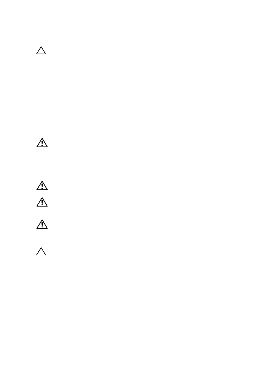
1 Push the latch release buttons on the midpoints of the end piece to open the
rail latches. See Figure 1.
2 Align the end pieces of the rails on the vertical rack flanges to seat the pegs
in the bottom hole of the first U and the top hole of the second U.
NOTE: The rails can be used in both square-hole (item 1 in the
following figure) and round-hole racks (item 2 in the following figure).
Figure 1. Pushing the Latch Release Buttons
NOTE: To remove the rails, push the latch release button on the
midpoints of the end piece and unseat each rail.
Getting Started With Your System | 7

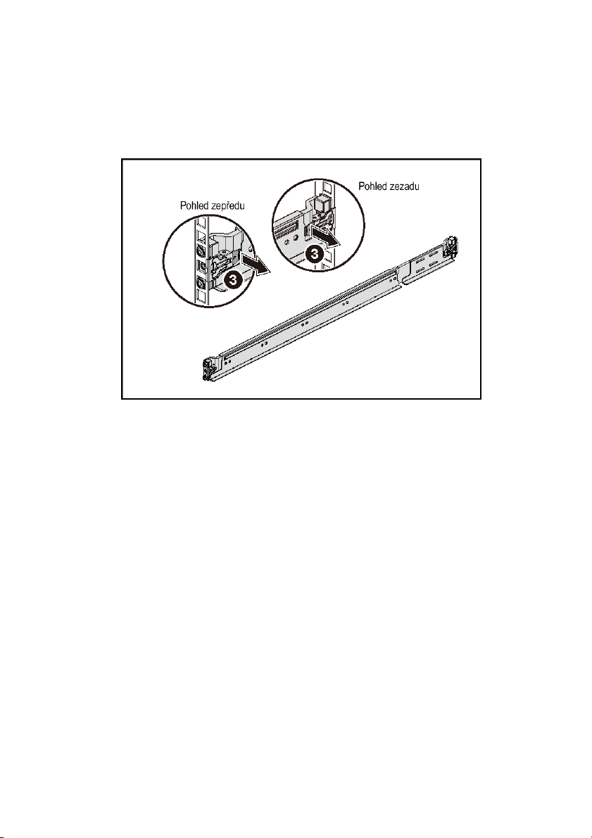
3 Engage the end of the rails and release the latch release button to have the
latches locked in place. See Figure 2.
Figure 2. Releasing the Latch Release Buttons
4 On each vertical rack flange on the back, put two screw bases into the two
square holes right above the rail. See Figure 3.
5 Install the chassis stabilizer shipping brackets (optional) on the back rack
flanges.
8 | Getting Started With Your System

6 Install and tighten the screws.
NOTE: To transport systems already installed in the rack, ensure that
the two chassis stabilizer shipping brackets (optional) are in place.
Figure 3. Installing the Chassis Stabilizer Shipping Brackets
Getting Started With Your System | 9
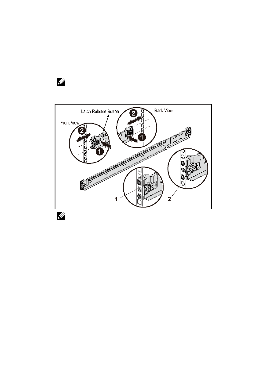
7 Slide the system into the rack. See Figure 4.
8 Tighten the thumbscrews to secure the ears of the system to the front of the
rack flanges.
Figure 4. Installing the Chassis onto the Rack.
10 | Getting Started With Your System
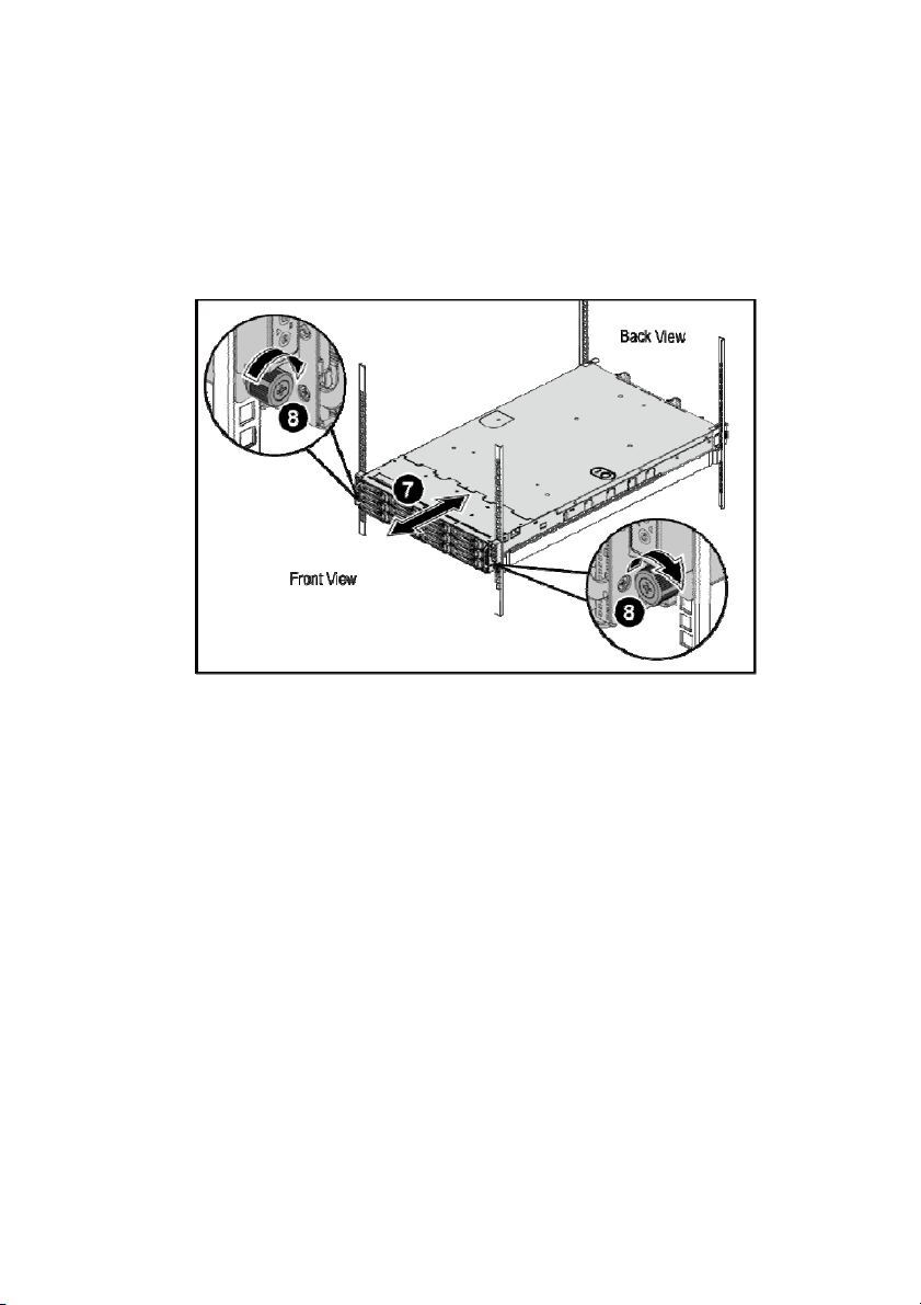
Optional—Connecting the Keyboard, Mouse, and Monitor
Figure 5. Optional—Connecting the Keyboard, Mouse and Monitor
Connect the keyboard, mouse, and monitor (optional).
The connectors on the back of your system have icons indicating which cable to plug
into each connector. Be sure to tighten the screws (if any) on the monitor’s cable
connector.
NOTE: Note that the system supports only one USB port and a micro USB
port. If you require more than one USB outlet at a time, use USB Hub or
Adapter Cable.
Getting Started With Your System | 11

Connecting the Power Cable(s)
Figure 6. Connecting the Power Cable
Connect the system’s power cable(s) to the system and, if a monitor is used, connect
the monitor’s power cable to the monitor. Plug the other end of the power cables into
a grounded electrical outlet or a separate power source such as an uninterrupted power
supply or a power distribution unit.
NOTE: The system supports both AC and HVDC power inputs. Your system
can support up to two 1400 W power supply units (200-240 VAC nominal
input voltage) or up to two 1600 W power supply units (200-240 VAC nominal
input voltage). 1400 W power supply unit is supported only for China.
12 | Getting Started With Your System
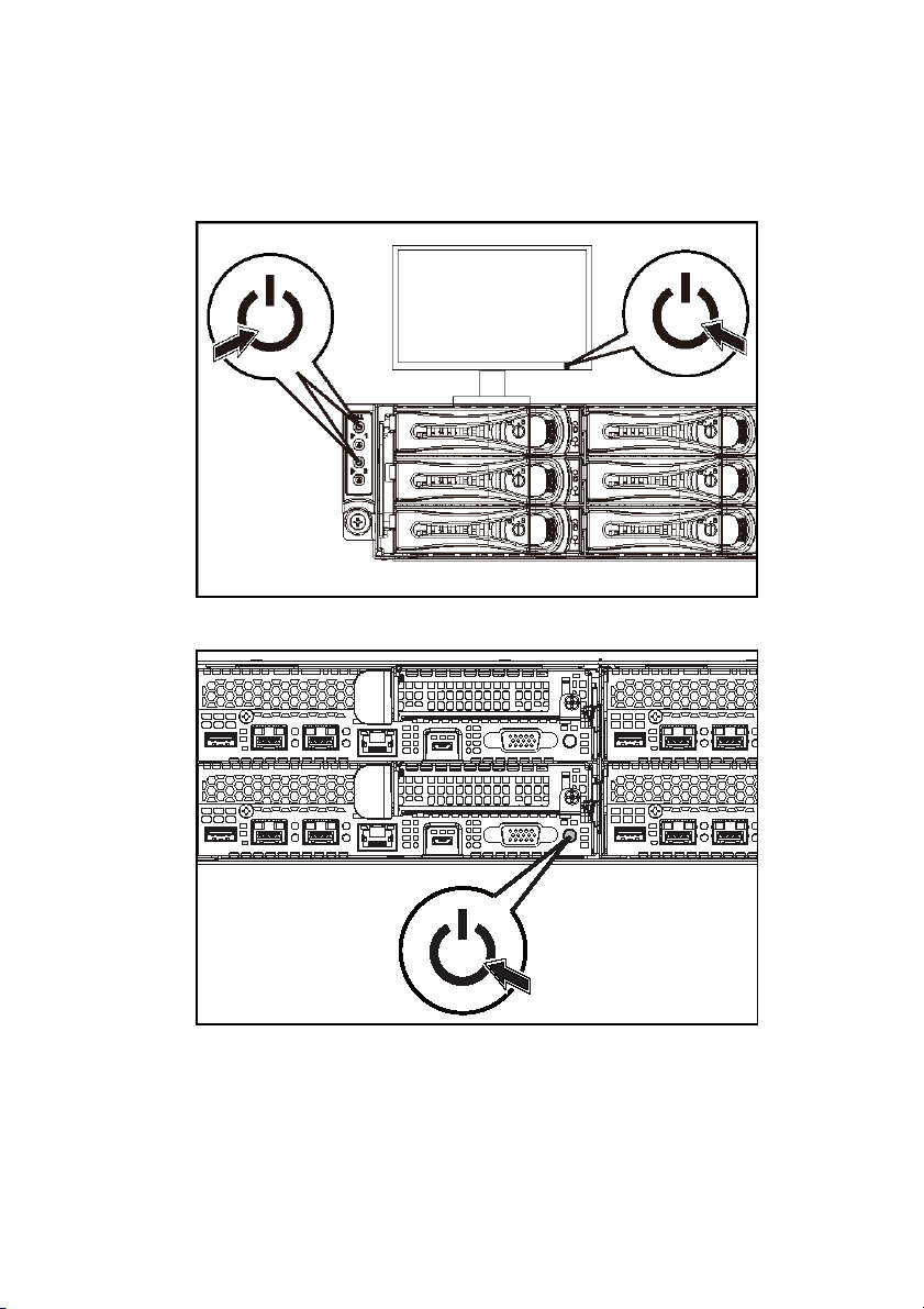
Turning on the System
Figure 7. Pressing the Power Button on the Front of the System
Figure 8. Pressing the Power Button on the Back of the System
Press the power button(s) either on the front or back of the system. The power indicators
should light green.
Getting Started With Your System | 13

Complete the Operating System Setup
To install an operating system for the first time, see the installation and configuration
documentation for your operating system. Be sure the operating system is installed
before installing hardware or software not purchased with the system.
NOTE: See dell.com/ossupport for the latest information on supported operating
systems.
Other Information You May Need
The Hardware Owner’s Manual provides information about system features and
describes how to troubleshoot the system and install or replace system components.
This document is available at dell.com/support/home.
Dell systems management application documentation provides information about
installing and using the systems management software. This document is available
online at dell.com/support/home.
For an immediate access to your system information:
For more information about your system:
WARNING: See the safety and regulatory information that shipped with
your system. Warranty information may be included within this document
or as a separate document.
1. Go to dell.com/support.
2. Enter your system service tag in the Enter your Service Tag field.
3. Click Submit.
The support page that lists the system manuals is displayed.
1. Go to dell.com/support.
2. Select your country from the drop-down menu on the top left corner of
the page.
a. Select your product category.
b. Select your product segment.
c. Select your product.
The support page that lists the various support categories is displayed.
NOTE: Always check for updates on dell.com/support/home and read the
updates first because they often supersede information in other documents.
14 | Getting Started With Your System

NOM Information (Mexico Only)
The following information is provided on the device described in this document in
compliance with the requirements of the official Mexican standards (NOM):
Importer Dell Inc. de México, S.A. de C.V.
Paseo de la Reforma 2620-11° Piso
Col. Lomas Atlas
11950 México, D.F.
Model number B08S
Supply voltage 200-240 V AC with 1400 W (for China
only) or 1600 W Power Supply Unit
Frequency 50/60 Hz
Current consumption 9 Amps with 1400 W Power Supply Unit
10 Amps with 1600 W Power Supply Unit
Technical Specifications
Processor Two Intel Xeon E5-2600 v3
Memory
Architecture 1600 MT/s, 1866 MT/s, or
2133 MT/s DDR4 Registered
DIMMs
Support for advanced ECC or
memory optimized operation
Memory module sockets Twelve 288-pin
Getting Started With Your System | 15

Memory module capacities (RDIMMs) 8 GB and 16 GB dual-rank
Minimum RAM
Maximum RAM
16 GB
Up to 256 GB
Power
NOTE: The system does not support a mixed installation of 1400 W and
1600 W power supply units.
NOTE: The 1400 W and 1600 W power supply units are hot swappable,
and supports hot swap in any condition if the system has the power
throttling feature.
AC power supply (per power supply)
Wattage 1400 W (for China only)
Voltage 200-240 VAC, 50/60 Hz, maximum
input current: 9 Amps
Heat dissipation 6024.376 BTU/hr maximum
Maximum inrush current
Initial In-rush Current cannot exceed
55 Amps (peak). Secondary In-rush
Current cannot exceed 25 Amps
(peak).
Wattage 1600 W
Voltage
16 | Getting Started With Your System
200-240 VAC, 50/60 Hz, maximum
input current: 10 Amps

Heat dissipation 6033.979 BTU/hr maximum
Maximum inrush current
Initial In-rush current and secondary
In-rush current cannot exceed
50 Amps (peak).
HVDC power supply (per power supply)
Wattage 1400 W (for China only)
Voltage 240 VDC, 50/60 Hz, maximum input
current: 9 Amps
Heat dissipation 5440.614 BTU/hr maximum
Maximum inrush current
Initial In-rush Current cannot exceed
55 Amps (peak). Secondary In-rush
Current cannot exceed 25 Amps
(peak).
Battery (per system board)
System battery CR 2032 3.0-V lithium ion coin cell
Physical
Height 8.68 cm (3.42 in)
Width 44.8 cm (17.6 in)
Depth 79.0 cm (31.1 in)
Weight (maximum configuration) 41 kg (90.38 lb)
(with 12*3.5” HDD)
39 kg (86.00 lb)
(with 24*2.5” HDD)
Getting Started With Your System | 17

Weight (empty) 15.7 kg (34.61 lb)
(with 2.5” HDD bay)
15.1 kg (33.29 lb)
(with 3.5” HDD bay)
Environmental
NOTE: For additional information about environmental measurements for specific
system configurations, see www.dell.com/environmental_datasheets.
Temperature
Operating 10° to 35°C (50° to 95°F) with
a maximum temperature gradation
of 10°C per hour
NOTE: For altitudes above 2950 feet,
the maximum operating temperature
is derated 1°F/550 ft.
CAUTION: The maximum number of
memory modules and hard drives
supported on 1U node configuration,
with 135W and 145W processors,
depends on the power supply installed.
Storage –40° to 65°C (–40° to 149°F) with
a maximum temperature gradation of
20°C per hour
Relative humidity
Operating 20% to 80% (noncondensing) with
a maximum humidity gradation of
10% per hour
Storage 5% to 95% (noncondensing)
Maximum vibration
Operating 0.26 Grms at 5–350 Hz
Storage 1.88 Grms at 10–500 Hz for 15 min
18 | Getting Started With Your System

Maximum shock
Operating One shock pulse in the positive
z axis (one pulse on each side of the
system) of 31 G for 2.6 ms in the
operational orientation
Storage Six consecutively executed shock
pulses in the positive and negative x,
y, and z axes (one pulse on each side
of the system) of 71 G for up to 2 ms;
Six consecutively executed shock
pulses in the positive and negative x,
y, and z axes (one pulse on each side
of the system) of 27 G faired square
wave pulse with velocity change
at 235 inches/second
(597 centimeters/second)
Altitude
Operating -15.2 to 3,048 m
(-50 to 10,000 ft.)
Storage -15.2 to 10,668 m
(-50 to 35,000 ft.)
Airborne Contaminant Level
Class G1 as defined by
ISA-S71.04-1985
Getting Started With Your System | 19


Dell PowerEdge
C6320
Začínáme
se systémem

Poznámky a upozornění
POZNÁMKA: POZNÁMKA označuje důležité informace, které umožňují
lepší využití počítače.
UPOZORNĚNÍ: UPOZORNĚNÍ poukazuje na možnost poškození
hardwaru nebo ztráty dat v případě nedodržení pokynů.
VAROVÁNÍ: VAROVÁNÍ upozorňuje na potenciální nebezpečí
poškození majetku, úrazu nebo smrti.

______________
Copyright © 2015 Dell Inc. Všechna práva vyhrazena. Tento produkt je chráněn pomocí amerických
a mezinárodních autorských práv a zákonů o duševním vlastnictví. Dell™ a logo Dell jsou ochranné
známky společnosti Dell Inc. v USA a jiných oblastech. Všechny ostatní zde zmiňované značky
a názvy mohou být ochrannými známkami příslušných vlastníků.
Regulační model: B08S Regulační typ: B08S003
2015 - 03 Č. dílu CFK9F Rev. A00

UPOZORNĚNÍ: Umístění s omezeným přístupem
Tento server je určen k instalaci pouze na místa s omezeným přístupem, jak jsou
definována v čl. 1.2.7.3 normy IEC 60950-1: 2001, kde platí obě tyto podmínky:
• Přístup mohou získat pouze servisní pracovníci nebo uživatelé, kteří byli poučeni
o důvodech omezení platného pro umístění a o veškerých opatřeních, jež je nutné
dodržovat.
• Přístup je poskytován za použití nástroje nebo zámku a klíče nebo je jinak
zabezpečen a je řízen představitelem zodpovědným za toto umístění.
Instalace a konfigurace
VAROVÁNÍ: Před provedením následujícího postupu si prostudujte
bezpečnostní pokyny dodané se systémem a postupujte podle nich.
Instalace ližinového řešení s přístupem
bez nářadí
VAROVÁNÍ: Při každém zvedání systému požádejte o asistenci.
Systém nezvedejte sami, vyvarujete se tak zranění.
VAROVÁNÍ: Systém není upevněn k racku ani namontován na ližinách.
Chcete-li předejít možnosti zranění osob nebo poškození systému,
je třeba systém během instalace a vyjímání dostatečně stabilizovat.
VAROVÁNÍ: Chcete-li předejít nebezpečí úrazu elektrickým proudem,
je nutné při instalaci do racku použít třetí bezpečnostní zemnicí
vodič. Rackové vybavení musí systému poskytovat dostatečný
průchod vzduchu a zajišťovat tak dostatečné chlazení.
UPOZORNĚNÍ: Při instalaci ližin do racku se čtvercovými otvory
je důležité zajistit, aby byl do čtvercových otvorů zasunuty
čtyřhranné kolíky.
24 | Začínáme se systémem

1 Otevřete západky ližin zatlačením na tlačítka uvolnění západky ve středu
zadních konců ližin. Viz Obrázek 1.
2 Zarovnejte koncovky ližin se svislými přírubami racku a usaďte kolíky do
spodního otvoru prvního tvaru U a do horního otvoru druhého tvaru U.
POZNÁMKA: Ližiny lze použít v racku se čtvercovými (položka 1 na
následujícím obrázku) i kulatými otvory (položka 2 na následujícím
obrázku).
Obrázek 1. Stisknutí tlačítek uvolnění západky
POZNÁMKA: Chcete-li vyjmout ližiny, uvolněte je zatlačením na
tlačítko uvolnění západky ve středu zadního konce kolejničky.
Začínáme se systémem | 25
3 Kolejničky upevníte na místo zasazením jejich zadních konců a uvolněním
uvolňovacího knoflíku. Viz Obrázek 2.
Obrázek 2. Uvolnění tlačítek uvolnění západky
4 Na každou svislou přírubu v zadní části racku vložte do dvou čtvercových
otvorů nad ližinou dvě závitové patice. Viz Obrázek 3.
5 Na zadní příruby racku nainstalujte stabilizační přepravní držáky šasi
(volitelné).
26 | Začínáme se systémem

6 Namontujte a utáhněte šrouby.
POZNÁMKA: Chcete-li přepravovat systémy již nainstalované
v racku, zajistěte, aby byly tyto dva stabilizační přepravní držáky
šasi (volitelné) správně namontovány.
Obrázek 3. Instalace stabilizačních přepravních držáků šasi
Začínáme se systémem | 27

7 Zasuňte systém do racku. Viz Obrázek 4.
8 Pomocí šroubků upevněte držáky na systému k přední části přírub racku.
Obrázek 4. Instalace šasi do racku.
28 | Začínáme se systémem

Volitelné - připojení klávesnice, myši a monitoru
Obrázek 5. Volitelné - připojení klávesnice, myši a monitoru
Připojte klávesnici, myš a monitor (volitelné).
Konektory na zadní straně systému mají ikony znázorňující, který kabel se má připojit
ke kterému konektoru. Zajistěte, aby šroubky na konektoru kabelu monitoru byly dobře
dotaženy (je-li jimi konektor vybaven).
POZNÁMKA: Systém podporuje pouze jeden port USB a jeden port micro
USB. Pokud potřebujete použít více než jeden port USB najednou, použijte
rozbočovač USB nebo redukci.
Začínáme se systémem | 29

Připojení napájecích kabelů
Obrázek 6. Připojení napájecího kabelu
Připojte napájecí kabely k systému, a pokud používáte monitor, připojte napájecí kabel
také k monitoru. Poté zasuňte druhý konec napájecích kabelů do uzemněné elektrické
zásuvky nebo je připojte k samostatnému zdroji napájení, například ke zdroji
nepřerušitelného napájení (UPS) nebo jednotce rozvaděče (PDU).
POZNÁMKA: Systém podporuje vstup napájení střídavého proudu
i stejnosměrného proudu s vysokým napětím. Váš systém podporuje až dvě
1 400W jednotky zdroje napájení (nominální vstupní napětí 200-240 V stř.)
nebo až dvě 1 600W jednotky zdroje napájení (nominální vstupní napětí
200-240 V stř.). 1 400W jednotka zdroje napájení je podporována pouze
v Číně.
30 | Začínáme se systémem
 Loading...