

Page 1

Dell PowerEdge
C6220 II
Using the Baseboard
Management Controller
FILE LOCATION: D:\Projects\User Guide\Server\Dell\C6220II\BMC\C6220II_BMC_HOM_tp.fm
Template Last Updated -03/06/2010
Page 2

FILE LOCATION: D:\Projects\User Guide\Server\Dell\C6220II\BMC\C6220II_BMC_HOM_tp.fm
NOTE: A NOTE indicates important information that helps you make better use of
your computer.
CAUTION: A CAUTION indicates potential damage to hardware or loss of data if
instructions are not followed.
WARNING: A WARNING indicates a potential for property damage, personal
injury, or death.
____________________
Information in this publication is subject to change without notice.
© 2013 Dell Inc. All rights reserved.
Reproduction of these materials in any manner whatsoever without the written permission of Dell Inc.
is strictly forbidden.
Trademarks used in this text: Dell™, the DELL logo, and PowerEdge™ are trademarks of Dell Inc.
Microsoft
either trademarks or registered trademarks of Microsoft Corporation in the United States and/or other
countries. Red Hat
the United States and/or other countries. Oracle and Java are registered trademarks of Oracle and/or
its affiliates. Intel is a registered trademark of Intel Corporation in the U.S. and other countries.
Other trademarks and trade names may be used in this publication to refer to either the entities claiming
the marks and names or their products. Dell Inc. disclaims any proprietary interest in trademarks and
trade names other than its own.
2013 - 07 Rev. A00
®
, Windows®, Windows Server®, MS-DOS®, Windows V ista®, and Internet Explorer® are
®
and Red Hat® Enterprise Linux® are registered trademarks of Red Hat, Inc. in
Page 3

Guide\Server\Dell\C6220II\BMC\C6220II_BMC_HOM_bk0TOC.fm
Contents
Intelligent Platform Management
Interface . . . . . . . . . . . . . . . . . . . . . . . . . . 5
Baseboard Management Controller. . . . . . . . . . . . 5
FILE LOCATION: D:\Projects\User
Supported Platform
. . . . . . . . . . . . . . . . . . . . 5
BMC Key Features and Functions . . . . . . . . . . . . . 5
Using the Web User Interface
Logging in to the Web User Interface
. . . . . . . . . . . . . . . 6
. . . . . . . . . . . 7
Remote Management Controller . . . . . . . . . . . . . 9
Properties
. . . . . . . . . . . . . . . . . . . . . . 10
Chassis . . . . . . . . . . . . . . . . . . . . . . . 11
Configuration
Sessions
. . . . . . . . . . . . . . . . . . . . 12
. . . . . . . . . . . . . . . . . . . . . . 20
Update . . . . . . . . . . . . . . . . . . . . . . . 21
Utilities
. . . . . . . . . . . . . . . . . . . . . . . 23
Server Information
Sensor Monitor
Power
System Event Log
Event Management
Trap Settings
Email Settings
. . . . . . . . . . . . . . . . . . . . 24
. . . . . . . . . . . . . . . . . . . 24
. . . . . . . . . . . . . . . . . . . . . . . . 32
. . . . . . . . . . . . . . . . . . . . . 33
. . . . . . . . . . . . . . . . . 34
. . . . . . . . . . . . . . . . . . . . 36
. . . . . . . . . . . . . . . . . . . . 37
Contents
3
Page 4

FILE LOCATION: D:\Projects\User
Guide\Server\Dell\C6220II\BMC\C6220II_BMC_HOM_bk0TOC.fm
Serial Over LAN . . . . . . . . . . . . . . . . . . . . . 40
vKVM & vMedia
. . . . . . . . . . . . . . . . . . . 41
Using the Video Viewer
Video Viewer Menu
. . . . . . . . . . . . . . . . . 45
. . . . . . . . . . . . . . . . . 46
IPMI 1.5/2.0 Command Support List . . . . . . . . . . . 49
Threshold Settings and Converting Formulas
. . . . . . 60
4 Contents
Page 5

Intelligent Platform Management
Interface
The Intelligent Platform Management Interface (IPMI) defines a set of
standardized, message-based interfaces that monitor system hardware health
(fan speed, temperature, voltage, power supply, and so on.), control system
components, and store data about important system events in a system event
log (SEL) for later examination. IPMI provides the foundation for remote
platform management.
NOTE: To learn more about IPMI, see intel.com/design/servers/ipmi/.
Baseboard Management Controller
The key component in the IPMI system is the baseboard management
controller (BMC), a microcontroller located on the server’s system board.
BMC is the “intelligence” within the IPMI architecture, responsible for
monitoring and controlling the server’s manageable devices.
BMC is connected to the various sensors through the Intelligent Platform
Management Bus (IPMB), a subset of the I2C bus. System software
communicates with BMC using a keyboard controller style (KCS) interface.
Supported Platform
PowerEdge C6220 II
BMC Key Features and Functions
The features supported by BMC are as follows:
• Support for IPMI v1.5 and v2.0
• Out-of-band monitoring and control for server management over LAN
• Dedicated NIC for remote management via network
• FRU information report, which includes system board part number,
product name, and manufacturer.
• Health status/hardware monitoring report
• View and clear events log
• Event notification by lighting chassis LED indicator and Platform Event
Tra p (P ET)
Template Last Updated - 2/7/2007 5
Page 6

Guide\Server\Dell\C6220II\BMC\C6220II_BMC_HOM_section1.fm
• Platform Event Filtering (PEF) to take selected action for selected events
• Chassis management, which includes power control, status report, front
panel buttons, and LEDs control
• Watchdog and auto server re-start and recovery
• Multi-session user and alert destination for LAN channel
FILE LOCATION: D:\Projects\User
Using the Web User Interface
The BMC firmware features an embedded web server, enabling users to
connect to the BMC using an Internet browser (Windows Internet Explorer)
without needing to install KVM and virtual storage software on a remote
console.
Web-based GUI is supported on the following browsers:
• Microsoft Windows:
– Internet Explorer 6, 7, 8, 9
– Mozilla Firefox 7, 8, 9
– Google Chrome 3.0 (optional)
•Linux:
– Mozilla Firefox 7, 8, 9
•Mac OS:
– Safari V5.X
6
Page 7
Guide\Server\Dell\C6220II\BMC\C6220II_BMC_HOM_section1.fm
FILE LOCATION: D:\Projects\User
Logging in to the Web User Interface
Users must enter the PowerEdge C6220 II embedded server IP address or
URL (default DHCP\static IP address) into the address bar of the web
browser.
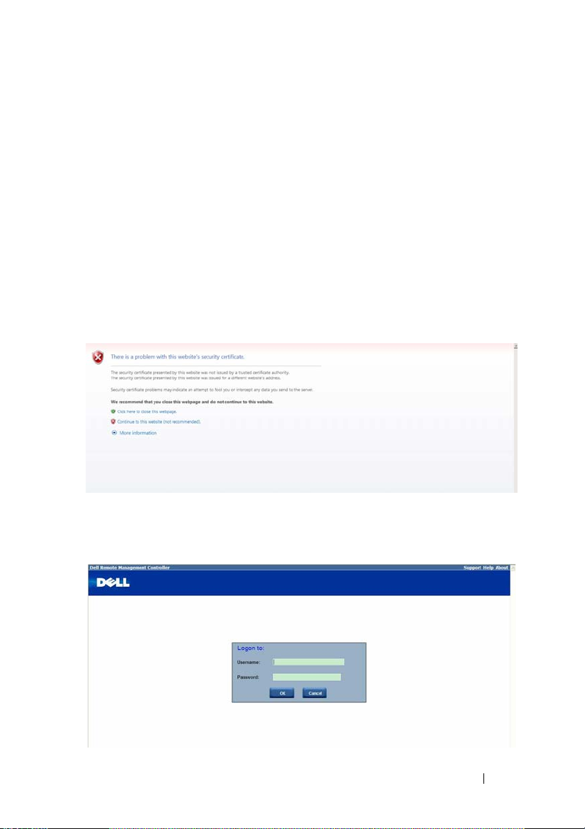
When connecting to the PowerEdge C6220 II using a web browser, Secure
Sockets Layer (SSL) is automatically activated and the display user login form
is displayed prompting for the username and password. This authentication
with SSL protection prevents unauthorized intruders from gaining access to
the PowerEdge C6220 II web server. If authentication is passed, you can
manage the server by privilege.
A security certificate warning displays, choose Continue to this website (not
recommended) to continue.
The user authentication web page is displayed. Enter the default user name
and password, and click OK.
7
Page 8
Guide\Server\Dell\C6220II\BMC\C6220II_BMC_HOM_section1.fm
Table 1-1. Default User Name and Password
Field Default
User Name root
Password root
NOTE: The default username and password are in lowercase characters. It is
advised to change the root password once you have logged in.
FILE LOCATION: D:\Projects\User
Click the Help button on the top right corner for assistance. Click Logout to
exit.
The Remote Management Controller’s web UI is divided into two areas. On
the left is the multi-level navigation menu bar, which is divided into four
categories and each category is subdivided into several submenus. On the
right is the information pane, which displays list of information, commands
or configuration options that are associated with the category selected from
the navigation menu bar.
8
Page 9

Guide\Server\Dell\C6220II\BMC\C6220II_BMC_HOM_section1.fm
FILE LOCATION: D:\Projects\User
Remote Management Controller
The Remote Management Controller menu provides general information
about the server including the BMC firmware and network information.
Administrators and operators can use this menu to check the sled server
health and access all network configuration options. It also provides options
for managing security, user access, session status, updating the BMC
firmware, and performing remote system shutdown or reboot.
The remote management controller menu provides access to the following
configuration options:
• Properties
•Chassis
• Configuration
• Sessions
•Update
• Utilities
9
Page 10
Guide\Server\Dell\C6220II\BMC\C6220II_BMC_HOM_section1.fm
FILE LOCATION: D:\Projects\User
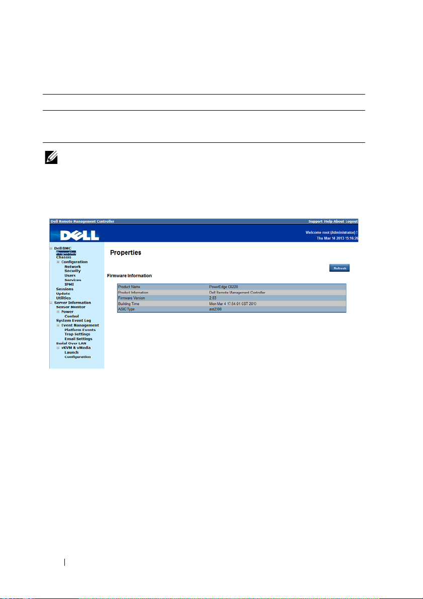
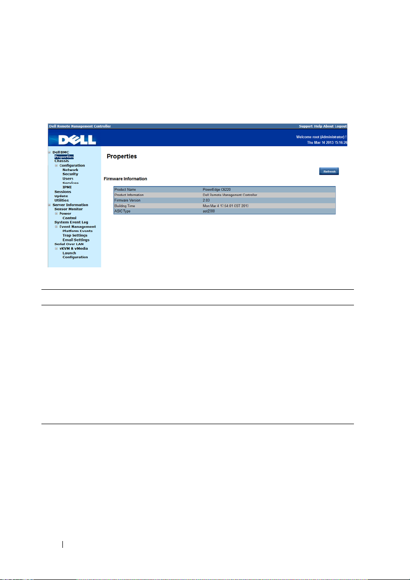
Properties
The Properties option enables you to view the remote sled server BMC
firmware information.
Table 1-2. Firmware Summary
Item Description
Product Name Sled server system board model name
Product Information Remote Management Controller firmware
Firmware Version Remote Management Controller firmware version
Building Time Date the firmware was last flashed in the following
format:
MM DD YYYY HH: MM: SS
ASIC Type Application-specific integrated circuit (ASIC) type
Refresh Button Use this button to refresh the firmware information
10
Page 11
Guide\Server\Dell\C6220II\BMC\C6220II_BMC_HOM_section1.fm
FILE LOCATION: D:\Projects\User
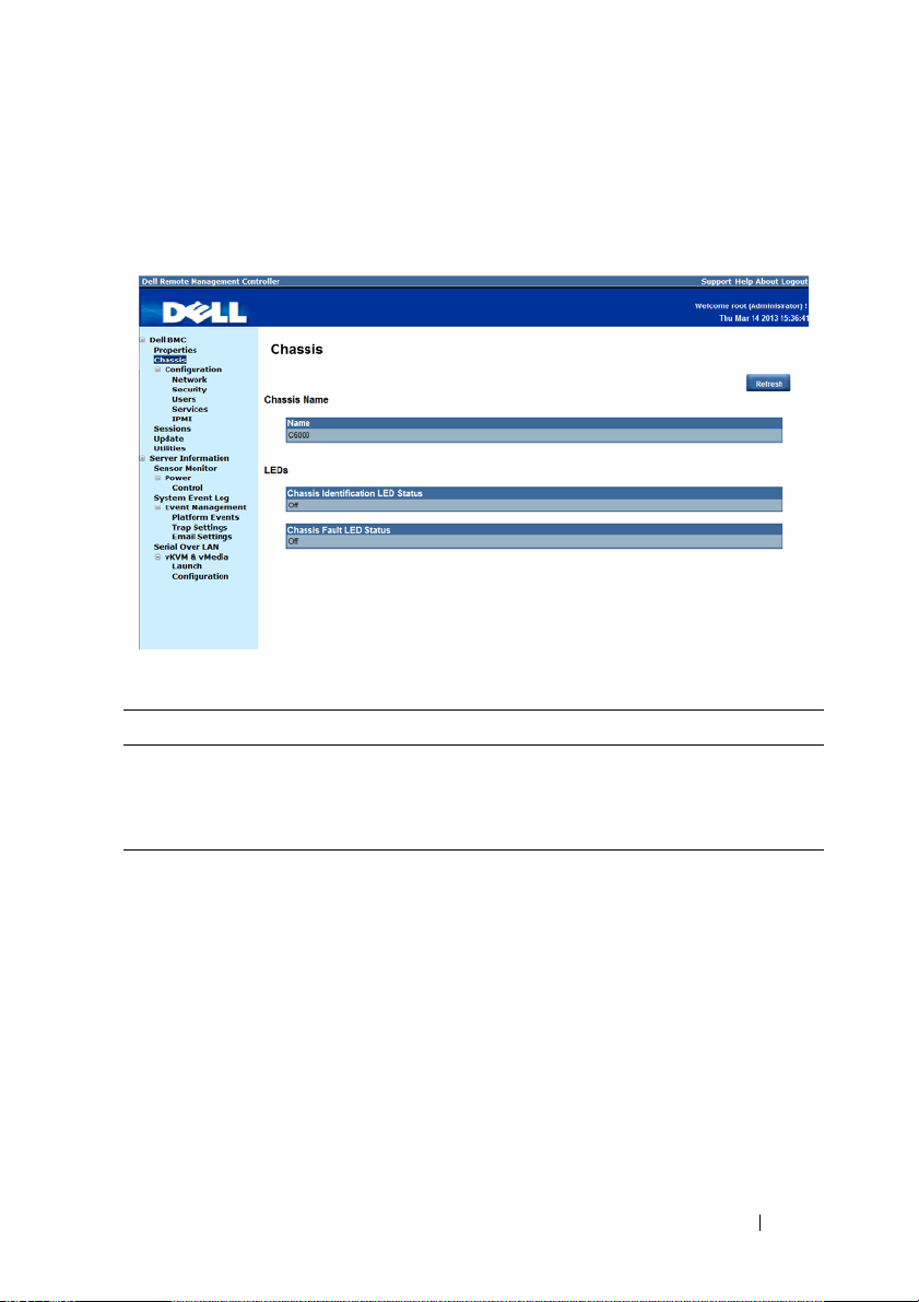
Chassis
The Chassis option enables you to view a summary chassis information
including LEDs and power supply status.
Table 1-3. Chassis Summary
Item Description
Chassis Name Server chassis product model name
LEDs Server chassis identification and fault LED status
Refresh Button Use this button to refresh the chassis information
11
Page 12
Guide\Server\Dell\C6220II\BMC\C6220II_BMC_HOM_section1.fm
FILE LOCATION: D:\Projects\User
Configuration
The Configuration option enables you to view and set values for various
system functions.
Click on the Configuration option to expand the submenu items.
•Network
•Security
•Users
•Services
•IPMI
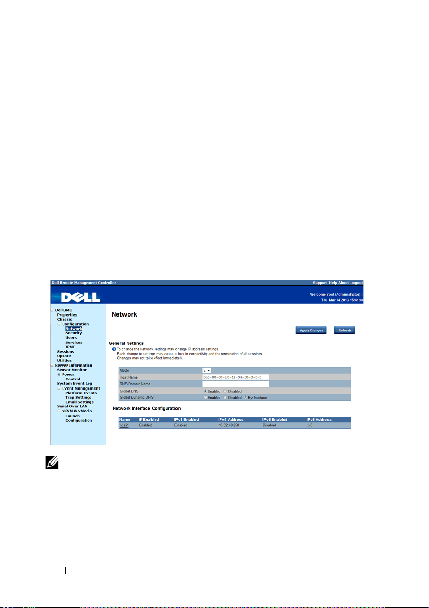
Network
Select the Network submenu to view and configure the network setting
parameters.
NOTE: To change any network setting parameters, you must have permission to
configure the BMC.
12
Page 13

Guide\Server\Dell\C6220II\BMC\C6220II_BMC_HOM_section1.fm
FILE LOCATION: D:\Projects\User
Table 1-4. Network
Item Description
General Settings
Mode Select a network connectivity mode.
Host Name Type the name of the BMC host server in this field.
DNS Domain Name Type the domain name of the DNS server in this field.
Network Interface Configuration
Name Column Indicates the network interface name.
iF Enabled Column Indicates the operational status of the NIC.
IPv4 Enabled Column Indicates the operational status of the Internet Protocol
version 4 (IPv4).
IPv4 Address Column Indicates the IPv4 IP address.
IPv6 Enabled Column Indicates the operational status of the IPv6 protocol.
IPv6 Address Column Indicates the IPv6 IP address.
Apply Changes Button
Refresh Button
Use this button to apply the changes.
Use this button to refresh the network information.
13
Page 14
Guide\Server\Dell\C6220II\BMC\C6220II_BMC_HOM_section1.fm
FILE LOCATION: D:\Projects\User
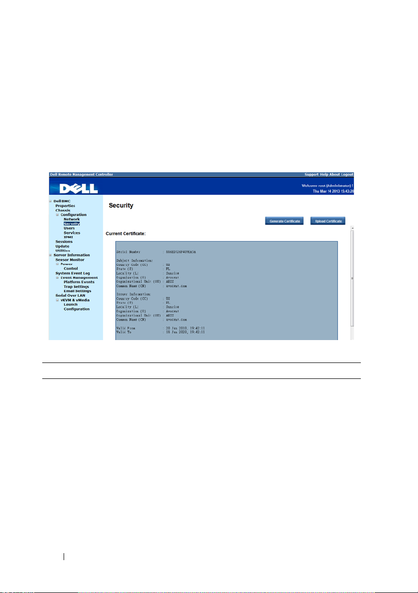
Security
Select the Security submenu to view server certificate information. Secure
server certificates ensure the identity of a remote system and ensure that
information exchanged with the remote system cannot be viewed or changed
by others. Users with administrator or operator privileges can create a
Certificate Signing Request (CSR) and upload the file to a certifying
authority.
Table 1-5. Security
Options Description
Serial Number Server certificate serial number
Subject Information:
Country Code (CC) Name of the country where the entity applying for the
certification is located
State (S) State or province where the entity applying for the
certification is located
Locality (L) City or location of the entity being certified
Organization (O) Legal name of the company or institution
Organizational Unit (OU) Name associated with the organizational unit
Common Name (CN) DNS host name
14
Page 15

Guide\Server\Dell\C6220II\BMC\C6220II_BMC_HOM_section1.fm
FILE LOCATION: D:\Projects\User
Table 1-5. Security
Options Description
Issuer Information:
Country Code (CC) Country that issued the certificate
State (S) State that issued the certificate
Locality (L) City or location that issued the certificate
Organization (O) Name of the institution that issued the certificate
Organizational Unit (OU) Unit that issued the certificate
Common Name (CN) Certification authority
Valid From Server certificate effective date
Valid Until Server certificate expiration date
Generate Certificate
Button
Use this button to create a Certificate Signing Request
(CSR)
Upload Certificate Button Use this button to upload the CSR file to a certifying
authority
15
Page 16
Guide\Server\Dell\C6220II\BMC\C6220II_BMC_HOM_section1.fm
FILE LOCATION: D:\Projects\User
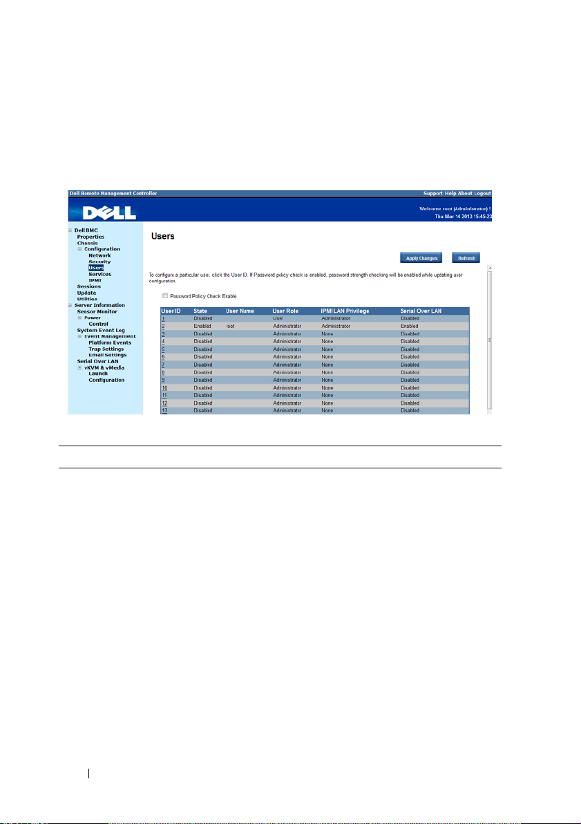
Users
Select the Users submenu to view the list of users authorized to access the
system. Administrators can grant any user permission privileges by clicking a
user ID number.
Table 1-6. Users
Item Description
Password Policy Check
Enable Checkbox
Enables you to improve the security of your passwords
by enforcing strong password security policies.
If enabled, BMC will perform a password check each
time the user configuration is updated. The user
password must have the following requirements:
• Cannot contain the user’s account name or full name.
• Must have a minimum of 8 and a maximum of 14
alphanumeric characters.
• Can contain numbers (0-9), upper and lower case
letters (A-Z, a-z), special characters (for example, !, $,
#, %).
• Can contain a catch-all category of any Unicode
character that does not fall under the previous three
categories. This category can be regionally specific.
• Cannot contain or be similar to the last 5 passwords.
16
Page 17

Guide\Server\Dell\C6220II\BMC\C6220II_BMC_HOM_section1.fm
FILE LOCATION: D:\Projects\User
Table 1-6. Users
Item Description
User ID Column Displays a list of users who can access this BMC
If a privilege is assigned to a user, the user ID appears as
a hyperlink.
State Column Shows the status of each user
User Name Column Shows the login name of the user
User Role Column Shows user defined roles
IPMI LAN Privilege
Displays the IPMI LAN privilege level
Column
IPMI Serial Privilege
Displays the IPMI serial privilege level
Column
Serial Over LAN Column Indicates whether permission for configuring the serial
over LAN connection is enabled or disabled
SOL provides serial access over the NIC interface. The
server’s integrated BMC redirects data information from
the serial port (UART), and packs the data and transfers
the UART data to the NIC interface.
Apply Changes Button Use this button to apply the changes
Refresh Button Use this button to refresh the user list
17
Page 18
Guide\Server\Dell\C6220II\BMC\C6220II_BMC_HOM_section1.fm
FILE LOCATION: D:\Projects\User
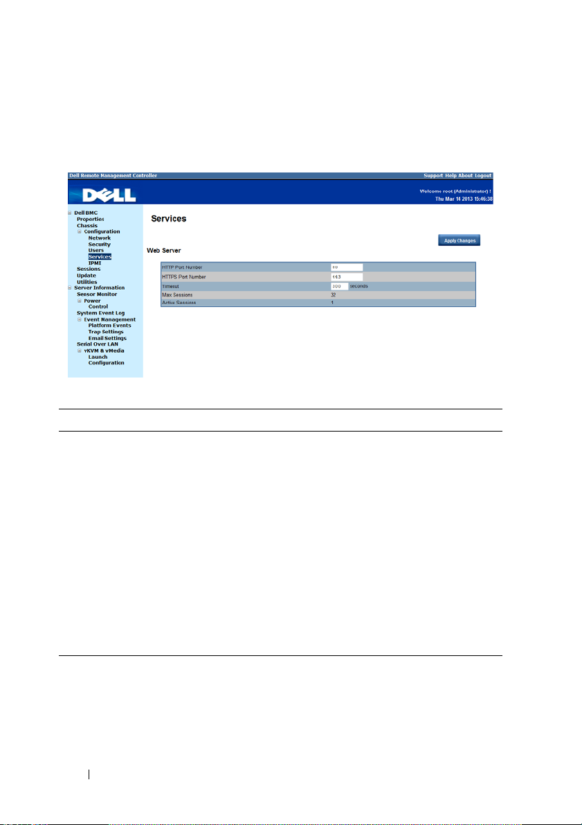
Services
Select the Services submenu to view the communication service parameters.
Users with administrator or operator privileges can set up this service.
Table 1-7. Services
Item Description
HTTP Port Number Port to use for HTTP-based communication. The
default HTTP port number is 80.
HTTPS Port Number Port to use for HTTPS-based communication. The
default HTTPS port number is 443.
Timeout Specify the timeout value. The timeout value can range
from 60 to 10800 seconds.
Max Sessions Indicates the number of simultaneous sessions allowed
for the system.
Active Sessions Indicates the number of sessions currently running on
the system.
Apply Changes Button Use this button to apply the changes and restart the web
server.
18
Page 19

Guide\Server\Dell\C6220II\BMC\C6220II_BMC_HOM_section1.fm
FILE LOCATION: D:\Projects\User
IPMI
Select the IPMI submenu to view the IPMI-based communication service
parameters. Users with administrator or operator privileges can configure the
IPMI settings.
Table 1-8. IPMI
Item Description
IPMI Settings
Enable IPMI Over LAN
Channel Privilege Level
Limit
Encryption Key
Enables or disables IPMI over LAN access.
Select a user privilege level for IPMI over LAN access.
Type the IPMI LAN channel encryption key.
NOTE: The encryption key must consist of an even
number of hexadecimal characters with a maximum of 20
ASCII hex pairs with no spaces between the pairs.
Apply Changes Button
Use this button to apply the changes.
19
Page 20

Guide\Server\Dell\C6220II\BMC\C6220II_BMC_HOM_section1.fm
FILE LOCATION: D:\Projects\User
Sessions
The Sessions option enables you to view sessions currently running on the
system.
Table 1-9. Sessions
Item Description
Session ID Column Shows the number of active sessions or session ID
numbers.
User Name Column Shows the login name of the user.
IP Address Column Shows the IP address of the user.
Session Type Column Indicates media session type — Virtual KVM, Virtual
Media, or GUI.
Kill This column includes a Trash icon that enables users
with administrator or operator privilege to end an
associated session.
Refresh Button Use this button to refresh the session information.
20
Page 21

Guide\Server\Dell\C6220II\BMC\C6220II_BMC_HOM_section1.fm
FILE LOCATION: D:\Projects\User
Update
The Update option enables users with administrator or operator privileges to
update the sled server’s BMC firmware. The following data is included in the
BMC firmware package:
• Compiled BMC firmware code and data
• Web-based user interface, JPEG, and other user interface data files
• Default configuration files
NOTE: The firmware update retains the current BMC settings.
Table 1-10. Update
Item Description
Firmware Type Select the firmware type (BMC/BIOS/FC) that you
want to upgrade.
NOTE: If a fan controller board (FCB) firmware update
type is selected, the sled(s) in the server chassis that are
not performing the update request or action will consider
the FCB firmware offline after 10 seconds.
File Path Enter the complete path and file name for the firmware
file.
21
Page 22

Guide\Server\Dell\C6220II\BMC\C6220II_BMC_HOM_section1.fm
Table 1-10. Update
Item Description
Browse Button Use this button to navigate to the firmware file saved
Update Type Select a firmware update type.
FILE LOCATION: D:\Projects\User
onto a media.
• Normal (default): Updates the firmware only when the
BMC validates the target board, target product, and
version number.
• Forced: This forces the BMC to update the image
without first validating the target board, target product
and version number.
CAUTION: Do not attempt a forced firmware upgrade
without assistance from Dell Technical Support.
Upload Button Use this button to initialize the update process.
Updating the BMC Firmware
CAUTION: Before beginning the firmware update, download the latest firmware
version and save it on your local system. During the process of a firmware update,
the AC power of the managed system should not be unplugged and the Web GUI
should not be closed.
NOTE: You will not be able to perform any task during the firmware upgrade
process. Wait for the upgrade to be completed before attempting any task.
1
Click the
2
Click
Update
Browse
menu to access the Firmware Update page.
to locate the firmware file. Or, enter the path on your system
where the firmware image file resides. For example:
C:\Updates\V1.0\<image_name>
3
Select firmware update type. If a BMC firmware update type is selected,
after the upload process is started, any attempt to refresh, logout or
navigate away from the update page will restart the remote system.
When you choose to force a firmware update, BMC will update the image
without first validating the target board, target product and version
number.
4
Click
Upload
NOTE: The upload process terminates all other sessions including KVM.
to initialize the update process.
22
Page 23

FILE LOCATION: D:\Projects\User
5
Guide\Server\Dell\C6220II\BMC\C6220II_BMC_HOM_section1.fm
Click
Updat
e. When the update is completed, the remote system will
reboots automatically.
NOTE: When the firmware update is in process, the system will not be available to
other users.
Utilities
The Utilities option enables users with administrator and operator privileges
to remotely reboot or reset the BMC firmware.
Table 1-11. Utilities
Item Description
Reboot Button Use this button to remotely reboot this BMC firmware.
Factory Default Button Use this button to reset the BMC configuration values
back to default values.
CAUTION: This will reset all BMC settings back to
default setting.
23
Page 24

Guide\Server\Dell\C6220II\BMC\C6220II_BMC_HOM_section1.fm
FILE LOCATION: D:\Projects\User
Server Information
The Server Information menu enables users with administrator and operator
privileges to remotely perform a power control operation on the server.
The Server Information menu provides access to the following configuration
options.
• Sensor Monitor
•Power
Sensor Monitor
The Sensor Monitor option enables users with administrator and operator
privileges to remotely monitor the server’s voltage, power supplies, batteries,
fan sensors and temperature sensors.
If the server power is off, the following message appears on the screen:
The System is powered off. Unable to retrieve the sensor
information.
NOTE: Remote Management Controller does not store configuration settings in the
Sensor Monitor page.
24
Page 25

Guide\Server\Dell\C6220II\BMC\C6220II_BMC_HOM_section1.fm
Table 1-12. Sensor Monitor
Item Description
General Settings
Auto Refresh Interval Select a time interval (Never Auto-Refresh, Every 1
Sensor Type Select a sensor type.
Display Type Select the sensor display type.
Refresh Button
FILE LOCATION: D:\Projects\User
Minute, Evert 5 Minutes) to automatically reload the page.
•Voltages
•Power supplies
• Batteries
•Fans
•Temperatures
• All sensors
•Active sensors
Use this button to refresh the session information.
Voltages
Select Vo lt ag es from the Sensor Type drop-down menu to view server’s
voltage sensor readings data as well as event log items. For more information
on voltage threshold settings and the conversion equation for the voltage
readings, see "Threshold Settings and Converting Formulas" on page 60.
25
Page 26

Guide\Server\Dell\C6220II\BMC\C6220II_BMC_HOM_section1.fm
FILE LOCATION: D:\Projects\User
Table 1-13. Voltages Sensor Readings
Items Description
General Settings For more information on this option, see Table 1-12.
Probe List
Status Column
Probe Name Column
Indicates the voltage sensor status.
Shows the name of the voltage sensor.
Typical voltage probes:
• 12 V standby
•5 V standby
•5 V
• 3.3 V standby
• 3.3 V
NOTE: The 5 V and 3 V sensors are unavailable when
powered off.
Reading Column
Lower Non-Recoverable
Column
Lower Critical Column
Lower Non-Critical
Column
Upper Non-Critical
Column
Upper Critical Column
Upper Non-Recoverable
Column
Refresh Button
Shows the voltage sensor reading.
Shows the system board lower non-recoverable threshold
voltage.
Shows the system board lower critical threshold.
Shows the system board lower non-critical threshold.
Shows the system board upper non-critical threshold.
Shows the system board upper critical threshold.
Shows the system board upper non-recoverable
threshold.
Use this button to refresh the voltage information.
26
Page 27

Guide\Server\Dell\C6220II\BMC\C6220II_BMC_HOM_section1.fm
FILE LOCATION: D:\Projects\User
Power Supplies
Select Power Supplies from the Sensor Type drop-down menu to view the
status of the server chassis’s power supply. The power supplies are shared
among all the sled servers in the server chassis. Click the Chassis option on
the menu bar to view detailed information about the server chassis power
supply.
Table 1-14. Power Supplies Sensor Readings
Item Description
General Settings For more information on this option, see Table 1-12.
Power Supplies Status
NOTE: The sled server does not have its own power supply, power is supplied by the
server chassis. The Power Supplies Status table appears as blank. To view detailed
information about the server chassis power supply, see "Chassis" on page 11.
Status Column
Probe Name Column
Description Column
Power Supplies Information
Location Column
Status Column
Shows the power supply status.
Shows the name of the power supply sensor.
Shows the presence of power supply module.
Shows the location of the power supply module.
Shows the status of the power supply.
27
Page 28

Guide\Server\Dell\C6220II\BMC\C6220II_BMC_HOM_section1.fm
Table 1-14. Power Supplies Sensor Readings
Item Description
Input Wattage Column
Maximum Wattage Column
Firmware Version Column
Refresh Button
FILE LOCATION: D:\Projects\User
Shows the power supply peak watt.
Shows the power supply maximum watt.
Shows the firmware version.
Use this button to refresh the power supply
information.
Batteries
Select Batteries from the Sensor Type drop-down menu to view the status of
the server system board battery.
Table 1-15. Batteries Sensor Readings
Item Description
General Settings For more information on this option, see Table 1-12.
Probe List
Status Column
Probe Name Column
Shows the system board CMOS coin-cell battery status.
Shows the name of the battery sensor.
28
Page 29

Guide\Server\Dell\C6220II\BMC\C6220II_BMC_HOM_section1.fm
Table 1-15. Batteries Sensor Readings
Item Description
Reading Column
Refresh Button
FILE LOCATION: D:\Projects\User
Shows the battery sensor reading.
Use this button to refresh the battery information.
Fans
Select Fans from the Sensor Type drop-down menu to view the status and
readings of the server fan sensors.
Table 1-16. Fans Sensor Readings
Items Description
General Settings For more information on this option, see Table 1-12.
Probe List
Status Column
Probe Name Column
Reading Column
Lower Non-Recoverable
Column
Shows fan sensor status
Shows the fan sensor number.
Shows the fan sensor revolutions per minute (RPM)
reading.
Shows the fan lower non-recoverable threshold.
29
Page 30

Guide\Server\Dell\C6220II\BMC\C6220II_BMC_HOM_section1.fm
Table 1-16. Fans Sensor Readings
Items Description
Lower Critical Column
Lower Non-Critical
Column
Upper Non-Critical
Column
Upper Critical Column
Upper Non-Recoverable
Column
Redundancy Status
Status Column
Probe Name Column
Description Column
Refresh Button
FILE LOCATION: D:\Projects\User
Shows the fan lower critical threshold.
Shows the fan lower non-critical threshold.
Shows the fan upper non-critical threshold.
Shows the fan upper critical threshold.
Shows the fan upper non-recoverable threshold.
Shows the fan sensor status.
Shows the fan sensor number.
Shows the presence of fan module.
Use this button to refresh the fan sensor reading.
Temperatures
Select Temperatures from the Sensor Type drop-down menu to view the
status and readings of the server temperature sensors. For more information
on temperature threshold settings and the conversion equation for the
temperature readings, see "Threshold Settings and Converting Formulas" on
page 60.
30
Page 31

Guide\Server\Dell\C6220II\BMC\C6220II_BMC_HOM_section1.fm
FILE LOCATION: D:\Projects\User
Table 1-17. Temperature Sensor Readings
Items Description
General Settings For more information on this option, see Table 1-12.
Probe List
Status Column
Probe Name Column
Displays the status of the temperature sensor.
Displays the temperature sensor name.
Typical temperature probes:
•MEZZ1 Temp
•CPU1 Temp
•CPU2 Temp
• DIMM ZONE 1 Temp
• DIMM ZONE 2 Temp
•PCH Temp
•Inlet Ambient Temp
Reading Column
Lower Non-Recoverable
Column
Lower Critical Column
Lower Non-Critical
Column
Upper Non-Critical
Column
Upper Critical Column
Displays the temperature sensor reading.
Displays the temperature sensor lower non-recoverable
threshold.
Displays the temperature sensor lower critical threshold.
Displays the temperature sensor lower non-critical
threshold.
Displays the temperature sensor upper non-critical
threshold.
Displays the temperature sensor upper critical
threshold.
Upper Non-Recoverable
Column
Refresh Button
Displays the temperature sensor upper non-recoverable
threshold.
Use this button to refresh the temperature sensor
reading.
31
Page 32

Guide\Server\Dell\C6220II\BMC\C6220II_BMC_HOM_section1.fm
FILE LOCATION: D:\Projects\User
Power
The Power option enables you to view the server’s power status. Click on the
Power option to view the Control submenu.
Control
The Control submenu lets you view the server’s power status. Users with
administrator and operator privilege can perform a power control operation
on the server.
Table 1-18. Power Control
Item Description
Power S tatus
Power Status Displays the server power status.
Power Control Operations
Power On System Option Select this option to power up the server.
Power Off System Option Select this option to perform an immediate
shutdown of the server.
Power Cycle System Option Select this option to perform a graceful shutdown
before power to the sled is turned off.
Hard Reset (Restart) Select this option to remotely reset the server without
powering off (warm boot).
Apply Changes Button
Use this button to apply the changes.
32
Page 33

Guide\Server\Dell\C6220II\BMC\C6220II_BMC_HOM_section1.fm
FILE LOCATION: D:\Projects\User
System Event Log
The System Event Log menu enables users with administrator and operator
privileges to view system event information such as event ID, time stamp,
sensor name, sensor type, and description (Event Log button).
Table 1-19. System Event Log
Items Description
Severity Column Indicates the severity level of the log entry.
• Normal event
• Non-critical event
• Critical event
Date/Time Column Displays the date and time the event occurred. If the
system time is not set or is undetermined, the time will
show as [System Boot]. Events are listed in order of their
occurrence.
Description Column This column shows a brief description of the event.
Clear Log Button Use this button to clear the event logs.
33
Page 34

Guide\Server\Dell\C6220II\BMC\C6220II_BMC_HOM_section1.fm
Table 1-19. System Event Log
Items Description
Save Log Button Use this button to save system event logs.
Refresh Button Use this button to refresh the system event log.
FILE LOCATION: D:\Projects\User
Event Management
The Event Management option enables users with administrator or operator
privilege to configure the Platform Event Filter (PEF) filters, SNMP trap
settings, and email notifications.
Click on the Event Management option to expand the submenu items.
• Platform Events
• Trap Settings
• Email Settings
Platform Events
Select the Platform Events submenu to configure the PEF parameters and
alert destinations.
34
Page 35

Guide\Server\Dell\C6220II\BMC\C6220II_BMC_HOM_section1.fm
FILE LOCATION: D:\Projects\User
Table 1-20. Platform Event Filters
Items Description
Platform Event Filters (PEF) Action Global Control List
Action Name
Specify a PEF action with the occurrence of a specific
event.
•Reboot
• Power Cycle
•Power Off
• Generate PET
Platform Event Filters (PEF) List
Global Alerting Enable
Filter Name Column
Select to enable all PEF and email notification alerts.
This column lists the platform event filters.
• Fan Critical Assert filter
• Battery Warning Assert filter
• Battery Critical Assert filter
• Discrete Voltage Critical Assert filter
• Temperature Warning Assert filter
• Temperature Critical Assert filter
• Intrusion Critical Assert filter
• Redundancy Degraded filter
• Redundancy Lost filter
• Processor Warning Assert filter
• Processor Critical Assert filter
• Processor Absent filter
You can specify the following action(s) to be taken in
response to a PEF.
•None
•Reboot
•Power Cycle
•Power Off
• Generate
Platform Event Trap (PET)
35
Page 36

Guide\Server\Dell\C6220II\BMC\C6220II_BMC_HOM_section1.fm
Table 1-20. Platform Event Filters
Items Description
Apply Changes Button
NOTE: BMC event log “Processor #0x1c” or “Processor #0x1d” clarification:
This event is generated from Intel CPU ME (Management Engine). There are two
factors that can cause this event to be triggered, one cause is the processor is hot
and the second cause is the system board has received a power throttling signal
from the chassis controller. You can check the throttling settings if you do not want
to do power throttling.
FILE LOCATION: D:\Projects\User
Use this button to apply the changes.
Trap Settings
Select the Trap S et ti n gs submenu to view and manage the Simple Network
Management Protocol (SNMP) trap events.
Table 1-21. Trap Settings
Items Description
IPv4 Destination List
Enable Checkbox Enables or disables an IPv4 destination address. You can
enable up to four IPv4 destination addresses.
IPv4 Address Configure up to four IPv4 addresses.
36
Page 37

Guide\Server\Dell\C6220II\BMC\C6220II_BMC_HOM_section1.fm
Table 1-21. Trap Settings
Items Description
Send Test Trap Button Use this button to send a test trap to a corresponding
IPv6 Destination List
Enable Checkbox Enables or disables an IPv6 destination address. You can
IPv6 Address Configure up to four IPv6 addresses.
Send Test Trap Button Use this button to send a test trap to a corresponding
Community String
Community Name View or modify the SNMP community name.
Apply Changes Button Use this button to apply the changes.
FILE LOCATION: D:\Projects\User
email address.
enable up to four IPv6 destination addresses.
email address.
Email Settings
Select the Email Settings submenu to view email settings. Users with
administrator or operator privileges can set email addresses for sending alert
notifications.
37
Page 38

Guide\Server\Dell\C6220II\BMC\C6220II_BMC_HOM_section1.fm
FILE LOCATION: D:\Projects\User
Table 1-22. Email Settings
Items Description
Sender Information
From
Specifies the sender’s address.
The sender’s address must have the following
requirements:
• Can contain a combination of the following
characters:
• Upper and lowercase letters (A-Z, a-z)
•Numbers (0-9)
• Special characters (for example, /, =, -, _, +, !, #,
$, %, etc.).
• Cannot consist of only blank spaces
If you leave this field empty, then BMC will fill in the
sender address automatically. The sender address may
appear as <hostname>@<domain name>.
Destination Email Addresses
Enable Checkbox
Enables or disables an email alert notification. You can
enable up to four email alert notifications.
Destination Email Address
Assign the email address that will receive the alert
messages.
Email Description
Enter a short description for the email alert
notification.
Send Alert Button
Use this button to send an email alert to a
corresponding email address.
SMTP (Email) Server Address
SMTP IP Address
Specify the IP address of the SMTP mail server.
SMTP Authentication
Enable Checkbox
Enables or disables the SMTP authentication for the
mail server.
Username
Pas sword
Specifies a username for an authenticated sendmail.
Specifies a password for an authenticated sendmail.
38
Page 39

Guide\Server\Dell\C6220II\BMC\C6220II_BMC_HOM_section1.fm
FILE LOCATION: D:\Projects\User
Table 1-22. Email Settings
Items Description
STARTTLS mode
Select a Start Transport Layer Security (StartTLS)
mode.
SASL Mode
Select a Simple Authentication and Security Layer
(SASL) authentication mode.
Apply Changes Button
Use this button to apply the changes.
39
Page 40

Guide\Server\Dell\C6220II\BMC\C6220II_BMC_HOM_section1.fm
FILE LOCATION: D:\Projects\User
Serial Over LAN
The Serial over LAN menu enables users with administrator and operator
privileges to configure the Serial over LAN settings, select or change pertinent
values for each attribute and save any changes.
Table 1-23. Serial Over LAN Settings
Items Description
Enable Serial Over LAN
Checkbox
Baud Rate Select the IPMI SOL baud rate.
Channel Privilege Level
Limit
Apply Changes Button Use this button to apply the changes.
Enables or disables Serial over LAN (SOL) connection.
• 19.2 kbps
• 38.4 kbps
• 57.6 kbps
• 115.2 kbps
Specify a privilege level on the LAN channel.
40
Page 41

Guide\Server\Dell\C6220II\BMC\C6220II_BMC_HOM_section1.fm
FILE LOCATION: D:\Projects\User
vKVM & vMedia
The vKVM & vMedia option enables the administrators to view and
configure the virtual KVM and media settings and launch the Java KVM and
VM console clients.
Click on the vKVM & vMedia option to expand the submenu items.
• Launch
• Configuration
Launch
Select the Launch submenu to view and initiate console redirection.
Table 1-24. Virtual KVM and Media Launch Settings
Items Description
Virtual KVM Configuration
Enabled
Max Sessions
Active Sessions
Remote Port
KVM status
Maximum number of console redirection sessions
allowed
Number of active console sessions
Network port number used for connecting to the KVM
client
41
Page 42

Guide\Server\Dell\C6220II\BMC\C6220II_BMC_HOM_section1.fm
Table 1-24. Virtual KVM and Media Launch Settings
Items Description
Video Encryption
Enabled
Preferred Client Type
Virtual Media Configuration
Max Sessions
Active Sessions
Encryption Enabled
Preferred Client Type
Launch Java KVM Client
Button
Launch Java VM Client
FILE LOCATION: D:\Projects\User
Video encryption status
Client application used for connecting to the KVM
client
Maximum number of console redirection sessions
allowed
Number of active console sessions
Video encryption status
Client application used for connecting to the VM client
Use this button to launch the Java-based KVM client
Use this button to launch the Java-based VM client
Console Redirection
The most powerful feature of the Remote Management Controller is the
ability to redirect the host system’s console, managing the host system as
though it were physically in front of you. Note the following about console
redirection:
• You can run a maximum of four simultaneous redirection sessions.
• The Java® Video Viewer (version 1.5.15 or later) is required to run the
console redirection. If the BMC detects that the video viewer is not
installed, you are prompted to install it.
• The recommended display resolution on the management station is at
least 1280 x 1024 pixels at 60 Hz with 32 bit color. If the resolution does
not meet this minimum, you will be unable to view the console in full
screen mode.
• Before using console redirection, verify that the virtual KVM and Media
features are enabled. See "Configuration" on page 43".
• Console redirection remains active even after web session timeout.
42
Page 43

Guide\Server\Dell\C6220II\BMC\C6220II_BMC_HOM_section1.fm
FILE LOCATION: D:\Projects\User
To start a remote console session from the Virtual KVM and Media Launch
window, click the Launch Java KVM Client or Launch Java VM Client
button. This launches the redirection console via the JViewer Java applet. For
further information on remote console sessions, see "Using the Video Viewer"
on page 45.
Configuration
Select the Configuration submenu to configure the virtual KVM and virtual
media.
Table 1-25. Virtual KVM and Media Configuration
Items Description
Virtual KVM Configuration
Enabled
Max Sessions
Remote Port
Video Encryption
Enabled
Enables or disables the virtual KVM.
Sets the maximum number of console redirection
sessions allowed
Select the network port number for connecting to the
KVM client.
If enabled, the server encrypts all video data prior to
transporting to the KVM.
43
Page 44

Guide\Server\Dell\C6220II\BMC\C6220II_BMC_HOM_section1.fm
FILE LOCATION: D:\Projects\User
Table 1-25. Virtual KVM and Media Configuration
Items Description
Preferred Client Type
Select a client application to use for connecting to the
KVM client.
Virtual Media Configuration
Enabled
Encryption Enabled
Preferred Client Type
Enables or disables the virtual media.
Enables or disables the virtual media encryption.
Select a client application to use for connecting to the
VM client.
44
Page 45

Guide\Server\Dell\C6220II\BMC\C6220II_BMC_HOM_section1.fm
FILE LOCATION: D:\Projects\User
Using the Video Viewer
The Video Viewer provides a user interface between the management station
and the managed server, allowing you to see the managed server's desktop and
control its mouse and keyboard functions from your management station.
When you connect to the remote system, the Video Viewer login screen
prompts for the password.
The Video Viewer provides various control adjustments such as snapshots,
keyboard macros, mouse synchronization, power actions, and access to Virtual
Media. Click the Help menu for more information on these functions.
When you start a console redirection session and the Video Viewer appears,
you may need to adjust the video color mode and synchronize the mouse
pointers.
45
Page 46

Guide\Server\Dell\C6220II\BMC\C6220II_BMC_HOM_section1.fm
• Ctrl+Alt+Del • Alt+Tab
•Alt+Esc •Ctrl+Esc
• Alt+Space • Alt+Enter
• Alt+Hyphen • Alt+F4
• PrtScrn • Alt+PrtScrn
•F1 •Pause
• Tab • Ctrl+Enter
• Alt+SysRq • Alt+L Shift-RShift-Esc
• Ctrl-Alt-Backspace
FILE LOCATION: D:\Projects\User
Video Viewer Menu
The Video Viewer menu provides access to additional functions, outlined in
the following tables.
Table 1-26. File Menu Items
Menu Option Description
Capture to
Clipboard
Exit Closes the Video Viewer window.
Table 1-27. View Menu Items
Menu Option Description
Hide Status Bar Hides or displays the status bar.
Refresh Redraws the viewer screen image.
Full Screen Displays the Video Viewer menu in full screen mode.
Fit Resizes the Video Viewer menu to fit whole monitor screen.
Captures the current remote system screen to save it to the
clipboard.
Table 1-28. Macros Menu Items
Menu Option Description
User Defined
Macros
46
Select a pre-defined command or add your own user-defined
commands to send to the server. The Macros menu provides
the following keyboard macros:
Page 47

Guide\Server\Dell\C6220II\BMC\C6220II_BMC_HOM_section1.fm
FILE LOCATION: D:\Projects\User
Table 1-29. Tools Menu Items
Menu Option Description
Sessions Options Provides additional session viewer control adjustments.
The General tab allows you to enable the keyboard pass
through mode feature. Select Pass all keystrokes to target
to pass your management station's keystrokes to the
remote system.
The Mouse tab enables you to select the operating
system you are using to optimize console redirection
mouse performance.
The Video Quality tab provides video adjustments that
allow you to optimize the video for the best possible view.
Session User List Lists the users in the management console.
Single Cursor Enables or disables the single cursor mode.
If this function is disabled, the local and remote
operating system will use different mouse accelerating
algorithms, which results in offset between the local and
remote mouse cursors.
Stats Displays the performance statistics of the console
redirection session.
Table 1-30. Power Menu Items
Menu Option Description
Power On System Powers on the server.
Power Off System Powers off the server.
Graceful Shutdown Shuts down the server.
Reset System (warm boot) Reboots the server without powering it off.
Power Cycle System
Powers off and then reboots the server.
(cold boot)
47
Page 48

Guide\Server\Dell\C6220II\BMC\C6220II_BMC_HOM_section1.fm
FILE LOCATION: D:\Projects\User
Table 1-31. Help Menu Items
Menu Option Description
Contents and Index Opens the Video Viewer Help.
About Displays the Video Viewer version information.
48
Page 49

Guide\Server\Dell\C6220II\BMC\C6220II_BMC_HOM_section1.fm
FILE LOCATION: D:\Projects\User
IPMI 1.5/2.0 Command Support List
The IPMItool program provides a simple command-line interface for
managing IPMI-enabled devices. The IPMItool enables you to read the BMC
devices, BMC watchdog timer, PEF/PET alerts, SDR, events, SEL, FRU
information, serial/modem devices, set LAN configuration parameters,
update the BMC firmware remotely and perform remote server chassis or sled
server power control.
NOTE: For more information about the standard IPMI tool commands, see
ipmitool.sourceforge.net/manpage.html.
The following tables include all commands defined in the IPMI v2.0
specifications. All mandatory commands and some optional functions are
supported. Special functions beyond the scope of IPMI v2.0 are implemented
as original equipment manufacturer (OEM) commands.
In the O/M column:
• M = Mandatory in the IPMI spec and is implemented.
• O = Optional command supported in this implementation.
• N = Not supported in this implementation.
See the Deployment Toolkit Version 1.3 User's Guide for additional
information about installing and using the DTK utilities, and the
Deployment Toolkit Version 1.3 Command Line Interface Reference Guide
for a complete list of all valid options, suboptions, and arguments for using
the BMCCFG.EXE to configure and manage your BMC.
NOTE: For a complete list of all valid options, requirements, and commands refer to
the BMC Firmware Requirements for DCS/PE-C 1.02 documentation.
49
Page 50

Guide\Server\Dell\C6220II\BMC\C6220II_BMC_HOM_section1.fm
FILE LOCATION: D:\Projects\User
Table 1-32. IPMI Device Global Commands (NetFn: 0x06H)
Command NetFn CMD O/M Supported
Get Device ID App 01h M Yes
Broadcast Get Device ID App 02h M Yes
Cold Reset App 03h O Yes
Warm Reset App 04h O No
Get Self Test Results App 05h M Yes
Manufacture Test On App 06h O Yes
Get ACPI Power State App 07h O Yes
Get Device GUID App 08h O Yes
Get NetFn Support App 09h O Yes
Get Command Support App 0Ah O Yes
Get Command Sub-function Support App 0Bh O Yes
Get Configurable Commands App 0C O Yes
Get Configurable Command Sub-functions App 0Dh O Yes
Set Command Enables App 60h O Yes
Get Command Enables App 61h O Yes
Set Command Sub-function Enables App 62h O Yes
Get Command Sub-function Enables App 63h O Yes
Get OEM NetFn IANA Support App 64h O Yes
50
Page 51

Guide\Server\Dell\C6220II\BMC\C6220II_BMC_HOM_section1.fm
FILE LOCATION: D:\Projects\User
Table 1-33. BMC Device and Messaging Commands (NetFn: 0x06H)
Command NetFn CMD O/M Supported
Set BMC Global Enables App 2Eh M Yes
Get BMC Global Enables App 2Fh M Yes
Clear Message Buffer Flags App 30h M Yes
Get Message Buffer Flags App 31h M Yes
Enable Message Channel Receive App 32h O Yes
Get Message App 33h M Yes
Send Message App 34h M Yes
Read Event Message Buffer App 35h O Yes
Get BT Interface Capabilities App 36h M No
Get System GUID App 37h M Yes
Set System Info Parameters App 58h O Yes
Get System Info Parameters App 59h O Yes
Get Channel Authentication Capabilities App 38h O Yes
Get Session Challenge App 39h O Yes
Activate Session Command App 3Ah O Yes
Set Session Privilege Level Command App 3Bh O Yes
Close Session App 3Ch O Yes
Get Session Information App 3Dh O Yes
Get Authentication Code Command App 3Fh O Yes
Set Channel Access Commands App 40h O Yes
Get Channel Access Commands App 41h O Yes
Get Channel Info Command App 42h O Yes
Set User Access Commands App 43h O Yes
Get User Access Commands App 44h O Yes
Set User Name Commands App 45h O Yes
Get User Name Commands App 46h O Yes
51
Page 52

Guide\Server\Dell\C6220II\BMC\C6220II_BMC_HOM_section1.fm
FILE LOCATION: D:\Projects\User
Table 1-34. BMC Device and Messaging Commands (NetFn: 06H)
(continued)
Command NetFn CMD O/M Supported
Set User Password Commands App 47h O Yes
Active Payload Command App 48h O Yes
Deactivate Payload Command App 49h O Yes
Get Payload Activation Status App 4Ah O Yes
Get Payload Instance Info Command App 4Bh O Yes
Set User Payload Access App 4Ch O Yes
Get User Payload Access App 4Dh O Yes
Get Channel Payload Support App 4Eh O Yes
Get Channel Payload Version App 4Fh O Yes
Get Channel OEM Payload Info App 50h O Yes
Master Write-Read I2C App 52h M Yes
Get Channel Cipher Suites App 54h O Yes
Suspend/Resume Payload Encryption App 55h O Yes
Set Channel Security Keys App 56h O Yes
Get System Interface Capabilities App 57h O No
Table 1-35. BMC Watchdog Timer Commands (NetFn: 06H)
Command NetFn CMD O/M Supported
Reset Watchdog Timer App 22h M Yes
Set Watchdog Timer App 24h M Yes
Get Watchdog Timer App 25h M Yes
52
Page 53

Guide\Server\Dell\C6220II\BMC\C6220II_BMC_HOM_section1.fm
FILE LOCATION: D:\Projects\User
Table 1-36. Chassis Device Commands (NetFn: 00H)
Command NetFn CMD O/M Supported
Get Chassis Capabilities Chassis 00h M Yes
Get Chassis Status Chassis 01h M Yes
Chassis Control Chassis 02h M Yes
Chassis Reset Chassis 03h O No
Chassis Identify Chassis 04h O Yes
Set Chassis Capabilities Chassis 05h O Yes
Set Power Restore Policy Chassis 06h O Yes
Get System Restart Cause Chassis 07h O Yes
Set System Boot Options Chassis 08h O Yes
Get System Boot Options Chassis 09h O Yes
Set Front Panel Button Enable Chassis 0Ah O No
Set Power Cycle Interval Chassis 0Bh O Yes
Get POH Counter Chassis 0Fh O No
Table 1-37. PEF/PET Alerting Commands (NetFn: 04H)
Command NetFn CMD O/M Supported
Get PEF Capabilities S/E 10h M Yes
Arm PEF Postpone Timer S/E 11h M Yes
Set PEF Configuration Parameters S/E 12h M Yes
Get PEF Configuration Parameters S/E 13h M Yes
Set Last Processed Event ID S/E 14h M Yes
Get Last Processed Event ID S/E 15h M Yes
Alert Immediate S/E 16h O Yes
PET Acknowledge S/E 17h O Yes
53
Page 54

Guide\Server\Dell\C6220II\BMC\C6220II_BMC_HOM_section1.fm
FILE LOCATION: D:\Projects\User
Table 1-38. Sensory Device Commands (NetFn: 04H)
Command NetFn CMD O/M Supported
Get Device SDR Info S/E 20h O No
Get Device SDR S/E 21h O No
Reserve Device SDR Repository S/E 22h O No
Get Sensor Reading Factors S/E 23h O Yes
Set Sensor Hysteresis S/E 24h O Yes
Get Sensor Hysteresis S/E 25h O Yes
Set Sensor Threshold S/E 26h O Yes
Get Sensor Threshold S/E 27h O Yes
Set Sensor Event Enable S/E 28h O Yes
Get Sensor Event Enable S/E 29h O Yes
Set Sensor Reading and Event Status S/E 30h O Yes
Re-arm Sensor Events S/E 2Ah O Yes
Get Sensor Event Status S/E 2Bh O Yes
Get Sensor Reading S/E 2Dh M Yes
Set Sensor Type S/E 2Eh O No
Get Sensor Type S/E 2Fh O No
Table 1-39. Event Commands (NetFn: 04H)
Command NetFn CMD O/M Supported
Set Event Receiver S/E 00h M Yes
Get Event Receiver S/E 01h M Yes
Platform Event S/E 02h M Yes
54
Page 55

Guide\Server\Dell\C6220II\BMC\C6220II_BMC_HOM_section1.fm
FILE LOCATION: D:\Projects\User
Table 1-40. SEL Commands (NetFn: 04H)
Command NetFn CMD O/M Supported
Get SEL Info Storage 40h M Yes
Get SEL Allocation Info Storage 41h O No
Reserve SEL Storage 42h O Yes
Get SEL Entry Storage 43h M Yes
Add SEL Entry Storage 44h M Yes
Partial Add SEL Entry Storage 45h M No
*
Delete SEL Entry Storage 46h O No
Clear SEL Storage 47h M Yes
Get SEL Time Storage 48h M Yes
Set SEL Time Storage 49h M Yes
Get Auxiliary Log Status Storage 5Ah O No
Set Auxiliary Log Status Storage 5Bh O No
Get SEL Time UTC Offset Storage 5Ch O No
Set SEL Time UTC Offset Storage 5D O No
* Support for Partial Add SEL is not required when Add SEL is supported.
Table 1-41. FRU Inventory Device Commands (NetFn: 0AH)
Command NetFn CMD O/M Supported
Get FRU Inventory Area Info Storage 10h M Yes
Read FRU Inventory Data Storage 11h M Yes
Write FRU Inventory Data Storage 12h M Yes
55
Page 56

Guide\Server\Dell\C6220II\BMC\C6220II_BMC_HOM_section1.fm
FILE LOCATION: D:\Projects\User
Table 1-42. SDR Repository Commands (NetFn: 0AH)
Command NetFn CMD O/M Supported
Get SDR Repository Info Storage 20h M Yes
Get SDR Repository Allocation Info Storage 21h O No
Reserve SDR Repository Storage 22h M Yes
Get SDR Storage 23h M Yes
Add SDR Storage 24h M No
Partial ADD SDR Storage 25h O Yes
Delete SDR Storage 26h O No
Clear SDR Repository Storage 27h M Yes
Get SDR Repository Time Storage 28h O Yes
Set SDR Repository Time Storage 29h O Yes
Enter SDR Repository Update Mode Storage 2Ah O No
Exit SDR Repository Update Mode Storage 2Bh O No
Run Initialization Agent Storage 2Ch O Yes
Table 1-43. LAN Commands (NetFn: 0CH)
Command NetFn CMD O/M Supported
Set LAN Configuration Parameters
Transport 01h M Yes
(Note: Parameter 9 and 25 are not
supported.)
Get LAN Configuration Parameters
Transport 02h M Yes
(Note: Parameter 9 and 25 are not
supported.)
Suspend BMC ARP Transport 03h O No
Get IP/UDP/RMCP Statistics Transport 04h O No
56
Page 57

Guide\Server\Dell\C6220II\BMC\C6220II_BMC_HOM_section1.fm
FILE LOCATION: D:\Projects\User
Table 1-44. Serial/Modem Device Commands (NetFn: 0CH)
Command NetFn CMD O/M Supported
Set Serial/Modem Configuration Transport 10h M Yes
Get Serial/Modem Configuration Transport 11h M Yes
Set Serial/Modem Mux Transport 12h O Yes
Get TAP Response Codes Transport 13h O No
Set PPP UDP Proxy Transmit Data Transport 14h O No
Get PPP UDP Proxy Transmit Data Transport 15h O No
Send PPP UDP Proxy Packet Transport 16h O No
Get PPP UDP Proxy Receive Data Transport 17h O No
Serial/Modem Connection Active Transport 18h M Yes
Callback Transport 20h O No
SOL Activating Transport 19h O No
Set SOL Configuration Transport 20h O No
Get SOL Configuration Transport 21h O No
Set User Callback Options Transport 1Ah O No
Get User Callback Options Transport 1Bh O No
Set Serial Routing Mux Transport 1Ch O Yes
Table 1-45. Command Forwarding Commands (NetFn: 0CH)
Command NetFn CMD O/M Supported
Forwarded Command Transport 30h O Yes
Set Forwarded Commands Transport 31h O Yes
Get Forwarded Commands Transport 32h O Yes
Enable Forwarded Commands Transport 33h O Yes
57
Page 58

Guide\Server\Dell\C6220II\BMC\C6220II_BMC_HOM_section1.fm
FILE LOCATION: D:\Projects\User
Table 1-46. Firmware Update Commands (NetFn: 08H)
Command NetFn CMD O/M Supported
Firmware Update Phase 1 Firmware 10h O Yes
Firmware Update Phase 2 Firmware 11h O Yes
Get Firmware Update Status Firmware 12h O Yes
Get Firmware Version Firmware 13h O Yes
Set Firmware Update Status Firmware 16h O Yes
Firmware Update Phase 3 Firmware 21h O Yes
Table 1-47. Reset Peripheral Device Controller Command (NetFn: 0x30H)
Command NetFn CMD Privelege
Reset Peripheral Device Controller 0x30h 48h Admin
Reset Peripheral Device Controller Byte Order and Field Format
Byte Data Field
Request Data 1 Communication protocol version
Set as 11h for this specification
2 The controller to be reset
• [7:1] - Reserved
• [0] - Expander controller
Response Data 1 Completion code
•00h: Success
• D5h: Command not supported in present state
58
Page 59

Guide\Server\Dell\C6220II\BMC\C6220II_BMC_HOM_section1.fm
FILE LOCATION: D:\Projects\User
Table 1-48. Get Peripheral Device Controller Reset Status Command (NetFn: 0x30H)
Command NetFn CMD Privelege
Get Peripheral Device Controller Reset
0x30h 4Bh Admin
Status
Get Peripheral Device Controller Reset Status Command Byte Order and Field Format
Byte Data Field
Request Data 1 Controller to query for reset status
• [7:1] - Reserved
• [0] - Expander controller
NOTE: When the command is issued only one bit
can be set to 1b. If you reset multiple peripheral
devices and would like to know the reset status, you
have to issue the command multiple times.
Response Data 1 Completion code
00h: Success
2 Communication protocol version
Set as 11h for this specification
3Reset status
• 00h: Reset completed
• 01h: Reset in progress
• 02h: Reset not currently initiated (i.e. Since last
AC cycle or BMC reset, no reset request has been
made for this peripheral device)
• 03h: Controller reset is being requested (i.e.
After Reset Peripheral Device Controller
command is issued)
• 04h: Controller reset timeout (Waited 60
seconds, but a reset did not occur)
59
Page 60

Guide\Server\Dell\C6220II\BMC\C6220II_BMC_HOM_section1.fm
FILE LOCATION: D:\Projects\User
Threshold Settings and Converting Formulas
The following table lists the system sensor’s threshold settings and formulas
for converting the sensor readings.
Table 1-49. Threshold Settings and Converting Formulas
Sensor
Number
Vo lt ag e
05h 12 V Standby Actual_Reading (Volts) = ((Raw_Data x 65) + 60) x 0.001
06h 5 V Actual_Reading (Volts) = ((Raw_Data x276) + 100) x
07h 5 V Standby Actual_Reading (Volts) = ((Raw_Data x 277) + 80) x
08h 3.3 V Actual_Reading (Volts) = ((Raw_Data x 199) + 70) x
09h 3.3 V Standby Actual_Reading (Volts) = ((Raw_Data x 197) + 100) x
Sensor Name The Converting Formula
Upper nonrecoverable
D4 CA C1 9C A6 AF
0.0001
D0 C7 BE 9A A3 AC
0.0001
D0 C7 BE 9A A3 AC
0.0001
BF B7 AE 8D 95 9E
0.0001
C1 B9 B0 8F 97 A0
Upper
critical
Upper
noncritical
Lower nonrecoverable
Lower
critical
Lower
noncritical
60
Page 61

Guide\Server\Dell\C6220II\BMC\C6220II_BMC_HOM_section1.fm
FILE LOCATION: D:\Projects\User
Table 1-50. Threshold Settings and Converting Formulas
Sensor
Number
Sensor Name The Converting Formula
Upper nonrecoverable
Upper
critical
Upper
non-
(continued)
Lower nonrecoverable
Lower
critical
critical
Te mp e ra tu re
40h MEZZ1 Temp Actual_Reading (degrees C) = Raw_Data - 128
C6 BC B0 8F 97 A0
41h CPU1 Temp Actual_Reading (degrees C) = Raw_Data
5A 50 46 20 25 29
42h CPU2 Temp Actual_Reading (degrees C) = Raw_Data
5A 50 46 20 25 29
43h DIMM ZONE
1 Temp
44h DIMM ZONE
2 Temp
Actual_Reading (degrees C) = Raw_Data
3C 32 28 17 1A 1E
Actual_Reading (degrees C) = Raw_Data
3C 32 28 17 1A 1E
45h PCH Temp Actual_Reading (degrees C) = Raw_Data
5A 50 46 17 1A 1E
Lower
noncritical
61
Page 62

Guide\Server\Dell\C6220II\BMC\C6220II_BMC_HOM_section1.fm
FILE LOCATION: D:\Projects\User
62
 Loading...