

Dell PowerEdge C6220 User Manual [ja]

Dell PowerEdge
C6220
Getting Started
With Your System
系统使用入门
Mengaktifkan Sistem Anda
はじめに
시스템 시작하기


Dell PowerEdge
C6220
Getting Started
With Your System

Notes, Cautions, and Warnings
NOTE:
______________
Information in this document is subject to change without notice.
© 2013 Dell Inc. All rights reserved.
Reproduction of these materials in any manner whatsoever without the written permission
of Dell Inc. is strictly forbidden.
Trademarks used in this text: Dell™, the DELL logo, and PowerEdge™ are trademarks of
Dell Inc. Intel® and Intel® Xeon® are registered trademarks of Intel Corporation in the
U.S. and other countries. Red Hat Enterprise Linux® and Enterprise Linux® are
registered trademarks of Red Hat, Inc. in the United States and/or other countries.
Novell® is a registered trademark and SUSE™ is a trademark of Novell Inc. in the United
States and other countries. Citrix® and XenServer® are either registered trademarks or
trademarks of Citrix Systems, Inc. in the United States and/or other countries. VMware®
is a registered trademarks or trademarks of VMWare, Inc. in the United States or other
countries.
Other trademarks and trade names may be used in this publication to refer to either the
entities claiming the marks and names or their products. Dell Inc. disclaims any
proprietary interest in trademarks and trade names other than its own.
A NOTE indicates important information that helps you make better use of
your computer.
CAUTION: A CAUTION indicates potential damage to hardware or loss of
data if instructions are not followed.
WARNING: A WARNING indicates a potential for property damage,
personal injury, or death.
Regulatory Model B08S
September 2013 P/N CRP9M Rev. A04
CAUTION: Restricted Access Location
This server is intended for installation only in restricted access locations as
defined in Cl. 1.2.7.3 of IEC 60950-1: 2001 where both these conditions apply:
•
Access can only be gained by service persons or by users
instructed about the reasons for the restrictions applied to the location and
about any precautions that shall be taken.
•
Access is through the use of a tool or lock and key, or other means of
security, and is controlled by the authority responsible for the location.
who have been
Installation and Configuration
WARNING: Before performing the following procedure, review and follow the
safety instructions that came with the system.
Installing the Tool-Less Rail Solution
WARNING: Whenever you need to lift the system, get others to assist you.
To avoid injury, do not attempt to lift the system by yourself.
WARNING: The system is not fixed to the rack or mounted on the rails. To
avoid personal injury or damage to the system, you must adequately
support the system during installation and removal.
WARNING: To avoid a potential electrical shock hazard, a third wire safety
grounding conductor is necessary for the rack installation. The rack
equipment must provide sufficient airflow to the system to maintain proper
cooling.
CAUTION: When installing rails in a square-hole rack it is important to
ensure that the square peg slides through the square holes.
Getting Started With Your System | 3
1
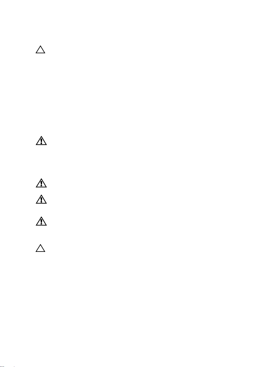
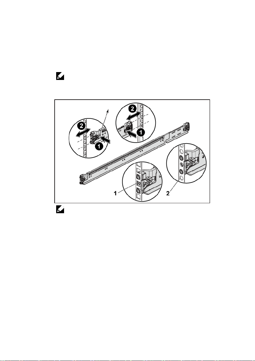
Push on the latch release buttons on the end piece midpoints to open
the rail latches. See Figure 1.
2
Align the end pieces of the rails on the vertical rack flanges to seat
the pegs in the bottom hole of the first U and the top hole of the
second U. See Figure 1.
NOTE:
The rails can be used in both square-hole (item 1 in the following figure)
and round-hole racks (item 2 in the following figure).
Figure 1 Pushing the Latch Release Buttons
NOTE:
To remove the rails, push on the latch release button on the end piece
midpoint and unseat each rail.
Getting Started With Your System | 4
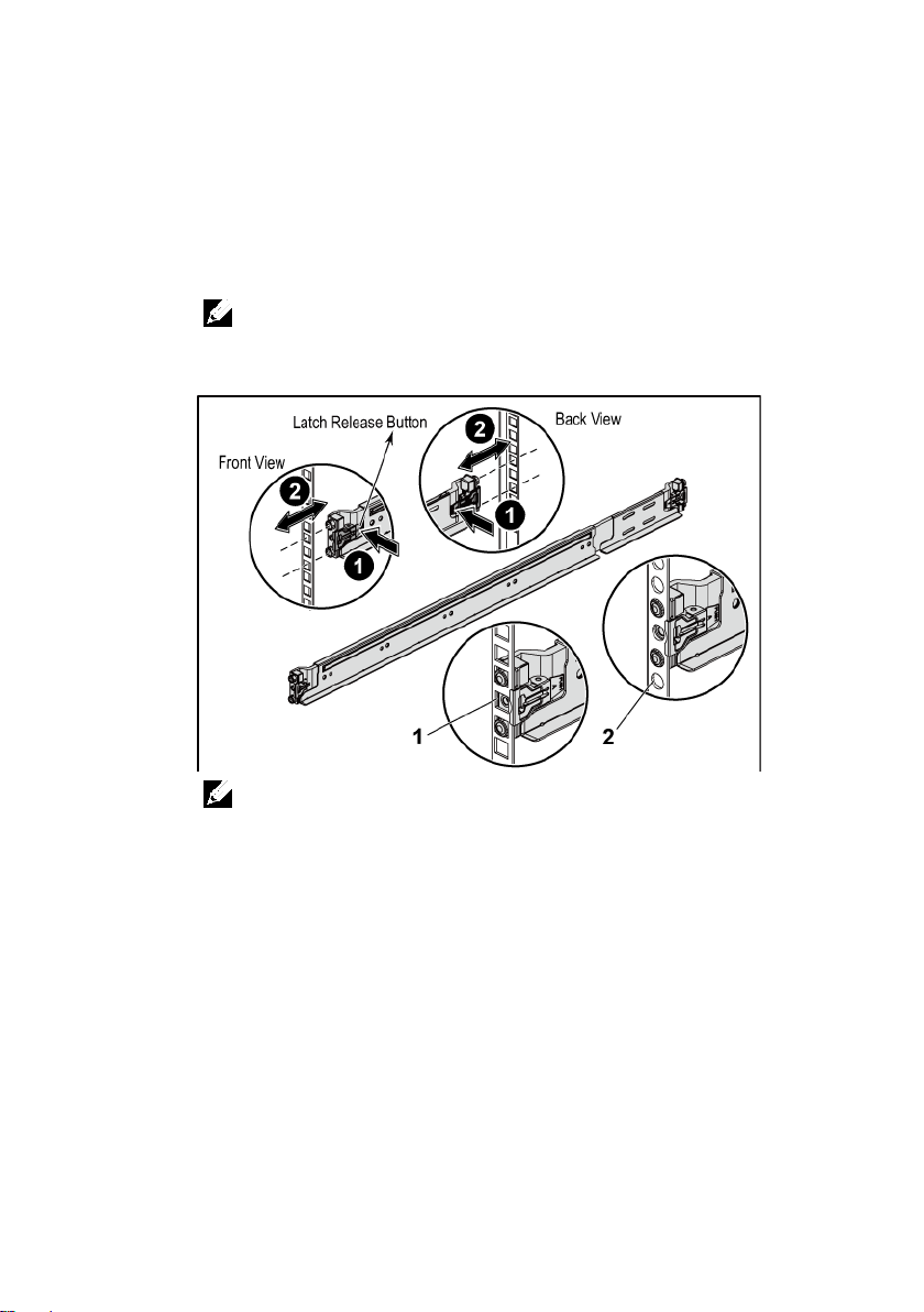
3
Engage the end of the rails and release the latch release button to
have the latches locked in place. See Figure 2.
Figure 2 Releasing the Latch Release Buttons
Getting Started With Your System | 5
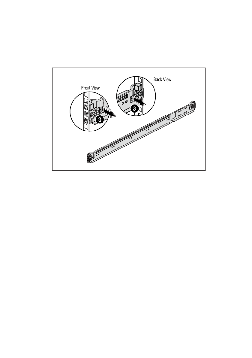
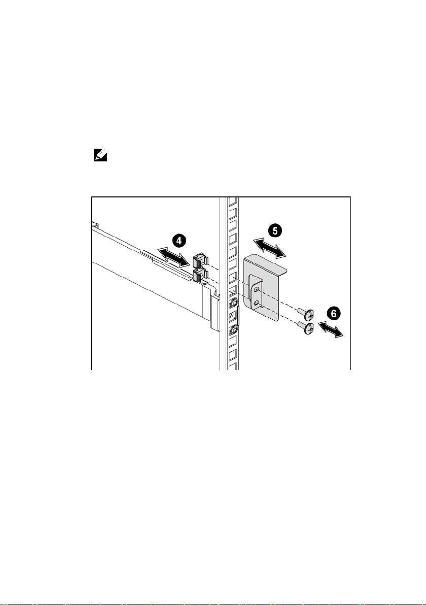
4
On each vertical rack flange on the back, put two screw bases into
the two square holes right above the rail. See Figure 3.
5
Install the chassis stabilizer shipping brackets (optional) on the back
rack flanges. See Figure 3.
6
Simultaneously fasten the screws. See Figure 3.
NOTE:
To transport systems already installed in the rack, ensure that the two
chassis stabilizer shipping brackets (optional) are in place.
Figure 3 Installing the Chassis Stabilizer Shipping Brackets
Getting Started With Your System | 6
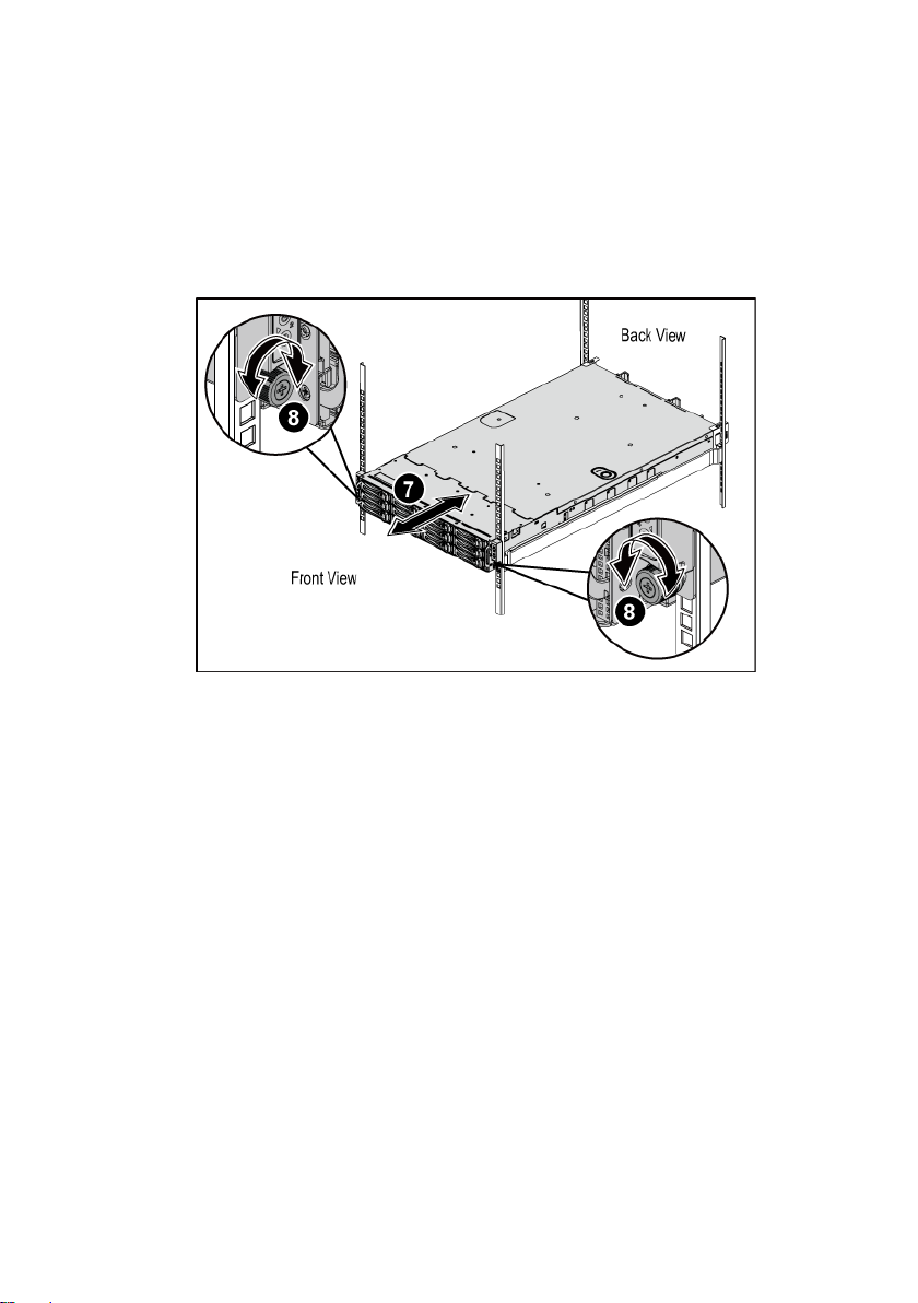
7
Slide the system into the rack. See Figure 4.
8
Tighten the thumbscrews to secure the ears of the system to the front
of the rack flanges. See Figure 4.
Figure 4 Installing the Chassis onto the Rack.
Getting Started With Your System | 7
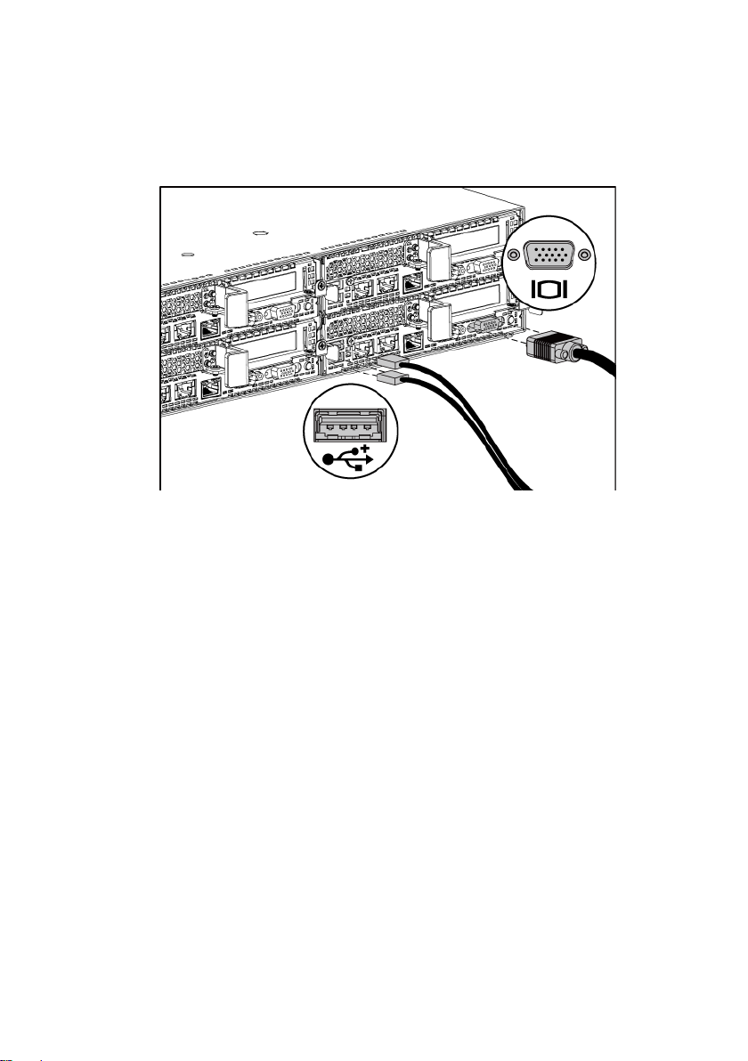
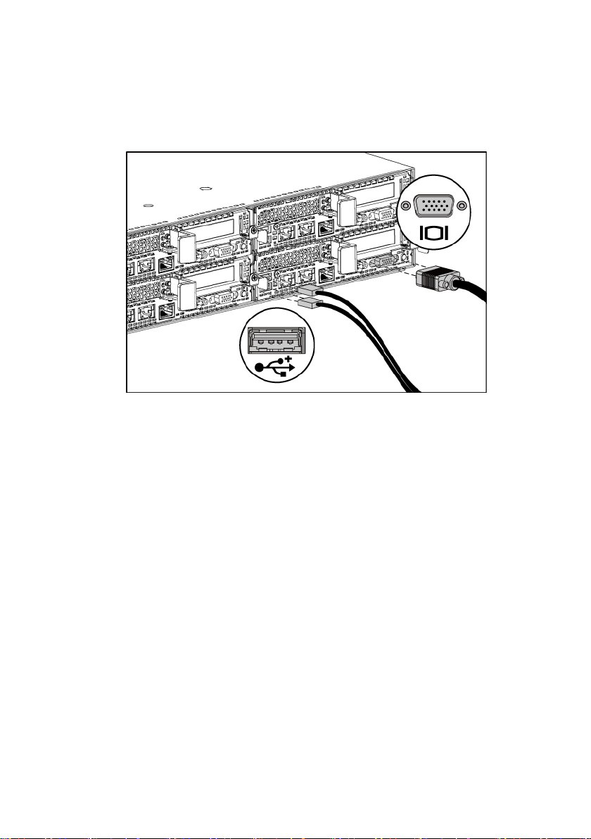
Optional-Connecting the Keyboard, Mouse, and Monitor
Figure 5 Connecting the Keyboard, Mouse and Monitor
Connect the keyboard, mouse, and monitor (optional).
The connectors on the back of your system have icons indicating which cable to
plug into each connector. Be sure to tighten the screws (if any) on the monitor’s
cable connector.
Getting Started With Your System | 8

Connecting the Power Cable(s)
Figure 6 Connecting the Power Cable
Connect the system’s power cable(s) to the system and, if a monitor is used,
connect the monitor’s power cable to the monitor. Plug the other end of the
power cables into a grounded electrical outlet or a separate power source such as
an uninterrupted power supply or a power distribution unit.
NOTE:
The power input: 110 V and 220 V.
Getting Started With Your System | 9
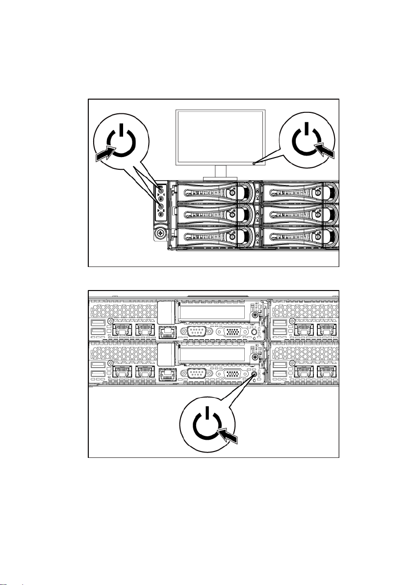
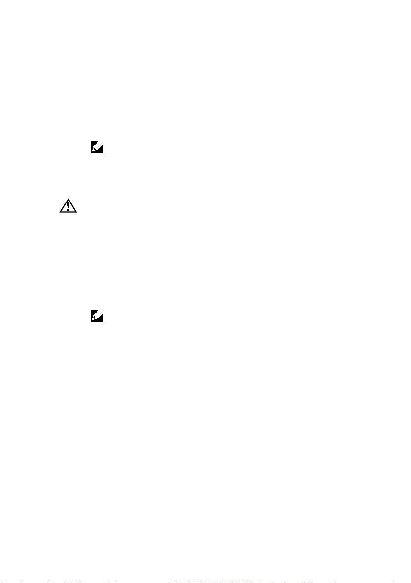
Turning on the System
Figure 7 Pressing the Power Button on the Front and the Monitor
Figure 8 Pressing the Power Button on the Back
Press the power button(s) either on the front or back of the system and on the
monitor. The power indicators should light green.
Getting Started With Your System | 10
Complete the Operating System Setup
To install an operating system for the first time, see the installation and
configuration documentation for your operating system. Be sure the operating
system is installed before installing hardware or software not purchased with the
system.
NOTE:
For the latest information on supported operating systems, see
dell.com/ossupport
.
Other Information You May Need
The Hardware Owner’s Manual provides information about system features and
describes how to troubleshoot the system and install or replace system
components. This document is available at
Dell systems management application documentation provides information
about installing and using the systems management software. This document is
available online at
WARNING: See the safety and regulatory information that shipped with your
system. Warranty information may be included within this document or as a
separate document.
support.dell.com/manuals
support.dell.com/manuals
NOTE:
Always check for updates on
updates first because they often supersede information in other documents.
.
support.dell.com/manuals
.
and read the
Getting Started With Your System | 11

NOM Information (Mexico Only)
Model number
B08S
Frequency
50/60 Hz
The following information is provided on the device described in this document
in compliance with the requirements of the official Mexican standards (NOM):
Importer Dell Inc. de México, S.A. de C.V.
Paseo de la Reforma 2620-11° Piso
Col. Lomas Atlas
11950 México, D.F.
Supply voltage 100-240 V AC with 1200 W Power
200-240 V AC with 1400 W Power
Current consumption 12-8 Amps with 1200 W Power
9 Amps with 1400 W Power
Getting Started With Your System | 12

Technical Specifications
Processor (Per System Board)
Expansion slots
2U node: full height and half height
UDIMM
Memory module sockets
16 x DDR3 DIMM sockets
Minimum RAM
2 GB
Maximum RAM
512 GB
Drives
Processor type Two Intel Xeon Processor E5-2600 Series
product family
Chipset
Chipset type Intel PCH-J chipset
Expansion Bus (Per System Board)
Bus type PCI Express Generation 3
PCIe Two x16, PCIe slots
1U node: half height
Mezzanine card PCIe One x8, Mezzanine slot
NOTE:
The mezzanine slot is only active in 2-
processor configuration.
Memory (Per System Board)
Architecture 16 x DDR3 1600/1333 MHz RDIMM or
Memory module capacities 2 GB, 4 GB, 8 GB, 16 GB or 32GB
Hard drives Up to twelve 3.5-inch, hot-swappable
SAS/SATA drives or twenty-four 2.5-inch,
hot-swappable SAS/SATA drives
NOTE:
SAS hard drives are supported by add-on card.
Getting Started With Your System | 13

Connectors (Per System Board)
Back
NIC
Two RJ-45 (10/100/1000 Mbps Ethernet)
COM 9-pin, DTE, 16550-compatible
USB
Two 4-pin, USB 2.0-compliant
Video
15-pin D-Sub VGA
Internal
Micro-SD socket
SD riser card memory socket
Video (Per System Board)
AST1300
AC power supply (per power supply)
Wattage
1200 W
Heat dissipation
4016.251 BTU/hr maximum
cannot exceed 35 Amps (peak).
Management port RJ-45 Ethernet port for remote management
access. The management LAN speed is
10Mbps/100Mbps.
Video type AST2300 on-board video controller, or
Video memory 16 MB
Power
NOTE:
The system doesn’t support a mixed installation of 1200 W and 1400 W power supplies.
NOTE:
Both of these two PSUs are swappable, and they can support hot swap in any condition if
system has power throttling feature.
Voltage 100-240 VAC, 50/60 Hz, maximum input
current: 12.0-8.0 Amps
NOTE:
For 1200 W power supply, output 1200 W is for
high line (input 200-240 VAC), output 1023 W is for low
line (input 100-120 VAC).
Maximum inrush current Initial In-rush Current cannot exceed 55
Getting Started With Your System | 14
Amps (peak). Secondary In-rush Current

Wattage
1400 W
Voltage 200-240 VAC, 50-60 Hz, maximum input
Heat dissipation
6024.376 BTU/hr maximum.
cannot exceed 25 Amps (peak).
Battery (per system board)
Width
44.8 cm (17.6 in)
Depth
79.0 cm (31.1 in)
configuration)
Temperature
hour
current: 9.0 Amps
Maximum in-rush current Initial In-rush Current cannot exceed 55
Amps (peak). Secondary In-rush Current
System battery
Physical
CR 2032 3.0-V lithium ion coin cell
Height 8.68 cm (3.42 in)
Weight (maximum
41 kg (90.38 lb) (with 12*3.5” HDD)
Weight (empty) 15.3 kg (33.73 lb) (with 2.5” HDD bay)
16.2 kg (35.71 lb) (with 3.5” HDD bay)
Environmental
NOTE:
For additional information about environmental measurements for specific system
configurations, see
www.dell.com/environmental_datasheets
.
Operating 10° to 35°C (50° to 95°F) with a maximum
temperature gradation of 10°C per hour
NOTE:
For altitudes above 2950 feet, the maximum
operating temperature is derated 1°F/550 ft.
CAUTION:
and hard drives supported on 1U and 2U node
configurations, with 130W (4 and 8 core) and 135W
processors, depends on the power supply installed.
The maximum number of memory modules
Storage –40° to 65°C (–40° to 149°F) with a
maximum temperature gradation of 20°C per
Getting Started With Your System | 15

Relative humidity
Operating 20% to 80% (noncondensing) with a
hour
Maximum vibration
Storage
1.88 Grms at 10–500 Hz for 15 min
Maximum shock
G for 2.6 ms in the operational orientation
Altitude
Operating
-15.2 to 3,048 m (-50 to 10,000 ft.)
Airborne Contaminant Level
maximum humidity gradation of 10% per
Storage 5% to 95% (noncondensing)
Operating 0.26 Grms at 5–350 Hz
Operating One shock pulse in the positive z axis
(one pulse on each side of the system) of 31
Storage Six consecutively executed shock pulses in
the positive and negative x, y, and z axes
(one pulse on each side of the system) of 71
G for up to 2 ms;
Six consecutively executed shock pulses in
the positive and negative x, y, and z axes
(one pulse on each side of the system) of 27
G faired square wave pulse with velocity
change at 235 inches/second (597
centimeters/second)
Storage -15.2 to 10,668 m (-50 to 35,000 ft.)
Class
Getting Started With Your System | 16
G1 as defined by ISA-S71.04-1985

Dell PowerEdge
C6220
系统使用入门

注、小心和警告
注:
小心:“小心”表示如果不遵循说明,就有可能损坏硬件或导致数据丢失。
警告:“警告”表示可能会导致财产损失、人身伤害甚至死亡。
“注”表示可以帮助您更好地使用计算机的重要信息。
______________
本文档中的信息如有更改,恕不另行通知。
© 2013 Dell Inc.
未经 Dell Inc. 书面许可,严禁以任何形式复制这些材料。
本文中使用的商标:Dell™、DELL 徽标和 PowerEdge™ 是 Dell Inc. 的商标。Intel®
和 Intel® Xeon® 是 Intel Corporation 在美国 和其他国家或地区的注册商标。Red Hat
Enterprise Linux® 和 Enterprise Linux® 是 Red Hat, Inc. 在美国和/或其他国家或地区
的注册商标。Novell® 和 SUSE™ 分别是 Novell Inc. 在美国和其他国家/地区的注册
商标和商标。Citrix® 和 XenServer® 是 Citrix Systems, Inc. 在美国和/或其他国家/地
区的注册商标或商标。VMware® 是 VMware, Inc. 在美国或其他国家/地区的注册商
标或商标。
本出版物中可能使用其它商标和产品名称来指拥有相应商标和产品名称的公司或其
产品。Dell Inc. 对不属于自己的商标和商品名称不拥有任何专有权。
保留所有权利。
管制型号 B08S
2013 年 9 月 P/N CRP9M Rev. A04
小心:受限访问位置
警告:执行下列步骤之前,请先阅读并遵循系统随附的安全说明。
警告:需要提起系统时,请让其他人进行协助。为避免受伤,请勿尝试独自提
起系统。
警告:系统并未固定到机架上,也并没有安装在滑轨上。为避免人身伤害或系
统损坏,在安装和拆卸时,必须给系统提供足够的支撑。
警告:为避免可能的电击伤害,安装机架时需要第三根导线的安全接地线。机
架设备必须为系统提供足够的通风以维持适当的冷却效果。
小心:在方孔机架中安装导轨时,务必确保方形插销穿过方孔。
此服务器仅用于安装在由
两个条件的受限访问位置中:
•
仅维修人员或对该位置施加限制的理由以及应当采取的防备措施已
完全领会的 用户,方可对此服务器进行访问。
•
访问是通过使用工具或锁和钥匙,或其它安全手段来实现,并且由
负责该位置的管理机构来控制。
IEC 60950-1: 2001 的 Cl. 1.2.7.3
安装和配置
安装免工具拆装导轨解决方案
定义的满足下列
系统使用入门 | 19
1
注:
注:
按下尾段正中央的闩锁释放按钮以打开滑轨闩锁。请参阅图 1。
2
在机架垂直凸缘上对齐滑轨的尾段,将插销分别插入第一个
型螺栓的底孔中和第二个
滑轨在方孔机架(下图中的项 1)和圆孔机架(下图中的项 2)中均可
使用。
图
1
按下闩锁释放按钮
s
U
型螺栓的顶孔中。请参阅图 1。
U
闩锁释放按钮
背面视图
正面视图
要卸下滑轨,请按下尾段正中央的闩锁释放按钮并取出每根滑轨。
系统使用入门 | 20

3
接入各个滑轨的尾端并松开闩锁释放按钮以使闩锁锁定到位。
请参阅图 2。
图
2
松开闩锁释放按钮
正面视图
背面视图
系统使用入门 | 21
4
注:
在背面的每个垂直机架凸缘上,将两颗螺钉座放入机架正上方
的两个方孔内。请参阅图 3。
5
将运输时稳固机箱的支架(可选件)安装在机架背面的凸缘上。
请参阅图
6
同时拧紧两颗螺钉。请参阅图 3。
位(可选)。
图
3
安装运输时稳固机箱的支架
3。
要运输已经安装在机架上的系统,请确保两个运输时稳固机箱的支架到
背面视图
系统使用入门 | 22

7
将系统滑入到机架中。请参阅图 4。
8
拧紧指旋螺钉,将系统的耳柄固定到机架凸缘正面。请参阅图 4。
图
4
将机箱安装到机架中。
背面视图
正面视图
系统使用入门 | 23
可选
—
连接键盘、鼠标和显示器
图
5
连接键盘、鼠标和显示器
连接键盘、鼠标和显示器(可选)。
系统背面的连接器附有图标,这些图标指示了要插入每个连接器的电缆。
确保拧紧显示器电缆连接器上的螺钉(如果有)。
系统使用入门 | 24
 Loading...