

Dell PowerEdge C6145 User Manual

Dell PowerEdge C6145
Hardware Owner’s
Systems
Manual
Regulatory Model B05S

Notes, Cautions, and Warnings
NOTE:
CAUTION: A CAUTION indicates potential damage to hardware or loss
of data if instructions are not followed.
WARNING: A WARNING indicates a potential for property damage,
personal injury, or death.
Information in this publication is subject to change without notice.
A NOTE indicates important information that helps you make
better user of your computer.
© 2013 Dell Inc. All rights reserved.
Reproduction of these materials in any manner whatsoever without the written permission of
Dell Inc. is strictly forbidden.
Trademarks used in this text: Dell™, the DELL logo, and PowerEdge™ are trademark s of Dell
Inc. AMD
Other trademarks and trade names may be used in this publication to refer to either the entities
claiming the marks and names or their products. Dell Inc. disclaims any proprietary interest in
trademarks and trade names other than its own.
Regulatory Model B05S
May 2013 Rev. A05
®
is a regist ered trademark of Ad v anced Micro Devices, Inc.

Contents
1 About Your System ...................................................................... 11
Accessing System Features During Startup ................................................. 11
Front-Panel Features and Indicators .............................................................. 12
Hard-Drive Indicator Patterns ......................................................................... 15
Back-Panel Features and Indicators ............................................................. 17
NIC Indicator Codes .......................................................................................... 20
Power and System Board Indicator Codes ................................................... 22
Power Supply Indicator Codes ....................................................................... 23
BMC Heart Beat LED ......................................................................................... 24
Post Error Code .................................................................................................. 25
Collecting System Event Log (SEL) for Investigation ........................... 25
Post Error Code Event .............................................................................. 43
Other Information You May Need ........................................................... 44
Recovery Mode .................................................................................................. 45
2 Using the System Setup Program ............................................ 46
Start Menu .......................................................................................................... 46
System Setup Options at Boot ......................................................................... 46
Console Redirection ......................................................................................... 47
Main Menu ......................................................................................................... 49
Main Screen .............................................................................................. 49
BIOS Firmware .......................................................................................... 50
System Firmware ...................................................................................... 50
Contents | 3

Product Information.................................................................................. 50
Processor ................................................................................................... 51
System Memory ........................................................................................ 51
Advanced Menu ................................................................................................ 52
CPU Configuration .................................................................................... 53
Power Management Maximum Performance ...................................... 56
Power Management OS Control ............................................................. 57
Power Management Advanced Platform Management Link ............. 58
Memory Configuration ............................................................................. 59
IDE Configuration ...................................................................................... 60
USB Configuration .................................................................................... 64
PCI Configuration ...................................................................................... 65
Hyper Transport Configuration ............................................................... 69
I/O Virtualization ........................................................................................ 70
Boot Menu .......................................................................................................... 71
Boot Settings Configuration .................................................................... 72
Security Menu ................................................................................................... 80
Server Menu ....................................................................................................... 82
4 | Contents
Boot Device Priority.................................................................................. 74
Hard Disk Drives ....................................................................................... 75
Removable Drives ..................................................................................... 76
CD/DVD Drives .......................................................................................... 77
USB Drives ................................................................................................. 78
Network Drives ......................................................................................... 79
System Management ............................................................................... 84
Remote Access Configuration ................................................................ 85

IPMI Configuration ................................................................................... 87
Exit Menu............................................................................................................ 91
Command Line Interface for Setup Options .................................................. 92
3 Installing System Components ............................................... 103
Safety Instructions .......................................................................................... 103
Recommended Tools ...................................................................................... 103
Inside the System ............................................................................................ 104
Hard Drives ....................................................................................................... 105
Removing a Hard-Drive Blank ............................................................... 105
Installing a Hard-Drive Blank ................................................................ 106
Removing a Hard-Drive Carrier ............................................................. 106
Installing a Hard-Drive Carrier .............................................................. 107
Removing a Hard Drive From a Hard-Drive Carrier ............................ 108
Installing a Hard Drive Into a Hard-Drive Carrier ............................... 109
Power Supplies ............................................................................................... 110
Removing a Power Supply ..................................................................... 113
Installing a Power Supply ...................................................................... 114
System-Board Assembly ................................................................................ 115
Removing a System-Board Assembly .................................................. 115
Installing a System-Board Assembly ................................................... 116
Air Ducts ........................................................................................................... 116
Removing the Air Duct ........................................................................... 116
Installing the Air Duct ............................................................................. 117
Heat Sinks ........................................................................................................ 118
Removing the Heat Sink ......................................................................... 118
Contents | 5

Installing the Heat Sink .......................................................................... 119
Processors........................................................................................................ 121
Removing a Processor ........................................................................... 122
Installing a Processor ............................................................................ 124
Expansion-Card Assembly and Expansion Card ........................................ 125
Removing the Expansion Card .............................................................. 125
Installing the Expansion Card ................................................................ 127
LSI 9260-8i Card ............................................................................................... 129
Removing the LSI 9260-8i Card .............................................................. 129
Installing the LSI 9260-8i Card ............................................................... 132
Cable Routing for LSI 9260-8i Card ....................................................... 133
LSI 9260-8i RAID Battery (Optional) .............................................................. 135
Removing the LSI 9260-8i RAID Battery ............................................... 135
Installing the LSI 9260-8i RAID Battery ................................................ 136
Removing the LSI 9260-8i RAID Battery Carrier .................................. 137
Installing the LSI 9260-8i RAID Battery Carrier ................................... 138
LSI 9265-8i Card ............................................................................................... 139
LSI 9265-8i RAID Battery (Optional) .............................................................. 145
Expansion-Card Connector ............................................................................ 149
6 | Contents
Removing the LSI 9265-8i Card .............................................................. 139
Installing the LSI 9265-8i Card ............................................................... 142
Cable Routing for LSI 9265-8i Card ....................................................... 143
Removing the LSI 9265-8i RAID Battery Assembly ............................. 145
Installing the LSI 9265-8i RAID Battery Assembly .............................. 146
Removing the LSI 9265-8i RAID Battery ............................................... 147
Installing the LSI 9265-8i RAID Battery ................................................ 148

Removing the Expansion-Card Connector........................................... 149
Installing the Expansion-Card Connector ............................................ 150
Mezzanine Card ............................................................................................... 151
Removing the SAS Mezzanine Card ..................................................... 151
Installing the SAS Mezzanine Card ...................................................... 153
Cable Routing for SAS Mezzanine Card .............................................. 154
Removing the 10GbE Mezzanine Card ................................................. 155
Installing the 10GbE Mezzanine Card ................................................... 157
Removing the Mellanox Card ................................................................ 158
Installing the Mellanox Card ................................................................. 160
Mezzanine-Card Bridge Board ...................................................................... 161
Removing the Mezzanine-Card Bridge Board .................................... 161
Installing the Mezzanine-Card Bridge Board ...................................... 162
System Memory ............................................................................................... 163
Supported DIMM Configuration ........................................................... 163
Removing the Memory Modules ........................................................... 166
Installing the Memory Modules ............................................................ 167
System Battery ................................................................................................. 169
Replacing the System Battery ............................................................... 169
System Board ................................................................................................... 171
Removing a System Board..................................................................... 171
Installing a System Board ...................................................................... 172
Opening and Closing the System .................................................................. 173
Opening the System................................................................................ 174
Closing the System ................................................................................. 174
Cooling Fans ..................................................................................................... 175
Contents | 7

Removing a Cooling Fan ......................................................................... 175
Installing a Cooling Fan .......................................................................... 176
Middle Planes .................................................................................................. 177
Removing the Middle Planes ................................................................. 177
Installing the Middle Planes .................................................................. 182
Backplanes ...................................................................................................... 184
Removing the 3.5" Hard-Drive Backplane ............................................ 184
Installing the 3.5" Hard-Drive Backplane ............................................. 187
Power Distribution Boards ............................................................................ 188
Removing a Power Distribution Board ................................................. 188
Installing a Power Distribution Board .................................................. 190
Cable Routing for Power Distribution Board ....................................... 191
Fan Controller Board ....................................................................................... 192
Removing the Fan Controller Board ..................................................... 192
Installing the Fan Controller Board....................................................... 193
Cable Routing for Fan Control Board .................................................... 194
Expander Card (Optional) ............................................................................... 195
Front Panels ..................................................................................................... 200
Sensor Boards ................................................................................................. 204
8 | Contents
Removing the Expander Card ................................................................ 195
Installing the Expander Card ................................................................. 199
Removing the Front Panel ...................................................................... 200
Installing the Front Panel ....................................................................... 203
Removing the Sensor Board for 3.5” Hard Drive System .................. 204
Installing the Sensor Board for 3.5” Hard Drive System ................... 206
Removing the Sensor Board for 2.5” Hard Drive System .................. 208

Installing the Sensor Board for 2.5” Hard Drive System ................... 210
4 Troubleshooting Your System ................................................. 212
Safety First – For You and Your System ....................................................... 212
Installation Problems ..................................................................................... 212
Troubleshooting System Startup Failure ..................................................... 213
Troubleshooting External Connections ....................................................... 213
Troubleshooting the Video Subsystem ........................................................ 213
Troubleshooting a USB Device ..................................................................... 213
Troubleshooting a Serial I/O Device ............................................................ 214
Troubleshooting a NIC .................................................................................... 215
Troubleshooting a Wet System ..................................................................... 216
Troubleshooting a Damaged System ........................................................... 217
Troubleshooting the System Battery ............................................................ 217
Troubleshooting Power Supplies ................................................................. 218
Troubleshooting System Cooling Problems ................................................ 219
Troubleshooting a Fan .................................................................................... 220
Troubleshooting System Memory ................................................................. 220
Troubleshooting a Hard Drive ....................................................................... 222
Troubleshooting a Storage Controller ......................................................... 223
Troubleshooting Expansion Cards ................................................................ 225
Troubleshooting Processors ......................................................................... 226
IRQ Assignment Conflicts .............................................................................. 228
5 Jumpers and Connectors ......................................................... 229
System Board Connectors .............................................................................. 229
Backplane Connectors ................................................................................... 231
Contents | 9

3.5" Hard-Drive Backplane With CPLD ................................................. 231
3.5" Hard-Drive Backplane With Expander .......................................... 232
2.5" Hard-Drive Backplane With Expander .......................................... 233
2.5" Hard-Drive Backplane Expander Card Connectors .................... 234
Middle Plane Connectors .............................................................................. 235
Expansion Card Connectors .......................................................................... 236
SAS Mezzanine Card Connectors ................................................................. 237
10GbE Mezzanine Card Connectors .............................................................. 238
Fan Controller Board Connectors ................................................................. 239
Power Distribution Board Connectors ......................................................... 240
Sensor Board Connectors .............................................................................. 241
Switch and Jumper Settings ......................................................................... 242
System Configuration Switch Settings ................................................ 242
3.5" Backplane With CPLD Jumper Settings ....................................... 243
3.5" Backplane With Expander Jumper Settings ................................ 244
2.5" Backplane Expander Card Jumper Settings ................................ 245
6 Getting Help ................................................................................ 246
Contacting Dell ................................................................................................ 246
7 Index ............................................................................................ 247
10 | Contents

1
About Your System
Accessing System Features During Startup
The following keystrokes provide access to system features during startup.
Keystroke Description
<F2> Enters the System Setup program. See “Start Menu” on page 46.
<F11> Enters the BIOS Boot Manager. See “System Setup Options at
Boot” on page 46.
<F12> Starts Preboot eXecution Environment (PXE) boot.
<Ctrl><C> Enters the SAS 2008 Daughter Card Configuration Utility. For
more information, see the SAS adapter documentation.
<Ctrl><H> Enters the LSI 9260 configuration utility. For more information,
see the documentation for your SAS RAID card.
<Ctrl><S> Enters the utility to configure NIC settings for PXE boot. For
more information, see the documentation for your integrated
NIC.
<Ctrl><HOME> BIOS recovery during Boot Block.
About Your System | 11
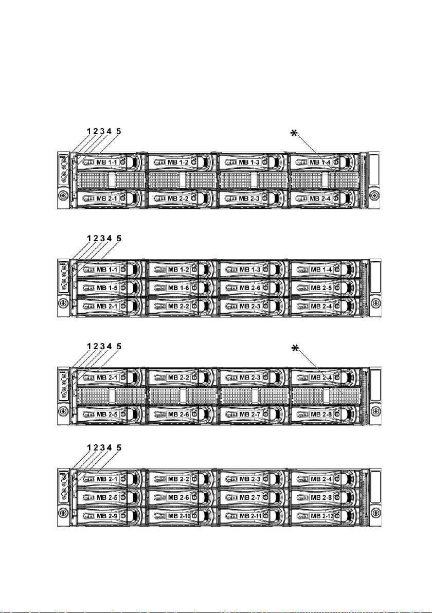
Front-Panel Features and Indicators
Figure 1-1. Front Panel−3.5” x8 Hard Drives With Two Motherboards
Figure 1-2.
Figure 1-3.
Figure 1-4.
Front Panel−3.5” x12 Hard Drives With Two Motherboards
Front Panel−3.5” x8 Hard Drives With One Motherboard
Front Panel−3.5” x12 Hard Drives With One Motherboard
12 | About Your System
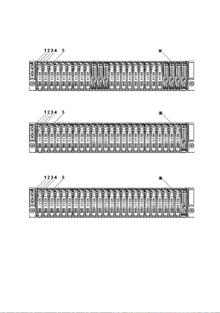
Figure 1-5. Front Panel−2.5” x18 Hard Drives With Two Motherboards
Figure 1-6. Front Panel−2.5” x24 Hard Drives With Two Motherboards
Figure 1-7. Front Panel−2.5” x24 Hard Drives With One Motherboard
About Your System | 13

1,3
Power-on indicator/
The power-on indicator lights
NOTE:
NOTE:
NOTE:
Item Indicator, Button
Or Connector
power button
(motherboards 1,2)
2,4 System identification
indicator/button
(motherboards 1,2)
Icon Description
when the system power is on.
The power button controls the
DC power supply output to the
system.
When powering on the
system, the video monitor can take
from several seconds to over 2
minutes to display an image,
depending on the amount of
memory installed in the system.
On ACPI-compliant
operating systems, turning off the
system using the power button
causes the system to perform a
graceful shutdown before power to
the system is turned off.
To force an ungraceful
shutdown, press and hold the
power button for 5 seconds.
The identification button can be
used to locate a particular system
and motherboard within a chassis.
When the button is pushed, the
blue system status indicator on
the front blinks until the button
is pushed again.
5 Hard Drives Up to twelve hot-swappable 3.5"
hard drives.
Up to twenty four hot-swappable
2.5" hard drives.
* Drive Cover Different for 2.5" hard drive
system and 3.5" hard drive system.
14 | About Your System

Hard-Drive Indicator Patterns
Predicted
Off/
On 500 ms
Off 500 ms
Drive Identify/
Blinking
On 250 ms
Off
Figure 1-8. Hard-Drive Indicators
1 hard-drive activity indicator
(green)
Table 1-1. Hard-Drive Status Indicators−For 3.5" Hard-Drive Backplane With CPLD
Hard
Drive
Type
SAS Slot Empty Off Off Off
Function
Drive Online/Access
Drive Failed Off/
Drive
Rebuilding
Drive
Rebuilding
Abort
Failure
(SMART)
Preparing for
removal
Activity LED Status LED
Green Green Amber
Blinking
when active
Blinking
when active
Blinking
when active
Off/
Blinking
when active
Blinking
when active
when active
2 hard-drive status indicator (green and
amber)
On Off
Off On 150 ms
Off 150 ms
On 400 ms
Off 100 ms
On 3000 ms
Off 3000 ms
Off 3000 ms
Off 3000 ms
Off 500 ms
Off 1000 ms
Off 250 ms
Off
Off 3000 ms
Off 3000 ms
On 3000 ms
Off 3000 ms
On 500 ms
Off 1000 ms
About Your System | 15

Table 1-2. Hard-Drive Status Indicators−For 3.5" Hard-Drive Backplane With
Activity LED
Status LED
Expander
Hard Drive
Type
SAS Slot Empty Off Off Off
Function
Drive Online/Access
Drive Failed Off/
Drive
Rebuilding
Drive
Rebuilding
Abort
Predicted
Failure
(SMART)
Drive
Identify/
Preparing for
removal
Green Green Amber
Blinking
when active
Blinking
when active
Blinking
when active
Off/
Blinking
when active
Off/
Blinking
when active
Blinking
when active
On Off
Off On 125 ms
Off 125 ms
On 400 ms
Off 100 ms
On 3000 ms
Off 3000 ms
Off 3000 ms
Off 3000 ms
On 500 ms
Off 500 ms
Off 1000 ms
On 250 ms
Off 250 ms
Off
Off 3000 ms
Off 3000 ms
On 3000 ms
Off 3000 ms
Off 500 ms
On 500 ms
Off 1000 ms
Off
16 | About Your System
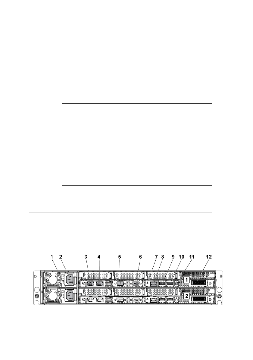
Table 1-3. Hard-Drive Status Indicators−For 2.5" Hard-Drive Backplane With
Activity LED
Status LED
Expander
Hard Drive
Type
SAS Slot Empty Off Off Off
Function
Drive Online/Access
Drive Failed Off/
Drive
Rebuilding
Drive
Rebuilding
Abort
Predicted
Failure
(SMART)
Drive
Identify/
Preparing for
removal
Green Green Amber
Blinking
when active
Blinking
when active
Blinking
when active
Off/
Blinking
when active
Off/
Blinking
when active
Blinking
when active
On Off
Off On 125 ms
Off 125 ms
On 400 ms
Off 100 ms
On 3000 ms
Off 3000 ms
Off 3000 ms
Off 3000 ms
On 500 ms
Off 500 ms
Off 1000 ms
On 250 ms
Off 250 ms
Off
Off 3000 ms
Off 3000 ms
On 3000 ms
Off 3000 ms
Off 500 ms
On 500 ms
Off 1000 ms
Off
Back-Panel Features and Indicators
Figure 1-9. Back Panel−Two Motherboards
About Your System | 17
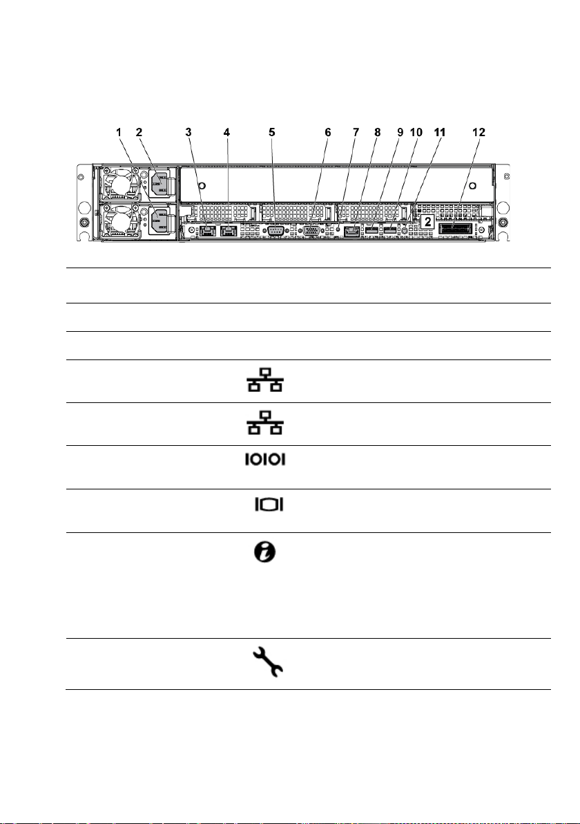
Figure 1-10. Back Panel−One Motherboard
4
NIC connector 2
Embedded 10/100/1000 NIC connectors.
Item Indicator, Button
Or Connector
1 Power supply 2 1100 W/1400 W
2 Power supply 1 1100 W/1400 W
Icon Description
3 NIC connector 1
5 Serial port
6 VGA port
7 System
identification
indicator
8 BMC management
port
Embedded 10/100/1000 NIC connectors.
Connects a serial device to the system.
Connects a VGA display to the system.
Both the system management software
and the identification buttons located on
the front can cause the indicator to flash
blue to identify a particular system and
system board. Lights amber when the
system needs attention due to a problem.
Dedicated management port.
18 | About Your System

NOTE:
video monitor can take from several
NOTE:
compliant operating
NOTE:
Item Indicator, Button
Or Connector
9 USB port 0
10 USB port 1
11 Power On/Off
button
12 IPASS connector Connects to external PCIE devices or a
Icon Description
Connects USB devices to the system. The
ports are USB 2.0-compliant.
Connects USB devices to the system. The
ports are USB 2.0-compliant.
The power button controls the DC power
supply output to the system.
When powering on the system, the
seconds to over 2 minutes to display an
image, depending on the amount of memory
installed in the system.
On ACPIsystems, turning off the system using the
power button causes the system to perform
a graceful shutdown before power to the
system is turned off.
To force an ungraceful shutdown,
press and hold the power button for five
seconds.
PCIE bus extender port.
About Your System | 19
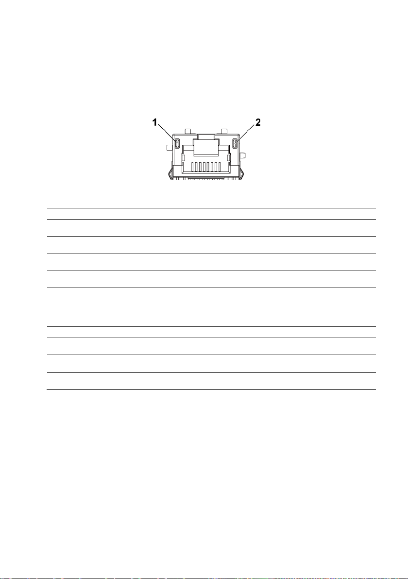
NIC Indicator Codes
when the
Figure 1-11. NIC Indicators
1 speed indicator 2 link/activity indicator
NIC Status Indicator (Speed) Condition
Solid green Linking at 100 Mbps speed
Blinking green Port identification with 10 or 100 Mbps speed
Solid amber Linking at 1 Gbps speed
Blinking amber Port identification with 1 Gbps speed
Off Linking at 10 Mbps speed
link/activity LED is green; no link when the
link/activity LED is off.
NIC Status Indicator (Link/Activity) Condition
Solid green LAN linking/No access
Blinking green LAN accessing
Off No link
20 | About Your System

Figure 1-12. NIC Indicators (BMC Management Port)
1 speed indicator
NIC Status Indicator (Speed) Condition
Green Linking at 100 Mbps speed
Off Linking at 10 Mbps speed when the
NIC Status Indicator (Link/Activity) Condition
Green LAN linking/Accessing
Off No link
2 link/activity indicator
link/activity LED is solid green;
no link when the link/activity LED is off
About Your System | 21

Power and System Board Indicator Codes
Table 1-4. Status Indicator Codes
The LEDs on the system front panel and back panel display status codes
during system startup. For location of the LEDs on the front panel, see
Figure 1-1 for 3.5
location of the LEDs on the back panel, see Figure 1-9.
Tab le 1-4 lists the status associated with the status codes.
Component Indicator Condition
Power-on
indicator
" hard drive and Figure 1-6 for 2.5" hard drive systems. For
Green Solid
Blinking
Off
Amber
Blinking
Off
Power On S0/S1
BMC critical condition event in Power On
mode S0/S1
Power Off mode S4/S5
BMC Critical condition event in Power On
mode S0/S1
BMC Critical condition event in Power Off
mode S4/S5
Power On S0/S1
Power Off S4/S5
System
identification
indicator
22 | About Your System
Blue Solid
Off
IPMI through Chassis Identify Command On
or ID Button Press ID On
IPMI through Chassis Identify Command Off
or ID Button Press ID Off
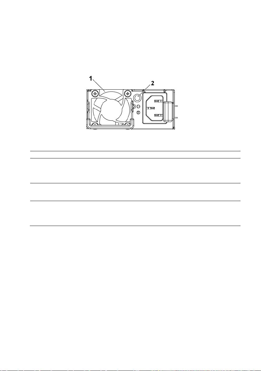
Power Supply Indicator Codes
1
power supply
2
AC power LED
Solid yellow
Power supply is at fault condition
Figure 1-13. Power Supply Status Indicator
AC Power LED Condition
Solid green Power supply is on (AC OK/DC OK) or in standby mode (100
VAC -120 VAC for 1023 W, 200 VAC-240 VAC for 1100 W, 200
VAC -240 VAC for 1400 W)
(UVP/OVP/OCP/SCP/OTP/Fan Fault)
Off Power supply is off or AC input voltage is out of normal
operating range (100 VAC-120 VAC for 1023 W, 200 VAC-240
VAC for 1100 W, 200 VAC-240 VAC for 1400 W)
About Your System | 23
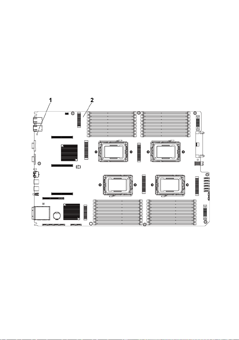
BMC Heart Beat LED
The system board provides BMC heart beat LED (CR2) for BMC debugs.
The BMC heart beat LED is green. When the system AC power is on, this
LED will light. When BMC firmware is ready, the BMC heart beat LED
will blink.
Figure 1-14. BMC Heart Beat LED
1 BMC heart beat LED 2 system board
24 | About Your System

Post Error Code
Collecting System Event Log (SEL) for Investigation
Whenever possible, the BIOS will output the current boot progress codes
on the video screen. Progress codes are 32-bit quantities plus optional data.
The 32-bit numbers include class, subclass, and operation information. The
class and subclass fields point to the type of hardware that is being
initialized. The operation field represents the specific initialization activity.
Based on the data bit availability to display progress codes, a progress code
can be customized to fit the data width. The higher the data bit, the higher
the granularity of information that can be sent on the progress port. The
progress codes may be reported by the system BIOS or option ROMs.
The Response section in the following table is divided into three types:
1 Warning or Not an error – The message is displayed on the screen. An
error record is logged to the SEL. The system will continue booting
with a degraded state. The user may want to replace the erroneous unit.
2 Pause – The message is displayed on the screen, an error is logged to
the SEL, and user input is required to continue. The user can take
immediate corrective action or choose to continue booting.
3 Halt – The message is displayed on the screen, an error is logged to the
SEL, and the system cannot boot unless the error is resolved. The user
needs to replace the faulty part and restart the system.
Error Code Error Message Error Cause Recovery Method
0000h Timer Error Timer8254 failed Board repair
0003h CMOS Battery Low CMOS battery low Change battery
0004h CMOS Setting Wrong Diagnostic status byte
shown an error
0005h CMOS Checksum Bad CMOS checksum
incorrect or BIOS update
000Bh CMOS Memory Size
Wrong
000Ch RAM Read/Write Test
Failed
Base memory size error Change DIMM or
No usable system
memory
Load CMOS
default setting
Load CMOS
default setting
board repair
Change DIMM
About Your System | 25

Error Code Error Message Error Cause Recovery Method
S.M.A.R.T. Status BAD,
0012h CMOS Date/Time Not
Set
0040h Refresh Timer Test
Failed
0041h Display Memory Test
Failed
0044h DMA Controller Error Unrecoverable system-
0045h DMA-1 Error Unrecoverable system-
0046h DMA-2 Error Unrecoverable system-
0048h Password Check Failed Preboot user password
004Ah ADM Module Error Unspecified Board repair
004Bh Language Module Error 7 Unspecified Board repair
005Dh S.M.A.R.T. Command
Failed
Backup and Replace
005Eh Password Check Failed Other preboot password
0060h Primary Master Hard
Disk Error
0061h Primary Slave Hard Disk
Error
0062h Secondary Master Hard
Disk Error
0063h Secondary Slave Hard
Disk Error
0080h Primary Master Drive-
ATAPI Incompatible
0081h Primary Slave Drive-
ATAPI Incompatible
Indicate invalid
date/time in CMOS
diagnostic status byte
Unrecoverable systemboard failure
Unrecoverable systemboard failure
board failure
board failure
board failure
violation
HDD/ATAPI/IDE device
failure
violation
HDD/ATAPI/IDE device
failure
HDD/ATAPI/IDE device
failure
HDD/ATAPI/IDE device
failure
HDD/ATAPI/IDE device
failure
HDD/ATAPI/IDE device
failure
HDD/ATAPI/IDE device
failure
Reset Date/Time
Board repair
Board repair
Board repair
Board repair
Board repair
Clear password by
switch
Change HDD
Clear password by
switch
Change HDD
Change HDD
Change HDD
Change HDD
Change HDD
Change HDD
26 | About Your System

Error Code Error Message Error Cause Recovery Method
0082h Secondary Master
Drive-ATAPI
Incompatible
0083h Secondary Slave Drive-
ATAPI Incompatible
0166h CPU Frequency
mismatch!
0167h CPUID mismatch! CPU mix installed is not
0168h L1 cache size mismatch! CPU mix installed is not
0169h L2 cache size mismatch! CPU mix installed is not
016Ah CPU Patch level
mismatch!
4168h DIMM CRC Error or be
ignore POST Error
4169h DIMM Chip Select
Disable, Test Fail
5120h CMOS cleared by
jumper
5122h Password cleared by
jumper
8104h Warning! Port 60h/64h
emulation is not
supported by this USB
Host Controller!!!
8105h Warning! EHCI
controller disabled. It
requires 64 bit data
support in the BIOS.
8601h Error: BMC Not
Responding
8701h Insufficient Runtime
space for MPS data!!
System may operate in
PIC or Non-MPS mode.
8702h
No enough APIC ID in Check APIC failed
HDD/ATAPI/IDE device
failure
HDD/ATAPI/IDE device
failure
CPU mix installed is not
support
support
support
support
CPU mix installed is not
support
DIMM bad Change DIMM
DIMM bad Change DIMM
CMOS clear by jumper No action
Password clear by jumper No action
Not supported by the HC Board repair
Check whether this host
controller needs 64 bit
data structure or not
BMC chip does not find Board repair
Failed to copy the
MPTable to F000 or
E000 shadow RAM
Change HDD
Change HDD
Install same model
CPU
Install same model
CPU
Install same model
CPU
Install same model
CPU
Install same model
CPU
Board repair
Board repair
Board repair
About Your System | 27

Error Code Error Message Error Cause Recovery Method
local APIC ID may solve
Sensor#
Sensor
Name
Event
Event Log
Sensor Type: Temperature
Processor 1 Temp
range 0-0Fh can be
assigned to IO APICs.
(Re-assigning CPUs’
this issue)
MPS Table is not built!
System may operate in
PIC or Non-MPS mode.
BMC
Processor 1 Temp
Upper non-critical event
asserted
Temperature Upper Non-
Critical - Going High -
Asserted
61h
28 | About Your System
Processor 1
Temp
Upper critical event
asserted
Upper non-recoverable
event asserted
Upper non-critical event
deasserted
Upper critical event
deasserted
Upper non-recoverable
event deasserted
Temperature Upper
Critical - Going High -
Asserted
Processor 1 Temp
Temperature Upper Non-
Recoverable - Going High
- Asserted
Processor 1 Temp
Temperature Upper Non-
Critical - Going High -
Deasserted
Processor 1 Temp
Temperature Upper
Critical - Going High -
Deasserted
Processor 1 Temp
Temperature Upper Non-
Recoverable - Going High

Sensor#
Sensor
Name
Event
Event Log
62h
63h
Processor 2
Temp
Processor 3
Temp
Upper non-critical event
asserted
Upper critical event
asserted
Upper non-recoverable
event asserted
Upper non-critical event
deasserted
Upper critical event
deasserted
Upper non-recoverable
event deasserted
Upper non-critical event
asserted
Upper critical event
asserted
- Deasserted
Processor 2 Temp
Temperature Upper Non-
Critical - Going High -
Asserted
Processor 2 Temp
Temperature Upper
Critical - Going High -
Asserted
Processor 2 Temp
Temperature Upper Non-
Recoverable - Going High
- Asserted
Processor 2 Temp
Temperature Upper Non-
Critical - Going High -
Deasserted
Processor 2 Temp
Temperature Upper
Critical - Going High -
Deasserted
Processor 2 Temp
Temperature Upper Non-
Recoverable - Going High
- Deasserted
Processor 1 Temp
Temperature Upper Non-
Critical - Going High -
Asserted
Processor 1 Temp
Temperature Upper
Critical - Going High -
Asserted
About Your System | 29

Sensor#
Sensor
Name
Event
Event Log
64h
Processor 4
Temp
Upper non-recoverable
event asserted
Upper non-critical event
deasserted
Upper critical event
deasserted
Upper non-recoverable
event deasserted
Upper non-critical event
asserted
Upper critical event
asserted
Upper non-recoverable
event asserted
Upper non-critical event
deasserted
Upper critical event
deasserted
Processor 1 Temp
Temperature Upper Non-
Recoverable - Going High
- Asserted
Processor 1 Temp
Temperature Upper Non-
Critical - Going High -
Deasserted
Processor 1 Temp
Temperature Upper
Critical - Going High -
Deasserted
Processor 1 Temp
Temperature Upper Non-
Recoverable - Going High
- Deasserted
Processor 2 Temp
Temperature Upper Non-
Critical - Going High -
Asserted
Processor 2 Temp
Temperature Upper
Critical - Going High -
Asserted
Processor 2 Temp
Temperature Upper Non-
Recoverable - Going High
- Asserted
Processor 2 Temp
Temperature Upper Non-
Critical - Going High -
Deasserted
Processor 2 Temp
Temperature Upper
Critical - Going High -
Deasserted
30 | About Your System
 Loading...