

Dell PowerEdge C6145 User Manual [en, es, fr]

Dell PowerEdge
C6145
Getting Started
With Your System
Guide de mise en route du système
Introdução ao Uso do Sistema
Procedimientos iniciales con el sistema


Dell PowerEdge
C6145
Getting Started
With Your System

Notes, Cautions, and Warnings
NOTE:
______________
Information in this document is subject to change without notice.
© 2013 Dell Inc. All rights reserved.
Reproduction of these materials in any manner whatsoever without the written permission
of Dell Inc. is strictly forbidden.
Trademarks used in this text: Dell™, the DELL logo, and PowerEdge™ are trademarks of
Dell Inc. AMD® is a registered trademark and AMD Opteron™ is a trademark of
Advanced Micro Devices, Inc. Red Hat Enterprise Linux® and Enterprise Linux® are
registered trademarks of Red Hat, Inc. in the United States and/or other countries.
Novell® is a registered trademark and SUSE™ is a trademark of Novell Inc. in the United
States and other countries. Citrix® and XenServer® are either registered trademarks or
trademarks of Citrix Systems, Inc. in the United States and/or other countries. VMware®
is a registered trademarks or trademarks of VMWare, Inc. in the United States or other
countries.
Other trademarks and trade names may be used in this publication to refer to either the
entities claiming the marks and names or their products. Dell Inc. disclaims any
proprietary interest in trademarks and trade names other than its own.
A NOTE indicates important information that helps you make better use of
your computer.
CAUTION: A CAUTION indicates potential damage to hardware or loss of
data if instructions are not followed.
WARNING: A WARNING indicates a potential for property damage,
personal injury, or death.
Regulatory Model B05S
September 2013 P/N 6HNH8 Rev. A04
CAUTION: Restricted Access Location
This server is intended for installation only in restricted access locations as
defined in Cl. 1.2.7.3 of IEC 60950-1: 2001 where both these conditions apply:
•
Access can only be gained by service persons or by users
instructed about the reasons for the restrictions applied to the location and
about any precautions that shall be taken.
•
Access is through the use of a tool or lock and key, or other means of
security, and is controlled by the authority responsible for the location.
who have been
Installation and Configuration
WARNING: Before performing the following procedure, review and follow the
safety instructions that came with the system.
Unpacking the System
Unpack your system and identify each item.
Installing the Tool-Less Rail Solution
WARNING: Whenever you need to lift the system, get others to assist you.
To avoid injury, do not attempt to lift the system by yourself.
WARNING: The system is not fixed to the rack or mounted on the rails. To
avoid personal injury or damage to the system, you must adequately
support the system during installation and removal.
WARNING: To avoid a potential electrical shock hazard, a third wire safety
grounding conductor is necessary for the rack installation. The rack
equipment must provide sufficient airflow to the system to maintain proper
cooling.
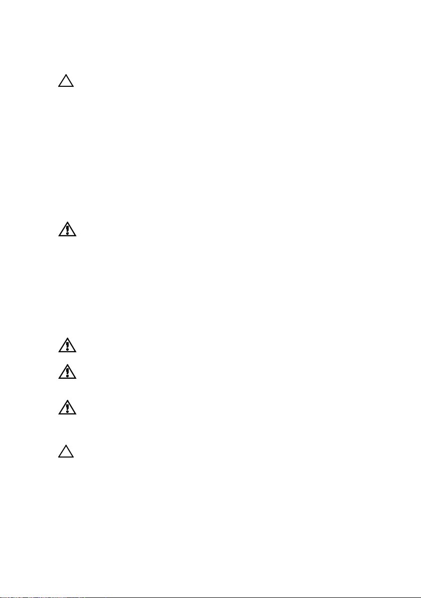
CAUTION: When installing rails in a square-hole rack it is important to
ensure that the square peg slides through the square holes.
Getting Started With Your System | 3
1
Pull on the latch release buttons on the midpoints of the end piece to
open the rail latches.
2
Align the end pieces of the rails on the vertical rack flanges to seat
the pegs in the bottom hole of the first U and the top hole of the
second U. Engage the back end of the rails until the latches lock in
place.
NOTE:
The rails can be used in both square-hole (item 1 in the following figure)
and round-hole racks (item 2 in the following figure).
Figure 1. Pushing the Latch Release Buttons
3
Repeat Step 1 and Step 2 to position and seat the front end pieces on
the vertical flanges.
NOTE:
To remove the rails, pull on the latch release button on the midpoints of
the end piece and unseat each rail.
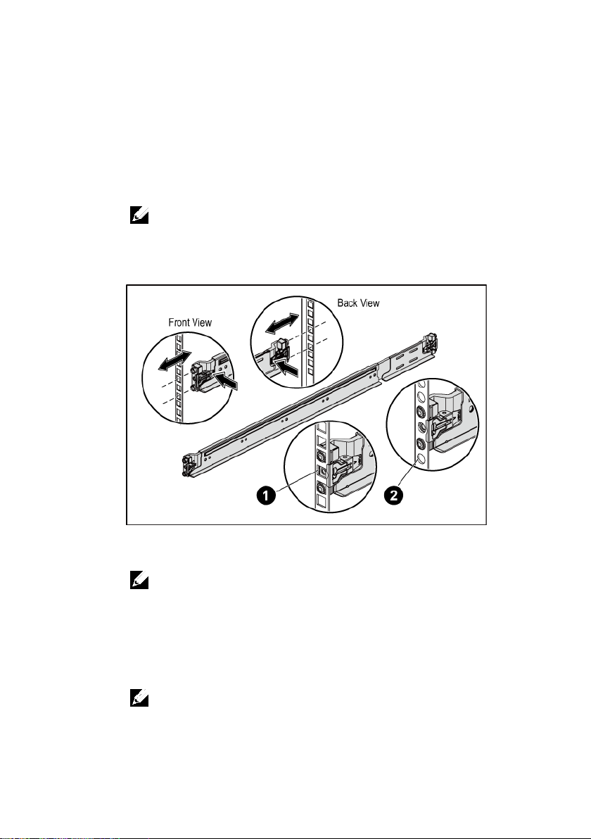
4
On each vertical rack flange on the back, put two screw bases into
the two square holes right above the rail.
5
Install the chassis stabilizer shipping brackets (optional) on the back
rack flanges and simultaneously tighten the screws.
NOTE:
To transport systems already installed in the rack, ensure that the two
chassis stabilizer shipping brackets (optional) are in place.
Getting Started With Your System | 4
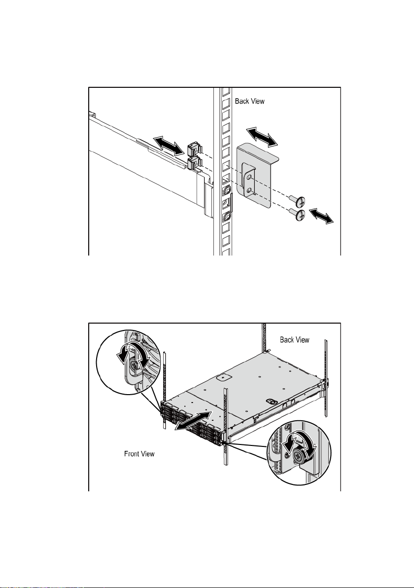
Figure 2. Installing the Chassis Stabilizer Shipping Brackets
6
Slide the system into the rack.
7
Tighten the thumbscrews to secure the ears of the system to the front
of the rack flanges.
Figure 3. Installing the Chassis onto the Rack.
Getting Started With Your System | 5
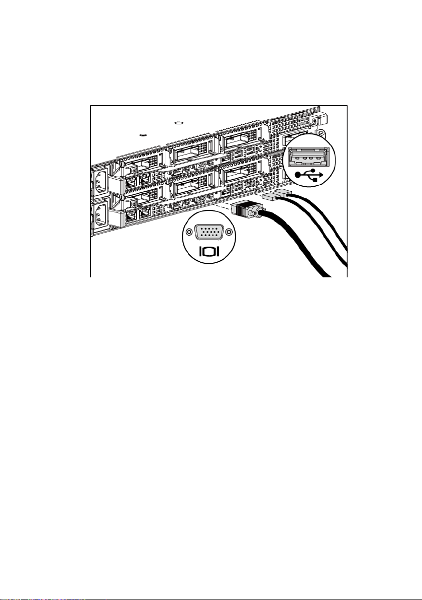
Optional—Connecting the Keyboard, Mouse, and Monitor
Figure 4. Optional—Connecting the Keyboard, Mouse and Monitor
Connect the keyboard, mouse, and monitor (optional).
The connectors on the back of your system have icons indicating which cable to
plug into each connector. Be sure to tighten the screws (if any) on the monitor’s
cable connector.
Getting Started With Your System | 6
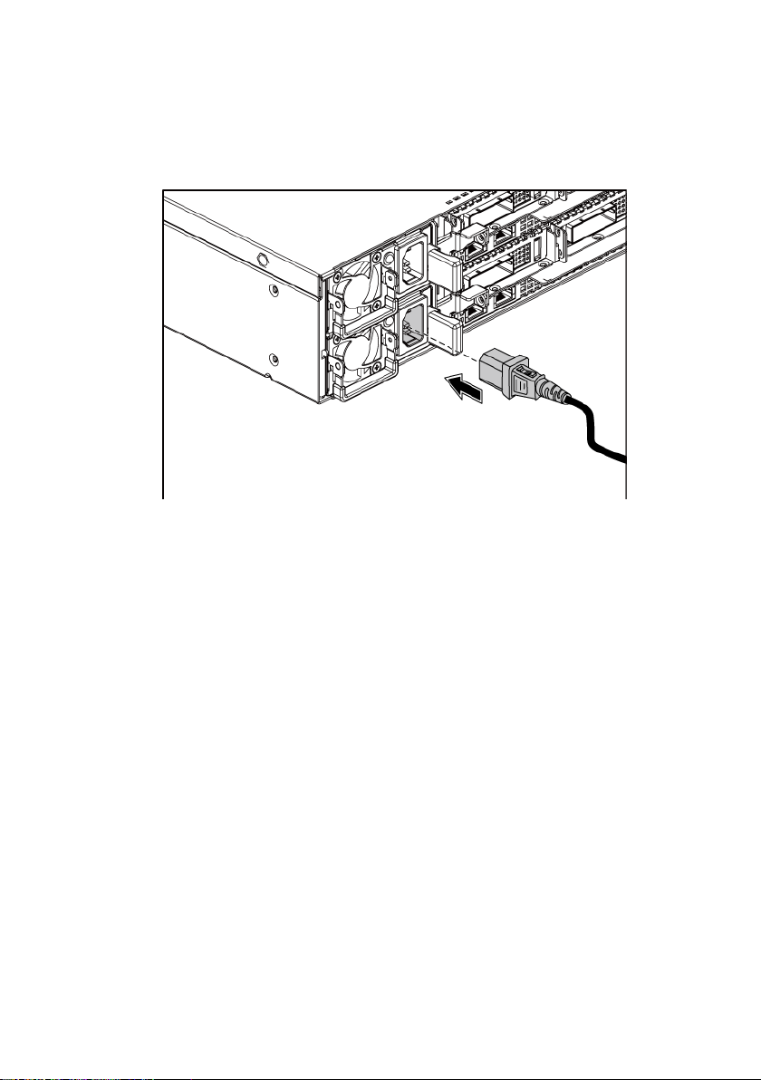
Connecting the Power Cable(s)
Figure 5. Connecting the Power Cable
Connect the system’s power cable(s) to the system and, if a monitor is used,
connect the monitor’s power cable to the monitor. Plug the other end of the
power cables into a grounded electrical outlet or a separate power source such as
an uninterrupted power supply or a power distribution unit.
Getting Started With Your System | 7
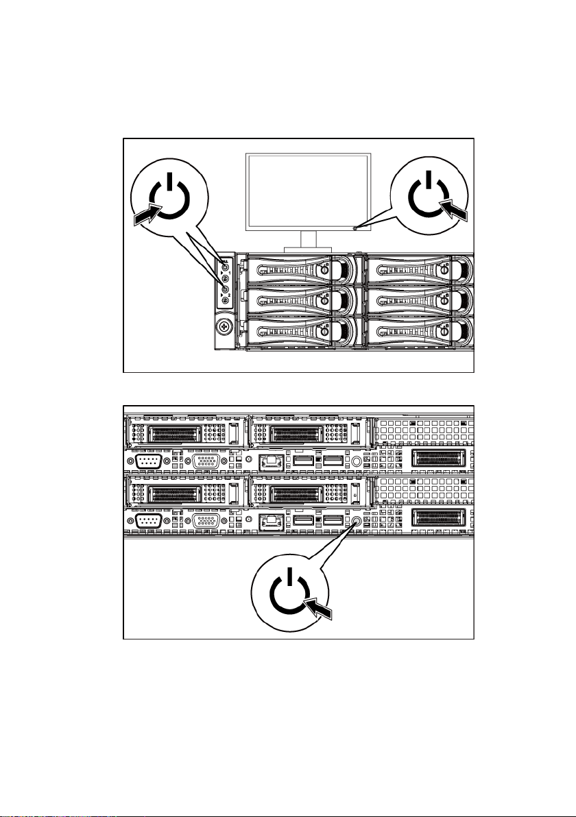
Turning on the System
Figure 6. Pressing the Power Button on the Front of the System and the Monitor
Figure 7. Pressing the Power Button on the Back of the System
Press the power button(s) either on the front or back of the system and on the
monitor. The power indicators on the front should light.
Getting Started With Your System | 8
NOTE:
The color of the power indicator on the monitor will vary with the different
monitor models.
Complete the Operating System Setup
To install an operating system for the first time, see the installation and
configuration documentation for your operating system. Be sure the operating
system is installed before installing hardware or software not purchased with the
system.
NOTE:
For the latest information on supported operating systems, see
dell.com/ossupport
.
Other Information You May Need
The Hardware Owner’s Manual provides information about system features and
describes how to troubleshoot the system and install or replace system
components. This document is available at
Dell systems management application documentation provides information
about installing and using the systems management software. This document is
available online at
WARNING: See the safety and regulatory information that shipped with your
system. Warranty information may be included within this document or as a
separate document.
dell.com/support/manuals
dell.com/support/manuals
NOTE:
Always check for updates on
updates first because they often supersede information in other documents.
dell.com/support/manuals
.
and read the
.
Getting Started With Your System | 9

Model number
B05S
Supply Unit
Unit
NOM Information (Mexico Only)
The following information is provided on the device described in this document
in compliance with the requirements of the official Mexican standards (NOM):
Importer Dell Inc. de México, S.A. de C.V.
Paseo de la Reforma 2620-11° Piso
Col. Lomas Atlas
11950 México, D.F.
Supply voltage 100-240 V CA with 1100 W Power
Supply Unit
200-240 V CA with 1400 W Power
Frequency 50/60 Hz
Current consumption
12-6.7 Amps with 1100 W Power
Supply Unit
8.6 Amps with 1400 W Power Supply
Getting Started With Your System | 10

Processor (Per System Board)
Expansion slots
or UDIMM
Minimum RAM
64 GB
Drives
Technical Specifications
Processor type Four AMD Opteron 6100 Series processors
Or four AMD Opteron 6200 Series
processors
Or four AMD Opteron 6300 Series
processors
Expansion Bus (Per System Board)
Bus type PCI Express Generation 2
PCIe One x16, low profile-MD1 (maximum length
4.795 inches)
Two x16, low profile-MD2 (maximum
length 6.674 inches)
Daughter card PCIe One x16, Mezzanine slot
Memory (Per System Board)
Architecture 32 x DDR3 1066/1333/1600 MHz RDIMM
Memory module sockets 32 x DDR3 DIMM sockets
Memory module capacities 2 GB, 4 GB, 8 GB, 16 GB, or 32GB
Maximum RAM 1024 GB
Hard drives Up to twelve 3.5-inch, hot-swappable
SAS/SATA drives or up to twenty four 2.5inch, hot-swappable SAS/SATA/SSD drives
NOTE: SAS hard drives are supported by
add-on card.
Getting Started With Your System | 11

Connectors (Per System Board)
NIC
Two RJ-45 (10/100/1000 Mbps Ethernet)
Serial
9-pin, DTE, 16550-compatible
Video
15-pin D-Sub VGA
bus extender port.
Internal
Micro-SD socket
SD riser card memory socket
Video (Per System Board)
Video type
On-board AST2050 video controller
Video memory
8 MB
Power
AC power supply (per power supply)
current: 12.0 Amps
Wattage
1400 W
Heat dissipation
5724 BTU/hr maximum
Back
USB Two 4-pin, USB 2.0-compliant
Management port Dedicated Ethernet port for remote
management access
iPass connector
Connect to external PCIE devices or a PCIE
Wattage 1023 W low line/1100 W high line
Voltage
100-240 VAC, 50-60 Hz, maximum input
Heat dissipation 4217.063 BTU/hr maximum
Voltage 200-240 VAC, 50-60 Hz, maximum input
Maximum inrush current Initial In-rush Current cannot exceed 55
Getting Started With Your System | 12
current: 8.6 Amps
Amps (peak). Secondary In-rush Current
cannot exceed 35 Amps (peak).

Battery (per system board)
RAID battery (optional)
3.7-V lithium ion battery pack
Physical
Height
8.76 cm (3.45 in)
Width
44.8 cm (17.6 in)
configuration)
Temperature
Relative humidity
hour
Maximum vibration
Operating
0.26 Grms at 5–350 Hz
System battery
CR 2032 3.0-V lithium ion coin cell
Depth 79.0 cm (31.1 in)
Weight (maximum
42 kg (92.61 lb)
Weight (empty) 16.5 kg (36.38 lb)
Environmental
NOTE:
For additional information about environmental measurements for specific system
configurations, see
www.dell.com/environmental_datasheets
.
Operating 10° to 35°C (50° to 95°F) with a maximum
temperature gradation of 10°C per hour
NOTE:
For altitudes above 2950 feet, the maximum
operating temperature is derated 1°F/550 ft.
NOTE:
For AMD 6180SE 140W processor, the maximum
operating temperature is up to 30°C (86°F)
Storage –40° to 65°C (–40° to 149°F) with a
maximum temperature gradation of 20°C per
hour
Operating 20% to 80% (noncondensing) with a
Storage 5% to 95% (noncondensing)
Storage 1.88 Grms at 10–500 Hz for 15 min
maximum humidity gradation of 10% per
Getting Started With Your System | 13

Maximum shock
centimeters/second)
Altitude
Storage
–16 to 10,600 m (–50 to 35,000 ft)
Airborne contaminant level
Class
G2 or lower as defined by ISA-S71.04-1985
Operating One shock pulse in the positive z axis
(one pulse on each side of the system) of 31
G for 2.6 ms in the operational orientation
Storage Six consecutively executed shock pulses in
the positive and negative x, y, and z axes
(one pulse on each side of the system) of 71
G for up to 2 ms;
Six consecutively executed shock pulses in
the positive and negative x, y, and z axes
(one pulse on each side of the system) of 22
G faired square wave pulse with velocity
change at 200 inches/second (508
Operating –16 to 3,048 m (–50 to 10,000 ft)
NOTE:
For altitudes above 2950 feet, the maximum
operating temperature is derated 1°F/550 ft.
Getting Started With Your System | 14

Dell PowerEdge
C6145
Guide de mise en route
du système
Remarques, précautions et avertissements
REMARQUE :
peuvent vous aider à mieux utiliser votre ordinateur.
PRÉCAUTION : une PRÉCAUTION indique un risque d'endommagement du
matériel ou de perte de données en cas de non respect des instructions.
AVERTISSEMENT : un AVERTISSEMENT indique un risque
d'endommagement du matériel, de blessure corporelle ou de mort.
une REMARQUE indique des informations importantes qui
______________
Les informations contenues dans ce document sont sujettes à modification
sans préavis.
© 2013 Dell Inc. tous droits réservés.
La reproduction de ce document de quelque manière que ce soit sans l'autorisation écrite
de Dell Inc. est strictement interdite.
Marques utilisées dans le présent document : Dell™, le logo DELL et PowerEdge™ sont
des marques de Dell Inc. AMD
marque d'Advanced Micro Devices, Inc. Red Hat Enterprise Linux
sont des marques déposées de Red Hat, Inc. aux États-Unis et/ou dans d'autres pays.
®
Novell
est une marque déposée et SUSE™ est une marque de Novell Inc. aux États-Unis
et dans d'autres pays. Citrix
Citrix Systems, Inc. aux États-Unis et/ou dans d'autres pays. VMware
déposée ou une marque de VMware, Inc. aux États-Unis ou dans d'autres pays.
D'autres marques et noms de marque peuvent être utilisés dans ce document pour faire
référence aux entités se réclamant de ces marques et de ces noms ou de leurs produits.
Dell Inc. rejette tout intérêt propriétaire dans les marques et les noms de marques autres
que les siens.
®
est une marque déposée et AMD Opteron™ est une
®
et XenServer® sont des marques déposées ou des marques de
®
et Enterprise Linux®
®
est une marque
Modèle réglementaire B05S
Septembre 2013 N/P 6HNH8 Rév. A04
PRÉCAUTION : lieux à accès restreint
Ce serveur est conçu pour être installé uniquement dans des zones à accès
restreint telles que définies par la consigne Cl. 1.2.7.3 de la norme
IEC 60950-1: 2001 où les deux conditions suivantes s'appliquent:
•
Seuls peuvent avoir accès le personnel d'entretien et les utilisateurs qui
ont été informés des motifs des restrictions appliquées au lieu et des
précautions à prendre.
•
L'accès, qui se fait par l'intermédiaire d'un outil ou d'un verrou et d'une clé,
ou par d'autres moyens de sécurité, est contrôlé par le responsable en
charge du lieu.
Installation et configuration
AVERTISSEMENT : avant de commencer la procédure suivante, lisez et
respectez les consignes de sécurité fournies avec le système.
Déballage du système
Sortez le système de son emballage et identifiez chaque élément.
Installation des rails sans outils
AVERTISSEMENT : demandez toujours de l'aide avant de soulever le
système. N'essayez pas de le soulever seul, car vous risqueriez de vous
blesser.
AVERTISSEMENT : le système n'est fixé ni au rack ni aux rails. Vous
devez le soutenir correctement au cours de l'installation et du retrait pour
éviter de l'endommager ou de vous blesser.
AVERTISSEMENT : afin d'éviter un éventuel choc électrique, assurez-vous
que vous disposez d'un troisième conducteur de mise à la terre pour
l'installation du rack. L'équipement du rack doit assurer une ventilation
suffisante pour bien refroidir le système.
PRÉCAUTION : lorsque vous installez des rails dans un rack à trous
carrés, vérifiez que les taquets de fixation à tête carrée glissent bien dans
les trous carrés.
Guide de mise en route du système | 17

1
Vue avan
t
Vue arrière
Tirez sur les boutons d'ouverture du loquet situés au milieu de l'unité
d'extrémité pour ouvrir les loquets des rails.
2
Alignez les extrémités des rails avec les montants verticaux du rack
de manière à insérer les chevilles, l'une en bas et l'autre en haut.
Faites glisser l'extrémité arrière des rails coulissants jusqu'à ce que
les loquets de verrouillage s'enclenchent.
REMARQUE : l
trous carrés (élément 1 dans la figure ci-dessous) que dans un rack à
trous ronds (élément 2 dans la figure ci-dessous).
Figure 1. Appui sur les boutons d'ouverture des loquets
3
Répétez l'étape 1 et l'étape 2 afin de positionner et fixer les embouts
es rails peuvent aussi bien être utilisés dans un rack à
avant des rails sur les montants verticaux.
REMARQUE :
loquet situé au milieu de l'unité d'extrémité et dégagez chaque rail.
4
À l'arrière de chaque montant vertical du rack, insérez deux vis dans
pour retirer les rails, tirez sur le bouton d'ouverture du
les deux trous carrés situés juste au-dessus du rail.
5
Installez les supports de stabilisation du châssis qui vous ont été
livrés (en option) sur les collerettes du rail arrière tout en serrant
les vis.
REMARQUE :
rack, assurez-vous que les deux supports d'expédition du stabilisateur de
châssis (en option) sont en place.
Guide de mise en route du système | 18
avant de transporter des systèmes déjà installés dans le
 Loading...