

Page 1

Dell™ Rack Installation Guide
Guide d'installation du rack Dell™
Dell™ Rack-Installationshandbuch
Dell™ ラック取り付けガイド
Guía de instalación del rack Dell™
Page 2

Page 3

Dell™ Rack Installation Guide
Page 4

Notes, Notices, and Cautions
NOTE: A NOTE indicates important information that helps you make better use
of your computer.
NOTICE: A NOTICE indicates either potential damage to hardware or loss of data
and tells you how to avoid the problem.
CAUTION: A CAUTION indicates a potential for property damage, personal injury,
or death.
____________________
Information in this document is subject to change without notice.
© 2007 Dell Inc. All rights reserved.
Reproduction in any manner whatsoever without the written permission of Dell Inc. is strictly
forbidden.
Trademarks used in this text: Dell, the DELL logo, RapidRails and VersaRails are trademarks of
Dell Inc.; Intel, Pentium and Celeron are registered trademarks of Intel Corporation; Microsoft and
Windows are either registered trademarks or trademarks of Microsoft Corporation in the United States
and/or other countries.
Other trademarks and trade names may be used in this document to refer to either the entities claiming
the marks and names or their products. Dell Inc. disclaims any proprietary interest in trademarks and
trade names other than its own.
November 2007 P/N TR669 Rev. A00
Page 5

Contents
Safety Instructions. . . . . . . . . . . . . . . . . . . . . 5
SAFETY: Rack Mounting of Systems
. . . . . . . . . 5
Installation Instructions
Before You Begin
Installation Tasks
Recommended Tools and Supplies
RapidRails Rack Kit Contents
VersaRails Rack Kit Contents
Marking the Rack
. . . . . . . . . . . . . . . . . . 6
. . . . . . . . . . . . . . . . . . . 7
. . . . . . . . . . . . . . . . . . . 8
. . . . . . . . . . 8
. . . . . . . . . . . . . 8
. . . . . . . . . . . . . 9
. . . . . . . . . . . . . . . . . . . . 11
Installing the RapidRails Slide Assemblies
Installing the VersaRails Slide Assemblies
Installing the System in the Rack
. . . . . . . . . . . . 17
Installing the Cable Tray
and Cable-Management Arm
. . . . . . . . . . . . . . 19
Attaching the Cable Tray to the System
Securing the Cable-Management Arm
Routing Cables
. . . . . . . . . . . . . . . . . . . . . . 21
. . . . . . . 13
. . . . . . . 15
. . . . . . 19
. . . . . . . 19
Contents 3
Page 6

4 Contents
Page 7

Safety Instructions
Use the following safety guidelines to ensure your own personal safety
and to help protect your system and working environment from potential
damage. For complete safety information, see the Product Information Guide.
SAFETY: Rack Mounting of Systems
Observe the following precautions for rack stability and safety.
Systems are considered to be components in a rack. Thus, “component”
refers to any system as well as to various peripherals or supporting hardware.
CAUTION: Before installing systems in a rack, install the front and side
stabilizers on stand-alone (single) racks or the front stabilizer on racks joined
to other racks. Failure to install stabilizers accordingly before installing systems
in a rack could cause the rack to tip over, potentially resulting in bodily injury
under certain circumstances. Therefore, always install the stabilizer(s) before
installing components in the rack.
CAUTION: After installing system/components in a rack, never pull more than one
component out of the rack on its slide assemblies at one time. The weight of more
than one extended component could cause the rack to tip over and cause injury.
NOTE: Your system is safety-certified as a free-standing unit and as a component
for use in a rack cabinet using the customer rack kit when both the rack cabinet
and rack kit were designed for your system. The installation of your system and rack
kit in any other rack cabinet has not been approved by any safety agencies. It is
your responsibility to have the final combination of system and rack kit in a cabinet
evaluated for suitability by a certified safety agency. The manufacturer disclaims
all warranties and liability in connection with such combinations.
• System rack kits are intended to be installed in an approved rack by
trained service technicians. If you install the kit in any other rack,
be sure that the rack meets the specifications.
• Before working on the rack, make sure that the stabilizers are secured
to the rack, extended to the floor, and that the full weight of the rack
rests on the floor. Install front and side stabilizers on a single rack or
front stabilizers for joined multiple racks before working on the rack.
• Always load the rack from the bottom up, and load the heaviest item
in the rack first.
Dell™ Rack Installation Guide 5
Page 8

• Make sure that the rack is level and stable before extending a component
from the rack.
• Use caution when pressing the component rail release latches and sliding
a component into or out of a rack; the slide rails can pinch your fingers.
• After a component is inserted into the rack, carefully extend the rail into
a locking position, and then slide the component into the rack.
• Do not overload the AC power supply branch circuit that provides power
to the rack. The total rack load should not exceed 80 percent of the branch
circuit rating.
• Ensure that proper airflow is provided to components in the rack.
• Do not step on or stand on any system/component when servicing other
systems/components in a rack.
Installation Instructions
This installation guide provides instructions for trained service technicians
installing one or more systems in an open-frame relay rack or in a rack
cabinet. The RapidRails™ rack kit can be installed without tools in
manufacturer’s rack cabinets that have square holes; the VersaRails™ rack
kit can be installed in most industry-standard rack cabinets that have square
or round holes. The procedures for installing both RapidRails and VersaRails
rack kits are similar. One rack kit is required for each system installed in the
rack.
CAUTION: Do not install rack kit components designed for another system.
Use only the rack kit for your system. Using the rack kit for another system
may result in damage to the system and personal injury.
The RapidRails rack kit can be installed in most industry-standard rack
cabinets.
NOTICE: The RapidRails rack kit is intended to be installed by trained service
technicians in a rack that meets the specifications of American National
Standards Institute (ANSI)/Electronic Industries Association (EIA) standard
ANSI/EIA-310-D-92, International Electrotechnical Commission (IEC) 297, and
Deutsche Industrie Norm (DIN) 41494. One rack kit is required for each system
that is installed in a rack.
6 Dell™ Rack Installation Guide
Page 9
Before You Begin
Before you begin installing your system in the rack, carefully read “Safety
Instructions”, found earlier in this guide, as well as the safety instructions
found in your Product Information Guide for additional information.
CAUTION: When installing multiple systems in a rack, complete all of the
procedures for the current system before attempting to install the next system.
CAUTION: Rack cabinets can be extremely heavy and move easily on the casters.
Use extreme caution while moving the rack cabinet. Retract the leveling feet
when relocating the rack cabinet. Avoid long or steep inclines or ramps where
loss of cabinet control may occur. Extend the leveling feet for support and to
prevent the cabinet from rolling.
Important Safety Information
Observe the safety precautions in the following subsections when installing
your system in the rack.
CAUTION: You must strictly follow the procedures in this document to protect
yourself as well as others who may be involved. Your system may be very large
and heavy, and proper preparation and planning are important to prevent injury
to yourself and to others. This becomes increasingly important when systems
are installed high up in the rack.
Rack Stabilizer Feet
CAUTION: Before installing systems in a rack, install the front and side
stabilizers on stand-alone (single) racks or the front stabilizer on racks joined
to other racks. Failure to install stabilizers accordingly before installing systems
in a rack could cause the rack to tip over, potentially resulting in bodily injury
under certain circumstances. Therefore, always install the stabilizer(s) before
installing components in the rack.
CAUTION: After installing systems in a rack, never pull more than one system
out of the rack on its slide assemblies at one time. The weight of more than
one extended system could cause the rack to tip over and cause injury.
The stabilizer feet help prevent the rack from tipping over when a system
or other component is pulled out of the rack with the slide assemblies
fully extended. See the documentation provided with the rack cabinet
for instructions on installing and anchoring the stabilizer feet.
Dell™ Rack Installation Guide 7
Page 10

Installation Tasks
Installing a rack kit involves performing the following tasks in their numbered
order:
1
Marking the rack (if necessary)
2
Installing the rail assemblies in the rack:
• RapidRails installation
• VersaRails installation
3
Installing the system in the rack
4
Installing the cable tray and cable-management arm
5
Routing cables
Recommended Tools and Supplies
• A #2 Phillips screwdriver
• Masking tape or a felt-tip pen, for use in marking the rack mounting holes
to be used
• A measuring ruler or tape measure
RapidRails Rack Kit Contents
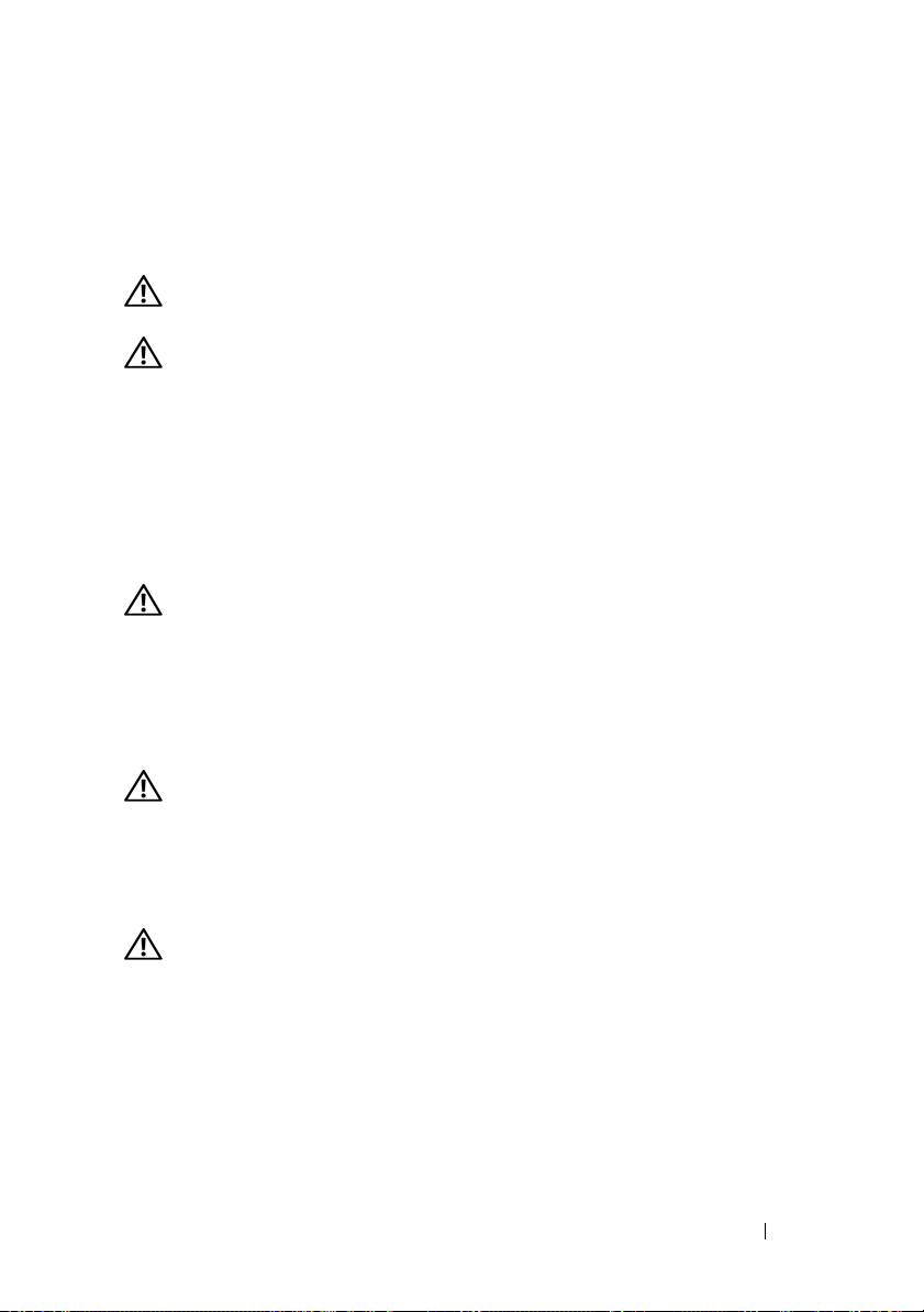
The RapidRails rack kit includes the following items (see Figure 1-1):
• One pair of RapidRails slide assemblies
• One cable-management arm
• One cable-management arm retainer
• One cable tray
• One status indicator cable (if applicable)
• One Velcro cable strap
8 Dell™ Rack Installation Guide
Page 11
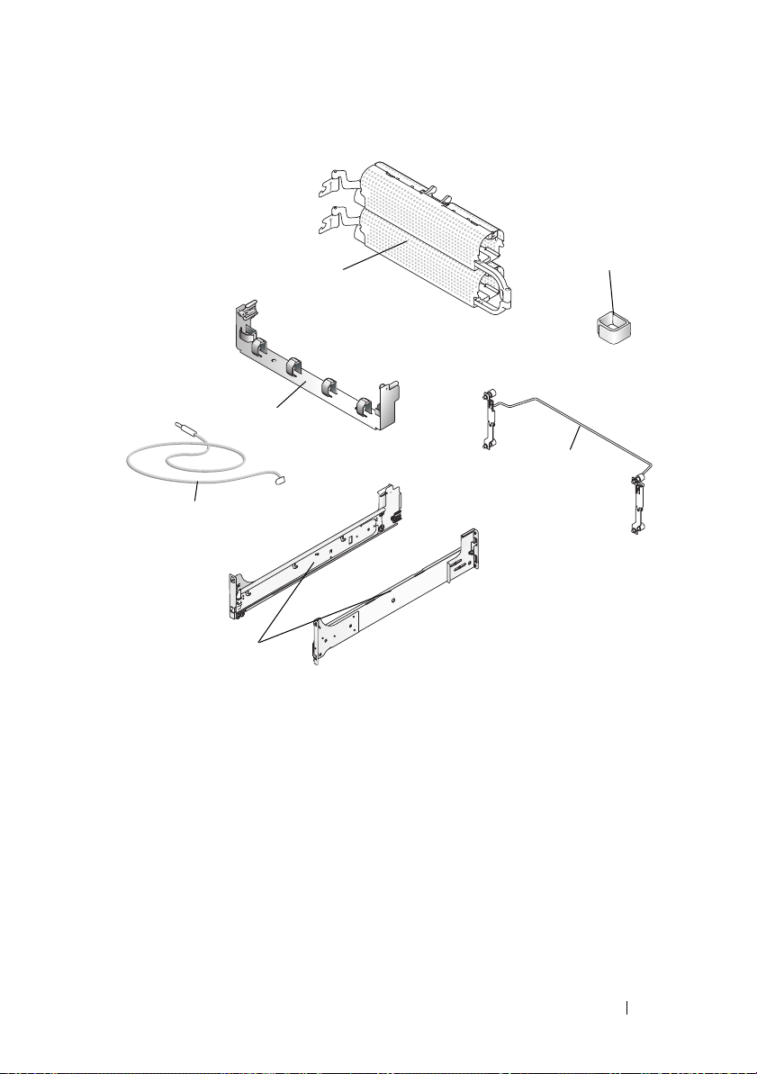
Figure 1-1. RapidRails Rack Kit Contents
1
3
5
6
1 cable-management arm 2 Velcro strap
3 cable tray 4 cable management arm retainer
5 status indicator cable (if applicable) 6 VersaRails slide assemblies
2
4
VersaRails Rack Kit Contents
The VersaRails rack kit includes the following items (see Figure 1-2):
• One pair of VersaRails slide assemblies
• One cable-management arm
• One cable-management arm retainer
• One cable tray
• One status indicator cable (if applicable)
Dell™ Rack Installation Guide 9
Page 12
• Eight 10-32 x 0.5-inch flange-head Phillips screws
• One Velcro cable strap
NOTE: The nonmetric screws described in illustrations and in procedural steps are
identified by size and number of threads per inch. For example, a #10 Phillips-head
screw with 32 threads per inch is identified as a 10-32 screw.
Figure 1-2. VersaRails Rack Kit Contents
1
3
4
5
2
6
7
1 cable-management arm 2 Velcro strap
3 cable tray 4 cable management arm retainer
5 status indicator cable (if applicable) 6 VersaRails slide assemblies
7 Ten 32 x 0.5 flange-head Phillips screws
10 Dell™ Rack Installation Guide
Page 13
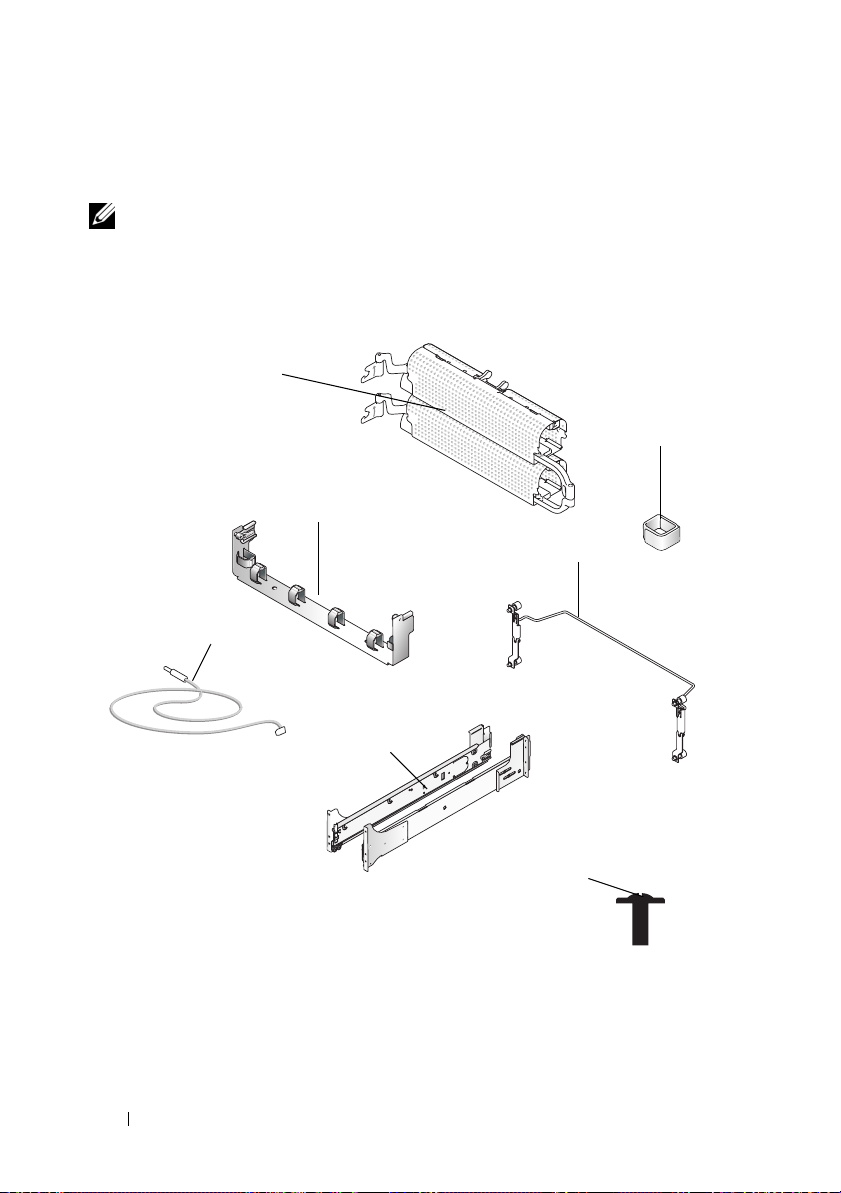
Marking the Rack
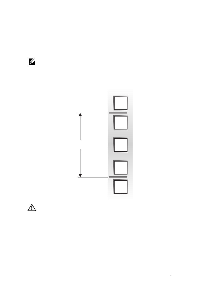
You must allow 4 U (7 inches) of vertical space for each system you install
in the rack (see Figure 1-3).
NOTE: Your rack may already be marked and not require this procedure.
Figure 1-3. One Rack Unit
12.7 mm (0.5 inch)
15.9 mm (0.625 inch)
1 U (44 mm or 1.75 inches)
15.9 mm (0.625 inch)
12.7 mm (0.5 inch)
CAUTION: If you are installing more than one system, install the slide assemblies
so that the first system is installed in the lowest available position in the rack.
To mark the rack, perform the following steps:
Place a mark on the rack’s front vertical rails where you want to locate
1
the bottom of the system you are installing in the rack cabinet.
The bottom of each 1-U space is at the middle of the narrowest metal
area between holes (marked with a horizontal line on some rack cabinets—
see Figure 1-4).
Dell™ Rack Installation Guide 11
Page 14

2
Place a mark approximately 7 inches above the original mark you made
(or count up 12 holes in a rack that meets EIA-310 standards) and mark
the rack’s front vertical rails with a felt-tipped pen or masking tape (if you
counted holes, place a mark just above the top hole). This mark or piece of
tape indicates where the system’s upper edge will be located on the vertical
rails (see Figure 1-4).
Figure 1-4. Marking the Vertical Rails
1
1 tape on vertical rail
12 Dell™ Rack Installation Guide
Page 15

Installing the RapidRails Slide Assemblies
1
At the front of the rack cabinet, position one of the RapidRails slide
assemblies so that its mounting-bracket flange fits in the appropriate
location on the rack (see Figure 1-5).
The top mounting hook on the rail assembly’s front-mounting bracket
flange should enter the top hole between the marks on the vertical rails.
2
Push the slide assembly forward until the top mounting hook enters the
square hole just below the upper marks or tape you placed on the vertical
rail. Next, push down on the mounting-bracket flange until the mounting
hooks seat in the square holes and the push button pops out and clicks
(see Figure 1-5).
3
At the back of the cabinet, pull back on the mounting-bracket flange
until the mounting hooks are in the appropriate holes, and then push
down on the flange until the mounting hooks seat in the square holes
and the push button pops out and clicks.
4
Repeat steps 1 through 3 for the slide assembly on the other side
of the rack.
NOTE: Ensure that the rails are mounted at the same vertical position
on both sides of the rack.
Dell™ Rack Installation Guide 13
Page 16
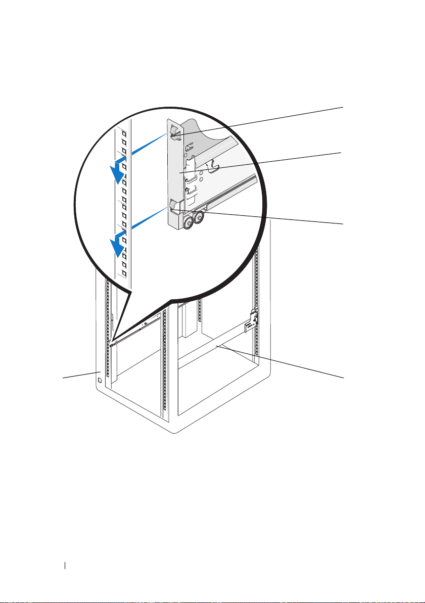
Figure 1-5. Installing the RapidRails Slide Assemblies
1
2
3
1 push button 2 slide-assembly mounting-bracket
flange
3 mounting hooks (2) 4 slide assemblies (2)
5 front of rack
14 Dell™ Rack Installation Guide
45
Page 17

Installing the VersaRails Slide Assemblies
1
At the front of the rack cabinet, place a VersaRails slide assembly so that
its mounting-bracket flange fits between the marks or tape (or numbered
location) on the rack (see Figure 1-6).
The holes on the front of the mounting bracket should align with the holes
between the marks on the front vertical rail.
2
Install a 10-32 x 0.5-inch flange-head Phillips screws in the mounting
flange’s top hole and the bottom hole (see Figure 1-6).
3
At the back of the cabinet, pull back on the mounting-bracket flange until
the mounting holes align with their respective holes on the back vertical
rail.
4
Install 10-32 x 0.5-inch flange-head Phillips screws in the second and third
holes (middle holes) of the back mounting flange to secure the slide
assembly to the back vertical rail.
NOTE: The top and bottom flange holes will be used later for installing the
cable-management arm retainer.
5
Repeat steps 1 through 4 for the slide assembly on the other side of the
rack.
NOTE: Ensure that the rails are mounted at the same vertical position on both
sides of the rack.
Dell™ Rack Installation Guide 15
Page 18
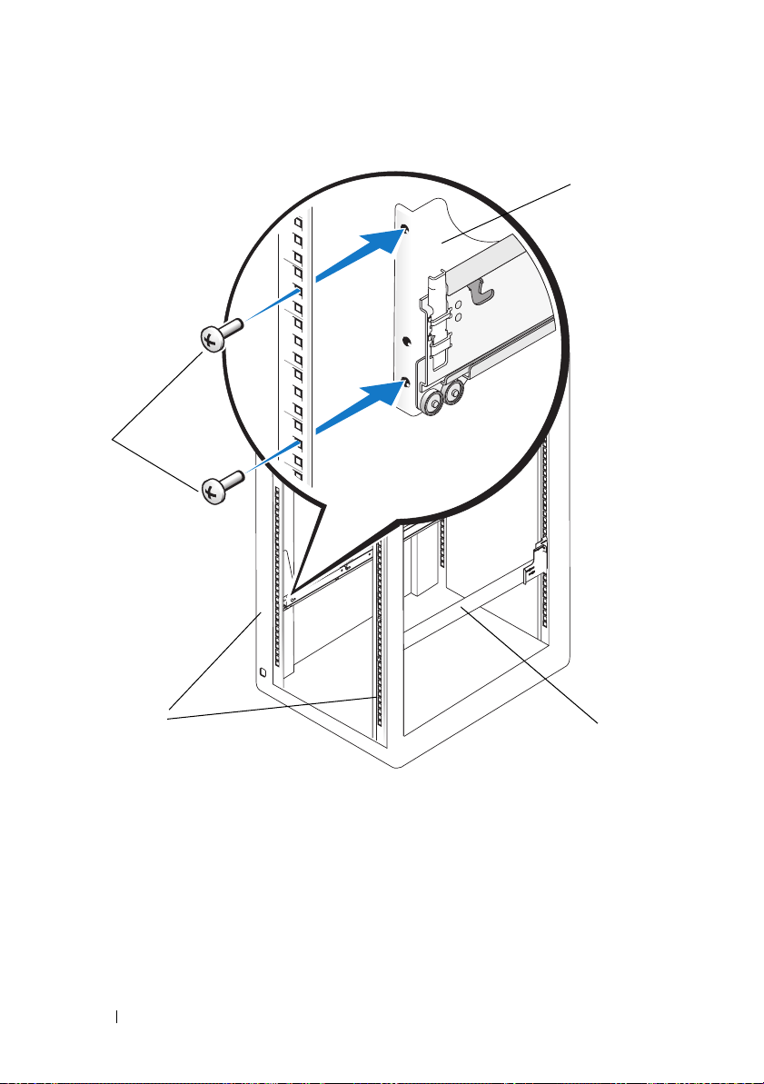
Figure 1-6. Installing the VersaRails Rail Assemblies
3
1
4
1 slide-assembly mounting-bracket
flange
3 flange-head Phillips screws (2) 4 front of rack
2 slide assemblies (2)
16 Dell™ Rack Installation Guide
2
Page 19

Installing the System in the Rack
CAUTION: If you are installing more than one system, install the first system
in the lowest available position in the rack.
CAUTION: Never pull more than one component out of the rack at a time.
1
Pull the two interior slide assemblies out of the rack until they lock
in the fully extended position.
CAUTION: Because of the size and weight of the system, never attempt
to install the system in the slide assemblies by yourself.
2
Lift the system into position.
Using a minimum of two persons, each person should place one hand on
the front-bottom of the system and the other hand on the back-bottom
of the system.
3
Tilt the front of the system upward while aligning the back shoulder
screws on the sides of the system with the back slots on the slide
assemblies (see Figure 1-7).
Dell™ Rack Installation Guide 17
Page 20
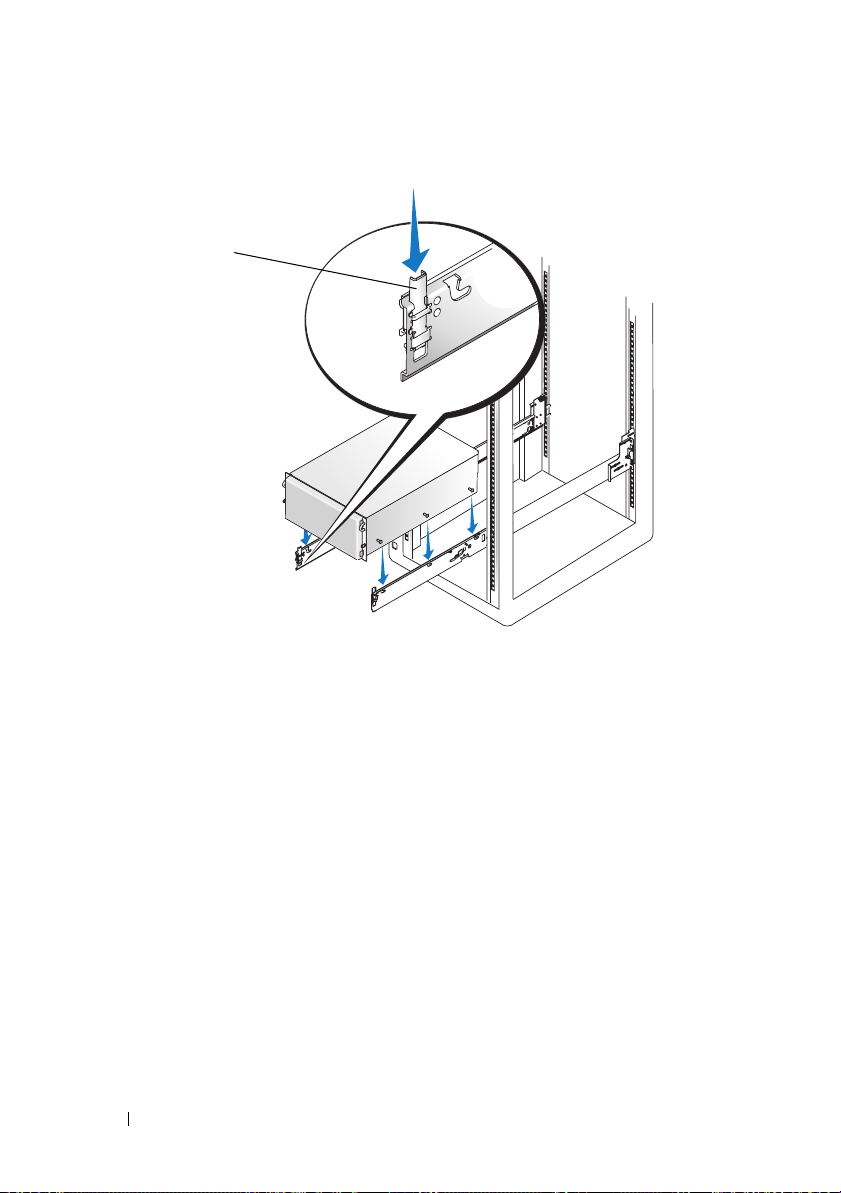
Figure 1-7. Installing the System in the Rack
1
1 system locking mechanism
4
Engage the back shoulder screws in the slot just behind the slide-release
latch, followed by the middle and front shoulder screws.
5
Push the system inward on the slide assemblies until the system-locking
mechanism clicks into place, locking the slide to the system
(see Figure 1-7).
6
Pull up on the slide-release latches and push the system into the rack.
7
Tighten the thumbscrews on the rack front panel.
18 Dell™ Rack Installation Guide
Page 21

Installing the Cable Tray and Cable-Management Arm
This procedure is performed in two phases. First, install the cable tray to
the back of the system chassis. Next, install the cable-management arm
on the cable tray.
Attaching the Cable Tray to the System
NOTE: Depending on the cable tray that ships with your rail kit, you will need
to follow the procedure for mounting the tray on the back of the system chassis.
Both cable trays are illustrated in Figure 1-8.
Mounting Type I
1
Align the formed metal tabs along the bottom of the cable tray with
the mating slots at the back of the system chassis.
2
Insert the tabs into the slots and rotate the tray downward to the secure
position (see Figure 1-8).
3
Secure the tray to the system with the two captive thumbscrews.
Mounting Type II
1
Align the formed metal tabs along the sides of the cable tray with the
bent metal notches on the inner walls at the back of the system chassis.
2
Slide the tabs over the metal notches and press the tray downward
to the secure position (see Figure 1-8).
3
Secure the tray to the system with the two captive thumbscrews.
CAUTION: The cable tray cannot support the weight of the system. Do not grasp
the cable tray when lifting the system. Lift the system only by the chassis edges.
Securing the Cable-Management Arm
NOTE: The cable-management arm can be installed on either side of the cable tray.
1
Facing the back of the rack cabinet, push the tab on the front end of the
cable-management arm into the latch on the cable tray until the latch
clicks (see Figure 1-8).
2
Push the tab on the unattached end of the cable-management arm into
the latch on the end of the slide assembly until the latch clicks.
Dell™ Rack Installation Guide 19
Page 22
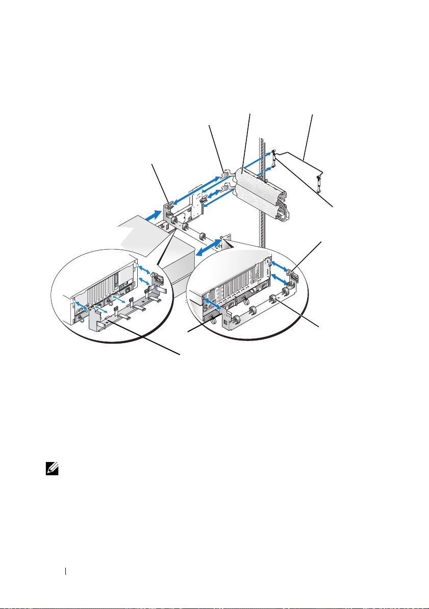
Figure 1-8. Installing the Cable-Management Arm
3
2
1
back of system
8
Mounting Type I
1 latch on cable tray 2 tabs
3 cable-management arm 4 cable-management retainer
5 captive thumbscrews (4) 6 captive thumbscrews (2)
7 Velcro strap 8 formed metal tabs
9 mounting tabs (2)
9
Mounting Type II
4
back of rack
6
7
5
NOTE: Figure 1-8 illustrates both rack rail types that demonstrate how to connect
the rack to your system.
20 Dell™ Rack Installation Guide
Page 23

Routing Cables
1
If applicable, install the system status-indicator cable plug into its
connector on the system back panel (see Figure 1-9).
2
Open both cable baskets on the cable-management arm by squeezing
the release latches on top of each basket.
The cable baskets swing open to enable cables to be routed within
the arms.
3
Route the system status-indicator cable along the cable-management
arm through the upper basket, and then, if desired, through the lower
basket. Insert the LED end into one of the indicator slots on the cablemanagement arm (see Figure 1-9).
Dell™ Rack Installation Guide 21
Page 24
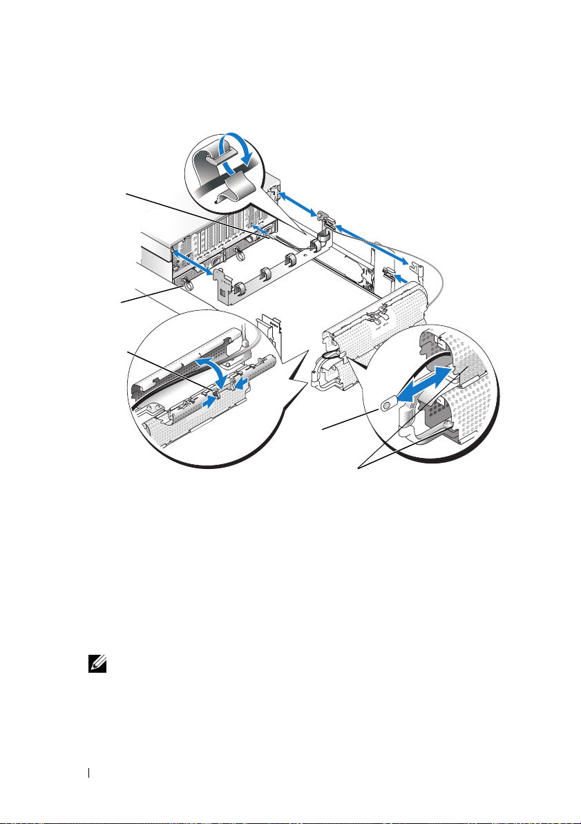
Figure 1-9. Installing the System Status Indicator Cable
1
2
3
4
5
1 system status indicator cable plug 2 strain-relief loops
(1 per power supply, if available)
3 release latch 4 system status indicator
5 system status indicator slot
4
Attach the I/O cable connectors and power cable connectors to their
respective connectors on the system back panel.
For details on cable connections, see your system’s
Troubleshooting Guide
NOTE: Use the strain-relief loops (if available) on the back of the power
supplies to provide strain relief for the power cables.
and the
User’s Guide
Installation and
.
22 Dell™ Rack Installation Guide
Page 25

5
Secure the cables to the horizontal surface of the cable tray using the
Velcro straps, then route the cables along the bend to where the cablemanagement arm attaches to the cable tray, and secure the cables with
the vertical Velcro strap (see Figure 1-10).
6
Route the cables along the cable-management arm through both cable
baskets, starting with the upper basket and exiting the lower basket
(see Figure 1-10).
7
Adjust the cable slack as needed at the hinge position.
8
Use the Velcro strap that ships with your system to tightly secure
the cable bundle to the cable basket elbow.
9
Close the cable baskets.
10
Unscrew the thumbscrews that secure the front of the system to the front
vertical rail.
Dell™ Rack Installation Guide 23
Page 26

Figure 1-10. Routing Cables on the Cable-Management Arm
1
2
1 cable tray Velcro strap (6) 2 CMA Velcro strap
24 Dell™ Rack Installation Guide
Page 27

11
Slide the system in and out of the rack to verify that the cables are routed
correctly and do not bind, stretch, or pinch with the movement of the
cable-management arm. Adjust the cable positioning inside the cable
baskets as needed.
NOTE: If you pull the system out to its furthest extension, the slide assemblies
will lock in the extended position. To release the lock, press the slide release
latch on the side of the slide and then slide the system into the rack.
12
Secure the cable-management arm retainer to the back of the rack using
the captive thumbscrews.
NOTE: Be sure to route the system cables under the retainer bar so
that the cables do not obstruct when the bar is opened or closed.
Dell™ Rack Installation Guide 25
Page 28

26 Dell™ Rack Installation Guide
Page 29

Guide d'installation
du rack Dell™
Page 30

Remarques, avis et précautions
REMARQUE : Une REMARQUE indique des informations importantes qui peuvent
vous aider à mieux utiliser votre ordinateur.
AVIS : Un AVIS vous avertit d'un risque de dommage matériel ou de perte
de données et vous indique comment éviter le problème.
PRÉCAUTION : Une PRÉCAUTION indique un risque potentiel d'endommagement
du matériel, de blessure corporelle ou de mort.
____________________
Les informations contenues dans ce document peuvent être modifiées sans préavis.
© 2007 Dell Inc. Tous droits réservés.
La reproduction de ce document de quelque manière que ce soit sans l'autorisation écrite de Dell Inc.
est strictement interdite.
Marques utilisées dans ce document : Dell, le logo DELL, RapidRails et VersaRails sont des marques
de Dell Inc. ; Intel, Pentium et Celeron sont des marques déposées de Intel Corporation ; Microsoft
et Windows sont des marques ou des marques déposées de Microsoft Corporation aux États-Unis
et/ou dans d'autres pays.
D'autres marques et noms de marques peuvent être utilisés dans ce document pour faire référence
aux entités se réclamant de ces marques et de ces noms ou à leurs produits. Dell Inc. dénie tout intérêt
propriétaire vis-à-vis des marques et des noms de marque autres que les siens.
Novembre 2007 N/P TR669 Rév. A00
Page 31

Table des matières
Consignes de sécurité . . . . . . . . . . . . . . . . . 31
SÉCURITÉ : montage en rack des systèmes
. . . . 31
Instructions d'installation
Avant de commencer
Tâches d'installation
. . . . . . . . . . . . . . . . 33
. . . . . . . . . . . . . . . 33
. . . . . . . . . . . . . . . . 34
Outils et fournitures recommandés
Contenu du kit RapidRails
Contenu du kit VersaRails
Marquage du rack
. . . . . . . . . . . . . . . . . . . 39
. . . . . . . . . . . . . 35
. . . . . . . . . . . . . 37
Installation des assemblages
à glissière RapidRails
. . . . . . . . . . . . . . . . . . 41
Installation des assemblages
à glissière VersaRails
. . . . . . . . . . . . . . . . . . 43
Installation du système dans le rack
Installation du chemin de câbles
et du bras de gestion des câbles
. . . . . . . . . . . . 47
Fixation du chemin de câbles sur le système
Fixation du bras de gestion des câbles
Acheminement des câbles
. . . . . . . . . . . . . . . 50
. . . . . . . . 35
. . . . . . . . . . 45
. . . 47
. . . . . . 48
Table des matières 29
Page 32

30 Table des matières
Page 33

Consignes de sécurité
Respectez les consignes de sécurité de ce guide pour assurer votre sécurité
personnelle et pour contribuer à protéger le système et l'environnement de
travail de dommages potentiels. Pour obtenir des informations complètes
concernant la sécurité, consultez le document Product Information Guide
(Guide d'information sur le produit).
SÉCURITÉ : montage en rack des systèmes
Pour garantir la stabilité du rack, ainsi que votre sécurité, respectez les
précautions suivantes.
Les systèmes sont considérés comme les composants d'un rack. Le terme
“composant” peut donc aussi bien désigner un système que les différents
périphériques ou matériels associés.
PRÉCAUTION : Avant d'installer des systèmes dans un rack autonome, installez
d'abord les pieds stabilisateurs avant et latéraux. Pour plusieurs racks associés,
installez d'abord les pieds stabilisateurs avant. L'installation de systèmes dans
un rack non équipé de pieds stabilisateurs peut provoquer son basculement et
entraîner des blessures dans certaines situations. Il est donc impératif d'installer
les pieds stabilisateurs du rack avant d'ajouter des composants dans celui-ci.
PRÉCAUTION : Après avoir installé un système ou des composants dans un rack,
ne faites jamais coulisser hors du rack plus d'un composant à la fois. Le poids de
plusieurs composants sortis du rack risquerait de le faire basculer et de provoquer
des blessures.
REMARQUE : Le système est certifié sur le plan de la sécurité en tant qu'unité
autonome et en tant que composant destiné à être utilisé dans une armoire rack
à l'aide du kit de rack client, à condition que l'armoire et le kit d'installation utilisés
aient été conçus pour ce système. L'installation du système et du kit d'installation
en rack dans une autre armoire n'a reçu aucune homologation des organismes
de certification de la sécurité. Il est de votre entière responsabilité de faire évaluer
par un organisme de sécurité agréé la combinaison finale formée par le système,
le kit d'installation et l'armoire rack. Le constructeur décline toute responsabilité
et garantie liée à ces combinaisons.
Guide d'installation du rack Dell™ 31
Page 34

• Les kits de rack sont conçus pour être installés par des techniciens
de maintenance qualifiés dans des racks homologués. Si vous installez
ce kit dans un autre rack, assurez-vous que ce dernier possède les
spécifications requises.
• Avant de travailler sur le rack, vérifiez que les pieds stabilisateurs sont
fixés au rack, qu'ils touchent le sol et que tout le poids du rack repose
sur le sol. Avant d'intervenir sur un rack autonome, installez d'abord
les pieds stabilisateurs avant et latéraux. Pour plusieurs racks associés,
installez d'abord les pieds stabilisateurs avant.
• Chargez le rack du bas vers le haut, en installant toujours l'élément
le plus lourd en premier.
• Assurez-vous que le rack est d'aplomb et stable avant de tirer un
composant hors de son compartiment.
• Agissez avec précaution lorsque vous appuyez sur les loquets de
dégagement des rails pour insérer ou retirer un composant. Veillez
notamment à ne pas coincer vos doigts dans les assemblages à glissière.
• Après avoir inséré un composant dans le rack, tirez doucement le rail
vers l'avant jusqu'au point de blocage, puis faites glisser le composant
dans le rack.
• Ne surchargez pas le circuit d'alimentation secteur du rack. La consommation totale du rack ne doit pas dépasser 80 % de la capacité du circuit.
• Assurez-vous que les éléments installés dans le rack disposent d'une
ventilation suffisante.
• Ne montez jamais sur un système ou composant lorsque vous intervenez
sur d'autres systèmes ou composants du rack.
32 Guide d'installation du rack Dell™
Page 35

Instructions d'installation
Ce guide d'installation s'adresse à des techniciens de maintenance qualifiés.
Il contient les instructions relatives à l'installation d'un ou de plusieurs
systèmes dans un rack à châssis ouvert ou une armoire rack. Le kit de rack
RapidRails™ peut être installé sans outils dans toutes les armoires racks
du constructeur dotées de trous carrés ; le kit VersaRails™ peut être installé
dans la plupart des armoires racks standard équipées de trous carrés ou ronds.
Les procédures permettant d'installer les kits RapidRails et VersaRails sont
similaires. Un kit de rack est nécessaire pour chaque système à installer.
PRÉCAUTION : N'installez pas de composants correspondant à un kit de rack
prévu pour un autre système. Utilisez uniquement le kit de rack conçu pour votre
système. Sinon, vous risquez d'endommager le système et de vous blesser ou de
blesser une autre personne.
Le kit de rack RapidRails peut être installé dans la plupart des armoires
rack standard.
AVIS : Le kit RapidRails est prévu pour être installé par des techniciens de
maintenance qualifiés dans un rack conforme aux spécifications des organismes
suivants : American National Standards Institute (ANSI)/Electronic Industries
Association (EIA) norme ANSI/EIA-310-D-92, International Electrotechnical
Commission (IEC) 297 et Deutsche Industrie Norm (DIN) 41494. Vous devez
utiliser un kit pour chaque système installé dans le rack.
Avant de commencer
Avant de commencer à installer le système dans le rack, lisez attentivement
la section “Consignes de sécurité” au début de ce document, ainsi que
les consignes de sécurité figurant dans le document Product Information
Guide (Guide d'information sur le produit) pour plus d'informations.
PRÉCAUTION : Si vous installez plusieurs systèmes dans un rack, terminez
toutes les opérations requises sur le système en cours d'installation avant de
passer au suivant.
PRÉCAUTION : Les armoires racks peuvent être extrêmement lourdes, mais
les roulettes permettent de les déplacer facilement. Procédez avec la plus grande
prudence pour déplacer une armoire rack. Rentrez ses pieds réglables lorsque
vous la changez d'emplacement. Évitez de déplacer l'armoire rack le long de
rampes ou de plans inclinés trop longs ou trop abrupts, sur lesquels elle pourrait
vous échapper. Ressortez les pieds réglables lorsque l'armoire doit être soutenue
et pour lui éviter de se déplacer sur ses roulettes.
Guide d'installation du rack Dell™ 33
Page 36

Informations importantes concernant la sécurité
Respectez les consignes de sécurité décrites dans les sous-sections suivantes
lors de l'installation du système dans le rack.
PRÉCAUTION : Vous devez respecter à la lettre les procédures de ce document
afin de garantir votre propre protection ainsi que celle d'autrui. Le système peut
être très lourd et volumineux. Une préparation et une planification adéquates sont
donc importantes afin d'éviter tout risque de blessure pour vous-même ou autrui.
Ces précautions sont d'autant plus importantes lorsque les systèmes sont installés
en hauteur.
Pieds stabilisateurs du rack
PRÉCAUTION : Avant d'installer des systèmes dans un rack autonome, installez
d'abord les pieds stabilisateurs avant et latéraux. Pour plusieurs racks associés,
installez d'abord les pieds stabilisateurs avant. L'installation de systèmes dans
un rack non équipé de pieds stabilisateurs peut provoquer son basculement et
entraîner des blessures dans certaines situations. Installez toujours les pieds
stabilisateurs avant d'ajouter des composants dans le rack.
PRÉCAUTION : Après avoir installé des systèmes dans un rack, ne faites
jamais coulisser hors du rack plus d'un système à la fois. Le poids de plusieurs
systèmes sortis du rack risquerait de le faire basculer et de blesser quelqu'un.
Les pieds stabilisateurs évitent au rack de basculer lorsque vous étendez les
assemblages à glissière au maximum pour tirer un système ou un composant
hors du rack. Consultez la documentation fournie avec l'armoire rack pour
savoir comment installer et fixer les pieds stabilisateurs.
Tâches d'installation
Pour installer un kit, vous devez effectuer les tâches suivantes dans l'ordre
indiqué :
1
Marquage du rack (si nécessaire)
2
Installation des assemblages de rails dans le rack
• Installation du kit RapidRails
• Installation du kit VersaRails
3
Installation du système dans le rack
4
Installation du chemin de câbles et du bras de gestion des câbles
5
Acheminement des câbles
34 Guide d'installation du rack Dell™
Page 37

Outils et fournitures recommandés
• Tournevis cruciforme n° 2
• Bande adhésive ou stylo feutre, pour marquer les orifices de montage
à utiliser
• Règle ou mètre-ruban
Contenu du kit RapidRails
Le kit RapidRails comprend les éléments suivants (voir Figure 1-1) :
• Une paire d'assemblages à glissière RapidRails
• Un bras de gestion des câbles
• Une tige de retenue pour le bras de gestion des câbles
• Un chemin de câbles
• Un câble de voyant d'état (si nécessaire)
• Une bande Velcro
Guide d'installation du rack Dell™ 35
Page 38

Figure 1-1. Contenu du kit RapidRails
1
3
5
6
1 Bras de gestion des câbles 2 Bande Velcro
3 Chemin de câbles 4 Tige de retenue
5 Câble de voyant d'état
(si nécessaire)
6 Assemblages à glissière RapidRails
2
4
36 Guide d'installation du rack Dell™
Page 39

Contenu du kit VersaRails
Le kit VersaRails comprend les éléments suivants (voir Figure 1-2) :
• Une paire d'assemblages à glissière VersaRails
• Un bras de gestion des câbles
• Une tige de retenue pour le bras de gestion des câbles
• Un chemin de câbles
• Un câble de voyant d'état (si nécessaire)
• Huit vis cruciformes à tête plate 10-32 x 0,5 pouce
• Une bande Velcro
REMARQUE : Les vis non métriques décrites dans les illustrations et les
instructions sont identifiées en fonction de leur taille et de leur nombre de filets
par pouce. Par exemple, une vis cruciforme n° 10 avec 32 filets par pouce est
appelée “vis 10-32”.
Guide d'installation du rack Dell™ 37
Page 40

Figure 1-2. Contenu du kit VersaRails
1
3
5
2
4
6
7
1 Bras de gestion des câbles 2 Bande Velcro
3 Chemin de câbles 4 Tige de retenue
5 Câble de voyant d'état
(si nécessaire)
7 Dix vis cruciformes à tête plate 32 x 0,5 pouce
6 Assemblages à glissière
VersaRails
38 Guide d'installation du rack Dell™
Page 41

Marquage du rack
Vous devez compter un espace vertical de 4 U (7 pouces, soit 17,78 cm)
pour chaque système à installer dans le rack (voir Figure 1-3).
REMARQUE : Il se peut que votre rack soit déjà marqué, auquel cas cette
procédure est inutile.
Figure 1-3. Unité de rack
12,7 mm (0,5 pouce)
15,9 mm (0,625 pouce)
1 U (44 mm, soit 1,75 pouces)
15,9 mm (0,625 pouce)
12,7 mm (0,5 pouce)
PRÉCAUTION : Si vous installez plusieurs systèmes, placez les assemblages
à glissière de façon que le premier système soit installé le plus bas possible
dans le rack.
Pour marquer le rack, procédez comme suit :
1
Placez une marque sur les rails verticaux avant du rack, à l'endroit où
vous souhaitez placer le bas du système à installer dans l'armoire rack.
Le bas de chaque espace de 1 U se trouve au milieu de la zone métallique
la plus étroite entre les trous (repérée par une ligne horizontale sur
certaines armoires racks ; voir Figure 1-4).
Guide d'installation du rack Dell™ 39
Page 42

2
Placez une marque à 17,78 centimètres (7 pouces) au-dessus de la marque
que vous avez faite au départ (ou remontez de 12 trous dans les racks
conformes à la norme EIA-310), puis marquez les rails verticaux avant du
rack avec un stylo feutre ou de la bande adhésive. Si vous avez compté les
trous, placez une marque juste au-dessus du trou supérieur. Cette marque
ou ce morceau de bande adhésive indique la position future du haut du
système sur les rails verticaux (voir Figure 1-4).
Figure 1-4. Marquage des rails verticaux
1
1 Bande apposée sur le rail vertical
40 Guide d'installation du rack Dell™
Page 43

Installation des assemblages à glissière RapidRails
1
À l'avant de l'armoire rack, positionnez l'un des assemblages à glissière
RapidRails de façon que la collerette de son support de montage s'insère
à l'endroit approprié sur le rack (voir Figure 1-5).
Le crochet de fixation supérieur situé sur la collerette avant du support
de montage doit pénétrer dans le trou du haut, entre les marques faites
sur les rails verticaux.
2
Poussez l'assemblage à glissière vers l'avant jusqu'à ce que le crochet de
montage supérieur pénètre dans le trou carré approprié, juste en dessous
des marques (ou du morceau de bande adhésive) placées sur le rail vertical.
Ensuite, appuyez sur la collerette jusqu'à ce que les crochets de montage
s'emboîtent dans les trous carrés et que le bouton-poussoir ressorte avec un
déclic (voir Figure 1-5).
3
À l'arrière de l'armoire, tirez la collerette de montage vers l'arrière jusqu'à
ce que les crochets s'insèrent dans les trous appropriés, puis appuyez sur
la collerette jusqu'à ce que ces crochets s'emboîtent dans les trous carrés
et que le bouton-poussoir ressorte avec un déclic.
4
Recommencez les étapes 1 à 3 pour installer le second assemblage
à glissière de l'autre côté du rack.
REMARQUE : Vérifiez que les rails sont montés à la même hauteur
des deux côtés du rack.
Guide d'installation du rack Dell™ 41
Page 44

Figure 1-5. Installation des assemblages à glissière RapidRails
1
2
3
1 Bouton poussoir 2 Collerette du support de montage
de l'assemblage à glissière
3 Crochets de montage (2) 4 Assemblages à glissière (2)
5 Avant du rack
42 Guide d'installation du rack Dell™
45
Page 45

Installation des assemblages à glissière VersaRails
1
À l'avant de l'armoire rack, positionnez l'un des assemblages à glissière
VersaRails de façon que la collerette de son support de montage s'insère
entre les marques ou la bande adhésive (ou l'emplacement numéroté)
sur le rack (voir Figure 1-6).
Les trous situés à l'avant du support de montage doivent s'aligner avec
ceux qui se trouvent entre les marques faites sur le rail vertical avant.
2
Insérez une vis cruciforme à tête plate 10-32 x 0,5 pouce dans les
trous supérieur et inférieur de la collerette du support de montage
(voir Figure 1-6).
3
À l'arrière de l'armoire, tirez la collerette de montage vers l'arrière jusqu'à
ce que les trous de montage s'alignent avec les trous correspondants du
rail vertical arrière.
4
Insérez une vis cruciforme à tête plate 10-32 x 0,5 pouce dans le deuxième
et le troisième trou (orifices centraux) de la collerette de montage arrière,
afin de fixer l'assemblage à glissière sur le rail vertical arrière.
REMARQUE : Le trou du haut et celui du bas de la collerette seront ensuite
utilisés pour installer la tige de retenue du bras de gestion des câbles.
5
Recommencez les étapes 1 à 4 pour installer le second assemblage
à glissière de l'autre côté du rack.
REMARQUE : Vérifiez que les rails sont montés à la même hauteur
des deux côtés du rack.
Guide d'installation du rack Dell™ 43
Page 46

Figure 1-6. Installation des assemblages à glissière VersaRails
3
1
4
1 Collerette du support de montage
de l'assemblage à glissière
3 Vis cruciformes à tête plate (2) 4 Avant du rack
2 Assemblages à glissière (2)
44 Guide d'installation du rack Dell™
2
Page 47

Installation du système dans le rack
PRÉCAUTION : Si vous installez plusieurs systèmes, installez le premier
le plus bas possible dans le rack.
PRÉCAUTION : Ne tirez jamais plusieurs composants hors du rack en même
temps.
1
Tirez les deux assemblages à glissière internes hors du rack jusqu'à
ce qu'ils se bloquent.
PRÉCAUTION : La taille et le poids du système sont importants ; n'essayez jamais
d'installer ce dernier dans les assemblages à glissière sans vous faire aider.
2
Soulevez le système et placez-le dans la bonne position.
L'opération doit être réalisée par au moins deux personnes. Chaque
personne doit placer une main sous l'avant du système, et l'autre sous
l'arrière du système.
3
Inclinez l'avant du système vers le haut tout en faisant correspondre les
vis à épaulement arrière, sur les côtés du système, avec les fentes situées
à l'arrière des assemblages à glissière (voir Figure 1-7).
Guide d'installation du rack Dell™ 45
Page 48

Figure 1-7. Installation du système dans le rack
1
1 Mécanisme de verrouillage du système
4
Engagez la vis à épaulement arrière dans la fente située juste derrière
le loquet de dégagement de la glissière, puis engagez la vis centrale et
celle située à l'avant.
5
Poussez le système vers l'intérieur sur les assemblages à glissière jusqu'à
ce que le mécanisme s'enclenche et verrouille la glissière sur le système.
Voir Figure 1-7.
6
Tirez les loquets de dégagement vers le haut et poussez le système
dans le rack.
7
Serrez les vis moletées sur le panneau avant du rack.
46 Guide d'installation du rack Dell™
Page 49

Installation du chemin de câbles et du bras de gestion des câbles
Cette procédure comprend deux étapes. Vous devez d'abord installer
le chemin de câbles à l'arrière du châssis du système, puis fixer le bras
de gestion des câbles sur le chemin de câbles.
Fixation du chemin de câbles sur le système
REMARQUE : La procédure à utiliser pour fixer le chemin de câbles à l'arrière
du système varie en fonction du modèle qui vous a été fourni avec le kit de rails.
Les deux chemins de câbles sont représentés Figure 1-8.
Montage du type I
1
Alignez les pattes métalliques situées au bas du chemin de câbles
avec les fentes correspondantes, à l'arrière du châssis du système.
2
Insérez les pattes dans les fentes et faites pivoter le chemin de câbles
vers le bas pour le mettre en place (voir Figure 1-8).
3
Fixez le chemin de câbles au système à l'aide des deux vis moletées
imperdables.
Guide d'installation du rack Dell™ 47
Page 50

Montage du type II
1
Alignez les pattes métalliques situées sur les côtés du chemin de câbles
avec les encoches recourbées situées sur les parois internes, à l'arrière
du châssis du système.
2
Glissez les pattes métalliques sur les encoches et appuyez sur le chemin
de câbles pour le mettre en place (voir Figure 1-8).
3
Fixez le chemin de câbles au système à l'aide des deux vis moletées
imperdables.
PRÉCAUTION : Le chemin de câbles n'est pas conçu pour supporter le poids
du système. Ne l'utilisez pas pour soulever ce dernier. Pour soulever le système,
saisissez uniquement les bords du châssis.
Fixation du bras de gestion des câbles
REMARQUE : Le bras de gestion des câbles peut être installé des deux côtés
du chemin de câbles.
1
Placez-vous derrière l'armoire rack. Enfoncez la patte située à l'avant du
bras de gestion des câbles dans le loquet du chemin de câbles, jusqu'à ce
que vous sentiez un déclic (voir Figure 1-8).
2
Enfoncez la patte qui se trouve à l'extrémité non fixée du bras de gestion
des câbles dans le loquet situé au bout de l'assemblage à glissière, jusqu'à
ce que vous sentiez un déclic.
48 Guide d'installation du rack Dell™
Page 51

Figure 1-8. Installation du bras de gestion des câbles
3
2
1
Arrière
du système
8
Montage du type I
1 Loquet du chemin de câbles 2 Pattes
3 Bras de gestion des câbles 4 Tige de retenue
5 Vis moletées imperdables (4) 6 Vis moletées imperdables (2)
7 Bande Velcro 8 Pattes métalliques
9 Pattes de montage (2)
9
Montage du type II
4
Arrière
du rack
6
7
5
REMARQUE : La figure 1-8 présente les deux types de rails permettant
de connecter le rack au système.
Guide d'installation du rack Dell™ 49
Page 52

Acheminement des câbles
1
Le cas échéant, insérez la fiche du câble du voyant d'état du système
dans le connecteur approprié, sur le panneau arrière du système
(voir Figure 1-9).
2
Ouvrez chaque conduit du bras de gestion des câbles en appuyant
sur les loquets de dégagement prévus à cet effet.
Les conduits s'ouvrent pour permettre la mise en place des câbles.
3
Acheminez le câble du voyant d'état dans le bras de gestion des câbles,
en commençant par le conduit supérieur et en terminant éventuellement
par le conduit inférieur. Insérez l'extrémité dotée du voyant dans l'un
des emplacements appropriés, sur le bras de gestion des câbles
(voir Figure 1-9).
50 Guide d'installation du rack Dell™
Page 53

Figure 1-9. Installation du câble du voyant d'état du système
1
2
3
4
5
1 Fiche du câble du voyant d'état
du système
3 Loquet de dégagement 4 Voyant d'état du système
5 Connecteur du voyant d'état
du système
2 Boucles (une par bloc d'alimentation,
le cas échéant)
Guide d'installation du rack Dell™ 51
Page 54

4
Branchez les câbles d'E/S et les câbles d'alimentation sur les connecteurs
correspondants, à l'arrière du système.
Pour plus d'informations sur la connexion des câbles, reportez-vous aux
documents
et de dépannage) et
Installation and Troubleshooting Guide
User's Guide
(Guide d'utilisation) fournis avec
(Guide d'installation
le système.
REMARQUE : Pour éviter une tension excessive des câbles d'alimentation,
faites-les passer dans les boucles situées à l'arrière des blocs d'alimentation,
le cas échéant.
5
Utilisez les bandes Velcro pour attacher les câbles sur la surface
horizontale du chemin de câbles. Acheminez les câbles pour les faire
passer à l'endroit où le bras de gestion est fixé sur le chemin de câbles.
Fixez-les ensuite à l'aide de la bande Velcro verticale (voir Figure 1-10).
6
Faites passer les câbles dans les deux conduits du bras de gestion
des câbles, en commençant par celui du haut (voir Figure 1-10).
7
Réglez la tension des câbles pour qu'il y ait suffisamment de jeu
au niveau de la charnière.
8
Utilisez la bande Velcro fournie avec le système pour attacher
le faisceau de câbles au niveau du coude du conduit de câbles.
9
Refermez les conduits de câbles.
10
Desserrez les vis moletées fixant l'avant du système au rail vertical avant.
52 Guide d'installation du rack Dell™
Page 55

Figure 1-10. Acheminement des câbles dans le bras de gestion des câbles
1
1 Bande Velcro du chemin
de câbles (6)
2
2 Bande Velcro du bras
de gestion des câbles
Guide d'installation du rack Dell™ 53
Page 56

11
Poussez le système dans le rack puis ressortez-le, pour vérifier que
les câbles sont installés correctement. Ils ne doivent pas se bloquer,
se tendre ni se coincer lorsque le bras de gestion des câbles se déplace.
Réajustez la position les câbles dans les conduits, si nécessaire.
REMARQUE : Si vous tirez le système complètement hors du rack,
les assemblages à glissière se verrouillent dans cette position.
Pour les déverrouiller, appuyez sur le loquet de dégagement situé
sur le côté de la glissière, puis faites coulisser le système dans le rack.
12
Fixez la tige de retenue du bras de gestion des câbles sur l'arrière du rack,
à l'aide des vis moletées imperdables.
REMARQUE : Vérifiez que les câbles du système passent sous la tige
de retenue et n'entravent pas sa course.
54 Guide d'installation du rack Dell™
Page 57

Dell™ Rack-
Installationshandbuch
Page 58

Anmerkungen, Hinweise und Vorsichtshinweise
ANMERKUNG: Eine ANMERKUNG macht auf wichtige Informationen
aufmerksam, die Ihnen die Arbeit mit dem Computer erleichtern.
HINWEIS: Ein HINWEIS zeigt entweder potenziellen Schaden an der Hardware
oder Verlust von Daten an und zeigt Ihnen, wie man das Problem vermeidet.
VORSICHT: Hiermit werden Sie auf eine potentiell gefährliche Situation
hingewiesen, die zu Sachschäden, Verletzungen oder zum Tod von Menschen
führen könnte.
____________________
Irrtümer und technische Änderungen vorbehalten.
© 2007 Dell Inc. Alle Rechte vorbehalten.
Nachdrucke jeglicher Art ohne die vorherige schriftliche Genehmigung von Dell Inc. sind strengstens
untersagt.
Marken in diesem Text: Dell, das DELL Logo, RapidRails und VersaRails sind Marken von Dell Inc.;
Intel, Pentium und Celeron sind eingetragene Marken von Intel Corporation; Microsoft und Windows
sind Marken oder eingetragene Marken von Microsoft Corporation in den USA und/oder anderen
Ländern.
Alle anderen in dieser Dokumentation genannten Marken und Handelsbezeichnungen sind Eigentum
der entsprechenden Hersteller und Firmen. Dell Inc. verzichtet auf alle Besitzrechte an Marken und
Handelsbezeichnungen, die nicht ihr Eigentum sind.
November 2007 Teilenr. TR669 Rev. A00
Page 59

Inhalt
Sicherheitshinweise . . . . . . . . . . . . . . . . . . 59
SICHERHEIT: Systeme im Rack montieren
. . . . . 59
Installationsanleitung
Vorbereitungen
Ablauf der Installation
Empfohlene Werkzeuge und Zubehör
Inhalt des RapidRails-Rack-Kits
Inhalt des VersaRails-Rack-Kits
Markieren des Racks
Einbauen der RapidRails-Laufschienen
Einbauen der VersaRails-Laufschienen
Installation des Systems im Rack
Einbau der Kabelablage und des Kabelarms
Kabelablage am System befestigen
Kabelführungsarm befestigen
. . . . . . . . . . . . . . . . . . 61
. . . . . . . . . . . . . . . . . . . 61
. . . . . . . . . . . . . . . 63
. . . . . . . 63
. . . . . . . . . . 63
. . . . . . . . . . 65
. . . . . . . . . . . . . . . . . . 67
. . . . . . . . 70
. . . . . . . . 72
. . . . . . . . . . . . 74
. . . . . . 76
. . . . . . . . 76
. . . . . . . . . . . 77
Verlegen der Kabel . . . . . . . . . . . . . . . . . . . 79
Inhalt 57
Page 60

58 Inhalt
Page 61

Sicherheitshinweise
Beachten Sie die nachfolgenden Sicherheitshinweise, um Ihre eigene
Sicherheit zu gewährleisten und eine Beschädigung des Systems und der
Arbeitsumgebung zu vermeiden. Vollständige Informationen über die
Sicherheitsanforderungen finden Sie im Produktinformationshandbuch.
SICHERHEIT: Systeme im Rack montieren
Folgende Vorsichtsmaßnahmen dienen der Stabilität und Sicherheit
des Racks.
Systeme gelten als Komponenten in einem Rack. Der Begriff „Komponente“
kann ein beliebiges System oder verschiedene Peripheriegeräte oder
Zusatzhardware bezeichnen.
VORSICHT: Bevor Sie Systeme in einem Rack einbauen, installieren Sie bei
frei stehenden (einzelnen) Racks die vorderen und seitlichen Stabilisatoren
und bei Racks, die mit anderen Racks verbunden sind, den vorderen Stabilisator.
Wenn vor dem Einsetzen von Systemen in einem Rack keine Stabilisatoren
angebracht werden, kann das Rack unter Umständen umkippen und Verletzungen
verursachen. Befestigen Sie daher immer zuerst die Stabilisatoren, bevor Sie
Komponenten im Rack installieren.
VORSICHT: Ziehen Sie nach dem Einbau von Systemen bzw. Komponenten in
einem Rack niemals mehr als eine Komponente gleichzeitig auf den Laufschienen
aus dem Rack. Durch das Gewicht von mehr als einer herausgezogenen
Komponente kann das Rack umkippen und Verletzungen verursachen.
ANMERKUNG: Das System ist als frei stehende Einheit und als Komponente
in einem Gestellschrank unter Verwendung des Customer-Rack-Kits sicherheitszertifiziert, wenn sowohl der Gestellschrank als auch das Rack-Kit für das
betreffende System vorgesehen sind. Die Installation des Systems und des
Rack-Kits in anderen Gestellschränken ist von keiner Prüfbehörde abgenommen.
In diesem Fall müssen Sie selbst die Eignung der endgültigen Kombination von
System und Rack-Kit für einen bestimmten Gestellschrank durch eine zugelassene
Prüfbehörde untersuchen lassen. Der Hersteller lehnt jede Haftung und Gewährleistung für derartige Kombinationen ab.
Dell™ Rack-Installationshandbuch 59
Page 62

• System-Rack-Kits sollten von geschulten Servicetechnikern in einem
zugelassenen Rack installiert werden. Wenn Sie das Kit in einem anderen
Rack installieren, vergewissern Sie sich, dass das Rack die Spezifikationen
erfüllt.
• Bevor Sie an einem Rack arbeiten, vergewissern Sie sich, dass die
Stabilisatoren sicher am Rack befestigt sind, fest auf dem Boden
aufliegen und dass das gesamte Gewicht des Racks auf dem Boden
lastet. Montieren Sie an einem einzelnen Rack vordere und seitliche
Stabilisatoren, an mehreren miteinander verbundenen Racks vordere
Stabilisatoren, bevor Sie Arbeiten am Rack durchführen.
• Bestücken Sie das Rack immer von unten nach oben, und bauen Sie
die schwerste Komponente zuerst in das Rack ein.
• Vergewissern Sie sich, dass das Rack gerade und stabil steht, bevor Sie
eine Komponente aus dem Rack ziehen.
• Achten Sie auf Ihre Finger, wenn Sie auf die Schienenverriegelung
der Komponente drücken und eine Komponente in das Rack schieben
oder aus dem Rack ziehen: Quetschgefahr!
• Wenn Sie eine Komponente in das Rack eingesetzt haben, ziehen Sie
die Schienen vorsichtig in die Verriegelungsposition heraus und
schieben Sie dann die Komponente in das Rack.
• Überlasten Sie nicht den Wechselstromkreis für das Rack.
Die Gesamtlast des Racks sollte 80 Prozent der Nennbelastbarkeit
des Stromkreises nicht überschreiten.
• Stellen Sie sicher, dass eine ausreichende Luftzufuhr zu den
Komponenten im Rack gewährleistet ist.
• Stellen Sie sich nicht auf Systeme oder Komponenten, wenn Sie
an anderen Komponenten in einem Rack Arbeiten durchführen.
60 Dell™ Rack-Installationshandbuch
Page 63

Installationsanleitung
Diese Installationsanleitung enthält Anweisungen für geschulte Servicetechniker zur Montage eines oder mehrerer Systeme in einem offenen
Relaisgestell oder einem Gestellschrank. Das RapidRails™ Rack-Kit lässt
sich ohne Werkzeuge in allen Herstellergestellschränken mit Rechtecklöchern
installieren, und das VersaRails™ Rack-Kit in den meisten Standardgestellschränken mit Rechteck- oder Rundlöchern. Die Montage der
RapidRails- und VersaRails-Rack-Kits verläuft ähnlich. Für jedes im
Rack installierte System wird ein Rack-Kit benötigt.
VORSICHT: Installieren Sie keine Rack-Kit-Komponenten, die für andere Systeme
vorgesehen sind. Verwenden Sie ausschließlich das für das System vorgesehene
Rack-Kit. Wenn Sie das Rack-Kit für ein anderes System verwenden, kann dies
zu Beschädigungen am System und zu Verletzungen führen.
Das RapidRails Rack-Kit lässt sich in den meisten Standardgestellschränken
installieren.
HINWEIS: Das RapidRails-Rack-Kit muss von geschulten Servicetechnikern
in einem Rack installiert werden, das den Spezifikationen des American National
Standards Institute (ANSI) / Electronic Industries Association (EIA) Standard
ANSI/EIA-310-D-92, der International Electrotechnical Commission (IEC) 297
und der Deutschen Industrie Norm (DIN) 41494 entspricht. Für jedes im Rack
installierte System wird ein Rack-Kit benötigt.
Vorbereitungen
Lesen Sie vor dem Einbau des Systems im Rack sorgfältig die Sicherheitshinweise am Anfang dieser Anleitung sowie die Sicherheitshinweise im
Produktinformationshandbuch.
VORSICHT: Wenn Sie mehrere Systeme in einem Rack installieren, schließen Sie
alle Maßnahmen für ein System ab, bevor Sie das nächste System installieren.
VORSICHT: Gestellschränke können sehr schwer sein und leicht wegrollen.
Bewegen Sie ein Rack nur mit größter Vorsicht. Fahren Sie die höhenverstellbaren
Füße ein, bevor Sie ein Rack bewegen. Vermeiden Sie lange bzw. steile
Neigungen oder Rampen, auf denen Sie die Kontrolle über das Rack verlieren
könnten. Fahren Sie die höhenverstellbaren Füße aus, damit das Rack abgestützt
wird und nicht wegrollen kann.
Dell™ Rack-Installationshandbuch 61
Page 64

Wichtige Sicherheitshinweise
Beachten Sie beim Einbau des Systems im Rack die Sicherheitsmaßnahmen
in den folgenden Unterabschnitten.
VORSICHT: Befolgen Sie die in diesem Dokument angegebenen Vorgehens-
weisen genau, um sich selbst und andere Personen nicht zu gefährden.
Das System ist möglicherweise sehr groß und schwer. Sie sollten die Installation
sorgfältig vorbereiten und planen, um Verletzungen zu vermeiden. Dies gilt
besonders, wenn Systeme weiter oben im Rack installiert werden.
Rack-Stabilisatoren
VORSICHT: Bevor Sie Systeme in einem Rack einbauen, installieren Sie bei
frei stehenden (einzelnen) Racks die vorderen und seitlichen Stabilisatoren
und bei Racks, die mit anderen Racks verbunden sind, den vorderen Stabilisator.
Wenn vor dem Einsetzen von Systemen in einem Rack keine Stabilisatoren
angebracht werden, kann das Rack unter Umständen umkippen und Verletzungen
verursachen. Befestigen Sie daher immer zuerst die Stabilisatoren, bevor Sie
Komponenten im Rack installieren.
VORSICHT: Wenn Sie Systeme in einem Rack installiert haben, ziehen Sie
niemals mehr als ein System gleichzeitig auf den Laufschienen aus dem Rack.
Durch das Gewicht von mehr als einem herausgezogenen System kann
das Rack umkippen und Verletzungen verursachen.
Die Stabilisatoren verhindern, dass das Rack umkippt, wenn ein System oder
eine andere Komponente auf den Laufschienen vollständig aus dem Rack
gezogen wird. Anleitungen zur Installation und Befestigung der Stabilisatoren
finden Sie in der mit dem Gestellschrank gelieferten Dokumentation.
62 Dell™ Rack-Installationshandbuch
Page 65

Ablauf der Installation
Bei der Montage eines Rack-Kits sind die Arbeitsschritte in folgender
Reihenfolge auszuführen:
1
Markieren des Racks (falls erforderlich)
2
Schienensätze im Rack installieren:
• Installation von RapidRails
• Installation von VersaRails
3
Installation des Systems im Rack
4
Einbau der Kabelablage und des Kabelarms
5
Verlegen der Kabel
Empfohlene Werkzeuge und Zubehör
• Kreuzschlitzschraubendreher Nr. 2
• Kreppband oder einen Filzstift zur Markierung der verwendeten RackMontagelöcher
• Zollstock oder Maßband
Inhalt des RapidRails-Rack-Kits
Das RapidRails-Rack-Kit enthält folgende Teile (siehe Abbildung 1-1):
• Ein Paar RapidRails-Laufschienen
• Ein Kabelführungsarm
• Ein Kabelführungsarmhalter
• Eine Kabelablage
• Ein Statusanzeigekabel (falls zutreffend)
• Ein Klettverschluss-Streifen
Dell™ Rack-Installationshandbuch 63
Page 66

Abbildung 1-1. Inhalt des RapidRails-Rack-Kits
1
3
5
6
1 Kabelführungsarm 2 Klettstreifen
3 Kabelablage 4 Kabelführungsarmhalter
5 Statusanzeigekabel (falls zutreffend) 6 VersaRails-Laufschienen
2
4
64 Dell™ Rack-Installationshandbuch
Page 67

Inhalt des VersaRails-Rack-Kits
Das VersaRails-Rack-Kit enthält folgende Teile (siehe Abbildung 1-2):
• Ein Paar VersaRails-Laufschienen
• Ein Kabelführungsarm
• Ein Kabelführungsarmhalter
• Eine Kabelablage
• Ein Statusanzeigekabel (falls zutreffend)
• Acht 10-32 x 0,5-Zoll Kreuzschlitzbundschrauben
• Ein Klettverschluss-Streifen
ANMERKUNG: Die in den Abbildungen und Anweisungen genannten
nichtmetrischen Schrauben werden nach ihrer Größe und der Anzahl der
Windungen pro Zoll bezeichnet. So wird z. B. eine Kreuzschlitzschraube
Nr. 10 mit 32 Windungen pro Zoll als 10-32-Schraube bezeichnet.
Dell™ Rack-Installationshandbuch 65
Page 68

Abbildung 1-2. Inhalt des VersaRails-Rack-Kits
1
3
5
6
2
4
7
1 Kabelführungsarm 2 Klettstreifen
3 Kabelablage 4 Kabelführungsarmhalter
5 Statusanzeigekabel
(falls zutreffend)
7 Zehn 32 x 0,5-Zoll Kreuzschlitz-
Bundschrauben
6 VersaRails-Laufschienen
66 Dell™ Rack-Installationshandbuch
Page 69
Markieren des Racks
Jedes im Rack installierte System benötigt 4 U (7 Zoll) vertikalen Abstand
(siehe Abbildung 1-3).
ANMERKUNG: Möglicherweise ist das Rack bereits markiert; in diesem Fall
ist kein weiteres Markieren erforderlich.
Abbildung 1-3. Eine Rack-Einheit
12,7 mm
15,9 mm
1U (44 mm)
15,9 mm
12,7 mm
VORSICHT: Wenn Sie mehr als ein System installieren, montieren Sie
die Laufschienen so, dass sich das erste System in der untersten möglichen
Position im Rack befindet.
Dell™ Rack-Installationshandbuch 67
Page 70

Gehen Sie zum Markieren des Racks wie folgt vor:
1
Bringen Sie auf den vorderen vertikalen Schienen des Racks eine
Markierung an der Stelle an, an der sich die Unterseite des Systems
befinden soll, das Sie in das Rack einbauen möchten.
Die Unterkante jeder 1-U-Einheit befindet sich in der Mitte des
schmalsten Metallstücks zwischen den Löchern (bei einigen Racks
mit einer horizontalen Linie gekennzeichnet; siehe Abbildung 1-4).
2
Bringen Sie 176 mm (7 Zoll) über Ihrer ersten Markierung eine weitere
Markierung an (oder zählen Sie in einem Rack nach EIA-310-Standard
zwölf Löcher nach oben). Markieren Sie die vorderen vertikalen
Schienen mit einem Filzstift oder einem Stück Kreppband (falls Sie
die Löcher gezählt haben, bringen Sie direkt über dem oberen Loch
eine Markierung an). Die Markierung bzw. das Kreppband zeigt die
spätere Position der Oberkante des Systems an den vertikalen Schienen
an (siehe Abbildung 1-4).
68 Dell™ Rack-Installationshandbuch
Page 71

Abbildung 1-4. Markieren der vertikalen Schienen
1
1 Kreppband auf der vertikalen Schiene
Dell™ Rack-Installationshandbuch 69
Page 72

Einbauen der RapidRails-Laufschienen
1
Setzen Sie eine der RapidRails-Laufschienen so an der Vorderseite des
Gestellschranks an, dass der Montagehalterungsflansch an der korrekten
Stelle am Rack anliegt (siehe Abbildung 1-5).
Der obere Montagehaken am vorderen Montagehalterungsflansch des
Schienensatzes muss in das obere Loch zwischen den Markierungen
auf den vertikalen Schienen eingreifen.
2
Schieben Sie die Schiebeeinheit nach vorne, bis der obere Montagehaken
in das rechteckige Loch unter der oberen Markierung oder dem Kreppband
an der vertikalen Schiene einrastet. Drücken Sie danach auf den Flansch
der Montagehalterung, bis die Montagehaken in den rechteckigen Löchern
einrasten, der Druckknopf herausspringt und ein Klicken zu hören ist
(siehe Abbildung 1-5).
3
Ziehen Sie an der Rückseite des Gestellschranks den Flansch
der Montagehalterung nach hinten, bis die Montagehaken in die
entsprechenden Löcher eingreifen. Drücken Sie dann den Flansch
nach unten, bis die Montagehaken in den Rechtecklöchern sitzen
und der Verriegelungsknopf einrastet.
4
Wiederholen Sie Schritt 1 bis 3 für die Schiebeeinheit auf der anderen
Seite des Racks.
ANMERKUNG: Achten Sie darauf, dass die Schienen auf jeder Rack-Seite
in der gleichen Höhe an den vertikalen Schienen befestigt werden.
70 Dell™ Rack-Installationshandbuch
Page 73

Abbildung 1-5. Einbauen der RapidRails-Laufschienen
1
2
3
5
1 Drucktaste 2 Montagehalterungsflansch
der Schiebeeinheiten
3 Montagehaken (2) 4 Laufschienen (2)
5 Rack-Vorderseite
Dell™ Rack-Installationshandbuch 71
4
Page 74

Einbauen der VersaRails-Laufschienen
1
Setzen Sie eine VersaRails-Gleitschiene so an der Vorderseite des
Gestellschranks an, dass der zugehörige Montagehalterungsflansch
zwischen die Markierungen / Kreppbänder (oder an die Markierung
mit der richtigen Zahl) am Rack passt (siehe Abbildung 1-6).
Die Löcher an der Vorderseite der Montagehalterung sollten mit den
Löchern zwischen den Markierungen an der vorderen vertikalen Schiene
übereinstimmen.
2
Setzen Sie je eine 10-32 x 0,5 Zoll Kreuzschlitz-Bundschraube im oberen
und unteren Loch des Montageflanschs ein (siehe Abbildung 1-6).
3
Ziehen Sie den Montagehalterungsflansch auf der Rack-Rückseite nach
hinten, bis seine Montagelöcher mit den rechteckigen Löchern auf der
hinteren vertikalen Schiene übereinstimmen.
4
Befestigen Sie die Schiebeeinheit mit je einer 10-32 x 0,5 Zoll Kreuzschlitz-Bundschraube im zweiten und dritten Loch (mittlere Löcher)
des hinteren Montageflanschs an der hinteren vertikalen Schiene.
ANMERKUNG: Das obere und untere Flanschloch werden später
zum Befestigen der Kabelführungsarmklammer verwendet.
5
Wiederholen Sie Schritt 1 bis 4 für die Schiebeeinheit auf der anderen
Seite des Racks.
ANMERKUNG: Achten Sie darauf, dass die Schienen auf jeder Rack-Seite
in der gleichen Höhe an den vertikalen Schienen befestigt werden.
72 Dell™ Rack-Installationshandbuch
Page 75

Abbildung 1-6. Einbauen der VersaRails-Gleitschienen
3
1
4
1 Montagehalterungsflansch
der Schiebeeinheiten
3 Kreuzschlitzbundschrauben (2) 4 Rack-Vorderseite
2 Laufschienen (2)
Dell™ Rack-Installationshandbuch 73
2
Page 76

Installation des Systems im Rack
VORSICHT: Wenn Sie mehr als ein System installieren, installieren Sie
das erste System in der untersten möglichen Position im Rack.
VORSICHT: Ziehen Sie niemals mehr als eine Komponente gleichzeitig
aus dem Rack.
1
Ziehen Sie die beiden inneren Laufschienen aus dem Rack, bis sie
in der vollständig ausgezogenen Position einrasten.
VORSICHT: Aufgrund der Größe und des Gewichts darf das System niemals
nur von einer einzelnen Person in den Laufschienen installiert werden.
2
Heben Sie das System in Position.
Mindestens zwei Personen sollten das System dabei mit je einer Hand
unter dem vorderen und hinteren Rand anheben.
3
Kippen Sie die Vorderseite des Systems nach oben und bringen Sie die
hinteren Ansatzschrauben auf den Seiten des Systems mit den hinteren
Schlitzen der Laufschienen in Übereinstimmung (siehe Abbildung 1-7).
74 Dell™ Rack-Installationshandbuch
Page 77

Abbildung 1-7. Installation des Systems im Rack
1
1 Systemverriegelungsmechanismus
4
Führen Sie zunächst die hinteren Ansatzschrauben in den Aufnahmeschlitz direkt hinter der Sperrklinke der Gleitschiene ein, gefolgt von
den mittleren und vorderen Ansatzschrauben.
5
Schieben Sie das System auf den Laufschienen nach innen,
bis die Verriegelung einrastet und das System an der Schiene sichert
(siehe Abbildung 1-7).
6
Ziehen Sie die Sperrklinken der Gleitschiene nach oben, und schieben
Sie das System in das Rack.
7
Ziehen Sie die Rändelschrauben auf der Frontplatte des Racks fest.
Dell™ Rack-Installationshandbuch 75
Page 78

Einbau der Kabelablage und des Kabelarms
Dieser Vorgang besteht aus zwei Abschnitten. Befestigen Sie zunächst die
Kabelablage an der Rückseite des Systemgehäuses. Installieren Sie danach
den Kabelführungsarm an der Kabelablage.
Kabelablage am System befestigen
ANMERKUNG: Unter Umständen muss der mit Ihrem Schienensatz ausgelieferte
Kabelablagentyp auf der Rückseite des Systemgehäuses befestigt werden.
In Abbildung 1-8 sind beide Kabelführungstypen abgebildet.
Montagetyp I
1
Richten Sie die geformten Metallzungen auf der Unterseite der Kabelablage an den vorgesehenen Schlitzen auf der Rückseite des Systemgehäuses aus.
2
Setzen Sie die Metallzungen in die Schlitze ein, und drehen Sie die
Kabelführung in die gesicherte Position nach unten (siehe Abbildung 1-8).
3
Befestigen Sie die Kabelführung mit den zwei Rändelschrauben am
System.
76 Dell™ Rack-Installationshandbuch
Page 79

Montagetyp II
1
Richten Sie die geformten Metallzungen auf der Seite der Kabelablage
mit den gebogenen Metallkerben an den inneren Wänden auf der
Systemrückseite aus.
2
Schieben Sie die Zungen über die Metallkerben, und drücken Sie die
Kabelführung in die gesicherte Position nach unten (siehe Abbildung 1-8).
3
Befestigen Sie die Kabelführung mit den zwei Rändelschrauben
am System.
VORSICHT: Die Kabelablage trägt nicht das Gewicht des Systems. Heben Sie
das System nicht an der Kabelablage an. Heben Sie das System nur an den
Gehäusekanten an.
Kabelführungsarm befestigen
ANMERKUNG: Der Kabelführungsarm lässt sich auf beiden Seiten
der Kabelablage anbringen.
1
Stellen Sie sich auf die Rückseite des Gestellschranks, und drücken Sie
die Lasche am vorderen Ende des Kabelführungsarms bis zum Einrasten
in den Halteriegel der Kabelablage (siehe Abbildung 1-8).
2
Drücken Sie die Lasche am freien Ende des Kabelführungsarms bis
zum Einrasten in den Halteriegel am anderen Ende der Schiebeeinheit.
Dell™ Rack-Installationshandbuch 77
Page 80

Abbildung 1-8. Installation des Kabelführungsarms
3
2
1
Systemrückseite
8
Montagetyp I
1 Halteriegel an der Kabelablage 2 Zungen
3 Kabelführungsarm 4 Kabelführungshalter
5 Rändelschrauben (4) 6 Rändelschrauben (2)
7 Klettstreifen 8 Metallzungen
9 Montagehalterungen (2)
9
Montagetyp II
4
RackRückseite
5
6
7
ANMERKUNG: Abbildung 1-8 zeigt die Befestigung des Racks am System
für zwei unterschiedliche Kabelschienentypen.
78 Dell™ Rack-Installationshandbuch
Page 81

Verlegen der Kabel
1
Verbinden Sie gegebenenfalls den Stecker des Statusanzeigekabels
mit dem zugehörigen Anschluss auf der Systemrückseite
(siehe Abbildung 1-9).
2
Öffnen Sie beide Kabeltunnel am Kabelführungsarm, indem Sie die
Verriegelungen auf der Oberseite der Kabeltunnel zusammendrücken.
Die Kabeltunnel öffnen sich, und die Kabel können darin verlegt werden.
3
Verlegen Sie das Statusanzeigekabel entlang des Kabelführungsarms
durch den oberen Kabeltunnel und danach bei Bedarf durch den unteren
Kabeltunnel. Befestigen Sie das LED-Ende des Kabels in einem der
Anzeigesteckplätze am Kabelführungsarm (siehe Abbildung 1-9).
Dell™ Rack-Installationshandbuch 79
Page 82

Abbildung 1-9. Installation des Statusanzeigekabels
1
2
3
4
5
1 Stecker des System-
statusanzeigekabels
3 Sperrklinke 4 Systemstatusanzeige
5 Steckplatz für Systemstatusanzeige
2 Zugentlastungsschlaufen
(eine pro Netzteil, falls verfügbar)
80 Dell™ Rack-Installationshandbuch
Page 83

4
Verbinden Sie die Daten- und Netzstromkabel mit den entsprechenden
Anschlüssen auf der Rückseite des Systems.
Näheres zu Kabelsteckern finden Sie im
behebungshandbuch
ANMERKUNG: Verwenden Sie die Zugentlastungsschlaufen
(falls vorhanden) auf der Rückseite der Netzteile, um die
Stromversorgungskabel zu entlasten.
5
Sichern Sie die Kabel mit den Klettverschlüssen an der horizontalen
und im
Benutzerhandbuch
Installations- und Fehler-
.
Fläche der Kabelablage, verlegen Sie dann die Kabel entlang der Biegung,
wo der Kabelführungsarm an der Kabelablage befestigt ist, und sichern Sie
die Kabel mit dem vertikalen Klettverschluss (siehe Abbildung 1-10).
6
Verlegen Sie die Kabel entlang des Kabelführungsarms durch beide
Kabeltunnel, beginnend mit dem oberen und danach durch den unteren
Kabeltunnel (siehe Abbildung 1-10).
7
Passen Sie das Kabelspiel an der Scharnierstelle nach Bedarf an.
8
Befestigen Sie das Kabelbündel mit dem im Lieferumfang des Systems
enthaltenen Klettstreifen an der Biegung des Kabeltunnels.
9
Schließen Sie die Kabeltunnel.
10
Lösen Sie die Rändelschrauben, mit denen die Systemvorderseite
an der vorderen vertikalen Schiene gesichert wird.
Dell™ Rack-Installationshandbuch 81
Page 84

Abbildung 1-10. Kabel am Kabelführungsarm verlegen
1
2
1 Klettstreifen für die Kabelablage (6) 2 CMA-Klettstreifen
82 Dell™ Rack-Installationshandbuch
Page 85

11
Schieben Sie das System in das Rack hinein und ziehen Sie es
wieder heraus, um zu überprüfen, ob die Kabel korrekt verlegt sind
und bei Bewegung des Kabelarms nicht eingeklemmt, gedehnt oder
gequetscht werden. Passen Sie die Lage der Kabel in den Kabeltunneln
nach Bedarf an.
ANMERKUNG: Wenn Sie das System vollständig herausziehen, werden
die Laufschienen in der ausgezogenen Position verriegelt. Um die Sperre
zu entriegeln, drücken Sie die Sperrklinke auf der Seite der Gleitschiene,
und schieben Sie dann das System in das Rack.
12
Sichern Sie die Kabelführungsarmklammer mit den Rändelschrauben
an der Rückseite des Racks.
ANMERKUNG: Verlegen Sie die Kabel unter der Klammerstrebe,
so dass die Kabel beim Öffnen oder Schließen der Klammer nicht stören.
Dell™ Rack-Installationshandbuch 83
Page 86

84 Dell™ Rack-Installationshandbuch
Page 87

Dell™ ラック取り
付けガイド
Page 88

メモ、注意、警告
メモ: コンピュータを使いやすくするための重要な情報を説明しています。
注意: ハードウェアの損傷やデータの損失の可能性を示し、その危険を回
避するための方法を説明しています。
警告: 物的損害、けが、または死亡の原因となる可能性があることを示し
ています。
____________________
本書の内容は予告なく変更されることがあります。
© 2007 すべての著作権は Dell Inc. にあります。
Dell Inc. の書面による許可のない複製は、いかなる形態においても厳重に禁じられています。
本書に使用されている商標:Dell、DELL ロゴ、RapidRails および VersaRails は Dell Inc
の商標です。Intel、Pentium および Celeron は Intel Corporation の登録商標です。
Microsoft
商標または商標です。
本書では、必要に応じて上記以外の商標や会社名が使用されている場合がありますが、
それらの商標や会社名は、一切 Dell Inc. に帰属するものではありません。
2007 年 11 月 P/N TR669 Rev. A00
および Windows は米国その他の国における Microsoft Corporation の登録
.
Page 89

目次
安全にお使いいただくための注意. . . . . . . . . . 89
安全について:システムの
ラックへの取り付け
. . . . . . . . . . . . . . . 89
取り付け手順
作業を開始する前に
取り付け手順
推奨するツールおよび備品
RapidRails ラックキットの内容
VersaRails ラックキットの内容
ラックへの印付け
. . . . . . . . . . . . . . . . . . . . . . 90
. . . . . . . . . . . . . . . 91
. . . . . . . . . . . . . . . . . . . 92
. . . . . . . . . . . 93
. . . . . . . . . 93
. . . . . . . . . 95
. . . . . . . . . . . . . . . . . . . 97
RapidRails スライドアセンブリの取り付け
VersaRails スライドアセンブリの取り付け
ラックへのシステムの取り付け
. . . . . . . . . . . 103
ケーブルトレイとケーブルマネージ
メントアームの取り付け
. . . . . . . . . . . . . . . 105
システムへのケーブルトレイの取り付け
ケーブルマネージメントアームの固定
ケーブルの配線
. . . . . . . . . . . . . . . . . . . . 108
. . . . . 99
. . . . . 101
. . . 105
. . . . 106
目次 87
Page 90

88 目次
Page 91

安全にお使いいただくための注意
ご自身の身体の安全を守り、システムおよび作業環境を保護するた
めに、以下の安全に関するガイドラインに従ってください。安全に関
する詳細な情報については、『製品情報ガイド』を参照してください。
安全について:システムのラックへの取り付け
ラックの安定性や安全性に関して、以下の点にご注意ください。
システムはラックの一部とみなします。したがって、「コンポーネント」
には、さまざまな周辺機器やサポートハードウェアと同様に、システム
も含まれます。
警告: 単体ラックでは前面と側面のスタビライザ、連結ラックでは前面
のスタビライザを取り付けてからラックにシステムを取り付けてください。
スタビライザを正しく取り付けずにシステムをラックに取り付けると、
ラックが転倒し、けがをするおそれがあります。必ずスタビライザを取
り付けてから、ラックにコンポーネントを取り付けてください。
警告: ラックにシステム / コンポーネントを取り付けた後は、一度に 2 台
以上のコンポーネントをスライドアセンブリのラックから引き出さないで
ください。引き出された複数のコンポーネントの重みでラックが転倒し、
けがをするおそれがあります。
メモ: お使いのシステムは、独立したユニットとして、また、ラック
キャビネットとラックキットがそのシステム用に設計されたものである
場合は、カスタマーラックキットを使ってラックキャビネットに設置して
使用するためのコンポーネントとして、安全性が保証されています。それ
以外のラックキャビネットにシステムおよびラックキットを取り付ける場
合は、安全性が保証されません。ほかのメーカーのキャビネットでシステ
ムやラックキットを組み合わせて使用する場合は、お客様が責任を持って
安全性認定機関の適合性評価を受けてください。デルではこのような組み
合わせは保証しておらず、いかなる責任も負いません。
•
システムラックキットは、トレーニングを受けたサービス技術者が、
規格に適合するラックに取り付けるように設計されています。キッ
トをこれ以外のラックに取り付ける場合は、そのラックが仕様に適
合していることを確認してください。
•
ラックで作業をする前に、スタビライザがラックに固定されて床面
に伸び、ラックの全重量が床面にかかっていることを確認してくだ
さい。ラックで作業をする前に、ラックが
のスタビライザ、複数のラックを連結する場合は前面のスタビライ
ザを取り付けます。
1
つの場合は前面と側面
Dell™ ラック取り 付けガイド 89
Page 92

•
ラックには必ず下から上へと、最も重いものから順に設置してくだ
さい。
•
コンポーネントをラックから引き出す前に、ラックが水平で安定し
ていることを確認してください。
•
レールリリースラッチを押してコンポーネントをラックから出し入
れするときは、スライドレールに指をはさまれないように注意して
ください。
•
コンポーネントをラックに挿入したら、レールをロック位置まで静
かに伸ばし、コンポーネントをスライドさせてラックに設置します。
•
ラックに電力を供給する
さい。ラックの総負荷が分岐回路定格の
ようにしてください。
•
ラック内のコンポーネントが十分に通気されることを確認してくだ
さい。
•
ラック内の他のシステムやコンポーネントを取り扱う際に、取り付
けられたシステムやコンポーネントの上に乗ったり、足を掛けたり
しないでください。
AC
分岐回路に過重電流を流さないでくだ
80
パーセントを超えない
取り付け手順
本書は、トレーニングを受けたサービス技術者が、オープンフレームリ
レーラックやラックキャビネットに 1 台または複数のシステムを取り
付ける作業を行う場合の手順書です。RapidRails™ ラックキットは、
角型の穴を使用するメーカーのラックキャビネットに、工具を使わず
に取り付けることができます。VersaRails™ ラックキットは、角型ま
たは丸型の穴を使用する、業界規格に適合しているほとんどのラック
キャビネットに取り付けることができます。RapidRails ラックキットと
VersaRails ラックキットの取り付け手順はほとんど同じです。ラック
キャビネットに取り付けるシステム 1 台ごとにラックキット 1 セット
が必要です。
警告: 別のシステム用に設計されたラックキットのコンポーネントは取
り付けないでください。お使いのシステム用のラックキットのみをお使い
ください。別のシステム用のラックをご使用になると、システムの損傷や
けがを招くおそれがあります。
90 Dell™ ラック取り 付けガイド
Page 93

RapidRails ラックキットは、統一規格に適合しているほとんどのラック
キャビネットに取り付けることができます。
注意: RapidRails ラックキットは、米国規格協会(ANSI)/ 米国電子工業
会(EIA)規格 ANSI/EIA-310-D-92、国際電気標準会議(IEC)297、ドイツ工
業規格(DIN)41494 の仕様を満たすラックについてトレーニングを受けた
サービス技術者が取り付けるように設計されています。ラックキットは、
ラックに取り付けるシステム 1 台につき 1 セットずつ必要です。
作業を開始する前に
システムのラックへの取り付けを開始する前に、本書の「安全にお使い
いただくための注意」と『製品情報ガイド』の安全に関する注意事項を
参照して、補足情報を確認してください。
警告: 複数のシステムをラックに取り付ける場合は、1 台のシステムの取
り付け手順を完了してから、次のシステムの取り付けに進んでください。
警告: ラックキャビネットはサイズが非常に大きく重量もあるため、
キャスターで簡単に移動できるようになっています。ラックキャビネッ
トを移動するときは十分な注意が必要です。ラックキャビネットを別の場
所に移動するときは、水平調節用の脚を収納してください。長い傾斜面、
急勾配のある場所、スロープなど、バランスが取りにくい場所にはキャビ
ネットを設置しないでください。水平調節用の脚を伸ばしてキャビネット
を支え、キャビネットが動かないようにしてください。
安全に関する重要な注意
システムをラックに取り付けるときは、次の各項の安全に関する注意を
遵守してください。
警告: 作業者は、自分自身と周囲の人々を保護するために、本書の手順
に必ず従ってください。本システムは非常に重量があり大きいため、自分
自身と周囲の人々のけがを防ぐために準備と計画を適切に行うことが重要
です。これは、特にシステムをラックの高い位置に取り付ける場合に重要
になります。
Dell™ ラック取り 付けガイド 91
Page 94

ラックスタビライザ
警告: 単体ラックでは前面と側面のスタビライザ、連結ラックでは前
面のスタビライザを取り付けてからラックにシステムを取り付けてくだ
さい。スタビライザを正しく取り付けずにシステムをラックに取り付け
ると、ラックが転倒し、けがをするおそれがあります。必ずスタビライ
ザを取り付けてから、ラックにコンポーネントを取り付けてください。
警告: ラックにシステムを取り付けた後は、スライドアセンブリ上の複
数のシステムを同時にラックから引き出さないでください。引き出された
複数のシステムの重みでラックが転倒し、けがをするおそれがあります。
スタビライザは、スライドアセンブリが伸びきった状態でラックからシ
ステムやその他のコンポーネントを引き出す際に、ラックの転倒を防ぎ
ます。スタビライザの取り付けおよび固定手順については、ラックキャ
ビネットに付属のマニュアルを参照してください。
取り付け手順
ラックキットを取り付けるには、次の手順を番号順に行います。
ラックへの印付け(必要な場合)
1
2
ラックへのレールアセンブリの取り付け:
•
RapidRails
•
VersaRails
3
ラックへのシステムの取り付け
4
ケーブルトレイとケーブルマネージメントアームの取り付け
5
ケーブルの配線
の取り付け
の取り付け
92 Dell™ ラック取り 付けガイド
Page 95

推奨するツールおよび備品
•
#2
プラスドライバ
•
マスキングテープまたはフェルトペン(ラック取り付け穴に印
を付けるときに使用)
•
定規または巻尺
RapidRails ラックキットの内容
RapidRails ラックキットには、以下の部品が含まれています
(図 1-1 を参照)。
•
RapidRails
•
ケーブルマネージメントアーム
•
ケーブルマネージメントアーム固定装置
•
ケーブルトレイ
•
ステータスインジケータケーブル
•
ベルクロケーブルストラップ
スライドアセンブリ
1
個
1
1
組
1
本
1
個
1
本(必要な場合)
本
Dell™ ラック取り 付けガイド 93
Page 96

図 1-1. RapidRails ラックキットの内容
3
5
6
1
ケーブルマネージメントアーム
3
ケーブルトレイ
5
ステータスインジケータケーブル
(必要な場合)
1
2
ベルクロストラップ
4
ケーブルマネージメントアーム
固定装置
6
VersaRails スライドアセンブリ
2
4
94 Dell™ ラック取り 付けガイド
Page 97

VersaRails ラックキットの内容
VersaRails ラックキットには、以下の部品が含まれています
(図 1-2 を参照)。
•
VersaRails
•
ケーブルマネージメントアーム
•
ケーブルマネージメントアーム固定装置
•
ケーブルトレイ
•
ステータスインジケータケーブル
•
10-32 x 0.5
•
ベルクロケーブルストラップ
メモ: 図と手順の説明に示すメートル法規格以外のネジは、サイズとイ
ンチ当たりのネジ山数で表記されています。たとえば 1 インチに 32 本の
ネジ山がある #10 プラスネジは、10-32 ネジと表記します。
スライドアセンブリ
1
個
1
組
1
本
1
1
本(必要な場合)
個
インチフランジヘッドプラスネジ
1
本
8
本
Dell™ ラック取り 付けガイド 95
Page 98

図 1-2. VersaRails ラックキットの内容
1
3
5
6
2
4
7
1
ケーブルマネージメントアーム
3
ケーブルトレイ
5
ステータスインジケータケーブル
(必要な場合)
7
32 x 0.5 フランジヘッドプラスネジ 10 本
96 Dell™ ラック取り 付けガイド
2
ベルクロストラップ
4
ケーブルマネージメントアー
ム固定装置
6
VersaRails スライドアセンブリ
Page 99

ラックへの印付け
ラックに取り付けるシステムごとに 4 U(約 18 cm)の垂直スペースが
必要です(図 1-3 を参照)。
メモ: ラックにすでに印が付けられている場合は、この手順は必要あり
ません。
図 1-3. 1 ラックユニット(1 U)
12.7 mm
15.9 mm
1 U(44 mm)
15.9 mm
12.7 mm
警告: 複数のシステムを取り付ける場合は、ラックの最下段に 1 台目
のシステムを取り付けられるように、スライドアセンブリを取り付けて
ください。
ラックに印を付けるには、次の手順を実行します。
ラックの前面垂直レール上で、ラックキャビネットに取り付けるシ
1
ステムの底部の位置を決め、印を付けます。
各
1 U
スペースの底部は、レールの穴の間隔が一番狭い部分の真ん
中になります(ラックキャビネットによっては水平なラインが刻ま
れている場合があります、図
1-4
を参照)。
Dell™ ラック取り 付けガイド 97
Page 100

2
最初に印を付けた場所から約
適合しているラックの場合は
18 cm
12
上に(または
EIA-310
個上の穴に)印を付け、ラックの
前面垂直レールにフェルトペンやマスキングテープで印を付けます
(穴の数で測った場合は一番上の穴の真上に印を付けます)。この
マークまたはテープが、垂直レール上でシステムの上端が来る位置
になります(図
図 1-4. 垂直レールの印付け
1-4
を参照)。
1
規格に
1
垂直レールに貼ったテープ
98 Dell™ ラック取り 付けガイド
 Loading...