

Dell PowerEdge 6350 User Manual

®
'HOO3RZHU(GJH
86(5·6*8,'(
6\VWHPV
ZZZGHOOFRP

____________________
Information in this document is subject to change without notice.
© 1998 Dell Computer Corporation. All rights reserved.
Reproduction in any manner whatsoever without the written permission of Dell Computer Corporation is strictly forbidden.
Trademarks used in this text:
DellWare
and
Microsoft Corporation;
UNIX
trademark and
Other trademarks and trade names may be used in this document to refer to either the entities claiming the marks and names or their
products. Dell Computer Corporation disclaims any proprietary interest in trademarks and trade names other than its own.
September 1998 P/N 8812E
is a registered service mark of Dell Computer Corporation;
Intel386
are trademarks of Intel Corporation;
is a registered trademark of UNIX System Laboratories, Inc., a wholly owned subsidiary of Novell, Inc.;
VL-B us
is a trademark of Video Electronics Standards Association;
Novell
Dell
and
, the
DELL
NetWare
logo, and
are registered trademarks of Novell, Inc.;
PowerEdge
are registered trademarks,
Intel
and
Microsoft, Windows, MS-DOS
Pentium
, and
Adobe
Dell OpenManage
are registered trademarks, and
Windows NT
ASPI
is a registered trademark of Adaptec, Inc.;
is a trademark of Adobe Systems Incorporated.
are registered trademarks of
is a trademark, and
MMX, Xeon,
VESA
is a registered
6DIHW\,QVWUXFWLRQV
Use the follo win g safety guidelines to help protect y our compute r sy stem from pote ntial damage and to ensure your own personal safety.
:$51,1* 7KH SRZHU VXSSOLHV LQ WKLV FRPSXWHU V\VWHP SURGXFH KLJK YROW
DJHV DQG HQHUJ\ KD]DUGV ZKLFK FDQ FDXVH ERGLO\ KDUP 2QO\ WUDLQHG
VHUYLFH WHFKQLFLDQV DUH DXWKRUL]HG WR UHPRYH WKH FRPSXWHU FRYHUV DQG
DFFHVV DQ\ RI WKH FRPSRQHQWV LQVLGH WKH FRPSXWHU
:$51,1*
7KHUH LV D GDQJHU RI D QHZ EDWWHU\ H[SORGLQJ LI LW LV LQFRUUHFWO\
LQVWDOOHG 5HSODFH WKH EDWWHU\ RQO\ ZLWK WKH VDPH RU HTXLYDOHQW
W\SH UHFRPPHQGHG E\ WKH PDQXIDFWXUHU 'LVFDUG XVHG EDWWHULHV
DFFRUGLQJ WR WKH PDQXIDFWXUHU·V LQVWUXFWLRQV
:$51,1* 7KLV V\VWHP PD\ KDYH PRUH WKDQ RQH SRZHU VXSSO\ FDEOH 7R
UHGXFH WKH ULVN RI HOHFWULFDO VKRFN D WUDLQHG VHUYLFH WHFKQLFLDQ PXVW GLVFRQ
QHFW DOO SRZHU VXSSO\ FDEOHV EHIRUH VHUYLFLQJ WKH V\VWHP
:KHQ8VLQJ<RXU&RPSXWHU6\VWHP
As you use your computer system, observe the following safety guidelines:
Be sure yo ur monitor and attached peripherals are electrically rated to operate
with the AC power available in your location.
To help prevent electric shock, plug the computer and peripheral power cables
into properly grounded power sources. These cables are equipped with
three-prong plugs to help ensure proper grounding. Do not use adapter plugs or
remove the grounding prong from a cable. If you must use an extension cable,
use a three-wire cable with properly grounded plugs.
To help protect your computer system from sudden, transient increases and
decreases in electrical power, use a surge suppressor, line conditioner, or uninterruptible power supply (UPS).
Be sure nothing rests on your computer system’s cables and that the cables are
not located where they can be stepped on or tripped over.
v
Do not spill food or liquids on your computer.
Do not push any ob jects into the open ings of y our comp uter. Doing so can cause
fire or electric shock by shorting out interior components.
Keep your computer away fr om radiators and heat sources. Also, do not block
cooling vents. Avoid placing loose papers underneath your computer; do not
place your computer in a closed-in wall unit or on a rug.
(UJRQRPLF&RPSXWLQJ+DELWV
:$51,1* ,PSURSHU RU SURORQJHG NH\ERDUG XVH PD\ UHVXOW LQ LQMXU\
For comfort and efficiency, observe the following ergonomic guidelines when setting
up and using your computer system:
P osition y our s y stem so tha t the moni tor and ke y board are directl y in front of y ou
as you work. Special shelves are available (from D ell and othe r sources) to help
you correctly position your keyboard.
Set the monitor at a com fo rtable vie w ing dis tance (us ually 510 to 610 millimeters
[20 to 24 inches] from your eyes).
Make sure the monitor screen is at eye level or slightly lower when you are sitting
in front of the monit or.
Adjust the tilt of the mo nitor, its contrast and brightn ess settings, and the lighting
around you (such as overhead lights, desk lamps, and the curtains or blinds on
nearby windows) to minimize reflections and glare on the monitor screen.
Use a chair that provides good lower back support.
Keep your forearms horizontal with your wrists in a neutral, comfortable position
while using the keyboard or mouse.
Always leave s pace to rest your hands while using the keyboard or mouse.
Let your upper arms hang naturally at your sides.
Sit erect, with your feet resting on the floor and your thighs level.
When sitting, make sure the weight of your legs is on your feet and not on the
front of your chair seat. Adjust your chair’s height or use a footrest, if nece ssary,
to maintain proper posture.
Vary your work activities. Try to organize your work so that you do not have to
type for exte nded periods of time. When you stop typing, try to do things that
use both hands.
vi
:KHQ:RUNLQJ:LWK<RXU&RPSXWHU
&$87,21 7R KHOS DYRLG SRVVLEOH GDPDJH WR WKH V\VWHP ERDUG ZDLW VHF
RQGV DIWHU WXUQLQJ RII WKH V\VWHP EHIRUH GLVFRQQHFWLQJ D SHULSKHUDO GHYLFH
IURP WKH FRPSXWHU
When you disconnect a cable from your system, pull on its connector or on its strainrelief loop, not on the cable itself. Some cables have a connector with locking tabs; if
you are disconnecting this type of cable, press in on the locking tabs before disconnecting the cable. As you pull connectors apart, keep them evenly aligned to avoid
bending any connector pins. Also, before you connect a cable, make sure both connectors are correctly oriented and aligned.
3URWHFWLQJ$JDLQVW(OHFWURVWDWLF'LVFKDUJH
Static electricity can harm delicate components inside your computer. To prevent
static damage, discharge static electricity from your body before you touch any of
your computer’s electronic components, such as the microprocessor. You can do so
by touching an unpainted metal surface on the computer chassis.
As you continue to work inside the computer, periodically touch an unpainted metal
surface to remove any static charge your body may have ac cumulated.
You can also take the following steps to prevent damage from electrostatic discharge
(ESD):
When unpacking a static-sensitive component from its shipping carton, do not
remove th e compo nent from the antistatic pa cking material until you are re ady to
install the component in your computer. Just before unwrapping the antistatic
packaging , be sure to discharge static electricity from your body.
When transporting a sensitive component, first place it in an antistatic container
or packaging.
Handle all sensitive components in a static-safe area. If possible, use antistatic
floor pads and workbe nch pads.
The fo llowing caution may appear throughout this document to remind you of these
precautions:
&$87,21 6HH ´3URWHFWLQJ $JDLQVW (OHFWURVWDWLF 'LVFKDUJHµ LQ WKH VDIHW\
LQVWUXFWLRQV DW WKH IURQW RI WKLV JXLGH
vii

viii

3UHIDFH
$ERXW7KLV*XLGH
This guide is intended for anyone who uses the Dell PowerEdge 6350 computer system. The guide can be used by both first-time and experienced computer users who
want to learn about the features and operation of the systems or who want to
upgrade their systems. The chapters a nd appendixes are summarized as follows:
Everyone should read Chapter 1, “Introduction,” for an overview of the sys tem
features, a description of the controls and indicators on the front panel, and a
general discussion of connecting external devices to the back panel of the
system.
Users who want to us e the utilities, the diagnost ics, or the online documentation,
or who want to install dr ivers for their operating system, should read Chapter 2,
“Using the Dell Server Assistant CD.”
Everyone should read the first few sections of Chapter 3, “Installing and Config-
uring SCS I Drivers,” to find out which small computer system interface (SCSI)
device drivers (if any) are required for a particular system configuration. Users
who need to install and configure particular SCSI device drivers should then read
the appropriate section for their operating system.
Everyone should read the first several sections of Chapter 4, “Using the System
Setup Program,” to become familiar with this impo rtant program. Only users
who want to mak e c onfigu ration changes to their system or w ho w ant to us e the
password features need to read the rest of Chapter 4.
Everyone should read Chapter 5, “Using the Resource Configuration Utility,”
whenever a Peripheral Component Interconnect (PCI) expansion card is added,
removed, or repositioned in the computer, or when the settings for one of the
built-in dev ice s is changed.
Appendix A, “Technical Specifications,” summarizes the technical specifications
of the PowerEdge 6350.
Appendix B, “I/O Ports and Conne cto rs,” provides specific informa tio n a bou t th e
ports and connectors on the back panel of the PowerEdge 6350.
Appendix C, “Maintaining the System,” describes preventive maintenance pro-
cedures that you should perform regularly to keep the system in top operating
condition.
ix

Appendix D, “Regulatory Notices,” is for users who are inte res ted in whi ch regu-
latory agencies have tested and approved the Dell PowerEdge 6350 systems.
Appendix E, “Warranty , Return Policy, an d Year 2000 Statement of Compliance,”
describes the warranty and return policy for Dell PowerEdge 6350 systems. It
also provides information about year 2000 compliance of Dell-branded hardware
products.
The Glossary provides definitions of terms, acronyms, and abbreviations used in
this guide.
:DUUDQW\DQG5HWXUQ3ROLF\,QIRUPDWLRQ
Dell Computer Corporation (“Dell”) manufactures its hardware products from parts
and components that are new or equivalent to new in accordance with industrystandard practices. For information about the Dell wa rrant y for your system, see
Appendix E, “Warranty, Return Policy, and Year 2000 Statement of Compliance.”
2WKHU'RFXPHQWV<RX0D\1HHG
In addition to this
system:
The
The
You may also have one or more of the following documents:
Installation and Troubleshooting Guide
tem hardware an d includes troubleshoo ting and diagno stic procedures f or testing
your computer system.
HP OpenView Network Node Manager Special Edition
Manage HIP
management software.
User’s Guide
User’s Guide
x.x
, the following docu mentation is include d with y our
provides instructions for installing sys-
With Dell Open-
x.x
describes the alert me ss ag es issued by the server
Operating system documentation is included with the system if you ordered the
operating system software from Dell. This documentation describes how to
install (if necessary), configure, and use the operating system software.
Documentation is included with any options you purchase separately from the
system. T his documentation includes inf orm ation that you need to conf ig ure and
install these options in your Dell computer.
Techni cal information files—sometimes called “readme” files—may be installed
on the hard-disk drive to provide last-minute updates about technical changes to
the system or advanced technical reference material intended for experienced
users or technicians.
NO TE: Docume ntation updates are so metimes i ncluded with you r sys tem to de scribe
changes to your system or software. Always read these updates
any other documentation because the updates often contain the latest information.
before
consulting
x
1RWDWLRQDO&RQYHQWLRQV
The following subsections list notational conventions used in this document.
:D UQLQJV&DXWLRQVDQG1RWHV
Throughout thi s guide, th ere may be blocks of text printed i n bold type or i n italic type.
These blocks are warnings, cautions, and notes, and they are used as follows:
:$51,1* $ :$51,1* LQGLFDWHV WKH SRWHQWLDO IRU ERGLO\ KDUP DQG WHOOV
\RX KRZ WR DYRLG WKH SUREOHP
&$87,21 $ &$87,21 LQGLFDWHV HLWKHU SRWHQWLDO GDPDJH WR KDUGZDUH RU
ORVV RI GDWD DQG WHOOV \RX KRZ WR DYRLG WKH SUREOHP
NOTE: A NOTE indicates important information that helps you make better use of
your system.
7\SRJUDSKLFDO&RQYHQWLRQV
The following list defines (where appropriate) and illustrates typogra phical conventions used as visual cues for specific elements of text throughout this document:
Interface components
and selections, and other options that appear on the monitor screen or display.
They are presented in bold.
Example: Click OK.
Keycaps
angle brackets.
Example: <Enter>
Key com b i nations
wise indicated) to perform a single functi on.
Example: <Ctrl><Alt><Del>
Commands
not intended to be typed whe n referenced.
Example: “Use the format command to. . . .”
In contrast, commands presented in the Courier New font are a part of an instruction and intended to be typed.
Example: “Type format a: to format the disk ette in drive A.”
Filenames
are labels that appear on the keys on a keyboard. They are enclosed in
presented in lowercase bold are for reference purposes only and are
directory names
and
are window titles, button and icon names, menu names
are series of keys to be pressed simultaneously (unless other-
are presented in lowercase bold.
Example: aut oexec.bat and c:\windows
xi

Syntax lines
are presented in lowercase bold; variable parameters (those for which you substitute a value) are presented in lowercase italics; constant parameters are
presented in lowercase bold. The brackets indicate items that are optional.
consist of a command and all its possible parameters. Commands
Example: del [
Command lines
mand’s possible parameters. Command lines are presented in the Courier New
font.
Example: del c:\myfile.doc
Screen text
mand (referred to as a
New font.
Example: The following message appears on your screen:
No boot device available
Example: “Type md c:\dos, and then press <Enter>.”
Variables
italics.
Example: DIMM x (where x represents the DIMM socket designation)
drive
is a message or text that you are instructed to type as part of a com-
are symbols for which you substitute a value. They are presented in
path]filename
:] [
consist of a command and may include one or more of the com-
command line)
[/p]
. Screen text is presented in the Courier
xii

&RQWHQWV
&KDSWHU ,QWURGXFWLRQ
System Features. . . . . . . . . . . . . . . . . . . . . . . . . . . . . . . . . . . . . . . . . . . . . . . . . . . 1-1
Supported Operating Systems. . . . . . . . . . . . . . . . . . . . . . . . . . . . . . . . . . . . . 1-3
Front Panel . . . . . . . . . . . . . . . . . . . . . . . . . . . . . . . . . . . . . . . . . . . . . . . . . . . . . . . 1-4
Connecting External Devices. . . . . . . . . . . . . . . . . . . . . . . . . . . . . . . . . . . . . . . . . . 1-7
Preventing Unauthorized Access Inside the System. . . . . . . . . . . . . . . . . . . . . . . . 1-8
Getting Help . . . . . . . . . . . . . . . . . . . . . . . . . . . . . . . . . . . . . . . . . . . . . . . . . . . . . . 1-8
&KDSWHU 8VLQJWKH'HOO6HUYHU$VVLVWDQW&'
Booting From the CD. . . . . . . . . . . . . . . . . . . . . . . . . . . . . . . . . . . . . . . . . . . . . . . . 2-1
Navigating the CD Menus. . . . . . . . . . . . . . . . . . . . . . . . . . . . . . . . . . . . . . . . . . . . 2-1
Using the CD. . . . . . . . . . . . . . . . . . . . . . . . . . . . . . . . . . . . . . . . . . . . . . . . . . . . . . 2-2
Utility Partition. . . . . . . . . . . . . . . . . . . . . . . . . . . . . . . . . . . . . . . . . . . . . . . . . . . . . 2-2
Running System Diagnostics . . . . . . . . . . . . . . . . . . . . . . . . . . . . . . . . . . . . . . 2-4
Video Drivers. . . . . . . . . . . . . . . . . . . . . . . . . . . . . . . . . . . . . . . . . . . . . . . . . . . . . . 2-4
Installing Video Drivers for Windows NT 4.0 . . . . . . . . . . . . . . . . . . . . . . . . . . 2-5
Asset Tag Utility . . . . . . . . . . . . . . . . . . . . . . . . . . . . . . . . . . . . . . . . . . . . . . . . . . . 2-6
Using the Asset Tag Utility. . . . . . . . . . . . . . . . . . . . . . . . . . . . . . . . . . . . . . . . 2-6
Assigning and Deleting an Asset Tag Number . . . . . . . . . . . . . . . . . . . . . 2-6
&KDSWHU ,QVWDOOLQJDQG&RQILJXULQJ6&6,'ULYHUV
Dell-Installed Windows NT Server 4.0 or IntranetWare 4.11. . . . . . . . . . . . . . . . . . 3-1
Customer-Installed Windows NT Server 4.0 or IntranetWare 4.11. . . . . . . . . . . . . 3-1
The SCSISelect Utility . . . . . . . . . . . . . . . . . . . . . . . . . . . . . . . . . . . . . . . . . . . . . . . 3-2
Starting the SCSISelect Utility . . . . . . . . . . . . . . . . . . . . . . . . . . . . . . . . . . . . . 3-2
Using SCSISelect Menus. . . . . . . . . . . . . . . . . . . . . . . . . . . . . . . . . . . . . . . . . 3-2
Configure/View Host Adapter Settings . . . . . . . . . . . . . . . . . . . . . . . . . . . . . . 3-3
SCSI Disk Utilities. . . . . . . . . . . . . . . . . . . . . . . . . . . . . . . . . . . . . . . . . . . . . . . 3-3
xiii

Exiting SCSISelect. . . . . . . . . . . . . . . . . . . . . . . . . . . . . . . . . . . . . . . . . . . . . . 3-3
SCSISelect Defaults. . . . . . . . . . . . . . . . . . . . . . . . . . . . . . . . . . . . . . . . . . . . . 3-3
SCSI Bus Interface Definitions. . . . . . . . . . . . . . . . . . . . . . . . . . . . . . . . . . . . . 3-5
Boot Device Options . . . . . . . . . . . . . . . . . . . . . . . . . . . . . . . . . . . . . . . . . . . . 3-6
SCSI Device/Configuration Settings. . . . . . . . . . . . . . . . . . . . . . . . . . . . . . . . . 3-6
Advanced Host Adapter Settings. . . . . . . . . . . . . . . . . . . . . . . . . . . . . . . . . . . 3-7
Installation for Windows NT Server 4.0 and Windows NT Server,
Enterprise Edition 4.0 . . . . . . . . . . . . . . . . . . . . . . . . . . . . . . . . . . . . . . . . . . . . . . . 3-9
Installation Overview. . . . . . . . . . . . . . . . . . . . . . . . . . . . . . . . . . . . . . . . . . . . 3-9
Installing SCSI Drivers During Windows NT Installation . . . . . . . . . . . . . . . . 3-10
Removing a Host Adapter . . . . . . . . . . . . . . . . . . . . . . . . . . . . . . . . . . . . . . . 3-11
Swapping a Host Adapter . . . . . . . . . . . . . . . . . . . . . . . . . . . . . . . . . . . . . . . 3-12
Troubleshooting for Windows NT . . . . . . . . . . . . . . . . . . . . . . . . . . . . . . . . . 3-13
Installation for Novell IntranetWare 4.11 . . . . . . . . . . . . . . . . . . . . . . . . . . . . . . . 3-13
Installation Overview. . . . . . . . . . . . . . . . . . . . . . . . . . . . . . . . . . . . . . . . . . . 3-13
Creating the IntranetWa re 4.11 Driver Diskettes. . . . . . . . . . . . . . . . . . . . . . 3-14
Preparing the Hard-Disk Drive for IntranetWare Installation . . . . . . . . . . . . . 3-15
Installing SCSI Drivers During IntranetWare 4.11 Installation . . . . . . . . . . . . 3-16
Installing the Dell-Supplied Novell Patches and Support Pack 5 . . . . . . . . . . 3-19
Dell-Provided IntranetWare 4.11. . . . . . . . . . . . . . . . . . . . . . . . . . . . . . . 3-19
IntranetWare 4.11 From Sources Other Than Dell. . . . . . . . . . . . . . . . . 3-20
Installing SMP Support . . . . . . . . . . . . . . . . . . . . . . . . . . . . . . . . . . . . . . . . . 3-20
Using
VWDUWXSQFI
Using Removable Media. . . . . . . . . . . . . . . . . . . . . . . . . . . . . . . . . . . . . 3-22
Using Drives Tested and Approved for IntranetWare . . . . . . . . . . . . . . 3-23
Using the IntranetWare Tape Backup Utility. . . . . . . . . . . . . . . . . . . . . . 3-24
Setting Up a CD-ROM Drive With IntranetWare 4.11 . . . . . . . . . . . . . . 3-24
Optimizing Performan ce . . . . . . . . . . . . . . . . . . . . . . . . . . . . . . . . . . . . . . . . 3-25
Troubleshooting for IntranetWare . . . . . . . . . . . . . . . . . . . . . . . . . . . . . . . . . 3-25
Non–Host-Adapter-Specific Error Codes. . . . . . . . . . . . . . . . . . . . . . . . . 3-25
Host-Adapter-Specific Error Codes. . . . . . . . . . . . . . . . . . . . . . . . . . . . . 3-26
and
DXWRH[HFQFI
. . . . . . . . . . . . . . . . . . . . . . . . . . . . . . . . . 3-21
&KDSWHU 8VLQJWKH6\VWHP6HWXS3URJUDP
Entering the System Setup Program . . . . . . . . . . . . . . . . . . . . . . . . . . . . . . . . . . 4-2
System Setup Screens . . . . . . . . . . . . . . . . . . . . . . . . . . . . . . . . . . . . . . . . . . . . . . 4-2
Using the System Setup Program. . . . . . . . . . . . . . . . . . . . . . . . . . . . . . . . . . . . . . 4-3
System Setup Options . . . . . . . . . . . . . . . . . . . . . . . . . . . . . . . . . . . . . . . . . . . . . . 4-5
Time. . . . . . . . . . . . . . . . . . . . . . . . . . . . . . . . . . . . . . . . . . . . . . . . . . . . . . . . . 4-5
Date . . . . . . . . . . . . . . . . . . . . . . . . . . . . . . . . . . . . . . . . . . . . . . . . . . . . . . . . 4-5
Diskette Drive A and Diskette Drive B. . . . . . . . . . . . . . . . . . . . . . . . . . . . . . . 4-5
Cache. . . . . . . . . . . . . . . . . . . . . . . . . . . . . . . . . . . . . . . . . . . . . . . . . . . . . . . . 4-6
Num Lock. . . . . . . . . . . . . . . . . . . . . . . . . . . . . . . . . . . . . . . . . . . . . . . . . . . . . 4-6
Speaker . . . . . . . . . . . . . . . . . . . . . . . . . . . . . . . . . . . . . . . . . . . . . . . . . . . . . . 4-6
xiv

OS Install Mode . . . . . . . . . . . . . . . . . . . . . . . . . . . . . . . . . . . . . . . . . . . . . . . . 4-6
Processors 1, 2, 3 and 4. . . . . . . . . . . . . . . . . . . . . . . . . . . . . . . . . . . . . . . . . . 4-6
Keyboard Errors . . . . . . . . . . . . . . . . . . . . . . . . . . . . . . . . . . . . . . . . . . . . . . . . 4-6
Boot Sequence . . . . . . . . . . . . . . . . . . . . . . . . . . . . . . . . . . . . . . . . . . . . . . . . 4-6
Diskette First. . . . . . . . . . . . . . . . . . . . . . . . . . . . . . . . . . . . . . . . . . . . . . . 4-7
Hard Disk Only . . . . . . . . . . . . . . . . . . . . . . . . . . . . . . . . . . . . . . . . . . . . . 4-7
Scan Sequence. . . . . . . . . . . . . . . . . . . . . . . . . . . . . . . . . . . . . . . . . . . . . . . . . 4-7
System Password . . . . . . . . . . . . . . . . . . . . . . . . . . . . . . . . . . . . . . . . . . . . . . 4-7
Password Status . . . . . . . . . . . . . . . . . . . . . . . . . . . . . . . . . . . . . . . . . . . . . . . 4-8
Setup Password. . . . . . . . . . . . . . . . . . . . . . . . . . . . . . . . . . . . . . . . . . . . . . . . 4-8
Mouse . . . . . . . . . . . . . . . . . . . . . . . . . . . . . . . . . . . . . . . . . . . . . . . . . . . . . . . 4-8
Serial Port 1 and Serial Port 2. . . . . . . . . . . . . . . . . . . . . . . . . . . . . . . . . . . . . . 4-8
Parallel Port . . . . . . . . . . . . . . . . . . . . . . . . . . . . . . . . . . . . . . . . . . . . . . . . . . . 4-9
Parallel Mode . . . . . . . . . . . . . . . . . . . . . . . . . . . . . . . . . . . . . . . . . . . . . . . . . . 4-9
Diskette . . . . . . . . . . . . . . . . . . . . . . . . . . . . . . . . . . . . . . . . . . . . . . . . . . . . . . 4-9
Primary SCSI A, Primary SCSI B and Secondary SCSI. . . . . . . . . . . . . . . . . . . 4-9
System Data. . . . . . . . . . . . . . . . . . . . . . . . . . . . . . . . . . . . . . . . . . . . . . . . . . . 4-9
Using the System Password Feature . . . . . . . . . . . . . . . . . . . . . . . . . . . . . . . . . . 4-10
Assigning a System Password. . . . . . . . . . . . . . . . . . . . . . . . . . . . . . . . . . . . 4-11
Using Your System Password to Secure Your System . . . . . . . . . . . . . . . . . 4-12
Deleting or Changing an Existing System Password . . . . . . . . . . . . . . . . . . . 4-13
Using the Setup Passwo rd Feature. . . . . . . . . . . . . . . . . . . . . . . . . . . . . . . . . . . . 4-13
Assigning a Setup Password . . . . . . . . . . . . . . . . . . . . . . . . . . . . . . . . . . . . . 4-14
Operating With a Setup Password Enabled. . . . . . . . . . . . . . . . . . . . . . . . . . 4-14
Deleting or Changing an Existing Setup Password . . . . . . . . . . . . . . . . . . . . 4-14
Disabling a Forgotten Password . . . . . . . . . . . . . . . . . . . . . . . . . . . . . . . . . . . . . . 4-15
Responding to Error Messages. . . . . . . . . . . . . . . . . . . . . . . . . . . . . . . . . . . . . . . 4-15
&KDSWHU 8VLQJWKH5HVRXUFH&RQILJXUDWLRQ8WLOL W\
Configuring PCI Expansion Cards . . . . . . . . . . . . . . . . . . . . . . . . . . . . . . . . . . . . . . 5-1
How to Run the RCU. . . . . . . . . . . . . . . . . . . . . . . . . . . . . . . . . . . . . . . . . . . . . . . . 5-1
When to Run the RCU . . . . . . . . . . . . . . . . . . . . . . . . . . . . . . . . . . . . . . . . . . . . . . 5-2
Making Selections in the RCU . . . . . . . . . . . . . . . . . . . . . . . . . . . . . . . . . . . . . 5-2
Using Online Instructions. . . . . . . . . . . . . . . . . . . . . . . . . . . . . . . . . . . . . . . . . 5-2
Starting the RCU . . . . . . . . . . . . . . . . . . . . . . . . . . . . . . . . . . . . . . . . . . . . . . . . . . . 5-2
Main Menu . . . . . . . . . . . . . . . . . . . . . . . . . . . . . . . . . . . . . . . . . . . . . . . . . . . . . . . 5-3
Learn About Configuring Your Computer. . . . . . . . . . . . . . . . . . . . . . . . . . . . . 5-3
Configure Computer . . . . . . . . . . . . . . . . . . . . . . . . . . . . . . . . . . . . . . . . . . . . 5-3
Step 1: Important Resource Configuration Information . . . . . . . . . . . . . . 5-4
Step 2: Add or Remove Boards. . . . . . . . . . . . . . . . . . . . . . . . . . . . . . . . . 5-4
Step 3: View or Edit Details . . . . . . . . . . . . . . . . . . . . . . . . . . . . . . . . . . . 5-4
Step 4: Examine Switches or Print Report . . . . . . . . . . . . . . . . . . . . . . . . 5-6
Step 5: Save and Exit . . . . . . . . . . . . . . . . . . . . . . . . . . . . . . . . . . . . . . . . 5-6
xv

Maintain System Configuration Diskette. . . . . . . . . . . . . . . . . . . . . . . . . . . . . 5-6
Exit From This Utility . . . . . . . . . . . . . . . . . . . . . . . . . . . . . . . . . . . . . . . . . . . . 5-6
Advanced Menu . . . . . . . . . . . . . . . . . . . . . . . . . . . . . . . . . . . . . . . . . . . . . . . . . . . 5-6
Lock/Unlock Boards. . . . . . . . . . . . . . . . . . . . . . . . . . . . . . . . . . . . . . . . . . . . . 5-7
View Additional System Information Menu. . . . . . . . . . . . . . . . . . . . . . . . . . . 5-7
Set Verification Mode Menu . . . . . . . . . . . . . . . . . . . . . . . . . . . . . . . . . . . . . . 5-7
Maintain SCI Files Menu . . . . . . . . . . . . . . . . . . . . . . . . . . . . . . . . . . . . . . . . . 5-7
Resolving Resource Conflicts . . . . . . . . . . . . . . . . . . . . . . . . . . . . . . . . . . . . . . . . . 5-8
$SSHQGL[$ 7HFKQLFDO6SHFLILFDWLRQV $
$SSHQGL[% ,23RUWVDQG&RQQHFWRUV %
Serial and Parallel Ports. . . . . . . . . . . . . . . . . . . . . . . . . . . . . . . . . . . . . . . . . . . . . . B-1
Adding an Expansion Card Containing Serial or Parallel Ports. . . . . . . . . . . . . B-2
Serial Port Connectors. . . . . . . . . . . . . . . . . . . . . . . . . . . . . . . . . . . . . . . . . . . B-3
Parallel Port Connector . . . . . . . . . . . . . . . . . . . . . . . . . . . . . . . . . . . . . . . . . . B-4
Keyboard and Mouse Connectors. . . . . . . . . . . . . . . . . . . . . . . . . . . . . . . . . . . . . . B-5
Keyboard Connector. . . . . . . . . . . . . . . . . . . . . . . . . . . . . . . . . . . . . . . . . B-6
Mouse Connector . . . . . . . . . . . . . . . . . . . . . . . . . . . . . . . . . . . . . . . . . . . . . . B-6
Video Connector . . . . . . . . . . . . . . . . . . . . . . . . . . . . . . . . . . . . . . . . . . . . . . . . . . . B-7
$SSHQGL[& 0DLQWDLQLQJWKH6\VWHP&
Data Preservation . . . . . . . . . . . . . . . . . . . . . . . . . . . . . . . . . . . . . . . . . . . . . . . . . . C-1
Scheduling Backups. . . . . . . . . . . . . . . . . . . . . . . . . . . . . . . . . . . . . . . . . . . . . C-1
Backup Devices. . . . . . . . . . . . . . . . . . . . . . . . . . . . . . . . . . . . . . . . . . . . . . . . C-1
Recovering Data. . . . . . . . . . . . . . . . . . . . . . . . . . . . . . . . . . . . . . . . . . . . . . . . C-2
Cleaning System Components . . . . . . . . . . . . . . . . . . . . . . . . . . . . . . . . . . . . . . . . C-2
Recommended Tools and Accessories . . . . . . . . . . . . . . . . . . . . . . . . . . . . . . C-3
Cleaning the System, Monitor, and Keyboard Exteriors . . . . . . . . . . . . . . . . . C-3
Cleaning Drives . . . . . . . . . . . . . . . . . . . . . . . . . . . . . . . . . . . . . . . . . . . . . . . . C-4
Environmental Factors . . . . . . . . . . . . . . . . . . . . . . . . . . . . . . . . . . . . . . . . . . . . . . C-4
Temperature . . . . . . . . . . . . . . . . . . . . . . . . . . . . . . . . . . . . . . . . . . . . . . . . . . C-4
Humidity. . . . . . . . . . . . . . . . . . . . . . . . . . . . . . . . . . . . . . . . . . . . . . . . . . . . . . C-5
Altitude. . . . . . . . . . . . . . . . . . . . . . . . . . . . . . . . . . . . . . . . . . . . . . . . . . . . . . . C-5
Dust and Particles . . . . . . . . . . . . . . . . . . . . . . . . . . . . . . . . . . . . . . . . . . . . . . C-5
Corrosion . . . . . . . . . . . . . . . . . . . . . . . . . . . . . . . . . . . . . . . . . . . . . . . . . . . . . C-6
ESD . . . . . . . . . . . . . . . . . . . . . . . . . . . . . . . . . . . . . . . . . . . . . . . . . . . . . . . . . C-6
Electromagnetic and Radio Frequency Interference . . . . . . . . . . . . . . . . . . . . C-6
Magnetism. . . . . . . . . . . . . . . . . . . . . . . . . . . . . . . . . . . . . . . . . . . . . . . . . . . . C-7
Shock and Vibration . . . . . . . . . . . . . . . . . . . . . . . . . . . . . . . . . . . . . . . . . . . . . C-7
Power Source Interruptions. . . . . . . . . . . . . . . . . . . . . . . . . . . . . . . . . . . . . . . C-8
xvi

Power Protection Devices. . . . . . . . . . . . . . . . . . . . . . . . . . . . . . . . . . . . . . . . . . . . C-9
Surge Protectors . . . . . . . . . . . . . . . . . . . . . . . . . . . . . . . . . . . . . . . . . . . . . . . C-9
Line Conditioners. . . . . . . . . . . . . . . . . . . . . . . . . . . . . . . . . . . . . . . . . . . . . . . C-9
Uninterruptible Power Supplies . . . . . . . . . . . . . . . . . . . . . . . . . . . . . . . . . . . . C-9
$SSHQGL[' 5HJXODWRU\1RWLFHV'
FCC Notices (U.S. Only) . . . . . . . . . . . . . . . . . . . . . . . . . . . . . . . . . . . . . . . . . . . . .D-2
Class A. . . . . . . . . . . . . . . . . . . . . . . . . . . . . . . . . . . . . . . . . . . . . . . . . . . . . . . D-3
IC Notice (Canada Only). . . . . . . . . . . . . . . . . . . . . . . . . . . . . . . . . . . . . . . . . . . . . .D-3
CE Notice (European Union) . . . . . . . . . . . . . . . . . . . . . . . . . . . . . . . . . . . . . . . . . . D-4
EN 55022 Compliance (Czech Republic Only). . . . . . . . . . . . . . . . . . . . . . . . . . . . . D-4
VCCI Notice (Japan Only ) . . . . . . . . . . . . . . . . . . . . . . . . . . . . . . . . . . . . . . . . . . . .D-4
Class A ITE. . . . . . . . . . . . . . . . . . . . . . . . . . . . . . . . . . . . . . . . . . . . . . . . . . . . D-5
Class B ITE. . . . . . . . . . . . . . . . . . . . . . . . . . . . . . . . . . . . . . . . . . . . . . . . . . . . D-5
MOC Notice (South Korea Only) . . . . . . . . . . . . . . . . . . . . . . . . . . . . . . . . . . . . . . .D-6
Class A Device. . . . . . . . . . . . . . . . . . . . . . . . . . . . . . . . . . . . . . . . . . . . . . . . .D-6
Class B Device. . . . . . . . . . . . . . . . . . . . . . . . . . . . . . . . . . . . . . . . . . . . . . . . .D-6
Polish Center for Testing and Certification Notice. . . . . . . . . . . . . . . . . . . . . . . . . . D-7
Wymagania Polskiego Centrum BadaÒ i Certyfikacji . . . . . . . . . . . . . . . . . . . . . . .D-7
PozostaŠe instrukcje bezpieczeÒstwa . . . . . . . . . . . . . . . . . . . . . . . . . . . . . . . . . . D-7
NOM Information (Mexico Only) . . . . . . . . . . . . . . . . . . . . . . . . . . . . . . . . . . . . . . .D-8
Información para NOM (únicamente para México) . . . . . . . . . . . . . . . . . . . . . . . . . D-9
BCIQ Notice (Taiwan Only) . . . . . . . . . . . . . . . . . . . . . . . . . . . . . . . . . . . . . . . . . . . D-9
$SSHQGL[( :DUUDQW\5HWXUQ3ROLF\DQG<HDU
6WDWHPHQWRI&RPSOLDQFH(
Limited Three-Year Warranty (U.S. and Canada Only). . . . . . . . . . . . . . . . . . . . . . . E-1
Coverage During Year One. . . . . . . . . . . . . . . . . . . . . . . . . . . . . . . . . . . . . . . . E-1
Coverage During Years Two and Three . . . . . . . . . . . . . . . . . . . . . . . . . . . . . . E-2
General Provisions . . . . . . . . . . . . . . . . . . . . . . . . . . . . . . . . . . . . . . . . . . . . . . E-2
“Total Satisfaction” Return Policy (U.S. and Canada Only). . . . . . . . . . . . . . . . . . . E-3
Year 2000 Statement of Compliance for Dell-Branded Hardware Products . . . . . . E-4
Previous Products . . . . . . . . . . . . . . . . . . . . . . . . . . . . . . . . . . . . . . . . . . . . . . E-4
Software. . . . . . . . . . . . . . . . . . . . . . . . . . . . . . . . . . . . . . . . . . . . . . . . . . . . . . E-5
Additional Information . . . . . . . . . . . . . . . . . . . . . . . . . . . . . . . . . . . . . . . . . . . E-5
*ORVVDU\
,QGH[
xvii

)LJXUHV Figure 1-1. Front Panel . . . . . . . . . . . . . . . . . . . . . . . . . . . . . . . . . . . . . . . . . . . 1-5
Figure 1-2. Status Indicators. . . . . . . . . . . . . . . . . . . . . . . . . . . . . . . . . . . . . . . 1-6
Figure 1-3. Hot-Pluggable Hard-Disk Drive Indicators. . . . . . . . . . . . . . . . . . . . 1-7
Figure 4-1. System Setup Screens. . . . . . . . . . . . . . . . . . . . . . . . . . . . . . . . . . 4-4
Figure 5-1. View or Edit Details Screen (Example) . . . . . . . . . . . . . . . . . . . . . 5-5
Figure B-1. I/O Ports and Connectors . . . . . . . . . . . . . . . . . . . . . . . . . . . . . . . . B-2
Figure B-2. Pin Numbers for the Serial Port Connectors . . . . . . . . . . . . . . . . . B-3
Figure B-3. Pin Numbers for the Parallel Port Connector . . . . . . . . . . . . . . . . . B-4
Figure B-4. Pin Numbers for the Keyboard Connector . . . . . . . . . . . . . . . . . . . B-6
Figure B-5. Pin Numbers for the Mouse Connector . . . . . . . . . . . . . . . . . . . . . B-7
Figure B-6. Pin Numbers for the Video Connector . . . . . . . . . . . . . . . . . . . . . . B-8
Figure D-1. VCCI Class A ITE Regulatory Mark. . . . . . . . . . . . . . . . . . . . . . . . . D-5
Figure D-2. VCCI Class B ITE Regulatory Mark. . . . . . . . . . . . . . . . . . . . . . . . . D-5
Figure D-3. MOC Class A Regulatory Mark. . . . . . . . . . . . . . . . . . . . . . . . . . . . D-6
Figure D-4. MOC Class B Regulatory Mark. . . . . . . . . . . . . . . . . . . . . . . . . . . . D-7
7DEOHV Table 2-1. Utility Partition Menu Options . . . . . . . . . . . . . . . . . . . . . . . . . . . . 2-3
Table 2-2. Asset Tag Command-Line Options. . . . . . . . . . . . . . . . . . . . . . . . . 2-7
Table 3-1. SCSI Controller Defaults . . . . . . . . . . . . . . . . . . . . . . . . . . . . . . . . 3-4
Table 3-2. Drive Status Items . . . . . . . . . . . . . . . . . . . . . . . . . . . . . . . . . . . . 3-22
Table 3-3. Read After Write Verify Options. . . . . . . . . . . . . . . . . . . . . . . . . . 3-23
Table 4-1. System-Setup Navigation Keys . . . . . . . . . . . . . . . . . . . . . . . . . . . 4-3
Table A-1. Technical Specifications . . . . . . . . . . . . . . . . . . . . . . . . . . . . . . . . . A-1
Table B-1. Pin Assignments for the Serial Port Connectors . . . . . . . . . . . . . . B-4
Table B-2. Pin Assignments for the Parallel Port Connector . . . . . . . . . . . . . . B-5
Table B-3. Pin Assignments for the Keyboard Connector . . . . . . . . . . . . . . . . B-6
Table B-4. Pin Assignments for the Mouse Connector. . . . . . . . . . . . . . . . . . B-7
Table B-5. Pin Assignments for the Video Connector . . . . . . . . . . . . . . . . . . . B-8
xviii

&+$37(5
,QWURGXFWLRQ
The Dell® PowerEdge® 6350, whic h f eature s Intel® Pentium® II Xeon™ p rocessors, is
a feature-rich, enterprise-class server that offers the highest performance, availability,
scalabili ty, manageability, and investment protection features in an industry-lea ding,
rack-dense form factor. The PowerEdge 6350 provides a robust, reliable, rackoptimized platform on which large corporate customers can deploy their
mission-critical ap plications.
This chapter describes the major hardware and software features of the computer
system, provides information about the indicators and controls on the system’s front
panel, and discusses connecting external devices to the system.
6\VWHP)HDWXUHV
The PowerEdge 6350 systems offer the following major features:
One to four Intel Pentium II Xeon microprocessors with an internal operating fre-
quency of 400 megahertz (MHz) and an external bus speed of 1 00 MHz.
The Pentium II Xeon microprocessor includes MMX™ technology designed to
handle complex multimedia and communications software. This microprocessor
incorporate s n ew instructions an d da ta types as well as a tec hn ique called single
instruction, multiple data (SIMD) that allows the microprocessor to process multiple data elements in parallel, ther eby improving overal l system performance.
A secondary (L2) cache of 512 kilobytes (KB) to 1 megabyte (MB) of static ran-
dom-access memory (SRAM) is included within the single-edge contact (SEC)
cartridge that contains the microprocessor. Math coprocessor functionality is
internal to the microprocessor.
Support for sy mmetric mu ltiprocessi ng (SMP) is a v ailabl e by in stalling up to thr ee
more Pentium II Xeon microprocessors. SMP greatly improves overall sys tem
performance by dividing microprocessor operations among the independent
microprocessors. To take advantage of this feature, you must use an operating
system that supports multiprocessing, such as Microsoft® Windows NT® 4.0 or
®
Novell
NOTE: If you decide to upgrade your system by installing additional microprocessors, you must order microprocessor upgrade kits from Dell. Not all
versions of the Pentium II Xeon microprocessor will work properly as additional
NetWare® 4.11 (and later versions).
Introduction 1-1

microprocessors. The upgrade kit from Dell contains the correct version of the
microprocessor for use as an additi onal microprocessor, as well as instructions
for perfo rmi ng th e up gra de . The additional microprocessors m us t have the same
internal operating frequency and cache size as the initial microprocessors.
A minimum of 128 MB of system memory, upgradable to a maximum of
4 gigabytes (GB) by installing combinations of 32-, 128-, and 256-MB buffered
extended-data out (EDO) dual in-line memory modules (DIMMs) in the 16 DIMM
sockets on the memory board.
A basic input/output system (BIOS) that resides in flash memory on the Periph-
eral Component Interconnect (PCI) bus and can be upgraded if required.
Up to three, hot-pluggable, 1-inch, small computer system interface (SCSI) hard-
disk drives.
Three redundant, hot-pluggable power supplies and a power-supply paralleling
board (PSPB).
NOTE: A minimum of two power supplies are needed to run the system.
Four redundant system cooling fans.
The system boar d includes the following built-in features:
Seven PCI connectors — four 64-bit and three 32-bit.
A video graphics array (VGA)-compatible video subsystem with an ATI 3D Rage
Pro super VGA (SVGA) video controller. This video subsystem contains 2 MB of
synchronous graphics random-access memory (SGRAM) video memory (nonupgradable). Maximum resolutions are 1280 x 1024 with 256 colors, noninterlaced.
The 1024 x 768 resolution provides 65,536 colors, noni nterlaced , and the
800 x 600 and 640 x 480 resolutions provide 16.7 million colors for true color
graphics.
A National Semiconductor PC87309 super input/output (I/O) controller that con-
trols the bidirectional parallel port, two serial ports, and the diskette drive in the
externally accessible fr ont bay.
The parallel port can be set to operate in the following modes via the Parallel
Mode category in the System Set up program: output-only (AT-compatible) or
bidirectional (Personal System/2 [PS/2]-compatible).
Two Adaptec AIC-7890 Ultra2/low voltage differential (LVD) SCSI host adapters
that support up to three, 1-inch, internal SCSI hard-disk drives via a SCSI backplane board and SCSI hard-disk drive carriers. The SCSI backplane automatically
configures SCSI ID numbers and SCSI termination on individual hard-disk drives,
greatly simplifying drive installation.
A hot-pluggable 1 x 3 SCSI backplane board supports hot-pluggable SCSI harddisk drive i nstallatio n and remo v al w hen us ed in conju nction with th e PowerEdge
Expandable RAID Controller products.
An Adaptec AIC-7860 Ultra/Narrow SCSI-III host adapter that supports the
CD-ROM drive.
1-2 Dell PowerEdge 6350 Systems User ’s Guide

Server management circuitry that monitors operation of the system fans as well
as critical system voltages and temperatures. The server management circuitry
works in conjunction with the HP OpenView Network Node Manager Special
Edition (NNM SE) and the Dell OpenManage™ Hardware Instrumentation Package (HIP) sof tw are package.
System board support for the Dell OpenManage Remote Assistant when the
optional Dell Remote Assistant Card version 2.0 (DRAC 2) is installed, which provides additional local and remote server management.
A PS/2-style keyboard port and a PS/2-compatible mouse port.
Standard PowerEdge 6350 systems include a 3.5-inch diskette drive in an externally
accessible bay, a SCSI CD-ROM drive in an externally accessible bay, and a SCSI harddisk drive in slot 0.
The following software is included with your Dell system:
Video drivers for displaying many popular applications in high-resolution modes.
For more information on these drivers, see Chapter 2, “Using the Dell Server
Assistant CD.”
SCSI device drivers that allow your operating system to communicate with
devices attached to the built-in SCSI subsystem. For more information on these
drivers, see Chapter 3, “Installing and Configuring SCSI Drivers.”
The System Setup program for quickly viewing and changing the system configu-
ration information for your system. For more information on this program, see
Chapter 4, “Using the System Setup Program.”
The Resource Configuration Utility (RCU), which automatically configures
installed PCI expansion cards. For more information, see Chapter 5, “Using the
Resource Configuration Utility.”
Enhanced security features available through the System Setup program, includ-
ing a user password and a supervisor password.
Diagnostics for evaluating your s ystem’s components and devices. For informa-
tion on using the system diagnostics, see Chapter 2, “Using the Dell Server
Assistant CD” in this
tics,” in your
Installation and Troubleshooting Guide
User’s Gu ide
or see Chapter 5, “Running the Dell Diagnos-
.
6XSSRUWHG2SHUDWLQJ6\VWHPV
Dell supports the following network operating systems for use on PowerEdge 6350
systems:
Microsoft Win dows NT Server 4.0
Microsoft Win dows NT Server 4.0, Enterpr ise Edition
Microsoft Win dows NT Server 4.0, Terminal Serve r Edition
Novell NetWare (also known as Intranet Ware) 4.11
Introduction 1-3

)URQW3DQHO
The fo llowing indicators are on the system’s front panel (see Figure 1-1):
hard-disk drive status indicator
The
functioning properly, but blinks amber when a hard-disk drive failure is detected.
fan/temperature status indicator
The
system temperature are within bounds, but blinks amber when a fan failure is
detected or temperature is out of bounds.
power supply output status indicator
The
current output of the power supply is normal, but blinks amber if the power
supply output ceases.
The fo llowing controls and indicators are behind the external drive door on the system’s front panel (see Figure 1-2):
power but ton
The
power supply.
controls the output power delivered to the system board from the
is a steady green when the hard-disk drive is
is a steady green when the fan status and
is a steady green when the electrical
The green
supply is turned on and the system is receiving DC power.
NOTE: The power button is recessed into the system’s front panel to prevent
accidental turnoff and subsequent loss of valuable data.
The three indicator lights on each of the SCSI hard-disk drive carriers provide the following information (see Figure 1-3):
The green
receiving power.
The green
ferred to or from the hard-disk drive.
The amber
detected.
See the
information.
Dell PowerEdge 6350 Installat ion and Troubleshooting Guide
power indicator
hard-disk drive online indicator
hard-disk drive activity indicator
hard-disk drive failure indicator
in the center of the power button lights up when the pow er
lights up when the hard-disk drive is
lights up when da ta is being trans-
blinks if a ha rd-disk drive failure is
for more
1-4 Dell PowerEdge 6350 Systems User ’s Guide
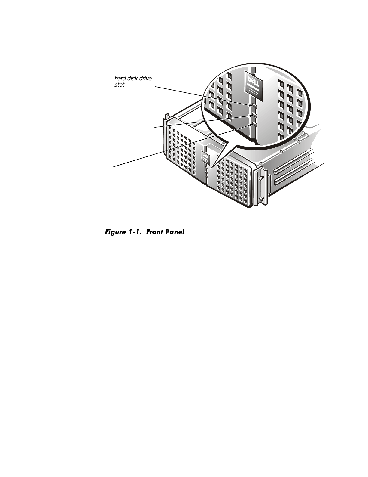
hard-disk drive
status indicator
fan/temperature
status indicator
power supply output
status indicator
)LJXUH )URQW 3DQHO
Introduction 1-5
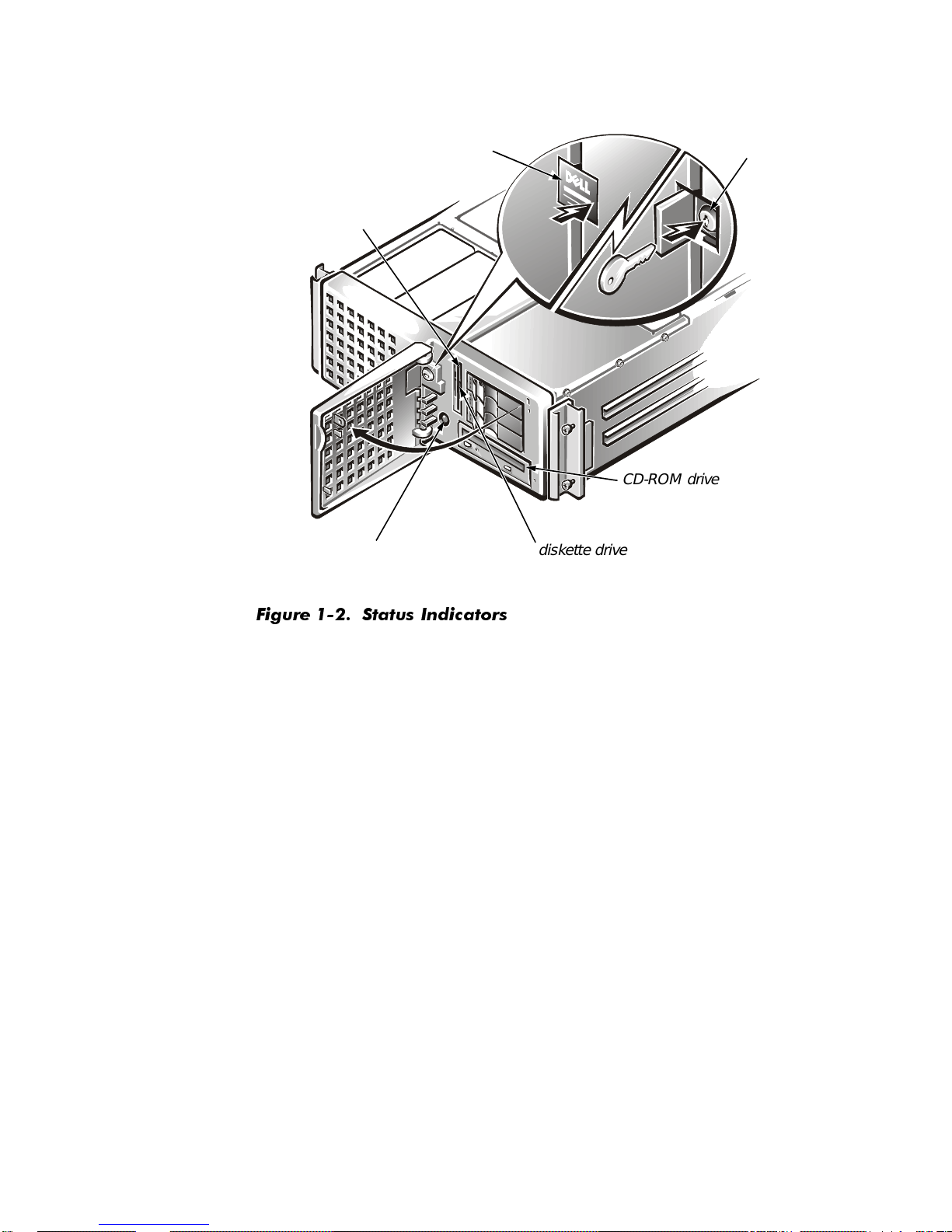
diskette drive
access indicator
lock access panel
bezel and
hard-disk
drive keylock
CD-ROM drive
power button
)LJXUH 6WDWXV ,QGLFDWRUV
diskette drive
1-6 Dell PowerEdge 6350 Systems User ’s Guide
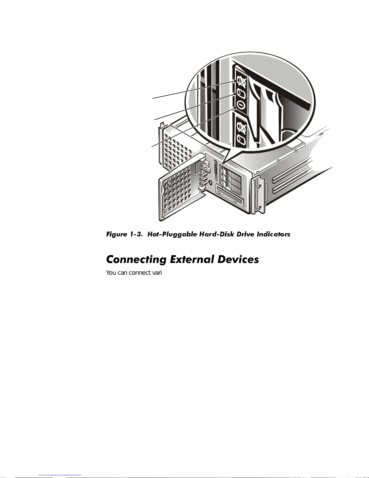
hard-disk drive
failure indicator
hard-disk drive
activity indicator
hard-disk drive
online indicator
)LJXUH +RW3OXJJDEOH +DUG'LVN 'ULYH ,QGLFDWRUV
&RQQHFWLQJ([WHUQDO'HYLFHV
You can connect various external devices, such as a mouse and printer, to the I/O
ports and connectors on the system’s back panel. The system BIOS detects the presence of external devices when you boot or reboot your system. When connecting
external devices to your system, follow these guidelines:
Check the documentation that accompanied the device for specific installation
and configuration instructions.
For example, most devices must be connected to a particular I/O port or connec-
tor to operate properly. Also, external devices like a mouse or printer usually
require you to load software files called
work. These sof tware drivers help the system recognize an external device and direct
its operation. Device drivers of this type are normally included with your operating system software.
Always attach extern al devices
before
external devices
specifies otherwise. (If the system does not seem to recognize the device, try turning
on the system before turning on the device.)
turning on the system unless the documentation for the device
while your system is turned off
device drivers
into memory before they will
. Then turn on an y
Introduction 1-7

For inf ormati on about enablin g, disabling, or configuri ng I/O ports and conn ectors, s ee
Chapter 4, “Using the System Setup Program,” or Chapter 5, “Using the Resource
Configuration Utility.” For detailed descriptions and illustrations of each port and connector on the I/O panel, see Appendix B, “I/O Ports and Connectors.”
3UHYHQWLQJ8QDXWKRUL]HG$FFHVV,QVLGHWKH
6\VWHP
A keylock behind the lock access panel on the front bezel prevents unauthorized
access to the hot-pluggable hard-disk drives, CD-ROM drive, diskette drive, and the
power switch, all of whi ch are behind the bezel. A second lock on top of the unit prevents the top cover from being opened and the fans from being removed.
The PowerEdge 6350 system also includes a system intrusion switch that signals
appropriate server management software if the top cover is opened.
*HWWLQJ+HOS
If at any time you don’t understand a procedure described in this guide, or if your system does not perform as expected, Dell provides a number of tools to help you. For
more informatio n on these help tools, see Chapter 12, “G e tting Help,” in your
tion and Troubleshooting Guide
.
Installa-
1-8 Dell PowerEdge 6350 Systems User ’s Guide

&+$37(5
8VLQJWKH'HOO6HUYHU$VVLVWDQW&'
This chapter describes the bootable
agement tasks you can perform with the CD to configure and maintain your system.
This chapter also describes the bootable utility partition installed on your system that
provides many of the same functions and utilities as the
Dell Server Assistant
CD and the system man-
Dell Server Assistant
CD.
%RRWLQJ)URPWKH&'
The system must be running to insert the
CD, insert it into the PowerEdge 6350 system’s CD-ROM drive and press
<Ctrl><Alt><Del>. When the system boots, the CD main menu appears.
If the CD does not boot, check the following settings:
In the System Setup program, the Secondary SCSI category must be set to On
and the Boot Sequence category must be set to Dis kette First (both of these
settings are the defaults for their respective categories). See Chapter 4, “Using
the System Setup Program,” for more information.
In the SCSI
must be set to Enabled.
ers,” for more information.
Select
utility, the BIOS Support For Bootable CD-ROM category
See Chapter 3, “Installing and Conf iguring SCSI Driv-
Dell Server Assistant
CD. To boot from the
1DYLJDWLQJWKH&'0HQXV
Selections can be made from the CD menus using either a keyboard or a mouse.
Associate d help inf ormation is displa y ed in the help bo x at the bottom of the screen in
the currently selected language (specified via a menu option).
Click Back to return to the previous menu. Click Exit (or press <Alt><x>) to exit the
program. Exiting the program causes the system to reboot to the standard
operating-system boot partition.
Using the Dell Server Assistant CD 2-1

8VLQJWKH&'
Dell Server Assistant
The
that you need to configure and maintain your system. The CD has an easy-to-use
graphical user interface that enables you to quickly navigate to any data on the CD
that you need. In addition, you are given a choice of several languages in which to
view and use the CD interface.
Dell Server As si stant
The
possible with clear, on-screen instructions and a number of automated configuration
utilities. In addition to the setup utilities, the CD allows you to create blank formatted
diskettes as well as diskettes of system utilities and operating system-specific drivers.
You can also use the CD to re-create the utility partition on the hard-disk drive of your
system if the existing utility partition ever becomes unusable or gets de leted from
your system.
You can access the online system docume nts, as well as other information, on any
desktop or server system that has a browser such as Microsoft Internet Explorer or
Netscape Navigator. When you put the CD in a system running the Microsoft
Windows
starts the browser software and displays the documentation welcome page. The
documents can ei ther be viewed online or printed on a printer for hardcopy viewing.
Also, if you have access to the Internet, the CD contains several useful and informative links to e xternal Internet W eb sites to pro vide y ou with u p-to-date inform ation and
downloadable system files.
®
95 operating system or Microsoft Windows NT, the system automatically
CD provides important system utilities and documentation
CD makes sy stem set up a nd configur ation as con v enient as
8WLOLW\3DUWLWLRQ
The utility partition is a bootable partition on the hard-disk drive that provides some of
the functions available on the
found on the CD are contained in the utility partition, occupying approximately
10 megabytes (MB) of space on the system’s hard-disk drive. When implemented,
the partition boots and provides an executable environment for the partition’ s utilities.
When the partition is not implemented, it is designated as a non–MS-DOS partition.
NOTE: The utility partition provides only limited MS-DOS functionality and cannot be
used as a general-purpose MS-DOS partition.
Dell has installed the utility partition on your hard-disk drive; however, reinstalling the
utility partition and/or its contents may be necessary if the version installed by Dell
becomes damaged or is removed from the hard-disk drive. You can reinstall the utility
partition and/or its contents using the
To start the utility partition, press the <F10> key during POST.
Like the
from which you invoke the partition’s utilities. Selections can be made using either a
keyboard or a mouse. Menu options and the associated help are displayed in the
currently selected language (specified via a menu option).
Dell Server As sistant
Dell Server Assistant
Dell Server Assistant
CD, the utility partition pro vid es a menu-dri ven interfa ce
CD. Most of the applications
CD.
2-2 Dell PowerEdge 6350 Systems User ’s Guide
As you move your cursor over an option in a menu, information about that option is
displayed at the bottom of the screen.
Click Back to return to the previous menu. Click Exit (or press <Alt><x>) to exit the
utility partition. Exiting the utility causes the system to reboot to the standard
operating-system boot partition.
Table 2-1 provides a sample list and explanation of the options on the utility partition
menu even when the
Dell Server Assistant
CD is not in the CD-RO M drive. The
options displayed on your system may vary depending on the configuration.
NOTE: Although most options are available from both the
Dell Server Assistant
CD
and the utility partition, some options, such as accessing online document ation, are
available only from the CD. The
Run Syste m Diagnostics
option is only av ailabl e from
the utility partition.
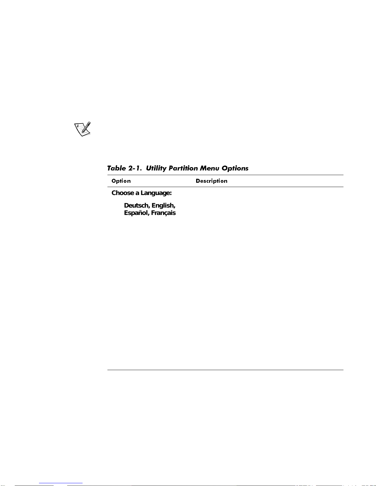
7DEOH 8WLOLW\ 3DUWLWLRQ 0HQX 2SWLRQV
2SWLRQ 'HVFULSWLRQ
Choose a Language:
Deutsch, English,
Español, Franç ais
Configure the System:
Run Resource Configuration Utility
Configure RAID
Subsystem
Run System Utilities:
Run System
Diagnostics
Allows the user to select the language in which to
display menus and messages.
Runs the RCU.
Runs the Dell PowerEdge Expa ndabl e RAID Control ler configuration utility if the con troller card is
present on your system.
Runs the system hardware diagnostics.
Upgrade Utility
Partition
Create Diskettes:
Create Blank Formatted Diskette
NOTE: For the full name of an abbreviation or acronym used in this table, see the Glossary.
Allows the user to upgrade the utility partition (for
example, adding, removing, or changing features
installed on the partition).
Creates a blank, formatted diskette.
Using the Dell Server Assistant CD 2-3
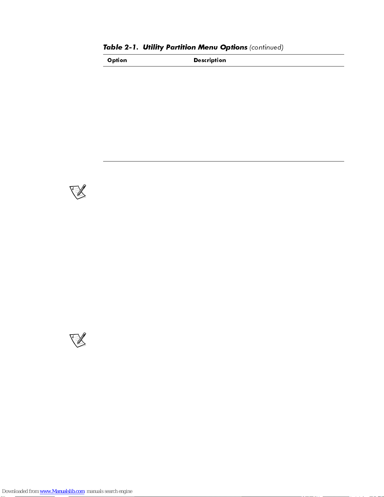
7DEOH 8WLOLW\ 3DUWLWLRQ 0HQX 2SWLRQV
2SWLRQ 'HVFULSWLRQ
Create Utility Diskettes:
FRQWLQXHG
Create RAID Configuration Utility Disk ette
Create Diagnostics
Diskette
Create System utility
Diskette
NOTE: For the full name of an abbreviation or acronym used in this table, see the Glossary.
Creates a bootable diskette for running the Dell
PowerEdge Expandable RAID Controller configuration utility (if the controller card is present on your
system). The RAID configuration utility provides an
alternative method for configuring the card.
Creates a bootable diskette from which the hardware diagnostics can be run.
Creates a bootable diskette from which utilities,
such as the Asset Tag utility, can be run.
NOTE: The options displayed on your system are dependent on your system configuration and may not include all of those listed here.
5XQQLQJ6\VWHP'LDJQRVWLFV
The sys tem diag nostics can be r un from the uti lity partition or from a disk ette, but not
from the
tem Utilities and then sel ec t Run Sys t e m Diagnos tics . To run the diagnostics from
a diskette, select Create Diagnostics Diskette from the Utility Partition menu.
Before running the diagnostics, you should make a blank diskette and insert it in the
diskette drive so the diagnostics programs can record critical messages and information as necessary. Use the Create Blank Formatted Diskette option to create a
formatted diskette. The system hardware diagnostics are described in Chapter 5,
“Running the Dell Diagnostics,” of the
Dell Server Assistant
CD. From the Utility Partition menu, select Run Sys-
Installation and Troubleshooting Guide
.
9LGHR'ULYHUV
NOTES: The ATI video for the Microsoft Windows NT Server 4.0 operating system
must be set up with a resolution of 640 x 480 at installation.
Windows NT Server 4.0 Service Pack 3 must be installed to use the updated drivers
for ATI video.
You need to install the video drivers for the operating system you install on your
Po werEdge 6350 system , un les s th ey were installed by Dell. Us e the following procedure to install the video drivers for Windows NT Server 4.0. The Novell NetWare
operating system provides a textual interface and does not require video drivers.
2-4 Dell PowerEdge 6350 Systems User ’s Guide

,QVWDOOLQJ9LGHR'ULYHUVIRU:LQGRZV 17
NOTE: Video drivers must be reinstalled after every installation of Windows NT 4.0
Service Pack 3.
Select the Cr eat e Di sk e t t es category from the Dell Server Assistant main menu, and
create a diskette of software drivers for Windows NT 4.0 to keep as a backup. After
you make the diskette of the drivers, use the following procedure to install the video
drivers:
1. Start Windows NT.
2. Log in as the administrator or as a user with administrative privileges.
For information on system administration, see the reference documentation for
Windows NT.
3. Click the Start button, point to Settings, and click Control Panel.
4. Double-click the Display icon.
The Display Sett ings window appears.
5. Select the Settings tab.
6. Click Display Type, and then click Change in the Adapter box.
A list of available video drivers is displayed.
7. C l i ck Have Disk.
8. Insert the
From Disk window.
9. Make sure that ATI Technologies Inc. 3D Rage Pro (the default) is selected in
the video driver list, and click Install.
The Installing Drivers dialog box appears.
10. Click Yes to proceed.
After the files are copied from the diskette, Windows NT prompts you to restart
your system. Click OK and close all open windows.
11. Remove the
Windows NT.
When you restart Windows NT, you can change the display resolution and color
depth.
12. Open the Program Manager, access the Control Panel, and select the Display
icon.
The Display Settings window appears.
ATI Installation Disk
ATI Installation Disk
into the diskette drive; then click OK in the Install
from the diskette drive, and restart
13. Select the desired resolu tion, number of colors, and refresh rate.
Using the Dell Server Assistant CD 2-5

$VVHW7DJ8WLOLW\
The Asset Tag utility allows you to enter an asset tag number for your system. The
default System Setup screen (see Figure 4-1) does not show the asset tag number
unless you enter one us ing this utility.
NOTE: The Asset Tag utility works only on systems running MS-DOS.
8VLQJWKH$VVHW7DJ8WLOLW\
Use the following procedure to create a system utility diskette and boot the system:
1. If you hav e not already don e so, create a bootable system utility disket te from the
CD using the Create Resour ce Con figuration Utility Disket te option discussed
earlier in this chapter.
2. Insert the diskette into drive A, and reboot the system.
NOTE: The system utility diskette contains CD-ROM drivers that provide access
to the CD-ROM drive when you boot from the diskette.
After y ou boot th e sy ste m with the system utility disket te, yo u can use the A sset
Tag utility to enter an asset tag num ber that y ou o r yo ur organiza tion assig n to the
system. You can also use the A s set Tag utility to reenter th e sy ste m’s service tag
number if that becomes necessary.
You can view the asset tag number using the System Setup program as
described in Chapter 4, “Using the System Setup Program.”
$VVLJQLQJ DQG 'HOHWLQJ DQ $VVHW 7DJ 1XPEHU
An asset tag number can have up to ten characters ; any combination of characters,
exclud ing spac es, is v alid . To assign o r c hang e an asset ta g number, type asset and a
space followed by the new number; then press <Enter>. For example, type the following command line and press <Enter>:
asset 1234567890
When prompted to verify the asset tag number, type y and press <Enter>. The system then displays the new or modified asset tag number and the service tag number.
To delete the asset tag number without assigning a new one, type asset /d and
press <Enter>.
Table 2-2 lists the command-line op tions y ou can use wi th the Asset Tag utility. To use
one of these options, type asset and a space followed by the option.
2-6 Dell PowerEdge 6350 Systems User ’s Guide
 Loading...