

Dell 4200, 4300, 4400, 6300, PowerEdge 5160 Installation Manual
...
Dell™ PowerEdge™ 4x00 and 6300 Systems
Tower Installation Guide
Systèmes Dell™ PowerEdge™ 4x00 et 6300
Guide d’installation en tour
Dell™ PowerEdge™ 4x00 und 6300 Systeme
Tower-Installationshandbuch
Sistemas Dell™ PowerEdge™ 4x00 y 6300
Guía de instalación en torre
™
www.dell.com

™
Dell™ PowerEdge™ 4x00 and 6300
Systems
TOWER
INSTALLATION GUIDE
www.dell.com
Notes, Notices, Cautions, and Warnings
Throughout this guide, blocks of text may be accompanied by an icon and printed in
bold type or in italic type. These blocks are notes, notices, cautions, and warnings,
and they are used as follows:
NOTE: A NOTE indicates important information that helps you make better use of
your computer system.
NOTICE: A NOTICE indicates either potential damage to hardware or loss
of data and tells you how to avoid the problem.
CAUTION: A CAUTION indicates a potentially hazardous situation which, if
not avoided, may result in minor or moderate injury.
WARNING: A WARNING indicates a potentially hazardous situation which,
if not avoided, could result in death or serious bodily injury.
____________________
Information in this document is subject to change without notice.
© 1999 Dell Computer Corporation. All rights reserved.
Trademarks used in this text: Dell,theDELL logo, and PowerEdge are trademarks of Dell
Computer Corporation. Other trademarks and trade names may be used in this document to
refer to either the entities claiming the marks and names or their products. Dell Computer
Corporation disclaims any proprietary interest in trademarks and trade names other than its own.
October 1999 P/N 26JVW Rev. A00

Contents
BeforeYouBegin ..................................................1-2
ImportantSafetyInformation ......................................... 1-2
KitRestrictions.................................................1-2
Rack Stabilizer Feet .............................................1-2
Recommended Tools ...............................................1-3
Installation........................................................1-3
ShuttingDownandTurningOfftheSystem ..........................1-3
RemovingtheDoorsFroma24-Uor42-URack .......................1-4
RemovingtheCableManagementArm..............................1-6
RemovingtheCableTray.........................................1-7
RemovingtheSystemFromtheRack...............................1-8
RemovingtheSystem........................................1-8
RemovingtheRailsandRackAdapters ..........................1-9
RemovingtheSlideAssembliesFromtheRack...................1-10
ReplacingtheRackDoors .......................................1-12
Installing the Rubber Feet .......................................1-13
RemovingtheFrontBezel.......................................1-14
ReorientingDrives.............................................1-15
ReorientingtheSystemBadge ...................................1-16
ReplacingtheFrontBezel .......................................1-16
AttachingCablesandTurningtheSystemOn........................1-17
Index
Figures Figure1-1. TowerKitContents ......................................1-2
Figure 1-2. Opening the Latch on the Door .............................1-4
Figure1-3. Removingthe42-URackDoors.............................1-5
Figure1-4. Removingthe24-URackDoors.............................1-6
Figure 1-5. Disconnecting the Cable Management Arm ................... 1-7
iii

Figure1-6. RemovingtheCableTray ................................. 1-8
Figure1-7. RemovingtheSystemFromtheRack........................ 1-9
Figure1-8. RemovingtheRailsandRackAdapters...................... 1-10
Figure1-9. RemovingtheSlideAssemblies........................... 1-11
Figure1-10. RemovingaCageNut................................... 1-12
Figure 1-11. Installing the Rubber Feet ................................1-13
Figure1-12. RemovingtheSystemCover.............................. 1-14
Figure1-13. RemovingtheFrontBezel................................ 1-15
iv

Dell™ PowerEdge™ 4x00 and
6300 Systems Tower
Installation Guide
This installation guide provides instructions for trained service technicians converting
one or more Dell PowerEdge 4x00 or 6300 rack-mounted computer systems into a
tower configuration.
WARNING: The power supplies in this computer system produce high
voltages and energy hazards, which can cause bodily harm. Only
trained service technicians are authorized to perform this procedure,
which includes removing the system cover and accessing the components
inside the system.
One tower kit is required for each system you are converting to the tower
configuration. The tower kit includes the following items (see Figure 1-1):
•
Four rubber feet
•
18 plastic filler plugs
•
Four 8-32 x 0.5-inch hex-head, thread-forming screws
NOTE: The nonmetric screws called out in illustrations and referenced in procedural
steps are identified first by size and then by the number of threads per inch. For
example, a #8 Phillips-head screw with 32 threads per inch is identified as an
8-32 screw.
supp ort.dell.com Dell PowerEdge 4x00 and 6300 Systems Tower Installation Guide 1-1
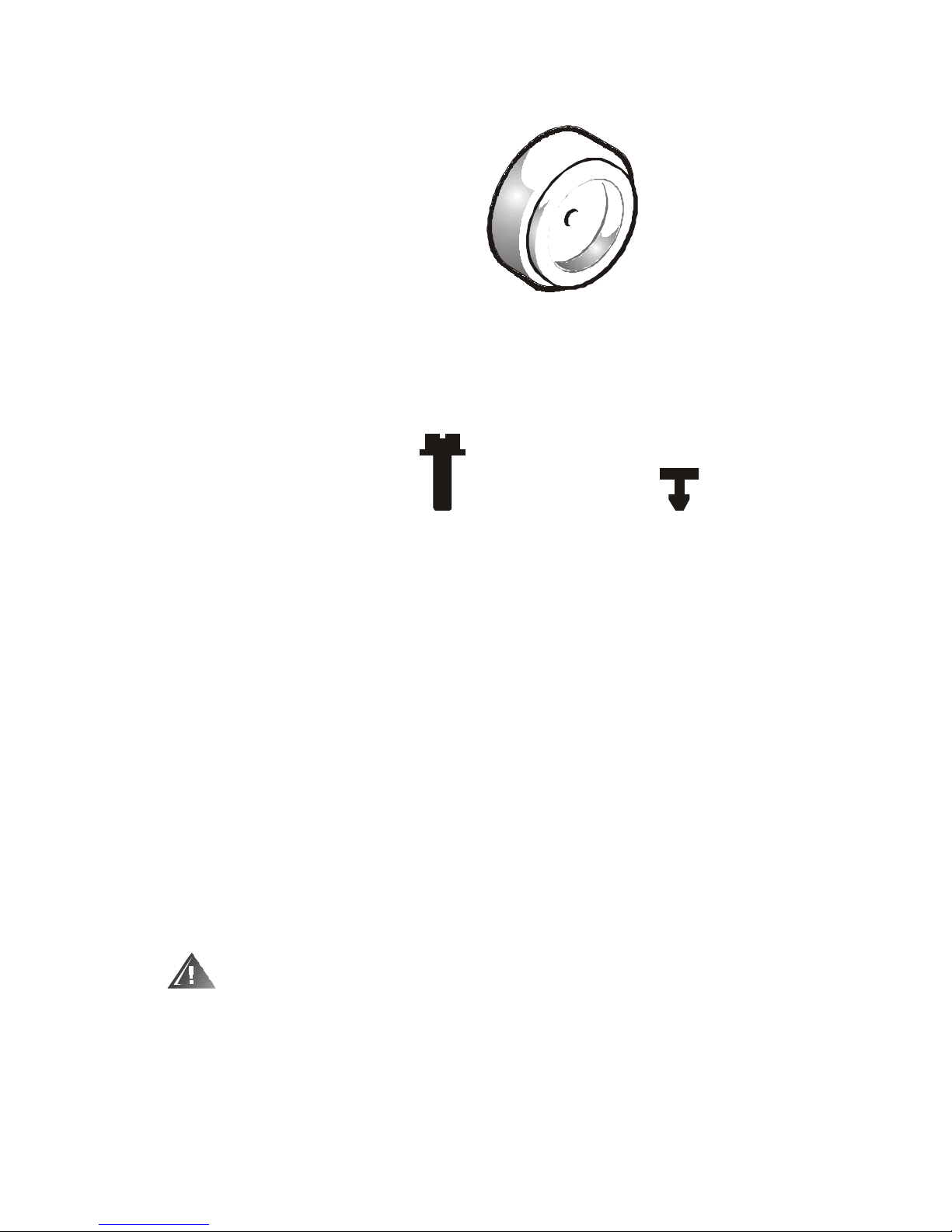
rubber feet (4)
8-32 x 0.5-inch hex-head,
thread-forming screws (4)
plastic filler plugs (18)
Figure 1-1. Tower Kit Contents
Before You Begin
Before you begin removing your system from the rack, carefully read the safety
precautions and tool requirements in the following sections.
Important Safety Information
Follow these safety precautions when removing your system from the rack.
Kit Restrictions
This tower kit is intended to be installed by trained service technicians.
Rack Stabilizer Feet
WARNING: Removing PowerEdge systems from a Dell rack without the
front and side stabilizer feet installed could cause the rack to tip over,
pot entially resulting in bodily injury under certain circumstances.
Therefore, always install the stabilizer feet before removing components
from the rack.
1-2 Dell PowerEdge 4x00 and 6300 Systems Tower Installation Guide

WARNING: Never pull more than one system out of the rack on its slide
assemblies at one time. The weight of more than one extended system
could cause the rack to tip over and injure someone.
The stabilizer feet help prevent the possibility of the rack tipping over when a
system or other components are pulled out of the rack far enough so that the slide
assemblies are fully extended. Refer to the Dell PowerEdge Rack-Mountable
Solutions Installation Guide provided with the rack for instructions on installing the
stabilizer feet.
Recommended Tools
To install the tower kit, you need the following tools:
•
A #2 Phillips screwdriver
•
A flat-blade screwdriver
Installation
To install a tower kit, perform these steps (see the following subsections for detailed
instructions):
1. Shut down and turn off the system.
2. Remove the rack’s front and rear doors.
3. Remove the cable management arm.
4. Remove the cable tray.
5. Remove the system from the rack.
6. Replace the rack doors.
7. Install the rubber feet.
8. Remove the front bezel.
9. Reorient the drives.
10. Reorient the system badge.
11. Replace the front bezel.
12. Attach the cables and turn the system on.
Shutting Down and Turning Off the System
It is usually best to perform this installation at a time when there are no users on the
system. Shut down all application programs running on the server and turn off the
system.
supp ort.dell.com Dell PowerEdge 4x00 and 6300 Systems Tower Installation Guide 1-3
 Loading...