

®
Dell® PowerEdge® 6300 Systems
SERVICE MANUAL
www.dell.com

____________________
Information in this document is subject to change without notice.
© 1998 Dell Computer Corporation. All rights reserved.
Reproduction in any manner whatsoever without the written permission of Dell Computer Corporation is strictly forbidden.
Trademarks used in this text: Dell, the DELL logo, and PowerEdge are registered trademarks and Dell OpenManage is a trademark of Dell Computer
Corporation; Microsoft, Windows, Windows NT, and MS-DOS are registered trademarks of Microsoft Corporation; IBM is a registered trademark of
International Business Machines Corporation; Intel and Pentium are registered trademarks and MMX and Xeon are trademarks of Intel Corporation.
Other trademarks and trade names may be used in this document to refer to either the entities claiming the marks and names or their products. Dell
Computer Corporation disclaims any proprietary interest in trademarks and trade names other than its own.
June 1998 P/N 33697

CHAPTER 1
System Overview
®
Dell
PowerEdge
systems that use Intel
technology and incorporate a high-performance PCI local bus.
The PowerEdge 6300 systems have been designed for better serviceability
and increased reliability. The sliding system board tray allows easy access to
the system board for performing processor and memory upgrades. The Delldesigned SCSI backplane board and hard-disk drive carriers eliminate the
extensive cabling and drive configuration usually required for a SCSI subsystem. The plastic drive rails attached to devices mounted in the external
drive bays allow you to remove these devices without removing a single
screw. The systems can be used either freestanding or rack-mounted.
A PowerEdge 6300 system can contain up to four Pentium II Xeon microprocessors. Each processor is housed in a single-edge contact (SEC) cartridge/
heat sink assembly mounted in a guide bracket on the system board, allowing
for greater heat dissipation. The processor has an internal operating frequency
of 400 MHz (or a higher speed when available) and an external operating frequency of 100 MHz. Contact Dell for information about Dell-supported
microprocessor upgrades.
®
6300 systems are feature-rich, enterprise-class server
®
Pentium® II Xeon™ microprocessor(s) with MMX™
System Features
In addition to the standard features found in a traditional personal computer,
Dell PowerEdge 6300 systems include the following new and/or advanced
features:
• One to four Intel Pentium II Xeon microprocessors with an internal operat-
ing frequency of 400 MHz (and higher speeds when available) and an
external bus speed of 100 MHz.
• Support for symmetric multiprocessing (SMP) when two or more micro-
processors are installed.
NOTE: Additional microprocessors must have the same internal operating
frequency as the initial microprocessors. Not all versions of the Pentium II
microprocessor will work properly as additional microprocessors in this
system; the upgrade kit from Dell contains the correct version for this
system.
• A secondary (L2) cache of 512 KB, 1 MB, or 2 MB of SRAM is included
within the SEC cartridge that contains the microprocessor.
System Overview 1-1

• A minimum of 128 MB of system memory, upgradable to a maximum of
4 GB by installing combinations of 32-, 128-, and 256-MB buffered EDO
DIMMs in the 16 DIMM sockets on the memory board.
• BIOS in upgradable flash memory on the PCI bus.
• Up to six hot-pluggable SCSI hard-disk drives. Two additional 1-inch drives
can be installed in the optional removable media bay.
• Three redundant, hot-pluggable power supplies and a power-supply paral-
leling board (PSPB).
• Five redundant system cooling fans.
• Seven PCI connectors, four 64-bit and three 32-bit.
• Three peer-to-peer PCI expansion subsystems.
• A VGA-compatible video subsystem with an ATI 3D RAGE PRO SVGA video
controller. This video subsystem contains 2 MB of SGRAM video memory
(nonupgradeable).
• A National Semiconductor PC87309 super I/O controller that controls the
bidirectional parallel port, two serial ports, and the diskette drive in the
externally accessible front bay.
• Two Adaptec AIC-7890 Ultra2/LVD SCSI host adapters that support up to
six 1.6-inch internal SCSI hard-disk drives via a SCSI backplane board and
special SCSI hard-disk drive carriers.
NOTE: The 1.6-inch drive carriers will accommodate 1-inch drives.
The SCSI backplane automatically configures SCSI ID numbers and SCSI
termination on individual hard-disk drives, greatly simplifying drive installation. The backplane supports hot-pluggable SCSI hard-disk drive installation
and removal when used in conjunction with the PowerEdge Expandable
RAID controller.
• An Adaptec AIC-7860 Ultra/Narrow SCSI-III host adapter that supports up
to three externally accessible SCSI devices in the external hard-disk drive
bays.
• Drive failure, online, and activity indicators visible on each hard-disk drive
connected to the SCSI backplane.
• Server management circuitry that monitors operation of the system fans
as well as critical system voltages and temperatures. The server management circuitry works in conjunction with the HP OpenView Network Node
Manager Special Edition (NNM SE) and the Dell OpenManage™ Hardware
Instrumentation Package (HIP) software package.
• System board support for the Dell OpenManage Remote Assistant when
the optional Dell Remote Assistant Card (DRAC) is installed, which provides additional local and remote server management.
For a complete list of system features, see “Technical Specifications” found later in
this chapter. For information about installing the PowerEdge 6300 systems in a
rack, see the Dell PowerEdge 6300 Systems Rack Kit Installation Guide.
1-2 Dell PowerEdge 6300 Systems Service Manual

When following the text in this manual, assume that the location or direction
back of computer
right side
left side
front of computer
power switch
power indicator
drive access indicators (3)
power-supply status indicator
hard-disk
drive keylock
diskette drive
CD-ROM drive
fan/temperature status indicator
relative to the computer is as shown in Figure 1-1. Figures 1-2 through 1-4
illustrate front-panel, back-panel, and interior features of the PowerEdge 6300
systems.
Figure 1-1. Computer Orientation
Figure 1-2. Front-Panel Features
System Overview 1-3
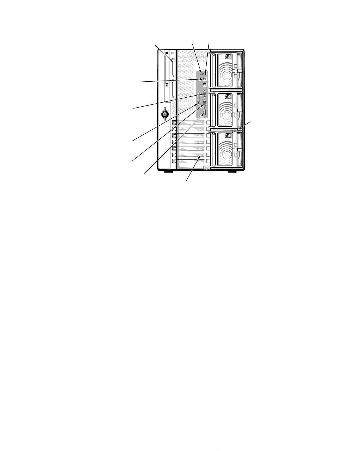
Figure 1-3. Back-Panel Features
parallel port
connector
serial port 2
connector
mouse
connector
keyboard
connector
serial port 1
connector
video connector
server
management
bus (SMB)
connectors (2)
SCSI connector port
expansion slots (7)
AC power receptacles (3)
1-4 Dell PowerEdge 6300 Systems Service Manual

hard-disk
drive bays (6)
external drive
bays (4)
SCSI backplane
board
system board
tray
latch
PCI expansion
card
support
panel
memory
module
microprocessors
hard-disk drive
cooling fan
assembly
system-board fans
Figure 1-4. Back/Right Side Internal View
System Overview 1-5
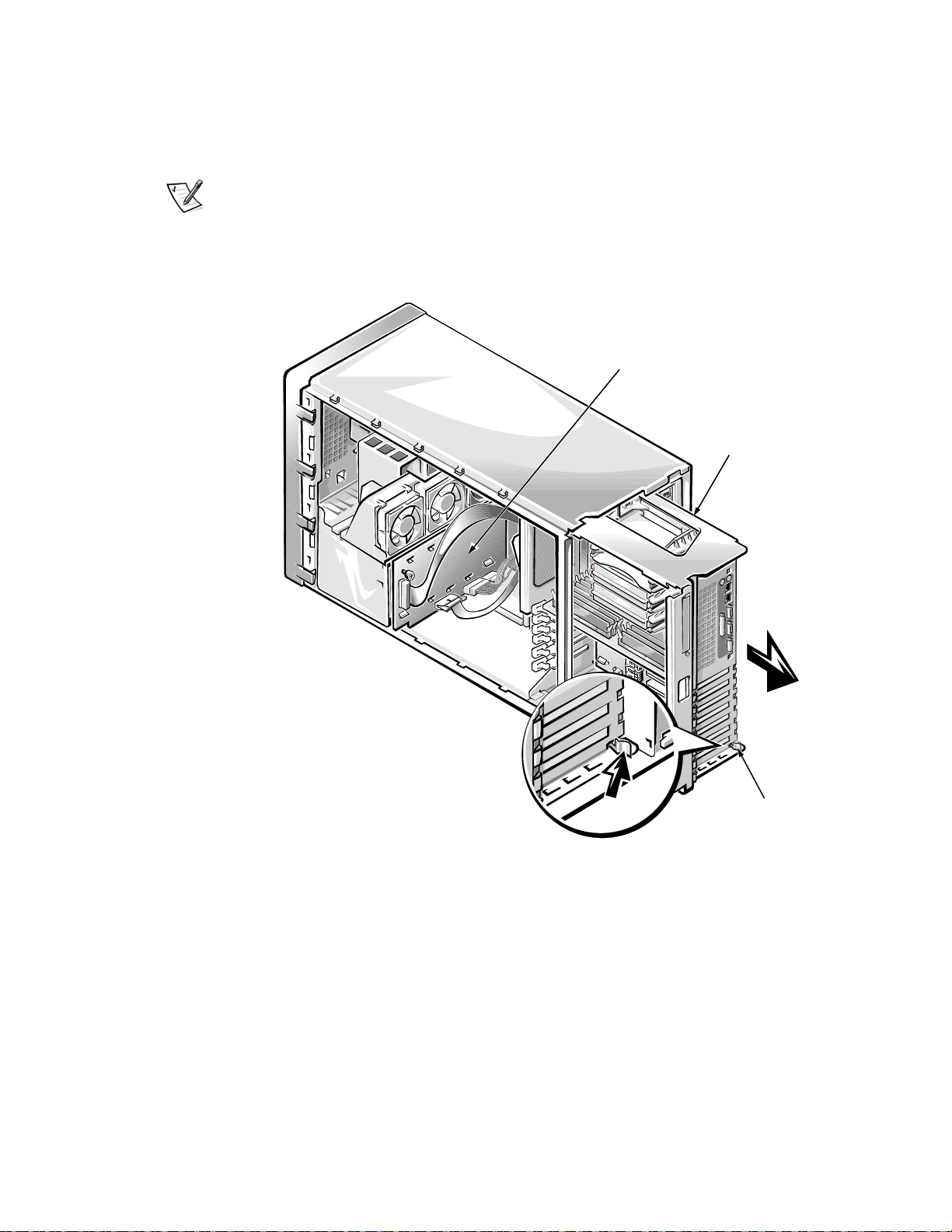
Accessing the Interior of the System
system
board tray
SCSI backplane
board
tray
latch
To access the SCSI backplane board or the PSPB, release the system-board
tray latch at the back lower corner of the tray (see Figure 1-5) and pull the tray
open to the first stop position, or service position).
NOTE: From the service position, if you depress and release the tray latch and
pull the tray out again, you will come to a second stop position that is used by
manufacturing. To remove the tray completely from any position, depress the
latch, hold it in, and pull the tray out of the chassis.
Figure 1-5. Opening the System Board Tray
1-6 Dell PowerEdge 6300 Systems Service Manual
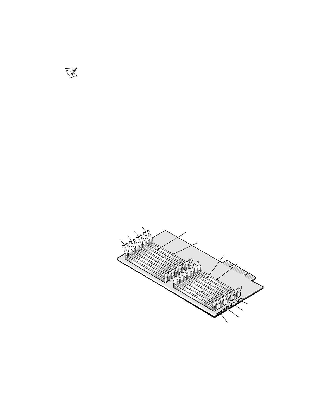
System Memory
bank 1
bank 4
DIMM D socket
bank 3
bank 2
bank 1
bank 4
bank 3
bank 2
DIMM C socket
DIMM B socket
DIMM A socket
System memory resides on a memory module card and consists of a minimum of 128 MB of 72-bit buffered EDO memory. Memory can be expanded
up to 4 GB by installing combinations of 32-, 128-, and 256-MB buffered EDO
DIMMs on the memory module.
NOTE: DIMMs must be rated at 50 or 60 ns. With a mixture of 50- and 60-ns
DIMMs, system memory will run at 60 ns.
The memory module provides 16 168-pin DIMM sockets divided into four
banks, each consisting of four sockets labeled “DIMM A” through “DIMM D”
(see Figure 1-6). Memory upgrade guidelines are as follows:
• DIMMs must be installed one bank (four DIMMs) at a time, starting with
bank 1 and working toward bank 4. There should be no open banks
between populated banks.
• Within a bank, install DIMMs in the following order: DIMM A, DIMM B,
DIMM C, and DIMM D.
• DIMM sizes cannot be mixed within a memory bank. However, one mem-
ory bank can hold different-size DIMMs from another memory bank.
• Of the DIMMs to be installed in the system, install the size you have the
most of in the lowest-numbered bank(s), the less numerous size in the
next banks, and least numerous size in the highest-numbered banks being
used. For example, when installing four 256-MB DIMMs, eight 128-MB
DIMMs, and four 32-MB DIMMs, install the 128-MB DIMMs in banks 1
and 2. The 256- and 32-MB DIMMs can be installed in banks 3 and 4; it
does not matter which bank holds which size.
Figure 1-6. Memory Module
For more detailed information about DIMM installation guidelines and samples
of DIMM configurations, see “Adding Memory” in Chapter 8 of the Dell
PowerEdge 6300 Systems Installation and Troubleshooting Guide.
System Overview 1-7

See “DIMMs” in Chapter 4 of this document for information on removing and
replacing DIMMs.
PCI Expansion Subsystem
The Resource Configuration Utility (RCU) included with the system automatically configures installed PCI expansion cards. For more information on the
RCU, see Chapter 5, “Using the Resource Configuration Utility,” in the Dell
PowerEdge 6300 Systems User’s Guide.
The seven expansion-card slots include four 64-bit and three 32-bit PCI expansion-card connectors located on the system board (see Figure 1-13). The 64-bit
slots support both 32- and 64-bit cards.
Video Controller
The video subsystem is built into the system board and consists of a PCI VGAcompatible video subsystem with an ATI 3D RAGE PRO SVGA video controller.
The video subsystem contains 2 MB of SGRAM video memory, which is not
upgradable. Maximum noninterlaced resolutions are 640 x 480 (16.7 million
colors), 800 x 600 (16.7 million colors), and 1024 x 768 (256 colors).
Integrated SCSI Controllers
Two integrated Adaptec AIC-7890 Ultra2/LVD SCSI host adapters support up to
six 1- or 1.6-inch internal SCSI hard-disk drives through a 68-pin connector on
the system board for a SCSI backplane board. The SCSI backplane board automatically configures SCSI ID numbers and SCSI termination on individual harddisk drives, greatly simplifying drive installation. The integrated SCSI controller
resides on the PCI local bus for optimum performance.
An integrated Adaptec AIC-7860 Ultra/Narrow SCSI host adapter attached to
the PCI bus supports up to three SCSI devices in the external drive bays
through a 50-pin connector on the system board.
SCSI Hard-Disk Drives
Dell PowerEdge 6300 systems include a SCSI backplane board, which greatly
simplifies cabling and configuration for SCSI hard-disk drives. SCSI ID and termination for SCSI hard-disk drives are both configured by the SCSI backplane
board, rather than on individual drives. SCSI hard-disk drives are supplied by
Dell in special drive carriers that fit in the internal drive bays.
NOTE: For maximum performance, install Ultra2/LVD drives exclusively.
Although you can install a mixture of Ultra2/LVD and Ultra hard-disk drives,
they will operate at the slower Ultra transfer rate.
1-8 Dell PowerEdge 6300 Systems Service Manual

SCSI Configuration Guidelines
SCSI hard-disk drives must be configured as follows:
• Disable termination on the drive. The SCSI backplane board provides termi-
nation for the SCSI bus.
• Set the SCSI ID on all drives to 0. All SCSI ID numbers for the drives are set
by the SCSI backplane board.
• Configure the drive so that the drive motor waits for a start unit command
from the SCSI host adapter before spinning.
SCSI devices in the external drive bays are controlled by the Ultra/Narrow SCSI
controller on the system board. Although SCSI devices are installed essentially
the same way as other devices, their configuration requirements are different.
To configure SCSI devices installed in the external bays, follow the guidelines
in the following subsections.
SCSI ID Numbers
Each device attached to the Ultra/Narrow SCSI host adapter must have a
unique SCSI ID number from 0 to 7.
When SCSI devices are shipped from Dell, the default SCSI ID numbers are
assigned as follows:
• The onboard Ultra/Narrow SCSI host adapter is configured through the
BIOS as SCSI ID 7.
• A SCSI tape drive is configured as SCSI ID 6 (the default ID number for a
tape drive).
• A SCSI CD-ROM drive is usually configured as SCSI ID 5.
NOTE: There is no requirement that SCSI ID numbers be assigned sequentially or
that devices be attached to the cable in order by ID number.
Device Termination
All Dell PowerEdge 6300 systems have an active terminator installed at the
end of the SCSI cable. All of the devices attached to the SCSI cable should
have their termination disabled.
PSPB and System Power Supplies
The Dell PowerEdge 6300 includes a PSPB and three 320-W redundant system power supplies.
System Power Supplies
The system power supplies are stacked at the rear of the chassis and can slide
in and out of the unit. When fully installed, a power supply automatically mates
with a power harness attached to the back plate of the power supply cage. The
power harness connects the power supply to the PSPB.
System Overview 1-9

The power supplies can operate from an AC power source of 115 VAC at 60 Hz
or 230 VAC at 50 Hz. They provide the DC operating voltages and currents
listed in Table 1-1.
NOTE: The power supplies produce DC voltages only under their loaded condition. Therefore, when you measure these voltages, the DC power connectors
must be mated to their PSPB harnesses at the bulkhead, and the harnesses
must be connected to their corresponding power input connectors on the
PSPB. The PSPB in turn must be connected as appropriate to the system
board, SCSI backplane board, or external drive bay.
.
Table 1-1. DC Voltage and Current Ranges
Voltage Range
Maximum Output Current
1
+3.3 VDC +3.23 to +3.45 VDC 18.0 A
+5 VDC +4.90 to +5.25 VDC 40.0 A
+12 VDC +11.40 to +12.60 VDC 16.0 A
–12 VDC –10.80 to –13.20 VDC
0.5
2
A
–5 VDC –4.50 to –5.50 VDC 0.3 A
+5 VFP
1
Maximum continuous combined load on +5 VDC and +3.3 VDC outputs cannot exceed
240 W.
2
Maximum combined load current on –5 VDC and –12 VDC outputs cannot exceed 0.6 A.
+4.85 to +5.35 VDC 0.4 A
PSPB
The PSPB multiplexes input from the power supplies to supply redundant
power to the system board, SCSI backplane, and external drive bays. Through
embedded server management (ESM), the PSPB can also be used to perform
such tasks as detecting the presence of one to three power supplies; monitoring voltage and current outputs from the power supplies, voltage going to the
system board, and fan RPMs; and supporting the SMB_ALERT protocol used
by the server management bus.
The PSPB connects to the power supplies through short harnesses that attach
to the back of the power supply cages. The PSPB is attached to the side wall of
the computer behind the external drive cage and is oriented in parallel with the
system board. For information on removing and replacing the PSPB, see
“Power-Supply Paralleling Board” in Chapter 4.
Figure 1-7 shows the PSPB power connector layout; Table 1-2 shows the cable
connections made from the PSPB.
1-10 Dell PowerEdge 6300 Systems Service Manual

Figure 1-7. Power-Supply Paralleling Board
system-board power
cable connector
(PWR2)
system-board power
cable connector
(PWR1)
system-board power
cable connector
(PWR3)
SCSI backplane-board
power cable connector
(HD_B/P)
external-drives power
cable connector (FD)
cable connectors –
power supply #1
PS1_PB1 (top) and
PS1_PB2
cable connectors –
power supply #2
PS2_PB1 (top) and
PS2_PB2
cable connectors –
power supply #3
PS3_PB1 (top) and
PS3_PB2
.
Table 1-2. Power Cable Connections From the PSPB
Connector Cable Connection
PS1_PB1 and
To the power connector on the first power supply
PS1_PB2
PS2_PB1 and
PS2_PB2
PS3_PB1 and
PS3_PB2
To the power connector on the second power
supply
To the power connector on the third power
supply
PWR1 To POWER1 connector on system board
PWR2 To POWER2 connector on system board
PWR3 To POWER3 connector on system board
FD To diskette drives and other devices in external
drive bays
HD_B/P To POWER connector on SCSI backplane board
System Overview 1-11
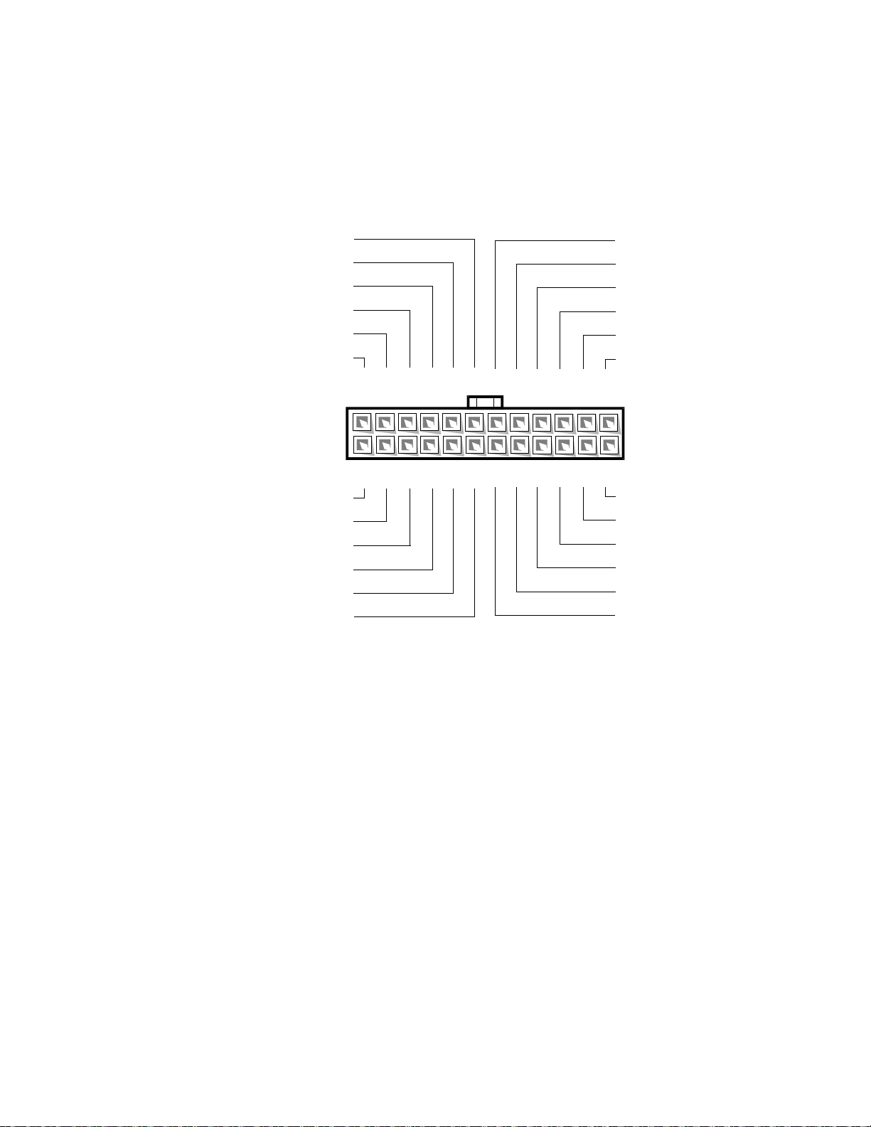
Pin Assignments for the PSPB Power Connectors
13 14 15 16 17
common (black)
+5 VL (red)
NC_TFSC (gray)
+5 VL (red)
SYS_PS_ON #
1
(gray)
common (black)
common (black)
common (black)
–5 VL (white)
+3.3 VL (orange)
18
+5 VL (red)
19 20 21 22 23 24
+5 VL (red)
12345
+12 VL (yellow)
+3.3 V_SENSE (orange)
common (black)
common (black)
+5 VFP (violet)
SYS_POWER_GOOD
2
(gray)
SENSE (black)
+5 V_SENSE (red)
common (black)
–12 VL (blue)
6
+5 VL (red)
789101112
+3.3 VL (orange)
The power-supply output voltages can be measured at the back (wire side) of
the connectors without disconnecting them. In the following diagrams, voltages for the PSPB PWRx connectors are shown as measured at the system
board; voltages for the PSPB FD connector are shown as measured at the
PSPB; voltages for the PSPB HD_B/P connector are shown as measured at the
SCSI backplane.
1-12 Dell PowerEdge 6300 Systems Service Manual
1
Pin 13 — SYS_PS_ON# should measure between +4.75 and +5 .25 VDC except when the
power button on the front panel is pressed, taking SYS_PS_ON# to its active-low state.
2
Pin 5 — SYS_PWR_GOOD should measure between +4.75 and +5.25 VDC when the power
supply is operating to indicate that all power-supply output voltages are within the ranges
specified in Table 1-1.
Figure 1-8. PSPB DC Power Connector PWR1
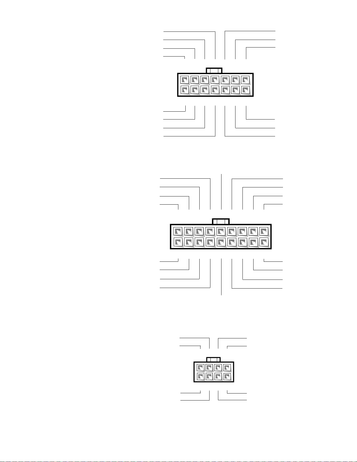
Figure 1-9. PSPB Power Connector PWR2
1
PLANAR_ID (gray)
I2C_SCL_EXT (gray)
I2C_SDA_EXT (gray)
23 45 6 7
+5 VL (red)
common (black)
+3.3 VL (orange)
12C_ALRT_EXT# (gray)
8
common (black)
+5 VL (red)
PRES_DET (gray)
91011121314
+12 VL (yellow)
common (black)
+5 VL (red)
common (black)
1
234
5
67
8
9
10
11
12
13
14
15
16 17 18
common (black)
+5 VL (red)
+12 VL (yellow)
+3.3 VL (orange)
+3.3 VL (orange)
+3.3 VL (orange)
+12 VL (yellow)
+5 VL (red)
common (black)
common (black)
common (black)
common (black)
common (black)
common (black)
common (black)
common (black)
common (black)
common (black)
1
common (black)
+12 VL (yellow)
common (black)
+5 VL (red)
+12 VL (yellow)
common (black)
+5 VL (red)
common (black)
56
4
3
2
87
Figure 1-10. PSPB Power Connector PWR3
Figure 1-11. PSPB Power Connector FD
System Overview 1-13
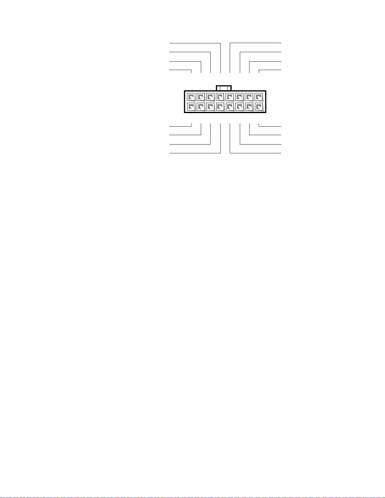
Figure 1-12. PSPB Power Connector HD_B/P
1
common (black)
P2
+12 VL (yellow)
common (black)
+12 VL (yellow)
2345678
+3.3 VL (orange)
common (black)
+12 VL (yellow)
common (black)
9
NC_I2C_ALRT# (gray)
+5 VL (red)
common (black)
+5 VL (red)
10 11 12 13 14 15 16
NC_I2C_SCL_EXT (gray)
NC_I2C_SDA_EXT (gray)
common (black)
+5 VL (red)
1-14 Dell PowerEdge 6300 Systems Service Manual
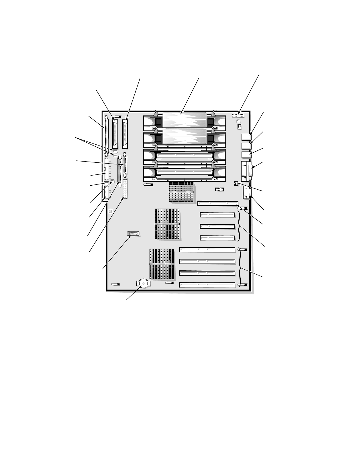
System Board Layout
video connector (VGA)
parallel port connector
(PARALLEL [top]) and
serial port connectors (2)
(SERIAL1 and SERIAL2
[bottom])
keyboard and
mouse connectors
(KYBD/MOUSE)
diskette-drive
interface
connector (FLOPPY)
battery connector (BATTERY)
Ultra/Narrow SCSI
connector
(SECONDARY SCSI)
speed and
configuration jumpers
front of system board
microprocessors (4)
(PROC_1 [top] through
PROC_4)
32-bit PCI connectors
(PCI1 [top] through PCI3)
power input
connector (POWER1)
Ultra2/LVD SCSI
connector (PRIMARY
SCSI-B)
SCSI backplane board
interface cable connector
(BACKPLANE)
server management bus
connector (XSMB_IN)
fan connector (FAN3)
server management bus
connector (XSMB_OUT)
Dell Remote Assistant
Card connector (SVR_MGT)
PCI activity indicator
connector (PCILEDPNL)
Ultra2/LVD SCSI
connector (PRIMARY
SCSI-A)
power input
connector (POWER2)
power input
connector (POWER3)
64-bit PCI connectors
(PCI4 through PCI7)
memory board
connector
(MEMORY_BD)
fan connectors
(FAN1, FAN2)
chassis intrusion
switch
connector (INTRUS2)
The subsections that follow provide service-related information about the system board components. Figure 1-13 illustrates the location of important
system board components.
Figure 1-13. System Board Components
System Overview 1-15

SCSI Backplane Board Layouts
Ultra2/LVD
SCSI cable
connector (SCSI)
power input
connector (POWER)
system-board data
cable connector (PLANAR)
SCA-2–compatible SCSI
connectors on reverse side
(SLOT0 through SLOT5)
cooling fan
power cable
connector (FAN)
Figure 1-14 shows the location of the connectors on the SCSI backplane board.
Figure 1-14. SCSI Backplane Board
CAUTION: Should you remove power from the SCSI backplane board
(either by removing the power cable or during replacement of the
system board battery), you may need to reflash your system’s
firmware.
The original firmware on the SCSI backplane is stored in EEPROM.
However, if the SCSI backplane firmware is ever updated, the update
is stored in volatile RAM. If power is removed from an updated backplane board, the update will be lost and the board will revert to its
original firmware in EEPROM.
If at system startup you receive the message Warning: Firmware is
out-of-date, please update..., it is best to reflash all system
firmware from your Dell Server Assistant CD.
1-16 Dell PowerEdge 6300 Systems Service Manual

System Board Jumpers
jumpered
unjumpered
Figure 1-15 illustrates the location of the system board jumpers, and Table 1-3
describes the jumper settings.
Figure 1-15. System Board Jumpers
System Overview 1-17

Table 1-3. Jumper Descriptions
Jumper Settings
PASSWD Installed (default) to enable the password feature. Remove
the jumper and boot the computer to remove an existing
password.
CARDBIOS Not installed (default) to allow normal boot operation from
the system BIOS.
Install the jumper only to boot the system from a BIOS
expansion card.
ISA_CLR Not installed (default) to retain the ISA configuration set-
tings at system boot. Install the jumper and boot the computer to clear the ISA configuration settings. Remove the
jumper before restoring ISA configuration information.
RSVD1 Do not install. Reserved for future microprocessor speed.
RSVD2 Do not install. Reserved for future microprocessor speed.
350MHZ Do not install.
400MHZ Installed only if the microprocessor’s internal speed is
400 MHz.
450MHZ Installed only if the microprocessor’s internal speed is
450 MHz (when available).
500MHZ Installed only if the microprocessor’s internal speed is
500 MHz (when available).
Interrupt Assignments
Table 1-4 lists the default IRQ line assignments.
Table 1-4. Interrupt Assignments
IRQ Line Used/Available
IRQ0 Used by the system timer
IRQ1 Used by the keyboard to signal that the output buffer is full
IRQ2 Used by interrupt controller 1 to enable IRQ8 through IRQ15
IRQ3 Used by serial port 2 (COM2 and COM4)
IRQ4 Used by serial port 1 (COM1 and COM3)
IRQ5 Available unless used by a secondary parallel port
IRQ6 Used by the diskette drive controller
IRQ7 Used by the primary parallel port
IRQ8 Used by the RTC
IRQ9 Used for power management functions
1-18 Dell PowerEdge 6300 Systems Service Manual

Table 1-4. Interrupt Assignments (continued)
IRQ Line Used/Available
IRQ10 Available
IRQ11 Available
IRQ12 Used by the PS/2 mouse port unless mouse is disabled in
System Setup program
IRQ13 Used by the math coprocessor
IRQ14 Available
IRQ15 Used by embedded server-management functions
DMA Channel Assignments
Table 1-5 lists the default DMA channel assignments.
Table 1-5. DREQ Line Assignments
DREQ Line Used By/Available
DREQ0 Not required for PCI-only system
DREQ1 Not required for PCI-only system
DREQ2 Generated by super I/O controller to initiate DMA cycle for
attached diskette drive
DREQ3 Not required for PCI-only system
DREQ4 Generated by bus controller chip to activate second DMA
controller
DREQ5 Not required for PCI-only system
DREQ6 Not required for PCI-only system
DREQ7 Not required for PCI-only system
System Overview 1-19

Technical Specifications
Table 1-6 lists detailed technical specifications.
Table 1-6. Technical Specifications
Microprocessor
Microprocessor type . . . . . . 1 to 4 Intel Pentium II Xeon microprocessors
Microprocessor speed. . . . . 400 MHz (100 MHz externally);
higher internal speeds when available, all
with 100-MHz external speeds
Internal cache . . . . . . . . . . . 512-KB, 1-MB, or 2-MB L2 cache
Math coprocessor . . . . . . . . internal to the microprocessor
System Information
System chipset . . . . . . . . . . Intel 450NX controller chipset
Data bus width . . . . . . . . . . 64 bits
Address bus width. . . . . . . . 32 bits
Expansion Bus
Bus types. . . . . . . . . . . . . . . 32- and 64-bit PCI local bus
Bus speed . . . . . . . . . . . . . . 33.33 MHz
PCI expansion-card
connectors. . . . . . . . . . . . . . three 32-bit and four 64-bit full-length slots
System Clocks
System clock . . . . . . . . . . . . 100 MHz
Diskette/
communications ports . . . . . 48 MHz from the system clock
SCSI channels . . . . . . . . . . . three 40-MHz channels
Memory
Architecture . . . . . . . . . . . . . 4-way interleaved 50- or 60-ns buffered EDO
DIMMs
DIMM sockets . . . . . . . . . . . (16) 168-pin sockets
DIMM capacities . . . . . . . . . 32-, 128-, and 256-MB buffered EDO
Standard RAM . . . . . . . . . . . 128 MB (minimum)
Maximum RAM . . . . . . . . . . 4 GB
BIOS address. . . . . . . . . . . . F000:0000h–F000:FFFFh
External cache . . . . . . . . . . . none
1-20 Dell PowerEdge 6300 Systems Service Manual

Table 1-6. Technical Specifications (continued)
Integrated SCSI Controllers
Types . . . . . . . . . . . . . . . . . . two Adaptec AIC-7890 Ultra2/LVD (Fast-40)
controllers, with integrated 68-pin SCSI
connectors on the system board;
Adaptec AIC-7860 Ultra/Narrow controller,
with integrated 50-pin SCSI connector on the
system board
Drives
Externally accessible
bays . . . . . . . . . . . . . . . . . . . one 3.5-inch bay dedicated to a diskette drive;
one 5.25-inch bay (upper bay) containing a
CD-ROM drive; two 5.25-inch bays for optional devices. Optional cage can be installed
in the two option bays to support two additional hard-disk drives.
Internally accessible
bays . . . . . . . . . . . . . . . . . . . six bays for SCSI hard-disk drives
Ports
Externally accessible:
Serial (DTE) . . . . . . . . . . two 9-pin connectors; 16550-compatible
Parallel . . . . . . . . . . . . . . one 25-hole connector (bidirectional)
Video . . . . . . . . . . . . . . . one 15-hole connector (VGA-compatible)
PS/2-style keyboard . . . . 6-pin mini-DIN
PS/2-compatible
mouse . . . . . . . . . . . . . . 6-pin mini-DIN
Server-management bus
daisy-chain connector. . . two modular 8-pin connectors
Internally accessible:
Ultra2/LVD SCSI
controllers . . . . . . . . . . . two 68-pin connectors
Ultra/Narrow SCSI
controller . . . . . . . . . . . . 50-pin connector
Diskette drive . . . . . . . . . 34-pin connector
System Overview 1-21

Table 1-6. Technical Specifications (continued)
Controls and Indicators
Power control. . . . . . . . . . . . push button behind drive door on front panel
Power indicator . . . . . . . . . . green LED behind drive door on front panel
Fan/temperature status
indicator . . . . . . . . . . . . . . . . green LED on front panel (blinks amber for
fan failure or out-of-bounds temperature)
Power-supply status
indicator . . . . . . . . . . . . . . . . green LED on front panel (blinks amber for
power supply or system voltage fault)
Drive online indicator . . . . . . green LED on each SCSI drive carrier
Drive activity indicator . . . . . green LED on each SCSI drive carrier
Drive failure indicator . . . . . . amber LED on each SCSI drive carrier (blinks
if drive failure is detected)
Video
Video type . . . . . . . . . . . . . . ATI 3D RAGE PRO video controller; VGA
connector
Video memory
(standard). . . . . . . . . . . . . . . 2 MB (not upgradable)
Power
DC power supply:
Wattage . . . . . . . . . . . . . 320 W per supply
Voltage . . . . . . . . . . . . . . 115 V at 60 Hz;
230 V at 50 Hz
Backup battery . . . . . . . . . . . 3.0-V CR2032 lithium coin cell
Physical
Height (with support
feet) . . . . . . . . . . . . . . . . . . . 44.5 cm (17.5 inches)
Width . . . . . . . . . . . . . . . . . . 30.5 cm (12.0 inches)
Depth. . . . . . . . . . . . . . . . . . 71.1 cm (28.0 inches)
Weight (maximum
configuration). . . . . . . . . . . . 50.0 kg (110.0 lb)
1-22 Dell PowerEdge 6300 Systems Service Manual

Table 1-6. Technical Specifications (continued)
Environmental
Temperature:
Operating . . . . . . . . . . . . 10° to 35°C (50° to 95°F)
Storage . . . . . . . . . . . . . –40° to 65°C (–40° to 149°F)
Relative
humidity . . . . . . . . . . . . . 8% to 80% (noncondensing)
Maximum vibration:
Operating . . . . . . . . . . . . 0.25 G at 3 to 200 Hz for 15 min
Storage . . . . . . . . . . . . . –0.5 G at 3 to 200 Hz for 15 min
Maximum shock:
Operating . . . . . . . . . . . . six shock pulses in the positive and nega-
tive x, y, and z axes at 50 G for 2 ms
Storage . . . . . . . . . . . . . six shock pulses in the positive and nega-
tive x, y, and z axes at 92 G for 2 ms
Altitude:
Operating . . . . . . . . . . . . –16 to 3048 m (–50 to 10,000 ft)
Storage . . . . . . . . . . . . . –16 to 10,600 m (–50 to 35,000 ft)
System Overview 1-23
 Loading...