

Page 1

Dell™ PowerConnect™
M6348 Stackable Switches
Getting Started Guide
使用入门指南
入門指南
Guide de mise en route
Handbuch zum Einstieg
Panduan Pengaktifan
はじめに
시작 안내서
Guía de introducción
Model PCM6348
www.dell.com | support.dell.com
הדובע תליחת ךירדמ
Page 2

Page 3

Dell™ PowerConnect™
M6348 Stackable Switch
Getting Started Guide
Model PCM6348
www.dell.com | support.dell.com
Page 4

Notes, Notices, and Cautions
NOTE: A NOTE indicates important information that helps you make better use of your computer.
NOTICE: A NOTICE indicates either potential damage to hardware or loss of data and tells you how to avoid the problem.
CAUTION: A CAUTION indicates a potential for property damage, personal injury, or death.
____________________
Information in this document is subject to change without notice.
© 2009 Dell Inc. All rights reserved.
Reproduction in any manner whatsoever without the written permission of Dell Inc. is strictly forbidden.
Trademarks used in this text: Dell, the DELL logo, and PowerConnect are trademarks of Dell Inc.; Microsoft and Windows are registered
trademarks of Microsoft Corporation.
Other trademarks and trade names may be used in this document to refer to either the entities claiming the marks and names or their products.
Dell Inc. disclaims any proprietary interest in trademarks and trade names other than its own.
Model PCM6348
November 2009 P/N H851N Rev. A01
Page 5

Contents
Installation
Site Preparation . . . . . . . . . . . . . . . . . . . . . . . . . . . . . . 5
Unpacking the Switch
Package Contents
Unpacking Steps
Connecting a Switch to a Terminal
Assembling a Stack
. . . . . . . . . . . . . . . . . . . . . . . . . . . 5
. . . . . . . . . . . . . . . . . . . . . . . . . . . 5
. . . . . . . . . . . . . . . . . . . . . . . . . . . 5
. . . . . . . . . . . . . . . . . . . . . 6
. . . . . . . . . . . . . . . . . . . . . . . . . . . . 6
Starting and Configuring the Switch
Connecting the Terminal to the Switch . . . . . . . . . . . . . . . . . . . 8
Booting the Switch
Initial Configuration
Initial Configuration Procedure
Example Session
. . . . . . . . . . . . . . . . . . . . . . . . . . . . 9
. . . . . . . . . . . . . . . . . . . . . . . . . . . . 9
. . . . . . . . . . . . . . . . . . . . . 10
. . . . . . . . . . . . . . . . . . . . . . . . . . . 10
Managing a Stack
Master and Member Switches . . . . . . . . . . . . . . . . . . . . . . . 13
Stack Startup
Topology Discovery
Auto Stack ID Assignment
Firmware Version Checking
System Initialization
. . . . . . . . . . . . . . . . . . . . . . . . . . . . . . . 13
. . . . . . . . . . . . . . . . . . . . . . . . . . 13
. . . . . . . . . . . . . . . . . . . . . . . 14
. . . . . . . . . . . . . . . . . . . . . . 14
. . . . . . . . . . . . . . . . . . . . . . . . . . 14
CLI/ Telnet/ Web Interface
. . . . . . . . . . . . . . . . . . . . . . . . . 15
Insertion and Removal of Switches
Operating as Standalone Switch
Stack ID Renumbering
User Controls
. . . . . . . . . . . . . . . . . . . . . . . . . . . . . . . 15
. . . . . . . . . . . . . . . . . . . . . . . . . 15
. . . . . . . . . . . . . . . . . . . 15
. . . . . . . . . . . . . . . . . . . . 15
3
Page 6

Advanced Configuration . . . . . . . . . . . . . . . . . . . . . . . . . . 16
Retrieving an IP Address From a DHCP Server
Security Management and Password Configuration
. . . . . . . . . . . . . 16
. . . . . . . . . . . 17
Managing the Switch
Using a Web Browser to Manage the Switch . . . . . . . . . . . . . . . . 20
Starting the Application
Understanding the Interface
. . . . . . . . . . . . . . . . . . . . . . . . 20
. . . . . . . . . . . . . . . . . . . . . . 20
4
Page 7

Installation
This document provides basic information to install, configure, and operate
Dell™ PowerConnect™ M6348 systems. For more information, see the
which is available on your
support.dell.com
for the latest updates on documentation and firmware.
User Documentation
CD, or check the Dell Support web site at
Site Preparation
Before installing the switch, make sure that the chosen installation location meets the site
requirements specified in the
Hardware Owner’s Manual
.
Unpacking the Switch
Package Contents
When unpacking each switch, make sure that the following items are included:
• One PowerConnect switch
• One USB type A-to-DB9 serial cable
User Documentation
•
• Getting Started Guide
• Product Information Guide
CD
Hardware Owner’s Manual
,
Unpacking Steps
NOTE: Before unpacking the switch, inspect the container and immediately report any evidence of
damage.
Place the container on a clean, flat surface and cut all straps securing the container.
1
2
Open the container or remove the container top.
3
Carefully remove the switch from the container and place it on a secure and clean surface.
4
Remove all packing material.
5
Inspect the product and accessories for damage.
Getting Started Guide 5
Page 8
Connecting a Switch to a Terminal
1
Connect the DB9 connector of the USB-to-DB9 serial cable to a VT100 terminal or to a
computer running VT100 terminal emulation software.
2
Connect the USB connector at the other end to the USB port on the switch.
NOTE: If you are installing a stack of switches, connect the terminal to the Master Switch. When a stack
is powered up for the first time, the switches elect the Master Switch, which may occupy any location in
the stack. If you connect the terminal to a member (non-Master) switch, you will not be able to use the
command line interface (CLI).
Assembling a Stack
www.dell.com | support.dell.com
The software supports up to 12 stacked switches, supporting up to 576 1G ports. Each
PowerConnect M6348 switch provides two stacking ports at the bottom of the switch.
CAUTION: Ensure that a switch is turned off before adding it to the stack.
Use the 1-meter stacking cables to connect the stacking ports in the following manner:
1
Insert a stacking cable in the bottom stacking port on the first switch.
2
Connect the cable to the upper stacking port on the next switch.
3
Continue connecting each switch to the next until all switches are connected in a ring.
4
On the last switch in the stack, connect the cable to the upper stacking port on the first
switch to create a loop.
If necessary, use a separately purchased 3-meter stacking cable to connect the last switch to
the first.
Figure 1 shows a chassis with six connected M6348 switches.
6 Getting Started Guide
Page 9
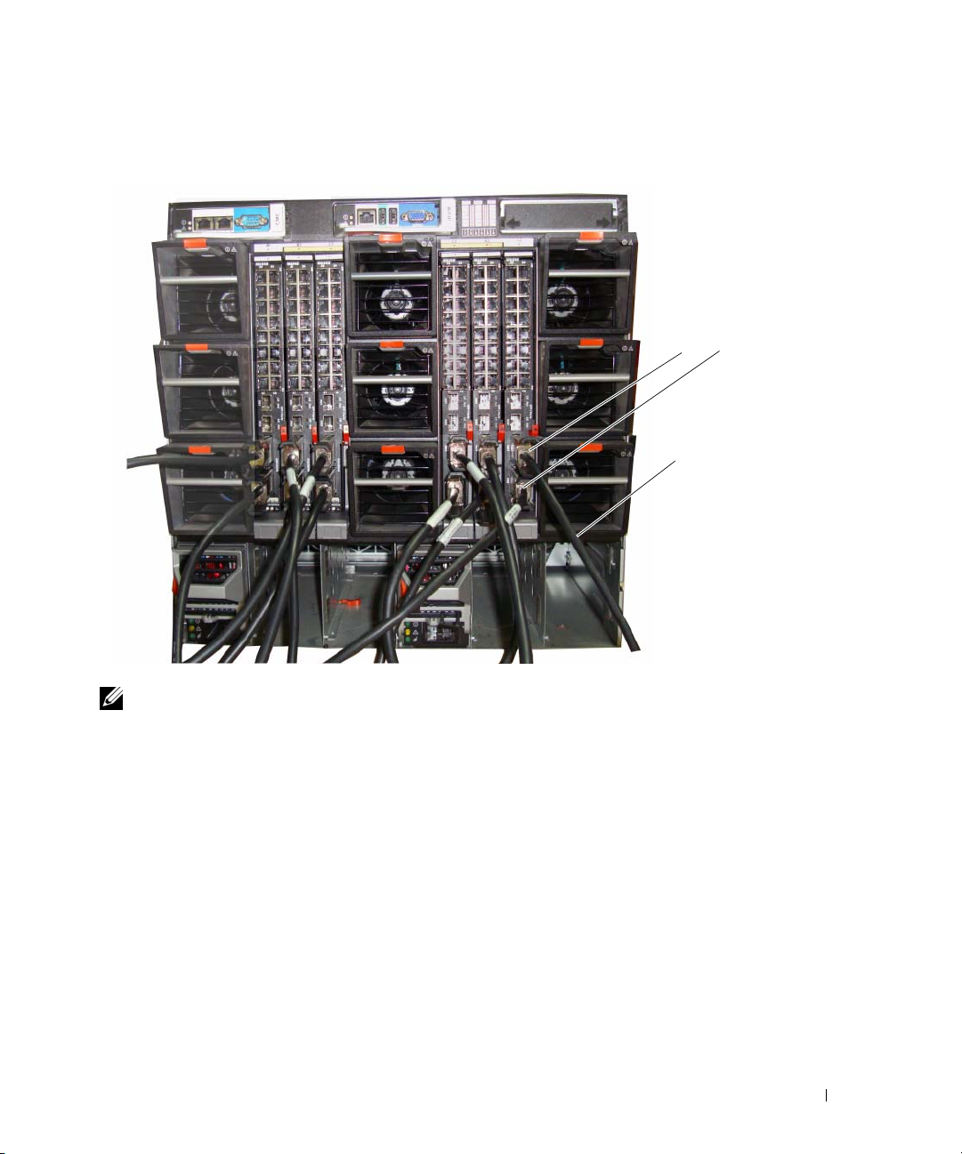
Figure 1. Connecting a Stack of Switches
upper and lower
stacking ports
stacking cable
NOTE: The resulting ring topology allows the entire stack to function as a single switch with resilient
fail-over capabilities.
Getting Started Guide 7
Page 10

Starting and Configuring the Switch
After completing all external connections, connect a terminal to a switch to configure the switch
or stack. Additional advanced functions are described in the
User Documentation
NOTE: Read the release notes for this product before proceeding. You can download the release notes
from the Dell Support website at support.dell.com.
NOTE: We recommend that you obtain the most recent version of the user documentation from the Dell
Support website at support.dell.com.
CD.
User's Guide
located on your
www.dell.com | support.dell.com
Connecting the Terminal to the Switch
To monitor and configure the switch via serial console, use the console port on the rear of the
switch to connect it to a VT100 terminal or to a computer running VT100 terminal emulation
software. The console port is implemented as a data terminal equipment (DTE) connector.
The following is required to use the console port:
• VT100-compatible terminal or a desktop or a portable system with a serial port, running
VT100 terminal emulation software.
• A serial cable (provided) with a USB type A connector for the console port and DB9
connector for the terminal.
Perform the following tasks to connect a terminal to the switch console port:
NOTE: If you are installing a stack of switches, you need to assemble and cable the stack before
powering up and configuring it.
Connect the DB9 connector on the serial cable to the terminal running VT100 terminal emulation
1
software.
2
Configure the terminal emulation software as follows:
a
Select the appropriate serial port (serial port 1 or serial port 2) to connect to the console.
b
Set the data rate to 9600 baud.
c
Set the data format to 8 data bits, 1 stop bit, and no parity.
d
Set the flow control to none.
e
Set the terminal emulation mode to
f
Select Terminal keys for Function, Arrow, and Ctrl keys. Make sure that the setting is for
Terminal keys (not Microsoft
VT100
®
Windows® keys).
.
NOTE: When using HyperTerminal with Microsoft Windows 2000, make sure that you have Windows
2000 Service Pack 2 or later installed. With Windows 2000 Service Pack 2, the arrow keys function
properly in HyperTerminal's VT100 emulation. Go to www.microsoft.com for more information on
Windows 2000 service packs.
8 Getting Started Guide
Page 11
3
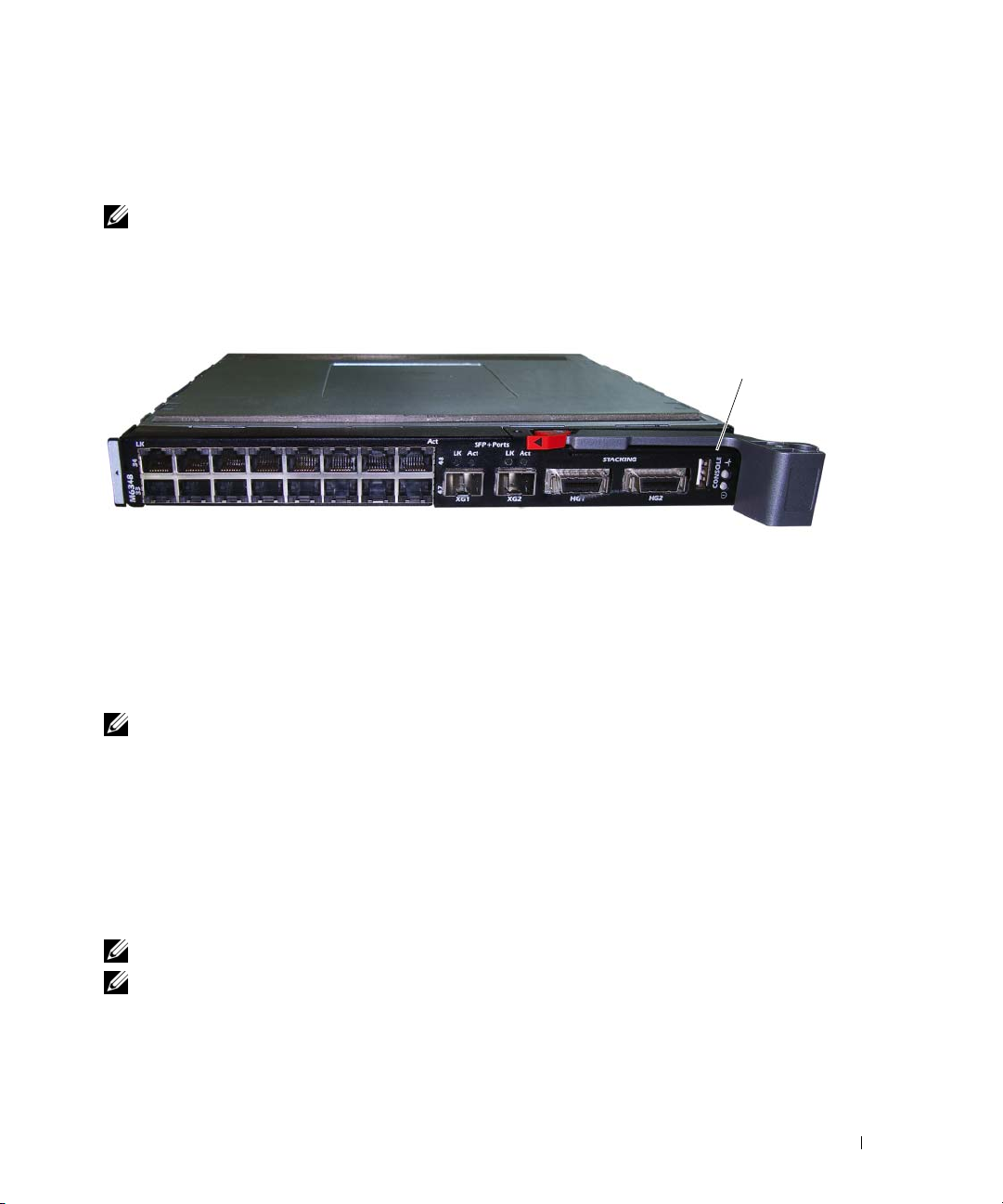
Connect the USB type A connector on the USB cable directly to the switch USB console port.
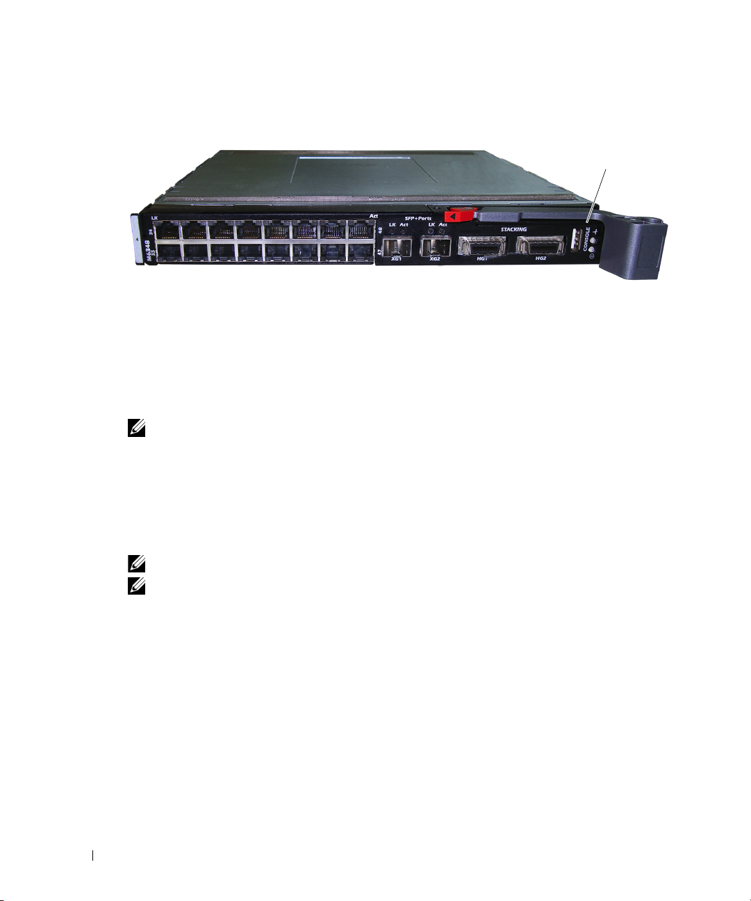
The PowerConnect M6348 USB console port is located on the left side of the rear panel, as
shown in Figure 2.
NOTE: If you are installing a stack of switches, connect the terminal to the Master Switch. When a stack
is powered up for the first time, the switches elect the Master Switch, which may occupy any location in
the stack. If you connect the terminal to a member switch, you will not be able to use the CLI.
Figure 2. Connecting to the Console Port
console port
Booting the Switch
Refer to the
Hardware Owner’s Manual
for instructions on booting the switch.
Initial Configuration
NOTE: The initial simple configuration procedure is based on the following assumptions:
• The PowerConnect switch was never configured before and is in the same state as when you
received it.
• The PowerConnect switch booted successfully.
• The console connection was established and the Dell Easy Setup Wizard prompt appears on the
screen of a VT100 terminal or terminal equivalent.
The initial switch configuration is performed through the console port. After the initial
configuration, you can manage the switch either from the already-connected console port or
remotely through an interface defined during the initial configuration.
NOTE: The switch is not configured with a default user name and password.
NOTE: All of the settings below are necessary to allow the remote management of the switch through
Telnet (Telnet client) or HTTP (Web browser).
Getting Started Guide 9
Page 12

Before setting up the initial configuration of the switch, obtain the following information from
your network administrator:
• The IP address to be assigned to the management VLAN.
• The IP subnet mask for the network.
• The IP address of the management VLAN default gateway.
Initial Configuration Procedure
You can perform the initial configuration using the Dell Easy Setup Wizard, or by using the
Command Line Interface (CLI). The Setup Wizard automatically starts when the switch
configuration file is empty. You can exit the wizard at any point by entering [ctrl+z], but all
www.dell.com | support.dell.com
configuration settings specified will be discarded (the switch will use the default values).
For more information on CLI initial configuration see the
shows how to use the Setup Wizard for initial switch configuration. The wizard sets up the following
configuration on the switch:
• Establishes the initial privileged user account with a valid password. The wizard configures
one privileged user account during the setup.
• Enables CLI login and HTTP access to use the local authentication setting only.
• Sets up the IP address for the management VLAN.
• Sets up the SNMP community string to be used by the SNMP manager at a given IP address.
You may choose to skip this step if SNMP management is not used for this switch.
• Allows you to specify the management server IP or permit management access from all IP
addresses.
• Configures the default gateway IP address.
User Guide
. This
Getting Started Guide
Example Session
This section describes an Easy Setup Wizard session. The following values are used by the example
session:
• The SNMP community string to be used is
• The network management system IP address is
• The user name is
• The IP address for the management VLAN is
• The default gateway is
10 Getting Started Guide
admin
, and password is
0.0.0.0
DellNetworkManager
192.168.2.1
admin123
192.168.2.1:255.255.255.0
.
.
.
.
.
Page 13

The setup wizard configures the initial values as defined above. After you complete the wizard,
the switch is configured as follows:
• SNMPv1/2c is enabled and the community string is set up as defined above. SNMPv3 is
disabled by default.
• The admin user account is set up as defined.
• A network management system is configured. From this management station, you can access
the SNMP, HTTP, and CLI interfaces. You may also choose to allow all IP addresses to access
these management interfaces by choosing the (0.0.0.0) IP address.
• An IP address is configured for the default management VLAN (1).
• A default gateway address is configured.
NOTE: In the example below, the possible user options are enclosed in [ ]. Also, where possible, the
default value is provided in { }. If you press <Enter> with no options defined, the default value is accepted.
Help text is in parentheses.
The following example contains the sequence of prompts and responses associated with running an
example Dell Easy Setup Wizard session, using the input values listed above.
After the switch completes the POST and is booted, the following dialog appears:
Unit 1 - Waiting to select management unit)>
Applying configuration, please wait ...
Welcome to Dell Easy Setup Wizard
The Setup Wizard guides you through the initial switch
configuration, and gets you up and running as quickly as possible.
You can skip the setup wizard, and enter CLI mode to manually
configure the switch. You must respond to the next question to run
the setup wizard within 60 seconds, otherwise the system will
continue with normal operation using the default system
configuration.Note: You can exit the setup wizard at any point by
entering [ctrl+z].
Would you like to run the setup wizard (you must answer this
question within 60 seconds)? [Y/N] y
Step 1:
The system is not setup for SNMP management by default. To manage
the switch using SNMP (required for Dell Network Manager) you can
. Set up the initial SNMP version 2 account now.
. Return later and setup other SNMP accounts. (For more
information on setting up an SNMP version 1 or 3 account, see
the user documentation).
Would you like to setup the SNMP management interface now? [Y/N] n
Getting Started Guide 11
Page 14

Step 2:
Now we need to setup your initial privilege (Level 15) user
account. This account is used to login to the CLI and Web
interface. You may setup other accounts and change privilege
levels later. For more information on setting up user accounts and
changing privilege levels, see the user documentation.
To setup a user account:
Please enter the user name. [root]:root
Please enter the user password:********
Please reenter the user password:********
www.dell.com | support.dell.com
Step 3:
Next, an IP address is setup. The IP address is defined on the
default VLAN (VLAN #1), of which all ports are members. This is the
IP address you use to access the CLI, Web interface, or SNMP
interface for the switch. Optionally you may request that the
system automatically retrieve an IP address from the network via
DHCP (this requires that you have a DHCP server running on the
network).
To setup an IP address:
Please enter the IP address of the device (A.B.C.D) or enter "DHCP"
(without the quotes) to automatically request an IP address from
the network DHCP server. [192.168.2.1]:192.168.2.1
Please enter the IP subnet mask (A.B.C.D or /nn).
[255.255.255.0]:255.255.255.0
Step 4:
Finally, setup the default gateway. Please enter the IP address of
the gateway from which this network is reachable. [0.0.0.0]:
This is the configuration information that has been collected:
User Account setup = root
Password = ********
Management IP address = 192.168.2.1 255.255.255.0
Default Gateway = 0.0.0.0
Step 5:
Do you want to select the operational mode as Simple Mode? [Y/N] n
12 Getting Started Guide
Page 15

Step 6:
If the information is correct, please select (Y) to save the
configuration, and copy to the start-up configuration file. If the
information is incorrect, select (N) to discard configuration and
restart the wizard: [Y/N] y
Thank you for using Dell Easy Set up Wizard. You will now enter CLI
mode.
Managing a Stack
Master and Member Switches
A stack of switches can be managed as a single entity when connected together. The stack can be
managed from a web-based interface, an SNMP management station, or a CLI. When a stack is
created, one switch automatically becomes the master switch. You can manually allocate an IP
address to the master switch using the console, or let DHCP do so automatically. Afterwards,
you can manage the entire stack through the IP address of the Master Switch. The Master Switch
detects and reconfigures the ports with minimal operational impact in the event of:
• Switch failure
• Inter-switch stacking link failure
• Switch insertion
• Switch removal
If the Master Switch goes off line, any of the Member Switches in the stack can replace it.
The system will elect a new Master Switch and reconfigure the System Configuration for the stack.
Stack Startup
Topology Discovery
When a stack is formed, a topology discovery process builds up a database that contains
information about all of the switches in the stack, including the Firmware Version, Hardware
Version, Management Preference, Switch MAC Address, and Switch Serial Number. You can use
the command line interface (CLI) or the Web interface to view this information.
NOTE: See the CLI Reference Manual and the User’s Guide for assistance with the CLI and Web
interface, respectively.
Getting Started Guide 13
Page 16

Auto Stack ID Assignment
During the stack formation process, every switch is assigned a Stack ID. Once Stack ID assignment
is complete, each switch saves its Stack ID into the nonvolatile FLASH memory. You can use the
CLI or the Web interface to view the stack IDs.
Firmware Version Checking
Following Stack ID assignment, the Master Switch performs a consistency check to make sure that
all switches in the stack are running the same firmware version.
If the switch software versions do not match, then the ports on the member switch will not become
valid for operation. This condition is known as the Suspended Stacking Mode. You can then
www.dell.com | support.dell.com
synchronize the firmware on the member switch with the firmware that is running on the Master
Switch.
System Initialization
If the Master Switch determines during the firmware version consistency check that all switches are
running the same version of firmware, the switch will be initialized for Stacking Mode.
System Initialization for Normal Stacking Mode
The Master Switch will initialize the stack using the last saved system configuration file. For those
switches that do not have a configuration file, the system will apply default settings to those
switches.
If the configuration file is corrupted, the Master Switch will initialize the stack and set it to the
Factory Default Configuration.
You can save the configuration file. The Master Switch automatically distributes the configuration
file to the member switches. If the Master Switch later becomes unavailable, a Member Switch
becomes the new Master Switch and configures the stack with the latest configuration
synchronized from the Master Switch.
System Initialization for Suspended Stacking Mode
After system initialization is complete, the Master Switch will enter Suspended Stacking Mode if
the firmware versions of the stack are inconsistent. In this mode, only the Master Switch is
initialized with configuration file information. None of the member switches are initialized.
This forces all member switches to remain in non-operational mode.
NOTE: All ports disabled by default.
14 Getting Started Guide
Page 17

CLI/ Telnet/ Web Interface
You can use the CLI / WEB / SNMP to synchronize the firmware that is stored in the Master
Switch to a member switch.
Insertion and Removal of Switches
You can insert and remove switches to/from the current stack without cycling the power. The entire
network may be affected when a topology change occurs, as a stack reconfiguration will take place.
A new Master Switch will not be re-elected, unless the Master Switch was removed from the stack.
Stack reconfiguration takes a maximum of two minutes in a stack of twelve switches, less time for
smaller stacks.
Operating as Standalone Switch
If a switch cannot detect a stacking partner on a port enabled for stacking, the switch will operate
as a standalone switch. If a stacking partner is detected, the switch will always operate in stacking
mode.
Stack ID Renumbering
You can manually assign Stack IDs to a switch. A switch can only be assigned a Stack ID that has
not already been assigned to another switch in the stack. Any configuration information that was
saved for the new Stack ID is applied to the switch that is taking that Stack ID.
User Controls
Use the following CLI commands to control this feature. See the
on the syntax of each command.
movemanagement
reload
member
set description
switch priority
switch renumber
stacking
show stack-port
show stack-port counters
show stack-port diag
show switch
show supported switchtype
CLI Reference Manual
Getting Started Guide 15
for details
Page 18

Advanced Configuration
This section provides summary information about such common tasks as:
• Retrieving an IP Address From a DHCP Server
• Security Management and Password Configuration
NOTE: For detailed information on all the CLI commands available for the 8024 and 8024F M6348
switches, see the CLI Reference Guide.
Retrieving an IP Address From a DHCP Server
When using the DHCP protocol to retrieve an IP address, the switch acts as a DHCP client.
www.dell.com | support.dell.com
To retrieve an IP address from a DHCP server, perform the following steps:
1
Select and connect any port to a DHCP server or to a subnet that has a DHCP server on it,
in order to retrieve the IP address.
NOTE: You do not need to delete the switch configuration to retrieve an IP address for the D HCP server.
Enter the following commands to use the selected port for receiving the IP address.
2
console#config
console(config)#ip address dhcp
The interface receives the IP address automatically.
3
To verify the IP address, enter the show ip interface command at the system prompt as shown
in the following example.
console#show ip interface
Management Interface:
IP Address....................................... 10.240.4.125
Subnet Mask..................................... 255.255.255.0
Default Gateway.................................... 10.240.4.1
Burned In MAC Address........................00:10:18:82:04:35
Network Configuration Protocol Current................... DHCP
Management VLAN ID.......................................... 1
16 Getting Started Guide
Page 19

Routing Interfaces:
Netdir Multi
Interface IP Address IP Mask Bcast CastFwd
---------- --------------- --------------- -------- --------
vlan1 192.168.10.10 255.255.255.0 Disable Disable
vlan2 0.0.0.0 0.0.0.0 Enable Disable
loopback2 0.0.0.0 0.0.0.0 Disable Disable
Security Management and Password Configuration
System security is handled through the AAA (Authentication, Authorization, and Accounting)
mechanism that manages user access rights, privileges, and management methods. AAA uses both
local and remote user databases. Data encryption is handled through the SSH mechanism.
The system is delivered with no default password configured; all passwords are user-defined. If a
user-defined password is lost, a password recovery procedure can be invoked from the Boot menu.
The procedure is applicable for the local terminal only and allows a one-time access to the switch
from the local terminal with no password entered.
Configuring Security Passwords
The security passwords can be configured for the following services:
• Console
• Telnet
• SSH
•HTTP
•HTTPS
NOTE: When creating a user name, the default priority is "1", which allows access but not configuration
rights. A priority of "15" must be set to enable access and configuration rights to the switch.
Getting Started Guide 17
Page 20

Configuring an Initial Console Password
To configure an initial console password, enter the following commands:
console(config)#aaa authentication login default line
console(config)#aaa authentication enable default line
console(config)#line console
console(config-line)#login authentication default
console(config-line)#enable authentication default
console(config-line)#password secret123
www.dell.com | support.dell.com
• When initially logging on to a switch through a console session, enter
password prompt.
• When changing a switch’s mode to enable, enter
Configuring an Initial Telnet Password
To configure an initial Telnet password, enter the following commands:
console(config)#aaa authentication login default line
console(config)#aaa authentication enable default line
console(config)#line telnet
console(config-line)#login authentication default
console(config-line)#enable authentication default
console(config-line)#password pass1234
• When initially logging onto a switch through a Telnet session, enter
password prompt.
• When changing a switch mode to enable, enter
Configuring an Initial HTTP Password
To configure an initial HTTP password, enter the following commands:
console(config)#ip http authentication local
secret123
pass1234
secret123
at the password prompt.
pass1234
.
at the
at the
console(config)#username admin password user1234 level 15
18 Getting Started Guide
Page 21

Configuring an Initial HTTPS Password
To configure an initial HTTPS password, enter the following commands:
console(config)#ip https authentication local
NOTE: You should generate a new crypto certificate each time you upgrade (install a new version of)
the control software application on the switch.
Enter the following commands once when configuring to use an HTTPS session over a console,
a Telnet, or an SSH session.
NOTE: In the Web browser enable SSL 2.0 or greater for the page content to appear.
console(config)#crypto certificate 1 generate
console(config)#ip https server
NOTE: Http and Https services require level 15 access and connect directly to the configuration level
access.
Getting Started Guide 19
Page 22

Managing the Switch
You can manage the switch by using the Web-based interface, command-line interface (CLI),
or SNMP. To manage the switch by using a Web browser or SNMP, the switch must have an IP
address, and it must be accessible from the management station. To manage the switch by using
the CLI, you can use a direct console connection or a remote Telnet/SSH connection.
To establish a direct console connection to the CLI, see "Connecting the Terminal to the Switch"
on page 8. You can use the Easy Setup Wizard To perform the initial configuration that allows
remote management access (see "Initial Configuration Procedure" on page 10). For instructions on
configuring remote management using the CLI, refer to the
User’s Guide
.
www.dell.com | support.dell.com
Using a Web Browser to Manage the Switch
Starting the Application
1
Open a web browser.
2
Enter the switch’s IP address (as defined in the CLI) in the address bar and press <Enter>.
For information about assigning an IP address to a switch, see "Initial Configuration" on
page 9.
3
When the Login window displays, enter a user name and password.
NOTE: The switch is not configured with a default password, and you can configure the switch without
entering a password when you connect to the CLI by using the console port. Passwords are both case
sensitive and alpha-numeric. For information about recovering a lost password, see the User’s Guide.
Click OK.
4
5
The
Dell OpenManage Switch Administrator
Understanding the Interface
The home page contains the following views:
• Tree view — Located on the left side of the home page, the tree view provides an expandable
view of features and their components.
• Device view — Located on the right side of the home page, the device view is used to display
such things as a view of the device, an information or table area, and/or configuration
instructions.
home page displays.
20 Getting Started Guide
Page 23

Dell™ PowerConnect™
M6348 交换机
使用入门指南
型号
PCM6348
www.dell.com | support.dell.com
Page 24

注、注意和警告
注:“注”表示可以帮助您更好地使用计算机的重要信息。
注意:“注意”表示可能会损坏硬件或导致数据丢失,并告诉您如何避免此类问题。
警告:“警告”表示可能会导致财产损失、人身伤害甚至死亡。
____________________
本说明文件中的信息如有更改,恕不另行通知。
© 2009 Dell Inc.
未经
Dell Inc.
本文中使用的商标:
商标。
本说明文件中述及的其它商标和产品名称是指拥有相应商标和产品名称的公司或其制造的产品。
名称之外的其它商标和产品名称不拥有任何专有权。
型号
PCM6348
2009 年 11
版权所有,翻印必究。
书面许可,不得以任何方式进行复制。
Dell、DELL
月
P/N H851N Rev. A01
徽标和
PowerConnect 是 Dell Inc.
的商标;
Microsoft 和 Windows 是 Microsoft Corporation
Dell Inc.
的注册
对本公司的商标和产品
Page 25

目录
安装
现场准备 . . . . . . . . . . . . . . . . . . . . . . . . . . . . . . . . .
打开交换机包装
. . . . . . . . . . . . . . . . . . . . . . . . . . . . .
包装箱物品 . . . . . . . . . . . . . . . . . . . . . . . .
打开包装步骤 . . . . . . . . . . . . . . . . . . . . . . .
将交换机连接至终端
组装堆栈
. . . . . . . . . . . . . . . . . . . . . . . . . . . . . . . . .
. . . . . . . . . . . . . . . . . . . . . . . . . . .
启动和配置交换机
将终端连接至交换机 . . . . . . . . . . . . . . . . . . . . . . . . . . .
引导交换机
初始配置
. . . . . . . . . . . . . . . . . . . . . . . . . . . . . . . .
. . . . . . . . . . . . . . . . . . . . . . . . . . . . . . . . .
初始配置过程 . . . . . . . . . . . . . . . . . . . . . . .
示例会话 . . . . . . . . . . . . . . . . . . . . . . . . .
管理堆栈
主交换机和成员交换机 . . . . . . . . . . . . . . . . . . . . . . . . . .
堆栈启动
. . . . . . . . . . . . . . . . . . . . . . . . . . . . . . . . .
拓扑搜索 . . . . . . . . . . . . . . . . . . . . . . . . .
自动堆栈 ID 分配 . . . . . . . . . . . . . . . . . . . . . .
检查固件版本 . . . . . . . . . . . . . . . . . . . . . . .
系统初始化 . . . . . . . . . . . . . . . . . . . . . . . .
25
25
25
25
25
26
27
28
28
29
29
33
33
33
33
34
34
接口
CLI/Telnet/Web
. . . . . . . . . . . . . . . . . . . . . . . . . . . .
插入和卸下交换机 . . . . . . . . . . . . . . . . . . . . .
作为独立交换机运行 . . . . . . . . . . . . . . . . . . . .
堆栈 ID 重新编号 . . . . . . . . . . . . . . . . . . . . . .
用户控件
. . . . . . . . . . . . . . . . . . . . . . . . . . . . . . . . .
34
34
34
35
35
23
Page 26

高级配置 . . . . . . . . . . . . . . . . . . . . . . . . . . . . . . . . .
从 DHCP 服务器检索 IP 地址 . . . . . . . . . . . . . . . . .
安全保护管理和密码配置 . . . . . . . . . . . . . . . . . .
管理交换机
35
35
37
使用
浏览器管理交换机 . . . . . . . . . . . . . . . . . . . . . . .
Web
启动应用程序 . . . . . . . . . . . . . . . . . . . . . . .
了解接口 . . . . . . . . . . . . . . . . . . . . . . . . .
39
39
39
24
Page 27

安装
本说明文件介绍有关安装、配置和操作
有关详情,请参阅
support.dell.com
User Documentation CD
以获取有关说明文件及固件的最新更新信息。
Dell™ PowerConnect™ M6348
上的《硬件用户手册》,或访问
系统的基本信息。
支持网站
Dell
现场准备
安装交换机前,请确保所选的安装位置符合《硬件用户手册》中指定的现场要求。
打开交换机包装
包装箱物品
打开每台交换机的包装时,请确保其中包含以下物品:
•
一台
PowerConnect
•
一根
USB type A 至 DB9
•
User Documentation
•
使用入门指南
•
产品信息指南
打开包装步骤
注:在打开交换机的包装之前,先检查包装盒,如有任何损坏迹象,请立即报告。
1
将包装盒放在整洁的平坦表面上,然后剪断固定包装盒的所有包装带。
2
打开包装盒或取下包装盒盖。
3
从包装盒中小心取出交换机,然后将其放在稳定且整洁的表面上。
4
取出所有包装材料。
5
检查产品及附件是否出现损坏。
交换机
串行电缆
CD
将交换机连接至终端
1
将
USB 至 DB9
仿真软件的计算机。
2
将另一端的
注:如果安装的是交换机堆栈,请将终端连接至主交换机。交换机堆栈首次通电时,这些交换
机将选出主交换机,这一主交换机可能位于堆栈中的任何位置。 如果将终端连接至成员交换机
(非主交换机),将无法使用命令行界面 (CLI)。
串行电缆的
连接器连接至交换机上的
USB
DB9
连接器连接至
USB
VT100
端口。
终端,或者连接至运行
VT100
使用入门指南 25
终端
Page 28
组装堆栈
软件最多支持
交换机在交换机底部提供两个堆栈端口。
警告:将交换机添加到堆栈之前,确保该交换机已关闭。
使用
www.dell.com | support.dell.com
米长的堆栈电缆按以下方式连接堆栈端口:
1
1
将堆栈电缆插入到第一台交换机的底部堆栈端口中。
2
将电缆连接至下一台交换机的顶部堆栈端口。
3
继续将每台交换机连接至下一台交换机,直到将所有的交换机连接成环型。
4
在堆栈中的最后一台交换机上,将电缆连接至第一台交换机的顶部堆栈端口以构成
环路。
如果有必要,请使用单独购买的
换机。
图1 所示为包含
图
连接交换机堆栈
1.
个堆栈式交换机,最多支持
12
个已连接
6
M6348
576 个 1G
端口。 每台
PowerConnect M6348
米长堆栈电缆将最后一台交换机连接至第一台交
3
交换机的机箱。
上方和下方堆栈
端口
注:所得到的环型拓扑结构使得整个堆栈可作为单台具有灵活故障转移功能的交换机工作。
26 使用入门指南
堆栈电缆
Page 29

启动和配置交换机
完成所有外部连接后,将某个终端与交换机相连,以配置交换机或堆栈。
User Documentation CD
注:在继续操作之前,请阅读本产品的版本注释。可以从 Dell 支持网站 support.dell.com 下载版
本注释。
注:我们建议您从 Dell 支持网站 support.dell.com 获取最新版本的用户说明文件。
将终端连接至交换机
上的《用户指南》中介绍了其它高级功能。
要通过串行控制台监测和配置交换机,请使用交换机背面的控制台端口,将交换机连接至
VT100
(DTE)
终端或正在运行
连接器。
VT100
终端仿真软件的计算机。控制台端口可用作数据终端设备
要使用控制台端口,需要以下各项:
•
兼容终端,或者一台配备串行端口并运行
VT100
VT100
终端仿真软件的台式机或便携式
系统。
•
一根串行电缆(附带),带有连接控制台端口的
USB type A
连接器和连接终端的
DB9
接器。
要将终端连接至交换机控制台端口,请执行以下任务:
注:如果安装的是交换机堆栈,则在通电及配置之前,需要组装堆栈并进行布线。
1
将串行电缆上的
2
按照以下步骤配置终端仿真软件:
a
选择适当的串行端口(串行端口
b
将数据速率设置为
c
将数据格式设置为
d
将流控制设置为
e
将终端仿真模式设置为
f
选择终端键作为功能键、箭头键和
Microsoft
注:在 Microsoft Windows 2000 中使用超级终端时,请确保已安装 Windows 2000 Service Pack 2
或更高版本。使用 Windows 2000 Service Pack 2 可以确保箭头键在超级终端的 VT100 仿真中正常
工作。有关 Windows 2000 Service Pack 的详情,请访问 www.microsoft.com。
3
将
USB
®
电缆上的
PowerConnect M6348 USB
注:如果安装的是交换机堆栈,请将终端连接至主交换机。交换机堆栈首次通电时,这些交
换机将选出主交换机,这一主交换机可能位于堆栈中的任何位置。 如果将终端连接至成员交
换机,将无法使用 CLI。
连接器连接至运行
DB9
9600
个数据位、1 个停止位以及无奇偶校验。
8
none
Windows®
USB type A
VT100
或串行端口 2)以连接至控制台。
1
终端仿真软件的终端。
波特。
(无)。
VT100
。
Ctrl 键。
确保此设置适用于终端键(而不是
键)。
连接器直接连接至交换机的
控制台端口。
USB
控制台端口位于背面板的左侧,如图2 中所示。
连
使用入门指南 27
Page 30
图
www.dell.com | support.dell.com
连接至控制台端口
2.
引导交换机
有关引导交换机的说明,请参阅《硬件用户手册》。
初始配置
注:初始简单配置步骤基于以下假设条件:
PowerConnect 交换机此前从未进行过任何配置,其状态与收到时相同。
•
PowerConnect 交换机引导成功。
•
控制台连接已建立,并且 Dell 简易安装向导提示信息显示在 VT100 终端或同等终端设备的屏
•
幕上。
应通过控制台端口执行初始交换机配置。完成初始配置后,既可以通过已连接的控制台端
口管理交换机,也可以通过在初始配置过程中定义的接口对交换机进行远程管理。
注:交换机未配置默认的用户名和密码。
注:要通过 Telnet(Telnet 客户端)或 HTTP(Web 浏览器)来远程管理交换机,需要以下所有
设置。
在设置交换机的初始配置之前,从网络管理员处获得以下信息:
•
要分配到管理
•
网络的
IP
•
管理
VLAN
VLAN 的 IP
子网掩码。
默认网关的
IP
控制台端口
地址。
地址。
28 使用入门指南
Page 31

初始配置过程
可以使用
空时,将自动启动该安装向导。可以随时通过输入
设置将被丢弃(交换机将使用默认值)。
有关
CLI
安装向导来进行初始交换机配置。该向导设置交换机的以下配置:
•
建立具有权限的初始用户帐户以及有效的密码。在安装过程中,该向导将配置一个具有
权限的用户帐户。
启用
•
•
设置管理
•
设置
SNMP
可以指定管理服务器
•
•
配置默认网关
简易安装向导或命令行界面
Dell
来进行初始配置。当交换机配置文件为
(CLI)
[ctrl+z]
退出向导,但指定的所有配置
初始配置的详情,请参阅《用户指南》。 本《使用入门指南》说明了如何使用该
登录和
CLI
HTTP
VLAN 的 IP
SNMP
管理器在指定
管理,则可以选择跳过这一步。
IP
访问,以便仅使用本地验证设置。
地址。
地址要使用的
IP
SNMP
,或允许从所有
IP
地址中进行管理访问。
IP
地址。
团体字符串。如果该交换机不使用
示例会话
本节介绍了一个简易安装向导会话。示例会话将使用以下值:
•
要使用的
•
网络管理系统
•
用户名为
•
管理
•
默认网关为 0.0.0.0
SNMP
admin
VLAN 的 IP
安装向导根据上述定义的方式配置初始值。向导完成后,按照以下方式配置交换机:
•
启用
SNMPv1/2c
用状态。
•
根据定义的方式设置
•
配置网络管理系统。从该管理站,可以访问
(0.0.0.0) IP
•
为默认管理
•
配置默认网关地址。
注:在以下示例中,可能的用户选项包括在 [ ] 中。另外,可能时,{ } 中将提供默认值。如果未
定义选项,按 <Enter> 键将接受默认值。帮助文本在括号中。
团体字符串为
地址为 192.168.2.1
IP
,密码为 admin123
DellNetworkManager
。
。
地址为 192.168.2.1:255.255.255.0
。
。
。
,并按上述定义的方式设置团体字符串。默认情况下,
admin
用户帐户。
SNMP、HTTP 及 CLI
地址,还可以选择允许所有
VLAN (1)
配置
IP
地址。
地址访问这些管理接口。
IP
SNMPv3
接口。通过选择
处于禁
使用入门指南 29
Page 32

以下示例包含与使用上面列出的输入值运行
简易安装向导示例会话相关的提示和响应
Dell
序列。
交换机完成
并引导后,将显示以下对话信息:
POST
Unit 1 - Waiting to select management unit
单元)
)>
(单元
正在等待选择管理
1 -
Applying configuration, please wait ...
Welcome to Dell Easy Setup Wizard
The Setup Wizard guides you through the initial switch
configuration, and gets you up and running as quickly as
www.dell.com | support.dell.com
possible.You can skip the setup wizard, and enter CLI mode to
manually configure the switch. You must respond to the next
question to run the setup wizard within 60 seconds, otherwise the
system will continue with normal operation using the default
system configuration.Note:You can exit the setup wizard at any
point by entering [ctrl+z].
快使您开机并运行。可以跳过安装向导,进入
秒之内答复下一个问题才能运行安装向导,否则系统将使用默认的系统配置继续正常
60
运行。注:可以随时通过按
Would you like to run the setup wizard (you must answer this
question within 60 seconds)?[Y/N]
答此问题]?
步骤 1:
The system is not setup for SNMP management by default. To manage
the switch using SNMP (required for Dell Network Manager) you can
(默认情况下,系统未设置为使用
Network Manager
. Set up the initial SNMP version 2 account now.
版本
2
. Return later and setup other SNMP accounts. (For more
information on setting up an SNMP version 1 or 3 account, see
the user documentation).
SNMP
Would you like to setup the SNMP management interface now? [Y/N]
(是否立即设置
[Y/N])y
帐户。)
版本
1 或 3
SNMP
(正在应用配置,请稍候
(欢迎使用
(该安装向导将指导您完成初始交换机配置,并尽
模式以手动配置交换机。您必须在
CLI
[ctrl+z]
键退出安装向导。)
(是否要运行安装向导 [必须在
SNMP
管理。要使用
要求],您可以)
(稍后返回并设置其它
帐户的详情,请参阅用户说明文件]。)
管理接口?
[Y/N])n
Dell
SNMP
SNMP
简易安装向导)
管理交换机
[Dell
(立即设置初始
帐户。[有关设置
...
60
)
秒内回
SNMP
30 使用入门指南
Page 33

To setup the SNMP management account you must specify the
management system IP address and the "community string" or
password that the particular management system uses to access the
switch. The wizard automatically assigns the highest access level
[Privilege Level 15] to this account. You can use Dell Network
Manager or other management interfaces to change this setting and
to add additional management systems later. For more information
on adding management systems, see the User's Guide.
理帐户,必须指定管理系统
地址,以及 “团体字符串”或特定管理系统用于访问交换
IP
机的密码。该向导将自动为此帐户分配最高级别的访问权限 [权限级别
Dell Network Manager
有关添加管理系统的详情,请参阅 《用户指南》。
或其它管理接口更改这一设置,并且稍后添加其它管理系统。
)
(要设置
。可以使用
15]
SNMP
管
To add a management station:
(添加管理站:)
Please enter the SNMP community string to be used [public]:
(请输入要使用的
注:如果已配置,默认访问级别将设置为用于访问 SNMP 管理接口的最高权限级别。 最初将
仅激活 SNMPv1/2c。 将禁用 SNMPv3,直至返回而为 SNMPv3 配置安全访问(例如引擎 ID,
查看等)。
SNMP
团体字符串
[public])public
Please enter the IP address of the Management System (A.B.C.D)
or wildcard (0.0.0.0) to manage from any Management Station
{0.0.0.0}:
任何管理站
{0.0.0.0}
(请输入管理系统的
进行管理:)
IP 地址 [A.B.C.D]
192.168.2.100
或通配符
[0.0.0.0]
以便从
步骤 2:
Now we need to setup your initial privilege (Level 15) user
account. This account is used to login to the CLI and Web
interface. You may setup other accounts and change privilege
levels later. For more information on setting up user accounts and
changing privilege levels, see the user documentation.
置初始权限 [级别
15]
用户帐户。该帐户用于登录到
CLI
接口及
(现在,需要设
Web
接口。稍后,
可以设置其它帐户并更改权限级别。有关设置用户帐户和更改权限级别的详情,请参阅用
户说明文件。)
To setup a user account:
Please enter the user name.
Please enter the user password:
Please reenter the user password:
(设置用户帐户:)
(请输入用户名。)
(请输入用户密码:)
(请重新输入用户密码:)
[root]:root
********
********
使用入门指南 31
Page 34

步骤 3:
Next, an IP address is setup. The IP address is defined on the
default VLAN (VLAN #1), of which all ports are members. This is the
IP address you use to access the CLI, Web interface, or SNMP
interface for the switch. Optionally you may request that the
system automatically retrieve an IP address from the network via
DHCP (this requires that you have a DHCP server running on the
network).
其中的所有端口均是成员。对于交换机,这是用于访问
接口的
[
www.dell.com | support.dell.com
To setup an IP address:
IP
这要求有
DHCP
Please enter the IP address of the device (A.B.C.D) or enter "DHCP"
(without the quotes) to automatically request an IP address from
the network DHCP server. [192.168.2.1]:
[A.B.C.D]
[192.168.2.1]
Please enter the IP subnet mask (A.B.C.D or /nn). [255.255.255.0]:
(请输入
IP
255.255.255.0
步骤 4:
Finally, setup the default gateway. Please enter the IP address of
the gateway from which this network is reachable. [0.0.0.0]:
(最后,设置默认网关。请输入通过其可访问网络的网关
This is the configuration information that has been collected:
(以下是已收集的配置信息:)
(接下来,设置
地址。在默认的
IP
地址。另外,您还可以请求系统通过
服务器在网络上运行]。)
或输入
"DHCP" [
:)
子网掩码
(设置
不带引号],自动向网络
192.168.2.1
[A.B.C.D 或 /nn]。[255.255.255.0]
IP
地址:)
VLAN [VLAN #1]
接口、
CLI
DHCP
从网络自动检索
(请输入设备的
DHCP
IP
服务器请求
地址。
上定义
IP
接口或
Web
IP 地址
IP 地址
IP
:)
[0.0.0.0]
地址,
SNMP
地址。
:)
User Account setup =
Password = ********
Management IP address = 192.168.2.1 255.255.255.0
192.168.2.1 255.255.255.0
Default Gateway = 0.0.0.0
步骤 5:
Do you want to select the operational mode as Simple Mode? [Y/N]
(是否要将运行模式选择为简单模式?
32 使用入门指南
(用户帐户设置 =)
(密码
= ********
)
(默认网关
[Y/N])n
root
)
= 0.0.0.0
)
(管理
IP 地址 =
Page 35

步骤6:
If the information is correct, please select (Y) to save the
configuration, and copy to the start-up configuration file. If the
information is incorrect, select (N) to discard configuration and
restart the wizard:[Y/N]
动配置文件。如果信息不正确,请选择
Thank you for using Dell Easy Set up Wizard. You will now enter CLI
mode.
(感谢您使用
Dell
(如果信息正确,请选择
[N]
简易安装向导。现在您将进入
丢弃配置,然后重新启动向导:
保存配置,并将其复制到启
[Y]
[Y/N]) y
CLI
模式。)
管理堆栈
主交换机和成员交换机
当交换机连接在一起时,可以将交换机堆栈作为单个实体进行管理。 可以通过基于
的接口、
交换机。 可以使用控制台为主交换机手动分配
然后,可以通过主交换机的
对其重新配置,以最大限度地降低对运行造成的影响:
如果主交换机脱机,堆栈中的任何成员交换机均可取而代之。 系统将选出新的主交换机,
并为堆栈重新配置系统配置。
SNMP
交换机故障
•
交换机间堆栈链路故障
•
插入交换机
•
卸下交换机
•
管理站或
CLI
IP
Web
来管理堆栈。 创建堆栈后,其中一台交换机将自动成为主
地址,或使
IP
地址管理整个堆栈。 在以下情况下,主交换机将检测端口并
DHCP
自动执行此操作。
堆栈启动
拓扑搜索
组成堆栈后,拓扑搜索过程将构建一个数据库,其中包含有关堆栈中所有交换机的信息,
包括固件版本、硬件版本、管理首选项、交换机
行界面
(CLI) 或 Web
注:有关 CLI 和 Web 接口的帮助,请分别参阅《CLI 参考手册》和《用户指南》。
接口可查看此信息。
地址和交换机序列号等。 使用命令
MAC
自动堆栈
在堆栈形成过程中,会给每台交换机分配一个堆栈
都将其堆栈
分配
ID
保存到非易失性
ID
FLASH
存储器中。 使用
。完成堆栈
ID
CLI 或 Web
分配后,每台交换机
ID
接口可查看堆栈
使用入门指南 33
ID。
Page 36

检查固件版本
在分配堆栈
同的固件版本。
如果交换机软件版本不匹配,成员交换机上的端口将无法有效工作。 这种情况称为暂挂堆
栈模式。 然后,可以使用主交换机上运行的固件来同步成员交换机上的固件。
之后,主交换机将执行一致性检查,以确保堆栈中的所有交换机正在运行相
ID
系统初始化
在固件版本一致性检查期间,如果主交换机确定所有交换机都运行相同的固件版本,则该
交换机将初始化为堆栈模式。
www.dell.com | support.dell.com
系统初始化为正常堆栈模式
主交换机将使用上一次保存的系统配置文件来对堆栈进行初始化。 对于不具备配置文件的
那些交换机,系统将对它们应用默认设置。
如果配置文件已损坏,主交换机将对堆栈进行初始化,并将其设置为出厂默认配置。
您可以保存该配置文件。 主交换机自动为成员交换机分配配置文件。 如果稍后主交换机变
得无法使用,某台成员交换机可以成为新的主交换机,并应用从原来的主交换机同步得来
的最新配置来配置堆栈。
系统初始化为暂挂堆栈模式
系统初始化完成后,如果堆栈的固件版本不一致,主交换机将进入暂挂堆栈模式。 在此模
式下,仅使用配置文件信息对主交换机进行初始化。 而不对任何成员交换机进行初始化。
这将强制所有成员交换机保持为非操作模式。
注:默认情况下,禁用所有端口。
CLI/Telnet/Web
可以使用
插入和卸下交换机
可以向当前堆栈中插入交换机或从当前堆栈中卸下交换机,而无需关闭电源然后再次
打开。 拓扑发生变化时,将发生堆栈重新配置,整个网络可能会受到影响。 除非从堆栈中
卸下主交换机,否则不必重新选择新的主交换机。 在由
重新配置过程最多需要
CLI/WEB/SNMP
接口
,使主交换机中存储的固件与成员交换机中的固件同步。
台交换机组成的堆栈中,堆栈
12
分钟;堆栈越小,需要的时间越少。
2
作为独立交换机运行
如果某台交换机在用于堆栈的端口上检测不到堆栈伙伴,则该交换机将作为独立的交换机
运行。 如果检测到堆栈伙伴,该交换机始终在堆栈模式下运行。
34 使用入门指南
Page 37

堆栈
可以手动为交换机分配堆栈
配给堆栈中的其它交换机。 为新堆栈
换机。
重新编号
ID
一台交换机只能分配一个堆栈
ID。
用户控件
,而且该堆栈
ID
保存的任何配置信息将应用到获得该堆栈
ID
ID
尚未分
ID
的交
使用以下
movemanagement
reload
member
set description
switch priority
switch renumber
stacking
show stack-port
show stack-port counters
show stack-port diag
show switch
show supported switchtype
命令控制这一功能。 有关每个命令的语法的详情,请参阅《
CLI
参考手册》。
CLI
高级配置
本节提供有关以下常见任务的摘要信息:
•
从
DHCP
•
安全保护管理和密码配置
注:有关可用于 8024 和 8024F M6348 交换机的所有 CLI 命令的详情,请参阅《CLI 参考指南》。
服务器检索
IP
地址
从
DHCP
使用
要从
1
服务器检索
DHCP
DHCP
选择任何一个端口并将其连接至
IP
注:从 DHCP 服务器检索 IP 地址不需要删除交换机配置。
协议检索
服务器检索
地址。
地址
IP
地址时,该交换机用作
IP
地址,请执行以下步骤:
IP
DHCP
DHCP
服务器或具有
客户端。
DHCP
服务器的子网,以便检索
使用入门指南 35
Page 38

2
输入以下命令,以使用选定的端口来获取
console#config
console(config)#ip address dhcp
IP
地址。
接口将自动获取
3
要验证
IP
console#show ip interface
Management Interface:
IP Address(IP
www.dell.com | support.dell.com
Subnet Mask
Default Gateway
Burned In MAC Address
Network Configuration Protocol Current
Management VLAN ID
Routing Interfaces:
Interface IP Address IP Mask Bcast CastFwd
(接口) (
---------- ------------- -------------- ------------- -------------
vlan1 192.168.10.10 255.255.255.0 Disable
vlan2 0.0.0.0 0.0.0.0 Enable
loopback2 0.0.0.0 0.0.0.0 Disable
地址。
IP
地址,请在系统提示符后输入
(管理接口:)
地址)
(子网掩码)
(默认网关)
............................. 10.240.4.125
........................... 255.255.255.0
.......................... 10.240.4.1
(固化
(管理
MAC
VLAN ID)........................... 1
(路由接口:)
地址) (
IP
IP
掩码)
show ip interface
地址)
.........00:10:18:82:04:35
(当前网络配置协议)
Netdir Multi
命令,如下例中所示。
...DHCP
(禁用)
(启用)
(禁用)
Disable
Disable
Disable
(禁用)
(禁用)
(禁用)
36 使用入门指南
Page 39

安全保护管理和密码配置
系统安全保护是通过
权限、特权和管理方法。
处理的。
系统在出厂时未配置默认密码;所有密码均由用户定义。 如果用户定义的密码丢失,则可
以从
(引导)菜单中调用密码恢复程序。该程序仅适用于本地终端,并允许在不输入
Boot
密码的情况下从本地终端一次性访问交换机。
配置安全保护密码
您可以为以下服务配置安全保护密码:
•
控制台
•
Telnet
•
SSH
•
HTTP
•
HTTPS
注:创建用户名时,默认的优先级为 "1",即允许访问权限但不允许配置权限。必须将优先级设
置为 "15" 才能启用对交换机的访问权限和配置权限。
配置初始控制台密码
要配置初始控制台密码,请输入以下命令:
console(config)#aaa authentication login default line
(验证、授权和计费)机制进行处理的,它可以管理用户访问
AAA
使用本地和远程用户数据库。数据加密是通过
AAA
SSH
机制进行
console(config)#aaa authentication enable default line
console(config)#line console
console(config-line)#login authentication default
console(config-line)#enable authentication default
console(config-line)#password secret123
•
通过控制台会话首次登录交换机时,请在密码提示符后输入 secret123
•
将交换机的模式更改为启用时,请在密码提示符后输入 secret123
。
。
使用入门指南 37
Page 40

配置初始
要配置初始
Telnet
Telnet
console(config)#aaa authentication login default line
console(config)#aaa authentication enable default line
console(config)#line telnet
console(config-line)#login authentication default
console(config-line)#enable authentication default
console(config-line)#password pass1234
•
通过
www.dell.com | support.dell.com
•
Teln et
将交换机的模式更改为启用时,请输入 pass1234
密码
密码,请输入以下命令:
会话首次登录交换机时,请在密码提示符后输入 pass1234
。
。
配置初始
要配置初始
HTTP
HTTP
密码
密码,请输入以下命令:
console(config)#ip http authentication local
console(config)#username admin password user1234 level 15
配置初始
HTTPS
要配置初始
密码
HTTPS
密码,请输入以下命令:
console(config)#ip https authentication local
注:您应在每次升级交换机上的控制软件应用程序(安装新版本)时生成新的 crypto 证书。
配置为通过控制台、
注:在 Web 浏览器中,启用 SSL 2.0 或更高版本以显示页面内容。
Telnet 或 SSH
会话使用
HTTPS
会话时,只需输入一次以下命令。
console(config)#crypto certificate 1 generate
console(config)#ip https server
注:Http 和 Https 服务需要的访问权限级别为 15,并直接连接至配置级别的访问。
38 使用入门指南
Page 41

管理交换机
您可以通过基于
器或
SNMP
过
CLI
要建立到
使用简易安装向导执行初始配置,以允许远程管理访问(请参阅第
过程”)。 有关使用
使用
管理交换机,交换机必须具有
管理交换机,可以使用直接的控制台连接或远程
的直接控制台连接,请参阅第
CLI
Web
的接口、命令行界面
Web
配置远程管理的说明,请参阅《用户指南》。
CLI
(CLI) 或 SNMP
IP
浏览器管理交换机
管理交换机。 要通过
地址,并且必须可从管理站进行访问。 要通
Telnet/SSH
页的“将终端连接至交换机”。 您可以
27
连接。
页的“初始配置
29
启动应用程序
1
打开
2
在地址栏中输入交换机的
有关为交换机分配
3
当显示
注:交换机未配置默认密码,可以在通过控制台端口连接到 CLI 时对交换机进行配置而无需输
入密码。密码区分大小写,并且只能为字母数字。 有关恢复丢失密码的信息,请参阅《用户
指南》。
4
单击
5
系统将显示
浏览器。
Web
Login
(确定)。
OK
地址(如
IP
地址的信息,请参阅第
IP
(登录)窗口时,请输入用户名和密码。
Dell OpenManage Switch Administrator
中所定义)并按
CLI
28
页的“初始配置”。
主页。
<Enter>
键。
了解接口
主页包含以下视图:
•
树视图
•
设备视图
之类的信息。
树视图位于主页左侧,提供了功能及其组件的可展开视图。
-
设备视图位于主页右侧,用于显示设备的视图、信息或表区域和/或配置说明
-
Web
浏览
使用入门指南 39
Page 42

www.dell.com | support.dell.com
40 使用入门指南
Page 43

Dell™ PowerConnect™
M6348 交換機
入門指南
機型 PCM6348
www.dell.com | support.dell.com
Page 44

註,注意,警示
註:「註」指出可協助您善加利用電腦的重要資訊。
注意:「注意」表示可能會損壞硬體或導致資料遺失,並告訴您如何避免此類問題的發生。
警示 : 「警示」表示可能會導致財產損壞、人身受傷或生命危險。
____________________
對本文件中所含資訊之變更恕不另行通知。
© 2009 Dell Inc. 版權所有,翻印必究。
未經 Dell Inc. 之書面許可,不得以任何方式重製。
本文所用商標:Dell、DELL 標誌以及 PowerConnect 是 Dell Inc. 的商標;Microsoft 和 Windows 是 Microsoft Corporation 的註冊
商標。
本文件所述及之其他商標或品牌名稱,均各自分屬其商標或產品名稱之申請者或擁有者所擁有。Dell Inc. 對本公司之外的商標和
產品名稱不擁有任何專有權。
機型 PCM6348
2009 年 11 月 P/N H851N Rev. A01
Page 45

目錄
安裝
現場準備 . . . . . . . . . . . . . . . . . . . . . . . . . . . . . . . . . 45
拆開交換機包裝
包裝箱物品
拆開包裝的步驟
將交換機連接至終端
組裝堆疊
. . . . . . . . . . . . . . . . . . . . . . . . . . . . . 45
. . . . . . . . . . . . . . . . . . . . . . . . . . . . . 45
. . . . . . . . . . . . . . . . . . . . . . . . . . . 45
. . . . . . . . . . . . . . . . . . . . . . . . . . . 46
. . . . . . . . . . . . . . . . . . . . . . . . . . . . . . . . . 46
啟動和設定交換機
將終端連接至交換機 . . . . . . . . . . . . . . . . . . . . . . . . . . . 48
啟動交換機
初始設定
. . . . . . . . . . . . . . . . . . . . . . . . . . . . . . . . 49
. . . . . . . . . . . . . . . . . . . . . . . . . . . . . . . . . 49
初始設定程序
範例作業階段
. . . . . . . . . . . . . . . . . . . . . . . . . . . . 50
. . . . . . . . . . . . . . . . . . . . . . . . . . . . 50
管理堆疊
主交換機與成員交換機 . . . . . . . . . . . . . . . . . . . . . . . . . . 54
堆疊啟動
. . . . . . . . . . . . . . . . . . . . . . . . . . . . . . . . . 54
拓撲尋找
自動堆疊 ID 指定
檢查韌體版本
系統初始化
. . . . . . . . . . . . . . . . . . . . . . . . . . . . . . . 54
. . . . . . . . . . . . . . . . . . . . . . . . . . . 54
. . . . . . . . . . . . . . . . . . . . . . . . . . . . 54
. . . . . . . . . . . . . . . . . . . . . . . . . . . . . 55
CLI/Telnet/Web 介面
插入和移除交換機
執行為獨立交換機
堆疊 ID 重新編號
使用者控制
. . . . . . . . . . . . . . . . . . . . . . . . . . . . . . . . 56
. . . . . . . . . . . . . . . . . . . . . . . . . . . . 55
. . . . . . . . . . . . . . . . . . . . . . . . . . 55
. . . . . . . . . . . . . . . . . . . . . . . . . . 55
. . . . . . . . . . . . . . . . . . . . . . . . . . . 55
43
Page 46

進階設定 . . . . . . . . . . . . . . . . . . . . . . . . . . . . . . . . . 56
從 DHCP 伺服器擷取 IP 位址
安全管理和密碼設定
. . . . . . . . . . . . . . . . . . . . . 56
. . . . . . . . . . . . . . . . . . . . . . . . 58
管理交換機
使用 Web 瀏覽器管理交換機 . . . . . . . . . . . . . . . . . . . . . . . 60
啟動應用程式
瞭解介面
. . . . . . . . . . . . . . . . . . . . . . . . . . . . 60
. . . . . . . . . . . . . . . . . . . . . . . . . . . . . . . 60
44
Page 47

安裝
本文件提供安裝、設定及操作 Dell™ PowerConnect™ M6348 系統的基本資訊。 如需詳細
資訊,請參閱 User Documentation CD 上的《硬體使用者手冊》,或存取 Dell 支援網站
support.dell.com 以獲取有關文件及韌體的最新更新。
現場準備
安裝交換機前,請確保所選的安裝位置符合《硬體使用者手冊》中指定的現場要求。
拆開交換機包裝
包裝箱物品
拆開每台交換機的包裝時,請確保其中包含以下物品:
•
一台
PowerConnect
•
一根
USB A 至 DB9
•
User Documentation
•
入門指南
•
產品資訊指南
拆開包裝的步驟
註:在拆開交換機的包裝之前,先檢查包裝盒,如有任何損壞跡像,請立即報告。
1
將包裝盒放在整潔的平坦表面上,然後剪斷固定包裝盒的所有包裝帶。
2
拆開包裝箱或取下包裝箱蓋。
3
從包裝盒中小心地取出交換機,然後將其放在穩定且整潔的表面上。
4
取出所有包裝材料。
5
檢查產品及附件是否出現損壞。
交換機
的序列電纜
CD
入門指南 45
Page 48

將交換機連接至終端
1將 USB 至 DB9
模擬軟體的電腦。
2
將另一端的
註:如果安裝的是交換機堆疊,請將終端連接至主交換機。 交換機堆疊首次通電時,這些交換
機就會選出主交換機,主交換機可能位於堆疊中的任何位置。 如果將終端連接至成員 ( 非主 )
交換機,將無法使用指令行介面 (CLI)。
組裝堆疊
www.dell.com | support.dell.com
本軟體最多可支援 12 台堆疊式交換機,最多支援 576 個 1G 連接埠。 每台 PowerConnect
M6348 交換機的底部均有兩個堆疊連接埠。
警示 : 確定先關閉交換機電源,然後再將其連接至堆疊。
請按下列方式用 1 公尺堆疊纜線連接堆疊連接埠:
1
將堆疊纜線插入第一台交換機的底部堆疊連接埠。
2
將此纜線連接至下一台交換機的上層堆疊連接埠。
3
繼續將每台交換機連接至下一台,直到所有交換機呈環形連接。
4
在堆疊中的最後一台交換機上,將纜線連接至每台交換機的上層堆疊連接埠,形成一個
迴路。
如有需要,請使用單獨購買的
圖 1-1 所示為連接了六台 M6348 交換機的機箱。
序列電纜的
USB
連接器連接至交換機上的
DB9
3
連接器連接至
公尺堆疊纜線將最後一台交換機連接至第一台交換機。
VT100
USB
終端,或者連接至執行
連接埠。
VT100
終端
46 入門指南
Page 49

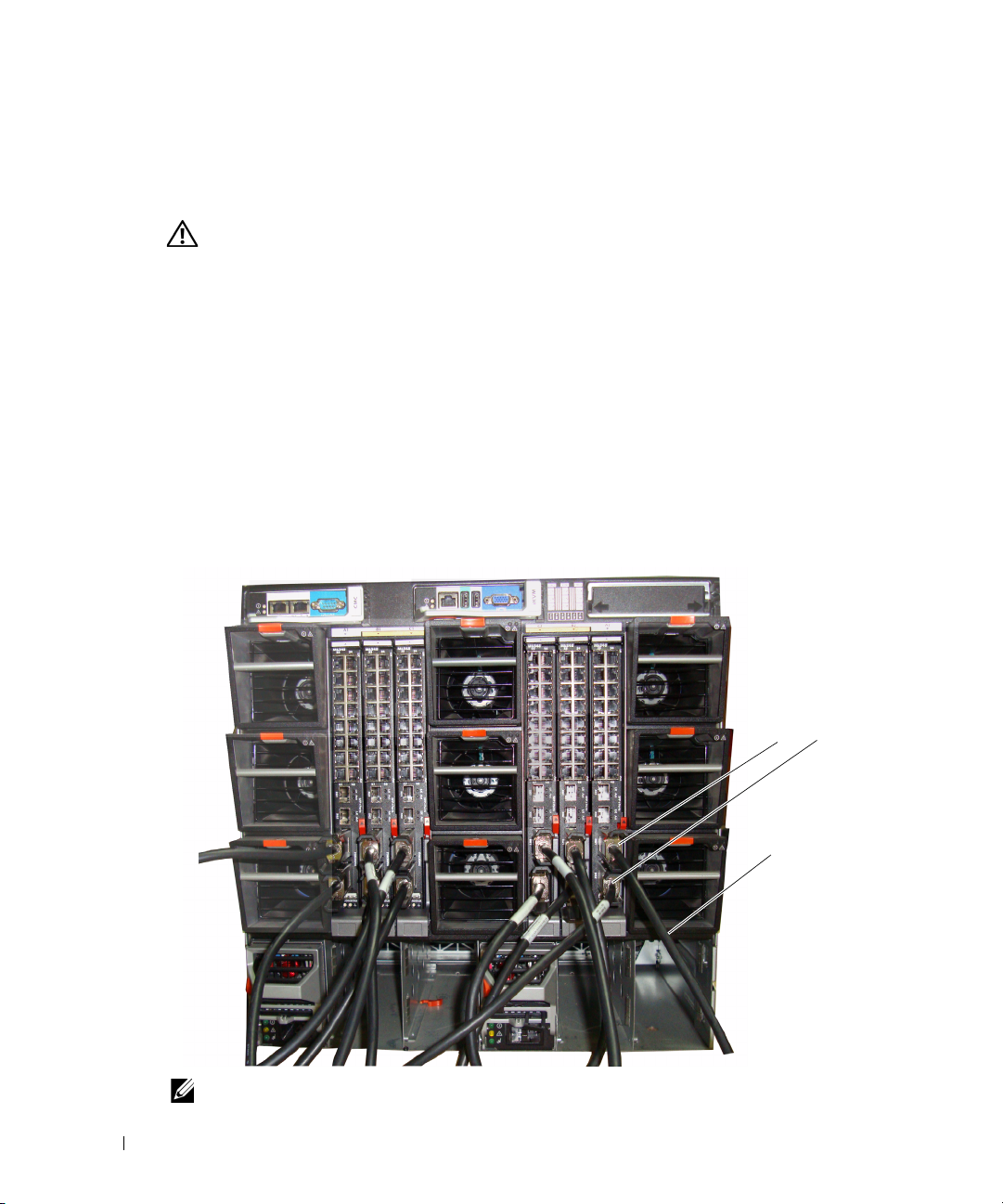
圖 1. 連接交換機堆疊
上層及下層堆疊連
接埠
堆疊纜線
註:形成的環形拓樸可讓整個堆疊用作一台具有靈活故障移轉功能的交換機。
入門指南 47
Page 50

啟動和設定交換機
完成所有外部連接之後 ,,將終端連接至交換機以設定該交換機或堆疊。
User Documentation CD 上的《使用者指南》中介紹了其他進階功能。
註:在繼續操作之前,請閱讀本產品的版本說明。可以從 Dell 支援網站 support.dell.com 下載版
本說明。
註:建議從 Dell 支援網站 support.dell.com 獲取最新版本的使用者文件。
將終端連接至交換機
www.dell.com | support.dell.com
若要透過序列主控台監控和設定交換機,請使用交換機背面的主控台連接埠,將交換機連
接至 VT100 終端或執行 VT100 終端模擬軟體的電腦。主控台連接埠可用作資料終端裝置
(DTE) 連接器。
若要使用主控台連接埠,需要滿足以下條件:
• VT100
•
執行下列工作以將終端連接至交換機主控台連接埠:
註:如果安裝的是交換機堆疊,則必須先組裝堆疊並進行纜線佈置,然後再開啟電源進行
1
2
註:在 Microsoft Windows 2000 中使用超級終端時,請確保已安裝 Windows 2000 Service Pack 2
相容終端,或者一台配備序列埠並執行
式電腦。
一根序列電纜 (附帶),帶有連接控制台埠的
設定。
將序列電纜上的
按照以下步驟設定終端模擬軟體:
a
選擇適當的序列埠 (序列埠
b
將資料速率設定為
c
將資料格式設定為
d
將流量控制設定為
e
將終端模擬模式設定為 VT100
f
對於
Terminal keys (
Windows
或更高版本。使用 Windows 2000 Service Pack 2 可以確保箭頭鍵在超級終端的 VT100 模擬中正常
工作。請瀏覽 www.microsoft.com 以獲得 Windows 2000 服務套件的更多資訊。
DB9
連接器與執行
9600
8
個資料位元、1 個停止位元以及無同位檢查。
none (無)
Function, Arrow, and Ctrl keys (
終端機按鍵)。 確保此設定適用於終端機按鍵 (而不是
®
按鍵)。
鮑。
VT100
1
或序列埠
。
。
VT100
USB A
終端模擬軟體的終端相連。
2)
以連接至主控台。
功能鍵、方向鍵和
終端模擬軟體的桌上型電腦或便攜
連接器和連接終端的
Ctrl 鍵)
DB9
連接器。
選項,請選擇
Microsoft®
48 入門指南
Page 51

3將 USB
M6348
註:如果安裝的是交換機堆疊,請將終端連接至主交換機。 交換機堆疊首次通電時,這些交換
機就會選出主交換機,主交換機可能位於堆疊中的任何位置。 如果將終端連接至成員交換機,
將無法使用 CLI。
圖 2. 連接至主控台連接埠
纜線上的
的
USB
USB A
連接器直接連接至交換機的
主控台連接埠位於背面板左側,如圖
USB
主控台連接埠。
1-2
所示。
PowerConnect
主控台連接埠
啟動交換機
請參閱《硬體使用者手冊》以瞭解啟動交換機的說明。
初始設定
註:初始的簡單設定步驟基於下列假設條件:
• PowerConnect 交換機此前從未進行過任何設定,其狀態與收到時相同。
• PowerConnect 交換機已成功啟動。
• 主控台連線已建立,並且 Dell 簡易安裝精靈提示資訊顯示在 VT100 終端或對應終端裝置的
螢幕上。
應透過主控台連接埠執行初始交換機設定。完成初始設定後,既可以透過已連接的主控台
連接埠管理交換機,也可以透過在初始設定過程中定義的介面對交換機進行遠端管理。
註:交換機未設定預設的使用者名稱和密碼。
註:若要透過遠端登入 ( 遠端登入用戶端 ) 或 HTTP (Web 瀏覽器 ) 來遠端管理交換機,需要以下
所有設定。
在設定交換機的初始組態之前,從網路管理員處獲得以下資訊:
•
要指定到管理
•
網路的
•
管理
VLAN
VLAN 的 IP
IP
子網路遮罩。
預設閘道的
IP
位址。
位址。
入門指南 49
Page 52

初始設定程序
可以使用 Dell 簡易設定精靈或指令行介面 (CLI) 來執行初始設定。當交換機設定檔為
空時,將自動啟動該設定精靈。可以隨時透過輸入 [ctrl+z] 結束精靈,但指定的所有組
態設定將被丟棄 ( 交換機將使用預設值 )。
如需 CLI 初始設定的詳細資訊,請參閱《使用者指南》。 本《入門指南》說明如何使用該
設定精靈來執行初始的交換機設定。該精靈設定交換機的以下組態:
•
建立具有權限的初始使用者帳戶及有效密碼。在設定過程中,該精靈將設定一個具有權
限的使用者帳戶。
啟用
•
•
www.dell.com | support.dell.com
•
•
•
CLI
設定管理
設定
SNMP
SNMP
管理,則可以選擇跳過這一步。
允許指定管理伺服器
設定預設閘道
範例作業階段
本節介紹一個簡單的設定精靈作業階段。範例作業階段將使用以下值:
•
要使用的
•
網路管理系統
•
使用者名稱為 admin
•
管理
VLAN 的 IP
•
預設閘道為 0.0.0.0
設定精靈根據上述定義的方式設定初始值。精靈完成後,按照以下方式設定交換機:
•
啟用
SNMPv1/2c
•
根據定義設定
•
設定網路管理系統。從該管理站可以存取
(0.0.0.0) IP
•
為預設管理
•
設定預設閘道位址。
註:在以下範例中,可能的使用者選項包括在 [ ] 中。另外,可能時,{ } 中將提供預設值。如果
未定義選項,按 <Enter> 鍵將接受預設值。說明文字在括弧中。
以下示例包含與使用上面列出的輸入值執行 Dell 簡易設定精靈範例作業階段相關的提示序
列和回應。
登入和
HTTP
VLAN 的 IP
管理員要使用的
IP
SNMP
社群字串為 DellNetworkManager
IP
存取,以便僅使用本地驗證設定。
位址。
SNMP
IP
,或允許從所有
位址。
位址為 192.168.2.1
,密碼為 admin123
位址為 192.168.2.1:255.255.255.0
。
,並按上述定義的方式設定社群字串。
admin
使用者帳戶。
位址,還可以選擇允許所有
VLAN (1) 設定 IP
位址。
社群字串 (指定了
IP
位址中進行管理存取。
。
。
。
SNMP、HTTP 及 CLI
IP
位址存取這些管理介面。
IP
位址)。如果交換機不使用
。
SNMPv3
預設停用。
介面。透過選擇
50 入門指南
Page 53

交換機完成 POST 並啟動後,將顯示以下對話資訊:
Unit 1 - Waiting to select management unit ( 單元 1 – 正在等待選擇管
理單元 )>
Applying configuration, please wait ...( 正在套用組態,請稍候 ...)
Welcome to Dell Easy Setup Wizard ( 歡迎使用 Dell 簡易安裝精靈 )
The Setup Wizard guides you through the initial switch
configuration, and gets you up and running as quickly as possible.
You can skip the setup wizard, and enter CLI mode to manually
configure the switch. You must respond to the next question to run
the setup wizard within 60 seconds, otherwise the system will
continue with normal operation using the default system
configuration.Note: You can exit the setup wizard at any point by
entering [ctrl+z]. ( 設定精靈指導您完成初始的交換機組態,讓您盡快使用交
換機。您可以跳過設定精靈,進入 CLI 模式以手動方式設定交換機。必須回答下一個
問題,在 60 秒內執行設定精靈,否則系統將繼續使用預設的系統組態正常作業。
註:可以隨時透過輸入 [ctrl+z] 鍵結束設定精靈。)
Would you like to run the setup wizard (you must answer this
question within 60 seconds)? [Y/N] y ( 要執行安裝精靈 [ 必須在 60 秒內回
答該問題 ] 嗎? [Y/N]) y
步驟 1:
The system is not setup for SNMP management by default. To manage
the switch using SNMP (required for Dell Network Manager) you can (
系統預設並未設定用於 SNMP 管理。若要使用 SNMP 管理交換機 (Dell Network
Manager 所必需 ),您可以 )
. Set up the initial SNMP version 2 account now. ( 立即設定初始的
SNMP 版本 2)。
. Return later and setup other SNMP accounts. (For more
information on setting up an SNMP version 1 or 3 account,
see the user documentation). ( 稍後返回並設定其他 SNMP 帳戶。(
如需
設定 SNMP 版本 1 或 3 帳戶的詳細資訊,請參閱使用者文件 ))。
Would you like to setup the SNMP management interface now? [Y/N] n
( 立即設定 SNMP 管理介面嗎? [Y/N]) n
入門指南 51
Page 54

步驟 2:
Now we need to setup your initial privilege (Level 15) user
account. This account is used to login to the CLI and Web
interface. You may setup other accounts and change privilege
levels later. For more information on setting up user accounts and
changing privilege levels, see the user documentation. ( 現在需要設定
初始權限 (15 級 ) 使用者帳戶。此帳戶用於登入 CLI 及 Web 介面。您稍後可以設定
其他帳戶和變更權限。如需設定使用者帳戶及變更權限的詳細資訊,請參閱使用者文件 )。
To setup a user account: ( 若要設定使用者帳戶:)
Please enter the user name. ( 請輸入使用者名稱。) [root]:root
www.dell.com | support.dell.com
Please enter the user password: ( 請輸入使用者密碼:)********
Please reenter the user password: ( 請重新輸入使用者密碼:)********
步驟 3:
Next, an IP address is setup. The IP address is defined on the
default VLAN (VLAN #1), of which all ports are members. This is the
IP address you use to access the CLI, Web interface, or SNMP
interface for the switch. Optionally you may request that the
system automatically retrieve an IP address from the network via
DHCP (this requires that you have a DHCP server running on the
network). ( 接下來設定 IP 位址。IP 位址在預設的 VLAN (VLAN #1) 上設定,
所有連接埠均為此 VLAN
SNMP 介面。您可以請求系統透過 DHCP 自動從網路擷取 IP 位址 [ 必須有 DHCP 伺服
器在網路上執行 ]。)
的成員。此 IP 位址用於存取交換機的 CLI、Web 介面或
To setup an IP address: ( 若要設定 IP 位址:)
Please enter the IP address of the device (A.B.C.D) or enter "DHCP"
(without the quotes) to automatically request an IP address from
the network DHCP server. (請輸入裝置的 IP 位址 [A.B.C.D] 或輸入 "DHCP"
[ 不帶引號 ],自動向網路 DHCP 伺服器請求 IP 位址。)
[192.168.2.1]:192.168.2.1
Please enter the IP subnet mask (A.B.C.D or /nn). ( 請輸入 IP 子網路
遮罩 (A.B.C.D 或 /nn)。) [255.255.255.0]:255.255.255.0
52 入門指南
Page 55

步驟 4:
Finally, setup the default gateway. Please enter the IP address of
the gateway from which this network is reachable. [0.0.0.0]:
( 最後設定預設閘道。請輸入網路可達的閘道之 IP 位址。[0.0.0.0]:)
This is the configuration information that has been collected:
( 以下是已收集的組態資訊:)
User Account setup ( 使用者帳戶設定 ) = root
Password = ******** ( 密碼 = ********)
Management IP address = 192.168.2.1 255.255.255.0 ( 管理 IP 位址 =
192.168.2.1 255.255.255.0)
Default Gateway = 0.0.0.0 ( 預設閘道 = 0.0.0.0)
步驟 5:
Do you want to select the operational mode as Simple Mode? ( 要選擇
作業模式為簡單模式嗎? [Y/N] n)
步驟 6:
If the information is correct, please select (Y) to save the
configuration, and copy to the start-up configuration file. If the
information is incorrect, select (N) to discard configuration and
restart the wizard: [Y/N] ( 如果資訊正確,請選擇 (Y) 儲存組態,並且複製到
啟動組態檔。如果資訊不正確,請選擇 (N) 捨棄組態並重新啟動精靈:[Y/N]) y
Thank you for using Dell Easy Set up Wizard. You will now enter CLI
mode. ( 謝謝使用 Dell 簡易設定精靈。您即將進入 CLI 模式。)
入門指南 53
Page 56

管理堆疊
主交換機與成員交換機
當交換機連接到一起時,交換機堆疊可用為單一的實體進行管理。 可以透過基於 Web
的介面、SNMP 管理站或 CLI 來管理堆疊。 建立堆疊後,其中一台交換機將自動成為主
交換機。 您可以使用主控台為主交換機手動指定 IP 位址,或讓 DHCP 自動執行此作業。
然後,可以透過主交換機的 IP 位址管理整個堆疊。 在下列情況下,主交換機將偵測並重新
設定連接埠,以最大限度地降低對執行造成的影響:
•
交換機故障
www.dell.com | support.dell.com
•
交換機間堆疊鏈路故障
•
插入交換機
•
移除交換機
如果主交換機離線,堆疊中的任何成員交換機均可取而代之。 系統將選出新的主交換機,
並為堆疊重新設定系統設定。
堆疊啟動
拓撲尋找
組成堆疊後,拓撲尋找過程將建立一個資料庫,其中包含有關堆疊中所有交換機的資訊,
包括韌體版本、硬體版本、管理喜好設定、交換機 MAC 位址和交換機序號等。 您可以使
用指令行介面 (CLI) 或 Web 介面檢視此等資訊。
註:如需 CLI 和 Web 介面的協助,請分別參閱《CLI 參考手冊》和《使用者指南》。
自動堆疊 ID 指定
在堆疊形成過程中,會給每台交換機指定一個堆疊 ID。完成堆疊 ID 指定後,每台交換
機都將其堆疊 ID 儲存到不依電性 FLASH 記憶體中。 您可以使用 CLI 或 Web 介面檢視
堆疊 ID。
檢查韌體版本
在指定堆疊 ID 之後,主交換機將執行一致性檢查,以確保堆疊中的所有交換機使用相同的
韌體版本。
如果交換機軟體版本不相符,成員交換機上的連接埠將無法有效工作。 這種情況稱為暫停
堆疊模式。 然後,您可以使用主交換機上執行的韌體來同步成員交換機上的韌體。
54 入門指南
Page 57

系統初始化
在韌體版本一致性檢查期間,如果主交換機確定所有交換機都在使用相同的韌體版本,
則該交換機將初始化為堆疊模式。
系統初始化為正常堆疊模式
主交換機將使用上一次儲存的系統設定檔來對堆疊進行初始化。 對於沒有設定檔的交
換機,系統將對它們套用預設設定。
如果設定檔已損壞,主交換機將對堆疊進行初始化,並將其設定為出廠預設組態。
您可以儲存該設定檔。 主交換機自動為成員交換機分發設定檔。 如果稍後主交換機變得無
法使用,某台成員交換機可以成為新的主交換機,並套用從原主交換機同步處理的最新設
定來設定堆疊。
系統初始化為暫停堆疊模式
系統初始化完成後,如果堆疊的韌體版本不一致,主交換機將進入暫停堆疊模式。 在此模
式下,僅使用設定檔資訊對主交換機進行初始化, 而不對任何成員交換機進行起始化。
這將強制所有成員交換機保持為非作業模式。
註:預設停用所有連接埠。
CLI/Telnet/Web 介面
您可以使用 CLI/WEB/SNMP 來同步處理主交換機中儲存的韌體與成員交換機中的韌體。
插入和移除交換機
您可以在目前堆疊中插入交換機或從中移除交換機,而無需執行電源循環。 拓樸發生變
化時,將會發生堆疊重新設定,整個網路可能會受到影響。 除非已從堆疊中移除主交
換機,否則無需重新選擇新的主交換機。 在由 12 台交換機組成的堆疊中,堆疊重新設定
過程最多需要 2 分鐘,堆疊越小,需要的時間越短。
執行為獨立交換機
如果某台交換機在用於堆疊的連接埠上偵測不到堆疊夥伴,則該交換機將作為獨立的交換
機執行。 如果偵測到堆疊夥伴,該交換機始終在堆疊模式下執行。
堆疊 ID 重新編號
您可以手動為交換機指定堆疊 ID。 一台交換機只能指定一個堆疊 ID,而且該堆疊 ID 尚未
指定給堆疊中的其他交換機。 為新堆疊 ID 儲存的任何組態資訊將套用到獲得該堆疊 ID 的
交換機。
入門指南 55
Page 58

使用者控制
使用以下 CLI 指令控制這一功能。 如需每個指令之句法的詳細資訊,請參閱《CLI 參考
手冊》。
movemanagement
reload
member
set description
switch priority
www.dell.com | support.dell.com
switch renumber
stacking
show stack-port
show stack-port counters
show stack-port diag
show switch
show supported switchtype
進階設定
本節提供有關以下常見工作的摘要資訊:
•
從
DHCP
•
安全管理和密碼設定
註:如需可用於 8024 和 8024F M6348 交換機的所有 CLI 指令之詳細資訊,請參閱《CLI 參考
指南》。
從 DHCP 伺服器擷取 IP 位址
使用 DHCP 協定擷取 IP 位址時,該交換機用作 DHCP 用戶端。
要從 DHCP 伺服器擷取 IP 位址,請執行下列步驟:
選擇任何一個連接埠並將其連接至
1
擷取
IP
註:從 DHCP 伺服器擷取 IP 位址不需要刪除交換機設定。
伺服器擷取
位址。
IP
位址
DHCP
伺服器或具有
DHCP
伺服器的子網路,以便
56 入門指南
Page 59

2
輸入以下指令,以使用選定的連接埠來獲取
console#config
console(config)#ip address dhcp
IP
位址。
介面將自動獲取
3
要驗證
IP
IP
位址。
位址,請在系統提示符後輸入
show ip interface
指令,如下例中所示。
console#show ip interface
Management Interface: ( 管理介面:)
IP Address (IP 位址 ).............................. 10.240.4.125
Subnet Mask ( 子網路遮罩 )......................... 255.255.255.0
Default Gateway ( 預設閘道 )......................... 10.240.4.1
Burned In MAC Address ( 燒錄 MAC 位址 ) ........00:10:18:82:04:35
Network Configuration Protocol Current ( 目前網路設定協定 )... DHCP
Management VLAN ID ( 管理 VLAN ID)........................... 1
Routing Interfaces: ( 路由介面:)
Netdir Multi
I
nterface IP Address IP Mask Bcast CastFwd
介面
) (IP 位址) (IP 遮罩)
(
------------- -------------- ------------ --------- ---------
vlan1 192.168.10.10 255.255.255.0 Disable (停用) Disable (停用)
vlan2 0.0.0.0 0.0.0.0 Enable (啟用) Disable (停用)
停用
loopback2 0.0.0.0 0.0.0.0 Disable (
) Disable (停用)
入門指南 57
Page 60

安全管理和密碼設定
系統安全是透過 AAA ( 驗證、授權和記帳 ) 機制進行處理的,它可以管理使用者存取
權限、特殊權限和管理方法。 AAA 使用本地和遠端使用者資料庫。 資料加密是透過 SSH
機制進行處理的。
系統在出廠時未設定預設密碼,所有密碼均由使用者定義。 如果使用者定義的密碼遺失,
則可以從 Boot ( 啟動 ) 功能表中調用密碼復原程序。 該程序僅適用於本機終端,並允許在
不輸入密碼的情況下從本機終端一次性存取交換機。
設定安全密碼
您可以為下列服務設定安全密碼:
•
www.dell.com | support.dell.com
主控台
• Telnet
• SSH
•HTTP
•HTTPS
註:建立使用者名稱時,預設的優先順序為 "1",即允許存取權限但不允許設定權限。 必須將
優先順序設定為 "15" 才能啟用對交換機的存取權限和設定權限。
設定初始主控台密碼
要設定初始主控台密碼,請輸入以下指令:
console(config)#aaa authentication login default line
•
•
58 入門指南
console(config)#aaa authentication enable default line
console(config)#line console
console(config-line)#login authentication default
console(config-line)#enable authentication default
console(config-line)#password secret123
透過主控台作業階段首次登入交換機時,請在密碼提示符後輸入 secret123
將交換機的模式變更為啟用時,請在密碼提示符後輸入 secret123
。
。
Page 61

設定初始 Telnet 密碼
要設定初始的 Telnet 密碼,請輸入以下指令:
console(config)#aaa authentication login default line
console(config)#aaa authentication enable default line
console(config)#line telnet
console(config-line)#login authentication default
console(config-line)#enable authentication default
console(config-line)#password pass1234
•
透過
Telnet
•
將交換機的模式變更為啟用時,請輸入 pass1234
設定初始 HTTP 密碼
作業階段首次登入交換機時,請在密碼提示符後輸入 pass1234
。
要設定初始 HTTP 密碼,請輸入以下指令:
console(config)#ip http authentication local
console(config)#username admin password user1234 level 15
設定初始 HTTPS 密碼
要設定初始 HTTPS 密碼,請輸入以下指令:
console(config)#ip https authentication local
。
註:您應在每次升級交換機的控制軟體應用程式 ( 安裝新版本 ) 時產生新的 crypto 證書。
設定為透過主控台、Telnet 或 SSH 作業階段使用 HTTPS 作業階段時,只需輸入一
次以下指令。
註:在 Web 瀏覽器中啟用 SSL 2.0 或更高版本以顯示頁面內容。
console(config)#crypto certificate 1 generate
console(config)#ip https server
註:Http 和 Https 服務需要的存取權限級別為 15,並直接連接至設定級別的存取。
入門指南 59
Page 62

管理交換機
您可以透過基於 Web 的介面、指令行介面 (CLI) 或 SNMP 管理交換機。 要透過 Web 瀏覽
器或 SNMP 管理交換機,交換機必須具有 IP 位址,並且必須可從管理站進行存取。 要透
過 CLI 管理交換機,可以使用直接的主控台連接或遠端 Telnet/SSH 連接。
要建立到 CLI 的直接主控台連接,請參閱第 48 頁的 「將終端連接至交換機」。 您可以使用
簡易安裝精靈執行初始設定,以允許遠端管理存取 ( 請參閱第 50 頁的「初始設定程序」 )。
如需使用 CLI 設定遠端管理的說明,請參閱 《使用者指南》。
使用 Web 瀏覽器管理交換機
www.dell.com | support.dell.com
啟動應用程式
1
開啟
Web
2
在位址欄中輸入交換機的
如需為交換機指定
3
顯示
Login (
註:交換機未設定預設密碼,可以在透過主控台連接埠連接到 CLI 時對交換機進行設定而無需
輸入密碼。 密碼區分大小寫,並且只接受英數字元。 如需復原所遺失密碼的資訊,請參閱
《使用者指南》。
4
按一下 OK (確定)。
5
系統將顯示 Dell OpenManage Switch Administrator 首頁。
瀏覽器。
IP 位址 (如 CLI
IP
位址的資訊,請參閱第
登入) 視窗時,請輸入使用者名稱和密碼。
中所定義) 並按
49
頁的 「初始設定」。
<Enter>
鍵。
瞭解介面
首頁包含以下檢視:
•
•
60 入門指南
樹狀檢視
裝置檢視
之類的資訊。
-
樹狀檢視位於首頁左側,提供了功能及其元件的可展開檢視。
-
裝置檢視位於首頁右側,用於顯示裝置的檢視、資訊或表區域和/或設定說明
Page 63

Connecteur
Dell™ PowerConnect™
M6348
Guide de mise en route
Modèle PCM6348
www.dell.com | support.dell.com
Page 64

Remarques, avis et précautions
REMARQUE : Une REMARQUE indique des informations importantes qui peuvent vous aider à mieux utiliser votre
ordinateur.
AVIS : Un AVIS vous avertit d'un risque de dommage matériel ou de perte de données et vous indique comment éviter le
problème.
PRÉCAUTION : Une PRÉCAUTION indique un risque potentiel d'endommagement du matériel, de blessure corporelle
ou de mort.
____________________
Les informations contenues dans ce document peuvent être modifiées sans préavis.
© 2009 Dell Inc. Tous droits réservés.
La reproduction de ce document de quelque manière que ce soit sans l'autorisation écrite de Dell Inc. est strictement interdite.
Marques utilisées dans ce document : Dell, le logo DELL et PowerConnect sont des marques de Dell Inc. ; Microsoft et Windows sont des
marques déposées de Microsoft Corporation.
D'autres marques et noms de marques peuvent être utilisés dans ce document pour faire référence aux entités se réclamant de ces marques et
de ces noms ou à leurs produits. Dell Inc. dénie tout intérêt propriétaire vis-à-vis des marques et des noms de marque autres que les siens.
Modèle PCM6348
Novembre 2009 N/P H851N Rév. A01
Page 65

Table des Matières
Installation
Préparation du site . . . . . . . . . . . . . . . . . . . . . . . . . . . . 65
Déballage du commutateur
Contenu du carton
Déballage
. . . . . . . . . . . . . . . . . . . . . . . . . . . . . . . 65
Connexion du commutateur à un terminal
Assemblage d'une pile
. . . . . . . . . . . . . . . . . . . . . . . . . 65
. . . . . . . . . . . . . . . . . . . . . . . . . . 65
. . . . . . . . . . . . . . . . . . 66
. . . . . . . . . . . . . . . . . . . . . . . . . . . 66
Démarrage et configuration du commutateur
Connexion du terminal au commutateur . . . . . . . . . . . . . . . . . . 68
Démarrage du commutateur
Configuration initiale
Procédure de configuration initiale
Exemple de session
. . . . . . . . . . . . . . . . . . . . . . . . 69
. . . . . . . . . . . . . . . . . . . . . . . . . . . 69
. . . . . . . . . . . . . . . . . . . 70
. . . . . . . . . . . . . . . . . . . . . . . . . . 70
Gestion d'une pile
Commutateur maître et commutateurs membres. . . . . . . . . . . . . . . 74
Démarrage de la pile
Détection de la topologie
Attribution automatique d'un ID d'empilage
Vérification de la version du micrologiciel
Initialisation du système
. . . . . . . . . . . . . . . . . . . . . . . . . . . . 74
. . . . . . . . . . . . . . . . . . . . . . . 74
. . . . . . . . . . . . . . . 74
. . . . . . . . . . . . . . . 75
. . . . . . . . . . . . . . . . . . . . . . . . 75
Interfaces CLI/Telnet/Web
. . . . . . . . . . . . . . . . . . . . . . . . . 75
Insertion et retrait de commutateurs
Fonctionnement en mode autonome
Réattribution des ID d'empilage
Commandes utilisateur
. . . . . . . . . . . . . . . . . . . . . . . . . . . 76
. . . . . . . . . . . . . . . . . . 75
. . . . . . . . . . . . . . . . . . 76
. . . . . . . . . . . . . . . . . . . . 76
63
Page 66

Configuration avancée . . . . . . . . . . . . . . . . . . . . . . . . . . . 77
Obtention d'une adresse IP à partir d'un serveur DHCP
Gestion de la sécurité et configuration du mot de passe
. . . . . . . . . 77
. . . . . . . . . 78
Gestion du commutateur
Utilisation d'un navigateur Web pour gérer le commutateur . . . . . . . . . 81
Démarrage de l'application
Présentation de l'interface
. . . . . . . . . . . . . . . . . . . . . . 81
. . . . . . . . . . . . . . . . . . . . . . 81
64
Page 67

Installation
Ce document contient des informations de base sur l'installation, la configuration et le
fonctionnement des systèmes Dell™ PowerConnect™ M6348. Pour obtenir des informations plus
détaillées, voir le
CD
User Documentation
site
support.dell.com
documentation et au micrologiciel.
Préparation du site
Avant d'installer le commutateur, assurez-vous que le site choisi pour l'installation répond aux
conditions définies dans le document
Déballage du commutateur
Contenu du carton
Lors du déballage de chaque commutateur, vérifiez que le carton contient les éléments suivants :
• Un commutateur PowerConnect
• Un câble série USB de type A vers DB9
•Le CD
• Guide de mise en route
• Le guide d'information sur le produit
Hardware Owner's Manual
(Documentation utilisateur). Vous pouvez également vous rendre sur le
pour prendre connaissance des dernières mises à jour apportées à la
User Documentation
(Manuel du propriétaire), que vous trouverez sur le
Hardware Owner's Manual
(Documentation utilisateur)
(Manuel du propriétaire).
Déballage
REMARQUE : Avant de déballer le commutateur, examinez le carton d'emballage et signalez
immédiatement tout dommage apparent.
Posez le carton sur une surface plane et propre et coupez toutes les sangles d'attache.
1
2
Ouvrez le carton ou retirez le couvercle.
3
Retirez avec précaution le commutateur de son carton et posez-le sur une surface propre et
stable.
4
Retirez tout le matériel d'emballage.
5
Vérifiez que le produit et ses accessoires ne sont pas endommagés.
Guide de mise en route 65
Page 68

Connexion du commutateur à un terminal
1
Branchez le connecteur DB9 du câble série de type RJ-45 au terminal VT100 ou un
ordinateur exécutant un logiciel d'émulation de terminal VT100.
2
Branchez le connecteur USB situé à l'autre extrémité du câble sur le port USB du
commutateur.
REMARQUE : Si vous installez une pile de commutateurs, connectez le terminal au commutateur
maître. Lorsqu'une pile est mise sous tension pour la première fois, l'un des commutateurs est désigné
comme maître de la pile. Ce commutateur peut occuper n'importe quel emplacement. Si vous connectez
le terminal à un commutateur autre que le commutateur maître, vous ne pourrez pas utiliser l'interface
de ligne de commande (CLI).
www.dell.com | support.dell.com
Assemblage d'une pile
Les logiciels prennent en charge un maximum de 12 commutateurs par pile, soit un total de
576 ports 1G. Chaque commutateur PowerConnect M6348 est équipé de deux ports d'empilage
situés en bas du commutateur.
PRÉCAUTION : Les commutateurs doivent toujours être éteints lorsque vous les ajoutez à la pile.
Utilisez des câbles d'empilage d'un mètre de longueur pour connecter les ports d'empilage comme
suit :
1
Insérez un câble d'empilage dans le port d'empilage situé en bas du premier commutateur.
2
Branchez le câble sur le port d'empilage supérieur du second commutateur.
3
Connectez chaque commutateur avec le suivant jusqu'à ce que tous les commutateurs soient
reliés en anneau.
4
Sur le dernier commutateur de la pile, connectez le câble avec le port d'empilage supérieur du
premier commutateur afin de créer une boucle.
Au besoin, utilisez un câble d'empilage de 3 mètres (non fourni) pour connecter le dernier
commutateur avec le premier.
66 Guide de mise en route
Page 69

La figure 1 affiche un châssis de six commutateurs M6348 connectés.
Figure 1. Connexion d'une pile de commutateurs
Câbles d'empilage
supérieurs et
inférieurs
câble d'empilage
REMARQUE : La topologie en anneau ainsi créée permet à la pile de fonctionner comme un
commutateur unique doté de capacités de prise de relais.
Guide de mise en route 67
Page 70

Démarrage et configuration du commutateur
Une fois toutes les connexions externes établies, connectez un terminal à un commutateur en vue
de configurer le commutateur ou la pile. Les fonctions supplémentaires disponibles sont décrites
dans le document
(Documentation utilisateur).
REMARQUE : Avant de continuer, lisez les notes d'édition concernant ce produit. Vous pouvez
les télécharger à partir du site d'assistance technique de Dell, support.dell.com.
REMARQUE : Nous vous recommandons de vous procurer la version la plus récente de
la documentation utilisateur disponible sur le site support.dell.com.
www.dell.com | support.dell.com
Connexion du terminal au commutateur
Pour gérer et configurer le commutateur à partir d'une console série, utilisez le port de console situé
à l'arrière de l'appareil pour le relier à un terminal VT100 ou à un système exécutant un logiciel
d'émulation de terminal VT100. Le port de console est un connecteur DTE (Data Terminal
Equipment, Équipement de terminal de données).
Pour utiliser le port de console, vous devez disposer des équipements suivants :
• Terminal compatible VT100 ou ordinateur (de bureau ou portable) équipé d'un port série et
exécutant un logiciel d'émulation de terminal VT100.
• Câble série (fourni) doté d'un connecteur RJ-45 pour le port de console et d'un
connecteur DB9 pour le terminal.
Pour connecter un terminal au port de console du commutateur, procédez comme suit :
User's Guide
(Guide d'utilisation), qui se trouve sur le CD
User Documentation
REMARQUE : Si vous installez une pile de commutateurs, vous devez terminer son assemblage et son
câblage avant de la mettre sous tension et de la configurer.
Enfichez le connecteur DB9 du câble série sur le terminal exécutant le logiciel d'émulation de
1
terminal VT100.
2
Configurez le logiciel d'émulation de terminal comme suit :
a
Sélectionnez le port série approprié (1 ou 2) pour la connexion à la console.
b
Réglez le débit de données sur 9600 bauds.
c
Paramétrez le format de données sur 8 bits de données, 1 bit d'arrêt et aucune parité.
d
Définissez le contrôle de flux sur "none" (aucun).
e
Réglez le mode d'émulation de terminal sur
f
Choisissez l'option "Touches de terminal" dans le champ "Les touches de fonction, de
direction et Ctrl agissent en tant que". Vérifiez que le paramétrage correspond bien à
"Touches de terminal" et non à "Touches Microsoft
68 Guide de mise en route
VT100
.
®
Windows®".
Page 71

REMARQUE : Si vous utilisez HyperTerminal sous Microsoft Windows 2000, assurez-vous que le
Service Pack 2 (ou suivant) du système d'exploitation est installé. Ce service pack permet aux touches
fléchées de fonctionner correctement dans l'émulation VT100 d'HyperTerminal. Pour plus d'informations
concernant les services pack Windows 2000, rendez-vous sur le site www.microsoft.com.
Enfichez le USB de type ARJ-45 directement sur le port de console USB. Le port de la console
3
PowerConnect 8024 et 8024F est situé à gauche du panneau arrière, comme indiqué dans la
figure 2.
REMARQUE : Si vous installez une pile de commutateurs, c²onnectez le terminal au commutateur
maître. Lorsqu'une pile est mise sous tension pour la première fois, l'un des commutateurs est désigné
comme maître de la pile. Ce commutateur peut occuper n'importe quel emplacement. Si vous connectez
le terminal à un commutateur autre que le commutateur maître, vous ne pourrez pas utiliser l'interface
de ligne de commande (CLI).
Figure 2. Connexion au port de console
Port
de console
Démarrage du commutateur
Pour obtenir des informations sur le démarrage du commutateur, voir le document
Owner's Manual
(Manuel du propriétaire).
Hardware
Configuration initiale
REMARQUE : La procédure de configuration initiale est fondée sur les hypothèses suivantes :
• Le commutateur PowerConnect n'a jamais été configuré auparavant et n'a pas été modifié
depuis que vous l'avez reçu.
• Le commutateur PowerConnect a démarré correctement.
• La connexion à la console est établie et l'invite de l'assistant Dell Easy Setup est affichée sur l'écran
d'un terminal VT100 ou équivalent.
La configuration initiale du commutateur est effectuée via le port de console. Une fois cette
première étape effectuée, le commutateur peut être géré soit à partir de la console connectée,
soit à distance, via une interface définie lors de la configuration initiale.
Guide de mise en route 69
Page 72

REMARQUE : Le commutateur ne possède pas de nom d'utilisateur ni de mot de passe par défaut.
REMARQUE : Tous les paramètres suivants sont nécessaires pour permettre la gestion à distance du
commutateur via Telnet (client Telnet) ou HTTP (navigateur Web).
Avant de procéder à la configuration initiale du commutateur, demandez les informations
suivantes à votre administrateur réseau :
• Adresse IP à affecter au VLAN de gestion
• Masque de sous-réseau IP
• Adresse IP correspondant à la passerelle par défaut du VLAN de gestion
Procédure de configuration initiale
www.dell.com | support.dell.com
Vous pouvez effectuer la configuration initiale à l'aide de l'interface CLI ou de l'Assistant Dell Easy
Setup. Cet assistant démarre automatiquement si le fichier de configuration du commutateur est
vide. Vous pouvez quitter l'assistant à tout moment en tapant [ctrl+z]. Dans ce cas, tous les
paramètres de configuration modifiés sont supprimés et le commutateur utilise les valeurs par
défaut.
Pour plus d'informations sur la configuration initiale CLI, voir le document
(Guide d'utilisation). Seule l'utilisation de
L'assistant effectue les opérations suivantes :
• Il met en place le compte utilisateur privilégié initial et le mot de passe correspondant.
Cette opération est effectuée pendant la configuration.
• Il permet l'ouverture de session via l'interface CLI et l'accès HTTP (authentification locale
uniquement).
• Il permet de définir l'adresse IP pour le VLAN de gestion.
• Il définit la chaîne de communauté SNMP qui doit être utilisée par le gestionnaire SNMP sur
une adresse IP donnée. Vous pouvez ignorer cette étape si le commutateur n'est pas géré via
SNMP.
• Il permet d'indiquer l'adresse IP du serveur de gestion ou d'autoriser l'accès aux fonctions de
gestion à partir de toutes les adresses IP.
• Il configure l'adresse IP de la passerelle par défaut.
User Guide
l'assistant est décrite dans le présent document.
Exemple de session
Cette section illustre une session de l'assistant Easy Setup. Les valeurs suivantes sont utilisées :
• Chaîne de communauté SNMP à utiliser :
• Adresse IP du système de gestion du réseau :
• Nom d'utilisateur :
• Adresse IP du VLAN de gestion :
• Passerelle par défaut :
70 Guide de mise en route
admin
0.0.0.0
DellNetworkManager
192.168.2.1
; mot de passe :
admin123
.
192.168.2.1:255.255.255.0
.
.
.
.
Page 73

L'assistant définit les valeurs initiales comme indiqué ci-dessus. Une fois son exécution terminée,
le commutateur est configuré de la façon suivante :
• SNMPv1/2c est activé et la chaîne de communauté est définie comme indiqué ci-dessus.
SNMPv3 est désactivé par défaut.
• Le compte utilisateur admin est configuré comme indiqué ci-dessus.
• Un système de gestion du réseau est configuré. À partir de cette station de gestion, vous
pouvez accéder aux interfaces SNMP, HTTP et CLI. Vous pouvez également décider
d'autoriser toutes les adresses IP à accéder à ces interfaces de gestion. Pour ce faire, indiquez
l'adresse IP 0.0.0.0.
• Une adresse IP est configurée pour le VLAN de gestion par défaut (1).
• Une adresse de passerelle par défaut est configurée.
REMARQUE : Dans l'exemple ci-après, les options que l'utilisateur peut sélectionner sont présentées
entre crochets. Les valeurs par défaut sont présentées entre accolades { }. Si vous appuyez sur
<Entrée> sans avoir défini d'options, la valeur par défaut est prise en compte. Le texte de l'aide est entre
parenthèses.
L'exemple suivant montre une suite d'invites et de réponses affichées dans l'assistant Dell Easy
Setup. Les valeurs utilisées sont indiquées ci-dessus.
Au démarrage du commutateur (après l'auto-test de démarrage), la boîte de dialogue suivante
s'affiche :
(Unit 1 - Waiting to select management unit)>
Applying configuration, please wait ...
Welcome to Dell Easy Setup Wizard
The Setup Wizard guides you through the initial switch
configuration, and gets you up and running as quickly as possible.
You can skip the setup wizard, and enter CLI mode to manually
configure the switch. You must respond to the next question to run
the setup wizard within 60 seconds, otherwise the system will
continue with normal operation using the default system
configuration.Note: You can exit the setup wizard at any point by
entering [ctrl+z].
Would you like to run the setup wizard (you must answer this
question within 60 seconds)? [Y/N] y
Guide de mise en route 71
Page 74

Étape1:
The system is not setup for SNMP management by default. To manage
the switch using SNMP (required for Dell Network Manager) you can:
. Set up the initial SNMP version 2 account now.
. Return later and setup other SNMP accounts. (For more
information on setting up an SNMP version 1 or 3 account, see
the user documentation).
Would you like to setup the SNMP management interface now? [Y/N] n
Étape2:
www.dell.com | support.dell.com
Now we need to setup your initial privilege (Level 15) user
account. This account is used to login to the CLI and Web
interface. You may setup other accounts and change privilege
levels later. For more information on setting up user accounts and
changing privilege levels, see the user documentation.
To setup a user account:
Please enter the user name. [root] :root
Please enter the user password:********
Please reenter the user password:********
Étape 3 :
Next, an IP address is setup. The IP address is defined on the
default VLAN (VLAN #1), of which all ports are members. This is the
IP address you use to access the CLI, Web interface, or SNMP
interface for the switch. Optionally you may request that the
system automatically retrieve an IP address from the network via
DHCP (this requires that you have a DHCP server running on the
network).
To setup an IP address:
Please enter the IP address of the device (A.B.C.D) or enter "DHCP"
(without the quotes) to automatically request an IP address from
the network DHCP server. [192.168.2.1]:192.168.2.1
Please enter the IP subnet mask (A.B.C.D or /nn).
[255.255.255.0]:255.255.255.0
72 Guide de mise en route
Page 75

Étape 4 :
Finally, setup the default gateway. Please enter the IP address of
the gateway from which this network is reachable. [0.0.0.0]:
This is the configuration information that has been collected:
User Account setup = root
Password = **********
Management IP address = 192.168.2.1 255.255.255.0
Default Gateway = 0.0.0.0
Étape 5 :
Do you want to select the operational mode as Simple Mode? [Y/N] n
Étape 6 :
If the information is correct, please select (Y) to save the
configuration, and copy to the start-up configuration file. If the
information is incorrect, select (N) to discard configuration and
restart the wizard: [Y/N] y
Thank you for using Dell Easy Set up Wizard. You will now enter CLI
mode.
Guide de mise en route 73
Page 76

Gestion d'une pile
Commutateur maître et commutateurs membres
Une pile de commutateurs peut être gérée comme une entité unique lorsque les unités qui la
composent sont connectées les unes aux autres. La pile peut être gérée via une interface web, une
station de gestion SNMP ou une interface CLI. Lorsque la pile est créée, l'un des commutateurs
est automatiquement désigné comme maître. Vous pouvez alors lui attribuer une adresse IP
manuellement en utilisant la console, ou laisser DHCP s'en charger automatiquement. Par la suite,
l'adresse IP du commutateur maître est utilisée pour gérer la pile dans son intégralité.
www.dell.com | support.dell.com
Le commutateur maître détecte et reconfigure les ports avec un impact minimal sur le
fonctionnement de la pile dans les cas suivants :
• Panne d'un commutateur
• Perte de la liaison entre les commutateurs
• Insertion d'un commutateur
• Retrait d'un commutateur
Si le commutateur maître est déconnecté, n'importe quel commutateur membre de la pile peut
le remplacer. Le système désigne un nouveau commutateur maître et reconfigure la pile en
conséquence.
Démarrage de la pile
Détection de la topologie
Lorsqu'une pile est créée, un processus de détection de la topologie génère une base de données
contenant des informations sur tous les commutateurs de la pile : version du micrologiciel,
du matériel, préférences de gestion, adresse MAC et numéro de série. Vous pouvez afficher ces
informations à l'aide de l'interface de ligne de commande (CLI) ou de l'interface Web.
REMARQUE : Reportez-vous respectivement aux documents CLI Reference Manual (Manuel de
référence CLI) et User's Guide (Guide d'utilisation) pour plus d'informations sur les interfaces CLI et Web.
Attribution automatique d'un ID d'empilage
Lors du processus de formation de la pile, chaque commutateur se voit attribuer un ID d'empilage
qu'il enregistre ensuite dans sa mémoire FLASH rémanente. Vous pouvez afficher les ID
d'empilage à l'aide de l'interface CLI ou de l'interface Web.
74 Guide de mise en route
Page 77

Vérification de la version du micrologiciel
Une fois l'attribution des ID d'empilage terminée, le commutateur maître vérifie que tous les
commutateurs de la pile exécutent la même version du micrologiciel.
Si tel n'est pas le cas, les ports des commutateurs membres ne pourront pas fonctionner. La pile est
alors en mode SSM (Suspended Stacking Mode). Vous pouvez ensuite synchroniser les logiciels des
commutateurs membres avec ceux du commutateur maître.
Initialisation du système
Si le commutateur maître détecte que toutes les unités disposent de la même version du
micrologiciel, il est initialisé pour le fonctionnement en mode d'empilage.
Initialisation du système en mode d'empilage standard
Le commutateur maître initialise la pile en utilisant le dernier fichier de configuration système
enregistré. Le système applique les paramètres par défaut aux commutateurs ne disposant pas de
fichier de configuration.
Si le fichier de configuration est endommagé, le commutateur maître initialise la pile avec la
configuration par défaut définie en usine.
Le fichier de configuration peut être enregistré. Le commutateur maître distribue le fichier de
configuration automatiquement aux commutateurs membres. S'il est indisponible, un autre
commutateur prend sa place et configure la pile en utilisant la configuration la plus récente
synchronisée à partir du commutateur maître.
Initialisation du système en mode SSM
Une fois l'initialisation terminée, si des incohérences subsistent entre les versions du micrologiciel
des différentes unités de la pile, le commutateur maître passe en mode SSM. Il est alors le seul à
être initialisé avec les informations du fichier de configuration. Les commutateurs membres ne
sont pas initialisés et restent en mode passif.
REMARQUE : Tous les ports sont désactivés par défaut.
Interfaces CLI/Telnet/Web
Vous pouvez utiliser les interfaces CLI, WEB ou SNMP pour synchroniser un commutateur
membre avec le micrologiciel stocké sur le commutateur maître.
Insertion et retrait de commutateurs
Vous pouvez insérer et retirer des commutateurs de la pile sans mettre cette dernière hors tension.
Cependant, toute modification de la topologie entraînant une reconfiguration de la pile peut avoir
un impact sur le réseau. Aucun commutateur n'est alors désigné comme commutateur maître, à
moins que celui-ci n'ait été retiré de la pile. La reconfiguration de la pile ne prend pas plus de deux
minutes pour une pile de douze commutateurs, voire moins pour une pile plus petite.
Guide de mise en route 75
Page 78

Fonctionnement en mode autonome
Si aucun partenaire n'est détecté sur le port d'empilage d'un commutateur, ce dernier fonctionne
en mode autonome. Dans le cas contraire, le commutateur opère toujours en mode d'empilage.
Réattribution des ID d'empilage
Vous pouvez attribuer manuellement un ID d'empilage à un commutateur. L'ID d'empilage
attribué à un commutateur ne doit avoir été associé à aucun autre commutateur de la pile. Toutes
les informations de configuration enregistrées pour le nouvel ID d'empilage s'appliquent au
commutateur correspondant.
www.dell.com | support.dell.com
Commandes utilisateur
Les commandes suivantes permettent de gérer le commutateur via l'interface CLI. Reportez-vous
au document
chaque commande.
movemanagement
reload
member
set description
switch priority
switch renumber
stacking
show stack-port
show stack-port counters
show stack-port diag
show switch
show supported switchtype
CLI Reference Manual
(Guide de CLI) pour plus d'informations sur la syntaxe de
76 Guide de mise en route
Page 79

Configuration avancée
Cette section présente des informations récapitulatives sur des tâches courantes telles que les
suivantes :
• Obtention d'une adresse IP à partir d'un serveur DHCP
• Gestion de la sécurité et configuration du mot de passe
REMARQUE : Pour obtenir des informations détaillées sur les commandes CLI disponibles pour les
commutateurs de la série 8024, 8024F et M6348, voir le document CLI Reference Guide (Guide de
référence CLI).
Obtention d'une adresse IP à partir d'un serveur DHCP
Lorsque le protocole DHCP est utilisé pour obtenir une adresse IP, le commutateur agit en tant
que client DHCP.
Pour obtenir une adresse IP à partir d'un serveur DHCP, procédez comme suit :
1
Sélectionnez et connectez n'importe quel port à un serveur DHCP ou à un sous-réseau
possédant un serveur DHCP, de manière à obtenir l'adresse IP.
REMARQUE : Il n'est pas nécessaire de supprimer la configuration du commutateur pour obtenir une
adresse IP du serveur DHCP.
2
Entrez les commandes ci-dessous pour utiliser le port sélectionné pour la réception de
l'adresse IP.
console#config
console(config)#ip address dhcp
L'interface reçoit automatiquement l'adresse IP.
3
Pour vérifier l'adresse IP, entrez la commande show ip interface à l'invite du système, comme
indiqué dans l'exemple suivant.
console#show ip interface
Management Interface:
IP Address....................................... 10.240.4.125
Subnet Mask..................................... 255.255.255.0
Default Gateway.................................... 10.240.4.1
Burned In MAC Address........................00:10:18:82:04:35
Network Configuration Protocol Current................... DHCP
Management VLAN ID.......................................... 1
Guide de mise en route 77
Page 80

Routing Interfaces:
Interface Adresse IP Masque IP Bcast CastFwd
---------- --------------- --------------- -------- --------
vlan1 192.168.10.10 255.255.255.0 Disable Disable
vlan2 0.0.0.0 0.0.0.0 Enable Disable
loopback2 0.0.0.0 0.0.0.0 Disable Disable
Gestion de la sécurité et configuration du mot de passe
www.dell.com | support.dell.com
La sécurité du système est contrôlée via le mécanisme AAA (Authentication, Authorization,
Accounting) qui gère les droits d'accès des utilisateurs, les privilèges et les méthodes de gestion.
AAA fait appel à des bases de données utilisateur à la fois locales et distantes. Le cryptage des
données est traité via le mécanisme SSH.
Le système est livré sans mot de passe par défaut. Les mots de passe sont tous définis par
l'utilisateur. Si un mot de passe défini par l'utilisateur est perdu, une procédure de récupération du
mot de passe peut être lancée à partir du menu Boot (Amorçage). Cette procédure est applicable
uniquement sur le terminal local et permet d'accéder une seule fois au commutateur sans saisir de
mot de passe.
Configuration de mots de passe de sécurité
Vous pouvez configurer des mots de passe de sécurité pour les services suivants :
•Console
• Telnet
• SSH
•HTTP
•HTTPS
Netdir Multi
REMARQUE : Lors de la création d'un nom d'utilisateur, la priorité par défaut est "1", ce qui signifie que
l'utilisateur peut accéder au système mais pas aux fonctions de configuration. L'accès à la configuration
n'est possible que si le niveau de priorité "15" est défini.
78 Guide de mise en route
Page 81

Configuration d'un mot de passe de console initial
Pour configurer un mot de passe de console initial, entrez les commandes suivantes :
console(config)#aaa authentication login default line
console(config)#aaa authentication enable default line
console(config)#line console
console(config-line)#login authentication default
console(config-line)#enable authentication default
console(config-line)#password secret123
• Lorsque vous vous connectez pour la première fois à un commutateur à partir d'une session
de console, entrez
secret123
• Lorsque vous activez le mode "enable" sur le commutateur, tapez
à l'invite du mot de passe.
secret123
à l'invite du
mot de passe.
Configuration d'un mot de passe Telnet initial
Pour configurer un mot de passe Telnet initial, entrez les commandes suivantes :
console(config)#aaa authentication login default line
console(config)#aaa authentication enable default line
console(config)#line telnet
console(config-line)#login authentication default
console(config-line)#enable authentication default
console(config-line)#password pass1234
• Lorsque vous vous connectez à un commutateur pour la première fois via une session Telnet,
pass1234
tapez
• Lorsque vous activez le mode "enable" sur le commutateur, tapez
à l'invite du mot de passe.
pass1234
à l'invite du
mot de passe.
Configuration d'un mot de passe HTTP initial
Pour configurer un mot de passe HTTP initial, entrez les commandes suivantes :
console(config)#ip http authentication local
console(config)#username admin password user1234 level 15
Guide de mise en route 79
Page 82

Configuration d'un mot de passe HTTPS initial
Pour configurer un mot de passe HTTPS, entrez les commandes suivantes :
console(config)#ip https authentication local
REMARQUE : Vous devez générer un nouveau certificat de cryptographie à chaque fois que vous
mettez à niveau le logiciel de contrôle du commutateur.
Entrez les commandes ci-dessous une fois lorsque vous configurez l'utilisation d'une
session HTTPS via une console, Telnet ou SSH.
REMARQUE : Dans le navigateur Web, activez SSL version 2.0 ou supérieure afficher le contenu de la
page.
console(config)#crypto certificate 1 generate
www.dell.com | support.dell.com
console(config)#ip https server
REMARQUE : Les services http et https nécessitent un privilège de niveau 15 et permettent un accès
direct aux fonctions de configuration.
80 Guide de mise en route
Page 83

Gestion du commutateur
Vous pouvez gérer le commutateur à l'aide de l'interface web, l'interface de ligne de commande
(CLI), ou SNMP. Pour gérer le commutateur à l'aide du navigateur Web ou SNMP, le commutateur
doit avoir une adresse IP et doit être accessible à partir de la station de gestion. Pour gérer le
commutateur à l'aide de l'interface CLI, vous pouvez utiliser une connexion directe avec le port de
la console ou par l'intermédiaire d'une connexion à distance Telnet/SSH.
Pour établir une connexion directe à l'interface CLI avec le port de la console, consulter
"Connexion du terminal au commutateur", page 68. Vous pouvez effectuer la configuration initiale
à l'aide de l'Assistant Easy Setup qui permet d'accéder à la gestion à distance (consulter "Procédure
de configuration initiale", page 70). Pour obtenir des instructions sur la configuration de la gestion
à distance via l'interface CLI, consulter le document
Utilisation d'un navigateur Web pour gérer le commutateur
Démarrage de l'application
1
Ouvrez un navigateur Web.
2
Tapez l'adresse IP du commutateur (définie via l'interface CLI) dans la barre d'adresse, puis
appuyez sur <Entrée>.
Pour savoir comment définir l'adresse IP d'un commutateur, voir "Configuration initiale",
page 69.
3
Lorsque la fenêtre Login (Ouverture de session) s'affiche, entrez un nom d'utilisateur et un
mot de passe.
User’s Guide
(Guide d'utilisation).
REMARQUE : Le commutateur n'est associé à aucun mot de passe par défaut. Vous pouvez configurer
le commutateur sans entrer de mot de passe lorsque vous vous connectez à l'interface CLI par
l'intermédiaire du port de console. Les mots de passe sont sensibles à la casse et doivent contenir des
caractères alphanumériques. Pour plus d'informations sur la récupération des mots de passe oubliés,
consulter le document User’s Guide(Guide d'utilisation).
Cliquez sur OK.
4
5
La page d'accueil de
Dell OpenManage Switch Administrator
s'affiche.
Présentation de l'interface
La page d'accueil offre différents modes d'affichage :
• Vue Arborescence : affichée dans le volet gauche de la page d'accueil, cette vue fournit une
représentation hiérarchisée des différentes fonctionnalités et de leurs composants.
• Vue du périphérique : située dans le volet droit de la page d'accueil, cette vue contient une
représentation graphique du périphérique, une zone d'informations et/ou un tableau et/ou
des instructions de configuration.
Guide de mise en route 81
Page 84

www.dell.com | support.dell.com
82 Guide de mise en route
Page 85

Dell™ PowerConnect™
M6348 Switch
Handbuch zum Einstieg
Modelle PCM6348
www.dell.com | support.dell.com
Page 86

Anmerkungen, Hinweise und Vorsichtshinweise
ANMERKUNG: Eine ANMERKUNG macht auf wichtige Informationen aufmerksam, mit denen Sie das System besser
einsetzen können.
HINWEIS: Ein HINWEIS warnt vor möglichen Beschädigungen der Hardware oder vor Datenverlust und zeigt auf, wie
derartige Probleme vermieden werden können.
VORSICHT: Hiermit werden Sie auf eine potenziell gefährliche Situation hingewiesen, die zu Sachschäden,
Verletzungen oder zum Tod führen könnte.
____________________
Irrtümer und technische Änderungen vorbehalten.
© 2009 Dell Inc. Alle Rechte vorbehalten.
Nachdrucke jeglicher Art ohne die vorherige schriftliche Genehmigung von Dell Inc. sind strengstens untersagt.
In diesem Text verwendete Marken: Dell, das DELL Logo und PowerConnect sind Marken von Dell Inc.; Microsoft und Windows sind
eingetragene Marken von Microsoft Corporation.
Alle anderen in dieser Dokumentation genannten Marken und Handelsnamen sind Eigentum der jeweiligen Hersteller und Firmen. Dell Inc.
erhebt keinen Anspruch auf Besitzrechte an Marken und Handelsbezeichnungen mit Ausnahme der eigenen.
Modelle PCM6348
November 2009 Teilenr. H851N Rev. A01
Page 87

Inhalts
Installation
Standortvorbereitung . . . . . . . . . . . . . . . . . . . . . . . . . . . 87
Auspacken des Switches
Inhalt der Verpackung
Auspacken
. . . . . . . . . . . . . . . . . . . . . . . . . . . . . . 87
Verbinden eines Switches mit einem Terminal
Zusammenfügen eines Stacks
. . . . . . . . . . . . . . . . . . . . . . . . . 87
. . . . . . . . . . . . . . . . . . . . . . . . . 87
. . . . . . . . . . . . . . . 88
. . . . . . . . . . . . . . . . . . . . . . . 88
Starten und Konfigurieren des Switches
Verbinden des Terminals mit dem Switch . . . . . . . . . . . . . . . . . . 90
Starten des Switches
Erstkonfiguration
Durchführen der Erstkonfiguration
Beispielhafter Ablauf
. . . . . . . . . . . . . . . . . . . . . . . . . . . 91
. . . . . . . . . . . . . . . . . . . . . . . . . . . . . 91
. . . . . . . . . . . . . . . . . . . 92
. . . . . . . . . . . . . . . . . . . . . . . . . 92
Verwalten eines Stacks
Master- und untergeordnete Switches . . . . . . . . . . . . . . . . . . . 96
Stack-Start
. . . . . . . . . . . . . . . . . . . . . . . . . . . . . . . . 96
Topologie-Erkennung
Automatische Zuweisung von Stack-IDs
Firmware-Versionsüberprüfung
Systeminitialisierung
. . . . . . . . . . . . . . . . . . . . . . . . . 96
. . . . . . . . . . . . . . . . 96
. . . . . . . . . . . . . . . . . . . . 97
. . . . . . . . . . . . . . . . . . . . . . . . . 97
Befehlszeilen-/Telnet-/Web-Schnittstelle
Hinzufügen und Entfernen von Switches
Betrieb als eigenständiger Switch
Ändern der Stack-ID
. . . . . . . . . . . . . . . . . . . . . . . . . 98
Vom Benutzer ausführbare Steuerbefehle
. . . . . . . . . . . . . . . . . . 98
. . . . . . . . . . . . . . . . 98
. . . . . . . . . . . . . . . . . . . 98
. . . . . . . . . . . . . . . . . . 99
85
Page 88

Fortgeschrittene Konfiguration . . . . . . . . . . . . . . . . . . . . . . . 99
Abrufen einer IP-Adresse von einem DHCP-Server
Sicherheitsverwaltung und Kennwortkonfiguration
. . . . . . . . . . . 99
. . . . . . . . . . 101
Switch-Verwaltung
Verwalten des Switches über einen Web-Browser . . . . . . . . . . . . 103
Starten der Anwendung
Aufbau der Benutzeroberfläche
. . . . . . . . . . . . . . . . . . . . . . . 103
. . . . . . . . . . . . . . . . . . . 103
86
Page 89

Installation
Dieses Dokument enthält grundlegende Informationen zu Installation, Konfiguration und Betrieb
von Dell™ PowerConnect™ M6348-Systemen. Weitere Informationen finden Sie im auf der CD
User Documentation
Firmware erhalten Sie auf der Dell Support-Website unter
Standortvorbereitung
Vergewissern Sie sich vor der Installation des Switches, dass der gewählte Standort die im
Hardware-Benutzerhandbuch
Auspacken des Switches
Inhalt der Verpackung
Kontrollieren Sie beim Auspacken der einzelnen Switches, ob jeweils die folgenden Teile
vorhanden sind:
• Ein PowerConnect-Switch
• Ein Kabel von USB Typ A auf DB9 seriell
User Documentation
•
• Handbuch zum Einstieg
• Produktinformationshandbuch
(Benutzerdokumentation). Aktuelle Updates von Dokumentation und
support.dell.com
angegebenen Anforderungen erfüllt.
-CD (Benutzerdokumentation)
.
Auspacken
ANMERKUNG: Überprüfen Sie vor dem Auspacken des Switches die Verpackung, und melden Sie
etwaige Beschädigungen unverzüglich.
Stellen Sie das Paket auf eine saubere, ebene Fläche, und zerschneiden Sie alle
1
Befestigungsbänder.
2
Öffnen Sie die Verpackung, oder entfernen Sie die obere Abdeckung.
3
Nehmen Sie den Switch vorsichtig aus der Verpackung, und stellen Sie ihn auf eine stabile,
saubere Fläche.
4
Entfernen Sie das gesamte Verpackungsmaterial.
5
Untersuchen Sie das Produkt und das Zubehör auf Beschädigungen.
Handbuch zum Einstieg 87
Page 90

Verbinden eines Switches mit einem Terminal
1
Verbinden Sie den DB9-Anschluss des USB-auf-DB9-seriell-Kabels mit einem VT100Terminal oder einem Computer, auf dem VT100-Terminalemulationssoftware läuft.
2
Verbinden Sie den USB-Stecker am anderen Kabelende mit dem USB-Anschluss des
Switches.
ANMERKUNG: Wenn Sie einen Switch-Stack installieren, verbinden Sie das Terminal mit dem Master-
Switch. Beim ersten Einschalten eines Stacks wird der Master-Switch bestimmt, der sich an beliebiger
Position im Stack befinden kann. Wenn Sie das Terminal an einem untergeordneten Switch (kein MasterSwitch) anschließen, können Sie die Befehlszeilenschnittstelle (CLI) nicht verwenden.
www.dell.com | support.dell.com
Zusammenfügen eines Stacks
Die Software unterstützt bis zu 12 gestapelte Switches mit Unterstützung für bis zu 576 1G-Ports.
Jeder PowerConnect M6348-Switch besitzt zwei Stack-Anschlüsse an der Unterseite.
VORSICHT: Bevor Sie einen Switch zum Stack hinzufügen, vergewissern Sie sich, dass er
ausgeschaltet ist.
Verbinden Sie die Stack-Anschlüsse mithilfe der 1m langen Stack-Kabel. Gehen Sie dabei wie folgt
vor:
1
Schließen Sie ein Stack-Kabel an den unteren Stack-Anschluss des ersten Switches an.
2
Verbinden Sie das Kabel mit dem oberen Stack-Anschluss des nächsten Switches.
3
Verbinden Sie jeden Switch auf die gleiche Weise mit dem folgenden Switch, bis alle
Switches in einem Ring miteinander verbunden sind.
4
Verbinden Sie den letzten Switch durch ein Kabel mit dem oberen Stack-Anschluss des ersten
Switches, um den Kreis zu schließen.
Falls erforderlich, verwenden Sie ein separat erworbenes Stacking-Kabel von drei Meter
Länge, um den letzten Switch wieder mit dem ersten zu verbinden.
88 Handbuch zum Einstieg
Page 91

Abbildung 1 zeigt ein Gehäuse mit sechs verbundenen M6348-Switches.
Abbildung 1. Switch-Stack verbinden
obere und untere
Stack-Anschlüsse
Stack-Kabel
ANMERKUNG: Mit dieser Ring-Topologie lässt sich der gesamte Stack als einzelner Switch mit
flexibler Failover-Funktionalität betreiben.
Handbuch zum Einstieg 89
Page 92

Starten und Konfigurieren des Switches
Nachdem Sie alle externen Verbindungen vorgenommen haben, schließen Sie das Gerät an ein
Terminal an, um den Switch oder Stack zu konfigurieren. Weitere Funktionen sind im
Benutzerhandbuch
ANMERKUNG: Lesen Sie die Versionshinweise für dieses Produkt, bevor Sie fortfahren. Sie können die
Versionshinweise von der Dell Support-Website unter support.dell.com herunterladen.
ANMERKUNG: Es wird empfohlen, die aktuelle Version der Benutzerdokumentation von der Dell
Support-Website support.dell.com herunterzuladen.
auf der
User Documentation
-CD (Benutzerdokumentation) beschrieben.
www.dell.com | support.dell.com
Verbinden des Terminals mit dem Switch
Um den Switch über die serielle Konsole zu überwachen und zu konfigurieren, verbinden Sie den
Konsolenanschluss auf der Rückseite des Geräts mit einem VT100-Terminal oder einem Computer,
auf dem eine VT100-Terminal-Emulationssoftware ausgeführt wird. Der Konsolenport ist als DTEAnschluss (Data Terminal Equipment) implementiert.
Zur Verwendung des Konsolenanschlusses wird Folgendes benötigt:
• VT100-kompatibles Terminal oder ein Desktop- bzw. tragbares System mit einem seriellen
Anschluss, auf dem eine VT100-Terminal-Emulationssoftware ausgeführt wird
• Ein serielles Kabel mit USB Typ A-Stecker für den Konsolenport und DB45-Stecker für das
Terminal (im Lieferumfang).
Gehen Sie wie folgt vor, um ein Terminal mit dem Switch-Konsolenanschluss zu verbinden:
ANMERKUNG: Wenn Sie einen Switch-Stack installieren, müssen Sie den Stack vor dem Einschalten
und Konfigurieren zusammenfügen und verkabeln.
Verbinden Sie das mitgelieferte DB9-Kabel mit dem Terminal, auf dem die VT100-Terminal-
1
Emulationssoftware ausgeführt wird.
2
Konfigurieren Sie die Terminal-Emulationssoftware wie folgt:
a
Wählen Sie eine geeignete serielle Schnittstelle (serielle Schnittstelle 1 oder 2) zur
Verbindung mit der Konsole aus.
b
Setzen Sie die Datenrate auf 9600 Baud.
c
Setzen Sie das Datenformat auf 8 Datenbits, 1 Stoppbit, keine Parität.
d
Deaktivieren Sie die Flusskontrolle.
e
Setzen Sie den Terminal-Emulationsmodus auf
f
Wählen Sie für die Belegung der Funktions-, Pfeil und Strg-Tasten die Option
„Terminal“. Stellen Sie sicher, dass „Terminal Keys“ (nicht „Microsoft
Keys“) ausgewählt wurde.
VT100
.
®
Windows®
90 Handbuch zum Einstieg
Page 93

ANMERKUNG: Wenn Sie HyperTerminal mit Microsoft Windows 2000 verwenden, stellen Sie sicher,
dass Windows 2000 Service-Pack 2 oder höher installiert ist. Mit Windows 2000 Service-Pack 2
funktionieren die Pfeiltasten in der VT100-Emulierung von HyperTerminal ordnungsgemäß. Weitere
Informationen zu den Service-Packs für Windows 2000 finden Sie unter www.microsoft.com.
Verbinden Sie den USB Typ A-Stecker des USB-Kabels direkt mit dem USB-
3
Konsolenanschluss des Switches. Der USB-Konsolenanschluss der PowerConnect M6348
Switches befindet sich links auf der Rückseite (siehe Abbildung 2).
ANMERKUNG: Wenn Sie einen Switch-Stack installieren, verbinden Sie das Terminal mit dem Master-
Switch. Beim ersten Einschalten eines Stacks wird der Master-Switch bestimmt, der sich an beliebiger
Position im Stack befinden kann. Wenn Sie das Terminal an einem untergeordneten Switch anschließen,
können Sie die CLI-Schnittstelle nicht verwenden.
Abbildung 2. Mit Konsolenanschluss verbinden
Konsolenanschluss
Starten des Switches
Eine Anleitung zum Starten des Switches finden Sie im
Hardware-Benutzerhandbuch
.
Erstkonfiguration
ANMERKUNG: Die einfache Erstkonfiguration basiert auf den folgenden Annahmen:
• Der PowerConnect-Switch wurde noch nie zuvor konfiguriert und befindet sich im gleichen Zustand,
in dem Sie ihn erhalten haben.
• Der PowerConnect-Switch wurde erfolgreich gestartet.
• Es besteht eine Konsolenverbindung, und die Befehlszeile des Dell Easy-Setup-Assistenten wird auf
dem Bildschirm des VT100-Terminals bzw. des entsprechenden Systems angezeigt.
Die Erstkonfiguration des Switches wird über den Konsolenanschluss vorgenommen. Nach der
Erstkonfiguration können Sie den Switch entweder über die bereits bestehende
Konsolenverbindung verwalten oder aus der Ferne über eine Schnittstelle, die bei der
Erstkonfiguration definiert wird.
ANMERKUNG: Der Switch ist nicht mit einem Standardbenutzernamen und -kennwort konfiguriert.
Handbuch zum Einstieg 91
Page 94

ANMERKUNG: Alle folgenden Einstellungen sind für die Fernverwaltung des Switches über Telnet
(Telnet-Client) oder HTTP (Web-Browser) erforderlich.
Bevor Sie die Erstkonfiguration des Switches durchführen, erfragen Sie beim
Netzwerkadministrator die folgenden Informationen:
• IP-Adresse, die dem Management-VLAN zugewiesen wird
• IP-Subnetzmaske für das Netzwerk
• IP-Adresse des Standard-Gateways für das Management-VLAN
Durchführen der Erstkonfiguration
Sie können die Erstkonfiguration mit dem Dell Easy-Setup-Assistenten vornehmen oder über die
www.dell.com | support.dell.com
Befehlszeilenschnittstelle (CLI) durchführen. Der Setup-Assistent wird automatisch gestartet,
wenn die Switch-Konfigurationsdatei leer ist. Sie können den Assistenten jederzeit beenden,
indem Sie [Strg+z] eingeben, doch gehen dabei alle festgelegten Konfigurationseinstellungen
verloren (der Switch verwendet die Standardwerte).
Weitere Informationen über die Erstkonfiguration per CLI-Befehlszeile finden Sie im
Benutzerhandbuch
Erstkonfiguration mit dem Setup-Assistenten. Der Assistent konfiguriert den Switch wie folgt:
• Einrichtung des anfänglichen uneingeschränkten Benutzerkontos mit gültigem Kennwort.
Der Assistent konfiguriert beim Setup ein uneingeschränktes Benutzerkonto.
• Möglichkeit für CLI-Login und HTTP-Zugriff zur Verwendung der lokalen
Authentisierungseinstellungen.
• Einrichtung der IP-Adresse für das Management-VLAN.
• Einrichten des SNMP-Community-Strings für den SNMP-Manager an einer bestimmten IPAdresse. Sie können diesen Schritt auslassen, wenn für den Switch kein SNMP-Management
verwendet wird.
• Möglichkeit zum Festlegen der Management-Server-IP oder Zulassen von ManagementZugriff von allen IP-Adressen.
• Konfiguration der IP-Adresse des Standard-Gateways.
. Das vorliegende
Handbuch zum Einstieg
beschreibt die Switch-
Beispielhafter Ablauf
In diesem Abschnitt ist eine Sitzung mit dem Easy-Setup-Assistenten beschrieben. Folgende
Werte werden in diesem Beispiel verwendet:
• Der zu verwendende SNMP-Community-String lautet
• Die IP-Adresse des Netzwerk-Management-Systems lautet
• Der Benutzername lautet
• Die IP-Adresse für das Management-VLAN lautet
• Das Standardgateway ist
92 Handbuch zum Einstieg
admin
, und das Kennwort ist
0.0.0.0
DellNetworkManager
192.168.2.1
admin123
.
192.168.2.1:255.255.255.0
.
.
.
.
Page 95

Der Setup-Assistent konfiguriert die Anfangswerte wie oben definiert. Nach dem Abschließen des
Assistenten ist der Switch wie folgt konfiguriert:
• SNMPv1/2c ist aktiviert, und der Community-String ist eingerichtet wie oben definiert.
SNMPv3 ist standardmäßig deaktiviert.
• Das admin-Benutzerkonto ist eingerichtet wie definiert.
• Ein Netzwerk-Management-System ist konfiguriert. Von dieser Management-Station können
Sie auf die SNMP-, HTTP- und CLI-Schnittstelle zugreifen. Sie können auch festlegen, dass
diese Management-Schnittstellen von allen IP-Adressen zugänglich sein sollen, indem Sie die
IP-Adresse (0.0.0.0) wählen.
• Eine IP-Adresse ist für das Standard-Management-VLAN (1) konfiguriert.
• Eine Standard-Gateway-Adresse ist konfiguriert.
ANMERKUNG: Im folgenden Beispiel stehen die für den Benutzer möglichen Optionen in eckigen
Klammern [ ]. Der Standardwert ist gegebenenfalls in geschweiften Klammern { } angegeben. Wenn Sie
die <Eingabetaste> drücken, ohne eine Option gewählt zu haben, akzeptieren Sie damit den
Standardwert. Hilfetexte sind in Klammern gesetzt.
Das folgende Beispiel enthält eine Abfolge von Eingabeaufforderungen und Reaktionen im
Rahmen einer beispielhaften Sitzung mit dem Dell Easy-Setup-Assistenten, wobei die oben
genannten Eingabewerte verwendet werden.
Nachdem der Switch den Einschaltselbsttest durchlaufen und den Startvorgang abgeschlossen hat,
wird der folgende Dialog angezeigt:
Unit 1 - Waiting to select management unit)>
Applying configuration, please wait ...
Welcome to Dell Easy Setup Wizard
The Setup Wizard guides you through the initial switch
configuration, and gets you up and running as quickly as possible.
You can skip the setup wizard, and enter CLI mode to manually
configure the switch. You must respond to the next question to run
the setup wizard within 60 seconds, otherwise the system will
continue with normal operation using the default system
configuration.Note: You can exit the setup wizard at any point by
entering [ctrl+z].
Would you like to run the setup wizard (you must answer this
question within 60 seconds)? [Y/N] y
Handbuch zum Einstieg 93
Page 96

Schritt 1:
The system is not setup for SNMP management by default. To manage
the switch using SNMP (required for Dell Network Manager) you can
. Set up the initial SNMP version 2 account now.
. Return later and setup other SNMP accounts. (For more
information on setting up an SNMP version 1 or 3 account, see
the user documentation).
Would you like to setup the SNMP management interface now? [Y/N] n
Schritt 2:
www.dell.com | support.dell.com
Now we need to setup your initial privilege (Level 15) user
account. This account is used to login to the CLI and Web
interface. You may setup other accounts and change privilege
levels later. For more information on setting up user accounts and
changing privilege levels, see the user documentation.
To setup a user account:
Please enter the user name. [root]:root
Please enter the user password:********
Please reenter the user password:********
Schritt 3:
Next, an IP address is setup. The IP address is defined on the
default VLAN (VLAN #1), of which all ports are members. This is the
IP address you use to access the CLI, Web interface, or SNMP
interface for the switch. Optionally you may request that the
system automatically retrieve an IP address from the network via
DHCP (this requires that you have a DHCP server running on the
network).
To setup an IP address:
Please enter the IP address of the device (A.B.C.D) or enter "DHCP"
(without the quotes) to automatically request an IP address from
the network DHCP server. [192.168.2.1]:192.168.2.1
Please enter the IP subnet mask (A.B.C.D or /nn).
[255.255.255.0]:255.255.255.0
94 Handbuch zum Einstieg
Page 97

Schritt 4:
Finally, setup the default gateway. Please enter the IP address of
the gateway from which this network is reachable. [0.0.0.0]:
This is the configuration information that has been collected:
User Account setup = root
Password = ********
Management IP address = 192.168.2.1 255.255.255.0
Default Gateway = 0.0.0.0
Schritt 5:
Do you want to select the operational mode as Simple Mode? [Y/N] n
Schritt 6:
If the information is correct, please select (Y) to save the
configuration, and copy to the start-up configuration file. If the
information is incorrect, select (N) to discard configuration and
restart the wizard: [Y/N] y
Thank you for using Dell Easy Set up Wizard. You will now enter CLI
mode.
Handbuch zum Einstieg 95
Page 98

Verwalten eines Stacks
Master- und untergeordnete Switches
Ein zusammengeschalteter Switch-Stack lässt sich als einzelne Einheit verwalten. Dies kann über
eine Web-Oberfläche, eine SNMP-Verwaltungsstation oder eine Befehlszeilenschnittstelle erfolgen.
Bei der Bildung eines Stacks wird einer der Switches automatisch zum Master-Switch bestimmt.
Sie können dem Master-Switch mit der Konsole manuell eine IP-Adresse zuweisen oder dies mit
DHCP automatisch vornehmen lassen. Danach lässt sich der gesamte Stack über die IP-Adresse
des Master-Switches verwalten. In folgenden Fällen konfiguriert der Master-Switch die Ports um,
www.dell.com | support.dell.com
wobei der Einfluss auf den Betrieb minimal ist:
• Switch-Ausfall
• Ausfall einer Zwischenverbindung im Stack
• Hinzufügen eines Switches
• Entfernen eines Switches
Wenn der Master-Switch offline geht, kann jeder untergeordnete Switch im Stack seine Rolle
übernehmen. Das System bestimmt einen neuen Master-Switch und konfiguriert die
Systemkonfiguration für den Stack neu.
Stack-Start
Topologie-Erkennung
Bei der Bildung eines Stacks findet eine Topologie-Erkennung statt, bei der eine Datenbank
aufgebaut wird, die Informationen über alle Stack-Einheiten enthält, darunter Firmware-Version,
Hardware-Version, Verwaltungspräferenz, MAC-Adressen und Seriennummern der einzelnen
Switches. Sie können diese Informationen entweder über die Befehlszeilenschnittstelle (CLI) oder
über die Weboberfläche anzeigen.
ANMERKUNG: Die Anleitung hierzu finden Sie im Referenzhandbuch für die Befehlszeilenschnittstelle
(für die Befehlszeilenschnittstelle) bzw. im Benutzerhandbuch (für die Weboberfläche).
Automatische Zuweisung von Stack-IDs
Bei der Bildung eines Stacks wird jedem Gerät eine Stack-ID zugewiesen. Nach Abschluss der IDStack-Zuweisung speichert jedes Gerät seine Stack-ID im nicht-flüchtigen FLASH-Speicher. Die
Stack-IDs können entweder über die Befehlszeilenschnittstelle oder über die Weboberfläche
angezeigt werden.
96 Handbuch zum Einstieg
Page 99

Firmware-Versionsüberprüfung
Nach der Zuweisung der Stack-IDs führt der Master-Switch eine Konsistenzprüfung durch, um
sicherzustellen, dass alle Switches im Stack die gleiche Firmware-Version verwenden.
Wenn die Softwareversionen der Switches nicht übereinstimmen, werden die Ports des
betreffenden untergeordneten Switches nicht für den Betrieb freigegeben. Dieser Zustand wird als
ausgesetzter Stack-Betrieb (Suspended Stacking Mode) bezeichnet. Sie können dann die Firmware
des untergeordneten Switches mit der Version auf dem Master-Switch synchronisieren.
Systeminitialisierung
Wenn der Master-Switch bei der Firmware-Konsistenzprüfung feststellt, dass alle Geräte die
gleiche Firmware-Version ausführen, wird das System für den Stack-Betrieb initialisiert.
Systeminitialisierung für normalen Stack-Betrieb
Der Master-Switch initialisiert den Stack mit der zuletzt gespeicherten Systemkonfigurationsdatei.
Switches ohne Konfigurationsdatei werden mit Standardeinstellungen konfiguriert.
Falls die Konfigurationsdatei beschädigt ist, initialisiert der Master-Switch den Stack und setzt ihn
auf die herstellerseitige Standardkonfiguration.
Sie können die Konfigurationsdatei speichern. Der Master-Switch verteilt die Konfiguration
automatisch an die untergeordneten Switches. Wenn der Master-Switch später nicht mehr
verfügbar ist, fungiert ein untergeordneter Switch als neuer Master-Switch und konfiguriert den
Stack mit der aktuellen, durch Synchronisation mit dem Master-Switch erstellten
Konfigurationsdatei.
Systeminitialisierung bei ausgesetztem Stack-Betrieb
Nach Abschluss der Systeminitialisierung geht der Master-Switch in den ausgesetzten StackBetrieb über, falls die Firmware-Versionen des Stacks nicht übereinstimmen. In dieser Betriebsart
wird nur der Master-Switch mit der Konfigurationsdatei initialisiert. Keiner der untergeordneten
Switches wird initialisiert. Demzufolge ist keiner der untergeordneten Switches für den Betrieb
freigegeben.
ANMERKUNG: Alle Ports sind standardmäßig deaktiviert.
Handbuch zum Einstieg 97
Page 100

Befehlszeilen-/Telnet-/Web-Schnittstelle
Über die Schnittstellen CLI / WEB / SNMP können Sie die im Master-Switch gespeicherte
Firmware auf einen untergeordneten Switch übertragen.
Hinzufügen und Entfernen von Switches
Sie können dem Stack Switches hinzufügen bzw. aus ihm entfernen, ohne die Stromversorgung zu
unterbrechen. Falls sich die Topologie ändert, kann das gesamte Netzwerk betroffen sein, da eine
Neukonfiguration des Stacks stattfindet. Der Master-Switch bleibt der gleiche, es sei denn, der
Master-Switch wurde aus dem Stack entfernt. Die Stack-Neukonfiguration dauert für einen Stack
mit zwölf Switches maximal zwei Minuten, für kleinere Stacks ist die Zeit geringer.
www.dell.com | support.dell.com
Betrieb als eigenständiger Switch
Wenn ein Switch an einem für Stack-Betrieb aktivierten Port keinen Stack-Partner feststellt, erfolgt
der Betrieb als eigenständiger Switch. Wird ein Stack-Partner erkannt, findet für den Switch stets
Stack-Betrieb statt.
Ändern der Stack-ID
Sie können einem Switch manuell eine Stack-ID zuweisen. Ein Switch kann nur eine solche StackID erhalten, die nicht bereits von einem anderen Switch im Stack belegt ist. Alle
Konfigurationsinformationen, die für die neue Stack-ID gespeichert wurden, werden von dem
Switch übernommen, der diese Stack-ID übernimmt.
98 Handbuch zum Einstieg
 Loading...