

Page 1
Dell PowerConnect J-Series J-SRX100 Services Gateway
Quick Start
Use the instructions in this quick start to help you connect the Dell PowerConnect
J-Series J-SRX100 Services Gateway to your network. For details, see the J-SRX100
Services Gateway Hardware Guide at http://www.support.dell.com/manuals.
(Regulatory model number SRX100)
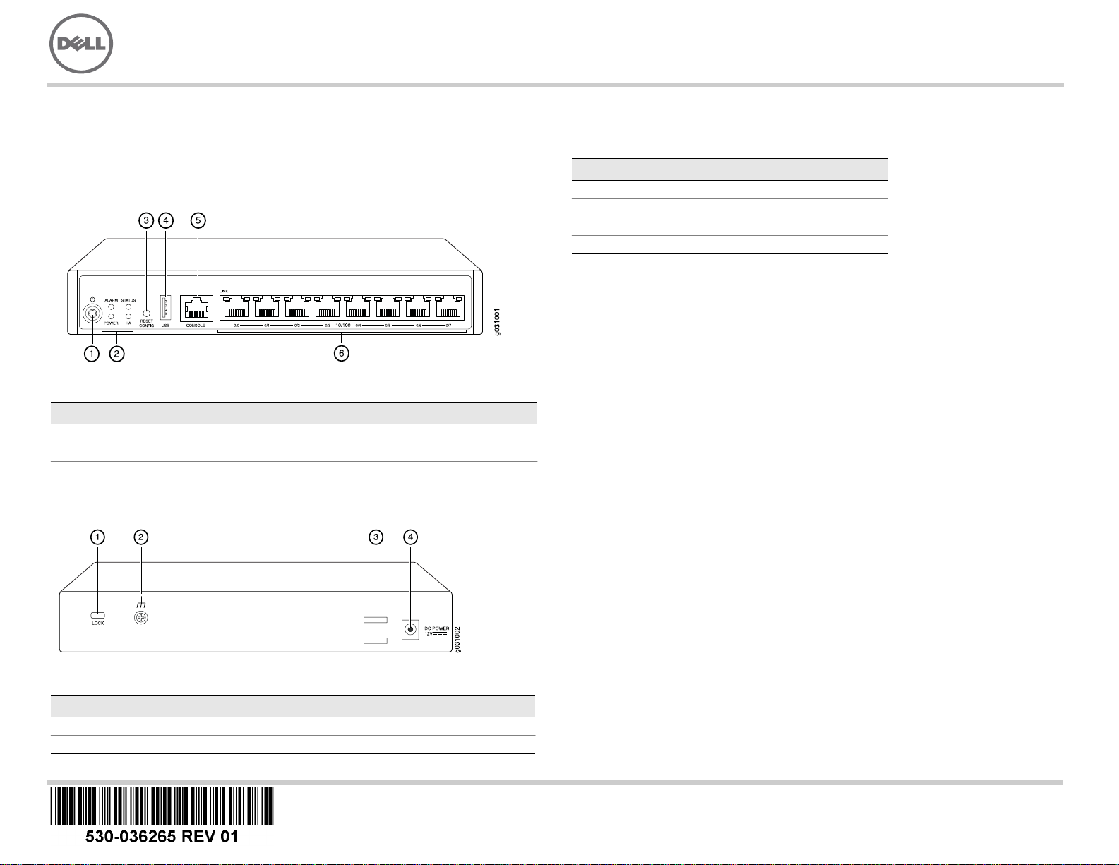
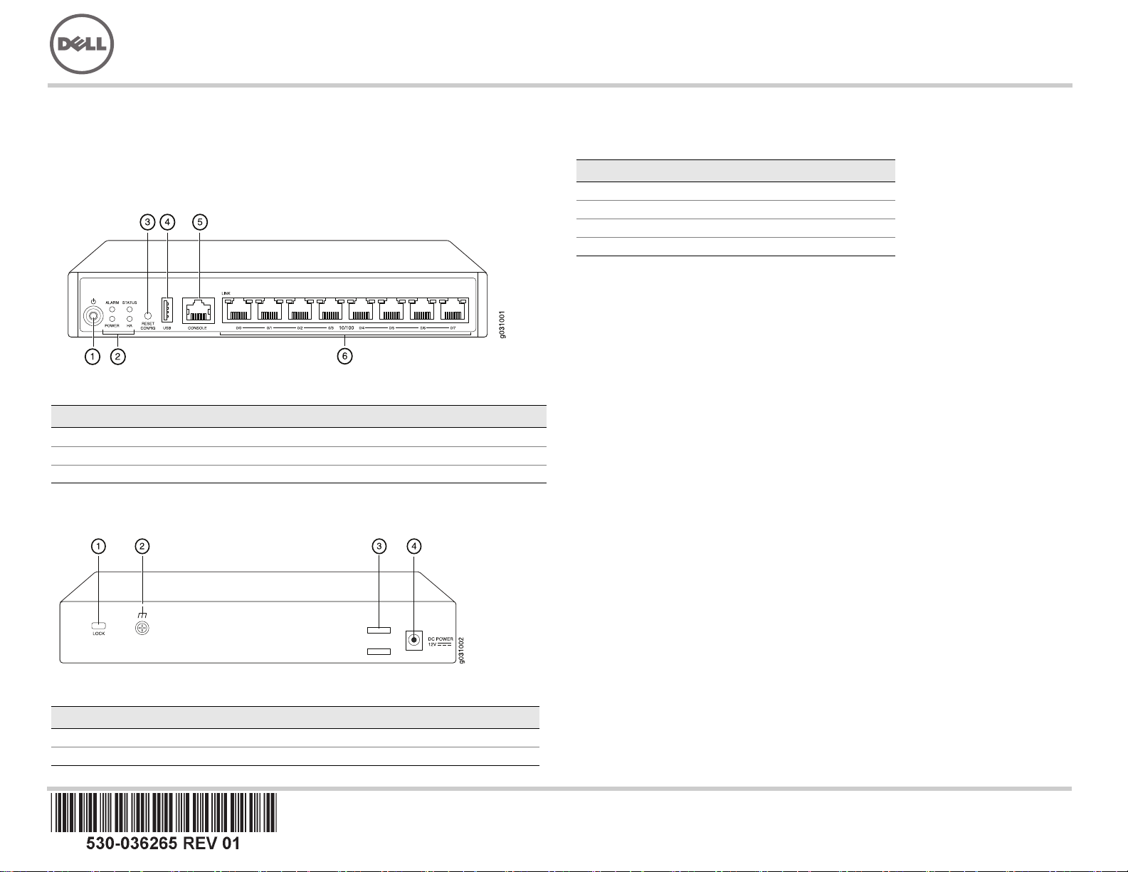
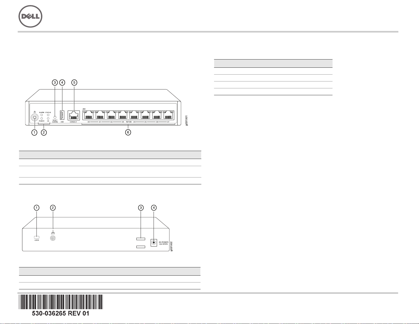
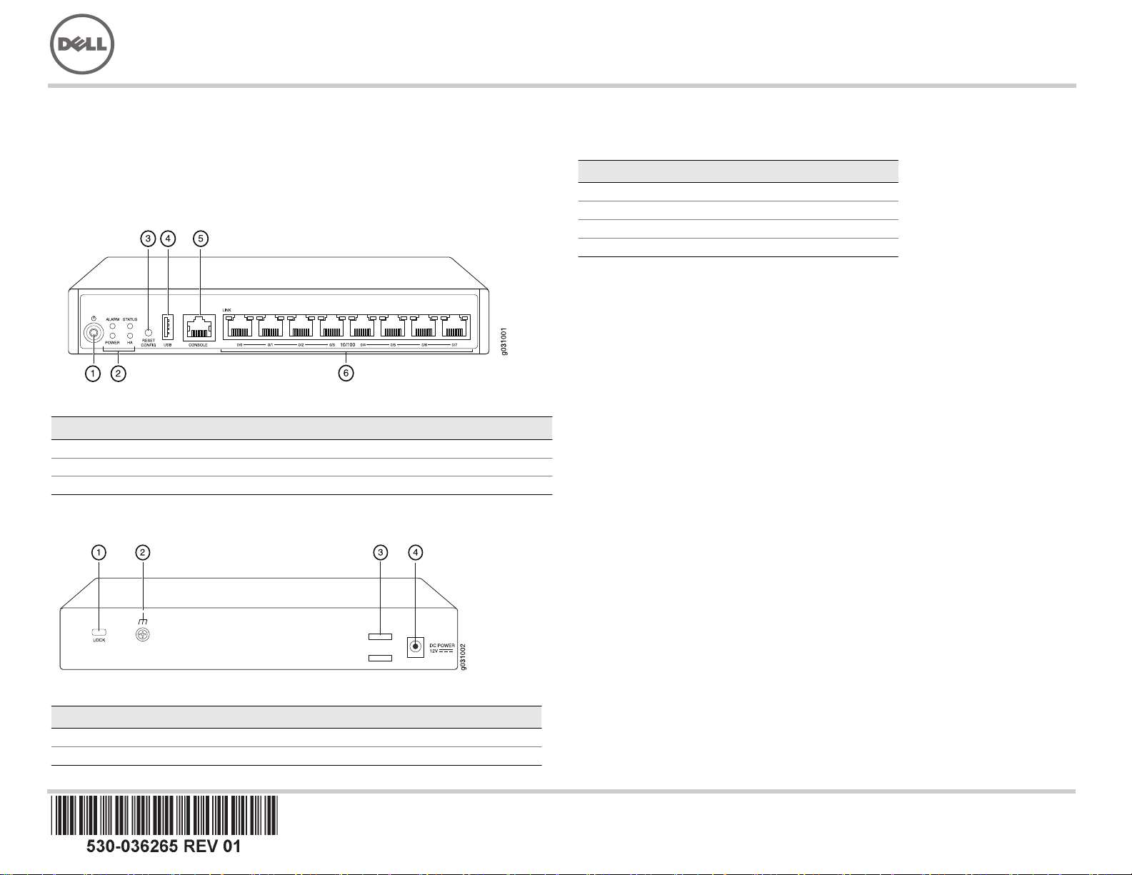
J-SRX100 Services Gateway Front Panel
J-SRX100
Callout Description Callout Description
1 Power button 4 USB port
2 LEDs (ALARM, POWER, STATUS, HA) 5 Console port
3 Reset Config button 6 Fast Ethernet ports
J-SRX100 Services Gateway Back Panel
Callout Description Callout Description
1 Lock for security cable 3 Cable tie holder
2 Grounding point 4 Power supply input
J-SRX100 Services Gateway Models
The following models of J-SRX100 Services Gateway are available:
Device DDR Memory
J-SRX100B 512 MB
J-SRX100H 1 GB
J-SRX100S 1 GB
J-SRX100SU 1 GB
Connecting and Configuring the J-SRX100 Services Gateway
Use the instructions below to connect and set up the J-SRX100 Services Gateway to
protect your network. Refer to the LEDs on the front panel of the device to help you
determine the status of the device.
Part 1: Connect the Services Gateway to Earth Ground
1. Obtain a grounding cable—14 AWG single-strand, 4 A—with a ring-type,
vinyl-insulated TV14-6R lug or equivalent attached by a licensed electrician.
2. Connect the grounding cable to a proper earth ground.
3. Place the grounding cable lug over the grounding point on the middle rear of the
chassis, and secure the lug with one M3 screw.
Part 2: Connect the Power Cable to the Device
Connect the power cable to the device and a power source. We recommend using a
surge protector. Note the following indications:
POWER LED (green): The device is receiving power.
STATUS LED (green): The device is operating normally.
ALARM LED (amber): The device is operating normally, and may glow amber as a
rescue configuration has not been set. This is not a panic condition.
NOTE:
After a rescue configuration has been set, an amber ALARM LED indicates a
minor alarm, and a solid red ALARM LED indicates that a major problem exists on the
services gateway.
NOTE:
You must allow the device between 5 and 7 minutes to boot up after you have
powered it on. Wait until the STATUS LED is solid green before proceeding to the next
part.
Page 2
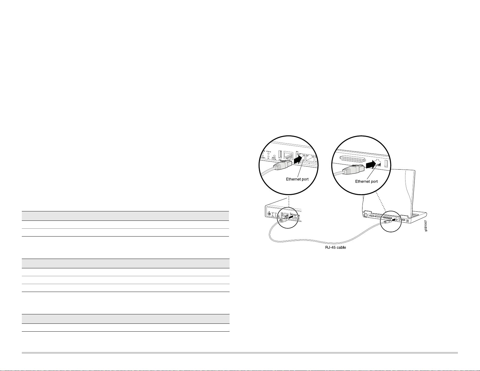
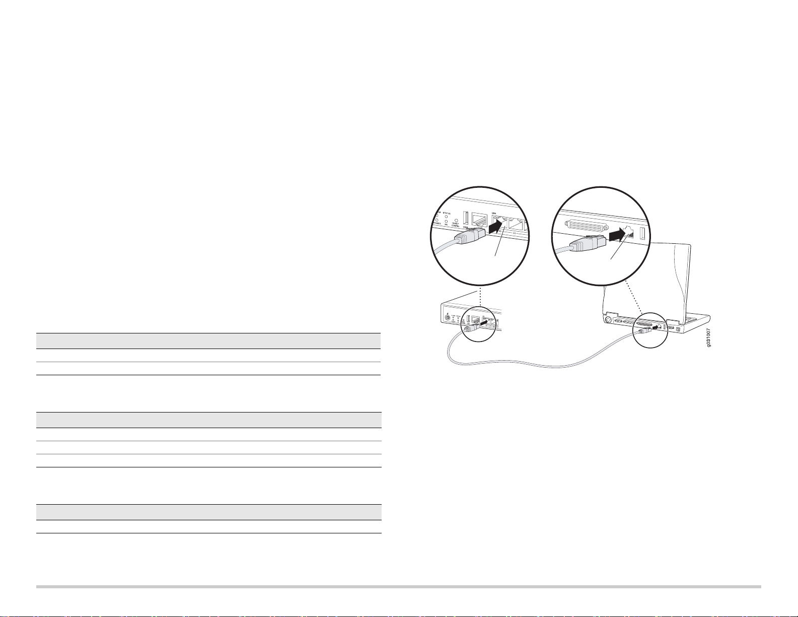
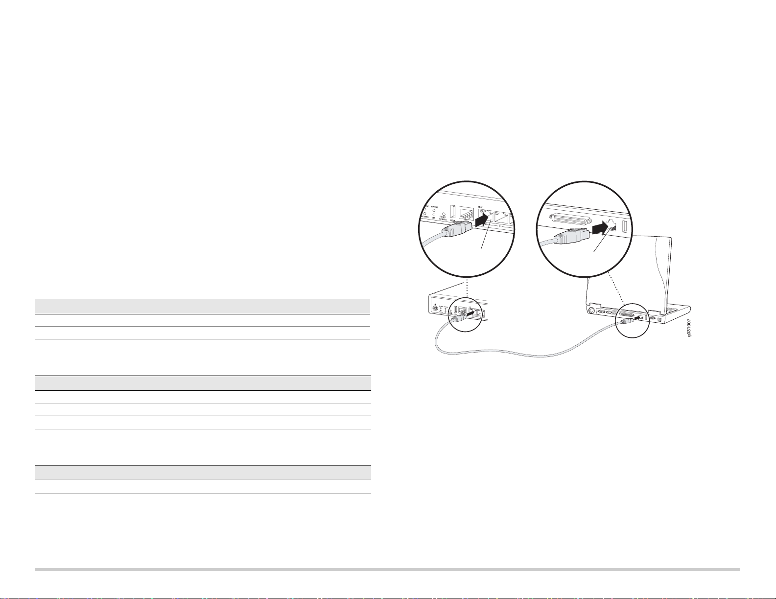
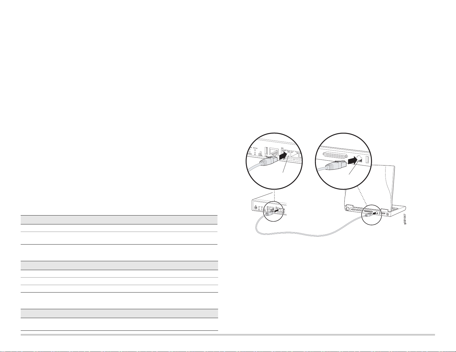
Part 3: Connect the Management Device
Connect the management device to the services gateway using either of the following
methods:
Connect an RJ-45 cable (Ethernet cable) from any one of the fe-0/0/1 through
fe-0/0/7 ports on the front panel to the Ethernet port on the management device
(workstation or laptop) as shown on page 2. We recommend this connection
method. If you are using this method to connect, proceed with Part 4.
Connect an RJ-45 cable (Ethernet cable) from the port labeled CONSOLE to the
supplied DB-9 adapter, which then connects to the serial port on the management
device. (Serial port settings: 9600 8-N-1.)
If you are using this method to connect, proceed with the CLI configuration
instructions available in the Branch SRX Series Services Gateways Golden
Configurations at http://www.juniper.net/us/en/local/pdf/app-notes/3500153-en.pdf.
Part 4: Understanding the Default Configuration Settings
The PowerConnect J-SRX100 Services Gateway is a secure routing device that requires
these basic configuration settings to function properly:
Interfaces must be assigned IP addresses.
Interfaces must be bound to zones.
Policies must be configured between zones to permit/deny traffic.
Source NAT rules must be set.
The device has the following default configuration set when you power it on for the first
time. To be able to use the device, you do not need to perform any initial configuration.
Part 5: Ensure That the Management Device Acquires an IP Address
After connecting the management device to the services gateway, the DHCP server
process on the services gateway will assign an IP address automatically to the
management device. Ensure that the management device acquires an IP address on the
192.168.1/24 subnetwork (other than 192.168.1.1) from the device.
NOTE:
The services gateway functions as a DHCP server and will assign an IP address to
the management device.
If an IP address is not assigned to the management device, manually configure an
IP address in the 192.168.1.0/24 subnetwork. Do not assign the 192.168.1.1 IP
address to the management device, as this IP address is assigned to the device. By
default, the DHCP server is enabled on the L3 VLAN interface, (IRB) vlan.0 (fe-0/0/1
to fe-0/0/7), which is configured with an IP address of 192.168.1.1/24.
When a J-SRX100 Services Gateway is powered on for the first time, it boots using
the factory default configuration.
See the illustration below for details on connecting a management interface:
ACTORY DEFAULT SETTINGS FOR INTERFACES
F
Port Label Interface Security Zone DHCP State IP Address
0/0 fe-0/0/0 untrust client unassigned
0/1 to 0/7 fe-0/0/1 to fe-0/0/7 trust server 192.168.1.1/24
FACTORY DEFAULT SETTINGS FOR SECURITY POLICIES
Source Zone Destination Zone Policy Action
trust untrust permit
trust trust permit
untrust trust deny
FACTORY DEFAULT SETTINGS FOR NAT RULE
Source Zone Destination Zone Policy Action
trust untrust source NAT to untrust zone interface
Part 6: Ensure that an IP Address is Assigned to the Services Gateway
Use one of the following methods to obtain an IP address on the services gateway:
METHOD 1: OBTAINING A DYNAMIC IP ADDRESS ON YOUR SERVICES GATEWAY
Use the fe-0/0/0 port to connect to your Internet Service Provider (ISP). Your ISP will
assign an IP address using the DHCP process.
If you are using this method to obtain an IP address on your services gateway,
proceed with the steps from Part 7 to Part 10 in this document to configure your
device and pass traffic.
Page 2
Page 3
METHOD 2: OBTAINING A STATIC IP ADDRESS ON YOUR SERVICES GATEWAY
Use the fe-0/0/0 port to connect to your ISP. Your ISP will have provided a static IP
address. You will not receive an IP address using the DHCP process.
If you are using this method to obtain an IP address on your services gateway, follow
the instructions from Part 7 to Part 10 in this document.
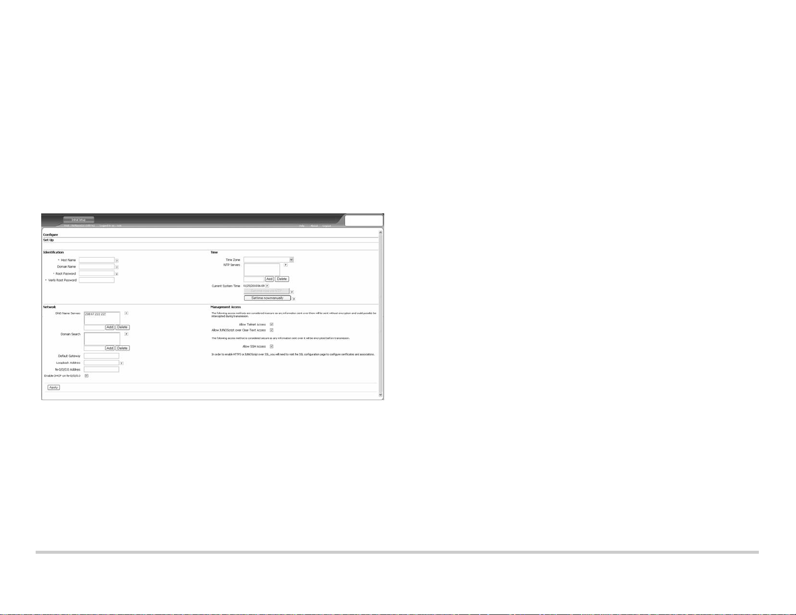
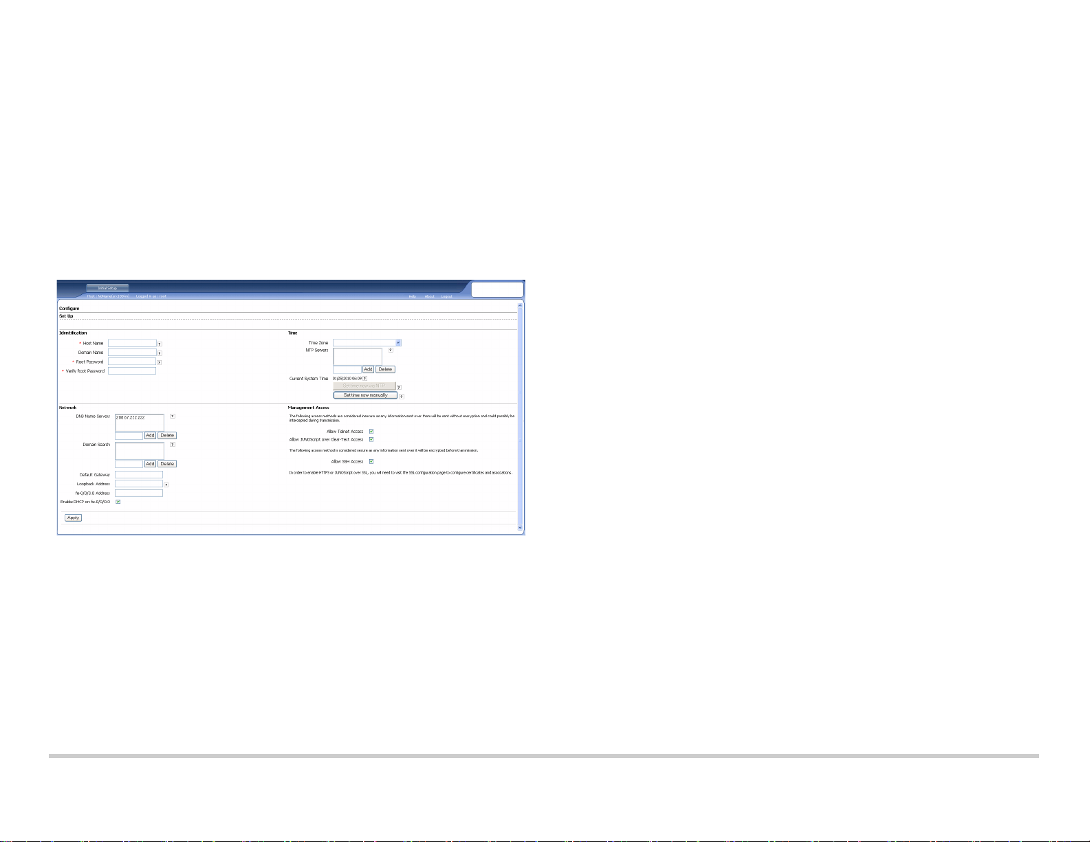
Part 7: Access the J-Web Interface
1. Launch a Web browser on the management device.
2. Enter http://192.168.1.1 in the URL address field. The J-Web login page is
displayed.
3. Specify the default user name as root. Do not enter any value in the Password field.
4. Click Log In. The J-Web Initial Setup page is displayed.
1. Unselect the Enable DHCP on fe-0/0/0.0 check box.
2. Enter the manual IP address provided by your ISP in the fe-0/0/0.0 address field.
The IP address must be entered in the a.b.c.d/xx format, where xx is the subnet
mask.
3. Enter the IP address of the gateway in the Default Gateway field. The IP address for
the gateway is also provided by the ISP.
4. Enter server names in the DNS name servers field. The server names will be
provided by your ISP.
5. Apply the configuration.
Part 9: Apply the Basic Configuration
1. Click Commit to save the basic configuration.
2. Click Apply to apply the basic configuration.
NOTE:
To make any changes to the interface configuration, see the Branch SRX Series
Services Gateways Golden Configurations at
http://www.juniper.net/us/en/local/pdf/app-notes/3500153-en.pdf.
Part 10: Verify the Configuration
Access http://www.support.dell.com to ensure that you are connected to the internet.
This connectivity ensures that you can pass traffic through the services gateway.
NOTE:
If the http://www.support.dell.com page does not load, verify your configuration
settings, and ensure that you have applied the configuration.
After you have completed these steps, you can pass traffic from any trust port to the
untrust port.
Powering Off the Device
To power off the services gateway, you can shut it down in one of the following ways:
Graceful shutdown—Press and immediately release the Power button. The device
begins gracefully shutting down the operating system.
Immediate shutdown—Press the Power button and hold it for 10 seconds. The
device immediately shuts down. Press the Power button again to power on the
device.
NOTE:
Part 8: Configure the Basic Settings
Configure the basic settings, such as Host Name, Domain Name and Root Password for
your services gateway.
IMPORTANT: Ensure that you have configured the IP address and root password before
you apply the configuration.
NOTE:
All fields marked with an asterisk (*) are mandatory.
If you have used Method 2 in Part 6 to obtain an IP address on your services gateway,
ensure that you make the following J-Web modifications:
Information in this document is subject to change without notice. All rights reserved. Reproduction of these materials in any manner whatsoever without the written permission of Juniper Networks is strictly forbidden. Trademarks used
in this text: Dell™, the DELL™ logo, and PowerConnect™ are trademarks of Dell Inc. Juniper Networks® and G33® are registered trademarks of Juniper Networks, Inc. in the United States and other countries. All other trademarks,
service marks, registered trademarks, or registered service marks are the property of their respective owners. Juniper Networks assumes no responsibility for any inaccuracies in this document. Juniper Networks reserves the right to
change, modify, transfer, or otherwise revise this publication without notice. Products made or sold by Juniper Networks or components thereof might be covered by one or more of the following patents that are owned by or licensed to
Juniper Networks: U.S. Patent Nos. 5,473,599, 5,905,725, 5,909,440, 6,192,051, 6,333,650, 6,359,479, 6,406,312, 6,429,706, 6,459,579, 6,493,347, 6,538,518, 6,538,899, 6,552,918, 6,567,902, 6,578,186, and 6,590,785. Copyright ©
2010, Juniper Networks, Inc. All rights reserved. Printed in USA. Part Number: 530-036265 REV 01, July 2010.
You can reboot or halt the system in J-Web by selecting Maintain > Reboot.
For additional configuration information, see the Branch SRX Series Services Gateways
Golden Configurations at
http://www.juniper.net/us/en/local/pdf/app-notes/3500153-en.pdf.
For detailed software configuration information, see the software documentation
available at http://www.juniper.net/techpubs/software/junos-srx/index.html.
Contacting Dell
For technical support, see http://www.support.dell.com.
Page 4
Dell PowerConnect J-Series J-SRX100 服務閘道快速入門
J-SRX
100
使用此快速入門中的說明,協助您將 Dell PowerConnect J-Series J-SRX100 服務閘道連
線至網路。 如需詳細資訊,請參閱 J-SRX100 Services Gateway Hardware Guide,網址
為 http://www.support.dell.com/manuals。
管理型號為
(
J-SRX100
編號 說明 編號 說明
1
2
3
J-SRX100
SRX100)
服務閘道前面板
Power 按鈕
LED (ALARM、POWER、STATUS、HA)
Reset Config 按鈕
服務閘道後面板
4
5
6
USB 連接埠
主控台連接埠
快速乙太網路連接埠
J-SRX100 服務閘道機型
提供以下的 J-SRX100 服務閘道機型:
裝置 DDR 記憶體
J-SRX100B 512 MB
J-SRX100H 1 GB
J-SRX100S 1 GB
J-SRX100SU 1 GB
連接與設定 J-SRX100 服務閘道
使用下列說明來連接及設定 J-SRX100 服務閘道,以保護您的網路。 請參考裝置前面板
上的 LED,以協助您確定裝置的狀態。
第
1
部分: 將服務閘道連接至地面
1. 取得一條接地纜線 (14 AWG 單股,4 A),並由授權的電工將纜線與圓形乙烯基絕緣
TV14-6R 接線片或同型插孔連接。
2. 將接地纜線連接到正確的地面。
3. 將接地纜線接線片置於機箱後方中間的接地點,然後使用一個 M3 螺絲來固定接
線片。
第
2
部分: 將電源纜線連接至裝置
將電源纜線連接至裝置與電源。 我們建議您使用突波保護器。 請注意下列指示:
POWER LED ( 綠色 ): 裝置已通電。
STATUS LED ( 綠色 ): 裝置運作正常。
ALARM LED ( 琥珀黃色 ): 裝置運作正常,此外若未設定救援組態,則可能會亮起琥
珀黃色燈。 這並不屬於緊急情況。
注意:
設定完救援組態後,琥珀黃色 ALARM LED 表示輕微警示,而紅色 ALARM LED 表
示服務閘道存在嚴重問題。
注意:
在開啟裝置電源後,必須讓裝置有 5 到 7 分鐘的啟動時間。 請靜待 STATUS LED
亮起綠燈,然後再繼續下一個部分。
編號 說明 編號 說明
1
2
鎖定安全纜線
接地點
3
4
纜線束固定器
電源供應輸入
Page 5
第
ᄥ✂〝ㅪធၟ
ᄥ✂〝ㅪធၟ
RJ-45 ➤✢
3
部分: 連接管理裝置
使用以下其中一種方法將管理裝置連接至服務閘道:
用 RJ-45 纜線 ( 乙太網路纜線 ) 將前面板上 fe-0/0/1 到 fe-0/0/7 之間的任何一個連接
埠與管理裝置 ( 工作站或筆記型電腦 ) 上的乙太網路連接埠連在一起,如第 2 頁所
示。我們建議您使用這種連接方法。 如果使用此方法進行連接,請繼續第 4 部分。
用 RJ-45 纜線 ( 乙太網路纜線 ) 將標有 CONSOLE 的連接埠與隨附的 DB-9 配接卡相
連,然後將其連接至管理裝置上的序列連接埠。 ( 序列連接埠設定: 9600 8-N-1。)
如果您使用此方法進行連接,請參閱 Branch SRX Series Services Gateways
Golden Configurations ( 網址為
http://www.juniper.net/us/en/local/pdf/app-notes/3500153-en.pdf) 中的 CLI 組態說明
繼續操作。
第
4
部分: 瞭解預設組態設定
PowerConnect J-SRX100 服務閘道是一個安全路由裝置,它需要這些基本組態設定才能
正常運作:
必須為介面指派 IP 位址。
必須將介面連接至區域。
必須在區域間組態政策,以允許 / 拒絕通訊流量。
必須設定來源 NAT 規則。
當您第一次開啟裝置電源時,它會設定下列預設組態。 您不必執行任何初始組態便可使用
裝置。
介面的出廠預設設定
第
5
部分: 確保管理裝置取得
IP
位址
將管理裝置連接至服務閘道後,服務閘道上的 DHCP 伺服器程序會將 IP 位址自動指派給
管理裝置。 確保管理裝置從裝置取得 192.168.1/24 子網路 ( 而不是 192.168.1.1) 上的 IP
位址。
注意:
服務閘道的功能類似於 DHCP 伺服器,而且會為管理裝置指派 IP 位址。
如果未將 IP 位址指派給管理裝置,請手動組態 192.168.1.0/24 子網路中的一個 IP
位址。 請勿將 192.168.1.1 IP 位址指派給管理裝置,因為此 IP 位址已指派給裝置。
依預設,DHCP 伺服器會啟用於 L3 VLAN 介面,亦即 (IRB) vlan.0 (fe-0/0/1 到
fe-0/0/7),其係透過 IP 位址 192.168.1.1/24 組態。
第一次開啟 J-SRX100 服務閘道電源時,其會使用出廠預設組態啟動。
如需連接管理介面的詳細資訊,請參閱下圖:
連接埠標籤 介面 安全區 DHCP 狀態 IP 位址
0/0 fe-0/0/0 untrust
0/1 到 0/7 fe-0/0/1 到 fe-0/0/7
trust
用戶端 未指派
伺服器
192.168.1.1/24
安全性政策的出廠預設設定
來源區 目的區 政策動作
trust untrust
trust trust
untrust trust
NAT
來源區 目的區 政策動作
trust untrust
規則的出廠預設設定
來源 NAT 到 untrust 區域介面
允許
允許
拒絕
第
6
部分: 確認已將
IP
位址指派給服務閘道
使用以下其中一種方法取得服務閘道的 IP 位址:
方法 1: 取得服務閘道的動態
IP
位址
使用 fe-0/0/0 連接埠連線至您的 「網際網路服務供應商」 (ISP)。 您的 ISP 會使用
DHCP 程序指派一個 IP 位址。
如果您使用此方法取得服務閘道的 IP 位址,請繼續執行本文件中第 7 到第 10 部分
的步驟,以設定您的裝置及傳送通訊流量。
第 2 頁
Page 6

方法 2: 取得服務閘道的靜態
使用 fe-0/0/0 連接埠連線至您的 ISP。 您的 ISP 將已提供靜態 IP 位址。 您將不會接
收到使用 DHCP 程序指派的 IP 位址。
如果您使用此方法取得服務閘道的 IP 位址,請遵循本文件中第 7 到第 10 部分的
指示。
第
7
部分: 存取
1. 在管理裝置上啟動 Web 瀏覽器。
2. 在 URL 位址欄位中輸入 http://192.168.1.1。 接著會顯示 J-Web 登入頁面。
3. 將預設使用者名稱指定為 root。 請勿在 Password 欄位中輸入任何值。
4. 按一下 Log In。 接著會顯示 J-Web Initial Setup 頁面。
第
8
部分: 進行基本設定
為服務閘道進行基本設定,例如 Host Name、Domain Name 與 Root Password。
重要: 確認您在套用組態之前,已設定 IP 位址與根密碼。
注意:
標記星號 (*) 的所有欄位皆為必填欄位。
如果您已使用第 6 部分的方法 2 取得服務閘道的 IP 位址,請務必修改下列的 J-Web
內容:
J-Web
介面
IP
位址
1. 取消選擇 Enable DHCP on fe-0/0/0.0 核取方塊。
2. 在 fe-0/0/0.0 位址欄位中輸入 ISP 提供給您的手動 IP 位址。 必須以 a.b.c.d/xx 的格
式輸入此 IP 位址,其中 xx 是子網路遮罩。
3. 在 Default Gateway 欄位中輸入閘道的 IP 位址。 閘道的 IP 位址也由 ISP 提供。
4. 在 DNS name servers 欄位中輸入伺服器名稱。 伺服器名稱由您的 ISP 提供。
5. 套用組態。
第
9
部分: 套用基本組態
1. 按一下 Commit 來儲存基本組態。
2. 按一下 Apply 來套用基本組態。
注意:
若要對介面組態進行任何變更,請參閱 Branch SRX Series Services Gateways
Golden Configurations,網址為
http://www.juniper.net/us/en/local/pdf/app-notes/3500153-en.pdf。
第
10
部分: 驗證組態
存取 http://www.support.dell.com,以確保您已連線至網際網路。 此連線可確保您可以透
過服務閘道傳送通訊流量。
注意:
如果 http://www.support.dell.com 頁面未載入,請驗證組態設定,並確保您已套用
該組態。
完成這些步驟後,您可以將通訊流量從任何信任連接埠傳送至非信任連接埠。
關閉裝置電源
您可以使用以下任何一種方式來關閉服務閘道電源:
平穩關閉 - 按下並立即鬆開電源按鈕。 裝置會開始平穩關閉作業系統。
立即關閉 - 按住電源按鈕 10 秒鐘。 裝置會立即關閉。 再次按下電源按鈕可開啟裝置
電源。
注意:
透過選擇 Maintain > Reboot,您可以在 J-Web 中重新啟動或暫停系統。
如需其他組態資訊,請參閱 Branch SRX Series Services Gateways Golden
Configurations,網址為
http://www.juniper.net/us/en/local/pdf/app-notes/3500153-en.pdf。
如需詳細的軟體組態資訊,請參閱可從
http://www.juniper.net/techpubs/software/junos-srx/index.html 取得的軟體文件。
聯絡 Dell
如需技術支援,請參閱 http://www.support.dell.com。
本文件中的資訊如有變更,恕不另行通知。 保留所有權利。 未經 Juniper Networks 書面許可,嚴格禁止以任何方式複製這些材料。 本文中所使用的商標: Dell™、DELL™ 標誌以及 PowerConnect™ 為 Dell Inc. 的商標。
Juniper Networks® 和 G33® 為 Juniper Networks, Inc. 在美國與其他國家 / 地區的註冊商標。 所有其它商標、服務標記、註冊商標或註冊服務標記都屬於其個別擁有者的財產。 Juniper Networks 對本文件中的任何錯誤,不承擔任何責
任。 Juniper Networks 保留對本出版物進行變更、修改、轉印或其他修訂而不另行通知的權利。 Juniper Networks 製造或銷售的產品或其中的元件可能涵蓋於下列一或多個由 Juniper Networks 所有或 Juniper Networks 已獲授權的專
利: 美國專利號 5,473,599、5,905,725、5,909,440、6,192,051、6,333,650、6,359,479、6,406,312、6,429,706、6,459,579、6,493,347、6,538,518、6,538,899、6,552,918、6,567,902、6,578,186 及 6,590,785。版權所有 ©
2010,Juniper Networks, Inc. 保留所有權利。 美國印刷。 產品編號: 530-036265-ZH-HANT 修訂本 01,2010 年 7 月。
Page 7
Dell PowerConnect J 系列 J-SRX100 服务网关快速入门
J-SRX
100
按照本快速入门中的说明进行操作,即可帮助您将 Dell PowerConnect J 系列 J-SRX100
服务网关连接到网络。 有关详细信息,请参阅 J-SRX100 Services Gateway Hardware
Guide,网址:http://www.support.dell.com/manuals。
(规范型号
J-SRX100
编号 说明 编号 说明
1
2
3
J-SRX100
SRX100
)
服务网关前面板
Power 按钮
LED(ALARM、 POWER、STATUS 和
HA)
Reset Config 按钮
服务网关后面板
4
5
6
USB 端口
控制台端口
快速以太网端口
J-SRX100 服务网关型号
提供以下型号的 J-SRX100 服务网关:
设备 DDR 内存
J-SRX100B 512 MB
J-SRX100H 1 GB
J-SRX100S 1 GB
J-SRX100SU 1 GB
连接和配置 J-SRX100 服务网关
按照下面的说明连接和设置 J-SRX100 服务网关以保护网络。 参照设备前面板上的 LED
来帮助您确定设备的状态。
第
1
部分: 将服务网关接地
1. 获取接地电缆—14 AWG 单线, 4 A—带环状、乙烯绝缘 TV14-6R 接线片或同等电
缆,由授权电工接线。
2. 将接地电缆连接到合适的地面。
3. 将接地电缆接线片放在机箱中后部的接地点,并使用一个 M3 螺钉固定接线片。
第
2
部分: 将电源电缆连接到设备
将电源电缆连接到设备和电源。 我们建议使用电涌保护器。 请注意以下指示 :
POWER LED (绿色): 设备通电。
STATUS LED (绿色): 设备正常工作。
ALARM LED (琥珀黄色): 设备正常工作,但可能由于未设置救援配置而发出琥珀
色黄光。 这并不是紧急情况。
注意:
设置完救援配置后,琥珀黄色的 ALARM LED 表示不严重的警告,而红色常亮的
ALARM LED 表示服务网关存在严重问题。
注意:
接通电源后,必须等待 5 至 7 分钟的设备启动时间。 请等待至 STATUS LED 变为
绿色常亮,再执行下一部分。
编号 说明 编号 说明
1
2
安全电缆锁
接地点
3
4
电缆固定夹
电源输入
Page 8
第
ά⦶保䭻⑯
ά⦶保䭻⑯
3+䗁侒
3
部分: 连接管理设备
使用以下任一方法将管理设备连接到服务网关:
按照第 2 页中的图示,将 RJ-45 电缆(以太网电缆)从前面板上 fe-0/0/1 至 fe-0/0/7
端口中的任何一个连接到管理设备 (工作站或便携式计算机)上的以太网端口。我
们建议使用这种连接方法。 如果您使用此方法进行连接,请继续第 4 部分。
将 RJ-45 电缆 (以太网电缆)从标有 CONSOLE 的端口连接到提供的 DB-9 适配
器,然后将其连接到管理设备上的串行端口。 (串行端口设置: 9600 8-N-1。)
如果使用此方法进行连接,请继续执行 Branch SRX Series Services Gateways Golden
Configurations 中提供的 CLI 配置说明,该文档的网址为
http://www.juniper.net/us/en/local/pdf/app-notes/3500153-en.pdf。
第
4
部分: 了解缺省配置设置
PowerConnect J-SRX100 服务网关是需要进行以下基本配置设置才能正常运行的安全路
由设备:
必须为接口分配 IP 地址。
必须将接口绑定到区段。
必须配置区段间的策略以允许 / 拒绝信息流。
必须设置源 NAT 规则。
首次接通电源时,设备已设置以下缺省配置。 无需进行任何初始配置即可使用设备。
接口的出厂缺省设置
端口标签 接口 安全区段 DHCP 状态 IP 地址
0/0 fe-0/0/0 untrust
0/1 到 0/7 fe-0/0/1 到 fe-0/0/7
trust
客户端 未分配
服务器
192.168.1.1/24
第
5
部分: 确保管理设备获得
IP
地址
将管理设备连接到服务网关后,服务网关上的 DHCP 服务器进程会自动为管理设备分配
一个 IP 地址。 确保管理设备能从该设备获得 192.168.1/24 子网 (而不是 192.168.1.1)
上的 IP 地址。
注意:
服务网关起着 DHCP 服务器的作用,将会给管理设备分配 IP 地址。
如果未给管理设备分配 IP 地址,请手动配置 192.168.1.0/24 子网中的 IP 地址。 不
要给管理设备分配 192.168.1.1 IP 地址,因为此 IP 地址已分配给该设备。 缺省情况
下, DHCP 服务器在 L3 VLAN 接口 (IRB) vlan.0 (fe-0/0/1 至 fe-0/0/7)上处于启用
状态,该接口的 IP 地址配置为 192.168.1.1/24。
首次接通 J-SRX100 服务网关的电源时,它会使用出厂缺省配置启动。
有关连接管理接口的详细信息,请参阅下图:
安全策略的出厂缺省设置
源区段 目的区段 策略动作
trust untrust
trust trust
untrust trust
NAT
规则的出厂缺省设置
源区段 目的区段 策略动作
trust untrust
允许
允许
拒绝
源 NAT 到 untrust 区段接口
第
6
部分: 确保已将
IP
地址分配给服务网关
使用以下方法之一在服务网关上获得 IP 地址:
方法 1: 在服务网关上获得动态
IP
地址
使用 fe-0/0/0 端口连接到互联网服务提供商 (ISP)。 ISP 将使用 DHCP 进程分配一个
IP 地址。
如果您使用此方法获得服务网关的 IP 地址,请继续本文档第 7 部分至第 10 部分中
的步骤来配置设备和传送信息流。
第 2 页
Page 9
方法 2: 在服务网关上获得静态
使用 fe-0/0/0 端口连接到 ISP。 ISP 将提供一个静态 IP 地址。 使用 DHCP 进程不会
收到 IP 地址。
如果您使用此方法获得服务网关的 IP 地址,请按照本文档第 7 部分至第 10 部分中
的说明进行操作。
第
7
部分: 访问
1. 在管理设备上启动 Web 浏览器。
2. 在 URL 地址字段中输入 http://192.168.1.1。 将显示 J-Web 登录页面。
3. 指定缺省用户名为 root。 不要在 Password 字段中输入任何值。
4. 单击 Log In。 将显示 J-Web Initial Setup 页面。
J-Web
界面
IP
地址
1. 取消选中 Enable DHCP on fe-0/0/0.0 复选框。
2. 在 fe-0/0/0.0 地址字段中输入 ISP 提供的手动 IP 地址。 必须以 a.b.c.d/xx 的格式输
入 IP 地址,其中 xx 为子网掩码。
3. 在 Default Gateway 字段中输入网关的 IP 地址。 网关的 IP 地址同样由 ISP 提供。
4. 在 DNS name servers 字段中输入服务器名称。 服务器名称将由 ISP 提供。
5. 应用配置。
第
9
部分: 应用基本配置
1. 单击 Commit 保存基本配置。
2. 单击 Apply 应用基本配置。
注意:
要对接口配置进行任何更改,请参阅 Branch SRX Series Services Gateways
Golden Configurations,网址为
http://www.juniper.net/us/en/local/pdf/app-notes/3500153-en.pdf。
第
10
部分: 验证配置
访问 http://www.support.dell.com 以确保您已连接到 Internet。 该连通性确保您可通过服
务网关传送信息流。
注意:
如果 http://www.support.dell.com 页面未加载,请检查配置设置并确保已应用配
置。
完成这些步骤后,可以将信息流从任何 trust 端口传送到 untrust 端口。
切断设备电源
要切断服务网关电源,可通过以下方式之一将其关闭 :
平滑关闭 - 按下并立即松开电源按钮。 设备开始从容地关闭操作系统。
立即关闭 - 按下电源按钮并保持 10 秒钟。 设备立即关闭。 再次按下该按钮可接通设
备电源。
注意:
您可在 J-Web 界面中通过选择 Maintain > Reboot 来重新启动或停止系统。
有关其他配置信息,请参阅 Branch SRX Series Services Gateways Golden
Configurations,网址为
http://www.juniper.net/us/en/local/pdf/app-notes/3500153-en.pdf。
第
8
部分: 配置基本设置
配置服务网关的基本设置,如 Host Name、 Domain Name 和 Root Password。
重要: 确保在应用配置之前已配置了 IP 地址和根密码。
注意:
所有标有星号 (*) 的字段均为必填字段。
如果您已使用第 6 部分中的方法 2 获取服务网关的 IP 地址,请确保进行以下 J-Web
修改:
本文档中的信息如有更改,恕不另行通知。 保留所有权利。 未经 Juniper Networks 书面许可,严禁以任何方式复制这些材料。 本文中使用的商标: D ell™、 DELL™ 徽标和 PowerConnect™ 是 Dell Inc. 的商标。 Juniper Networks® 和
G33® 是 Juniper Networks, Inc. 在美国及其它国家 / 地区的注册商标。 所有其它 商标、服务标志、注册商标或注册服务标志均属其各自所有者的资产。 Juniper Networks 对本文档中的任何错误不承担任何责任。 Juniper Networks 保留变
更、修改、转印或另外修订本出版物而不另行通知的权利。 Juniper Networks 制造或销售的产品或者 相关组件可能受到以下 Juniper Networks 拥有或得到授权的一项或多项专利的保护: 美国专利编号 5,473,599、 5,905,725、
5,909,440、 6,192,051、6,333,650、6,359,479、 6,406,312、6,429,706、 6,459,579、6,493,347、6,538,518、 6,538,899、6,552,918、 6,567,902、 6,578,186 和 6,590,785。版权所有 © 2010, Juniper Networks, Inc. 保留所有权利。
美国印刷。 部件号: 530-036265-ZH-HANS 版本 01, 2010 年 7 月。
有关软件配置的详细信息,请参阅
http://www.juniper.net/techpubs/software/junos-srx/index.html 上提供的软件文档。
联系 Dell
要获取技术支持,请访问 http://www.support.dell.com。
Page 10
Passerelle de services Dell PowerConnect J-Series
J-SRX
100
J-SRX100 - Guide de mise en route
Suivez les instructions du présent guide de mise en route pour connecter la passerelle
de services Dell PowerConnect J-Series J-SRX100 à votre réseau. Pour plus
d’informations, consultez le manuel J-SRX100 Services Gateway Hardware Guide
disponible sur le site Internet http://www.support.dell.com/manuals.
(Numéro de modèle réglementaire SRX100)
Panneau avant de la passerelle de services J-SRX100
Référence Description Référence Description
1 Bouton Power 4 Port USB
2 DEL (ALARM, POWER, STATUS et HA) 5 Port CONSOLE
3 Bouton Reset Config 6 Ports Fast Ethernet
Panneau arrière de la passerelle de services J-SRX100
Référence Description Référence Description
1 Verrou du câble de sécurité 3 Support de câble
2 Point de mise à la terre 4 Connecteur d’alimentation
Modèles de passerelle de services J-SRX100
Les modèles de passerelle de services J-SRX100 suivants sont disponibles :
Unité Mémoire DDR
J-SRX100B 512 Mo
J-SRX100H 1 Go
J-SRX100S 1 Go
J-SRX100SU 1 Go
Connexion et configuration de la passerelle de services J-SRX100
Suivez les instructions ci-après pour connecter et configurer la passerelle de services
J-SRX100 à votre réseau afin de le protéger. Observez les DEL sur le panneau avant de
l’unité pour mieux déterminer l’état de cette dernière.
Partie 1 : Raccord de la passerelle de services à la terre
1. Procurez-vous un câble de mise à la terre — 14 AWG monotoron, 4 A — avec œillet
TV14-6R de type anneau à gaine en vinyle ou équivalent fixé par un électricien
professionnel.
2. Connectez le câble de mise à la terre à une terre correcte.
3. Placez l’œillet du câble de mise à la terre sur le point de mise à la terre dans la
partie centrale arrière du châssis, puis fixez l’œillet avec une vis M3.
Partie 2 : Raccord du câble d’alimentation à l’unité
Reliez l’unité au secteur à l’aide du câble d’alimentation. L’utilisation d’un dispositif de
protection contre les surtensions est recommandée. Notez les points suivants :
POWER LED (verte) : l’unité est sous tension.
STATUS LED (verte) : l’unité fonctionne normalement.
ALARM LED (orange) : l’unité fonctionne normalement, mais aucune configuration
de sauvegarde n’a été définie. Il ne s’agit pas d’un cas d’alerte.
REMARQUE :
la ALARM LED indique une alarme mineure et une lumière rouge fixe indique la
détection d’un problème majeur sur la passerelle de services.
REMARQUE :
prendre de5à7minutes. Veuillez patienter jusqu’à ce que laSTATUS LED s’allume en
vert avant de passer à l’étape suivante.
si une configuration de sauvegarde est définie, une lumière orange de
lorsque vous mettez l’unité sous tension, sa procédure d’amorçage peut
Page 11
Partie 3 : Connexion du dispositif de gestion
Port Ethernet
Port Ethernet
Câble RJ-45
Connectez le dispositif de gestion à la passerelle de services de l’une des manières
suivantes :
À l’aide d’un câble RJ-45 (câble Ethernet), raccordez l’un des ports fe-0/0/1
à fe-0/0/7 du panneau avant de l’unité au port Ethernet du dispositif de gestion
(poste de travail ou ordinateur portable), comme indiqué à la page 2 (méthode
recommandée). Si vous optez pour cette méthode de connexion, passez à la
Partie 4.
À l’aide d’un câble RJ-45 (câble Ethernet), reliez le port CONSOLE de l’unité à
l’adaptateur DB-9 fourni, puis connectez ce dernier au port série du dispositif de
gestion. (Paramètres du port série : 9600 8-N-1.)
Si vous optez pour cette méthode de connexion, reportez-vous aux instructions de
configuration de l’interface de ligne de commande indiquées dans le guide Branch
SRX Series Services Gateways Golden Configurations disponible à l’adresse
http://www.juniper.net/us/en/local/pdf/app-notes/3500153-en.pdf.
Partie 4 : Présentation des paramètres de configuration par défaut
La passerelle de services PowerConnect J-SRX100 est un dispositif de routage sécurisé
dont le bon fonctionnement est tributaire des paramètres de configuration de base
suivants :
Vous devez attribuer des adresses IP aux interfaces.
Vous devez associer les interfaces à des zones.
Vous devez configurer des règles autorisant ou refusant la transmission de données
entre les zones.
Vous devez définir les règles NAT des adresses source.
Lorsque vous mettez l’unité sous tension pour la première fois, elle utilise la configuration
par défaut suivante. Pour vous en servir, aucune configuration initiale n’est nécessaire.
Partie 5 : Vérification de l’attribution d’une adresse IP au dispositif de gestion
Une fois le dispositif de gestion connecté à la passerelle de services, le processus du
serveur DHCP sur cette passerelle attribue automatiquement une adresse IP à ce
dispositif. Assurez-vous que le dispositif de gestion reçoit bien de l’unité une adresse IP
sur le sous-réseau 192.168.1/24 (autre que 192.168.1.1).
REMARQUE :
La passerelle de services se comporte comme un serveur DHCP et attribue une
adresse IP au dispositif de gestion.
Si aucune adresse IP n’est attribuée au dispositif de gestion, configurez-en une
manuellement sur le sous-réseau 192.168.1.0/24. N’attribuez pas l’adresse IP
192.168.1.1 au dispositif de gestion ; elle est déjà attribuée à l’unité. Par défaut, le
serveur DHCP est activé sur l’interface de VLAN de couche 3, à savoir (IRB) vlan.0
(de fe-0/0/1 à fe-0/0/7), dotée de l’adresse IP 192.168.1.1/24.
Lorsque vous mettez la passerelle de services J-SRX100 sous tension pour la
première fois, elle démarre en utilisant sa configuration par défaut définie en usine.
Pour plus d’informations sur la connexion d’une interface de gestion, observez
l’illustration ci-après :
P
ARAMèTRES PAR DéFAUT DéFINIS EN USINE DES INTERFACES
Port Label Interface Security Zone DHCP State IP Address
0/0 fe-0/0/0 untrust client non attribuée
de 0/1 à 0/7 de fe-0/0/1
à fe-0/0/7
trust server 192.168.1.1/24
PARAMèTRES PAR DéFAUT DéFINIS EN USINE DES RèGLES DE SéCURITé
Source Zone Destination Zone Policy Action
trust untrust autoriser
trust trust autoriser
untrust trust interdire
ARAMèTRES PAR DéFAUT DéFINIS EN USINE DE LA RèGLE NAT
P
Source Zone Destination Zone Policy Action
trust untrust définir l’adresse NAT source sur
l’interface de la zone Untrust
Partie 6 : Vérification de l’attribution d’une adresse IP à la passerelle de
services
Pour obtenir une adresse IP sur la passerelle de services, procédez de l’une des
manières suivantes :
Mé
THODE 1: OBTENTION D’UNE ADRESSE IP DYNAMIQUE SUR LA PASSERELLE DE
SERVICES
Connectez-vous à votre fournisseur d’accès Internet (FAI) via le port fe-0/0/0.
Votre FAI va utiliser le processus DHCP pour attribuer une adresse IP à l’unité.
Si vous optez pour cette méthode d’obtention de l’adresse IP sur la passerelle,
passez aux instructions des Parties 7 à 10 du présent document pour configurer
l’unité et la transmission de données.
Page 2
Page 12

MéTHODE 2: OBTENTION D’UNE ADRESSE IP STATIQUE SUR LA PASSERELLE DE
SERVICES
Connectez-vous à votre FAI via le port fe-0/0/0. Votre FAI vous communique une
adresse IP statique. Il n’utilisera pas le processus DHCP pour vous attribuer une
adresse IP.
Si vous optez pour cette méthode d’obtention de l’adresse IP sur la passerelle,
passez aux instructions des Parties 7 à 10 du présent document.
Partie 7 : Accès à l’interface J-Web
1. Lancez un navigateur Web sur le dispositif de gestion.
2. Saisissez http://192.168.1.1 dans le champ d’adresse URL. La page de connexion
à l’interface J-Web s’affiche.
3. Indiquez le nom d’utilisateur par défaut root. N’entrez aucun mot de passe dans le
champ Password.
4. Cliquez sur Log In. La page J-Web Initial Setup apparaît.
1. Décochez la case Enable DHCP on fe-0/0/0.0.
2. Saisissez l’adresse IP manuelle fournie par votre FAI dans le champ
d’adresse fe-0/0/0.0. Cette adresse IP doit respecter le format a.b.c.d/xx, xx étant
le masque de sous-réseau.
3. Saisissez l’adresse IP de la passerelle dans le champ Default Gateway. Vous
obtiendrez également cette adresse IP auprès de votre FAI.
4. Saisissez le nom des serveurs dans le champ DNS name servers. Vous obtiendrez
le nom de ces serveurs auprès de votre FAI.
5. Appliquez la configuration.
Partie 9 : Application de la configuration de base
1. Cliquez sur Commit pour enregistrer la configuration de base.
2. Cliquez sur Apply pour appliquer la configuration de base.
REMARQUE :
pour modifier la configuration de l’interface, consultez le manuel Branch
SRX Series Services Gateways Golden Configurations disponible à l’adresse
http://www.juniper.net/us/en/local/pdf/app-notes/3500153-en.pdf.
Partie 10 : Vérification de la configuration
Accédez au site http://www.support.dell.com pour vérifier votre connexion Internet. Si la
connexion s’établit, vous avez la confirmation que vous pouvez transmettre des données
via la passerelle de services.
REMARQUE :
paramètres de configuration et vérifiez que vous avez appliqué la configuration.
Ces vérifications terminées, vous pouvez transmettre des données depuis n’importe quel
port trust vers le port untrust.
si la page http://www.support.dell.com ne se charge pas, examinez vos
Mise hors tension de l’unité
Pour arrêter la passerelle de services, procédez de l’une des manières suivantes :
Arrêt normal : appuyez sur le bouton Power puis relâchez-le immédiatement. L’unité
commence à arrêter normalement le système d’exploitation.
Arrêt immédiat : maintenez le bouton Power enfoncé pendant 10 secondes. L’unité
s’arrête immédiatement. Appuyez une nouvelle fois sur le bouton Power pour
rallumer l’unité.
REMARQUE :
Maintain > Reboot.
Partie 8 : Configuration des paramètres de base
Configurez les paramètres de base, tels que Host Name, Domain Name et Root
Password, de la passerelle de services.
IMPORTANT : avant d’appliquer votre configuration, vérifiez que vous avez configuré
l’adresse IP et le mot de passe de l’utilisateur root.
REMARQUE :
Si, à la Partie 6, vous avez opté pour la Méthode 2 pour obtenir une adresse IP sur la
passerelle de services, n’oubliez pas de modifier les paramètres J-Web comme suit :
Les informations présentées dans ce document sont susceptibles d’être modifiées sans avis préalable. Tous droits réservés. Toute reproduction de ces matériaux, quelle que soit la méthode utilisée, est formellement interdite sans l’accord
écrit préalable de Juniper Networks. Dans le présent texte, Dell™, le logo DELL™ et PowerConnect™ sont des marques commerciales de Dell Inc. Juniper Networks® et G33® sont des marques déposées de Juniper Networks, Inc. aux
États-Unis et dans d’autres pays. Toutes les autres marques commerciales, marques de service, marques déposées ou marques de service déposées sont la propriété de leurs détenteurs respectifs. Juniper Networks décline toute
responsabilité quant à la présence éventuelle d’imprécisions dans ce document. Juniper Networks se réserve le droit de modifier, transférer ou réviser de toute autre manière cette publication sans préavis. Les produits fabriqués ou vendus
par Juniper Networks ou les composants de ces produits peuvent être protégés par l’un ou plusieurs des brevets suivants qui appartiennent à Juniper Networks ou font l’objet d’une licence Juniper Networks : n° de brevets aux États-Unis :
5,473,599, 5,905,725, 5,909,440, 6,192,051, 6,333,650, 6,359,479, 6,406,312, 6,429,706, 6,459,579, 6,493,347, 6,538,518, 6,538,899, 6,552,918, 6,567,902, 6,578,186 et 6,590,785. Copyright © 2010, Juniper Networks, Inc. Tous droits
réservés. Imprimé aux États-Unis. Référence : 530-036265-FR RÉV. 01 juillet 2010.
chaque champ signalé par un astérisque (*) est obligatoire.
Pour obtenir des informations complémentaires sur la configuration, consultez le manuel
Branch SRX Series Services Gateways Golden Configurations disponible à l’adresse
http://www.juniper.net/us/en/local/pdf/app-notes/3500153-en.pdf.
Pour plus d’informations sur la configuration logicielle, consultez la documentation
correspondante disponible à l’adresse
http://www.juniper.net/techpubs/software/junos-srx/index.html.
Contacter Dell
Pour obtenir une assistance technique, consultez le site Web
http://www.support.dell.com.
pour redémarrer ou arrêter le système dans l’interface J-Web, sélectionnez
Page 13

Dell PowerConnect J-Serie J-SRX100 Services Gateway –
J-SRX
100
Schnellstart
Lesen Sie die Anweisungen in dieser Schnellstartanleitung, um das Dell PowerConnect
J-Serie J-SRX100-Services-Gateway mit Ihrem Netzwerk zu verbinden. Details finden
Sie im -SRX100 Services Gateway Hardware Guide unter
http://www.support.dell.com/manuals.
(Modellnummer SRX100)
J-SRX100-Services-Gateway – Vorderseite
Nr. Beschreibung Nr. Beschreibung
1 Power-Taste 4 USB-Port
2 LEDs (ALARM, POWER, STATUS, HA) 5 Konsolenport
3 Reset Config-Schalter 6 Fast Ethernet-Ports
J-SRX100-Services-Gateway – Rückseite
Beschriftung Beschreibung Beschriftung Beschreibung
1 Sperre für Sicherheitskabel 3 Kabelhalterung
2 Erdungspunkt 4 Eingang für Netzteil
J-SRX100-Services-Gateway – Modelle
Die folgenden zwei Modelle von J-SRX100-Services-Gateways sind verfügbar:
Gerät DDR-Speicher
J-SRX100B 512 MB
J-SRX100H 1 GB
J-SRX100S 1 GB
J-SRX100SU 1 GB
Anschließen und Konfigurieren des J-SRX100-Services-Gateways
Schützen Sie Ihr Netzwerk, indem Sie das J-SRX100-Services-Gateway gemäß
folgenden Anweisungen anschließen und einrichten. Den Status des Geräts erkennen
Sie am Leuchten der jeweiligen LED an der Vorderseite des Geräts.
Teil 1: Verbinden des Services Gateway mit der Erdung
1. Besorgen Sie ein Erdungskabel – 14 AWG, einadrig, 4 A mit TV14-6R-Kabelschuh
und Vinyl- oder gleichwertiger Isolierung, das von einem Elektriker installiert wird.
2. Schließen Sie das Erdungskabel an einen geeigneten Erdungsanschluss an.
3. Legen Sie den Kabelschuh des Erdungskabels über den Erdungspunkt in der Mitte
der Rückseite des Chassis, und befestigen Sie ihn mit einer M3-Schraube.
Teil 2: Anschließen des Netzkabels am Gerät
Verbinden Sie das Gerät mittels Netzkabel mit einer Stromquelle. Wir empfehlen die
Verwendung eines Überspannungsschutzes. Beachten Sie die folgenden Hinweise:
POWER-LED (grün): Das Gerät ist am Stromnetz angeschlossen.
STATUS-LED (grün): Normaler Betrieb des Geräts.
ALARM-LED (gelb): Der Betrieb des Geräts verläuft ordnungsgemäß, wobei jedoch
unter Umständen ein gelbes Warnlicht aufleuchtet, wenn keine Notfallkonfiguration
eingerichtet wurde. Dabei handelt es sich nicht um einen gefährlichen Zustand.
HINWEIS:
auf einen kleineren Alarm hin, wohingegen eine rote ALARM-LED auf ein schwerwiegendes Problem im Services-Gateway hindeutet.
HINWEIS:
für den Startvorgang. Warten Sie, bis die STATUS-LED grün leuchtet, bevor Sie
fortfahren.
Nach dem Einrichten einer Notfallkonfiguration weist eine gelbe ALARM-LED
Das Gerät benötigt nach dem Einschalten zwischen fünf und sieben Minuten
Page 14

Teil 3: Anschließen des Verwaltungsgeräts
Ethernet-Port
Ethernet-Port
RJ-45-Kabel
Verbinden Sie das Verwaltungsgerät mit einer der folgenden Methoden mit dem
Services-Gateway:
Verbinden Sie ein RJ-45-Kabel (Ethernet-Kabel) von einem der Ports (fe-0/0/1 bis
fe-0/0/7) an der Vorderseite mit dem Ethernet-Port des Verwaltungsgeräts (Workstation
oder Laptop) (siehe Seite 2). Diese Verbindungsmethode wird empfohlen. Wenn Sie
das Gerät auf diese Weise verbinden, fahren Sie mit Teil 4 fort.
Verbinden Sie den Konsolenport mittels eines RJ-45-Kabels Ethernet-Kabel mit dem
mitgelieferten DB-9-Adapter, der wiederum mit dem seriellen Port des
Verwaltungsgeräts verbunden werden muss. (Einstellungen serieller Port: 9600 8-N-1.)
Wenn Sie das Gerät auf diese Weise verbinden, lesen Sie die
CLI-Konfigurationsanweisungen in Branch SRX Series Services Gateways Golden
Configurations unter
http://www.juniper.net/us/en/local/pdf/app-notes/3500153-en.pdf.
Teil 4: Hinweise zu den standardmäßigen Konfigurationseinstellungen
Das PowerConnect J-SRX100-Services-Gateway ist ein Gerät für sicheres Routing, für
dessen ordnungsgemäße Funktion die folgenden Konfigurationseinstellungen
erforderlich sind:
Schnittstellen müssen IP-Adressen zugewiesen werden.
Schnittstellen müssen an Zonen gebunden werden.
Zwischen Zonen müssen Richtlinien konfiguriert werden, um Datenverkehr
zuzulassen bzw. zu verweigern.
Regeln für Quell-NAT müssen festgelegt werden.
Für das Gerät wird beim ersten Einschalten die folgende Standardkonfiguration
festgelegt. Damit Sie das Gerät verwenden können, muss keine Erstkonfiguration
ausgeführt werden.
Teil 5: Sicherstellen der Zuweisung einer IP-Adresse für das
Verwaltungsgerät
Nach dem Anschließen des Verwaltungsgeräts am Services-Gateway weist der
DHCP-Serverprozess für das Services-Gateway dem Verwaltungsgerät automatisch
eine IP-Adresse zu. Stellen Sie sicher, dass das Verwaltungsgerät im Subnetzwerk
192.168.1/24 vom Gerät eine IP-Adresse anfordert (nicht 192.168.1.1).
HINWEIS:
Das Services-Gateway fungiert als DHCP-Server und weist dem Verwaltungsgerät
eine IP-Adresse zu.
Wird dem Verwaltungsgerät keine IP-Adresse zugewiesen, konfigurieren Sie die
IP-Adresse im Subnetzwerk 192.168.1.0/24 manuell. Weisen Sie dem
Verwaltungsgerät nicht die IP-Adresse 192.168.1.1 zu, da diese IP-Adresse dem
Gerät zugewiesen ist. Standardmäßig wird der DHCP-Server auf der
L3-VLAN-Schnittstelle aktiviert, (IRB) vlan.0 (fe-0/0/1 bis fe-0/0/7), die mit der
IP-Adresse 192.168.1.1/24 konfiguriert ist.
Beim ersten Einschalten eines J-SRX100-Services-Gateways wird es mit der
werkseitigen Standardkonfiguration gestartet.
Die folgende Abbildung veranschaulicht die einzelnen Schritte für den Anschluss an eine
Verwaltungsschnittstelle:
W
ERKSEITIGE STANDARDEINSTELLUNGEN FüR SCHNITTSTELLEN
Portbeschriftung Schnittstelle Sicherheitszone DHCP-Status IP-Adresse
0/0 fe-0/0/0 untrust Client nicht zugewiesen
0/1 bis 0/7 fe-0/0/1 bis fe-0/0/7 trust Server 192.168.1.1/24
WERKSEITIGE STANDARDEINSTELLUNGEN FüR SICHERHEITSRICHTLINIEN
Quellzone Zielzone Richtlinienaktion
trust untrust zulassen
trust trust zulassen
untrust trust verweigern
WERKSEITIGE STANDARDEINSTELLUNGEN FüR NAT-REGEL
Quellzone Zielzone Richtlinienaktion
trust untrust Quell-NAT zu Schnittstelle mit
untrusten Zonen
Teil 6: Sicherstellen, dass dem Services-Gateway eine IP-Adresse
zugewiesen wird
Verwenden Sie eine der folgenden Methoden, um für das Services-Gateway eine
IP-Adresse abzurufen:
M
ETHODE 1: ABRUFEN EINER DYNAMISCHEN IP-ADRESSE FüR DAS SERVICES-GATEWAY
Verwenden Sie den Port fe-0/0/0, um eine Verbindung mit dem
Internetdienstanbieter (ISP) herzustellen. Der Internetdienstanbieter weist mit dem
DHCP-Prozess eine IP-Adresse zu.
Rufen Sie mit dieser Methode eine IP-Adresse für das Services-Gateway ab, führen
Sie die Schritte in den Teilen 7 bis 10 dieses Dokuments aus, um das Gerät zu
konfigurieren und den Datenverkehr weiterzuleiten.
Seite 2
Page 15

METHODE 2: ABRUFEN EINER STATISCHEN IP-ADRESSE FüR DAS SERVICES-GATEWAY
Verwenden Sie den Port fe-0/0/0, um eine Verbindung mit dem
Internetdienstanbieter herzustellen. Sie erhalten vom Internetdienstanbieter eine
statische IP-Adresse. Im Rahmen des DHCP-Prozesses erhalten Sie keine
IP-Adresse.
Wenn Sie auf diese Art und Weise eine IP-Adresse für das Services-Gateway
abrufen, befolgen Sie die Anweisungen in den Teilen 7 bis 10 dieses Dokuments.
1. Deaktivieren Sie das Kontrollkästchen Enable DHCP on fe-0/0/0.0.
2. Geben Sie die manuelle IP-Adresse, die Sie vom Internetdienstanbieter erhalten
haben, in das Adressfeld fe-0/0/0.0 ein. Die IP-Adresse muss im Format a.b.c.d/xx
eingegeben werden, wobei xx die Subnetzmaske ist.
3. Geben Sie die IP-Adresse des Gateways im Feld für das Standardgateway ein. Die
IP-Adresse für das Gateway wird ebenfalls vom Internetdienstanbieter bereitgestellt.
4. Geben Sie im Feld DNS name servers Servernamen ein. Die Servernamen werden
vom Internetdienstanbieter bereitgestellt.
5. Übernehmen Sie die Konfiguration.
Teil 7: Zugriff auf die J-Web-Schnittstelle
1. Starten Sie auf dem Verwaltungsgerät einen Webbrowser.
2. Geben Sie in das URL-Adressfeld http://192.168.1.1 ein. Die J-Web-Anmeldeseite
wird geöffnet.
3. Geben Sie den Standardbenutzernamen root ein. Geben Sie in das Feld Password
keinen Wert ein.
4. Klicken Sie auf Log In. Die Seite J-Web Initial Setup wird geöffnet.
Teil 9: Übernehmen der Basiskonfiguration
1. Klicken Sie zum Speichern der Basiskonfigurationen auf Commit.
2. Klicken Sie auf Apply, um die Basiskonfiguration zu übernehmen.
HINWEIS:
finden Sie in Branch SRX Series Services Gateways Golden Configurations unter
http://www.juniper.net/us/en/local/pdf/app-notes/3500153-en.pdf entsprechende
Informationen.
Wenn Sie Änderungen an der Schnittstellenkonfiguration vornehmen möchten,
Teil 10: Überprüfen der Konfiguration
Überprüfen Sie unter http://www.support.dell.com, ob Sie mit dem Internet verbunden
sind. Durch diese Verbindung wird sichergestellt, dass Sie Datenverkehr über das
Services-Gateway weiterleiten können.
HINWEIS:
Wenn die Seite http://www.support.dell.com nicht geladen wird, überprüfen Sie
Ihre Konfigurationseinstellungen und ob die Konfiguration übernommen wurde.
Wenn Sie diese Schritte ausgefuhrt haben, konnen Sie Datenverkehr von einem
beliebigen vertrauenswurdigen Port (trust port) an den nicht vertrauenswurdigen Port
(untrust port) weiterleiten.
Ausschalten des Geräts
Das Services-Gateway kann folgendermaßen ausgeschaltet werden:
Normales Herunterfahren – Drücken Sie die Power, und lassen Sie sie sofort wieder
los. Das Gerät fährt das Betriebssystem auf normale Weise herunter.
Sofortiges Herunterfahren – Halten Sie die Power 10 Sekunden lang gedrückt. Das
Gerät wird sofort heruntergefahren. Drücken Sie die Power erneut, um das Gerät
einzuschalten.
Teil 8: Konfigurieren der Grundeinstellungen
Konfigurieren Sie die Grundeinstellungen wie Host Name, Domain Name und Root
Password für das Services-Gateway.
WICHTIG: Konfigurieren Sie die IP-Adresse und das Root Password, bevor Sie die
Konfiguration übernehmen.
HINWEIS:
Wenn Sie in Teil 6 mithilfe von Methode 2 eine IP-Adresse für das Services-Gateway
abgerufen haben, nehmen Sie die folgenden Änderungen in J-Web vor:
Alle mit einem Sternchen (*) gekennzeichneten Felder sind Pflichtfelder.
HINWEIS:
neu zu starten oder anzuhalten.
Zusätzliche Konfigurationsinformationen finden Sie in Branch SRX Series Services
Gateways Golden Configurations unter
http://www.juniper.net/us/en/local/pdf/app-notes/3500153-en.pdf.
Genaue Softwarekonfigurationsinformationen finden Sie in der Softwaredokumentation
unter http://www.juniper.net/techpubs/software/junos-srx/index.html.
Dell – Kontakt
Technischen Support erhalten Sie unter http://www.support.dell.com.
Änderungen der in diesem Dokument enthaltenen Informationen sind vorbehalten. Alle Rechte vorbehalten. Die Reproduktion dieser Materialien, egal auf welche Weise dies geschieht, ist ohne die schriftliche Genehmigung
von Juniper Networks strikt verboten. In diesem Text verwendete Marken: Dell™, das DELL™-Logo und PowerConnect™ sind Marken von Dell Inc. Juniper Networks® und G33® sind in den Vereinigten Staaten und anderen
Ländern eingetragene Marken von Juniper Networks, Inc. Alle anderen Marken, Dienstleistungsmarken, eingetragenen Marken oder eingetragenen Dienstleistungsmarken sind Eigentum der entsprechenden Besitzer.
Juniper Networks übernimmt keine Haftung für Fehler in diesem Dokument. Juniper Networks behält sich das Recht vor, diese Publikation ohne vorherige Ankündigung zu ändern, zu bearbeiten, zu übertragen oder
anderweitig zu korrigieren. Von Juniper Networks hergestellte Produkte oder Komponenten davon unterliegen möglicherweise einem der folgenden Patente, die sich im Besitz von Juniper Networks befinden oder für Juniper
Networks lizenziert sind: US-Patentnummern: 5,473,599, 5,905,725, 5,909,440, 6,192,051, 6,333,650, 6,359,479, 6,406,312, 6,429,706, 6,459,579, 6,493,347, 6,538,518, 6,538,899, 6,552,918, 6,567,902, 6,578,186 und 6,590,785.
Copyright © 2010, Juniper Networks, Inc. Alle Rechte vorbehalten. Printed in USA. Teilenummer: 530-036265-DE Version 01, Juli 2010.
Wählen Sie Maintain > Reboot, um das System über die J-Web-Schnittstelle
Page 16

Panduan Ringkas Dell PowerConnect J-Series J-SRX100
J-SRX
100
Services Gateway
Gunakan petunjuk dalam panduan ringkas ini untuk membantu Anda menyambungkan
Dell PowerConnect J-Series J-SRX100 Services Gateway ke jaringan Anda. Untuk
perinciannya, lihat J-SRX100 Services Gateway Hardware Guide di
http://www.support.dell.com/manuals.
(Nomor model resmi SRX100)
Panel Depan J-SRX100 Services Gateway
Angka Keterangan Angka Keterangan
1 Tombol power 4 Porta USB
2 LED (ALARM, POWER, STATUS, HA) 5 Porta Console
3 Tombol Reset Config 6 Porta Fast Ethernet
Panel Belakang J-SRX100 Services Gateway
Angka Keterangan Angka Keterangan
1 Kunci untuk kabel pengaman 3 Penahan untuk menggulung
kabel
2 Titik pentanahan 4 Unit catu daya
Model J-SRX100 Services Gateway
Model J-SRX100 Services Gateway berikut telah tersedia:
Perangkat Memori DDR
J-SRX100B 512 MB
J-SRX100H 1 GB
J-SRX100S 1 GB
J-SRX100SU 1 GB
Menyambung dan Mengonfigurasi J-SRX100 Services Gateway
Gunakan petunjuk di bawah ini untuk menyambung dan menyiapkan J-SRX100
Services Gateway untuk melindungi jaringan Anda. Lihat lampu LED di panel depan
perangkat untuk membantu Anda menentukan status perangkat.
Bagian 1: Menyambungkan Services Gateway ke Pentanahan Bumi.
1. Gunakan kabel pentanahan—14 AWG satu kabel, 4 A—dengan lug tipe cincin,
dengan isolasi vinyl TV14-6R atau yang setara yang dipasang oleh teknisi listrik
berlisensi.
2. Sambungkan kabel pentanahan ke pasak pentanahan yang memadai.
3. Pasang lug kabel pentanahan pada titik pentanahan di bagian tengah belakang
sasis, lalu kencangkan lug dengan satu sekrup M3.
Bagian 2: Menyambungkan Kabel Power ke Perangkat
Sambungkan kabel power ke perangkat dan sumber power. Sebaiknya gunakan
pelindung lonjakan arus. Perhatikan tanda-tanda berikut:
LED POWER (hijau): Perangkat menerima power.
LED STATUS (hijau): Perangkat beroperasi secara normal.
LED ALARM (kuning tua): Perangkat beroperasi secara normal, dan mungkin
berkedip kuning tua apabila konfigurasi darurat belum diatur. Ini bukanlah kondisi
yang perlu dicemaskan.
CATATAN:
adanya masalah kecil, dan LED ALARM merah pekat menunjukkan ada masalah besar
pada gateway layanan.
CATATAN:
booting. Tunggu sampai LED STATUS berwarna hijau pekat sebelum melanjutkan ke
bagian berikutnya.
Setelah konfigurasi darurat diatur, LED ALARM kuning tua menunjukkan
Setelah dinyalakan, tunggu 5 hingga 7 menit selama perangkat melakukan
Page 17

Bagian 3: Menyambungkan Perangkat Manajemen
Porta Ethernet
Porta Ethernet
Kabel RJ-45
Sambungkan perangkat manajemen ke gateway layanan menggunakan salah satu
metode berikut:
Sambungkan kabel RJ-45 (kabel Ethernet) dari salah satu porta dari fe-0/0/1 hingga
fe-0/0/7 di panel depan ke porta Ethernet pada perangkat manajemen (workstation
atau laptop) seperti ditunjukkan di halaman 2. Kami menyarankan metode
penyambungan ini. Jika Anda menggunakan metode penyambungan ini, lanjutkan
ke Bagian 4.
Sambungkan kabel RJ-45 (kabel Ethernet) dari porta berlabel CONSOLE ke
adaptor DB-9 yang tersedia, yang kemudian menyambung ke porta serial pada
perangkat manajemen. (Pengaturan porta serial: 9600 8-N-1.)
Jika Anda menggunakan metode penyambungan ini, lanjutkan dengan petunjuk
konfigurasi CLI yang tersedia dalam Branch SRX Series Services Gateways Golden
Configurations di http://www.juniper.net/us/en/local/pdf/app-notes/3500153-en.pdf.
Bagian 4: Memahami Pengaturan Konfigurasi Default
PowerConnect J-SRX100 Services Gateway adalah perangkat routing yang aman dan
membutuhkan konfigurasi dasar berikut ini agar dapat berfungsi dengan benar:
Antarmuka harus diberi alamat IP.
Antarmuka harus terikat ke zona.
Policy harus dikonfigurasi pada berbagai zona untuk mengizinkan/menolak trafik.
Aturan NAT sumber harus dibuat.
Perangkat mempunyai konfigurasi default berikut ini yang ditetapkan ketika Anda
menyalakannya untuk pertama kali. Agar dapat menggunakan perangkat ini, Anda tidak
perlu melakukan konfigurasi awal apa pun.
Bagian 5: Memastikan bahwa Perangkat Manajemen Mendapatkan Alamat IP
Setelah menyambungkan perangkat manajemen ke gateway layanan, proses server
DHCP pada gateway layanan secara otomatis akan menetapkan alamat IP bagi
perangkat manajemen tersebut. Pastikan perangkat manajemen mendapatkan alamat
IP pada subjaringan 192.168.1/24 (selain 192.168.1.1) dari perangkat tersebut.
CATATAN:
Gateway layanan berfungsi sebagai server DHCP dan akan menetapkan alamat IP
bagi perangkat manajemen.
Jika alamat IP tidak ditetapkan bagi perangkat manajemen, lakukan konfigurasi
alamat IP secara manual di subjaringan 192.168.1.0/24. Jangan menetapkan
alamat IP 192.168.1.1 bagi perangkat manajemen, karena alamat IP itu sudah
ditetapkan untuk perangkat ini. Secara default, server DHCP diaktifkan pada
antarmuka L3 VLAN, (IRB) vlan.0 (fe-0/0/1 hingga fe-0/0/7), yang dikonfigurasi
dengan alamat IP 192.168.1.1/24.
Ketika dinyalakan pertama kali, J-SRX100 Services Gateway akan booting dengan
menggunakan konfigurasi default pabrik.
Lihat ilustrasi di bawah ini untuk perincian mengenai penyambungan antarmuka
manajemen:
P
ENGATURAN DEFAULT PABRIK UNTUK ANTARMUKA
Label Port Antarmuka Zona
Keamanan
0/0 fe-0/0/0 untrust izinkan tidak ditetapkan
0/1 hingga 0/7 fe-0/0/1 hingga
fe-0/0/7
trust mendak 192.168.1.1/24
Status
DHCP
Alamat IP
PENGATURAN DEFAULT PABRIK UNTUK POLICY KEAMANAN
Zona Sumber Zona Tujuan Tindakan Policy
trust untrust tizinkan
trust trust tizinkan
untrust trust tolak
PENGATURAN DEFAULT PABRIK UNTUK ATURAN NAT
Zona Sumber Zona Tujuan Tindakan Policy
trust untrust Antarmuka NAT sumber ke zona
untrust
Bagian 6: Memastikan bahwa Alamat IP Ditetapkan bagi Gateway Layanan
Gunakan salah satu metode berikut untuk mendapatkan alamat IP pada gateway
layanan:
M
ETODE 1: MENDAPATKAN ALAMAT IP DINAMIS PADA GATEWAY LAYANAN ANDA
Gunakan porta fe-0/0/0 untuk menyambung ke ISP (Penyedia Layanan Internet)
Anda. ISP Anda akan menetapkan alamat IP dengan menggunakan proses DHCP.
Jika Anda menggunakan metode ini untuk mendapatkan alamat IP pada gateway
layanan Anda, lanjutkan dengan langkah-langkah dari Bagian 7 hingga Bagian 10
dalam dokumen ini untuk mengonfigurasi perangkat Anda dan untuk meneruskan
trafik.
Halaman 2
Page 18

METODE 2: MENDAPATKAN ALAMAT IP STATIS PADA GATEWAY LAYANAN ANDA
Gunakan porta fe-0/0/0 untuk menyambung ke ISP Anda. ISP Anda akan
menyediakan alamat IP statis. Anda tidak akan menerima alamat IP dengan
menggunakan proses DHCP.
Jika Anda menggunakan metode ini untuk mendapatkan alamat IP pada gateway
layanan Anda, ikuti petunjuk dari Bagian 7 hingga Bagian 10 dalam dokumen ini.
1. Jangan centang kotak Enable DHCP on fe-0/0/0.0.
2. Masukkan secara manual alamat IP yang disediakan oleh ISP Anda di bidang
alamat fe-0/0/0.0. Alamat IP harus dimasukkan dalam format a.b.c.d/xx, di mana xx
adalah subnet mask.
3. Masukkan alamat IP gateway di bidang Default Gateway. Alamat IP untuk gateway
juga disediakan oleh ISP.
4. Masukkan nama server di bidang DNS name servers. Nama server akan
disediakan oleh ISP Anda.
5. Terapkan konfigurasi tersebut.
Bagian 7: Mengakses Antarmuka J-Web
1. Luncurkan browser Web pada perangkat manajemen.
2. Masukkan http://192.168.1.1 di bidang alamat URL. Halaman login J-Web akan
ditampilkan.
3. Tetapkan root sebagai nama pengguna default. Jangan masukkan nilai apa pun di
bidang Password.
4. Klik Log In. Halaman J-Web Initial Setup akan ditampilkan.
Bagian 9: Menerapkan Konfigurasi Dasar
1. Klik Commit untuk menyimpan konfigurasi dasar.
2. Klik Apply untuk menerapkan konfigurasi dasar.
CATATAN:
Branch SRX Series Services Gateways Golden Configurations di
http://www.juniper.net/us/en/local/pdf/app-notes/3500153-en.pdf.
Untuk mengubah konfigurasi antarmuka, lihat
Bagian 10: Memverifikasi Konfigurasi
Kunjungi http://www.support.dell.com untuk memastikan bahwa Anda sudah tersambung
ke internet. Konektivitas ini akan memastikan bahwa Anda dapat meneruskan trafik
melalui gateway layanan.
CATATAN:
Jika halaman http://www.support.dell.com tidak dapat dimuat, periksa
pengaturan konfigurasi Anda, dan pastikan bahwa Anda sudah menerapkan konfigurasi
tersebut.
Setelah menyelesaikan langkah ini, Anda dapat meneruskan trafik dari porta trust ke
porta untrust.
Mematikan Perangkat
Untuk mematikan gateway layanan, Anda dapat melakukannya dengan salah satu cara
berikut ini:
Cara lembut—Tekan lalu segera lepaskan tombol Power. Perangkat akan
mematikan sistem operasi secara lembut.
Cara cepat—Tekan terus tombol Power selama 10 detik. Perangkat akan langsung
dimatikan. Tekan lagi tombol Power untuk menyalakan perangkat.
CATATAN:
Bagian 8: Mengonfigurasi Pengaturan Dasar
Buat konfigurasi pengaturan dasar, seperti Host Name, Domain Name dan Root
Password untuk gateway layanan Anda.
PENTING: Pastikan Anda sudah mengonfigurasi alamat IP dan password root sebelum
menerapkan konfigurasi tersebut.
CATATAN:
Jika Anda sudah menggunakan Metode 2 di Bagian 6 untuk mendapatkan alamat IP
pada gateway layanan Anda, pastikan Anda melakukan modifikasi J-Web berikut ini:
Informasi dalam dokumen ini dapat berubah tanpa pemberitahuan. Semua hak dilindungi undang-undang. Dilarang keras memperbanyak materi ini dengan cara apa pun tanpa izin tertulis dari Juniper Networks. Merek dagang yang
digunakan dalam teks ini: Dell™, logo DELL™ dan PowerConnect™ adalah merek dagang dari Dell Inc. Juniper Networks® dan G33® adalah merek dagang terdaftar dari Juniper Networks, Inc. di Amerika Serikat dan di negara-negara
lain. Semua merek dagang, merek layanan, merek dagang terdaftar, atau merek layanan terdaftar lainnya adalah hak cipta dari pemiliknya masing-masing. Juniper Networks tidak bertanggung jawab atas kesalahan akurasi apa pun
dalam dokumen ini. Juniper Networks berhak untuk mengganti, mengubah, mentransfer, atau merevisi publikasi ini dengan cara lain tanpa pemberitahuan. Produk yang dibuat atau dijual oleh Juniper Networks atau komponennya
mungkin dicakup oleh satu atau beberapa paten berikut yang dimiliki atau dilisensikan kepada Juniper Networks: No. Paten A.S. 5,473,599, 5,905,725, 5,909,440, 6,192,051, 6,333,650, 6,359,479, 6,406,312, 6,429,706, 6,459,579,
6,493,347, 6,538,518, 6,538,899, 6,552,918, 6,567,902, 6,578,186, dan 6,590,785. Hak cipta © 2010, Juniper Networks, Inc. Semua hak dilindungi undang-undang. Dicetak di AS. Nomor Komponen: 530-036265-ID REV 01, Juli 2010.
Semua bidang yang diberi tanda bintang (*) wajib diisi.
memilih Maintain > Reboot.
Untuk informasi tambahan tentang konfigurasi, lihat Branch SRX Series Services
Gateways Golden Configurations di
http://www.juniper.net/us/en/local/pdf/app-notes/3500153-en.pdf.
Untuk perincian informasi konfigurasi perangkat lunak, lihat dokumentasi perangkat
lunak yang tersedia di http://www.juniper.net/techpubs/software/junos-srx/index.html.
Menghubungi Dell
Untuk dukungan teknis, lihat http://www.support.dell.com.
Anda dapat booting ulang atau menghentikan sistem dalam J-Web dengan
Page 19

Dell PowerConnect J シリーズ J-SRX100 サービス ゲートウェ
J-SRX
100
イ クイック スタート
このクイック スタート ガイドは、Dell PowerConnect J シリーズ J-SRX100 サービス
ゲートウェイをネットワークに接続する際に参考にしてください。 詳細は、
http://www.support.dell.com/manuals の J-SRX100 Services Gateway Hardware Guide
をご覧ください。
J-SRX100
番号 説明 番号 説明
1
2
3
J-SRX100
番号 説明 番号 説明
1
2
(規定モデル番号
SRX100)
サービス ゲートウェイのフロント パネル
Power ボタン
LED(ALARM、POWER、STATUS、HA)
Reset Config ボタン
4
5
6
サービス ゲートウェイのバック パネル
セキュリティ ケーブル用ロック
接地ポイント
3
4
USB ポート
Console ポート
Fast Ethernet ポート
ケーブル タイ ホルダー
電源入力
J-SRX100 サービス ゲートウェイ モデル
J-SRX100 サービス ゲートウェイには、次のモデルがあります。
デバイス DDR メモリ
J-SRX100B 512 MB
J-SRX100H 1 GB
J-SRX100S 1 GB
J-SRX100SU 1 GB
J-SRX100 サービス ゲートウェイの接続および構成
下の手順を使用して、J-SRX100 サービス ゲートウェイを接続、セットアップし、
ネットワークを保護してください。 デバイスのステータスを判断するには、本装置のフ
ロント パネルにある LED を参照してください。
パート
1. 14 AWG シングル ストランド、4-A で丸形、ビニール絶縁 TV14-6R ラグまたは認
2. 適切なアースに接地ケーブルを接続します。
3. シャーシ背面中央にある接地ポイントに接地ケーブル ラグを置き、1 本の M3 ネジ
パート
電源ケーブルを本装置および電源に接続します。 サージ プロテクタの使用を推奨しま
す。 次の表示に注意してください。
POWER LED(緑): 本装置に電力が供給されています。
STATUS LED(緑): 本装置が正常に機能しています。
ALARM LED(黄): 本装置は正常に動作しています。レスキュー構成が設定され
注
す。また、赤色に点灯した ALARM LED は、深刻な問題がサービス ゲートウェイに存
在することを示します。
注
緑色に点灯してから、次のパートへ進んでください。
1:
サービス ゲートウェイをアースに接続します
定電気技師により付けられたラグ相当品の接地ケーブルを用意してください。
で固定します。
2:
電源ケーブルを本装置に接続
ていないので黄色に点灯している可能性があります。 これは急を要する状況ではあ
りません。
:
レスキュー構成が設定された後、黄色の ALARM LED はマイナー アラームを示しま
:
本装置に電源を投入した後、起動するのに 5 ~ 7 分間かかります。 STATUS LED が
Page 20

パート
ࠗࠨࡀ࠶࠻ ࡐ࠻
ࠗࠨࡀ࠶࠻ ࡐ࠻
RJ-45 ࠤࡉ࡞
3:
管理デバイスを接続
次のどちらかの方法を使用して、サービス ゲートウェイに管理デバイスを接続します。
2 ページに示すように、RJ-45 ケーブル(イーサネットケーブル)を、フロント パ
ネルにある fe-0/0/1 ~ fe-0/0/7 のいずれか 1 つのポートから管理デバイス(ワー
クステーションまたはラップトップ)のイーサネット ポートへ接続します。この
方法をお勧めします。 この方法を使用して接続する場合は、パート 4 へ進んでくだ
さい。
RJ-45 ケーブル(イーサネット ケーブル)を、CONSOLE というラベルの付いた
ポートから付属の DB-9 アダプタに接続し、アダプタを管理デバイスのシリアル
ポートに接続します。 (シリアルポートの設定 : 9600 8-N-1)
この方法を使用して接続する場合、
http://www.juniper.net/us/en/local/pdf/app-notes/3500153-en.pdf の Branch SRX Series
Services Gateways Golden Configurations に記載された CLI 構成手順へ進んでくだ
さい。
パート
4:
デフォルトの構成設定を理解する
PowerConnect J-SRX100 サービス ゲートウェイは、正常に機能するには次の基本構成
設定を必要とする、安全なルーティング デバイスです。
インターフェースに IP アドレスを割り当てる必要があります。
インターフェースはゾーンにバインドする必要があります。
トラフィックを許可または拒否するために、ゾーン間でポリシーを構成する必要が
あります。
ソース NAT ルールを設定する必要があります。
初めて電源を投入したとき、本装置には次のデフォルト構成設定が行われています。 本
装置を使用可能にするために初期設定を行う必要はありません。
パート
5:
管理デバイスが
IP
アドレスを取得することを確認
サービス ゲートウェイに管理デバイスを接続した後、サービス ゲートウェイの DHCP
サーバー プロセスは、管理デバイスに IP アドレスを自動的に割り当てます。 管理デバ
イスが、192.168.1/24 サブネットワーク上の IP アドレス(192.168.1.1 以外)をデバ
イスから取得していることを確認してください。
注
:
サービス ゲートウェイは、DHCP サーバーとして機能し、管理デバイスに IP アド
レスを割り当てます。
IP アドレスが管理デバイスに割り当てられていない場合は、192.168.1.0/24 サブ
ネットワークの IP アドレスを手動で構成してください。 192.168.1.1 IP アドレスを
管理デバイスに割り当てないでください。この IP アドレスがデバイスに割り当て
られています。 デフォルトでは、DHCP サーバーは、L3 VLAN インターフェース
(IRB)vlan.0(fe-0/0/1 ~ fe-0/0/7)上で有効であり、IP アドレス 192.168.1.1/24
で構成されています。
J-SRX100 サービス ゲートウェイに初めて電源を入れると、工場出荷時のデフォ
ルト構成を使用して起動します。
管理インターフェースの接続に関する詳細については、下の図を参照してください。
インターフェースの工場出荷時の設定
ポート ラベル インターフェース セキュリティ
ゾーン
0/0 fe-0/0/0 untrust
0/1 ~ 0/7 fe-0/0/1 ~ fe-0/0/7
セキュリティ
ソース ゾーン 宛先ゾーン ポリシー アクション
trust untrust
trust trust
untrust trust
NAT
ルールの工場出荷時の設定
ソース ゾーン 宛先ゾーン ポリシー アクション
trust untrust
ポリシーの工場出荷時の設定
trust
DHCP 状態 IP アドレス
クライアント 未割り当て
サーバー
許可
許可
拒否
ソース NAT から untrust ゾーン イン
ターフェース
192.168.1.1/24
パート
6: IP
アドレスがサービス ゲートウェイに割り当てられていることを
確認
次の方法の 1 つを使用して、サービス ゲートウェイの IP アドレスを取得します。
方法 1: サービス ゲートウェイの動的
IP
アドレスを取得
fe-0/0/0 ポートを使用して、ご利用のインターネット サービス プロバイダ(ISP)
に接続します。 ISP は、DHCP プロセスを使用して IP アドレスを割り当てます。
この方法を使用して、サービス ゲートウェイの IP アドレスを取得する場合、このガ
イドのパート 7 ~ 10 の手順に進み、本装置を構成しトラフィックを通過させます。
2 ページ
Page 21

方法 2: サービス ゲートウェイの静的
IP
アドレスを取得
fe-0/0/0 ポートを使用して、ご利用の ISP に接続します。 ISP は静的 IP アドレスを
提供しています。 DHCP プロセスを使用して IP アドレスを受領しません。
この方法を使用して、サービス ゲートウェイで IP アドレスを取得する場合、この
ガイドのパート 7 からパート 10 の指示に従ってください。
パート
7: J-Web
インターフェースにアクセス
1. 管理デバイスで Web ブラウザを起動します。
2. URL アドレス フィールドに http://192.168.1.1 と入力します。 J-Web ログイン
ページが表示されます。
3. デフォルト ユーザー名に root を指定します。 [Password] フィールドには値を入力
しないでください。
4. [Log In] をクリックします。 J-Web Initial Setup ページが表示されます。
1. [Enable DHCP on fe-0/0/0.0] チェック ボックスの選択を解除します。
2. fe-0/0/0.0 アドレス フィールドに、ISP が提供した手動の IP アドレスを入力しま
す。 IP アドレスは a.b.c.d/xx の形式で入力してください。ここで、xx はサブネット
マスクです。
3. [Default Gateway] フィールドにゲートウェイの IP アドレスを入力します。 ゲート
ウェイの IP アドレスも ISP が提供します。
4. [DNS name servers] フィールドにサーバー名を入力します。 サーバー名は ISP が
提供します。
5. 構成を適用します。
パート
9:
基本構成を適用
1. [Commit] をクリックして、基本構成を保存します。
2. [Apply] をクリックして、基本構成を適用します。
注
:
インターフェース構成に何らかの変更を行う場合、
http://www.juniper.net/us/en/local/pdf/app-notes/3500153-en.pdf の Branch SRX Series
Services Gateways Golden Configurations を参照してください。
パート
8:
基本設定を構成
サービス ゲートウェイの Host Name、Domain Name、Root Password などの基本設定
を構成します。
重要 : IP アドレスとルート パスワードを構成したことを確認してから、構成を適用し
ます。
注
:
アスタリスク(*)の付いたフィールドはすべて必須です。
パート 6 の方法 2 を使用して、サービス ゲートウェイの IP アドレスを取得した場合、
必ず J-Web で以下の変更を行ってください。
パート
10:
設定内容の確認
http://www.support.dell.com にアクセスして、インターネットに接続されていることを
確認します。 接続していると、トラフィックはサービス ゲートウェイを通過できます。
注
:
http://www.support.dell.com ページが読み込まれない場合は、構成設定を確認し、構
成を適用したことを確認します。
これらの手順を完了した後、任意の trust ポートから untrust ポートへトラフィックを渡
すことができます。
デバイスの電源オフ
サービス ゲートウェイの電源をオフにするには、次の方法のいずれかでシャットダウ
ンします。
通常のシャットダウン - Power ボタンを押して、すぐに離します。 デバイスは、
オペレーティング システムの通常のシャットダウンを開始します。
直ちにシャットダウン - Power ボタンを 10 秒間押したままにします。 デバイスは
直ちにシャットダウンします。 Power ボタンをもう一度押して、デバイスの電源を
オンにします。
注
:
J-Web で [Maintain ] > [Reboot] を選択して、システムを再起動または停止できます。
構成に関する詳細については、
http://www.juniper.net/us/en/local/pdf/app-notes/3500153-en.pdf の Branch SRX Series
Services Gateways Golden Configurations を参照してください。
詳細なソフトウェア設定情報は、
http://www.juniper.net/techpubs/software/junos-srx/index.html にあるソフトウェア ド
キュメントを参照してください。
Dell へのお問い合わせ
テクニカル サポートについては http://www.support.dell.com を参照してください。
本書の内容は予告なく変更することがあります。 All rights reserved. Juniper Networks の書面による許可なく、これらの資料を何らかの方法で複製することは、固く禁止されています。 本書で使用される商標: Dell™、DELL™ のロ
ゴマークおよび PowerConnect™ は、Dell Inc. の商標です。 Juniper Networks® および G33® は、米国およびその他の国における Juniper Networks, Inc. の登録商標です。 その他の商標、サービスマーク、登録商標、登録サービス
マークはすべて各所有者に所有権が帰属します。 Juniper Networks は本書の内容の誤りについては責任を負いません。 Juniper Networks は事前に通告することなく、変更、修正、移動などにより本出版物を改訂する権利を有しま
す。 Juniper Networks が製造または販売した製品、または同製品の構成部品には、Juniper Networks が所有する、または同社にライセンス供与された以下の 1 つ以上の特許が適用されている場合があります。 米国特許番号
5,473,599, 5,905,725, 5,909,440, 6,192,051, 6,333,650, 6,359,479, 6,406,312, 6,429,706, 6,459,579, 6,493,347, 6,538,518, 6,538,899, 6,552,918, 6,567,902, 6,578,186, and 6,590,785. Copyright © 2010, Juniper Networks, Inc. All
rights reserved. Printed in USA. パーツ番号 : 530-036265-JA REV 01, July 2010.
Page 22

Dell PowerConnect J-시리즈 J-SRX100 서비스 게이트웨이 퀵
J-SRX
100
스타트
이 퀵 스타트에 있는 지침을 따라 Dell PowerConnect J-시리즈 J-SRX100 서비스 게이트
웨이를 네트워크에 연결합니다. 자세한 내용은 http://www.support.dell.com/manuals에
있는 J-SRX100 Services Gateway Hardware Guide.
(Regulatory model number SRX100)
J-SRX100
콜아웃 설명 콜아웃 설명
1
2 LED (ALARM, POWER, STATUS, HA) 5
3
J-SRX100
서비스 게이트웨이 전면 패널
POWER 버튼
Rest Config 버튼
서비스 게이트웨이 후면 패널
4
6
USB 포트
콘솔 포트
패스트 이더넷 포트
J-SRX100 서비스 게이트웨이 모델
J-SRX100 서비스 게이트웨이에는 다음과 같은 모델이 있습니다.
장치 DDR 메모리
J-SRX100B 512 MB
J-SRX100H 1GB
J-SRX100S 1GB
J-SRX100SU 1GB
J-SRX100 서비스 게이트웨이 연결 및 구성
아래의 지침을 사용하여 J-SRX100 서비스 게이트웨이를 연결 및 설정하여 네트워크를
보호하십시오. 장치 전면 패널의 LED를 참조하면 장치 상태를 확인할 수 있습니다.
1
부: 서비스 게이트웨이를 접지에 연결
1. 접지 케이블(14 AWG 단일 전선), 4 A(링 타입), 유자격 전기 기사가 부착한 비닐 절연
된 TV14-6R 러그 또는 동급을 입수합니다.
2. 접지 케이블을 적절한 접지 면에 연결합니다.
3. 섀시 중간 후면의 접지 지점 위에 접지 케이블 러그를 놓고 M3 나사 1개로 러그를 고
정합니다.
2
부: 전원 케이블을 장치에 연결
전원 케이블을 장치와 전원 공급원에 연결합니다. 서지 보호기를 사용할 것을 권장합니다
. 다음 표시에 유의:
POWER LED(녹색): 장치에 전원이 공급되고 있습니다.
STATUS LED(녹색): 장치가 정상적으로 작동 중입니다.
ALARM LED(황색): 장치가 정상적으로 작동하고 있지만 복구 구성을 설정하지 않았을
때 황색이 켜질 수 있습니다. 하지만 걱정할 상황은 아닙니다.
참고: 복구 구성을 설정하면, 황색 ALARM LED는 사소한 경고를 나타내며 빨간색
ALARM LED는 서비스 게이트웨이에 중대한 문제가 있음을 나타냅니다.
참고: 장치의 전원을 켠 후 5분~7분 정도 부팅될 때까지 기다려야 합니다. STATUS LED
에 녹색이 켜질
때까지 기다렸다가 다음 작업으로 넘어가십시오.
콜아웃 설명 콜아웃 설명
1
2
보안 케이블 잠금 장치
접지 지점
3
4
케이블 매듭 홀더
전원 공급장치 입력
Page 23

3부: 관리 장치
㢨⒈≫䔠䏬
㢨⒈≫䔠䏬
RJ-45 䀴㢨⽈
연결
다음 방법 중 하나를 사용하여 관리 장치를 서비스 게이트웨이에 연결합니다.
2페이지에 있는 그림처럼 RJ-45 케이블(이더넷 케이블)로 전면 패널에 있는 fe-0/0/1부터
fe-0/0/7까지의 포트 중 하나와 관리 장치(워크스테이션이나 랩톱)의 이더넷 포트를 연결
합니다. 이 연결 방법을 권장합니다. 이 방법으로 연결할 경우, 4부로 넘어가십시오.
RJ-45 케이블(이더넷 케이블)로 CONSOLE 포트와 제공된 DB-9 어댑터를 연결한 다음
관리 장치의 직렬 포트에 연결합니다. (직렬 포트 설정: 9600 8-N-1.)
이 방법으로 연결할 경우,
http://www.juniper.net/us/en/local/pdf/app-notes/3500153-en.pdf의 Branch SRX Series
Services Gateways Golden Configurations.
4
부: 기본 구성 설정 이해
PowerConnect J-SRX100 서비스 게이트웨이는 올바로 작동하기 위해 기본 구성 설정이
필요한 보안 라우팅 장치입니다.
인터페이스에 IP 주소를 할당해야 합니다.
인터페이스에 구역이 나뉘어있어야 합니다.
구역 간에 트래픽을 허용/거부할 수 있도록 정책을 구성해야 합니다.
소스 NAT 규칙을 정해야 합니다.
장치를 처음으로 가동할 경우 다음과 같은 기본 구성으로 설정됩니다. 장치를 사용하기
위해 어떠한 초기 구성도 수행할 필요가 없습니다.
인터페이스의 출하 시 기본 설정
포트 레이블 인터페이스 보안 영역 DHCP 상태 IP 주소
0/0 fe-0/0/0 untrust
0/1 ~ 0/7 fe-0/0/1 ~ fe-0/0/7 trust
클라이언트 지정되지 않음
서버
192.168.1.1/24
5부: 관리
장치에서
IP 주소
획득
관리 장치를 서비스 게이트웨이에 연결하면, 서비스 게이트웨이에서 DHCP 서버가 프로
세스가 관리 장치에 자동으로 IP 주소를 할당합니다. 관리 장치가 장치의 192.168.1/24 하
위 네트워크(192.168.1.1 제외)에서 IP 주소를 획득하는지 확인하십시오.
참고:
서비스 게이트웨이가 DHCP 서버로 작동하고 있으며 IP 주소를 관리 장치에 할당할 것
입니다.
IP 주소가 관리 장치에 할당되지 않을 경우 192.168.1.0/24 하위 네트워크에서 IP 주소
를 수동으로 구성하십시오. 192.168.1.1 IP 주소는 장치에 할당되므로 이 IP 주소를 관
리 장치에 할당하지 마십시오. 기본적으로, L3 VLAN 인터페이스 (IRB) vlan.0 (fe-0/0/1 ~
fe-0/0/7)에서는 DHCP 서버가 활성화되며 IP 주소 192.168.1.1/24가 구성됩니다.
J-SRX100 서비스 게이트웨이를 처음으로 가동하면 출하 시 기본 구성으로 부팅됩니다.
관리 인터페이스를 연결하는 것에 대한 자세한 내용은 아래 그림을 참조하십시오.
보안
정책의 출하 시 기본 설정
소스 영역 대상 영역 정책 실행
trust untrust
trust trust
untrust trust
NAT
규칙의 출하 시 기본 설정
소스 영역 대상 영역 정책 실행
trust untrust
소스 NAT가 영역 인터페이스를
untrust
허용
허용
거부
부: 서비스 게이트웨이에
6
IP
주소가 할당되는지 확인
다음 방법 중 하나를 이용해 서비스 게이트웨이에서 IP 주소를 획득합니다.
방법
1:
서비스 게이트웨이에서 동적
IP 주소
획득
fe-0/0/0 포트를 이용해 ISP(Internet Service Provider) 에 접속합니다 . 그러면 ISP 가
DHCP 프로세스를 통해 IP 주소를 할당합니다 .
이 방법으로 서비스 게이트웨이에서 IP 주소를 획득할 경우 , 이 문서에 나와 있는
7 부 ~10 부의 절차를 따라 장치를 구성하고 트래픽을 보내십시오 .
페이지 2
Page 24

방법
2:
서비스 게이트웨이에서 정적
IP 주소
획득
fe-0/0/0 포트를 이용해 ISP 에 접속합니다 . 그러면 ISP 가 정적 IP 주소를 제공해줍
니다 . 그리고 DHCP 프로세스를 통해 IP 주소를 할당 받지 못합니다 .
이 방법으로 서비스 게이트웨이에서 IP 주소를 획득할 경우 , 이 문서의 7 부 ~10 부에
나와 있는 지침을 따르십시오 .
7
부
: J-Web
인터페이스에 액세스
1. 관리 장치에서 웹 브라우저를 시작합니다.
2. URL 주소 필드에 http://192.168.1.1을 입력합니다. J-Web 로그인 페이지가 나타납
니다.
3. 기본 사용자 이름을 root로 지정합니다. Password 필드에 값을 입력하지 마십시오.
4. Log In을 클릭합니다. J-Web Initial Setup 페이지가 나타납니다.
1. Enable DHCP on fe-0/0/0.0 확인란을 선택 해제합니다.
2. ISP로부터 제공 받은 IP 주소를 fe-0/0/0.0 주소
필드에 입력합니다. IP 주소는
a.b.c.d/xx 형식으로 입력해야 하는데, 여기서 xx는 서브넷 마스크입니다.
3. 게이트웨이의 IP 주소를 기본 게이트웨이 필드에 입력합니다. 게이트웨이의 IP 주소
역시 ISP가 제공해줍니다.
4. DNS name servers 필드에 서버 이름을 입력합니다. 서버 이름은 ISP가 제공해줍
니다.
5. 구성을 적용합니다.
부: 기본 구성 적용
9
1. Commit을 클릭해 기본 구성을 저장합니다.
2. Apply를 클릭해 기본 구성을 적용합니다.
참고: 인터페이스 구성을 변경하려면, Branch SRX Series Services Gateways Golden
Configurations (http://www.juniper.net/us/en/local/pdf/app-notes/3500153-en.pdf)을 참조
하십시오.
10
부: 구성 확인
http://www.support.dell.com에 액세스해 인터넷에 접속되었는지 확인합니다. 그래야 서비
스 게이트웨이를 통해 트래픽을 보낼 수 있습니다.
참고: http://www.support.dell.com 페이지가 로드되지 않으면, 구성 설정을 살펴보고 구성
을 적용했는지 확인합니다.
다음 절차를 이행하면 trust할 수 있는 포트에서 untrust할 수 없는 포트로 트래픽을 보낼
수 있습니다.
장치 전원 끄기
서비스 게이트웨이 전원을 끄려면 다음 방법 중 하나를 사용하여 끌 수 있습니다.
단계적 종료—전원 버튼을 눌렀다 즉시 놓습니다. 장치가 운영 체제를 단계적으로 종료
하기 시작합니다.
즉시 종료—전원 버튼을 10초간 누르고 있습니다. 장치가 즉시 종료됩니다. 전원 버튼
을 다시 누르면 장치가 켜집니다.
참고: Maintain > Reboot를 선택해 J-Web에서 시스템을 재부팅하거나 중지할 수 있습
8
부: 기본 설정 구성
서비스 게이트웨이의 Host Name, Domain Name, Root Password 등 기본 설정을 구성합
니다.
중요 : 구성을 적용하기에 앞서 IP 주소와 루트 암호를 구성했는지 확인합니다 .
참고: 별표(*)가 표시된 필드는 모두 필수 입력 사항입니다.
6부에 나와 있는 방법 2를 이용해 서비스 게이트웨이에서 IP 주소를 획득했다면 다음과
같이 J-Web을 수정해야 합니다.
이 문서의 정보는 사전 고지 없이 변경될 수 있습니다. All rights reserve d. 어떠한 방법으로든 Juniper Networks의 서면 승인 없이 이 자재들을 재생산 하는 것은 엄격히 금지됩니다. 이 텍스트에 사용된 상표: Dell™, DELL™ 로고 및
PowerConnect™는 Dell Inc.의 상표입니다. Juniper Networks® 및 G33®은 미국 및 기타 국가에서 Juniper Networks, Inc.의 등록 상표입니다. 다른 모든 상표, 서비스 마크, 등록 상표 또는
다. Juniper Networks는 본 문서의 부정확성에 대해 어떠한 책임도 지지 않습니다. Juniper Networks는 사전 고지 없이 본 문서의 내용을 변경, 수정, 양도 또는 개정할 권리를 보유합니다. Juniper Networks가 제조 또는 판매하 는 제품 또
는 그것의 구성품은 Juniper Networks가 소유하거나 면허권을 갖는 다음 특허 중 하나 이상에 의해 보호될 수
6,459,579, 6,493,347, 6,538,518, 6,538,899, 6,552,918, 6,567,902, 6,578,186, 6,590,785. Copyright © 2010, Juniper Networks, Inc. All rights reserved. 미국에서 인쇄. 부품 번호: 530-036265-KO REV 01, 2010년 7월.
있습니다: 미국 특허 번호 5,473,599, 5,905,725, 5,909,440, 6,192,051, 6,333,650, 6,359,479, 6,406,312, 6,429,706,
니다.
추가 구성 정보는 Branch SRX Series Services Gateways Golden Configurations
(http://www.juniper.net/us/en/local/pdf/app-notes/3500153-en.pdf)을 참조하십시오.
소프트웨어 구성에 대한 자세한 내용은
http://www.juniper.net/techpubs/software/junos-srx/index.html에서 소프트웨어 설명서를
참조하십시오.
Dell에 문의
기술 지원에 대해서는 http://www.support.dell.com을 참조하십시오.
등록 서비스 마크는 각 해당 소유자의 재산입니
Page 25

Guia de Início Rápido do Gateway de Serviços Dell
J-SRX
100
PowerConnect J-Series J-SRX100
Siga as instruções deste guia de início rápido para conectar o Gateway de Serviços Dell
PowerConnect J-Series J-SRX100 à sua rede. Para mais detalhes, consulte o Guia de
Hardware do Gateway de Serviços J-SRX100 no http://www.support.dell.com/manuals.
(Modelo regulamentar número SRX100)
Painel frontal do Gateway de Serviços J-SRX100
Legenda Descrição Legenda Descrição
1 Botão Power 4 Porta USB
2 LEDs (ALARM, POWER, STATUS, HA) 5 Porta do console
3 Botão Reset Config 6 Portas Ethernet rápida
Painel traseiro do Gateway de Serviços J-SRX100
Legenda Descrição Legenda Descrição
1 Trava do cabo de segurança 3 Prendedor do cabo
2 Ponto de aterramento 4 Entrada da fonte de energia
Modelos do Gateway de Serviços J-SRX100
Os modelos abaixo do Gateway de Serviços J-SRX100 estão disponíveis:
Dispositivo Memória DDR
J-SRX100B 512 MB
J-SRX100H 1 GB
J-SRX100S 1 GB
J-SRX100SU 1 GB
Conexão e configuração do Gateway de Serviços J-SRX100
Siga as instruções abaixo para conectar e configurar o Gateway de Serviços J-SRX100
para proteger sua rede. Verifique os LEDs situados no painel frontal do dispositivo para
determinar o status do dispositivo.
Parte 1: conecte o Gateway de Serviços com aterramento
1. Obtenha um cabo de aterramento – cabo de filamento simples de 14 AWG, 4 A –
com terminal TV14-6R tipo anel, isolado por vinil ou equivalente, instalado por um
eletricista credenciado.
2. Conecte o cabo de aterramento ao contato de terra adequado.
3. Coloque o terminal do cabo de aterramento sobre o ponto de aterramento na
metade de trás do chassi, e fixe o terminal com um parafuso M3.
Parte 2: conexão do Cabo de alimentação no dispositivo
Conecte o cabo de alimentação no dispositivo e em uma fonte de energia.
Recomendamos o uso de um protetor contra surtos de tensão. Observe o seguinte:
POWER LED (LED de energia) (verde): o dispositivo está recebendo energia.
STATUS LED (LED de status) (verde): o dispositivo está funcionando normalmente.
ALARM LED (LED de alarme) (âmbar): o dispositivo está funcionando normalmente
e a luz âmbar pode estar acesa se não foi definida uma configuração de
salvamento. Não representa condição de emergência.
NOTA:
após a definição de uma configuração de salvamento, um ALARM LED âmbar
indica um alarme sem gravidade e o vermelho sólido indica a existência de problema
mais grave no gateway de serviços.
NOTA:
aguarde de 5 a 7 minutos para a inicialização após ligar. Aguarde até que o
STATUS LED esteja verde sólido antes de passar para a próxima parte.
Page 26

Parte 3: conexão do Dispositivo de gerenciamento
Porta Ethernet
Porta Ethernet
Cabo RJ-45
Use um dos métodos abaixo para conectar o dispositivo de gerenciamento no gateway
de serviços:
Conecte um cabo RJ-45 (cabo Ethernet) de qualquer uma das portas fe-0/0/1 a
fe-0/0/7 no painel frontal na porta Ethernet do dispositivo de gerenciamento
(estação de trabalho ou notebook), conforme mostrado na página 2. Este é o
método de conexão que recomendamos. Se usar este método de conexão, passe
para a Parte 4.
Conecte um cabo RJ-45 (cabo Ethernet) da porta marcada como CONSOLE no
adaptador DB-9 fornecido, que deve ser conectado na porta serial do dispositivo de
gerenciamento. (Configurações da porta serial: 9600 8-N-1.)
Se usar este método para conectar, siga as instruções de configuração CLI
constantes das Configurações do Gateway de Serviços Branch SRX Series Golden
no http://www.juniper.net/us/en/local/pdf/app-notes/3500153-en.pdf.
Parte 4: explicação das configurações padrão
O PowerConnect do Gateway de Serviços J-SRX100 é um dispositivo de roteamento
seguro cujo funcionamento adequado exige as seguintes configurações básicas:
Interfaces atribuídas a endereços IP.
Interfaces vinculadas a zonas.
Normas configuradas para as zonas permitindo/negando tráfego.
Regras para o NAT fonte.
O dispositivo tem a seguinte configuração padrão quando é ligado pela primeira vez.
Não é preciso fazer uma configuração inicial antes de usar o dispositivo.
Parte 5: confirmação de que o Dispositivo de gerenciamento tem um
endereço IP
Após conectar o dispositivo de gerenciamento nos gateway de serviços, o processo do
servidor DHCP do gateway de serviços atribui automaticamente um endereço IP ao
dispositivo de gerenciamento. Confira se o dispositivo de gerenciamento obteve um
endereço de IP na sub-rede 192.168.1/24 (sem ser 192.168.1.1) do dispositivo.
NOTA:
Esse gateway de serviços atua como um servidor DHCP e atribui um endereço IP
para o dispositivo de gerenciamento.
Se um endereço IP não for atribuído para o dispositivo de gerenciamento, configure
manualmente um endereço IP na sub-rede 192.168.1.0/24. Não atribua o endereço
IP 192.168.1.1 para o dispositivo de gerenciamento, pois esse endereço IP está
atribuído ao dispositivo. Como padrão, o servidor DHCP vem habilitado na interface
L3 VLAN (IRB), vlan.0 (fe-0/0/1 a fe-0/0/7), que está configurada com um endereço
IP de 192.168.1.1/24.
Quando um Gateway de Serviços J-SRX100 é ligado pela primeira vez, a
configuração padrão de fábrica é acionada.
A ilustração abaixo mostra como conectar uma interface de gerenciamento:
C
ONFIGURAÇÕES PADRÃO DE FÁBRICA PARA INTERFACES
Legenda da porta Interface Zona de
segurança
0/0 fe-0/0/0 untrust cliente não atribuído
0/1 a 0/7 fe-0/0/1 a fe-0/0/7 trust servidor 192.168.1.1/24
Estado
DHCP
Endereço IP
CONFIGURAÇÕES PADRÃO DE FÁBRICA PARA NORMAS DE SEGURANÇA
Zona de origem Zona de destino Ação da norma
trust untrust permitir
trust trust permitir
untrust trust negar
CONFIGURAÇÕES PADRÃO DE FÁBRICA PARA A REGRA NAT
Zona de origem Zona de destino Ação da norma
trust untrust NAT fonte para interface de zona
untrust
Parte 6: verificação de que foi atribuído um endereço IP para o gateway
de serviços
Use um dos seguintes métodos para obter um endereço IP no gateway de serviços:
M
ÉTODO 1: OBTENÇÃO DE UM ENDEREÇO IP DINÂMICO NO SEU GATEWAY DE SERVIÇOS
Use a porta fe-0/0/0 para se conectar com o seu provedor de serviços de Internet
(ISP). Seu ISP atribui um endereço IP por meio do processo DHCP.
Se estiver usando este método para obter um endereço IP no seu gateway de
serviços, passe para as etapas da Parte 7 até a Parte 10 deste documento para
configurar o dispositivo e passar o tráfego.
Página 2
Page 27

MÉTODO 2: OBTENÇÃO DE UM ENDEREÇO IP ESTÁTICO NO SEU GATEWAY DE SERVIÇOS
Use a porta fe-0/0/0 para se conectar com o seu ISP. Seu ISP já terá fornecido um
endereço IP estático. Você não recebe um endereço IP por meio do processo
DHCP.
Se estiver usando este método para obter um endereço IP no seu gateway de
serviços, siga as instruções da Parte 7 até a Parte 10 deste documento.
Parte 7: acesso à Interface J-Web
1. Inicie um navegador da Web no dispositivo de gerenciamento.
2. Digite http://192.168.1.1 no campo de endereço URL. A página de login na J-Web é
exibida.
3. Especifique o nome de usuário padrão como root (raiz). Não digite nenhum valor no
campo Password (senha).
4. Clique em Log In. A página Initial Setup (Configuração inicial) da J-Web é exibida.
1. Desmarque a caixa de seleção Habilitar DHCP on fe-0/0/0.0.
2. Digite o endereço IP manual fornecido pelo seu ISP no campo de endereços
fe-0/0/0.0. O endereço IP deve ser digitado no formato a.b.c.d/xx, sendo que xx é a
máscara da sub-rede.
3. Digite o endereço IP do gateway no campo Default Gateway (gateway padrão). Seu
ISP também fornece o endereço IP do gateway.
4. Digite os nomes dos servidores no campo DNS name servers. Os nomes dos
serviços são fornecidos pelo seu ISP.
5. Aplique a configuração.
Parte 9: aplicação da Configuração básica
1. Clique em Commit (Confirmar) para salvar a configuração básica.
2. Clique em Apply (Aplicar) para aplicar a configuração básica.
NOTA:
para alterar a configuração da interface, consulte Configurações de Gateways de
Serviços Branch SRX Series Golden no
http://www.juniper.net/us/en/local/pdf/app-notes/3500153-en.pdf.
Parte 10: verificação da Configuração
Acesse http://www.support.dell.com para confirmar que você está conectado na Internet.
Esta conectividade garante a passagem do tráfego pelo gateway de serviços.
NOTA:
se a página http://www.support.dell.com não carregar, verifique suas definições
de configuração e se elas foram aplicadas.
Após concluir estas etapas você pode passar o tráfego de qualquer porta trust para a
porta untrust.
Desligamento do dispositivo
O gateway de serviços pode ser desligado das seguintes formas:
Desligamento progressivo — pressione e solte imediatamente o botão Power
(Ligar). O dispositivo começa a desligar progressivamente o sistema operacional.
Desligamento imediato — mantenha o botão Power (Ligar) pressionado por
10 segundos. O dispositivo é desligado imediatamente. Pressione o botão Power
(Ligar) novamente para ligar o dispositivo.
NOTA:
para reinicializar ou parar o sistema na J-Web selecione Maintain > Reboot
(Manter > Reinicializar).
Para mais informações de configuração, consulte Configurações de Gateways de
Parte 8: definição das Configurações básicas
Defina as configurações básicas, como Host Name, Domain Name e Root Password
dos seus serviços de gateway.
IMPORTANTE: o endereço IP e a senha raiz devem já estar definidos quando a
configuração for aplicada.
NOTA:
todos os campos marcados com um asterisco (*) são obrigatórios.
Se o Método 2 da Parte 6 foi usado para obtenção de um endereço IP no seu gateway
de serviços, as seguintes modificações da J-Web são necessárias:
As informações deste documento estão sujeitas a alteração sem aviso prévio. Todos os direitos reservados. É expressamente proibido qualquer tipo de reprodução destes materiais sem a autorização escrita da Juniper Networks.
Marcas comerciais usadas neste texto: Dell™, o logotipo DELL™ e PowerConnect™ são marcas comerciais da Dell Inc. Juniper Networks® e G33® são marcas registradas da Juniper Networks, Inc. nos Estados Unidos e em outros
países. As demais marcas comerciais, marcas de serviço, marcas comerciais registradas ou marcas de serviço registradas são de propriedade de seus respectivos titulares. A Juniper Networks não se responsabiliza por eventuais
incorreções deste documento. A Juniper Networks reserva-se o direito de alterar, modificar, transferir ou de outra forma revisar esta publicação sem aviso prévio. Os produtos fabricados ou vendidos pela Juniper Networks ou
componentes desses produtos podem estar cobertos por uma ou mais das seguintes patentes de propriedade da Juniper Networks: Números das patentes dos EUA 5,473,599, 5,905,725, 5,909,440, 6,192,051, 6,333,650, 6,359,479,
6,406,312, 6,429,706, 6,459,579, 6,493,347, 6,538,518, 6,538,899, 6,552,918, 6,567,902, 6,578,186, e 6,590,785. Copyright © 2010, Juniper Networks, Inc. Todos os direitos reservados. Impresso nos EUA. Número de peça:
530-036265-PT-BR REV 01, julho de 2010.
Serviços Branch SRX Series Golden no
http://www.juniper.net/us/en/local/pdf/app-notes/3500153-en.pdf.
Para informações detalhadas da configuração de software, consulte a documentação do
software disponível no http://www.juniper.net/techpubs/software/junos-srx/index.html.
Contato da Dell
Para suporte técnico, acesse http://www.support.dell.com.
Page 28

Inicio rápido de la puerta de enlace de servicios
J-SRX
100
PowerConnect J-SRX100 de la serie J de Dell
Use las instrucciones de este inicio rápido para conectar a la red la puerta de enlace de
servicios J-SRX100 de la serie J PowerConnect de Dell. Si desea más información,
consulte la J-SRX100 Services Gateway Hardware Guide en
http://www.support.dell.com/manuals.
(Número de modelo normativo SRX100)
Panel frontal de la puerta de enlace de servicios J-SRX100
Leyenda Descripción Leyenda Descripción
1 Botón de encendido 4 Puerto USB
2 LED (ALARM, POWER, STATUS, HA) 5 Puerto Console
3 Botón Reset Config 6 Puertos Fast Ethernet
Panel trasero de la puerta de enlace de servicios J-SRX100
Leyenda Descripción Leyenda Descripción
1 Bloqueo para el cable de
seguridad
2 Punto de conexión a tierra 4 Entrada de la fuente de
3 Soporte de cable
alimentación
Modelos de la puerta de enlace de servicios J-SRX100
Los siguientes modelos de la puerta de enlace de servicios J-SRX100 se encuentran
disponibles:
Dispositivo Memoria DDR
J-SRX100B 512 MB
J-SRX100H 1 GB
J-SRX100S 1 GB
J-SRX100SU 1 GB
Conexión y configuración de la puerta de enlace de servicios
J-SRX100
Use las siguientes instrucciones para conectar y configurar la puerta de enlace de
servicios J-SRX100 para proteger la red. Observe los LED del panel frontal del
dispositivo para determinar el estado en el que se encuentra éste último.
Parte 1: Conecte la puerta de enlace de servicios a una conexión a tierra
1. Obtenga un cable de conexión a tierra (trenza única de 14 AWG, 4 A) con un
terminal TV14-6R aislado con vinilo de tipo anillo o uno equivalente instalado por un
electricista autorizado.
2. Conecte el cable de conexión a tierra a una conexión a tierra correcta.
3. Coloque el terminal del cable de conexión a tierra sobre el punto de conexión a
tierra en medio de la parte trasera del chasis y fíjelo con un tornillo M3.
Parte 2: Conecte el cable de alimentación al dispositivo
Conecte el cable de alimentación al dispositivo y a una fuente de alimentación.
Recomendamos usar un protector contra sobretensiones. Observe las siguientes
indicaciones:
LED POWER (verde): El dispositivo está recibiendo alimentación.
LED STATUS (verde): El dispositivo está funcionando con normalidad.
LED ALARM (ámbar): El dispositivo está funcionando con normalidad y es posible
que se encienda en color ámbar dado que no se ha definido una configuración de
rescate. Ésta no es una situación de emergencia.
NOTA:
Una vez definida una configuración de rescate, un LED ALARM ámbar indica una
alarma leve, y un LED ALARM rojo continuo indica que hay un problema grave en la
puerta de enlace de servicios.
NOTA:
Debe dejar que el dispositivo arranque entre 5 y 7 minutos después de haberlo
encendido. Espere hasta que el LED STATUS esté de color verde fijo antes de continuar
con la siguiente parte.
Page 29

Parte 3: Conecte el dispositivo de administración
Puerto Ethernet
Puerto Ethernet
Cable RJ-45
Conecte el dispositivo de administración a la puerta de enlace de servicios con
cualquiera de los métodos que aparecen a continuación:
Conecte un cable RJ-45 (cable Ethernet) de cualquiera de los puertos fe-0/0/1 a
fe-0/0/7, en el panel frontal, al puerto Ethernet del dispositivo de administración
(estación de trabajo u ordenador portátil) como se muestra en la página 2. Le
recomendamos este método de conexión. Si usa este método para conectarse,
continúe con la Parte 4.
Conecte un cable RJ-45 (cable Ethernet) desde el puerto etiquetado CONSOLE al
adaptador DB-9 que se proporciona, que luego se conecta al puerto serie del
dispositivo de administración. (Ajustes del puerto serie: 9600 8-N-1).
Si usa este método para conectarse, continúe con las instrucciones de
configuración de CLI disponibles en el archivo Branch SRX Series Services
Gateways Golden Configurations en
http://www.juniper.net/us/en/local/pdf/app-notes/3500153-en.pdf.
Parte 4: Qué son los ajustes de configuración predeterminados
La puerta de enlace de servicios PowerConnect J-SRX100 es un dispositivo de
enrutamiento seguro que requiere que estos ajustes básicos de configuración funcionen
adecuadamente:
Se deben asignar direcciones IP a las interfaces.
Las interfaces se deben asociar a zonas.
Es necesario configurar directivas entre zonas para permitir/denegar tráfico.
Se deben establecer las reglas de NAT de origen.
El dispositivo tiene la siguiente configuración predeterminada establecida al encenderlo
por primera vez. Para poder usar el dispositivo, no es necesario hacer ninguna
configuración inicial.
A
JUSTES PREDETERMINADOS DE FÁBRICA PARA INTERFACES
Parte 5: Asegúrese de que el dispositivo de administración adquiera una
dirección IP
Después de conectar el dispositivo de administración a la puerta de enlace de servicios,
el proceso del servidor DHCP de la puerta de enlace de servicios asignará una dirección
IP automáticamente al dispositivo de administración. Asegúrese de que el dispositivo de
administración adquiera una dirección IP en la subred 192.168.1/24 (distinta de
192.168.1.1) del dispositivo.
NOTA:
La puerta de enlace de servicios funciona como un servidor DHCP y asignará una
dirección IP al dispositivo de administración.
Si no se asigna una dirección IP al dispositivo de administración, configure
manualmente una dirección IP en la subred 192.168.1.0/24. No le asigne la
dirección IP 192.168.1.1 al dispositivo de administración, ya que esta dirección IP
se asigna al dispositivo. El servidor DHCP está habilitado de manera
predeterminada en la interfaz L3 VLAN, (IRB) vlan.0 (fe-0/0/1 a fe-0/0/7), que está
configurada con una dirección IP 192.168.1.1/24.
Al encender por primera vez la puerta de enlace de servicios J-SRX100, ésta se
inicia con la configuración predeterminada de fábrica.
Consulte la ilustración que aparece a continuación para ver los detalles de conexión de
una interfaz de administración:
Etiqueta del
puerto
0/0 fe-0/0/0 untrust cliente sin asignación
0/1 a 0/7 fe-0/0/1 a fe-0/0/7 trust servidor 192.168.1.1/24
Interfaz Zona de
seguridad
Estado de
DHCP
Dirección IP
AJUSTES PREDETERMINADOS DE FÁBRICA PARA DIRECTIVAS DE SEGURIDAD
Zona de origen Zona de destino Acción de la directiva
trust untrust permitir
trust trust permitir
untrust trust denegar
AJUSTES PREDETERMINADOS DE FÁBRICA PARA LA REGLA DE NAT
Zona de origen Zona de destino Acción de la directiva
trust untrust NAT de origen a la interfaz de la zona
untrust
Parte 6: Asegúrese de que la puerta de enlace de servicios tenga una
dirección IP asignada
Use uno de los siguientes métodos para obtener una dirección IP en la puerta de enlace
de servicios:
M
ÉTODO 1: OBTENCIÓN DE UNA DIRECCIÓN IP DINÁMICA EN SU PUERTA DE ENLACE DE
SERVICIOS
Use el puerto fe-0/0/0 para conectarse a su proveedor de servicios de Internet (ISP, por
sus siglas en inglés). Su ISP asignará una dirección IP mediante el proceso DHCP.
Si utiliza este método para obtener una dirección IP en su puerta de enlace de
servicios, continúe con los pasos de la parte 7 a la 10 de este documento para
configurar su dispositivo y pasar el tráfico.
Página 2
Page 30

MÉTODO 2: OBTENCIÓN DE UNA DIRECCIÓN IP ESTÁTICA EN SU PUERTA DE ENLACE DE
SERVICIOS
Use el puerto fe-0/0/0 para conectarse a su proveedor de servicios de Internet (ISP
por sus siglas en inglés). Su ISP habrá proporcionado una dirección IP estática. No
recibirá una dirección IP mediante el proceso DHCP.
Si usa este método para obtener una dirección IP en su puerta de enlace de
servicios, siga las instrucciones de la parte 7 a la 10 de este documento.
1. Anule la selección de la casilla de verificación Enable DHCP on fe-0/0/0.0.
2. Introduzca la dirección IP manual proporcionada por su ISP en el campo de la
dirección fe-0/0/0.0. La dirección IP se debe introducir en formato a.b.c.d/xx, donde
xx es la máscara de subred.
3. Introduzca la dirección IP de la puerta de enlace en el campo Default Gateway. La
dirección IP para la puerta de enlace también la proporciona el ISP.
4. Introduzca los nombres de servidores en el campo DNS name servers. Su ISP
proporcionará los nombres de los servidores.
5. Aplique la configuración.
Parte 7: Acceda a la interfaz de J-Web
1. Inicie un explorador Web desde el dispositivo de administración.
2. Introduzca http://192.168.1.1 en el campo de dirección URL. Se muestra la página
de inicio de sesión J-Web.
3. Especifique el nombre de usuario predeterminado como root. No introduzca ningún
valor en el campo Password.
Parte 9: Aplique la configuración básica
1. Haga clic en Commit para guardar la configuración básica.
2. Haga clic en Apply para aplicar la configuración básica.
NOTA:
Para hacer cambios a la configuración de interfaz, consulte el archivo Branch
SRX Series Services Gateways Golden Configurations en
http://www.juniper.net/us/en/local/pdf/app-notes/3500153-en.pdf.
4. Haga clic en Log In. Se muestra la página J-Web Initial Setup.
Parte 10: Verifique la configuración
Acceda a http://www.support.dell.com para asegurarse de que está conectado a
Internet. Esta conectividad garantiza que puede pasar tráfico por la puerta de enlace de
servicios.
NOTA:
Si la página http://www.support.dell.com no se carga, verifique sus ajustes de
configuración y asegúrese de haber aplicado la configuración.
Después de haber completado estos pasos, puede pasar tráfico de cualquier puerto trust
al puerto untrust.
Apagado del dispositivo
Para apagar la puerta de enlace de servicios, emplee uno de los siguientes métodos:
Apagado correcto: Presione y suelte inmediatamente el botón de Power. El
dispositivo comienza a apagar correctamente el sistema operativo.
Apagado inmediato: Mantenga presionado el botón de Power durante
10 segundos. El dispositivo se apaga inmediatamente. Presione el botón
nuevamente para encender el dispositivo.
NOTA:
Puede reiniciar o detener el sistema en J-Web seleccionando Maintain > Reboot.
Para obtener información adicional sobre la configuración, consulte el archivo Branch
Parte 8: Configure los ajustes básicos
Configure los ajustes básicos como Host Name, Domain Name y Root Password para su
puerta de enlace de servicios.
IMPORTANTE: Asegúrese de tener configurada la dirección IP y la contraseña raíz antes
de aplicar la configuración.
NOTA:
Todos los campos marcados con un asterisco (*) son obligatorios.
Si ha utilizado el método 2 descrito en la parte 6 para obtener una dirección IP en su
puerta de enlace de servicios, asegúrese de hacer las siguientes modificaciones de
J-Web:
La información de este documento está sujeta a cambios sin previo aviso. Todos los derechos reservados. Queda estrictamente prohibida la reproducción de este material de cualquier manera sin el permiso por escrito de Juniper Networks. Marcas
comerciales que aparecen en este texto: Dell™, el logotipo de DELL™ y PowerConnect™ son marcas comerciales de Dell Inc. Juniper Networks® y G33® son marcas comerciales registradas de Juniper Networks, Inc. en los Estados Unidos y en
otros países. Todas las otras marcas comerciales, marcas de servicio, marcas comerciales registradas o marcas de servicio registradas son propiedad de sus respectivos dueños. Juniper Networks no asume responsabilidad alguna por ningún error
en el contenido del presente documento. Juniper Networks se reserva el derecho de cambiar, modificar, transferir o, de cualquier otra manera, revisar esta publicación sin previo aviso. Los productos fabricados o comercializados por Juniper Networks
o sus componentes po drían estar incluidos en una o más de las siguient es patentes que posee en propie dad o mediante licencia: Patentes de EE.UU. números: 5,473,599, 5,905,725, 5,909,440, 6,192,051, 6,333,650, 6,359,479, 6,406,312, 6,429,706,
6,459,579, 6,493,347, 6,538,518, 6,538,899, 6,552,918, 6,567,902, 6,578,186 y 6,590,785. Copyright © 2010, Juniper Networks, Inc. Todos los derechos reservados. Impreso en EE.UU. Número de pieza: 530-036265-ES MOD. 01, julio de 2010.
SRX Series Services Gateways Golden Configurations en
http://www.juniper.net/us/en/local/pdf/app-notes/3500153-en.pdf.
Para obtener información detallada sobre la configuración del software, consulte la
documentación del software disponible en
http://www.juniper.net/techpubs/software/junos-srx/index.html.
Cómo comunicarse con Dell
Para obtener asistencia técnica, consulte http://www.support.dell.com.
Page 31

Dell PowerConnect J-Series J-SRX100 Servis Ağ Geçidi
J-SRX
100
Hızlı Başlangı ç
Bu hızlı başlangıç kılavuzundaki bilgiler, Dell PowerConnect J-Series J-SRX100 Servis
Ağ Geçidini ağınıza bağlama konusunda size yardımcı olacaktır. Ayrıntılar için J-SRX100
Services Gateway Hardware Guide'ı http://www.support.dell.com/manuals adresinde
inceleyebilirsiniz.
(Model denetim numarası SRX100)
J-SRX100 Servis Ağ Geçidi Ön Paneli
No Açıklama No Açıklama
1Güç düğmesi 4 USB bağlantı noktası
2 LED'ler (ALARM, POWER, STATUS,
HA)
3 Reset Config düğmesi 6 Hılı Ethernet bağlantı noktaları
5 Ana denetim masası bağlantı
noktası
J-SRX100 Servis Ağ Geçidi Arka Paneli
No Açıklama No Açıklama
1 Güvenlik kablosu için kilit 3 Kablo bağı tutucusu
2 Topraklama noktası 4Güç kaynağı girişi
J-SRX100 Servis Ağ Geçidi Modelleri
Aşağıdaki J-SRX100 Servis Ağ Geçidi modelleri mevcuttur:
Aygıt DDR Bellek
J-SRX100B 512 MB
J-SRX100H 1 GB
J-SRX100S 1 GB
J-SRX100SU 1 GB
J-SRX100 Servis Ağ Geçidinin Bağlanması ve Yapılandırılması
J-SRX100 Servis Ağ Geçidini bağlamak ve ağınızı korumak üzere yapılandırmak için
aşağıdaki bilgileri kullanın. Aygıtın durumunu belirlemenize yardımcı olması için, aygıtın
ön panelindeki LED'lere bakın.
Birinci Bölüm: Servis Ağ Geçidini Toprak Hattına Bağlama
1. Bir topraklama kablosu edinin — 14 AWG tek tutamlı, 4 A — halka tipinde, vinil
yalıtımlı TV14-6R pabuçlu veya dengi, yetkili bir elektrikçi tarafından takılmalıdır.
2. Topraklama kablosunu uygun bir toprak hattına bağlayın.
3. Topraklama kablo pabucunu kasanın arka orta kısmındaki topraklama noktasına
yerleştirin ve pabucu bir M3 vidayla sabitleyin.
İkinci Bölüm: Güç Kablosunu Aygıta Takma
Güç kablosunu aygıta ve bir güç kaynağına bağlayın. Akım korumalı priz kullanmanızı
salık veririz. Aşağıdaki göstergelere dikkat ediniz:
POWER LED'i (yeşil): Aygıta elektrik gelmektedir.
STATUS LED'i (yeşil): Aygıt normal şekilde çalışmaktadır.
ALARM LED'i (kehribar): Aygıt normal şekilde çalışmaktadır ve henüz bir kurtarma
yapılandırılması belirlenmemiş olduğundan, kehribar rengi ışık yanıp sönebilir. Bu,
telaşa kapılmayı gerektiren bir durum değildir.
NOT: Bir kurtarma yapılandırılmasının ardından, ALARM LED'inin kehribar rengi olması
küçük çaplı bir uyarı durumunu gösterir; ALARM LED'i kıpkırmızı olursa servis ağ
geçidinde önemli bir sorun var demektir.
NOT: Aygıtı çalıştırdıktan sonra tam olarak devreye girmesi için 5 ile 7 dakika arasında
bir süre beklemeniz gerekmektedir. Bir sonraki bölüme geçmeden önce, STATUS LED'in
koyu yeşil olmasını bekleyiniz.
Page 32

Üçüncü Bölüm: Yönetim Aygıtını Bağlama
Ethernet bağlantı noktası
Ethernet bağlantı noktası
RJ-45 kablosu
Yönetim aygıtını servis ağ geçidine aşağıdaki yöntemlerden birini kullanarak bağlayın:
Ön paneldeki fe-0/0/1 ile fe-0/0/7 arasındaki bağlantı noktalarından herhangi biri ile
yönetim aygıtı (iş istasyonu veya dizüstü bilgisayar) üzerindeki Ethernet bağlantı
noktası arasına 2. sayfada gösterildiği gibi bir RJ-45 kablo (Ethernet kablosu)
bağlayın. Salık verdiğimiz bağlantı yöntemi budur. Bağlanmak için bu yöntemi
kullanıyorsanız, dördüncü bölüme geçin.
CONSOLE yazılı bağlantı noktası ile aygıtla birlikte sağlanan DB-9 bağdaştırıcısını
birbirlerine bir RJ-45 kablosuyla (Ethernet kablosuyla) bağlayın; DB-9 bağdaştırıcısı
daha sonra yönetim aygıtı üzerindeki seri bağlantı noktasına bağlanacaktır. (Seri
bağlantı noktası ayarları: 9600 8-N-1.)
Bağlanmak için bu yöntemi kullanıyorsanız,
http://www.juniper.net/us/en/local/pdf/app-notes/3500153-en.pdf adresinden
indirebileceğiniz Branch SRX Series Services Gateways Golden Configurations
dosyasında yer alan CLI yapılandırma işlemiyle devam ediniz.
Dördüncü Bölüm: Öntanımlı Yapılandırma Ayarlarının Anlaşılması
PowerConnect J-SRX100 Servis Ağ Geçidi, işlevlerini uygun biçimde yerine getirmek
için aşağıdaki temel yapılandırma ayarlarının yapılmasını gerektiren güvenli bir
yönlendirme aygıtıdır:
Arayüzlere IP adresleri atanması zorunludur.
Arayüzler alanlara bağımlı olmalıdır.
Alanlar arasında trafiğe izin vermek / vermemek için kurallar yapılandırılmalıdır.
Kaynak NAT kuralları yapılandırılmalıdır.
Aygıtı ilk kez çalıştırdığınızda, aygıt aşağıdaki öntanımlı yapılandırma ayarları ile
çalışacaktır. Aygıtı çalıştırabilmek için herhangi bir ön yapılandırma yapmanıza gerek
yoktur.
Beşinci Bölüm: Yönetim aygıtının Bir IP Adresi Almasını Kesinleştirme
Yönetim aygıtının servis ağ geçidine bağlanmasından sonra, servis ağ geçidi üzerindeki
DHCP sunucusu işlemi, yönetim aygıtına kendiliğinden bir IP adresi atar. Yönetim
aygıtının 192.168.1/24 alt ağında aygıttan (192.168.1.1 dışında) bir IP adresi aldığını
kesinleştirin.
NOT:
Servis ağ geçidi bir DHCP sunucu olarak işlev görür ve yönetim aygıtına bir IP
adresi atar.
Yönetim aygıtına bir IP adresi atanmazsa, 192.168.1.0/24 alt ağı içinde bir IP
adresini endiniz elle yapılandırın. 192.168.1.1 IP adresini yönetim aygıtına
atamayın, çünkü bu IP adresi aygıta atanmıştır. Öntanımlı olarak, DHCP sunucusu
L3 VLAN arayüzünde, (IRB) vlan.0 (fe-0/0/1 - fe-0/0/7) üzerinde etkinleştirilmiştir ve
192.168.1.1/24 IP adresiyle yapılandırılmıştır.
Bir J-SRX100 Servis Ağ Geçidi ilk kez çalıştırıldığında, fabrika öntanımlı
yapılandırmayı kullanarak açılır.
Bir yönetim arayüzünün bağlanmasıyla ilgili ayrıntılar için aşağıdaki çizime bakınız:
A
RAYÜZLER İÇIN FABRIKA ÖNTANIMLI AYARLAR
Ba?lantı Noktası
Etiketi
0/0 fe-0/0/0 untrust istemci atanmamıştır
0/1 - 0/7 fe-0/0/1 - fe-0/0/7 trust sunucu 192.168.1.1/24
Arayüz Güvenlik Alanı DHCP
Durumu
GÜVENLIK KURALLARI İÇIN FABRIKA ÖNTANIMLI AYARLAR
Kaynak Alan Hedef Alan Kural Eylemi
trust untrust izin ver
trust trust izin ver
untrust trust izin verme
NAT KURALI İÇIN FABRIKA ÖNTANIMLI AYARLAR
Kaynak Alan Hedef Alan Kural Eylemi
trust untrust kaynak NAT'tan "untrust" alana
arayüz
IP Adresi
Altıncı Bölüm: Servis Ağ Geçidine Bir IP Adresi Atandığını Kesinleştirme
Servis ağ geçidi üzerinde bir IP adresi almak için aşağıdaki yöntemlerden birini kullanın:
Birinci Yöntem: Servis Ağ Geçidinize Dinamik Bir IP Adresi Alınması
İnternet Servis Sağlayıcınıza (İSS) bağlanmak için fe-0/0/0 bağlantı noktasını
kullanın. İSS'niz, DHCP işlemini kullanarak bir IP adresi atar.
Servis ağ geçidinize bir IP adresi almak için bu yöntemi kullanıyorsanız, aygıtınızı
yapılandırmak ve trafik akışı sağlamak için bu belgede yer alan yedinci bölümden
onuncu bölüme dek olan adımlarla devam edin.
Sayfa 2
Page 33

İkinci Yöntem: Servis Ağ Geçidinize Statik Bir IP Adresi Alınması
İnternet Servis Sağlayıcınıza (İSS) bağlanmak için fe-0/0/0 bağlantı noktasını
kullanın. İSS'nizin statik bir IP adresi sağlamış olması gerekir. DHCP işlemini
kullanarak bir IP adresi almayacaksınız.
Servis ağ geçidinize bir IP adresi almak için bu yöntemi kullanıyorsanız, bu belgede
yedinci bölüm ile onuncu bölüm arasındaki işlemleri yapın.
Yedinci Bölüm: J-Web Arayüzüne Erişim
1. Yönetim aygıtında herhangi bir ağ göz atıcı uygulama başlatın.
2. URL adresi alanına http://192.168.1.1 değerini girin. "J-Web login" sayfası
görüntülenir.
3. Öntanımlı "user name" olarak root girin. Password alanına herhangi bir değer
girmeyin.
4. "Log In"i tıklayın. "J-Web Initial Setup" sayfası görüntülenir.
1. Enable DHCP on fe-0/0/0.0 onay kutusunun işaretini kaldırın.
2. İSS'nizin verdiği IP adresini fe-0/0/0.0 adres alanına elle (kendiniz) girin. Bu IP
adresi a.b.c.d/xx biçiminde girilmelidir, burada xx alt ağ maskesidir.
3. "Default Gateway" alanına ağ geçidinin IP adresini girin. Ağ geçidinin IP adresi de
İSS tarafı
ndan sağlanır.
4. DNS name servers alanına sunucu adlarını girin. Sunucu adları İSS'niz tarafından
verilir.
5. Yapılandırmayı uygulayın.
Dokuzuncu Bölüm: Temel Yapılandırmayı Uygulama
1. Temel yapılandırmayı kaydetmek için Commit üzerine tıklayın.
2. Temel yapılandırmayı uygulamak için Apply üzerine tıklayın.
NOT: Arayüz yapılandırmasında herhangi bir değişiklik yapmak için;
http://www.juniper.net/us/en/local/pdf/app-notes/3500153-en.pdf adresindeki Branch
SRX Series Services Gateways Golden Configurations belgesine bakın.
Onuncu Bölüm: Yapılandırmayı Doğrulama
İnternete bağlı olduğunuzdan emin olmak için http://www.support.dell.com adresine
gidin. Bu bağlanırlık, servis ağ geçidi üzerinden trafik akışı sağlayabildiğinizi gösterir.
NOT: http://www.support.dell.com sayfası yüklenmezse, yapılandırma ayarlarınızı
doğrulayın ve yapılandırmayı uyguladığınızı yoklayın.
Bu aşamaları tamamlamanızın ardından, herhangi bir "trust" bağlantı noktasından
"untrust" bağlantı noktasına trafik akışı sağlayabilirsiniz.
Aygıtın Kapatılması
Servis ağ geçidini kapatmak için aşağıdaki iki yoldan birini seçebilirsiniz:
Sakin kapanma — Power düğmesine basıp hemen bırakın. Aygıt, işletim sistemini
sakince kapatmaya başlar.
Derhal kapanma — Power düğmesine basın ve 10 saniye basılı tutun. Aygıt hemen
kapanır. Aygıtı yeniden açmak için "Power" düğmesine yeniden basın.
NOT: J-Web içinde Maintain > Reboot seçeneklerini seçerek sistemi yeniden
başlatabilir veya durdurabilirsiniz.
Sekizinci Bölüm: Temel Ayarları Yapılandırma
Servis ağ geçidiniz için "Host Name", "Domain Name" ve "Root Password" gibi temel
ayarları yapılandırın.
ÖNEMLİ: Yap ılandırmayı uygulamadan önce IP adresini ve "root password" girişini
yapılandırdığınızı yoklayın.
NOT: Yıldız (*) ile işaretli bütün alanlar zorunludur.
Servis ağ geçidinize bir IP adresi almak için altıncı bölümdeki ikinic yöntemi
kullandıysanız, aşağıdaki J-Web değişikliklerini yapmanız gerekmektedir:
Bu belgedeki bilgiler haber verilmeksizin değiştirilebilir. Her hakkı saklıdır. Bu belgelerin Juniper Networks'ün yazılı izni olmadan her ne surette olursa olsun kopyalanması kesinlikle yasaktır. Bu metinde kullanılan markalar: Dell™,
DELL™ logosu ve PowerConnect™ Dell Inc.in markalarıdır. Juniper Networks® ve G33® Juniper Networks, Inc.in Amerika Birleşik Devletleri ve diğer ülkelerdeki tescilli markalarıdır. Bütün diğer markalar, hizmet markaları, tescilli
markalar veya tescilli hizmet markaları kendi sahiplerinin mülkiyetindedir. Juniper Networks bu belgedeki herhangi bir yanlışlıktan dolayı hiçbir sorumluluk kabul etmez. Juniper Networks bu yayını bildirimde bulunmaksızın değiştirme,
değişiklik yapma, aktarma veya başka bir şekilde gözden geçirme hakkını saklı tutar. Juniper Networks tarafından yapılan veya satılan ürünler ve bunların bileşenleri, Juniper Networks'ün sahibi veya lisans sahibi olduğu aşağıdaki
patentlerden biri veya daha fazlası tarafından koruma altına alınm
6,552,918, 6,567,902, 6,578,186 ve 6,590,785. Copyright © 2010, Juniper Networks, Inc. Her hakkı saklıdır. ABD'de basılmıştır. Parça Numarası: 530-036265-TR REV 01, Temmuz 2010.
ış olabilir: ABD Patentleri No: 5,473,599, 5,905,725, 5,909,440, 6,192,051, 6,333,650, 6,359,479, 6,406,312, 6,429,706, 6,459,579, 6,493,347, 6,538,518, 6,538,899,
Ek Yapılandırma bilgileri için,
http://www.juniper.net/us/en/local/pdf/app-notes/3500153-en.pdf adresindeki Branch
SRX Series Services Gateways Golden Configurations belgesine bakın.
Ayrıntılı yazılım yapılandırma bilgileri için,
http://www.juniper.net/techpubs/software/junos-srx/index.html adresindeki yazılım
belgelerine bakın.
Dell İle Bağlantı Kurulması
Teknik destek için, http://www.support.dell.com adresine bakın.
Page 34

Dell PowerConnect J-Series J-SRX100 םיתוריש רעש
J-SRX
100
הריהמ הלעפה ךירדמ
J-SRX100 םיתוריש רעש ימגד
: J-SRX100 םיתורישה רעש לש םיאבה םימגדה תא גישהל ןתינ
ןקתהDDR ןורכיז
J-SRX100B 512 MB
J-SRX100H 1 GB
J-SRX100S 1 GB
J-SRX100SU 1 GB
J-SRX100 םיתוריש רעש לש הרוצת תרדגהו רוביח
בל םיש .ךלש תשרה לע הנגהל J-SRX100 םיתורישה רעש לש הרדגהלו רוביחל ןלהל תויחנהב רזעיה
.ןקתהה סוטטס תא עובקל ידכ ןקתהה לש ימדקה חולב תוירונל
הקראהל םיתורישה רעשה רוביח :1 קלח
1 .TV14-6R ליניו דודיב לעב ,יתעבט גוסמ 4 A ,דחא לית לעב 14 AWG הקראה לבכב שמתשה
.ךמסומ יאלמשח ידי לע עצובי רוביחה ;ךרע הווש וא
.ןיקת הקראה רוביח לא הקראהה לבכ תא רבח 2 .
ותוא חטבאו ףוגה לש יעצמא ירוחאה וקלחבש הקראהה תדוקנ לע הקראהה לבכ הצק תא בצה 3 .
.דחא M3 גרוב תרזעב
ןקתהל חתמה לבכ תא רבח :2 קלח
םייוויחל בל םיש .חתמ תוציפק ינפמ ןגמב שמתשהל ץלמומ .חתמ רוקמלו ןקתהל חתמה לבכ תא רבח
:םיאבה
.חתמ רוקמל רבוחמ ןקתהה :)קורי( )הלעפה( ■ POWER תירונ
.ןקתהה לש הליגר תוליעפ :)קורי( )סוטטס( ■ STATUS תירונ
בוהצ עבצב קולדל היושע תירונה ,ןקתהה לש הליגר תוליעפ :)בוהצ( )הארתה( ■ ALARM תירונ
.הקינאפ בצמ וניא הז בצמ .הלצה תרוצת הרדגוה אלש ןוויכמ
,תילוש הארתה ןייצמ בוהצ עבצב )הארתה( ALARM תירונ ,הלצה בצמ תרוצת תרדגה רחאל :הרעה
.םיתורישה רעשב תיתוהמ היעב םויק תנייצמ ףיצר םודא עבצב )הארתה( ALARM תירונו
STATUS תירונש דע ןתמה .ותלעפה רחאל לוחתא ןמז תוקד 7-ל 5 ןיב ןקתהל רשפאל שי :הרעה
.אבה קלחל רובעתש ינפל ףיצר קורי עבצב תקלוד )סוטטס(
Dell PowerConnect םיתורישה רעש תא רבחל ידכ הז הריהמ הלעפה ךירדמב תוארוהב רזעיה
J-SRX100 Services Gateway Hardware Guide-ב ןייע ,םיטרפל .תשרל J-Series J-SRX100
)SRX100 הניקת םגד רפסמ( .http://www.support.dell.com/manuals תבותכב
ימדק חול J-SRX100 םיתוריש רעש
ןומיסרואיתןומיסרואית
1)הלעפה( Power ןצחל4USB תאיצי
2) ALARM, POWER, STATUS, HA( תוירונ5ףוסמ תאיצי
3)תורדגה סופיא( Reset Cong ןצחל6ריהמ Ethernet תואיצי
ירוחא חול J-SRX100 םיתוריש רעש
ןומיסרואיתןומיסרואית
1החטבא לבכל לוענמ3םילבכל הרישק קבח
2הקראה תדוקנ4חוכ קפס תסינכ
Page 35

IP תבותכ לבקמ לוהינה ןקתהש אדו :5 קלח
טנרתא תאיצי
טנרתא תאיצי
RJ-45 לבכ
תיטמוטוא הצקי םיתורישה רעשב DHCP תרש ךילהת ,םיתורישה רעשל לוהינה ןקתה רוביח רחאל
192.168.1/24 הנשמה תשרב IP תבותכ ןקתההמ לבקמ לוהינה ןקתהש אדו .לוהינה ןקתהל IP תבותכ
.)192.168.1.1 הנניאש תבותכ(
:הרעה
.לוהינה ןקתהל ■ IP תבותכ הצקיו DHCP תרשכ לעופ םיתורישה רעש
הנשמה תשרב ■ IP תבותכ תינדי רדגה ,לוהינה ןקתהל IP תבותכ תיצקומ אל םא
וז IP תבותכ ,לוהינה ןקתהל 192.168.1.1 רפסמ IP תבותכ תא הצקת לא .192.168.1.0/24
)IRB( vlan.0 , L3 VLAN קשממב לעפומ DHCP תרש ,לדחמ תרירבכ .ומצע ןקתהל תיצקומ
.192.168.1.1/24 לש IP תבותכב רדגומה , )fe-0/0/7 דע fe-0/0/1(
תורדגה םע לחתואמ אוה ,הנושארה םעפב לעפומ ■ J-SRX100 םיתורישה רעש ןקתה רשאכ
.ןרציה לש לדחמה תרירב
:לוהינ קשממ רוביח לע םיטרפל ןלהל רויאב ןייע
לוהינה ןקתה תא רבח :3 קלח
:תואבה תוטישהמ תחא תועצמאב םיתורישה רעשל לוהינה ןקתה תא רבח
חולב ■ fe-0/0/7 ןיבל fe-0/0/1 ןיב יהשלכ תחא האיצימ )Ethernet לבכ( RJ-45 לבכ רבח
.2 דומעב גצומכ )דיינ בשחמ וא הדובע תנחת( לוהינה ןקתהב Ethernet תאיצי לא ימדקה
.4 קלחל רובע ,וז רוביח תטישב שמתשמ התא םא .וז רוביח תטישב שמתשהל ץלמומ
■ DB-9 םאתמ לא )ףוסמ( CONSOLE תנמוסמה האיציהמ )Ethernet לבכ( RJ-45 לבכ רבח
). 9600 8-N-1 :תירוט האיצי תורדגה( .לוהינה ןקתהב תירוטה האיציל רבחתמה ,ףרוצמה
תחת אוצמל ןתינ ןתוא CLI תרוצת תרדגה תוארוהל רובע ,וז רוביח תטישב שמתשמ התא םא
Branch SRX Series Services Gateways Golden Congurations
.http://www.juniper.net/us/en/local/pdf/app-notes/3500153-en.pdf תבותכב
לדחמה תרירב תרוצת תורדגה לש הנבה :4 קלח
תורדגהב שומיש בייחמה חטבואמ בותינ ןקתה אוה PowerConnect J-SRX100 םיתורישה רעש
:ןיקת ןפואב לועפל ידכ תואבה תויסיסבה הרוצתה
.םיקשממל ■ IP תובותכ תוצקהל שי
.םירוזאל םילבגומ תויהל םיקשממה לע ■
.הרובעת עונמל/רשפאל ידכ םירוזא ןיב תוינידמ יווק רידגהל שי ■
.רוקמ ■ NAT יללכ רידגהל שי
ידכ .הנושארה םעפב ותוא ליעפמ התא רשאכ ןקתהב לדחמ תרירבכ תרדגומ האבה הרוצתה תרדגה
.יהשלכ תינושאר הרוצת תרדגה עצבל ךרוצ ןיא ,ןקתהב שמתשהל לכותש
םיקשממ רובע ןרציה לש לדחמ תרירב תורדגה
םיתורישה רעש ןקתהל תיצקומ IP תבותכש אדו :6 קלח
:םיתורישה רעשב IP תבותכ לבקל ידכ תואבה תוטישהמ תחאב שמתשה
ךלש םיתורישה רעשב תימניד IP תבותכ תלבק :1 הטיש
יתוריש קפס .)ISP( ךלש טנרטניאה יתוריש קפס-ל רבחתהל ידכ fe-0/0/0 האיציב שמתשה
.DHCP ךילהת תועצמאב IP תבותכ הצקי ךלש טנרטניאה
םיבלשה עוציבב ךשמה ,םיתורישה רעשב IP תבותכ תלבקל וז הטישב שמתשמ התא םא
.הרובעת ריבעהלו ןקתהה תרוצת תא רידגהל ידכ הז ךמסמב 10 קלח דע 7 קלחמ
2 דומע
האיצי ןומיסקשממהחטבא רוזאDHCP בצמIP תבותכ
0/0fe-0/0/0untrustחוקלהצקומ אל
0/7 דע 0/1fe-0/0/7 דע fe-0/0/1trustתרש192.168.1.1/24
החטבא תוינידמ רובע ןרציה לש לדחמ תרירב תורדגה
רוקמ רוזאדעי רוזאתוינידמ תלועפ
trustuntrustרתומ
trusttrustרתומ
untrusttrustהעינמ
NAT ללכ רובע ןרציה לש לדחמ תרירב תורדגה
רוקמ רוזאדעי רוזאתוינידמ תלועפ
trustuntrustuntrust רוזאל רוקמ NAT קשממ
Page 36

1 .DHCP רשפא( Enable DHCP on fe-0/0/0.0 ןומיסה תביתב הריחבה תא לטב
.)fe-0/0/0.0-ב
. 2 .fe-0/0/0.0 תבותכ הדשב ךלש טנרטניאה יתוריש קפסמ תלביקש תינדיה IP תבותכ תא ןזה
.הנשמה תשר תכיסמ אוה xx רשאכ ,a.b.c.d/xx תינבתב IP תבותכ תא ןיזהל שי
לש 3 .IP תבותכ .)לדחמ תרירב רעש( Default Gateway הדשב רעשה לש IP תבותכ תא ןזה
.טנרטניאה יתוריש קפס ידי-לע איה ףא תקפוסמ רעשה
וקפוסי תרשה תומש .) 4 .DNS תומש יתרש( DNS name servers הדשב תרשה תומש תא ןזה
.טנרטניאה יתוריש קפס ידי-לע
.הרוצתה תורדגה תא לחה 5 .
תיסיסבה הרוצתה תרדגה תלחה :9 קלח
.תיסיסבה הרוצתה תרדגה תא רומשל ידכ )עצב( 1 .Commit לע ץחל
.תיסיסבה הרוצתה תרדגה תא ליחהל ידכ )לחה( 2 .Apply לע ץחל
ןייע ,קשממה תרוצת תורדגהב םהשלכ םייוניש עצבל ידכ :הרעה
תבותכב Branch SRX Series Services Gateways Golden Congurations-ב
.http://www.juniper.net/us/en/local/pdf/app-notes/3500153-en.pdf
הרוצתה תורדגה תומיא :10 קלח
תאדוומ וז תוירושיק .טנרטניאל רבוחמ התאש אדוול ידכ http://www.support.dell.com לא שג
.םיתורישה רעש ךרד הרובעת ריבעהל ךתורשפאבש
תלחהש אדו זאו ,הרוצתה תורדגה תא קודב ,ןעטנ וניא http://www.support.dell.com ףד םא :הרעה
.הרוצתה תורדגה תא
.untrust תאיציל trust תאיצי לכמ הרובעת ריבעהל לכות ,הלא םיבלש תמלשהש רחאל
ךלש םיתורישה רעשב תיטטס IP תבותכ תלבק :2 הטיש
אל .תיטטס IP תבותכ ךל קפיס ISP-ה .ךלש ISP-ל רבחתהל ידכ fe-0/0/0 האיציב שמתשה
.DHCP ךילהת תועצמאב IP תבותכ לבקת
תוארוהה עוציבב ךשמה ,םיתורישה רעשב IP תבותכ תלבקל וז הטישב שמתשמ התא םא
.הז ךמסמב 10 קלח דע 7 קלחמ
J-Web קשממל השיג :7 קלח
.לוהינה ןקתהב טנרטניא ןפדפד לעפה 1 .
. 2 .J-Web לש הסינכה ףד גצומ .URL תבותכ הדשב http://192.168.1.1 ןזה
הדשב והשלכ ךרע ןיזת לא .)שרוש( 3 .root-כ לדחמה תרירב שמתשמ םש תא ןייצ
.)המסיס( Password
.)תינושאר הרדגה( 4 .J-Web Initial Setup ףד גצומ .)הסינכ( Log In לע ץחל
ןקתהה יוביכ
:תואבה םיכרדהמ תחאב רוחבל ןתינ םיתורישה רעש יוביכל
לש רדוסמ יוביכב ליחתמ ןקתהה ■ .)הלעפה( Power ןצחלה תא דימ ררחשו ץחל—רדוסמ יוביכ
הבוכ ןקתהה .תוינש ■ 10 ךשמל ץוחל ותוא קזחהו )הלעפה( Power ןצחלה לע ץחל—ידימ יוביכ
.ןקתהה תלעפהל הלעפהה )הלעפה( Power ןצחלה לע בוש ץחל .דימ
הריחב ידי-לע J-Web-ב תכרעמה תא רוצעל וא שדחמ לחתאל ךתורשפאב :הרעה
.)לוחתא( Reboot > )הקוזחת( Maintain-ב
Branch SRX Series Services Gateways Golden Congurations
-ב ןייע ,הרוצת תורדגה תודוא ףסונ עדימל
.http://www.juniper.net/us/en/local/pdf/app-notes/3500153-en.pdf תבותכב
תבותכב הנכותה דועיתב ןייע ,הנכותה תרוצת תורדגה תודוא טרופמ עדימל
.http://www.juniper.net/techpubs/software/junos-srx/index.html
.http://www.support.dell.com האר ,תינכט הכימתל
םילמס םה PowerConnect™ -ו DELLl™ למסה , Dell™ :הז ללמבש םיירחסמ םינמיס .טלחהב הרוסא Juniper Networks תרבחמ בתכב רושיא תלבק אלל איהש ךרד לכב ולא םירמוח תקתעה .תורומש תויוכזה לכ .תמדקומ העדוה אלל יונישל ףופכ הז ךמסמבש עדימה
םיכייש םימושר תוריש ילמס וא םימושר םיירחסמ םילמס ,תורישה ילמס ,םירחאה םיירחסמה םילמסה לכ .תורחא תונידמבו תירבה תוצראב Juniper Networks, Inc. תרבח לש םימושר םיירחסמ םילמס םה G33® -ו Juniper Networks® .Dell Inc. תרבח לש םיירחסמ
Juniper Networks תרבח ידי לע םירכמנ וא םירצוימ םירצומ .תמדקומ העדוה אלל הז םוסרפ רפשל וא ריבעהל ,ןקתל ,תונשל תוכזה תא המצעל תרמוש Juniper Networks תרבח .הז ךמסמב םיקויד-יאל תוירחא לכב אשית אל Juniper Networks תרבח .םימיאתמה םהילעבל
,6,406,312 ,6,359,479 ,6,333,650 ,6,192,051 ,5,909,440 ,5,905,725 ,5,473,599 ב"הראב םיטנטפ ירפסמ :ןוישירב התוא םישמשמ וא Juniper Networks תרבח תולעבב רשא ,ןלהלש םיטנטפהמ )רתוי וא( דחא ידי לע םינגומ תויהל םייושע םהלש םיביכר ןכו
.2010 ילוי ,01 הרודהמ 530-036265-HE :ט"קמ .ב"הראב ספדוה .תורומש תויוכזה לכ .Juniper Networks, Inc. , Copyright © 2010 .6,590,785 -ו ,6,578,186 ,6,567,902 ,6,552,918 ,6,538,899 ,6,538,518 ,6,493,347 ,6,459,579 ,6,429,706
.הלעפהה תכרעמ
Dell םע רשק תריצי
תויסיסבה תורדגהה תעיבק :8 קלח
,)םוחת םש( Domain Name ,)חראמ םש( Host Name ןוגכ תויסיסבה תורדגהה תא עבק
.ךלש םיתורישה רעש רובע )שרוש תמסיס( Root Password-ו
.הרוצתה תורדגה תא ליחתש ינפל שרושה תמסיס תאו IP תבותכ תא תרדגהש אדו :בושח
.הבוח תודש םה )*( תיבכוכב םינמוסמה תודשה לכ :הרעה
םייונישה תא עצבל דפקה ,ךלש םיתורישה רעשב IP תבותכ תלבקל 6 קלחב 2 הטישב תשמתשה םא
:J-Web-ב םיאבה
 Loading...