

Page 1
Dell™ OptiPlex™ GX260 Service Manual
Before You Begin
Computer Cover
Inside Your Computer
Badge
Battery
Chassis Intrusion Switch
Control Panel
Cards and Adapters
Drives
Front-Panel Inserts
I/O Panel
Memory
Microprocessor
Power Supply
System Board
NOTE: A NOTE indicates important information that helps you make better use of your computer.
NOTICE: A NOTICE indicates either potential damage to hardware or loss of data and tells you how to avoid the
problem.
CAUTION: A CAUTION indicates a potential for property damage, personal injury, or death.
Information in this document is subject to change without notice.
© 2003 Dell Computer Corporation. All rights reserved.
Reproduction in any manner whatsoever without the written permission of Dell Computer Corporation is strictly forbidden.
Trademarks used in this text: Dell, the DELL logo, and OptiPlex are trademarks of Dell Computer Corporation.
Other trademarks and trade names may be used in this document to refer to either the entities claiming the marks and names or their products.
Dell Computer Corporation disclaims any proprietary interest in trademarks and trade names other than its own.
March 2003 Rev. A02
Page 2

Back to Contents Page
While you work, periodically touch an unpainted metal surface on the computer chassis to dissipate any static electricity
Before You Begin
Dell™ OptiPlex™ GX260 Service Manual
Getting Started
Recommended Tools
Precautionary Measures
Protecting Against Electrostatic Discharge
Getting Started
This section provides procedures for removing and replacing the components, assemblies, and subassemblies in the Dell™
OptiPlex™ GX260 small form-factor, small desktop, and small mini-tower computers. Unless otherwise noted, each procedure
assumes that the following conditions exist:
You have performed the steps in "Precautionary Measures."
You have opened the computer cover.
Recommended Tools
The GX260 computer is primarily a tool-less one, but certain procedures (such as removing the heat-sink blower or the
control panel) require the use of one or more of the following tools:
Small flat-blade screwdriver
#1 and #2 Phillips-head screwdrivers
An 8-inch, #2 Phillips-head screwdriver
Also, Dell recommends that you use a wrist grounding strap as explained in "Precautionary Measures
."
Precautionary Measures
Use the following safety guidelines to help protect your computer from potential damage and to ensure your own personal
safety.
CAUTION: Do not attempt to service the computer yourself, except as explained in your online Dell
documentation or otherwise provided to you. Always follow installation and service instructions closely.
NOTICE: To help avoid possible damage to the system board, wait 5 seconds (or wait until the standby light is
extinguished) after turning off the computer and unplugging the power cord before removing a component from the
system board or disconnecting a device from the computer.
Before you start to work on the computer, perform the following steps in the sequence listed:
1. Perform an orderly computer shutdown using the operating system menu.
2. Turn off the computer and all attached devices.
3. Ground yourself by touching an unpainted metal surface on the chassis, such as the metal around the card-slot
openings at the back of the computer, before touching anything inside your computer.
Page 3

that might harm internal components.
4. Disconnect your computer and devices from their power sources. Also, disconnect any telephone or telecommunication
lines from the computer.
Doing so reduces the potential for personal injury or shock.
In addition, take note of these safety guidelines when appropriate:
When you disconnect a cable, pull on its connector or on its strain-relief loop, not on the cable itself. Some cables have
a connector with locking tabs; if you are disconnecting this type of cable, press in on the locking tabs before
disconnecting the cable. As you pull connectors apart, keep them evenly aligned to avoid bending any connector pins.
Also, before you connect a cable, make sure both connectors are correctly oriented and aligned.
Handle components and cards with care. Do not touch the components or contacts on a card. Hold a card by its edges
or by its metal mounting bracket. Hold a component such as a microprocessor chip by its edges, not by its pins.
Protecting Against Electrostatic Discharge
Static electricity can harm delicate components inside your computer. To prevent static damage, discharge static electricity
from your body before you touch any of your computer's electronic components, such as the microprocessor. You can do so
by touching an unpainted metal surface on the computer chassis.
As you continue to work inside the computer, periodically touch an unpainted metal surface to remove any static charge your
body may have accumulated.
You can also take the following steps to prevent damage from electrostatic discharge (ESD):
When unpacking a static-sensitive component from its shipping carton, do not remove the component from the
antistatic packing material until you are ready to install the component in your computer. Just before unwrapping the
antistatic packaging, be sure to discharge static electricity from your body.
When transporting a sensitive component, first place it in an antistatic container or packaging.
Handle all sensitive components in a static-safe area. If possible, use antistatic floor pads and workbench pads.
Back to Contents Page
Page 4
Back to Contents Page
Computer Cover
Dell™ OptiPlex™ GX260 Service Manual
Opening the Computer Cover
Closing the Computer Cover
Opening the Computer Cover
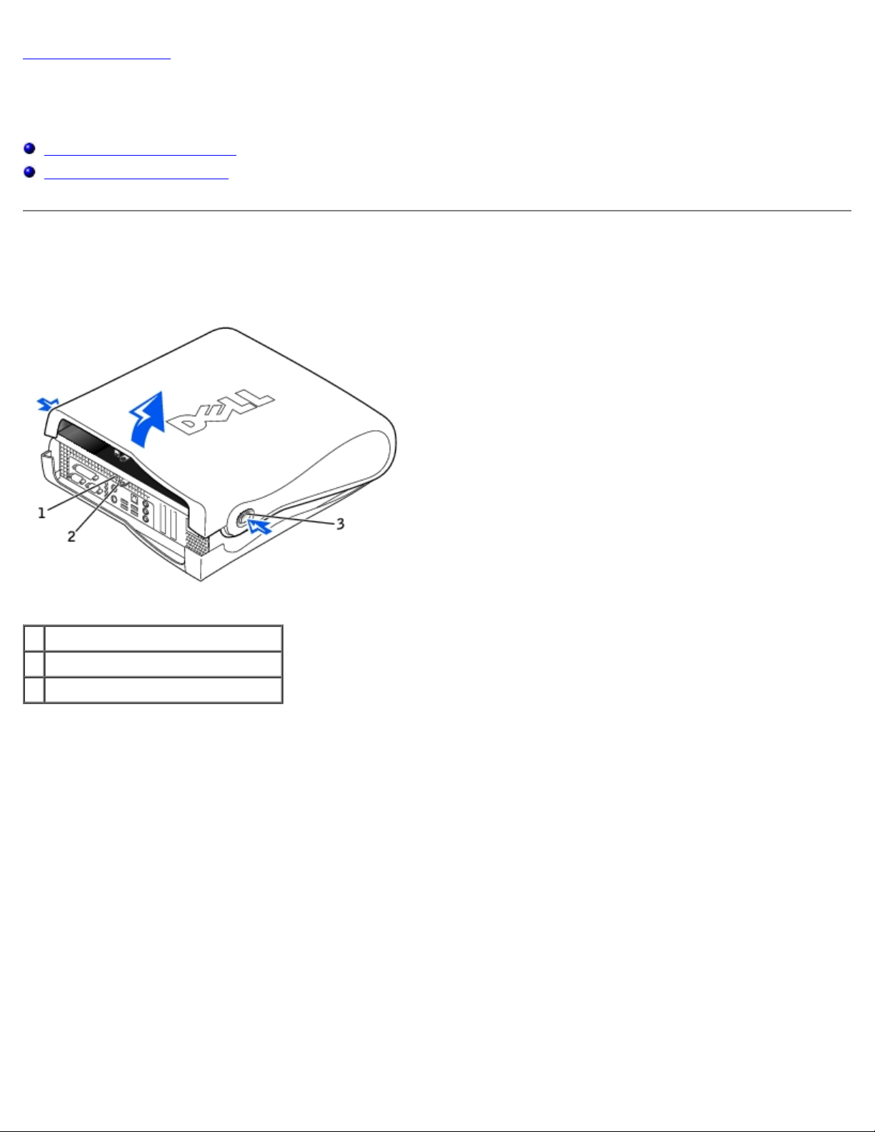
Small Form-Factor Computer
1 security cable slot
2 padlock ring
3 release buttons (one on each side)
Small Desktop Computer
Page 5
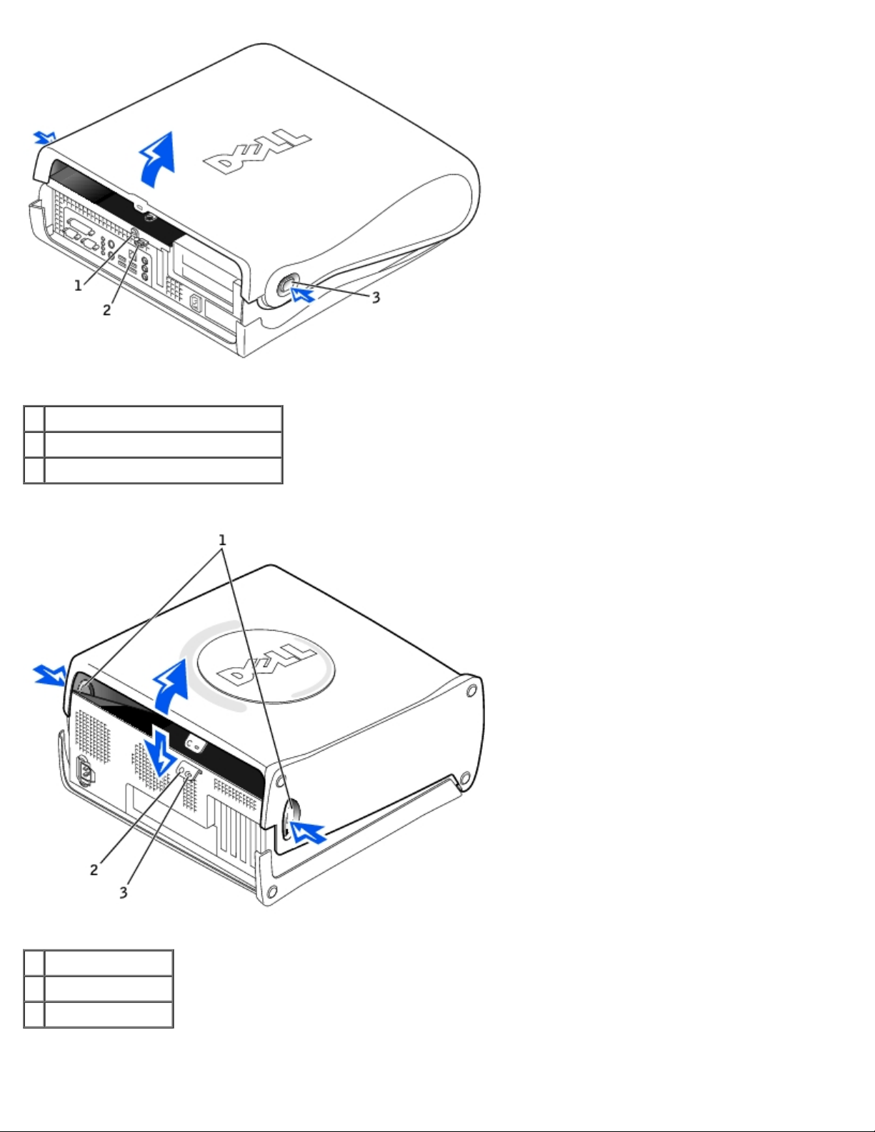
1 security cable slot
2 padlock ring
3 release buttons (one on each side)
Small Mini-Tower Computer
1 release buttons
2 security cable slot
3 padlock ring
1. Remove the padlock from the padlock ring, if present.
Page 6

NOTICE: Ensure that sufficient space exists to support the open cover—at least 30 cm (1 ft) of desktop space.
NOTICE: Open the computer cover slowly to prevent damage to the system cables.
2. To open the cover on the small form-factor or small desktop computer:
a. Remove the computer stand, if it is attached.
b. Locate the two release buttons shown in the illustration, and then press the two release buttons as you lift the
cover.
c. Raise the back of the cover, and pivot it toward the front of the computer.
3. To open the cover on the small mini-tower computer:
a. Lay the computer on its side as shown in the illustration.
b. Facing the back of the computer, press the release button on the right side of the computer with one hand while
pulling up on the top of the cover with the other hand.
c. Press the release button on the left side of the computer with one hand while pulling up on the top of the cover
with the other hand.
d. Hold the bottom of the computer with one hand, and then pull open the cover with the other hand.
Closing the Computer Cover
1. Check all cable connections, especially those that might have come loose during your work. Fold cables out of the way
so that they do not catch on the computer cover.
Gently pull the power cables toward you so that they do not get caught underneath the drives.
2. Check to see that no tools or extra parts (including screws) are left inside the computer.
3. Close the cover:
a. Pivot the cover down.
b. Press down on the right side of the cover until it closes.
c. Press down on the left side of the cover until it closes.
d. Make sure both sides of the cover are locked. If not, repeat this step.
4. Replace the padlock, if required.
Back to Contents Page
Page 7
Back to Contents Page
Inside Your Computer
Dell™ OptiPlex™ GX260 Service Manual
Key Components
Computer Cables
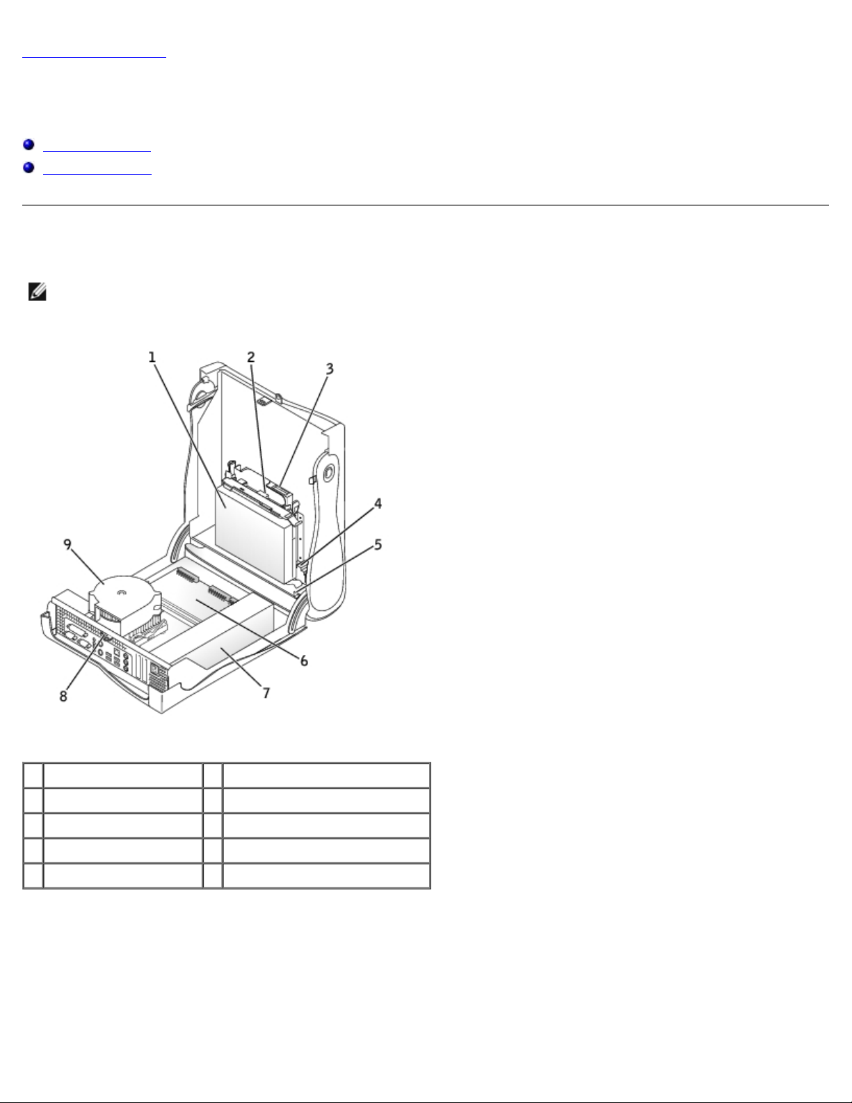
Key Components
NOTE: User service access points are color-coded green.
Small Form-Factor Computer
1 hard drive 6 system board
2 floppy drive 7 power supply
3 CD/DVD drive 8 padlock ring
4 internal speaker 9 heat sink and blower assembly
5 chassis intrusion switch
Small Desktop Computer
Page 8
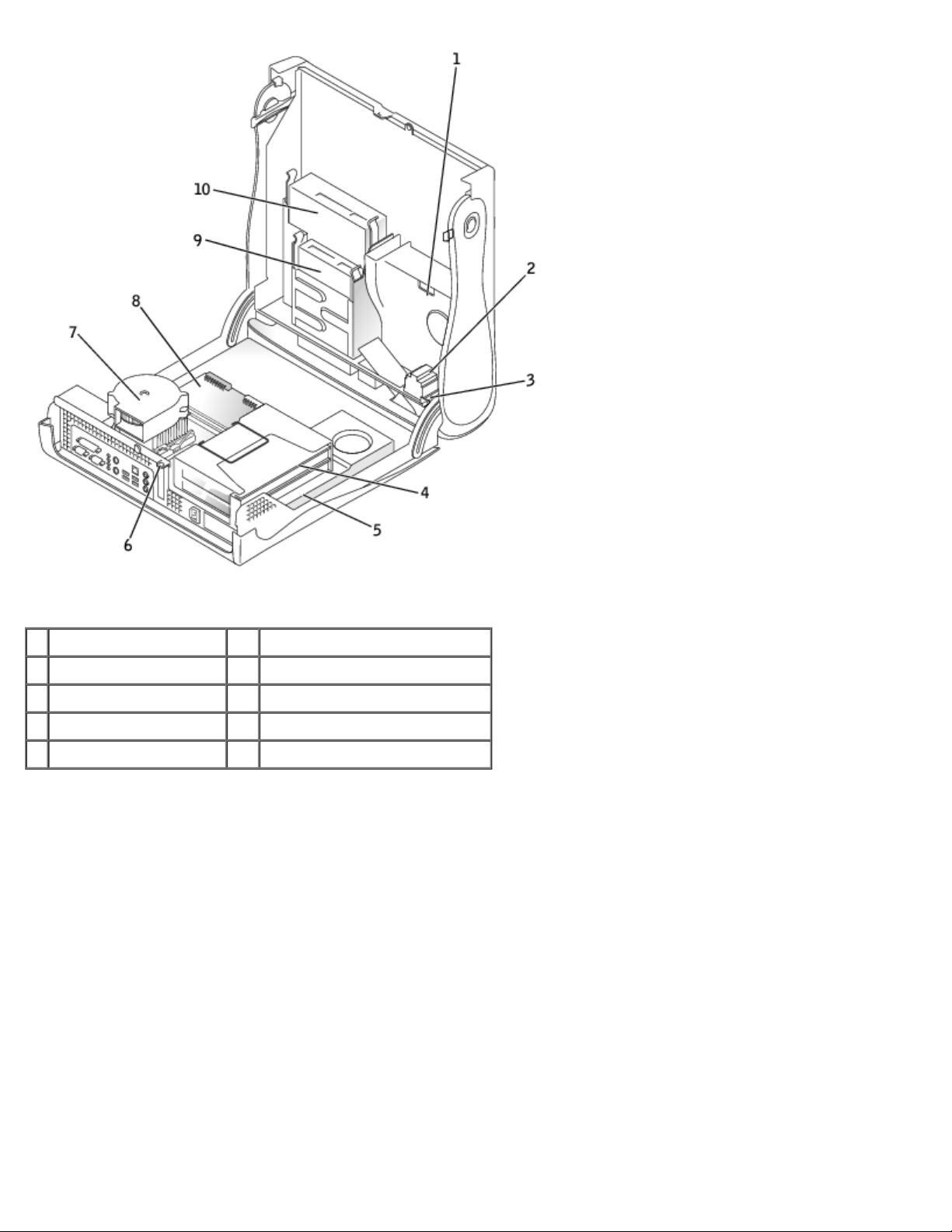
1 hard drive 6 padlock ring
2 internal speaker 7 heat sink and blower assembly
3 chassis intrusion switch 8 system board
4 card cage 9 floppy drive
5 power supply 10 CD/DVD drive
Small Mini-Tower Computer
Page 9
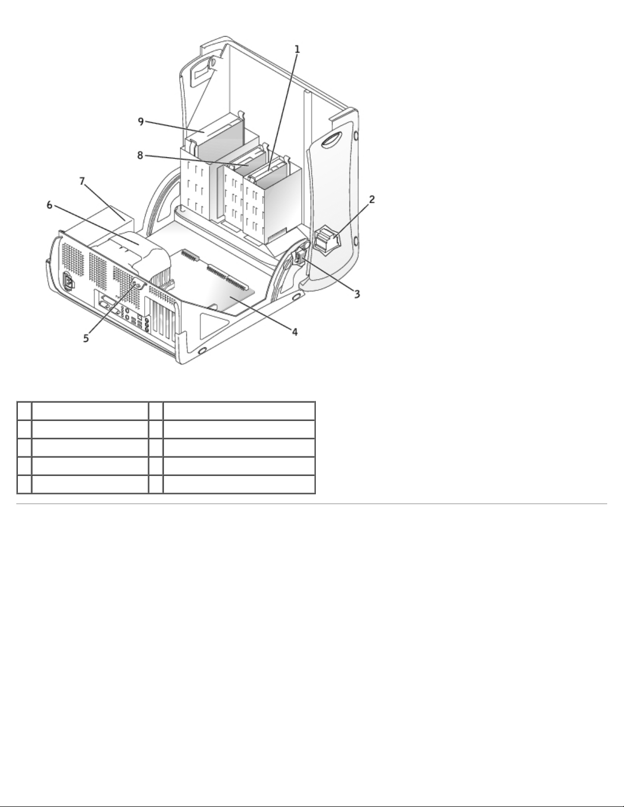
1 hard drive 6 heat sink and blower assembly
2 internal speaker 7 power supply
3 chassis intrusion switch 8 floppy drive
4 system board 9 CD/DVD drive
5 padlock ring
Computer Cables
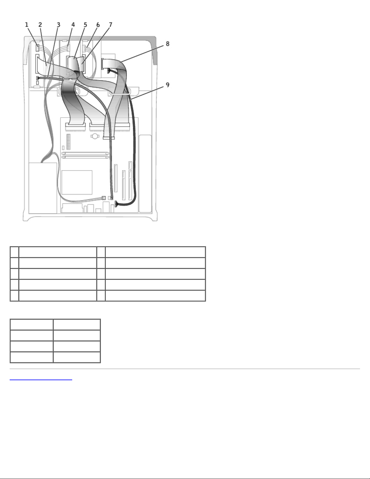
Small Form-Factor Computer
Page 10
1 CD/DVD drive data cable 6 IDE data cable (hard drive)
2 floppy-drive data cable 7 input/output cable
3 control-panel cable 8 input/output audio cable
4 CD/DVD drive power cable 9 microprocessor power cable
5 IDE drive power cable (hard drive) 10 CD/DVD audio cable
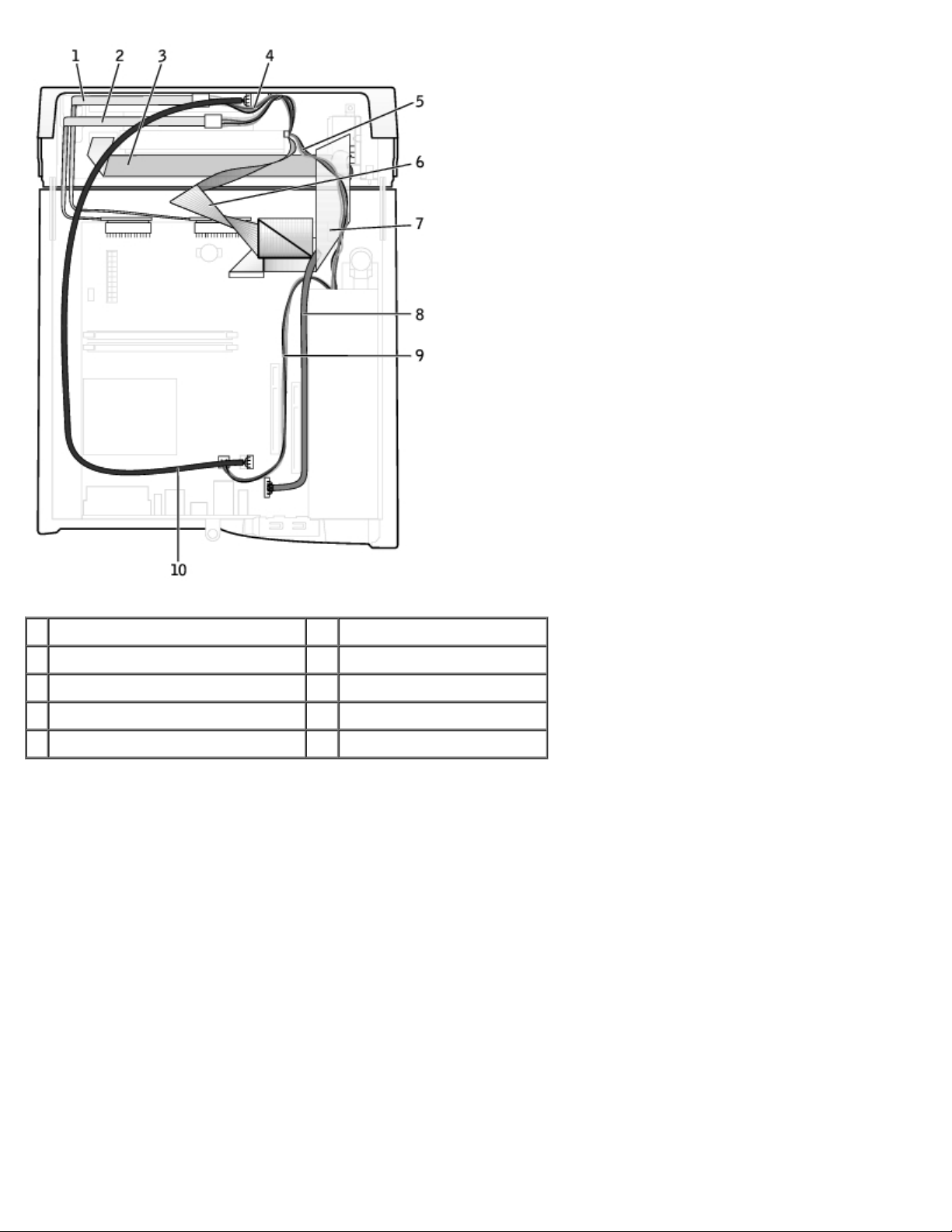
Small Desktop Computer
Page 11
1 CD/DVD drive audio cable 5 input/output cable
2 CD/DVD drive data cable 6 input/output audio cable
3 floppy-drive data cable 7 IDE data cable (hard drive)
4 control-panel cable
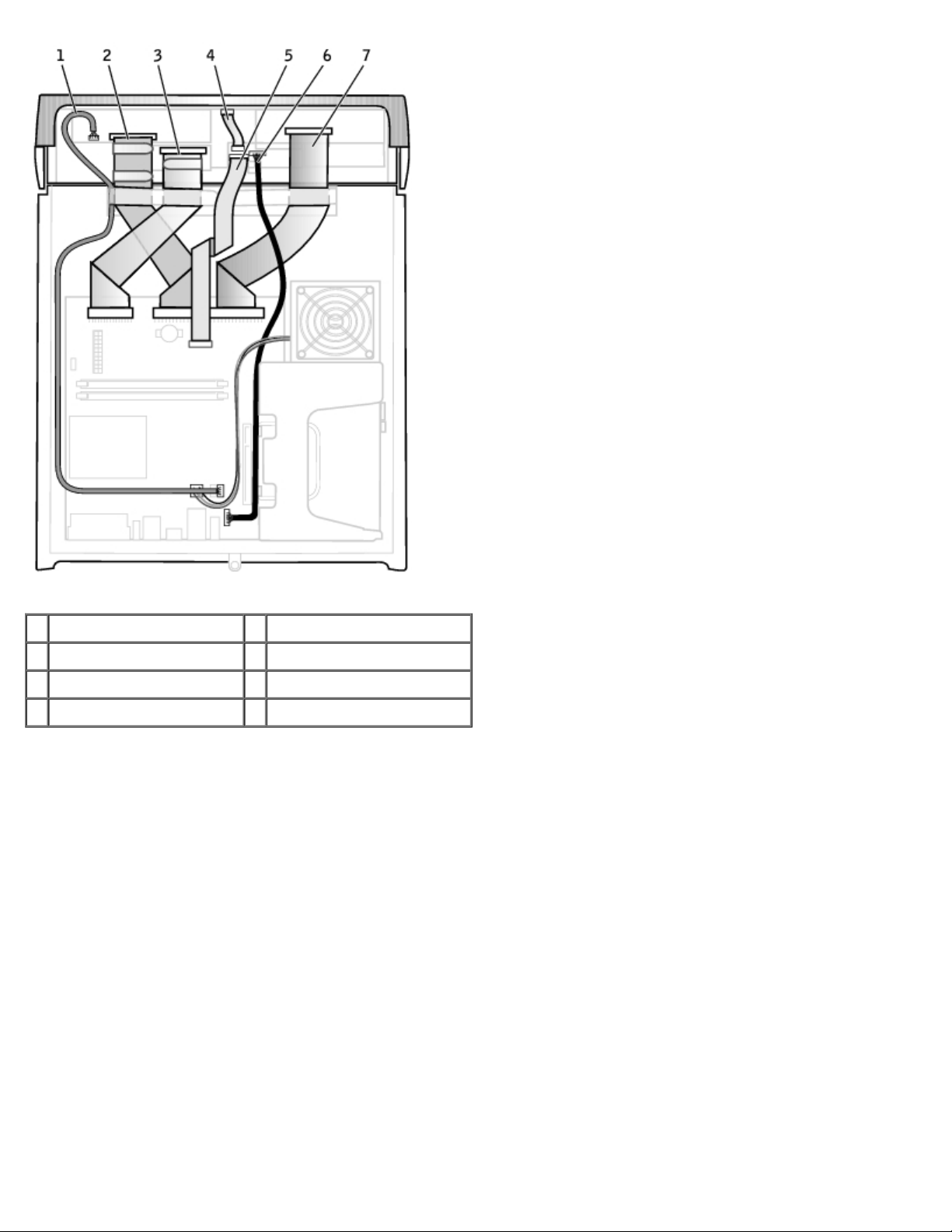
Small Mini-Tower Computer
Page 12
1 CD/DVD drive power cable 6 IDE drive power cable (hard drive)
2 CD/DVD drive data cable 7 IDE drive data cable (hard drive)
3 CD/DVD drive audio cable 8 input/output cable
4 floppy-drive power cable 9 input/output audio cable
5 floppy-drive data cable
Cable Colors
Device Color
Hard drive Blue pull tab
Floppy drive Black pull tab
CD/DVD drive Orange pull tab
Back to Contents Page
Page 13
Back to Contents Page
Badge
Dell™ OptiPlex™ GX260 Service Manual
Removing the Badge
Replacing the Badge
Small Desktop and Small Mini-Tower Computers
Removing the Badge
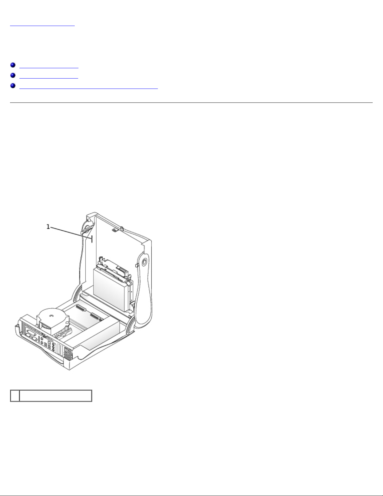
Small Form-Factor Computer
1. Open the computer cover.
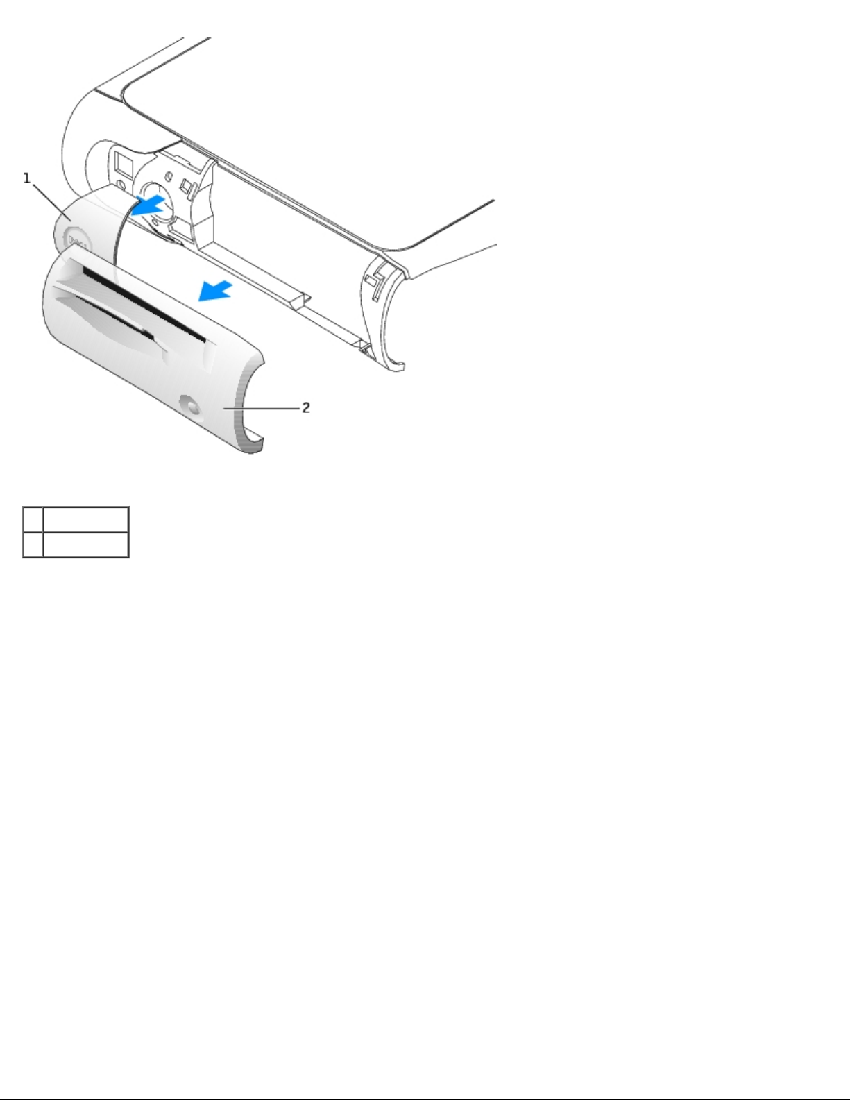
2. Using a flat-blade screwdriver, release the tabs from the inside of the computer, and remove the plastic computer
cover from the metal component.
Computer Cover Removal
1 tabs (two on each side)
3. Remove the accent door by pressing the middle of the door while lifting away the sides of the door.
4. From inside the front bezel, push in on the two tabs on either side of the badge to release the badge.
5. Press the badge until it is freed.
Small Desktop and Small Mini-Tower Computers
Page 14
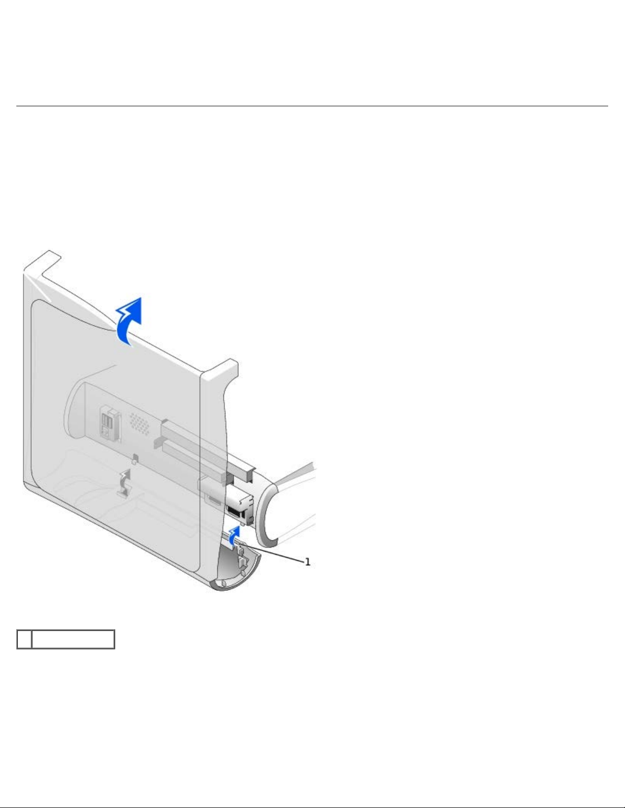
1. Open the front USB door.
2. From inside the door, push in the two tabs on either side of the badge to release the badge.
3. Press the badge until it is freed.
Replacing the Badge
Small Form-Factor Computer
1. Replace the plastic computer cover. Make sure that the two metal hooks and tabs are securely in place.
Computer Cover Replacement
1 metal hooks (2)
To help replace the plastic computer cover, remove the accent door and front mask from the plastic computer cover:
a. Remove the front mask by releasing the tabs on the inside of the plastic computer cover.
b. Remove the accent door by pressing the middle of the door while lifting away the sides of the door.
c. After replacing the plastic computer cover, snap the front mask and accent door into place.
Front Mask and Accent Door Removal
Page 15
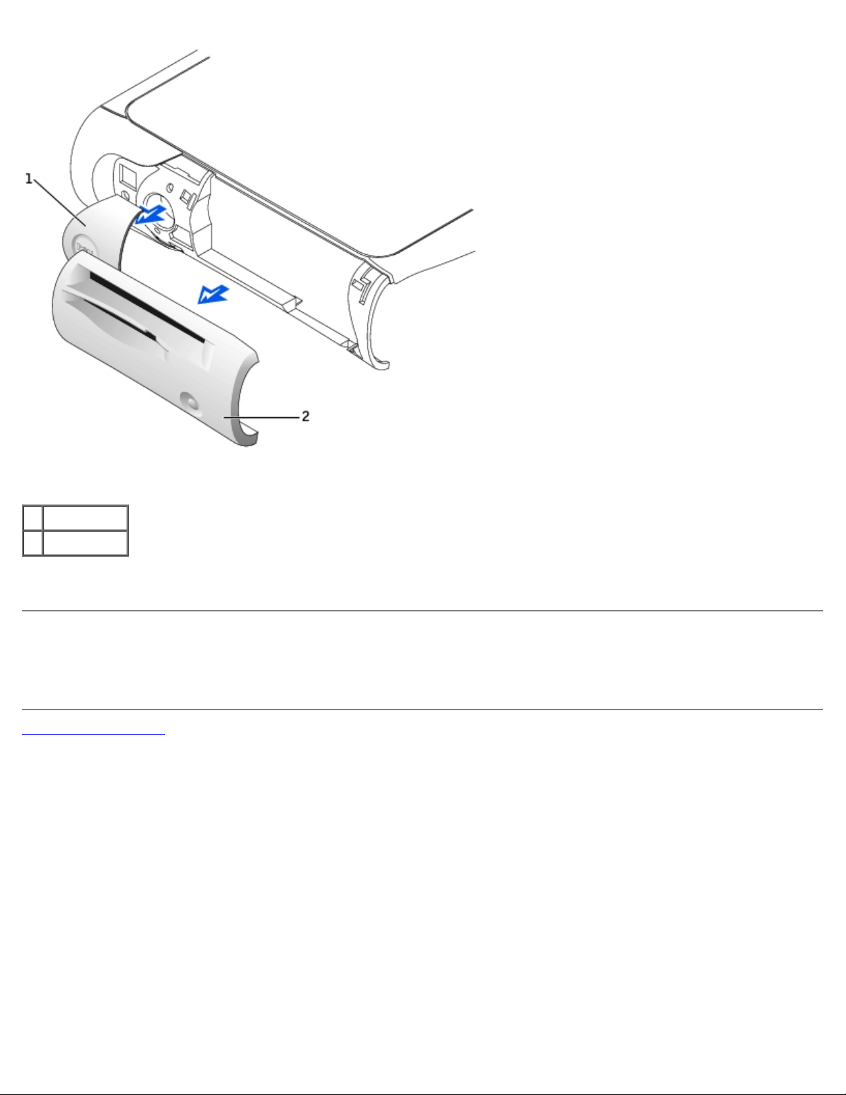
1 accent door
2 front mask
2. Replace the badge by pressing it into place, ensuring that the two tabs click, securing it into position.
Small Desktop and Small Mini-Tower Computers
Replace the badge by pressing it into place, ensuring that the two tabs click, securing it into position.
Back to Contents Page
Page 16
Back to Contents Page
Battery
Dell™ OptiPlex™ GX260 Service Manual
Replacing the Battery
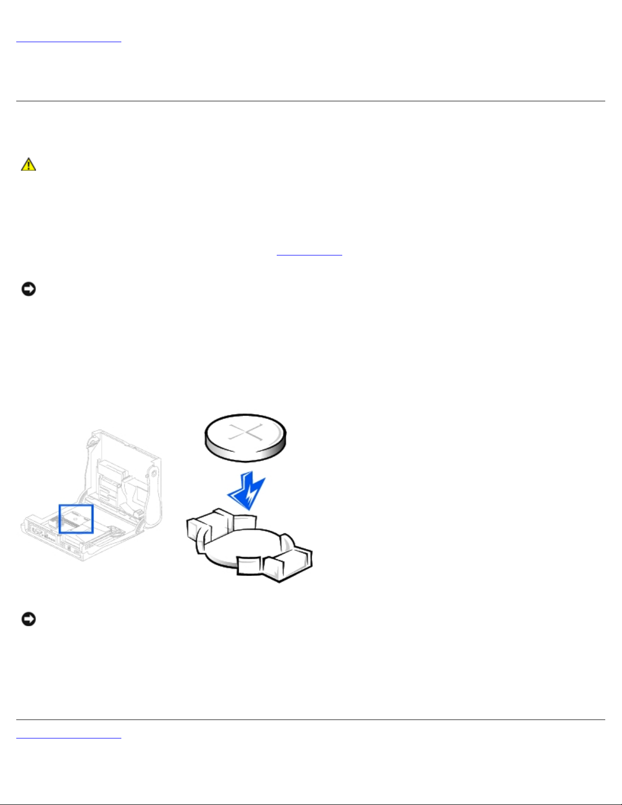
CAUTION: A new battery can explode if it is incorrectly installed. Replace the battery only with the same
or equivalent type recommended by the manufacturer. Discard used batteries according to the
manufacturer's instructions.
1. If you have not already done so, make a copy of your configuration information, found in system setup.
2. Open the computer cover.
3. Locate the battery socket labeled BATTERY (see "System Board
NOTICE: If you pry the battery out of its socket with a blunt object, be careful not to touch the system board with the
object. Ensure that the object is inserted between the battery and the socket before you attempt to pry out the
battery. Otherwise, you may damage the system board by prying off the socket or by breaking circuit traces on the
system board.
4. Remove the battery by carefully prying it out of its socket with your fingers or with a blunt, nonconducting object such
as a plastic screwdriver.
5. Insert the new battery into the socket with the side labeled "+" facing up, and snap the battery into place.
").
NOTICE: To connect a network cable, first plug the cable into the network wall jack, and then plug it into the
computer.
6. Close the computer cover, and plug your computer and devices into electrical outlets.
7. Replace the padlock, if required.
8. Properly dispose of the old battery.
Back to Contents Page
Page 17

Page 18
Back to Contents Page
Chassis Intrusion Switch
Dell™ OptiPlex™ GX260 Service Manual
Removing the Chassis Intrusion Switch
Replacing the Chassis Intrusion Switch
Resetting the Chassis Intrusion Detector
Removing the Chassis Intrusion Switch
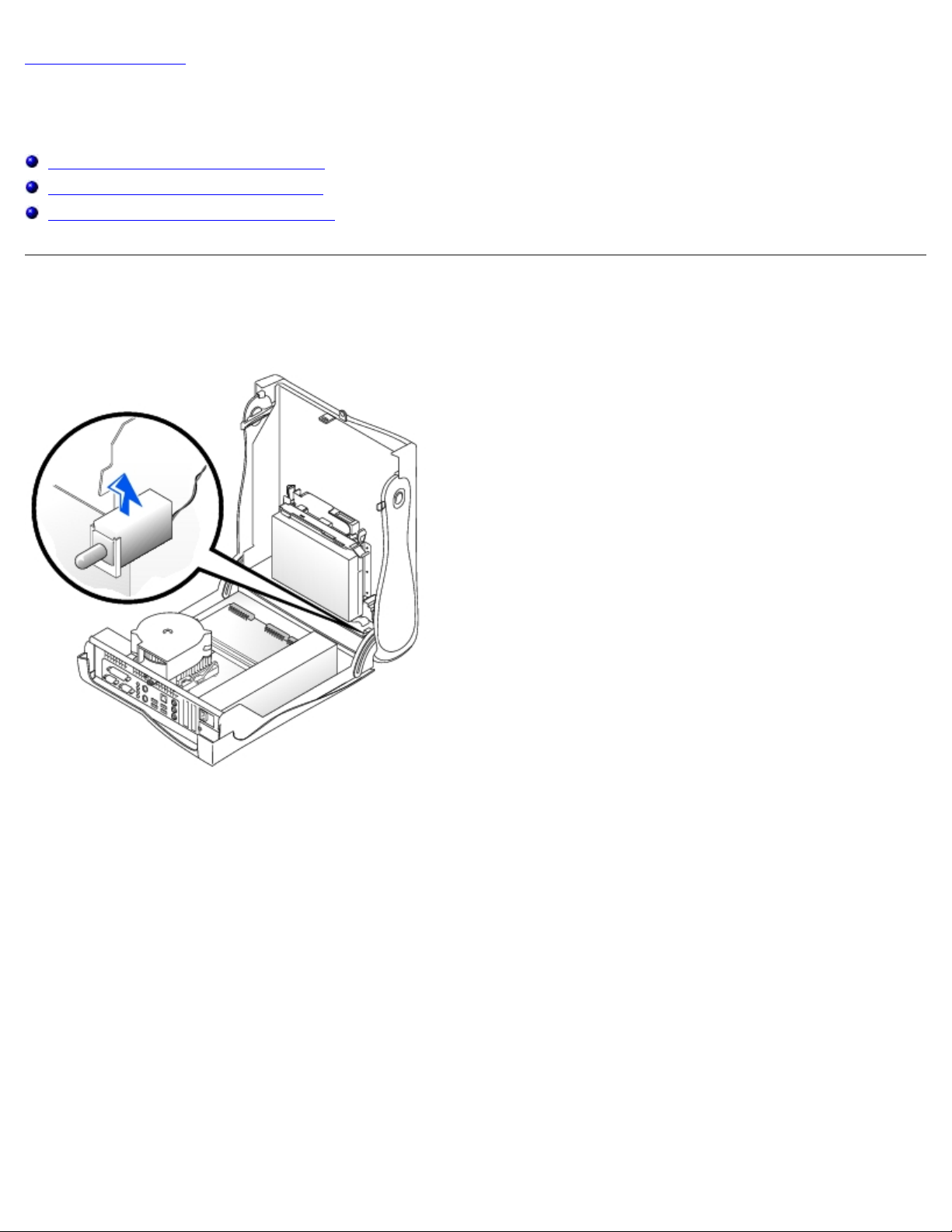
Small Form-Factor Computer
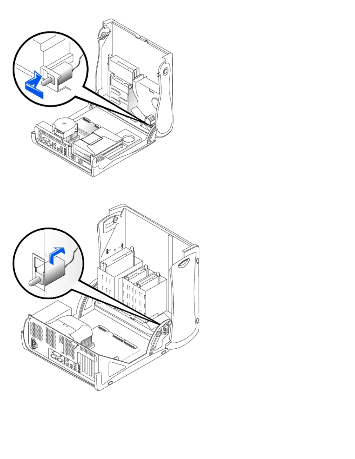
Small Desktop Computer
Page 19
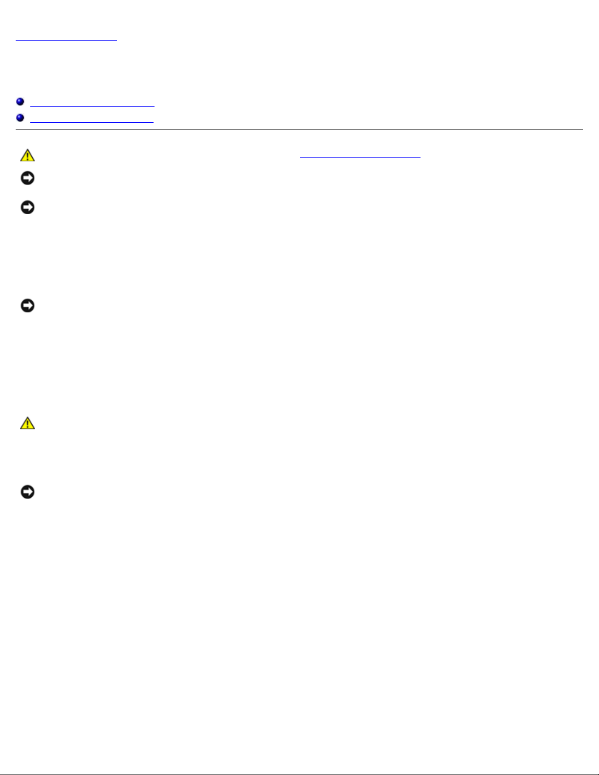
Small Mini-Tower Computer
1. Disconnect the chassis intrusion switch cable connector from the control panel on the front of the chassis.
Note the routing of the chassis intrusion cable as you remove it from the chassis. Chassis hooks may hold the cable in
place inside the chassis.
Page 20

2. Slide the chassis intrusion switch out of its slot and remove the switch and its attached cable from the chassis.
Replacing the Chassis Intrusion Switch
To replace the chassis intrusion switch, follow the "Removing the Chassis Intrusion Switch" procedures in reverse order.
Resetting the Chassis Intrusion Detector
1. Enter system setup by pressing <F2> during the computer's POST.
NOTE: For instructions on using system setup, see the User's Guide.
2. Under the System Security tab, reset the Chassis Intrusion option by pressing the left- or right-arrow key to select
Reset. Change the setting to Enabled, Enabled-Silent, or Disabled.
NOTE: The default is Enabled-Silent.
NOTE: If a setup password has been assigned by someone else, contact the network administrator for information on
resetting the chassis intrusion detector.
3. Press <Alt><B> to restart the computer and implement your changes.
Back to Contents Page
Page 21
Back to Contents Page
Control Panel
Dell™ OptiPlex™ GX260 Service Manual
Removing the Control Panel
Replacing the Control Panel
CAUTION: Before you perform this procedure, see "Precautionary Measures."
NOTICE: To avoid electrostatic discharge, ground yourself by using a wrist grounding strap or by periodically touching
an unpainted metal surface (such as the back panel) on the computer.
NOTICE: Before you disconnect a device from the computer or remove a component from the system board, verify
that the standby power light on the system board has turned off. To locate the light, see "System Board Components."
1. Shut down the computer through the Start menu.
2. Ensure that your computer and attached devices are turned off. If your computer and attached devices did not
automatically turn off when you shut down your computer, turn them off now.
NOTICE: To disconnect a network cable, first unplug the cable from your computer and then unplug it from the
network wall jack.
3. Disconnect any telephone or telecommunication lines from the computer.
4. Disconnect your computer and all attached devices from their electrical outlets, and press the power button to ground
the system board.
5. Remove the computer stand, if it is attached.
CAUTION: To guard against electrical shock, always unplug your computer from the electrical outlet before
opening the cover.
6. Open the computer cover.
NOTICE: Before touching anything inside your computer, ground yourself by touching an unpainted metal surface,
such as the metal at the back of the computer. While you work, periodically touch an unpainted metal surface to
dissipate any static electricity that could harm internal components.
Removing the Control Panel
Small Form-Factor Computer
1. Using a flat-blade screwdriver, release the four tabs from the inside of the computer, and remove the computer cover
from the computer.
Page 22
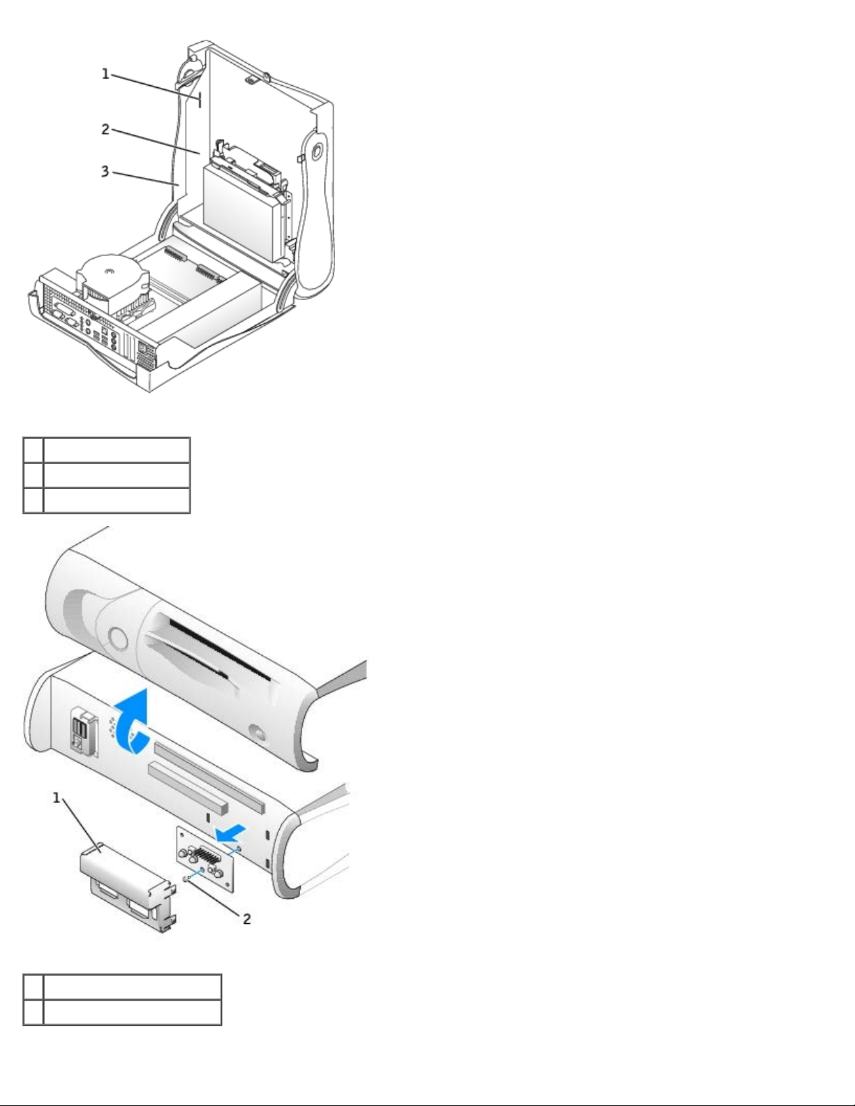
1 tabs (2 on each side)
2 computer
3 computer cover
1 metal control-panel shield
2 screw
2. Remove the metal control-panel shield.
Page 23
3. Remove the screw that holds the control panel to the computer, and remove the control panel.
Small Desktop Computer
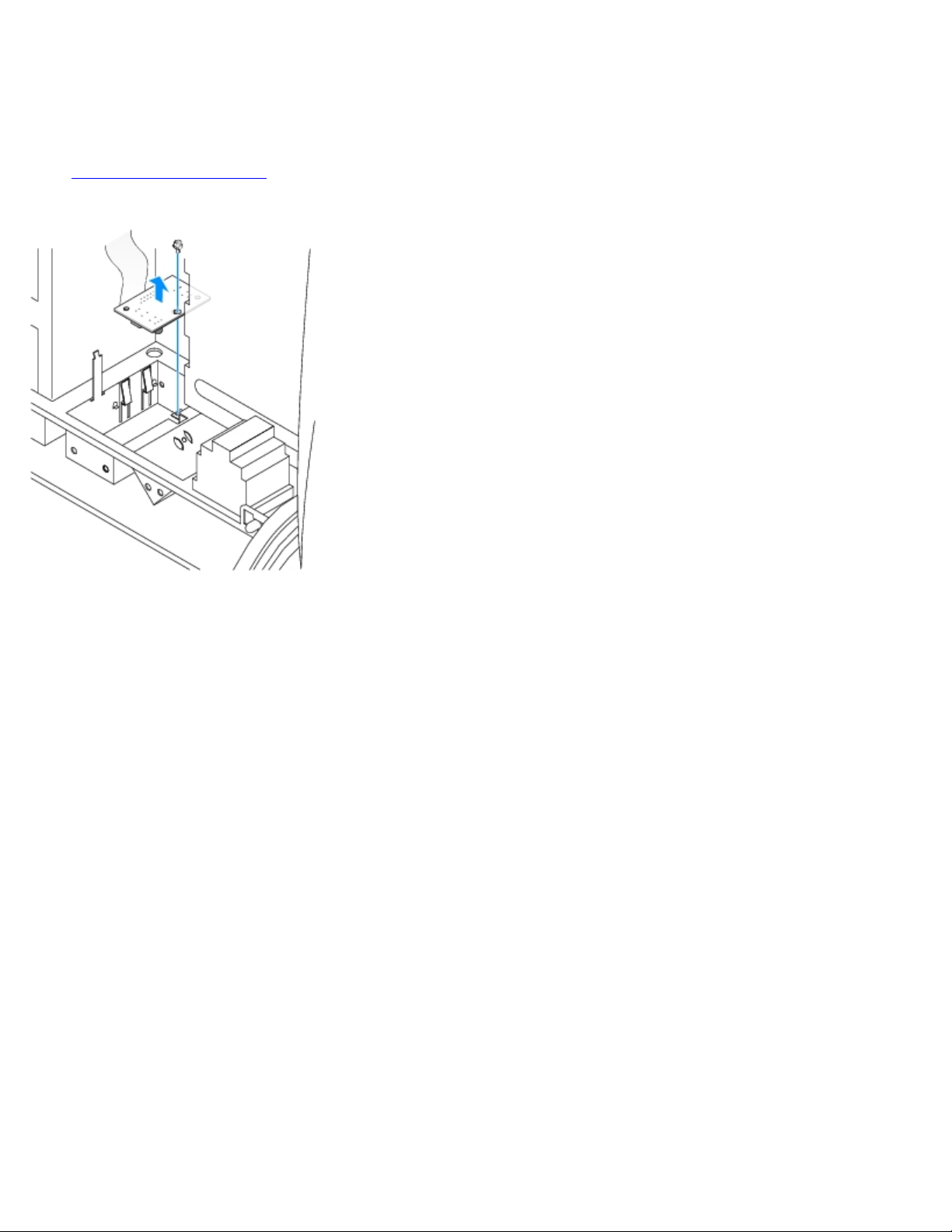
1. Remove the front I/O panel.
2. Using an 8-inch #2 Phillips screwdriver, remove the screw that secures the control panel to the computer, and lift the
panel away from the computer.
Small Mini-Tower Computer
1. To remove the top and bottom panels of the computer, remove any installed CD drives and release all the tabs on each
panel.
Page 24
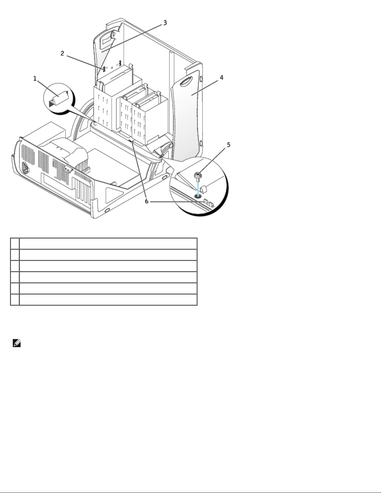
1 computer cover tab (remove the CD drive to access this tab)
2 top-panel tabs
3 top panel
4 bottom panel
5 computer cover screw
6 computer cover tabs (2)
2. To prepare the computer cover for removal, release the three computer cover tabs (one tab is located by the CD drive
and two tabs are located by the I/O panel).
NOTE: To release the tab located by the CD drive, you can pry the computer cover away from the computer and pull
out the tab.
3. If necessary, remove the computer cover screw.
4. Close the computer and remove the computer cover.
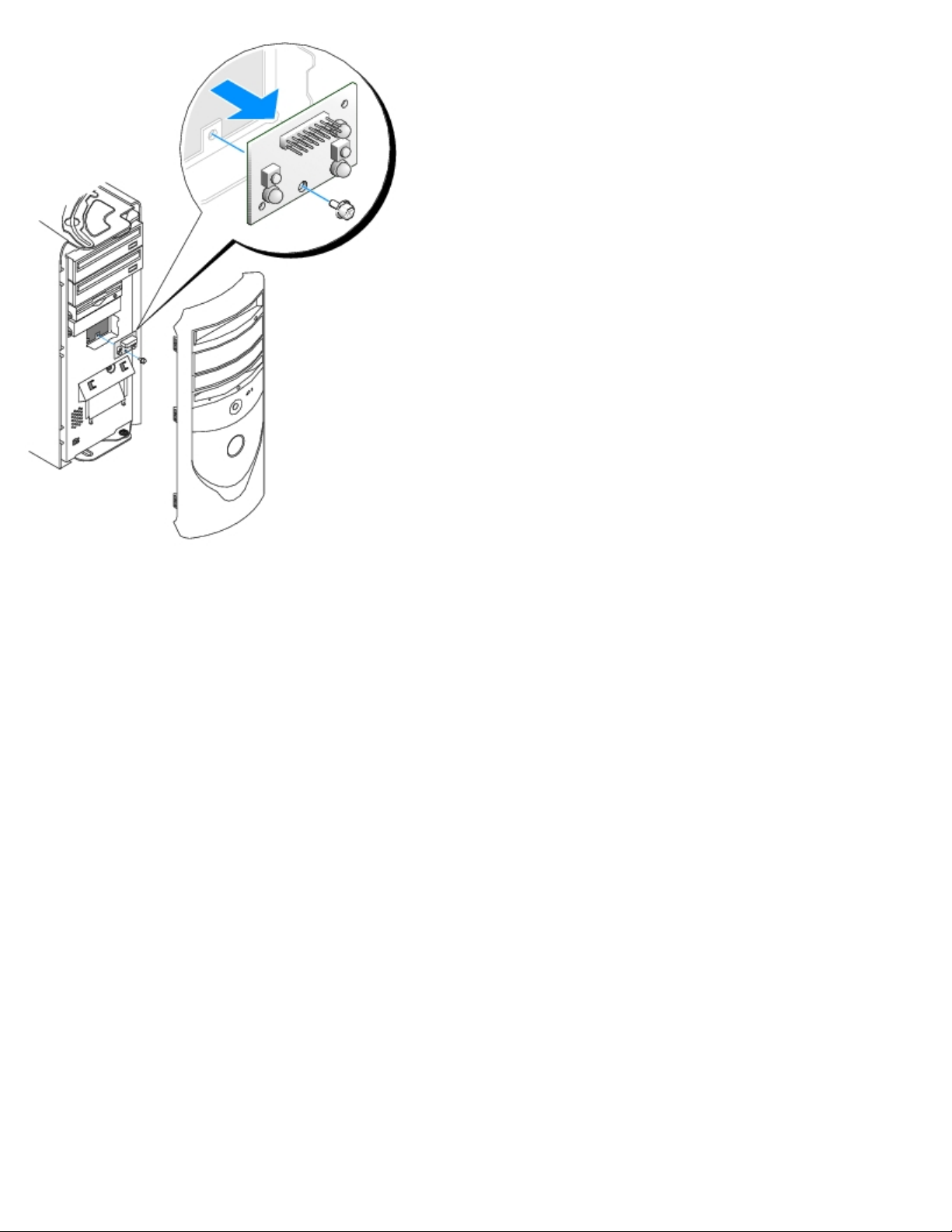
5. Remove the screw that secures the control panel to the computer, and pull the control panel away from the computer.
Page 25
Replacing the Control Panel
Small Form-Factor Computer
1. Replace the control panel and the control-panel shield.
2. Replace the computer cover. Ensure that the two metal hooks and tabs are securely in place.
To help replace the computer cover, remove the accent door and front mask from the computer cover:
a. Remove the front mask by releasing the tabs on the inside of the computer cover.
b. Remove the accent door by pressing the middle of the door while you lift away the sides of the door.
Page 26
1 accent door
2 front mask
3. Replace the computer cover and ensure that the two metal hooks and tabs are securely in position.
Page 27
1 metal hooks (2)
4. To replace the front mask and accent door, press them into position.
Small Desktop Computer
Follow the steps in the "Removing the Control Panel" procedure in the reverse order, ensuring that all tabs are secure.
Small Mini-Tower Computer
Follow the steps in the "Removing the Control Panel" procedure in the reverse order, ensuring that all tabs are secure.
Back to Contents Page
Page 28
Back to Contents Page
Cards and Adapters
Dell™ OptiPlex™ GX260 Service Manual
Small Form-Factor Computer
Small Desktop Computer
Small Mini-Tower Computer
Your computer provides slots for the following cards:
In the small form-factor computer, one low-profile, 32-bit, 33-MHz PCI card or serial port adapter; one DVI adapter
card or one 32-bit, low-profile AGP 4x card operating at 1.5 V.
In the small desktop computer, two 32-bit, 33-MHz PCI cards or one PCI card and one serial port adapter; one DVI
adapter card or one 32-bit, low-profile AGP 4x card operating at 1.5 V.
In the small mini-tower computer, four 32-bit, 33-MHz PCI cards or three PCI cards and one serial port adapter; one
DVI adapter card or one 32-bit, AGP 4x card operating at 1.5 V.
NOTE: Before disconnecting a device from the computer or removing a component from the system board, verify that
the auxiliary power light on the system board is off. For the location of this light, see "System Board
."
Small Form-Factor Computer
PCI Cards
Serial Port Adapters
AGP and DVI Adapter Cards
PCI Cards
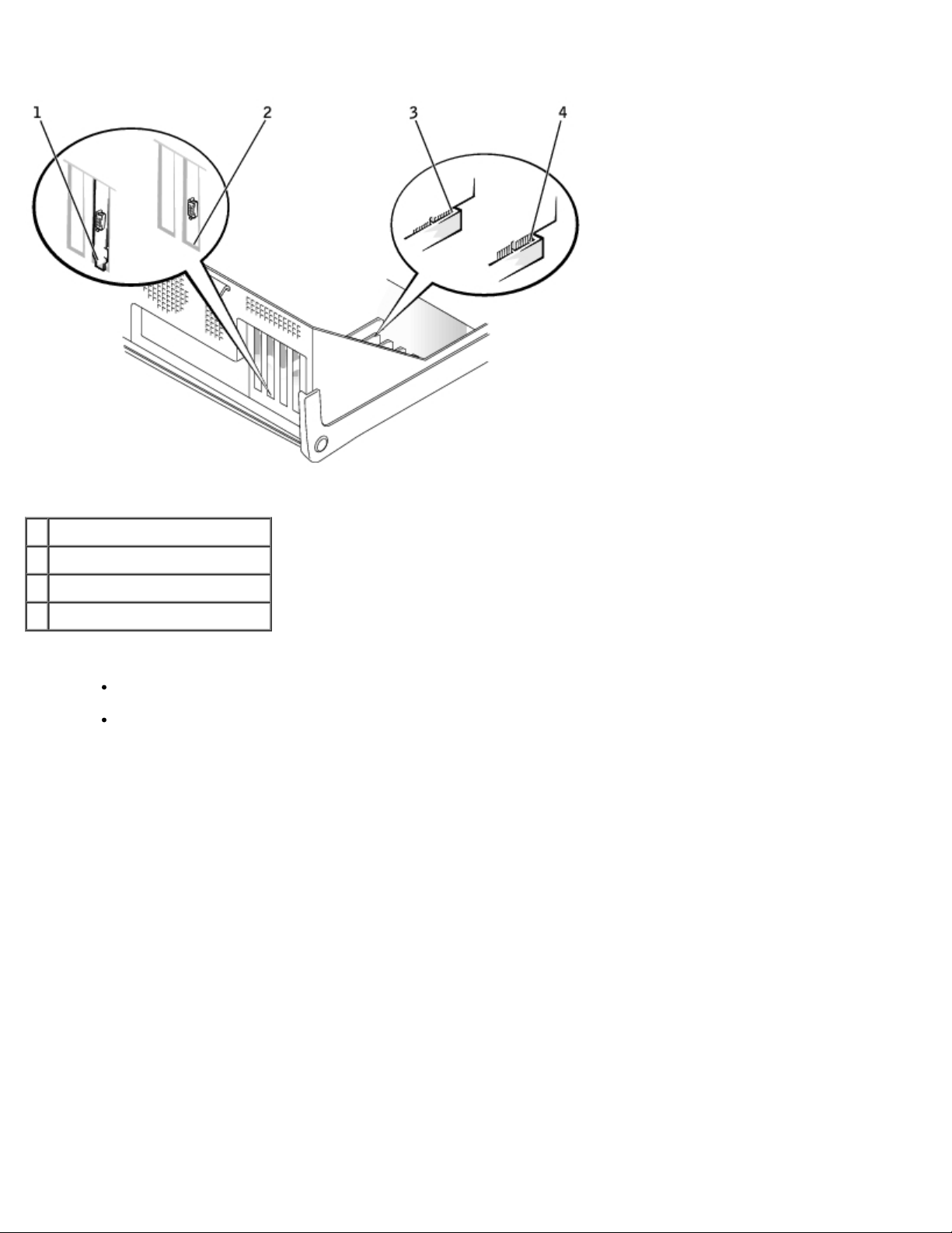
Installing a PCI Card
CAUTION: Before you perform this procedure, see "Precautionary Measures."
1. If you are replacing a card, remove the current driver for the card from the operating system.
2. Raise the retention arm.
Raising the Retention Arm
Page 29
1 edge connector
2 card
3 retention arm
4 card connector
5 filler bracket
3. If you are installing a new card, remove the filler bracket to create an empty card-slot opening, then continue with
.
step 5
4. If you are replacing a card that is already installed in the computer, remove the card (see "Removing a PCI Card
If necessary, disconnect any cables connected to the card. Grasp the card by its top corners, and ease it out of its
connector.
5. Prepare the card for installation.
See the documentation that came with the card for information on configuring the card, making internal connections, or
otherwise customizing it for your computer.
CAUTION: Some network adapters automatically start the computer when they are connected to a
network. To guard against electrical shock, be sure to unplug your computer from its electrical outlet
before installing any cards. Verify that the standby power light on the system board is off. To locate this
light, see "System Board
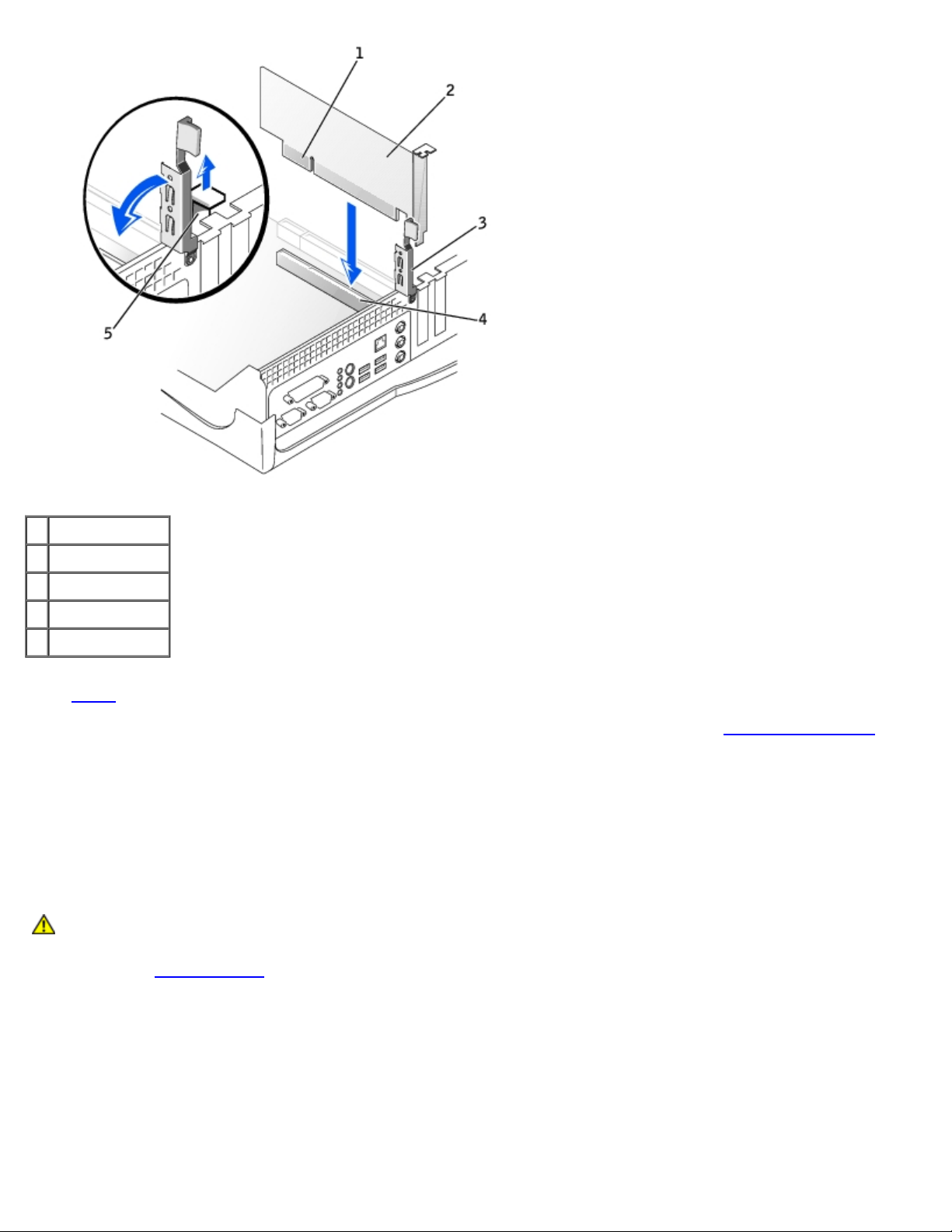
6. Place the card on the connector and press down firmly. Ensure that the card is fully seated in the slot.
If the card is full-length, insert the end of the card into the card guide bracket as you lower the card toward its
connector on the system board. Insert the card firmly into the card connector on the system board.
."
Card Connection
").
Page 30
1 bracket caught outside of slot
2 bracket within slot
3 fully seated card
4 not fully seated card
7. Before you lower the retention arm, ensure that:
The tops of all cards and filler brackets are flush with the alignment bar.
The notch in the top of the card or filler bracket fits around the alignment guide.
Press the arm into place, securing the card(s) in the computer.
Closing the Retention Arm
Page 31

1 alignment guide
2 alignment bar
3 retention arm
4 filler bracket
NOTICE: Do not route card cables over or behind the cards. Cables routed over the cards can prevent the computer
cover from closing properly or cause damage to the equipment.
8. Connect any cables that should be attached to the card.
9. Install any drivers required for the card as described in the card documentation.
Removing a PCI Card
CAUTION: Before you perform this procedure, see "Precautionary Measures."
1. Press the lever on the card retention arm and raise the retention arm.
2. If necessary, disconnect any cables connected to the card.
3. Grasp the card by its top corners, and ease it out of its connector.
4. If you are removing the card permanently, install a filler bracket in the empty card-slot opening.
If you need a filler bracket, contact Dell.
NOTE: Installing filler brackets over empty card-slot openings is necessary to maintain FCC certification of the
computer. The brackets also keep dust and dirt out of your computer.
5. Lower the retention arm and press it into place.
6. Remove the card's driver from the operating system.
Page 32

Serial Port Adapters
Installing a Serial Port Adapter
CAUTION: Before you perform this procedure, see "Precautionary Measures."
1. Lift the tab on the card retention arm and raise the retention arm (see "Raising the Retention Arm
2. Remove the filler bracket.
3. Slide the card bracket down over the card-slot opening, and ensure that the top of the card bracket is flush with the
alignment bar and the notch in the top of the card bracket fits around the alignment guide (see "Closing the Retention
Arm").
4. Attach the serial card cable to the connector on the system board (labeled SER2).
").
Installing a Serial Port Adapter
1 SER2 system board
connector
2 card bracket
3 serial card cable
4 card-slot opening
Page 33

5. Lower the retention arm into place, securing the card(s) in the computer (see "Closing the Retention Arm").
Removing a Serial Port Adapter
CAUTION: Before you perform this procedure, see "Precautionary Measures."
1. Raise the retention arm.
2. Disconnect the cable from the system board connector.
3. Lift and remove the card bracket.
4. If you are removing the card permanently, install a filler bracket in the empty card-slot opening.
If you need a filler bracket, contact Dell.
NOTE: Installing filler brackets over empty card-slot openings is necessary to maintain FCC certification of the
computer. The brackets also keep dust and dirt out of your computer.
5. Lower the retention arm and press it into place.
AGP and DVI Adapter Cards
CAUTION: Before you perform this procedure, see "Precautionary Measures."
Removing an AGP or DVI Adapter Card
1. Remove the filler bracket by raising the hinged lever and sliding the filler bracket up.
Filler Bracket Removal
1 hinged lever
2 filler bracket
2. On the card clip, press the card-clip lever toward the card slot.
3. Pull the card up and out of the card clip.
Page 34

Removing the Card
1 card notch
2 card-clip lever
3 card-clip tab
4 card clip
5 card slot
Installing an AGP or DVI Adapter Card
1. To add or replace the card, press the card-clip lever toward the card slot and gently press the card into the slot
connector until it clicks into place.
2. Release the card-clip lever, ensuring that the tab on the card-clip lever fits into the notch on the front end of the card.
3. Secure the card by lowering the hinged lever on the back panel.
4. Close the computer cover.
5. Attach the computer stand (optional).
NOTICE: To connect a network cable, first plug the cable into the network wall jack, and then plug it into the
computer.
6. Connect the monitor cable to the card's video connector.
7. Connect your computer and devices to electrical outlets, and turn them on.
Back to Contents Page
Page 35

Back to Contents Page
Drives
Dell™ OptiPlex™ GX260 Service Manual
Small Form-Factor Computer
Small Desktop Computer
Small Mini-Tower Computer
Small Form-Factor Computer
Hard Drive
Front-Panel Inserts
Floppy Drive
CD/DVD Drive
Hard Drive
CAUTION: Before you perform this procedure, see "Precautionary Measures."
Removing a Hard Drive
1. Disconnect the power cable and hard-drive cable from the drive.
Removing Power and Drive Cables
1 power cable
Page 36

2 hard-drive cable
2. Press in on the tabs on each side of the drive, slide the drive toward the I/O panel, and remove it from the computer.
Removing the Hard Drive
Installing a Hard Drive
1. Unpack the replacement hard drive, and prepare it for installation.
2. If your replacement drive does not have the bracket rails attached, remove the rails from the old drive by removing
the two screws that secure each rail to the drive. Attach the bracket rails to the new drive by aligning the screw holes
on the drive with the screw holes on the bracket rails, and then inserting and tightening all four screws (two screws on
each rail).
Drive Bracket Rails
1 drive
2 bracket rails (2)
3 screws (4)
Page 37

3. Install the hard drive into the computer by gently sliding the drive into place until you hear it securely click.
NOTICE: Match the colored strip on the cable with pin 1 on the drive (pin 1 is marked as "1").
4. Connect the power and hard-drive cables to the drive.
Attaching Power and Drive Cables
1 power cable
2 hard-drive cable
5. Check all connectors to be certain that they are properly cabled and firmly seated.
Front-Panel Inserts
If you are installing a new floppy or CD/DVD drive rather than replacing a drive, remove the front-panel insert.
Front-Panel Insert Removal
Page 38

Floppy Drive
CAUTION: Before you perform this procedure, see "Precautionary Measures."
Removing a Floppy Drive
1. Disconnect the floppy-drive cable from the system board connector (DSKT).
2. Remove the power cable from the interposer board.
3. Disconnect the CD/DVD drive cable and the power cable from the CD/DVD drive.
4. Remove or raise the drive by pressing the green tabs on either side of the drive and lifting the drive up.
5. Remove the floppy-drive cable from the floppy drive.
a. Remove the interposer board from the floppy drive by pressing the tab and rotating the interposer board.
Removing the Interposer Board
1 floppy-drive cable
Page 39

2 tab
3 interposer board
4 system board floppy-drive connector (DSKT)
b. To release the floppy-drive cable from the connector, slide the lever until it is fully extended, and then lift the
cable away.
Removing the Floppy-Drive Cable
1 floppy-drive cable
2 lever
6. Remove the floppy drive from its sled by pulling the sled tab out while pushing the drive up and then sliding the drive
Page 40

out of the sled.
Removing the Floppy Drive
1 sled tab
2 sled
Installing a Floppy Drive
1. Snap the replacement drive into the sled and ensure that it is secure in the sled.
2. Connect the interposer board to the floppy drive.
a. Slide the floppy-drive cable into the connector.
b. Close the lever so that the cable is secure in the connector.
c. Line up the hole on the bottom of the interposer board with the notch on the connector, and snap the interposer
board onto the drive.
3. Gently slide the drive into the computer until the tabs securely click into position.
Attaching the Floppy-Drive Cable
Page 41

1 connector notch
2 interposer board alignment hole
3 floppy-drive cable
4 lever
4. Attach the power cable to the interposer board on the floppy drive.
5. Attach the CD/DVD drive cable and the power cable to the CD/DVD drive.
6. Connect the floppy-drive cable to the DSKT connector on the system board.
7. Check all cable connections, and fold cables out of the way to provide airflow for the fan and cooling vents.
Page 42

CD/DVD Drive
CAUTION: Before you perform this procedure, see "Precautionary Measures."
Removing a CD/DVD Drive
1. Disconnect the power and audio cables from the interposer board.
2. Remove the interposer board from the drive.
Removing the Interposer Board
1 interposer board
3. Press inward on the two tabs on the sides of the drive, and then slide the drive upward and remove it from the drive
bay.
Page 43

Installing a CD/DVD Drive
1. Unpack the drive and prepare it for installation.
Check the documentation that accompanied the drive to verify that the drive is configured for your computer. If you are
installing an IDE drive, configure the drive for the cable-select setting.
2. Gently slide the drive into place until the tabs securely click into position.
3. Connect the interposer board to the CD drive:
a. Ensure that the interposer board tab fits securely under the notch on the inside of the cover.
b. Attach the power and audio cables to the interposer board.
Connecting the Interposer Board
Page 44

1 interposer board
2 notch on inside of cover
3 interposer board tab
If your computer came with an IDE CD drive, use the spare connector on the existing interface cable. Otherwise, use
the IDE interface cable provided in the drive kit.
4. If you are installing a drive that has its own controller card, install the controller card in an expansion slot.
5. Check all cable connections, and fold cables out of the way to provide airflow for the fan and cooling vents.
6. If the CD/DVD drive bay was previously empty, remove the front- panel inserts (see "Front-Panel Inserts
7. Close the computer cover.
8. Attach the computer stand (optional).
").
Page 45

Small Desktop Computer
Hard Drive
Front-Panel Inserts
Floppy Drive
CD/DVD Drive
Hard Drive
CAUTION: Before you perform this procedure, see "Precautionary Measures."
Removing a Hard Drive
1. Your computer's hard drive may or may not have a plastic shroud cover. (Operating the computer without a hard-drive
shroud does not affect its performance.) If your computer's hard drive does not have a shroud, proceed to the next
step. If your computer's hard drive does have a shroud, remove it by pressing in on the indented tab at the top of the
shroud and lifting the shroud away
Removing the Hard-Drive Shroud
NOTE: Your computer's hard drive may or may not have a plastic shroud cover. Operating the computer without a
hard- drive shroud does not affect its performance.
2. Disconnect the power and hard-drive cables from the drive.
Removing Power and Drive Cables
Page 46

1 hard-drive cable
2 power cable
3. Press in on the tabs on each side of the drive and slide the drive up and out.
Removing the Hard Drive
1 tabs (2)
2 hard drive
Installing a Hard Drive
Page 47

1. Check the documentation for the drive to verify that it is configured for your computer.
NOTICE: To avoid damage to the drive, do not set it on a hard surface. Instead, set the drive on a surface, such as a
foam pad, that will sufficiently cushion it.
2. Unpack the replacement hard drive, and prepare it for installation.
3. If the replacement drive does not have the bracket rails attached, see step 2
attaching rails.
4. Install the hard drive into the computer by gently sliding the drive into place until you hear it securely click.
NOTICE: Match the colored strip on the cable with pin 1 on the drive (pin 1 is marked as "1").
5. Connect the power and hard-drive cables to the drive.
in the previous section for instructions on
Attaching Power and Drive Cables
1 hard-drive cable
2 power cable
6. Check all connectors to be certain that they are properly cabled and firmly seated.
7. If your computer has a hard-drive shroud, replace the shroud by inserting the two tabs on the bottom into the holes in
the computer and snapping the top into place. (Operating the computer without a hard-drive shroud does not affect its
performance.)
8. Close the computer cover.
9. Attach the computer stand (optional).
Front-Panel Inserts
Page 48

If you are installing a new floppy or CD/DVD drive rather than replacing a drive, remove the front-panel inserts:
1. Facing the front of the computer, use your fingers to remove the front- panel cover.
Removing Front-Panel Inserts
2. Press the inserts until they pop free of the front-panel cover.
Floppy Drive
CAUTION: Before you perform this procedure, see "Precautionary Measures."
Removing a Floppy Drive
1. Disconnect the power and data cables from the CD/DVD drive located above the floppy drive.
Page 49

2. Disconnect the power and floppy-drive cables from the back of the floppy drive.
3. Disconnect the floppy-drive cable from the system board connector (labeled DSKT).
Removing Power and Drive Cables
1 power cable
2 floppy-drive cable
3 floppy-drive connector (DSKT)
4. Press inward on the two tabs on the sides of the drive, slide the drive upward, and remove it from the floppy-drive
bay.
Floppy Drive Removal
Page 50

Installing a Floppy Drive
1. If the replacement drive does not have the bracket rails attached, see step 2 in the previous section for instructions on
attaching rails.
2. Gently slide the drive into place until the tabs securely click into position.
3. Attach the power and floppy-drive cables to the floppy drive.
4. Connect the other end of the floppy-drive cable to the connector labeled DSKT on the system board.
Attaching Power and Drive Cables
1 power cable
2 floppy-drive cable
Page 51

3 floppy-drive connector (DSKT)
3. Press inward on the two tabs on the sides of the drive, and then slide the drive upward and remove it from the drive
5. Reconnect the power and data cables to the back of the drive installed in the CD/DVD drive bay located above the
floppy drive.
6. Check all cable connections, and fold cables out of the way to provide airflow for the fan and cooling vents.
7. Close the computer cover.
8. Attach the computer stand (optional).
CD/DVD Drive
CAUTION: Before you perform this procedure, see "Precautionary Measures."
Removing a CD/DVD Drive
1. Disconnect the power, audio, and CD/DVD drive cables from the back of the drive.
2. Disconnect the other end of the CD/DVD drive cable from the system board connector (IDE2).
Removing Power, Audio, and Drive Cables
1 audio cable
2 power cable
3 CD/DVD drive cable
4 IDE2 connector
Page 52

bay.
Installing a CD/DVD Drive
1. Unpack the drive and prepare it for installation.
Check the documentation that accompanied the drive to verify that the drive is configured for your computer. If you are
installing an IDE drive, configure the drive for the cable-select setting.
2. If the replacement drive does not have the bracket rails attached, see step 2
attaching rails.
3. Gently slide the drive into place until the tabs securely click into position.
4. Connect the power, audio, and CD/DVD drive cables to the drive.
5. Connect the other end of the CD/DVD drive cable to the IDE2 system board connector.
in the previous section for instructions on
Connecting Power, Audio, and Drive Cables
Page 53

1 audio cable
2 power cable
3 CD/DVD drive cable
4 IDE2 connector
6. If you are installing a drive that has its own controller card, install the controller card in a card slot.
7. Check all cable connections, and fold cables out of the way to provide airflow for the fan and cooling vents.
8. If the CD/DVD drive bay was previously empty, remove the front- panel inserts.
9. Close the computer cover.
10. Attach the computer stand (optional).
Small Mini-Tower Computer
Hard Drive
Adding a Second Hard Drive
Front-Panel Inserts
Floppy Drive
CD/DVD Drive
Hard Drive
CAUTION: Before you perform this procedure, see "Precautionary Measures."
Page 54

Removing a Hard Drive
2 hard drive
1. Disconnect the power and hard-drive cables from the drive.
Removing Power and Drive Cables
1 power cable
2 hard-drive cable
2. Press in on the tabs on each side of the drive and slide the drive up and out.
Removing the Hard Drive
1 tabs (2)
Page 55

Installing a Hard Drive
1. Unpack the replacement hard drive, and prepare it for installation.
2. Check the documentation for the drive to verify that it is configured for your computer.
3. If the replacement drive does not have the bracket rails attached, see step 2
attaching rails.
4. Install the hard drive into the computer by gently sliding the drive into place until you hear it securely click.
NOTICE: Match the colored strip on the cable with pin 1 on the drive (pin 1 is marked as "1").
5. Connect the power and hard-drive cables to the drive.
in the previous section for instructions on
Attaching Power and Drive Cables
1 power cable
2 hard-drive cable
6. Check all connectors to be certain that they are properly cabled and firmly seated.
Adding a Second Hard Drive
CAUTION: Before you perform this procedure, see "Precautionary Measures."
1. Remove the two green plastic rails from the inside of the hard-drive bay by gently pulling the rails up and out of the
bay.
2. Attach the rails to the hard drive using the two screws attached to the rails.
Page 56

Ensure that the rail tabs are positioned at the back of the hard drive.
NOTICE: Do not install any drive into the lower hard-drive bay until you have removed the green drive rails from the
inside of the hard-drive bay.
3. Remove the first hard drive from the upper bay and install it in the lower bay:
a. Disconnect the power and the hard-drive cables from the back of the first hard drive.
b. Press in the two green rail tabs and pull the first hard drive out of the upper bay.
c. Gently slide the first hard drive into the lower bay until you hear a click.
d. Reconnect the power and hard-drive cables to the back of the first hard drive.
4. Gently slide the new hard drive into the upper bay until you hear a click.
Installing a Second Hard Drive
1 rail tabs (2)
2 second hard drive in upper bay
3 first hard drive in lower bay
4 hard-drive bay
5. Connect a power cable to the drive.
NOTICE: Match the colored strip on the cable with pin 1 on the drive.
6. Locate the extra connector on the drive cable that is attached to your first hard drive and attach the connector to the
second hard drive.
Your computer uses cable-select drive cables. This means that the device connected to the end connector of the drive
cable is the master device and the device connected to the middle connector is the slave device. Be sure that the
jumper setting on the new device is set for "cable select" (see the documentation that came with the drive for
information).
Attaching Cables
Page 57

1 power cable
2 second hard-drive cable (secondary drive)
3 first hard-drive cable (primary boot drive)
Front-Panel Inserts
If you are installing a new floppy or CD/DVD drive rather than replacing a drive, remove the front-panel inserts.
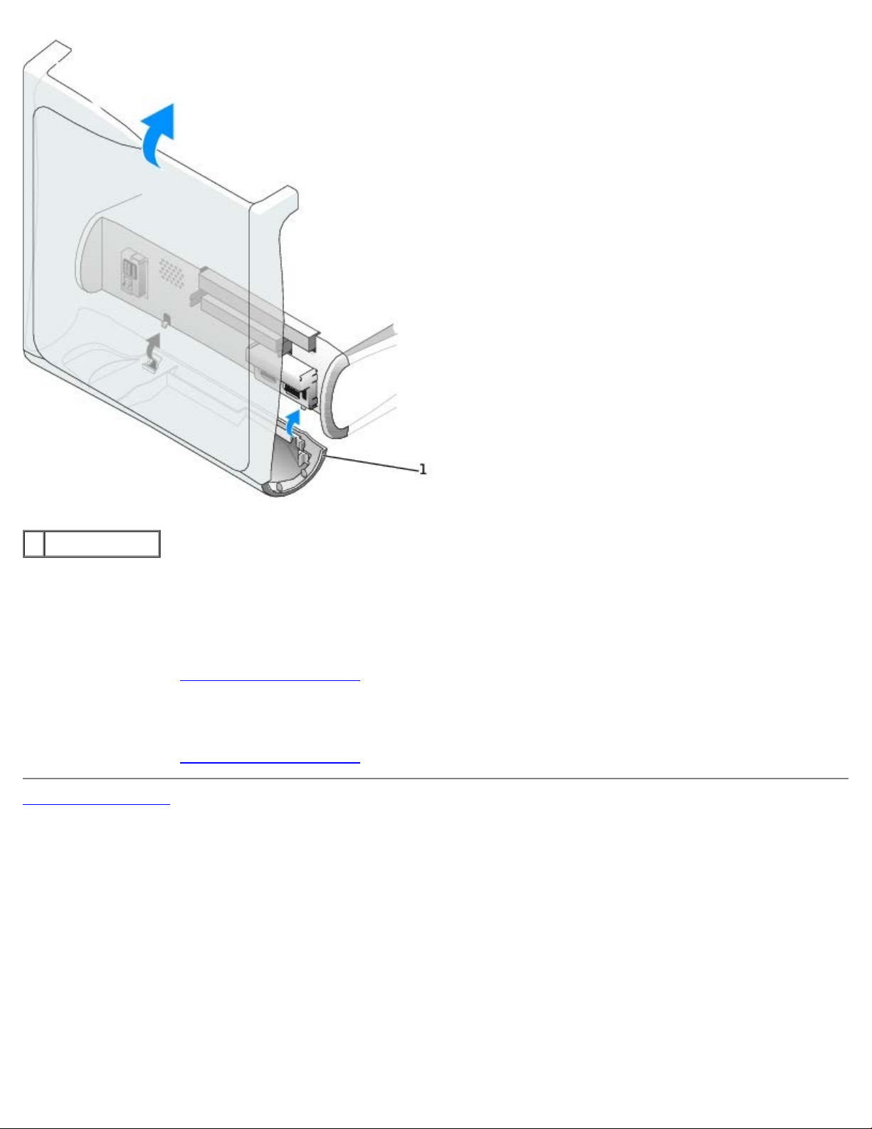
1. Open the cover to a 90-degree angle and release the insert tabs from inside the computer.
Releasing the Insert Tabs
Page 58

2. Press the insert until it pops free of the front-panel cover.
Removing the Front-Panel Inserts
Floppy Drive
CAUTION: Before you perform this procedure, see "Precautionary Measures."
Removing a Floppy Drive
Page 59

1. Disconnect the power and floppy-drive cables from the back of the floppy drive.
2. Disconnect the other end of the floppy-drive cable from the system board (labeled DSKT).
Removing Power and Drive Cables
1 power cable
2 floppy-drive cable
3 floppy-drive connector (DSKT)
3. Press inward on the two tabs on the sides of the drive, slide the drive upward, and remove it from the floppy-drive
bay.
Page 60

Installing a Floppy Drive
1. If the replacement drive does not have the bracket rails attached, see step 2 in the previous section for instructions on
attaching rails.
2. Gently slide the drive into place until the tabs securely click into position.
3. Attach the power and floppy-drive cables to the floppy drive.
4. Connect the other end of the floppy-drive cable to the connector labeled DSKT on the system board.
Attaching Power and Drive Cables
1 power cable
2 floppy-drive cable
3 floppy-drive connector (DSKT)
5. If you are installing a new floppy drive rather than replacing a drive, remove the front-panel inserts.
6. Check all cable connections, and fold cables out of the way to provide airflow for the fan and cooling vents.
CD/DVD Drive
CAUTION: Before you perform this procedure, see "Precautionary Measures."
Removing a CD/DVD Drive
1. Disconnect the power, audio, and CD/DVD drive cables from the back of the drive.
Removing Power, Audio, and Drive Cables
Page 61

1 power cable
2 audio cable
3 CD/DVD drive cable
2. Press inward on the two tabs on the sides of the drive, and then slide the drive upward and remove it from the drive
bay.
Installing a CD/DVD Drive
Page 62

1. If you are installing a new drive, unpack the drive and prepare it for installation.
Check the documentation that accompanied the drive to verify that the drive is configured for your computer. If you are
installing an IDE drive, configure the drive for the cable-select setting.
2. Connect the new drive to the set of rails that are attached to the inside of the cover. If a set of rails is not attached
inside the cover, contact Dell.
3. If you are installing a replacement drive, see step 2
4. Gently slide the drive into place until the tabs securely click into position.
5. Connect the power, audio, and CD/DVD drive cables to the drive.
in the previous section for instructions on attaching rails.
Connecting Power, Audio, and Drive Cables
1 power cable
2 audio cable
3 CD/DVD drive cable
6. If you are installing a new CD/DVD drive rather than replacing a drive, remove the front-panel inserts.
7. If you are installing a drive that has its own controller card, install the controller card in a card slot.
8. Check all cable connections, and fold cables out of the way to provide airflow for the fan and cooling vents.
Back to Contents Page
Page 63

Back to Contents Page
Front-Panel Inserts
Dell™ OptiPlex™ GX260 Service Manual
Removing Front-Panel Inserts
Replacing Front-Panel Inserts
Removing Front-Panel Inserts
1. On the small form-factor computer, face the front of the computer and use your fingers to remove the front-panel
insert.
2. On the small desktop computer:
a. Face the front of the computer and use your fingers to remove the front-panel insert.
b. Press the insert until it pops free of the front-panel cover.
3. On the small mini-tower computer:
a. Open the computer cover to a 45-degree angle and disconnect the CD/DVD drive data cable.
b. Open the cover to a 90-degree angle and release the insert tabs from inside the chassis.
c. Press the insert until it pops free of the front-panel cover.
Small Form-Factor Computer
Small Desktop Computer
Page 64

Small Mini-Tower Computer
Page 65

Replacing Front-Panel Inserts
To replace a front-panel insert, follow the appropriate procedure, in reverse, in "Removing Front-Panel Inserts."
Back to Contents Page
Page 66

Back to Contents Page
I/O Panel
Dell™ OptiPlex™ GX260 Service Manual
Removing the I/O Panel
Replacing the I/O Panel
Removing the I/O Panel
Small Form-Factor Computer
1. To access the screw that holds the I/O panel to the computer, remove the hard drive.
I/O Panel Removal—Small Form-Factor Computer
1 internal speaker cable
2 chassis intrusion switch cable
3 control-panel cable
4 front audio cable
5 mounting screw
6 I/O cable
2. Disconnect the control-panel cable from the control-panel connector on the I/O panel. Disconnect the I/O cable from
the I/O panel.
3. Remove all cables that are connected to the I/O panel, such as the chassis intrusion switch and internal speaker cables.
Page 67

4. From inside the computer cover, remove the mounting screw that secures the I/O panel to the computer.
5. Remove the I/O panel from the computer.
Small Desktop Computer
1. Remove the hard-drive shroud.
2. Disconnect the hard-drive data cable.
3. Disconnect the control-panel cable from the control-panel connector on the I/O panel. Disconnect the I/O cable from
the I/O panel.
Note the routing of the control-panel cable as you remove it from the computer so that you can replace it correctly.
4. Remove all cables that are connected to the I/O panel, such as the chassis intrusion switch and internal speaker cables.
5. Remove the mounting screw that secures the I/O panel to the computer.
6. Remove the I/O panel from the computer.
I/O Panel Removal—Small Desktop Computer
1 I/O cable
2 control-panel cable
3 front audio cable
4 mounting screw
5 chassis intrusion switch cable
6 internal speaker cable
Page 68

7. Remove all cables that are connected to the I/O panel.
8. Remove the mounting screw that secures the I/O panel to the computer.
9. Remove the I/O panel from the computer.
Small Mini-Tower Computer
I/O Panel Removal—Small Mini-Tower Computer
1 internal speaker cable
2 chassis intrusion switch cable
3 mounting screw
4 control-panel cable
5 front audio cable
6 I/O cable
1. Disconnect the control-panel cable from the control-panel connector on the I/O panel. Disconnect the I/O cable from
the I/O panel.
Note the routing of the control-panel cable as you remove it from the computer so that you can replace it correctly.
2. Remove all cables that are connected to the I/O panel, such as the chassis intrusion switch and internal speaker cables.
3. From inside the chassis cover, remove the mounting screw that secures the I/O panel to the chassis.
Page 69

4. Remove the I/O panel from the chassis.
Replacing the I/O Panel
To replace the I/O panel, follow the removal procedures in reverse.
Back to Contents Page
Page 70

Back to Contents Page
Memory
Dell™ OptiPlex™ GX260 Service Manual
Removing a Memory Module
Adding a Memory Module
Removing a Memory Module
CAUTION: Use a wrist grounding strap as explained in "Precautionary Measures."
1. Press the securing clips outward simultaneously until the memory module disengages and pops out slightly from the
socket.
2. Lift the module away from the socket.
Adding a Memory Module
1. Press out the securing clip at each end of the memory module connector.
Installing a Memory Module
1 cutouts (2)
2 connector
3 memory module
Page 71

4 notch
5 securing clips (2)
6 memory connectors on system board
2. Align the notch on the bottom of the module with the crossbar in the connector.
NOTICE: To avoid damage to the memory module, press the module straight down into the socket with equal force
applied at each end of the module.
3. Insert the module straight down into the connector, ensuring that it fits into the vertical guides at each end of the
connector. Press firmly on the ends of the module until it snaps into place.
If you insert the module correctly, the securing clips snap into the cutouts at each end of the module.
Back to Contents Page
Page 72

Back to Contents Page
Microprocessor
Dell™ OptiPlex™ GX260 Service Manual
Removing and Installing the Heat-Sink Assembly and Microprocessor
Small Form-Factor and Small Desktop Computers
Small Mini-Tower Computer
Small Form-Factor and Small Desktop Computers
1. Disconnect the cooling fan power cable from the FAN connector on the system board.
2. Disconnect the 12-volt power cable from the 12VPOWER connector on the system board.
3. Remove the heat sink/blower assembly.
a. The heat sink is attached to the blower. Press and lower the green lever on the retention mechanism until it is
parallel to the system board.
b. Gently rock the heat sink, and then slightly twist it as you lift it from the microprocessor.
NOTICE: Lay the heat sink down with the thermal solution facing upward.
Heat Sink/Blower Assembly Removal
Page 73

1 blower 4 retention base
2 screws (2) 5 heat sink
3 lever
4. Lift the heat sink/blower assembly away from the microprocessor.
5. Remove the two screws on the blower to remove it from the heat sink.
NOTICE: Do not discard the blower. You will reuse it. If you are installing a microprocessor upgrade kit from Dell,
discard the original heat sink. If you are not installing a microprocessor upgrade kit from Dell, reuse the original heat
sink when you install your new microprocessor.
NOTICE: Be careful not to bend any of the pins when you remove the microprocessor. Bending the pins can
permanently damage the microprocessor.
6. Pull the release lever straight up until the microprocessor is released, and then remove the microprocessor from the
socket.
Microprocessor Removal
1 release lever
2 microprocessor
3 socket
NOTICE: Ground yourself by touching an unpainted metal surface on the back of the computer.
NOTICE: Be careful not to bend any of the pins when you unpack the microprocessor. Bending the pins can
permanently damage the microprocessor.
7. Unpack the new microprocessor.
Microprocessor Installation
Page 74

1 pin-1 corners of microprocessor and socket aligned
NOTICE: You must position the microprocessor correctly in the socket to avoid permanent damage to the
microprocessor and the computer when you turn on the computer.
8. If the release lever on the socket is not fully extended, move it to that position.
9. Align the pin-1 corners of the microprocessor and socket.
NOTICE: When you place the microprocessor in the socket, ensure that all of the pins fit into the corresponding holes
on the socket. Be careful not to bend the pins.
10. Set the microprocessor lightly in the socket and make sure that all pins are headed into the correct holes. Do not use
force, which could bend the pins if the microprocessor is misaligned. When the microprocessor is positioned correctly,
press it with minimal pressure to seat it.
11. When the microprocessor is fully seated in the socket, pivot the release lever back toward the socket until it snaps into
place to secure the microprocessor.
NOTICE: Ground yourself by touching an unpainted metal surface on the back of the computer.
NOTICE: If you are not installing a microprocessor upgrade kit from Dell, reuse the original blower/heat-sink assembly
when you replace the microprocessor.
If you are installing a microprocessor replacement kit from Dell, return the microprocessor to Dell in the same package
in which your replacement kit was sent.
12. Reinstall the two screws that attach the blower to the heat sink.
13. Lower the heat sink/blower assembly to the microprocessor so that the heat sink fits in the retention base.
14. Raise the retention lever and press until the heat sink is secured. You will feel the lever pause once it is at a 90-degree
angle. Keep pressing the lever another 30 degrees, ensuring that it is in the locked position.
Heat Sink/Blower Assembly Replacement
Page 75

1 heat sink/blower assembly
2 lever
3 retention base
15. Plug the fan cable into the FAN connector on the system board.
16. Plug the 12-volt power cable into the 12VPOWER connector on the system board.
Small Mini-Tower Computer
1. Disconnect the cooling fan power cable from the FAN connector on the system board.
2. Disconnect the 12-volt power cable from the 12VPOWER connector on the system board.
3. Rotate the airflow shroud.
Airflow Shroud Rotation
Page 76

4. Remove the heat sink.
a. Press and lower the green lever on the retention mechanism until it is parallel to the system board.
b. Gently rock the heat sink, and then slightly twist it as you lift it from the microprocessor.
Heat Sink Removal
Page 77

1 heat sink
2 lever
3 retention base
NOTICE: Lay the heat sink down with the thermal solution facing upward.
NOTICE: If you are installing a microprocessor upgrade kit from Dell, discard the original heat sink. If you are not
installing a microprocessor upgrade kit from Dell, reuse the original heat sink and blower when you install your new
microprocessor.
5. Pull the release lever straight up until the microprocessor is released.
NOTICE: Be careful not to bend any of the pins when you remove the microprocessor from the socket. Bending the
pins can permanently damage the microprocessor.
Microprocessor Removal
Page 78

1 release lever
2 microprocessor
3 socket
6. Remove the microprocessor from the socket.
Leave the release lever extended in the release position so that the socket is ready for the new microprocessor.
NOTICE: You must position the microprocessor correctly in the socket to avoid permanent damage to the
microprocessor and the computer.
7. If the release lever is not extended to the release position, move it to that position.
8. Align pin 1 (the imprinted corner) of the microprocessor and pin 1 of the socket.
Microprocessor Installation
Page 79

1 pin-1 corners of microprocessor and socket aligned
NOTICE: Microprocessor pins are delicate. To avoid damage, ensure that the microprocessor aligns properly with the
socket, and do not use excessive force when you install the processor.
9. Carefully set the microprocessor in the socket and press it down lightly to seat it.
10. Rotate the release lever back toward the system board until it snaps into place, securing the microprocessor.
11. Install the heat sink.
a. Insert the notched end of the heat sink onto the end of the retention base that is opposite the hinge.
b. Lower the heat sink until it fits securely in the base.
12. Raise the retention lever and press until the heat sink is secured. You will feel the lever pause once it is at a 90-degree
angle. Keep pressing the lever another 30 degrees, ensuring that it is in the locked position.
Heat Sink Replacement
1 heat sink
2 lever
3 hinge
4 retention base
5 notch
13. Lower the airflow shroud over the heat sink.
If you installed a microprocessor replacement kit from Dell, return the original heat-sink assembly and microprocessor
to Dell in the same package in which your replacement kit was sent.
14. Reconnect the cooling fan power cable to the FAN connector on the system board.
Page 80

15. Reconnect the 12-volt power cable to the 12VPOWER connector on the system board.
Back to Contents Page
Page 81

Back to Contents Page
Power Supply
Dell™ OptiPlex™ GX260 Service Manual
Removing the Power Supply
Replacing the Power Supply
Removing the Power Supply
Small Form-Factor Computer
1 release button
2 AC power connector
Small Desktop Computer
Page 82

1 release button
board and drives. It is important to route these cables properly when you replace them to prevent them from being
2 AC power connector
Small Mini-Tower Computer
1. Disconnect the AC power cable from the back of the power supply.
2. Disconnect the DC power cables from the system board and the drives.
Note the routing of the DC power cables underneath the clips in the computer as you remove them from the system
Page 83

pinched or crimped.
3. On the small desktop computer, remove the expansion-card cage and remove the power cables from the side of the
hard drive. To remove the power cables, use the cables as leverage and pull away from the clips while simultaneously
pulling on the metal clips with your fingers.
4. On the small mini-tower computer, remove the two screws that attach the power supply to the rear wall.
5. Press the release button. On the small desktop computer, press down on the handle, which in turn presses the release
button.
6. Slide the power supply toward the front of the computer approximately 1 inch.
7. Lift the power supply up and out of the computer.
Replacing the Power Supply
1. Slide the power supply into place.
2. Reconnect the DC power cables.
3. Connect the AC power cable to the connector.
4. On the small desktop computer, reattach the power cables to the side of the hard drive and replace the expansion-card
cage.
5. Run the cables underneath the clips.
6. Press the clips to close them over the cables.
Back to Contents Page
Page 84

Back to Contents Page
5 hard drive connector (IDE1) 16 microprocessor and heat-sink connector (CPU)
System Board
Dell™ OptiPlex™ GX260 Service Manual
System Board Components
Removing the System Board
Replacing the System Board
System Board Components
1 floppy drive connector (DSKT) 12 CD drive audio cable connector (CD_IN)
2 internal speaker (SPEAKER) 13 telephony connector (MODEM)
3 battery socket (BATTERY) 14 power connector (12VPOWER)
4 CD/DVD drive connector (IDE2) 15 second serial connector (SER2)
Page 85

6 front-panel connector (FRONTPANEL) 17 memory module connectors (DIMM A and DIMM B)
7 PCI riser (small mini-tower computer only) 18 microprocessor fan connector (FAN)
8 standby power light (AUX_PWR) 19 power connector (POWER)
9 AGP card connector (AGP) 20 RTC reset jumper (RTCRST)
10 PCI card connectors (PCI1, PCI2, PCI3, and PCI4) 21 password jumper (PSWD)
11 front-panel audio cable connector (FRONTAUDIO)
System Board Jumpers
System-Board Jumper Settings
Jumper Setting Description
PSWD
(green jumper)
RTCRST
jumpered unjumpered
(default)
Password features are enabled.
Password features are disabled.
Real-time clock reset. Can be used for troubleshooting purposes.
Removing the System Board
CAUTION: Before you remove any component from the system board, see "Precautionary Measures."
NOTE: The system board and metal tray are attached and are removed as one piece.
1. Remove any components that restrict access to the system board.
2. Disconnect all cables from the system board.
3. Before you remove the existing system board, visually compare the replacement system board to the existing system
board to make sure that you have the correct part.
4. Pull up on the tab and slide the system board toward the front of the computer, and then lift it up and away.
Page 86

Removing the System Board
5. Place the system board that you just removed next to the replacement system board.
Replacing the System Board
1. Transfer components from the existing system board to the replacement system board.
2. Remove the memory modules and install them on the replacement board.
CAUTION: The microprocessor package and heat-sink assembly can get hot. To avoid burns, be sure that
the package and assembly have had sufficient time to cool before you touch them.
3. Remove the heat-sink assembly and microprocessor
replacement system board.
4. Configure the settings of the replacement system board.
5. Set the jumpers
NOTE: Some components and connectors on the replacement system board may be in different locations than the
corresponding connectors on the existing system board.
on the replacement system board so it is identical to the one on the existing board.
from the existing system board and transfer them to the
6. Orient the replacement board by aligning the notches on the bottom to the tabs on the computer floor.
7. Slide the board toward the back of the computer until it clicks into place.
8. Replace any components and cables that you removed from the system board.
Back to Contents Page
Page 87

Page 88

Back to Contents Page
Small Desktop Computer
Dell™ OptiPlex™ GX260 Service Manual
PCI Cards
Serial Port Adapters
AGP and DVI Adapter Cards
NOTE: Before disconnecting a device from the computer or removing a component from the system board, verify that
the standby power light on the system board is off. For the location of this light, see "System Board
PCI Cards
Removing a PCI Card
CAUTION: Before you perform this procedure, see "Precautionary Measures."
1. Remove the card cage:
a. Check any cables connected to cards through the back-panel openings. Disconnect any cables that will not reach
the card cage once the cage is removed from the computer.
."
b. Gently pull the handle and lift the card cage up and away from the computer.
Removing the Card Cage
1 card cage
2 handle
2. Press the lever on the retention arm and raise the retention arm.
Raising the Retention Arm and Installing a Card
Page 89

1 lever 5 card-edge connector
2 retention arm 6 card connector
3 filler bracket 7 riser board
4 card 8 card cage
Installing a Card
1. If you are installing a new card, remove the filler bracket to create an empty card-slot opening.
If you are replacing a card that is already installed in the computer, remove the card. If necessary, disconnect any
cables connected to the card. Grasp the card by its top corners, and ease it out of its connector.
2. Prepare the card for installation.
CAUTION: Some network adapters automatically start the computer when they are connected to a
network. To guard against electrical shock, be sure to unplug your computer from its electrical outlet
before installing any cards.
3. Insert the card into the card connector.
If the card is full-length, insert the end of the card into the card guide bracket as you lower the card toward its
connector on the system board. Insert the card firmly into the card connector on the riser board.
4. Lower the retention arm and press it into place, securing the card(s) in the computer.
5. Replace the card cage:
a. Align the tabs in the side of the card cage with the slots on the side of the computer, and slide the card cage
down into place.
Page 90

b. Make sure that the riser board is fully seated in the connector on the system board.
Replacing the Card Cage
1 card cage
2 tabs
3 slots
6. Reconnect any cables that you removed in step 1
7. Connect any cables that should be attached to the card.
NOTICE: Do not route card cables over or behind the cards. Cables routed over the cards can prevent the computer
cover from closing properly or cause damage to the equipment.
8. Close the computer cover.
9. Attach the computer stand (optional).
10. Install any drivers required for the card as described in the card documentation.
.
Serial Port Adapters
Installing a Serial Port Adapter
CAUTION: Before you perform this procedure, see "Precautionary Measures."
1. Remove the card cage (see step 1
2. Press the lever on the retention arm and raise the retention arm.
3. Remove the filler bracket.
in "Removing a PCI Card").
Raising the Retention Arm and Installing a Serial Port Adapter
Page 91

1 retention arm
2 filler bracket
3 adapter bracket
4. Slide the adapter bracket down over the card-slot opening, and lower the retention arm, securing the adapter bracket.
5. Route the serial adapter cable under the card cage, and attach the cable to the connector on the system board (labeled
SER2).
Replacing the Card Cage and Connecting the Cable
Page 92

1 card cage
2 serial adapter cable
3 serial adapter system board connector (SER2)
Removing a Serial Port Adapter
CAUTION: Before you perform this procedure, see "Precautionary Measures."
1. Remove the card cage (see step 1
2. Press the lever on the retention arm and raise the retention arm.
3. Lift and remove the adapter bracket.
4. If you are removing the card permanently, install a filler bracket in the empty card-slot opening.
If you need a filler bracket, contact Dell.
NOTE: Installing filler brackets over empty card-slot openings is necessary to maintain FCC certification of the
computer. The brackets also keep dust and dirt out of your computer.
5. Lower the retention arm and press it into place.
in "Removing a PCI Card").
AGP and DVI Adapter Cards
Removing an AGP or DVI Adapter Card
1. Remove the filler bracket by raising the hinged lever and sliding the bracket up.
Press the indented tab on the hinged lever with your thumb until you release the tab. Continue holding the lever and
pull the lever up.
Filler Bracket Removal
Page 93

1 hinged lever
2 indented tab (side view)
2. Press the card-clip lever toward the card slot and remove the installed card.
Removing the Card
1 card notch
2 card-clip lever
3 card-clip tab
4 card clip
5 card slot
Page 94

Installing an AGP or DVI Adapter Card
1. To add or replace the card, press the card-clip lever toward the card slot and gently press the card into the slot
connector until it clicks into place.
2. Release the card-clip lever, ensuring that the tab on the card-clip lever fits into the notch on the front end of the card.
3. Secure the card by lowering the hinged lever on the back panel.
4. Close the computer cover.
5. Attach the computer stand (optional).
NOTICE: To connect a network cable, first plug the cable into the network wall jack, and then plug it into the
computer.
6. Connect the monitor cable to the card's video connector.
7. Connect your computer and devices to electrical outlets, and turn them on.
Back to Contents Page
Page 95

Back to Contents Page
Small Mini-Tower Computer
Dell™ OptiPlex™ GX260 Service Manual
PCI Cards
Serial Port Adapters
AGP and DVI Adapter Cards
NOTE: Before disconnecting a device from the computer or removing a component from the system board, verify that
the standby power light on the system board is off. For the location of this light, see "System Board
PCI Cards
Installing a PCI Card
CAUTION: Before you perform this procedure, see "Precautionary Measures."
1. Press the lever on the card retention arm and raise the retention arm.
."
Raising the Retention Arm and Installing a Card
1 card
2 edge connector
3 card connector
4 retention arm
5 lever
6 filler bracket
Page 96

2. If you are installing a new card, remove the filler bracket to create a card-slot opening, then continue with step 4.
3. If you are replacing a card that is already installed in the computer, remove the card.
If necessary, disconnect any cables connected to the card. Grasp the card by its top corners, and ease it out of its
connector.
4. Prepare the card for installation.
CAUTION: Some network adapters automatically start the computer when they are connected to a
network. To guard against electrical shock, be sure to unplug your computer from its electrical outlet
before installing any cards. Verify that the standby power light on the system board is off. To locate this
light, see "System Board
5. Place the card in the connector and press down firmly. Make sure that the card is fully seated in the slot.
If the card is full-length, insert the end of the card into the card guide bracket as you lower the card toward its
connector on the system board. Insert the card firmly into the card connector on the system board.
."
Card Connection
1 bracket caught outside of slot
2 bracket within slot
3 fully seated card
4 not fully seated card
6. Before you lower the retention arm, ensure that:
The tops of all cards and filler brackets are flush with the alignment bar.
The notch in the top of the card or filler bracket fits around the alignment guide.
Press the arm into place, securing the card(s) in the computer.
Closing the Retention Arm
Page 97

1 filler bracket
2 alignment bar
3 alignment guide
4 retention arm
NOTICE: Do not route card cables over or behind the cards. Cables routed over the cards can prevent the computer
cover from closing properly or cause damage to the equipment.
7. Connect any cables that should be attached to the card.
8. Install any drivers required for the card as described in the card documentation.
Removing a PCI Card
CAUTION: Before you perform this procedure, see "Precautionary Measures."
1. Raise the retention arm (see "Raising the Retention Arm and Installing a Card
2. If necessary, disconnect any cables connected to the card.
3. Grasp the card by its top corners, and ease it out of its connector.
4. If you are removing the card permanently, install a filler bracket in the empty card-slot opening.
If you need a filler bracket, contact Dell.
NOTE: Installing filler brackets over empty card-slot openings is necessary to maintain FCC certification of the
computer. The brackets also keep dust and dirt out of your computer.
5. Lower the retention arm and press it into place, securing the card(s) in the computer.
6. Remove the card's driver from the operating system.
").
Page 98

Serial Port Adapters
Installing a Serial Port Adapter
CAUTION: Before you perform this procedure, see "Precautionary Measures."
1. If you are replacing an adapter, remove the current driver for the card from the operating system.
2. Raise the retention arm.
3. Remove the filler bracket.
4. Slide the card bracket down over the card-slot opening, and lower the retention arm, ensuring that:
The tops of all cards and filler brackets are flush with the alignment bar.
The notch in the top of the card or filler bracket fits around the alignment guide (see "Closing the Retention
Arm").
Press the arm into place, securing the card(s) in the computer.
Raising the Retention Arm and Installing a Card
1 serial port system board connector (SER2)
2 adapter bracket
Page 99

3 serial adapter cable
4 retention arm
5. Attach the serial adapter cable to the serial port connector on the system board (labeled SER2).
AGP and DVI Adapter Cards
Removing an AGP or DVI Adapter Card
1. Remove the filler bracket by raising the hinged lever and sliding the bracket up.
AGP Slot Filler Bracket Removal
1 hinged lever
2 filler bracket
2. On the card clip, press the card-clip lever toward the card slot.
3. Pull the card up and out of the card clip.
AGP Card Removal
Page 100

1 card-clip lever 3 slot connector
2 card clip 4 card slot
Installing an AGP/DVI Adapter Card
1. To add or replace the card, gently press it down into the slot connector until it clicks into place.
2. Release the card-clip lever, ensuring that the tab on the card-clip lever fits into the notch on the front end of the card.
3. Secure the card by lowering the hinged lever on the back panel.
4. Close the computer cover.
NOTICE: To connect a network cable, first plug the cable into the network wall jack, and then plug it into the
computer.
5. Connect the monitor cable to the card's video connector.
6. Connect your computer and devices to electrical outlets, and turn them on.
Back to Contents Page
 Loading...