

Page 1

Dell™OptiPlex™GX200ServiceManual
Small Form-Factor Chassis — Removing and Replacing Parts
Low-Profile Chassis — Removing and Replacing Parts
Midsize Chassis — Removing and Replacing Parts
Mini Tower Chassis — Removing and Replacing Parts
Notes, Notices, and Cautions
Throughout this guide, blocks of text may be accompanied by an icon and printed in bold type or in italic type. These blocks are notes, notices,
and cautions, and they are used as follows:
Information in this document is subject to change without notice.
©2000 Dell Computer Corporation. All rights reserved.
Reproduction in any manner whatsoever without the written permission of Dell Computer Corporation is strictly forbidden.
Trademarks used in this text: Dell and OptiPlex are trademarks of Dell Computer Corporation.
Other trademarks and trade names may be used in this document to refer to either the entities claiming the marks and names or their products. Dell Computer Corporation
disclaims any proprietary interest in trademarks and trade names other than its own.
Initial release: 18 April 2000
Last revised: 31 Jul 2000
NOTE: A NOTE indicates important information that helps you make better use of your system.
NOTICE: A NOTICE indicates either potential damage to hardware or loss of data and tells you how to avoid the problem.
CAUTION: A CAUTION indicates a potentially hazardous situation which, if not avoided, may result in minor or moderate
injury.
Page 2
Back to Contents Page
Low-Profile Chassis — RemovingandReplacingParts:Dell™OptiPlex™GX200
Systems Service Manual
Overview
This section provides procedures for removing and replacing the components, assemblies, and subassemblies in the Dell OptiPlex low-profile
chassis GX200 system.
Unless otherwise noted, each procedure assumes that the following conditions exist:
l You have performed the steps in "Precautionary Measures."
l You have removed the computer cover.
l You can replace or reinstall a part by performing the removal procedure in reverse order unless additional information is provided.
Recommended Tools
Most of the procedures in this file require the use of one or more of the following tools:
l Small flat-blade screwdriver
l Wide flat-blade screwdriver
l #1 and #2 Phillips-head screwdrivers
l 1/4-inch nut driver
Also, use a wrist grounding strap as explained in "Precautionary Measures."
Precautionary Measures
Before you perform any procedure in this section, take a few moments to read the following caution for your personal safety and to prevent
damage to the system from electrostatic discharge (ESD).
Overview
System Power Supply
Recommended Tools
Expansion-Card Cage
Precautionary Measures
Riser Boards
Internal Views
System Board Components
Computer Cover
Expansion Cards
Eject, Power, and Reset Buttons
Memory
Front-Panel Inserts
Microprocessor/Cooling Fan/Heat Sink Assembly
Control Panel
System Battery
Chassis Intrusion Switch
System Board
Drives
CAUTION: FOR YOUR PERSONAL SAFETY AND PROTECTION OF THE EQUIPMENT
Before you start to work on the system, perform the following steps in the sequence listed:
1. Turn off the computer and all peripherals.
2. Disconnect the computer and peripherals from their electrical outlets. Also, disconnect any telephone or telecommunication lines from
the computer. Doing so reduces the potential for personal injury or shock.
3. If you are disconnecting a peripheral from the computer or are removing a component from the system board, wait 10 to 20 seconds
after disconnecting the computer from the electrical outlet before disconnecting the peripheral or removing the component to avoid
Page 3
Internal Views
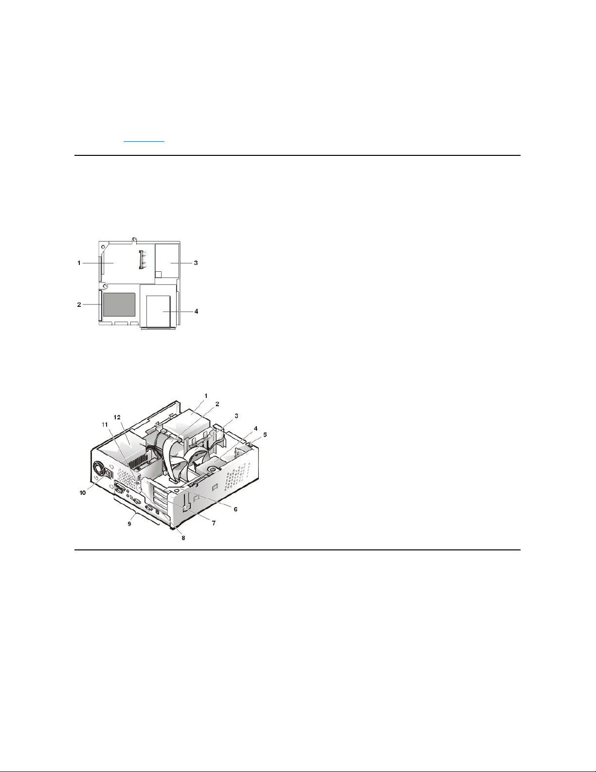
Figure 1 shows a top view of the low-profile chassis to help you orient yourself when you work inside the computer.
Figure 1. Low-Profile Chassis Orientation View
Figure 2 shows the low-profile chassis with the cover removed.
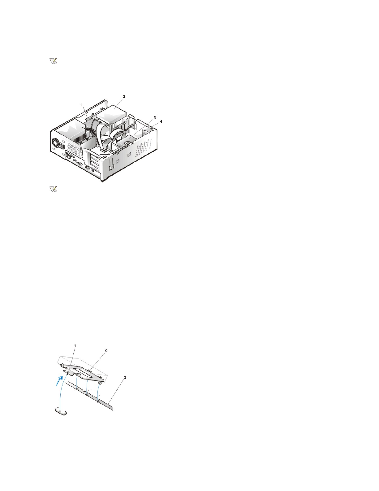
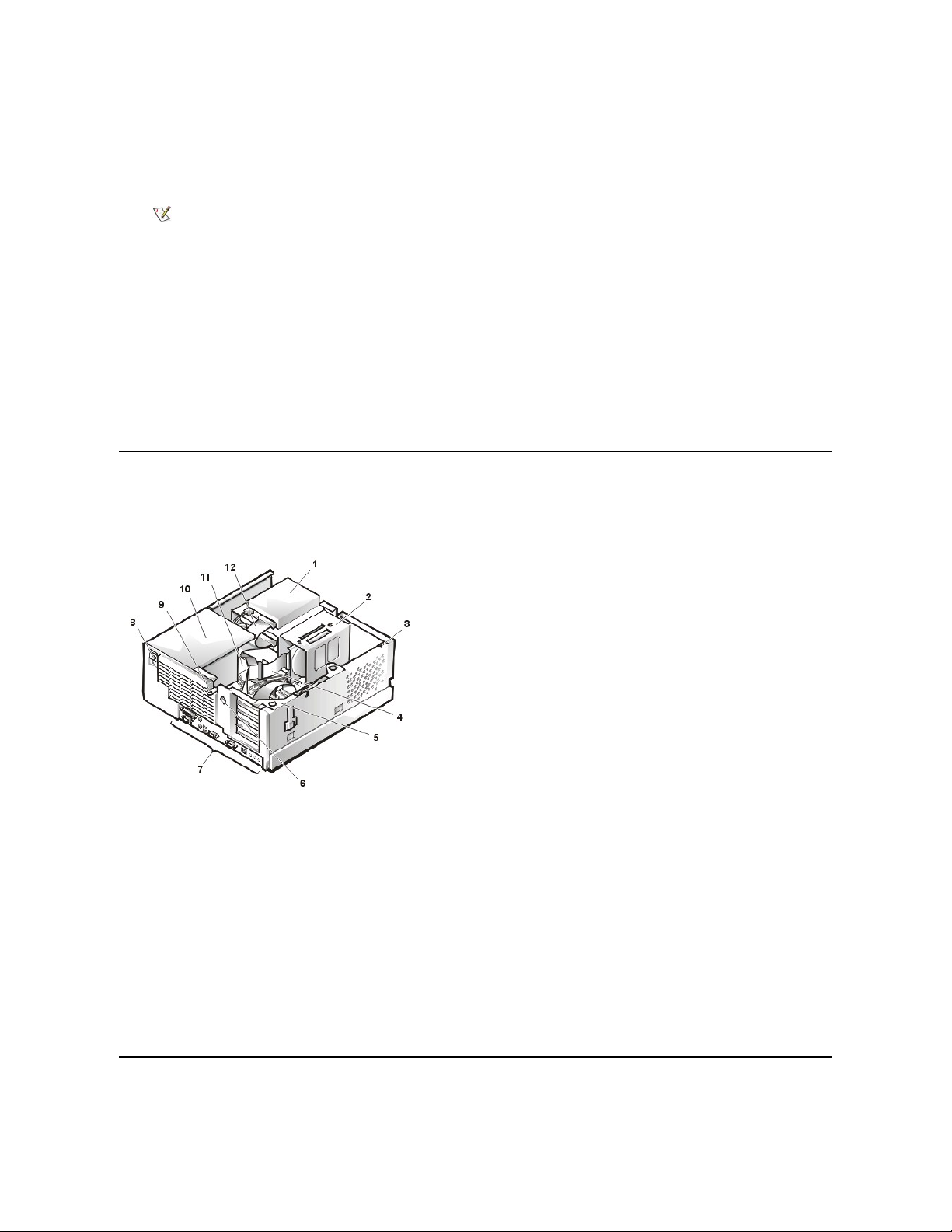
Figure 2. Inside the Low-Profile Chassis
Computer Cover
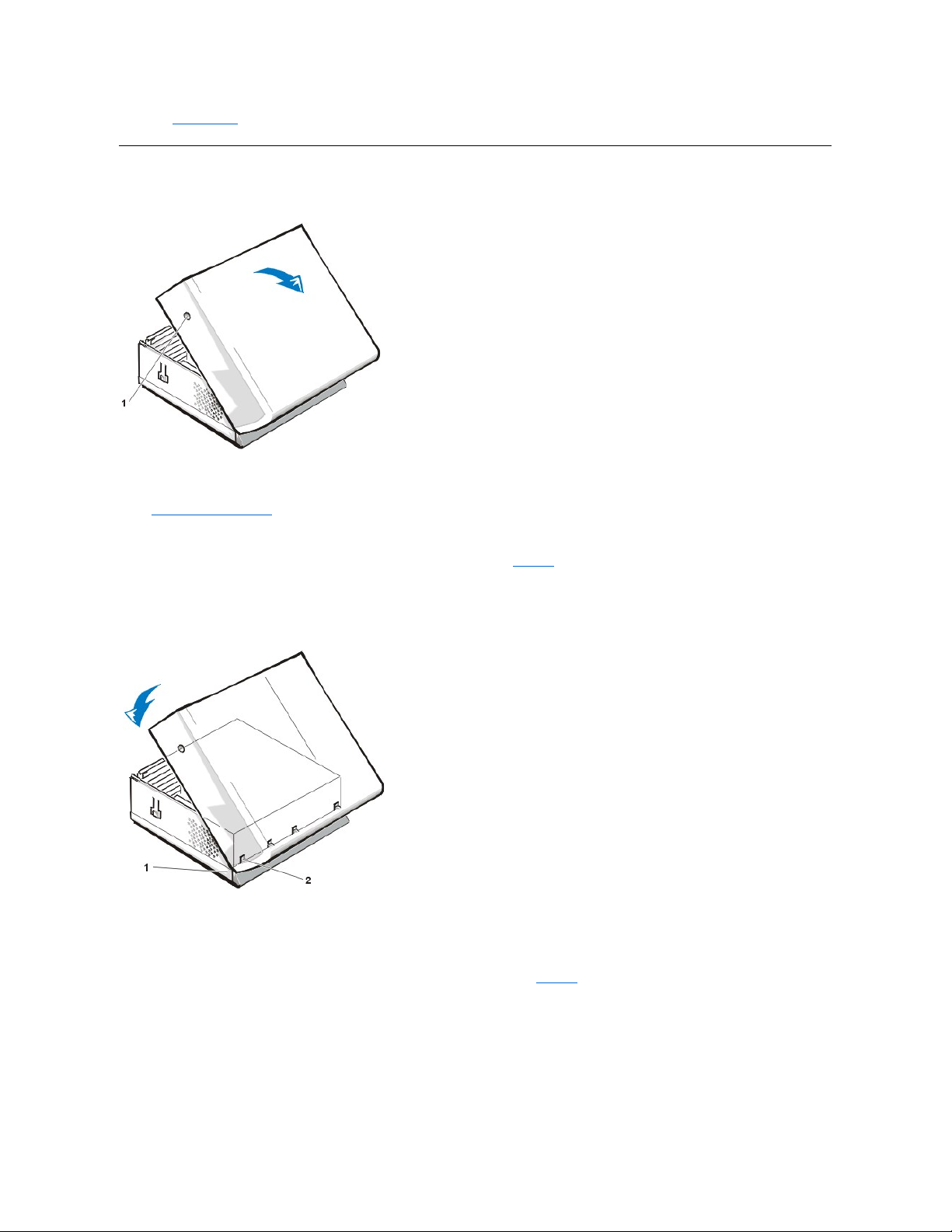
Figure 3. Computer Cover Removal
possible damage to the system board.
4. Wear a wrist grounding strap, and clip it to an unpainted metal surface, such as the padlock loop on the back of the chassis. If a wrist
grounding strap is not available, touch any unpainted metal surface on the back of the computer or on the computer chassis, such as
thepowersupply,todischargeanystaticchargefromyourbodybeforetouchinganythinginsidethecomputer.Whileyouwork,
periodically touch an unpainted metal surface on the computer chassis to dissipate any static electricity that might harm internal
components. Also avoid touching components or contacts on a card and avoid touching pins on a chip.
5. Verify that the auxiliary power indicator on the riser board is not on. If it is on, you may need to wait 10 to 30 seconds for it to go out
(see Riser Boards).
1
System board
2
Hard-disk drive
3
Power supply
4
Externally accessible drive bays
1
Diskette drive in upper bay
2
Diskette drive interface cable
3
Hard-disk drive interface cable
4
Hard-disk drive
5
Chassis intrusion switch
6
Expansion-card cage
7
Expansion-card slots
8
Security cable slot
9
I/O ports and connectors
10
AC power receptacle
11
Padlock ring
12
Power supply
Page 4
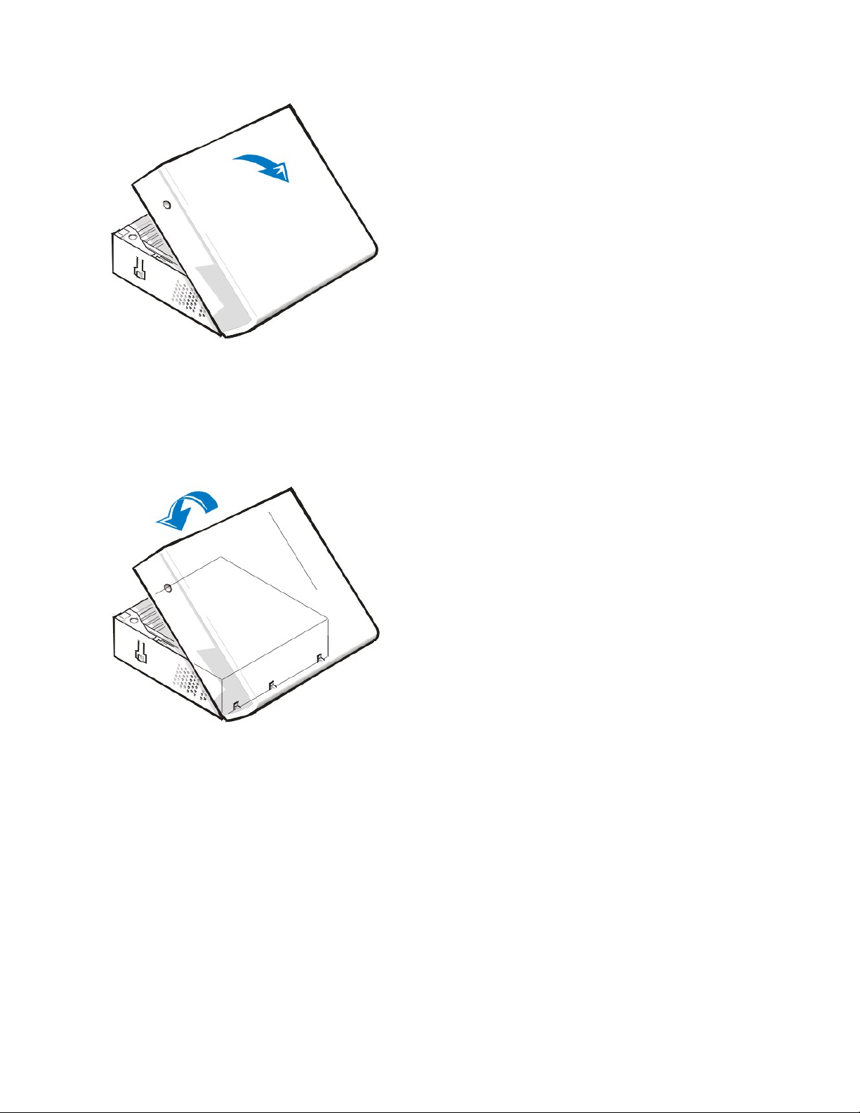
To remove the low-profile chassis computer cover, perform the following steps:
1. Press in on the two securing buttons until the cover is free to swing up (see Figure 3).
2. Raisethebackofthecover,andpivotittowardthefrontofthecomputer.
3. Lift the cover off the hooks at the front of the chassis.
4. Disengage the tabs that secure the cover to the top of the chassis, and lift the cover away.
Figure 4. Computer Cover Replacement
To replace the low-profile chassis computer cover, perform the following steps:
1. Face the front of the computer and hold the cover at a slight angle (see Figure 4).
2. Align the bottom of the cover with the bottom of the chassis and insert the hooks on the cover into the recessed slots on the computer
chassis so that the tabs catch the hooks inside the slots.
3. Pivot the cover down toward the back of the chassis and into position.
Make sure that the securing buttons click into place.
To reset the chassis intrusion detector, perform the following steps:
1. Reconnect all cables to their connectors at the back of the computer.
2. Restart the system.
3. Enter System Setup. To do this, press <F2> when F2=Setup appears in the upper-right corner of the screen.
If the operating system begins to load into memory, allow the system to complete the load operation, shut down the system, and try again.
4. Restore the system configuration settings.
Page 5

5. While in System Setup, perform the following steps to configure the system if it has an LS-120 SuperDisk drive:
a. Set Diskette Drive A and Diskette Drive B to Not Installed.
b. Set Secondary Drive 0 or Secondary Drive 1, as appropriate, to Auto.
c. Go to the second page and set Diskette to Off.
6. While in System Setup, reset the chassis intrusion detector under the System Security tab by changing Chassis Intrusion to Enabled,
Enabled-Silent, or Disabled.
7. If no other changes are required in System Setup, press <Esc> and follow the menu directions to restart the system and implement the
changes.
8. Run the Dell Diagnostics to verify that the system is operating correctly.
Eject, Power, and Reset Buttons
Figure 5. Eject, Power, and Reset Button Removal
To remove the eject, power, and reset buttons, perform the following steps:
1. Lay the computer cover on a flat work surface, with the inside of the top cover facing up.
2. To remove the 3.5-inch diskette-drive eject button, pull gently on the plastic part of the button until it comes free.
3. To remove the power button or the reset button, use a small screwdriver and push in the two or three plastic clips that hold the button to the
bezel.Whentheseclipsarereleased,thebuttonscomefreefromthebezel.
Front-Panel Inserts
Figure6.5.25-Inch Front-Panel Insert Removal
To remove a 5.25-inch front-panel insert, perform the following steps:
1. Hold the bezel with the front facing you.
2. From the front of the top cover, use your thumbs to press inward on the insert until it snaps free of the cover.
To replace a 5.25-inch front-panel insert, position the two ring-tabs over the posts on the inside of the bay opening, and then press the ring tabs
over the posts.
NOTE: If the system does not have an audio expansion card but does have an integrated audio controller, be sure that the
Sound setting is On. If the system has an audio expansion card, be sure that the Sound setting is Off.
1
Disk eject button
2
Reset button
3
Power button
1
Posts (2)
2
Front of top cover
3
Ring tabs (2)
Page 6
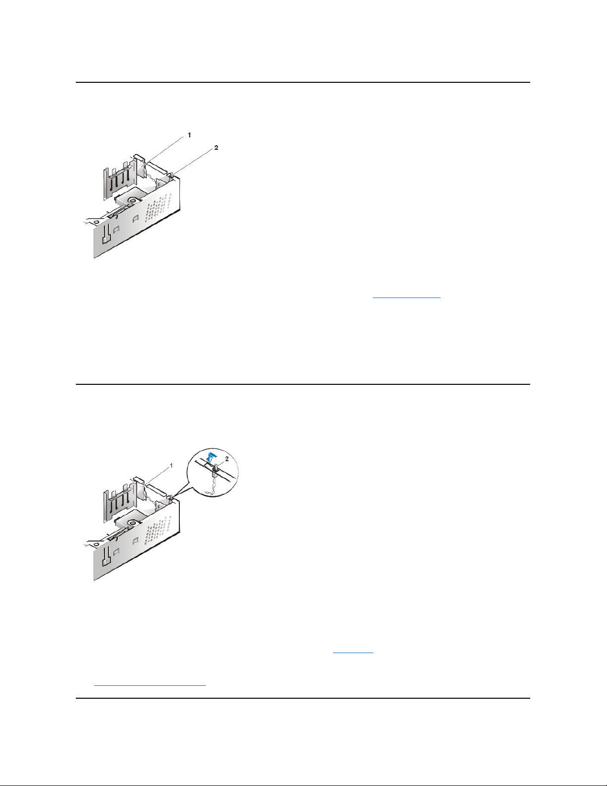
Control Panel
Figure 7. Control Panel Removal
To remove the control panel in the low-profile chassis, perform the following steps:
1. Disconnect the control panel cable from the PANEL connector on the system board (see "System Board Labels" for the location of the
PANEL connector).
2. From inside the chassis, remove the mounting screw that secures the control panel to the chassis.
3. Disconnect the chassis intrusion switch cable connector from the control panel.
4. Remove the control panel from the chassis.
When you reinstall the control panel, be sure to put the right side of the control panel behind the mounting tab.
Chassis Intrusion Switch
Figure 8. Chassis Intrusion Switch Removal
To remove the chassis intrusion switch in the low-profile chassis, perform the following steps:
1. Disconnect the chassis intrusion switch cable connector from the control panel on the front of the chassis as shown in Figure 8.
Note the routing of the chassis intrusion cable as you remove it from the chassis. Hooks on the chassis keep the cable in place.
2. Slide the chassis intrusion switch out of its slot to remove it from the chassis (see Figure 8).
3. Install the replacement chassis intrusion switch and cable.
4. Reset the chassis intrusion detector.
1
Control panel
2
Chassis intrusion switch
1
Control panel
2
Chassis intrusion switch
Page 7
Drives
Figure 9. Drive Locations
3.5-Inch Diskette Drive
To remove the 3.5-inch diskette drive assembly from the drive shelf, perform the following steps:
1. Disconnect the DC power cable and the interface cable from the back of the drive.
2. Press both release latches on the left side of the 3.5-inch diskette drive.
3. Pivot the 3.5-inch diskette drive upward 1 inch (2.5 cm), and then pull the drive away from the notched tabs on the right chassis wall.
4. Remove the bracket from the diskette drive you just removed.
5.25-inch Drive
To remove the 5.25-inch drive/bracket assembly (the 5.25 drive is usually a CD-ROM drive), perform the following steps:
1. Remove the diskette drive and bracket.
2. Disconnect the DC power cable and EIDE cable from the drive.
3. Lift the 5.25-inch drive/bracket straight up and out of the chassis.
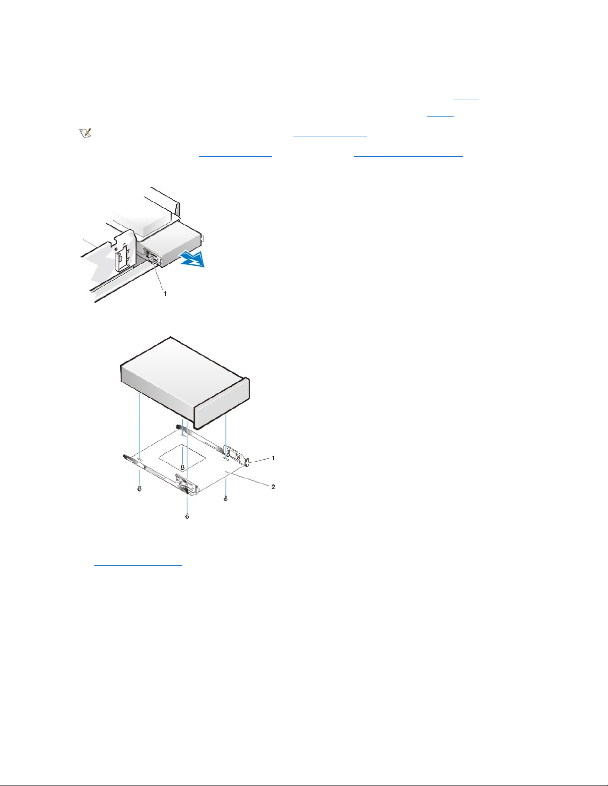
Hard-Disk Drive Removal
Figure 10. Hard-Disk Drive/Bracket Assembly Removal
To remove the hard-disk drive/bracket assembly, perform the following steps:
1. Disconnect the DC power cable and EIDE cable from the drive.
NOTE: In all of the following procedures, left and right refer to your left and right as you face the front of the computer.
1
5.25-inchdrive
2
3.5-inch diskette drive
3
Hard-disk drive
4
Chassis intrusion switch
NOTE: Computer configurations differ. Your computer may have an Iomega Zip drive installed instead of a 3.5-inch diskette drive, or
your computer may have no externally accessible drives installed.
1
Captive screw
2
Hinge tabs on back of drive bracket (2)
3
Slots in floor divider (3)
Page 8
2. Loosen the captive screw securing the hard-disk drive/bracket to the bottom of the chassis.
3. Grasp the drive/bracket, and pivot it upward from the chassis until the two hinge tabs (located on the side opposite the screw) clear the floor
divider (see Figure 10). Then lift the bracket upward and out of the chassis.
4. To remove the hard-disk drive from the bracket, place the drive/bracket on a flat surface with the bracket facing up.
5. Remove the four screws that secure the bracket to the drive.
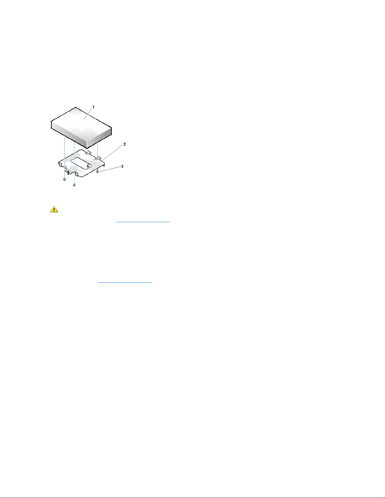
Figure 11. Hard-Disk Drive to Bracket Installation
To install a replacement hard-disk drive,performthefollowingsteps.
NOTICE: To avoid damaging the drive by ESD, ground yourself by touching an unpainted metal surface on the back of the computer.
NOTICE: When you unpack the drive, do not set it on a hard surface, which may damage the drive. Instead, set the drive on a
surface, such as a foam pad, that will sufficiently cushion it.
1. Prepare the drive for installation.
Check the documentation for the drive to verify that it is configured for your computer system.
2. If not already done, remove the computer cover.
3. To install the hard-disk drive to the bracket, place the drive top-down on a flat surface with the bracket mounting holes facing up.
4. Position the bracket over the holes and install four screws to secure the bracket to the drive.
5. Insert the bracket's hinge tabs into the chassis slots so that the tabs hook over the slots.
6. Rotate the bracket toward the chassis floor and secure the bracket with a screw.
7. Connect a power cable to the power input connector on the back of the drive (see Figure 12).
8. Check all connectors to ensure that they are properly cabled and firmly seated.
9. Connect one of the device connectors on the EIDE cable to the 40-pin interface connector on the back of the hard-disk drive.
NOTICE: You must match the red colored stripe on the EIDE cable with pin 1 on the drive's interface connector to avoid possible
damage to your system.
Figure 12. Hard-Disk Drive Cable Attachment
1
Hard-disk drive
2
Bracket
3
Screws (4)
CAUTION: To avoid the possibility of electric shock, turn off the computer and any peripherals, disconnect them from
electrical outlets, and then wait at least 5 seconds before you remove the computer cover. Also, before you install a drive, see
the other precautions in "Precautionary Measures."
Page 9
NOTICE: You must attach the blue connector on the EIDE interface cable to the IDE1 connector on the system board to avoid
possible damage to your system.
10. If it is not already connected, connect the blue connector on the EIDE interface cable to the IDE1 connector on the system board.
To locate the IDE1 connector on the system board, see "System Board Components."
11. Replace the computer cover.
12. Reset the chassis intrusion detector. While in System Setup, update the appropriate Primary Drive option, 0 or 1 (see the online System
User's Guide for complete information).
13. Partition and logically format your drive before you proceed to the next step.
See the documentation for your operating system for instructions.
14. If the drive you just installed is the primary drive, install your operating system on the hard-disk drive.
For instructions, refer to the documentation that came with your operating system.
System Power Supply
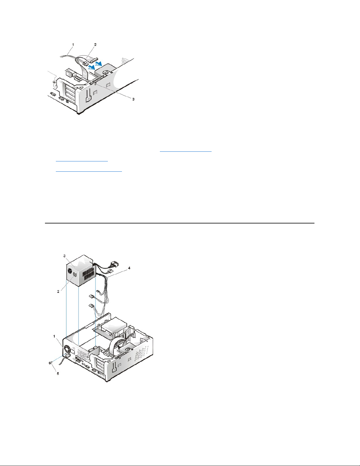
Figure 13. Power Supply Removal
To remove the system power supply, perform the following steps:
1. Disconnect the AC power cable from the back of the power supply.
2. DisconnecttheDCpowercablesfromthesystemboardandthedrives.
1
Power cable
2
EIDE interface cable
3
IDE1 connector on system board
1
AC power cord
2
AC power receptacle
3
Power supply
4
DC power cables
5
Securing screw
Page 10
Note the routing of the DC power cables underneath the tabs in the chassis as you remove them from the system board and drives. It is
important to route these cables properly when you replace them to prevent them from being pinched or crimped.
3. Removethescrewbelowthefanguardonthebackofthechassis.
4. Slide the power supply toward the front of the computer approximately 1 inch.
5. Liftthepowersupplyupandoutofthechassis.
Expansion-Card Cage
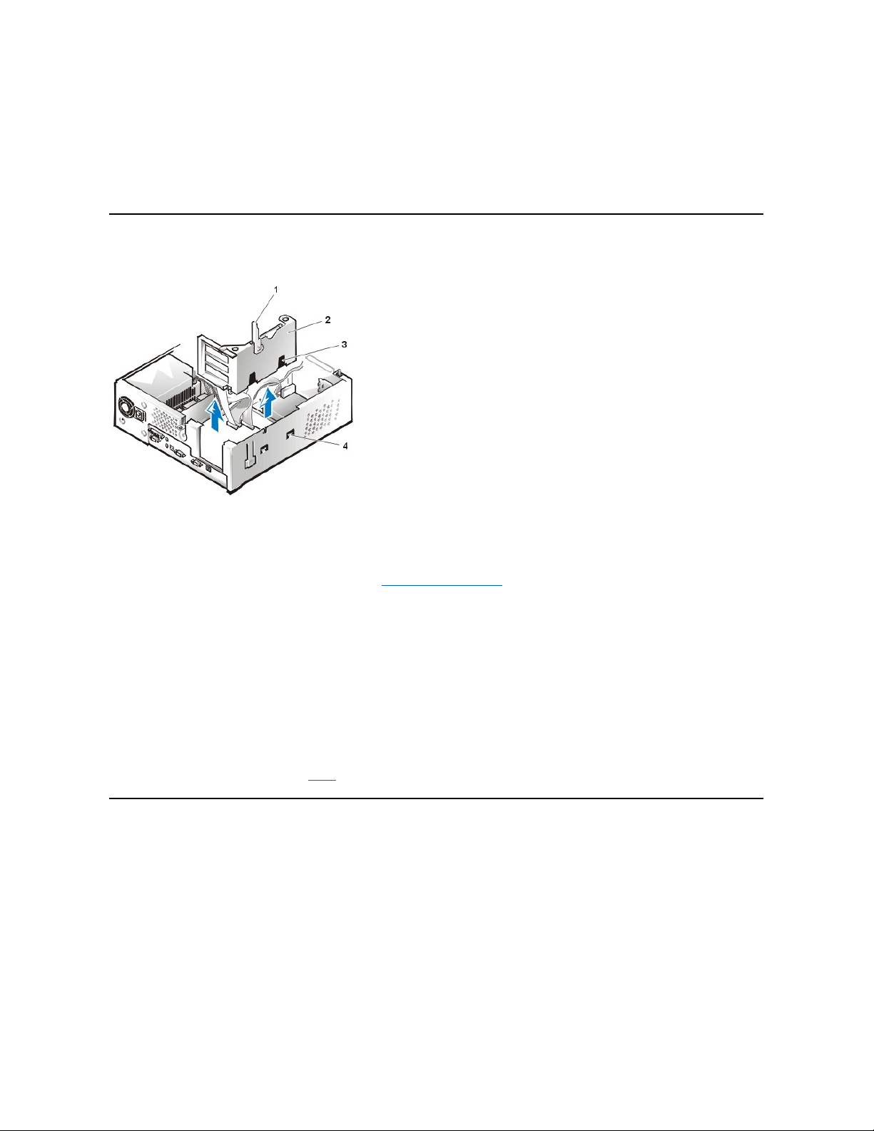
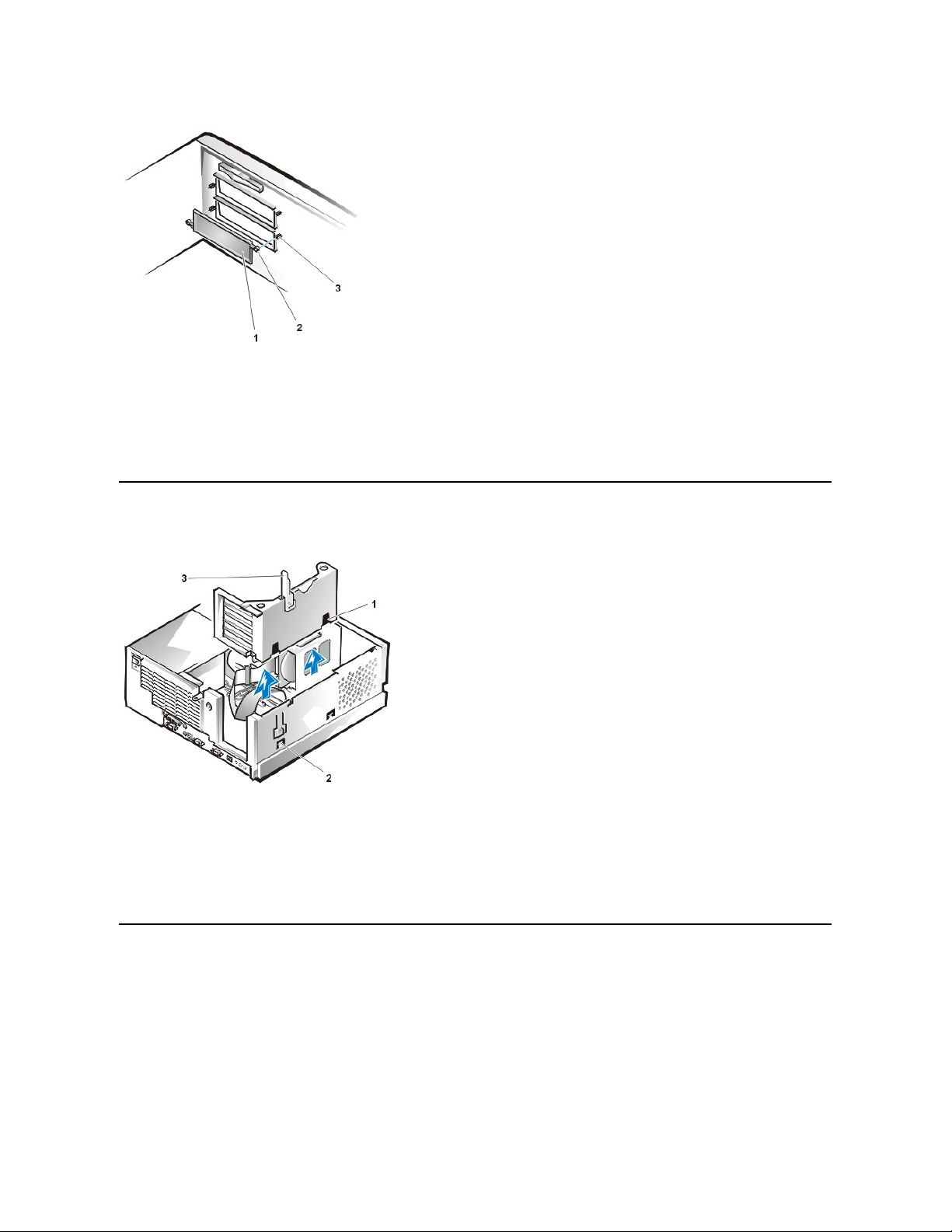
Figure 14. Expansion-Card Cage Removal
To remove the expansion-card cage, perform the following steps:
1. Examine any cables connected to expansion cards through the back-panel openings and disconnect any cables that will not reach to where
the cage must be placed upon removal from the chassis.
2. Locatethesecuringlever(seeFigure14).Rotatetheleverupwarduntilitstopsinanuprightposition.
3. Slide the expansion-card cage out of the chassis.
4. Lift the expansion-card cage up and away from the chassis.
To replace the expansion-card cage into the low-profile chassis, perform the following steps:
1. With the securing lever in the upright position, align the expansion-card cage slots with the tabs in the chassis opening for the expansioncard cage (see Figure 14). Slide the expansion-card cage into place.
2. Rotate the securing lever downward until it is flush with the top of the chassis. Make sure that the riser board is fully seated in the RISER
connector on the system board.
3. Reconnect any cables you removed in step 1 of the previous procedure.
Riser Boards
The low-profile chassis has a standard PCI riser board (see Figure 15) or an optional PCI/ISA riser board (see Figure 16). The PCI riser board
provides three PCI expansion-card slots. The PCI/ISA riser board provides one PCI expansion-card slot, one ISA expansion-card slot, and one
shared PCI/ISA expansion-card slot.
Figure 15. PCI Riser Board (Standard)
1
Securing lever
2
Expansion-card cage
3
Slots (2)
4
Tabs (2)
NOTICE: Use a wrist grounding strap as explained in "Precautionary Measures."
Page 11
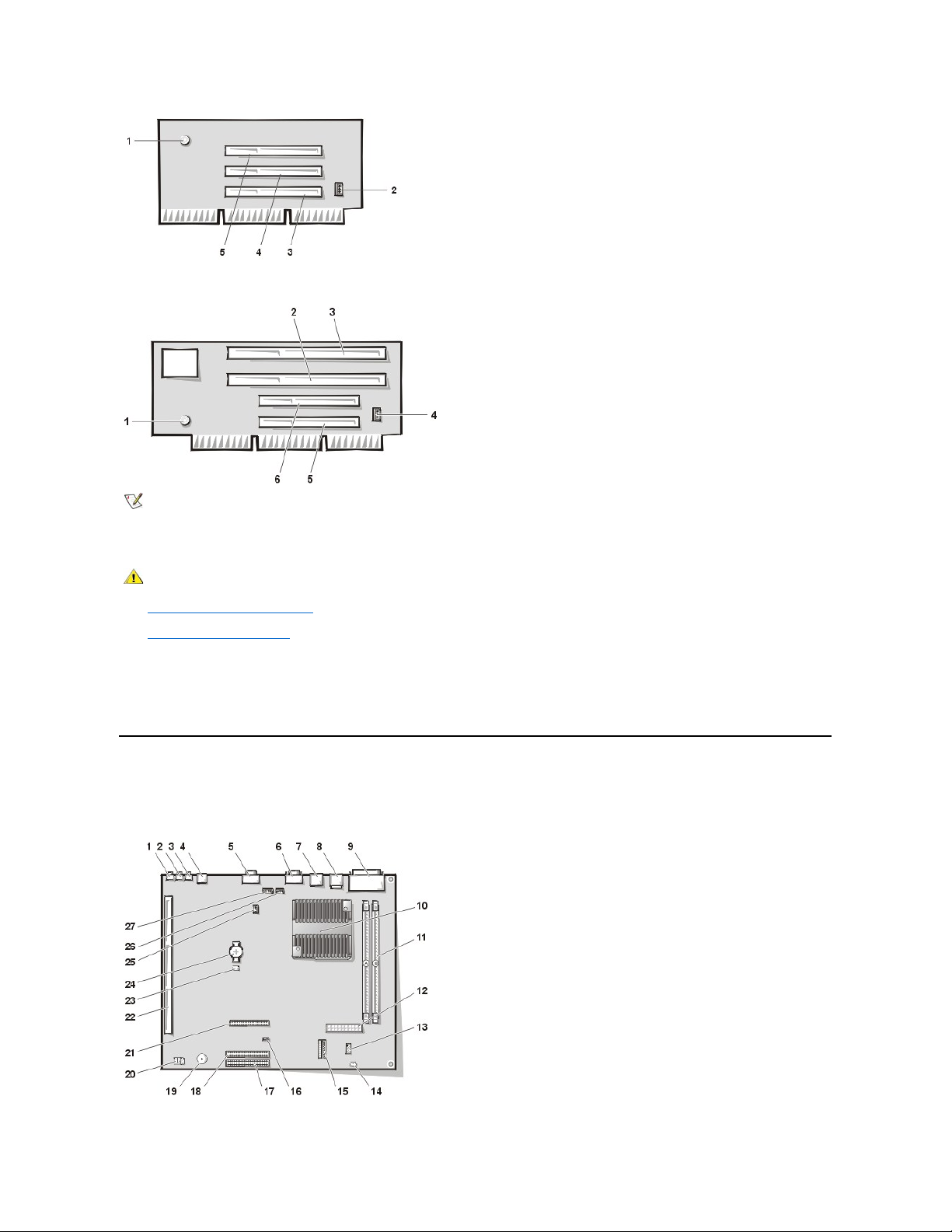
Figure 16. PCI/ISA Riser Board (Optional)
To remove the riser board, perform the following steps.
1. Remove the expansion-card cage.
2. Remove the expansion cards installed in the slots.
3. Remove the screws securing the riser board to the expansion-card cage.
4. Lift the riser board off the expansion-card cage.
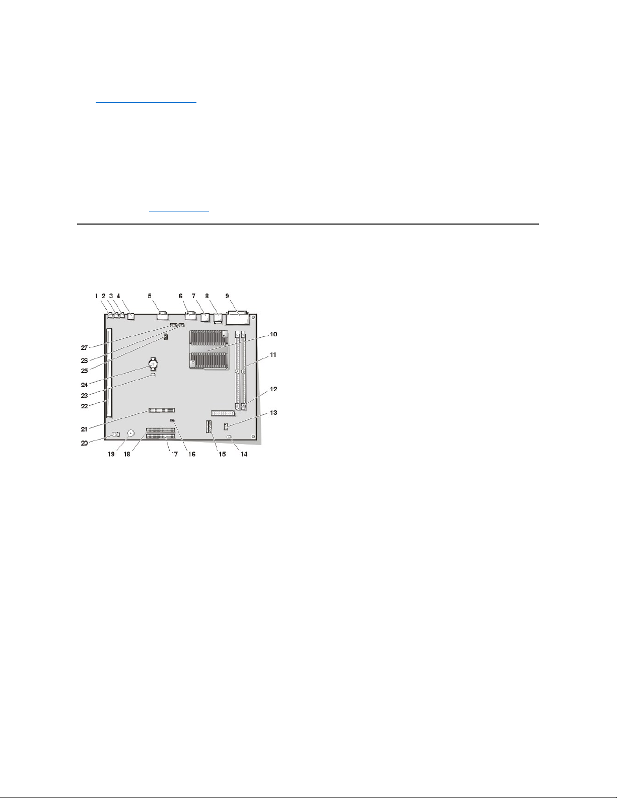
System Board Components
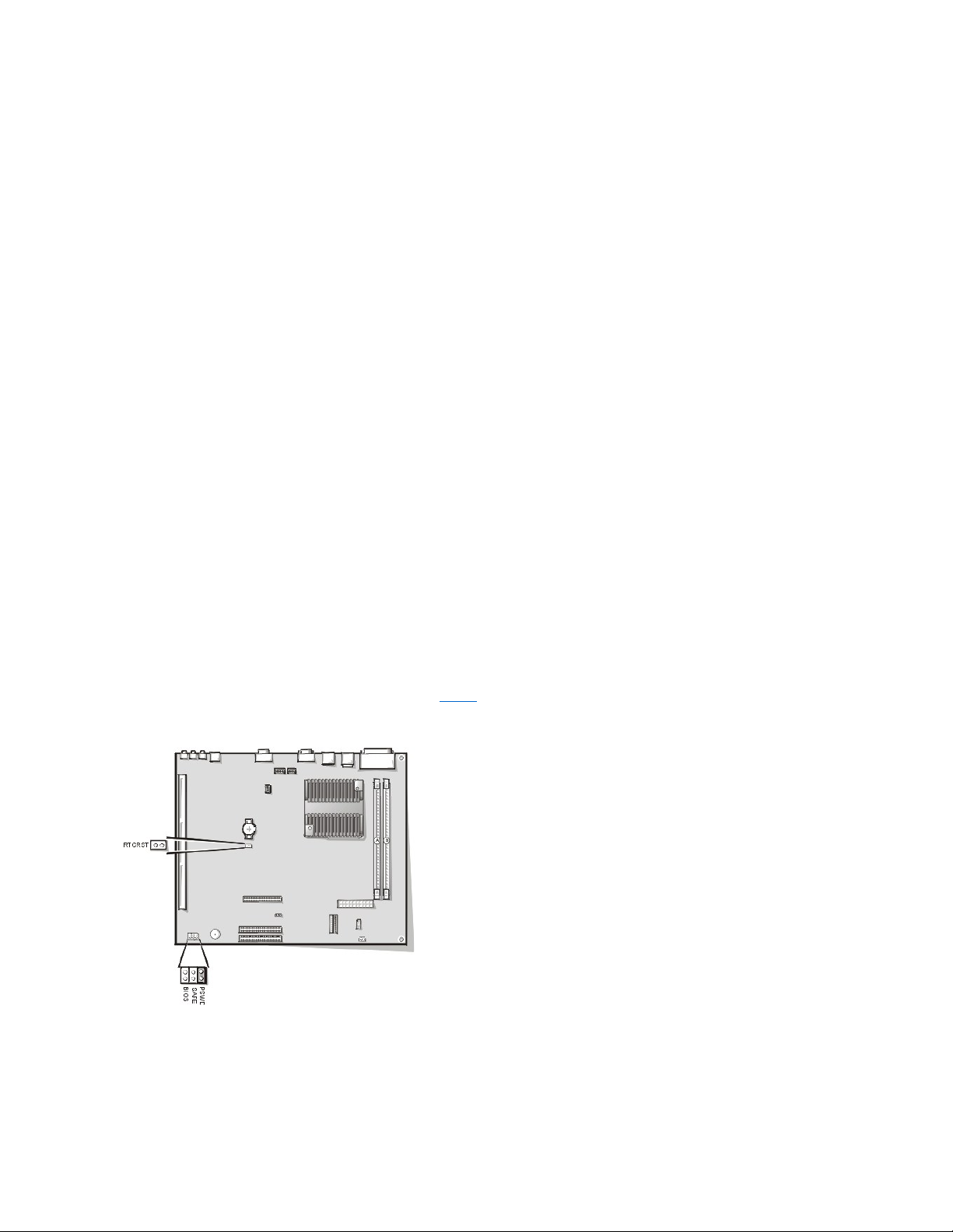
Figure 17 shows the system board and the location of all its sockets and connectors.
Figure 17. System Board Components
1
Auxiliary power indicator LED (AUX_LED)
2
Wakeup On LAN (WOL) connector
3
PCI expansion slot 1 (PCI1)
4
PCI expansion slot 2 (PCI2)
5
PCI expansion slot 3 (PCI3)
1
Auxiliary power LED (AUX_LED)
2
ISA expansion-card connector 1 (ISA1)
3
ISA expansion-card connector 2 (ISA2)
4
Remote Wakeup header (WOL)
5
PCI expansion-card connector 1 (PCI1)
6
PCI expansion-card connector 2 (PCI2)
NOTE: The ISA expansion-card connector 1 and PCI expansion-card connector 2 share an expansion slot; only one of these two
connectors can be used at any given time.
CAUTION: Ground yourself by touching an unpainted metal surface on the back of the computer.
1
Line-in connector
Page 12
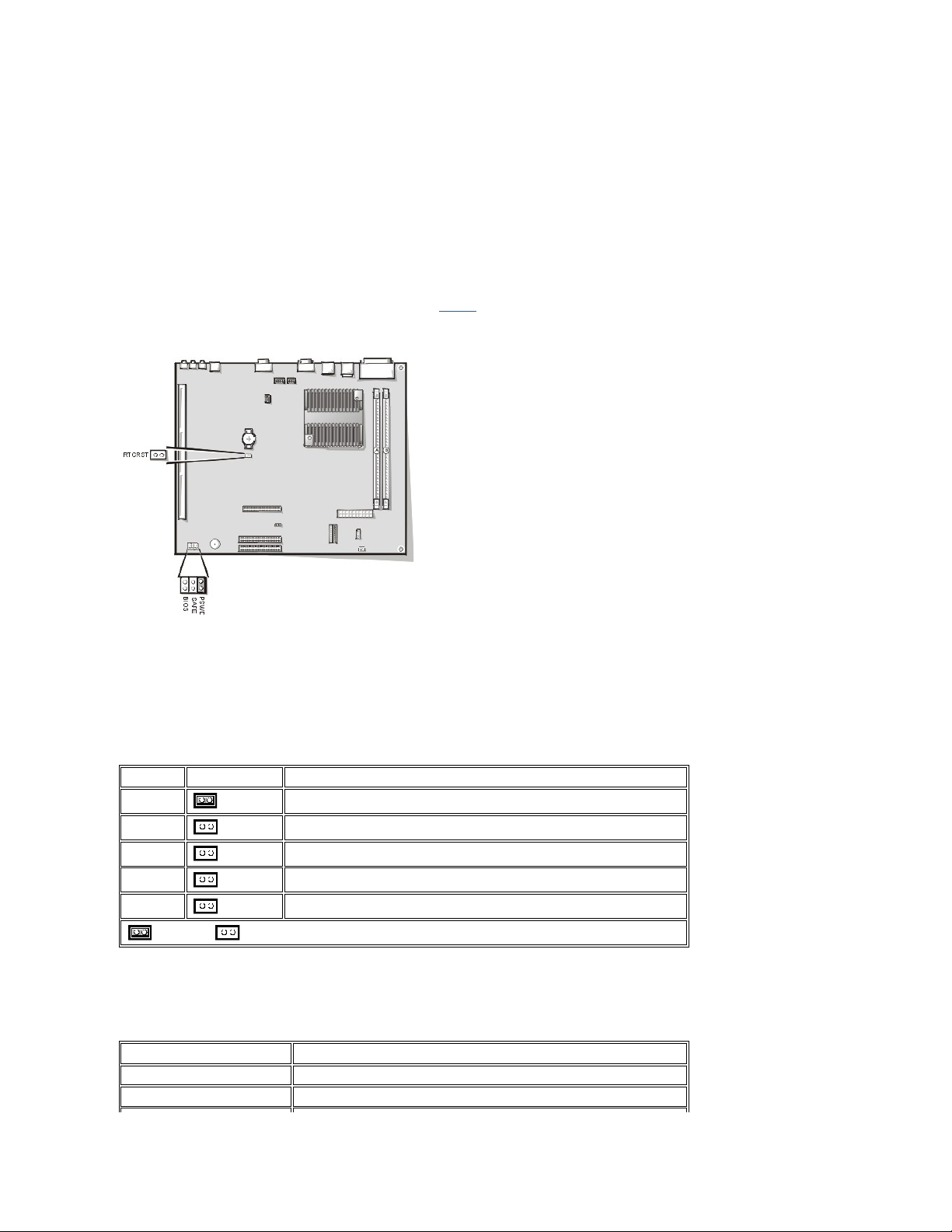
System Board Jumpers
Figure 18 shows the location of the jumpers on the system board. Table 1 lists the system board jumpers and their settings.
Figure 18. System Board Jumpers
Jumpers are small blocks on a circuit board with two or more pins emerging from them. Plastic plugs containing a wire fit down over the pins. The
wire connects the pins and creates a circuit.
NOTICE: Make sure your system is turned off before you change a jumper setting. Otherwise, damage to your system or
unpredictable results may occur.
To change a jumper setting, pull the plug off its pin(s) and carefully fit it down onto the pin(s) indicated.
2
Line-out connector
3
Microphone connector
4
NIC connector
5
Video connector
6
Serial port 2 connector
7
USB connectors (2)
8
Keyboard (lower) and mouse (upper) connectors
9
Parallel port (upper) and serial port 1 (lower) connectors
10
Microprocessor connector
11
RIMM sockets (2)
12
DC power 1 connector
13
DC power 2 connector
14
Chassis intrusion connector
15
Control panel connector
16
External speaker connector
17
EIDE1 connector
18
EIDE2 connector
19
System board speaker
20
System board jumpers
21
Diskette/tape-drive connector
22
Riser board connector
23
Real-time clock reset (RTCRST) jumper
24
Battery
25
Modem audio connector
26
Fan connector
27
CD audio cable connector
Page 13
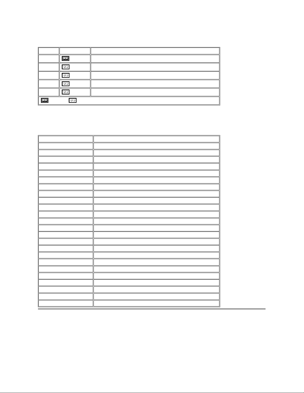
Table 1. System-Board Jumper Settings
System Board Labels
Table 2 lists the labels for connectors and sockets on your system board, and it gives a brief description of their functions.
Table 2. System Board Connectors and Sockets
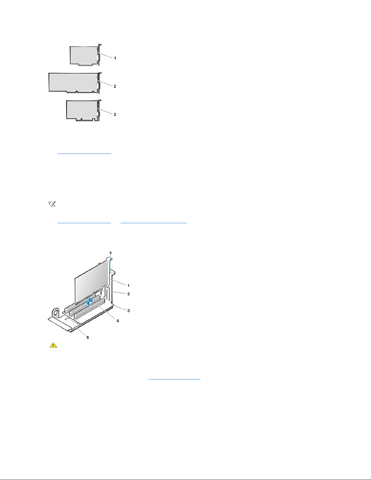
Expansion Cards
Each GX200 low-profile chassis can accommodate 32-bit PCI expansion cards and 16-bit and 8-bit ISA expansion cards, depending on the
installedriserboard.SeeFigure19forexamplesoftheexpansioncards.
Figure 19. Expansion Cards
Jumper
Setting
Description
PSWD
(default)
Password features are enabled.
(default)
Password features are disabled.
SAFE
(default)
Reserved (do not change).
BIOS
(default)
Reserved (do not change).
RTCRST
(default)
Real-time clock reset. Can be used for troubleshooting purposes.
jumpered unjumpered
Connector or Socket
Description
AMC
ATI multimedia channel connector
BATTERY
Battery socket
CD_IN
CD-ROM audio interface connector
RIMM_x
RIMM socket
DSKT
Diskette/tape drive interface connector
ENET
Integrated NIC connector
EXT_SPKR
External speaker connector
FAN
Microprocessor fan connector
HDLED
Hard-disk drive LED connector
IDEn
EIDE interface connector
INTRUDER
Chassis intrusion switch connector
KYBD
Keyboard connector
MODEM
Modem audio connector
MONITOR
Video connector
MOUSE
Mouse connector
PANEL
Control panel connector
PARALLEL
Parallel port connector; sometimes referred to as LPT1
PCIn*
PCI expansion-card connector
POWER_1
Main power input connector
POWER_2
3.3-V power input connector
RISER
Riser board connector
SERIALn
Serial port connector
SLOT1_PRI
Primary microprocessor connector
USB
USB connectors
Page 14
Expansion-Card Removal
To remove an expansion card, perform the following steps:
1. Remove the computer cover.
2. If necessary, disconnect any cables connected to the card.
3. Remove the screw on the mounting bracket of the card you want to remove.
4. Grasp the card by its outside corners, and ease it out of its connector.
5. If you are removing the card permanently, install a metal filler bracket over the empty card-slot opening.
6. Replace the computer cover and reset the chassis intrusion detector.
Expansion-Card Installation
Figure 20. Expansion-Card Installation
To install an expansion card, perform the following steps:
1. Prepare the expansion card for installation, and remove the computer cover.
See the documentation that came with the expansion card for information on configuring the card, making internal connections, or otherwise
customizing it for your system.
2. Remove the screw and remove the metal filler bracket that covers the card-slot opening for the expansion-card slot you intend to use (see
Figure 21).
Save the screw to use when installing the expansion card later in this procedure.
Figure 21. Filler Bracket Removal
1
8-bit ISA expansion card
2
16-bit ISA expansion card
3
32-bit PCI expansion card
NOTE: Installing filler brackets over empty card-slot openings is necessary to maintain Federal Communications Commission (FCC)
certification of the system. The brackets also keep dust and dirt out of your computer.
1
Expansion card
2
Card-edge connector
3
Riser board
4
Expansion-card connector
5
Expansion-card cage
CAUTION: Some network cards automatically start the system when they are connected. To guard
against electric shock, be sure to unplug your computer from its electrical outlet before installing any
expansion cards.
Page 15
3. Insert the expansion card into the expansion-card connector.
If the expansion card is full-length, insert the front end of the card into the corresponding card guide on the inside front of the chassis as you
insert the card into its connector. Insert the card's edge connector firmly into the expansion-card slot.
4. When the card is firmly seated in the connector, secure the card's mounting bracket to the chassis with the screw you removed in step 2.
5. Connect any cables that should be attached to the card.
See the documentation for the card for information about the card's cable connections.
6. Replace the computer cover and reset the chassis intrusion detector.
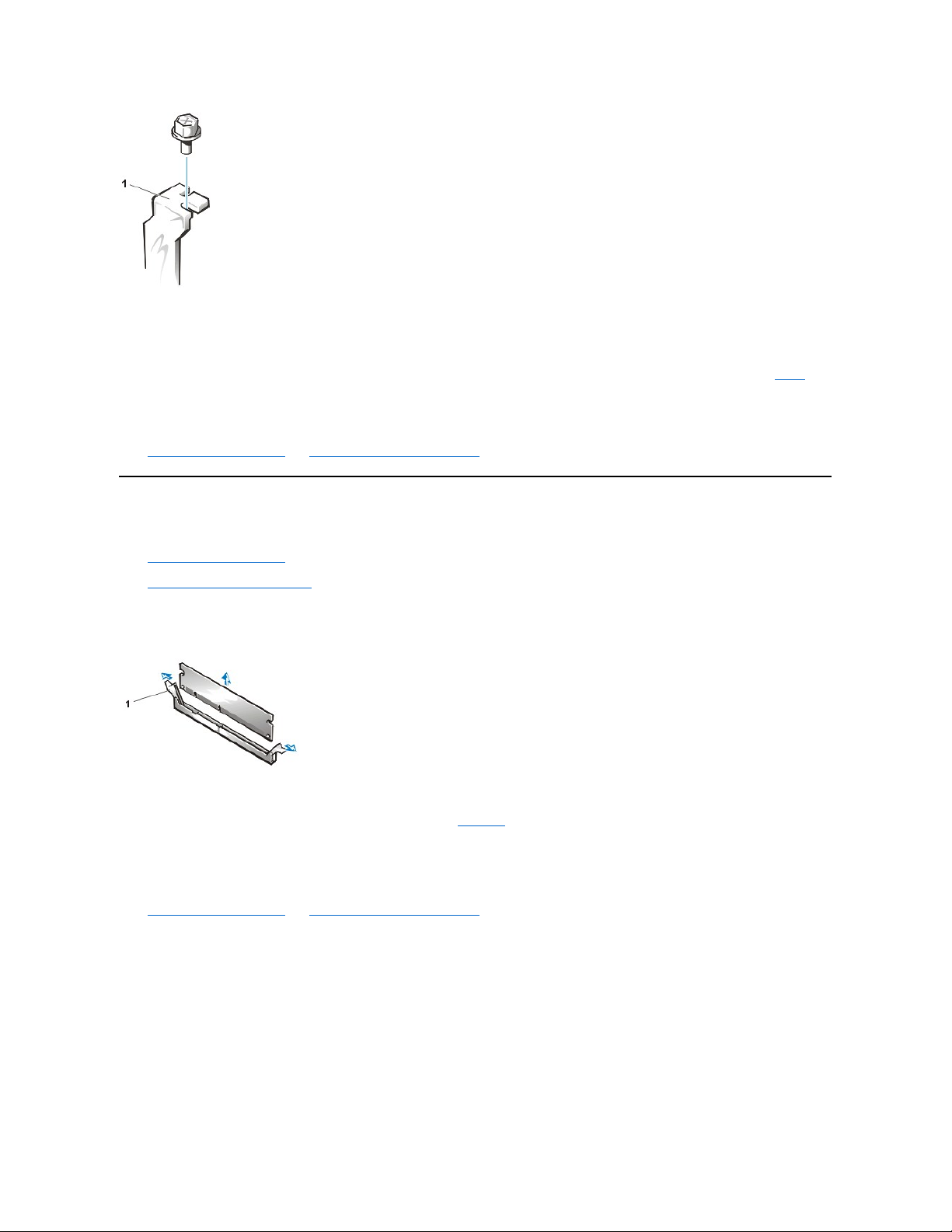
Memory
To remove a Rambus in-line memory module (RIMM), perform the following steps:
1. Remove the computer cover.
2. Remove the system power supply to allow you to access the RIMMs.
3. Press the securing clips outward simultaneously until the RIMM disengages and pops out slightly from the socket (see Figure 22).
Figure 22. Removing a RIMM
To reinstall a RIMM, perform the following steps:
1. Locate the plastic securing clips at each end of the socket (see Figure 23).
2. Press the clips outward until they snap open.
3. Press the RIMM straight into the slot running down the center of the socket until the securing tabs snap into place around the ends of the
RIMM.
4. Replace the computer cover and reset the chassis intrusion detector.
Figure 23. Installing a RIMM
1
Filler bracket
1
Securing clips (2)
Page 16
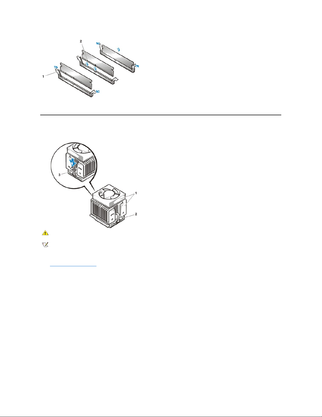
Microprocessor/Cooling Fan/Heat Sink Assembly
Figure 24. Microprocessor/Cooling Fan/Heat Sink Assembly
To replace a microprocessor, perform the following steps:
1. Remove the computer cover.
2. Disconnect the cooling fan power cable from its system board connector.
3. Remove the metal retaining clip that secures the heat sink assembly to the microprocessor package by gently pushing down on the folded
part of the retaining clip with a small screwdriver.
The retaining clip hooks over the sides of the zero insertion force (ZIF) socket.
4. Remove the heat sink assembly from the microprocessor package.
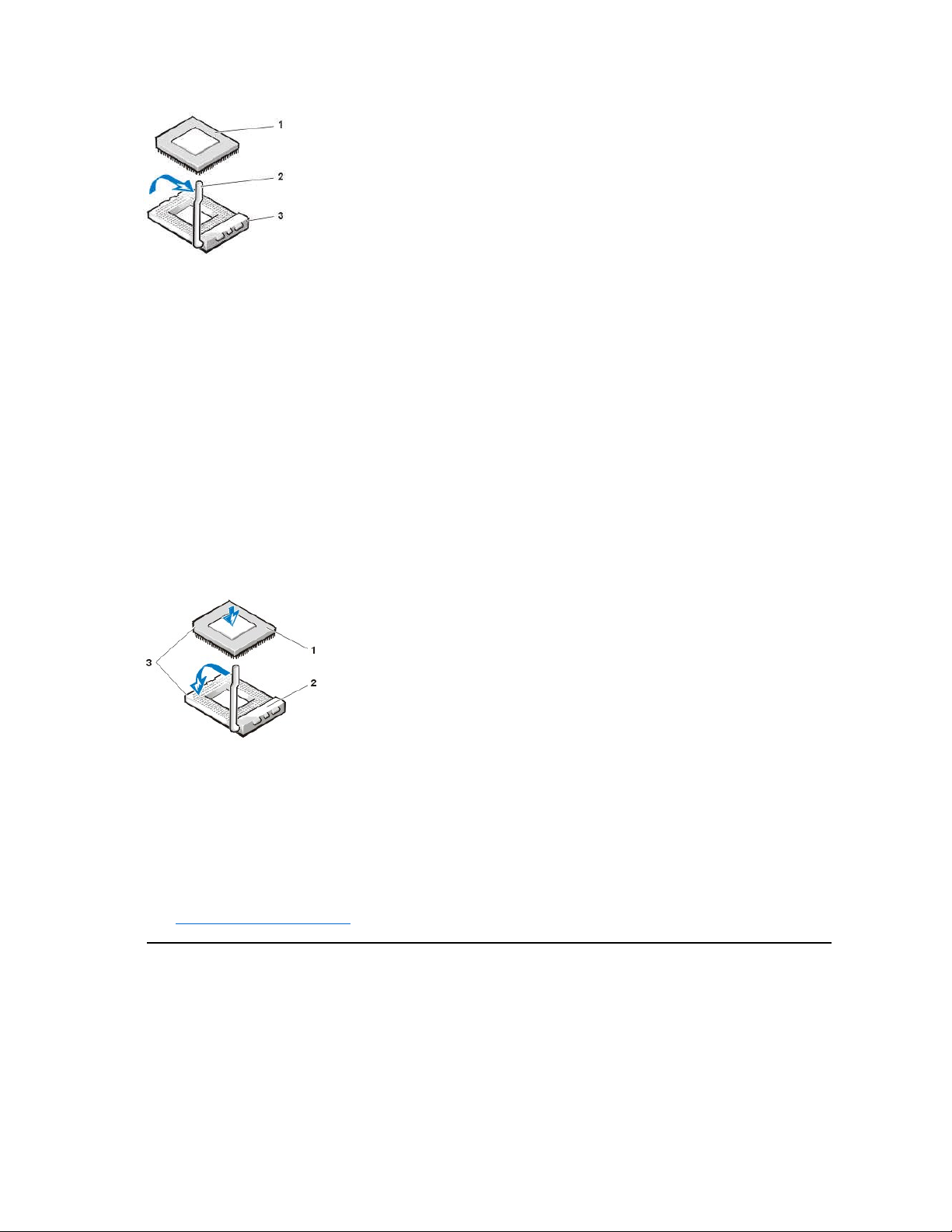
NOTICE: Be careful not to bend any of the pins when you remove the microprocessor package from the ZIF socket. Bending
the pins can permanently damage the microprocessor.
5. Detach and lift the microprocessor package away from the ZIF socket.
The ZIF socket has a lever-type handle that secures and releases the microprocessor package from the ZIF socket.
a. Pull the socket release lever straight out until the microprocessor package is released.
b. Remove the microprocessor package from the socket.
Leave the release lever extended so that the socket is ready for the new microprocessor.
Figure 25. Microprocessor Package Removal
1
Securing clips (2)
2
Notches (2)
1
Cooling fan/heat sink assembly
2
ZIF socket
3
Retaining clip
CAUTION: The microprocessor/heat sink assembly can get extremely hot. Be sure that the assembly has had sufficient time to
cool before you touch it.
NOTE: Dell recommends that only a technically knowledgeable person perform this procedure.
Page 17
6. Unpack the new microprocessor package.
If any of the pins on the new microprocessor appear to be bent, return the microprocessor package.
NOTICE: You must position the microprocessor package correctly in the ZIF socket to avoid permanent damage to the
microprocessor and the computer when you turn on the system.
7. Install the microprocessor package in the ZIF socket.
a. If the release lever on the ZIF socket is not all the way out, move it to that position.
b. Align pin-1 (the beveled corner) of the microprocessor package and pin-1 of the ZIF socket.
c. Set the microprocessor package lightly in the socket, making sure that all the pins are headed into the correct holes.
Because the system uses a ZIF socket, there is no need to use force (which could bend the pins if the microprocessor package is
misaligned).
d. When the microprocessor package is positioned correctly, press it with minimal pressure to fully seat it in the ZIF socket.
e. When the microprocessor package is fully seated, pivot the release lever back toward the system board until it snaps into place,
securing the microprocessor package.
Figure 26. Microprocessor Package Installation
8. Unpack the heat sink included in the replacement kit.
NOTICE: Do not reuse the old heat sink assembly when you replace the microprocessor package. Using the old heat sink
assembly can cause the microprocessor to overheat because there is not enough thermal compound between the old heat
sink assembly and the microprocessor package.
9. Replace the heat sink assembly.
a. Peel the release liner from the adhesive tape attached to the bottom of the new heat sink assembly.
b. Replace the computer cover and restart the system.
c. Reset the chassis intrusion detector. While in System Setup, confirm that the system data area correctly identifies the type of
microprocessor installed.
System Battery
Figure 27. System Battery Removal
1
Microprocessor package
2
Socket release lever
3
ZIF socket
1
Microprocessor
2
ZIF socket
3
Pin-1 (beveled corner)
Page 18
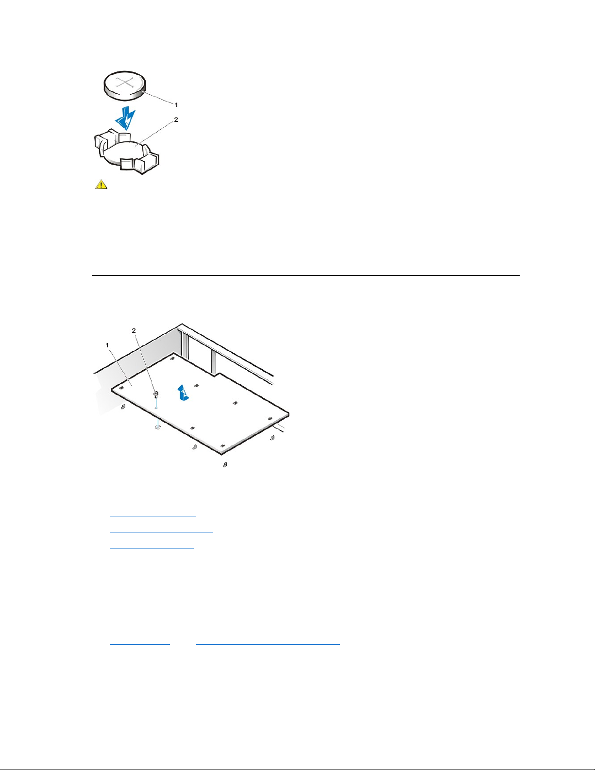
To remove the system battery, perform the following steps:
1. If possible, enter System Setup and print the System Setup screens.
2. Remove the system battery by carefully prying it out of its socket with your fingers or with a blunt, nonconducting object such as a plastic
screwdriver.
When you replace the system battery, orient the new battery with the "+" facing up. Insert the battery into its socket and snap it into place.
System Board
Figure 28. System Board Removal
To remove the system board, perform the following steps:
1. Disconnect all cables from their connectors at the back of the computer.
2. Remove the computer cover.
3. Remove the expansion-card cage.
4. Remove the 5.25-inch drive.
5. Disconnect all cables from the system board.
6. Remove the screw that secures the system board to the bottom of the chassis (see Figure 28).
7. Slide the system board toward the front of the chassis until it stops.
8. Carefully lift the system board out of the chassis (be sure to lift evenly and not twist the system board).
To replace the system board, perform the following steps:
1. Remove the RIMMs and the microprocessor/cooling fan/heat sink assembly, and install them on the replacement board.
2. Set the jumpers on the new system board so that they are identical to those on the old board, unless you are installing a
microprocessor upgrade.
3. Push down near each slot to engage the grounding clip onto its corresponding tab.
1
Battery
2
Socket
CAUTION: There is a danger of the new battery exploding if it is incorrectly installed. Replace the battery only with the same or
equivalent type recommended by the manufacturer. Discard used batteries according to the manufacturer’s instructions.
1
Systemboard
2
Screw
Page 19

4. Push evenly on both sides of the system board as you slide and lock it into position (do not twist the system board).
5. Reconnect all cables to the system board.
6. Replace the 5.25-inch drive.
7. Replace the expansion-card cage.
8. Replace the computer cover.
9. Reset the chassis intrusion detector. While in System Setup, confirm that the system data area correctly identifies the type of
microprocessor installed.
Back to Contents Page
Page 20
Back to Contents Page
Midsize Chassis — Removing and Replacing Parts: Dell™OptiPlex™GX200System
Service Manual
Overview
This section provides procedures for removing and replacing the components, assemblies, and subassemblies in the Dell OptiPlex 200 midsize
chassis system.
Unless otherwise noted, each procedure assumes that the following conditions exist:
l You have performed the steps in "Precautionary Measures."
l You have removed the computer cover.
You can replace or reinstall a part by performing the removal procedure in reverse order unless additional information is provided.
Recommended Tools
The procedures in this file require the use of a #2 Phillips-head screwdriver.
Also, use a wrist grounding strap as explained in "Precautionary Measures."
Precautionary Measures
Before you perform any procedure in this section, take a few moments to read the following caution for your personal safety and to prevent
damage to the system from electrostatic discharge (ESD).
Overview
System Power Supply
Recommended Tools
System Board Components
Precautionary Measures
Expansion Cards
Computer Cover
Riser Boards
Internal View
Memory
Front-Panel Inserts
Microprocessor/Airflow Shroud/Heat Sink Assembly
Expansion-Card Cage
System Battery
Control Panel
System Board
Drives
CAUTION: FOR YOUR PERSONAL SAFETY AND PROTECTION OF THE EQUIPMENT
Before you start to work on the system, perform the following steps in the sequence listed:
1. Turn off the computer and all peripherals.
2. Disconnect the computer and peripherals from their electrical outlets. Also, disconnect any telephone or telecommunication lines from
the computer. Doing so reduces the potential for personal injury or shock.
3. If you are disconnecting a peripheral from the computer or are removing a component from the system board, wait 10 to 20 seconds
after disconnecting the computer from the electrical outlet before disconnecting the peripheral or removing the component to avoid
possible damage to the system board.
4. Wear a wrist grounding strap, and clip it to an unpainted metal surface, such as the padlock loop on the back of the chassis. If a wrist
grounding strap is not available, touch any unpainted metal surface on the back of the computer or on the computer chassis, such as
thepowersupply,todischargeanystaticchargefromyourbodybeforetouchinganythinginsidethecomputer.Whileyouwork,
periodically touch an unpainted metal surface on the computer chassis to dissipate any static electricity that might harm internal
components. Also avoid touching components or contacts on a card and avoid touching pins on a chip.
5. Verify that the standby power indicator
on the riser board is not on. If it is on, you may need to wait 10 to 30 seconds for it to go out (see
Page 21
Computer Cover
Figure 1. Computer Cover Removal
To remove the computer cover, perform the following steps:
1. Turn off your computer and peripherals, and observe the caution for your personal safety and protection of the equipment described in
"Precautionary Measures."
2. If you have installed a padlock through the padlock ring on the back panel, remove the padlock.
3. Press in on the two securing buttons until the cover is free to swing up (see Figure 1).
4. Raise the back of the cover, and pivot it toward the front of the computer.
5. Lift the cover off the hooks at the front of the chassis.
Figure 2. Computer Cover Replacement
To replace the computer cover, perform the following steps:
1. Check all cable connections, especially those that might have come loose during your work. Fold cables out of the way so that they do not
catch on the computer cover. Make sure cables are not routed over the drive cage—they will prevent the cover from closing properly.
2. Facing the left side of the computer, hold the cover at a slight angle as shown in Figure 2.
3. Fit the three cover hooks into the rectangular slots on the chassis. (It might be helpful to look down into the chassis to verify that the hooks are
in place.)
4. Pivot the cover down toward the back and into position. Make sure that the two securing buttons click into place.
To reset the chassis intrusion detector, perform the following steps:
1. Reconnect all cables to their connectors at the back of the computer.
Riser Boards).
1
Securing buttons (2)
1
Release buttons (2)
2
Hooks in slots (4)
Page 22
2. Restart the system.
3. Enter System Setup. To do this, press <F2> when F2=Setup appears in the upper-right corner of the screen.
If the operating system begins to load into memory, allow the system to complete the load operation, shut down the system, and try again.
4. Restore the system configuration settings.
5. While in System Setup, perform the following steps to configure the system if it has an LS-120 SuperDisk drive:
a. Set Diskette Drive A and Diskette Drive B to Not Installed.
b. Set Secondary Drive 0 or Secondary Drive 1, as appropriate, to Auto.
c. Go to the second page and set Diskette to Off.
6. While in System Setup, reset the chassis intrusion detector under the System Security tab by changing Chassis Intrusion to Enabled,
Enabled-Silent, or Disabled.
7. If no other changes are required in System Setup, press <Esc> and follow the menu directions to reboot the system and implement the
changes.
8. Run the Dell Diagnostics to verify that the system is operating correctly.
Internal View
Figure 3 shows the chassis with the cover removed.
Figure 3. Inside the Chassis
Front-Panel Inserts
Figure4.5.25-Inch Front-Panel Insert Removal (cutaway view through top of cover)
NOTE: If the system does not have an audio expansion card but does have an integrated audio controller, be sure that the
Sound setting is On. If the system has an audio expansion card, be sure that the Sound setting is Off.
1
Drive in upper bay
2
Internal drive cage
3
Chassis intrusion switch
4
Drive interface cable
5
Expansion-card cage
6
Security cable slot
7
I/O ports and connectors
8
AC power receptacle
9
Padlock ring
10
Power supply
11
System board
12
Drive interface cable
Page 23
To remove a 5.25-inch front-panel insert, perform the following steps:
1. Hold the bezel with the front facing you.
2. From the front of the top cover, use your thumbs to press inward on the insert until it snaps free of the cover.
To replace a 5.25-inch front-panel insert, position the two ring-tabs over the posts on the inside of the bay opening, and then press the ring tabs
over the posts.
Expansion-Card Cage
Figure 5. Control Panel Removal
To remove the card cage, complete the following steps:
1. Rotate the lever toward the back of the computer until it stops in the upright position.
2. Lift the expansion-card cage up and away from the computer.
To replace an expansion-card cage, keep the cage flush against the chassis to ensure that the lever engages the notch when the lever is
depressed.
Control Panel
Figure 6. Control Panel Removal
1
5.25-inch front-panel insert
2
Ring tabs (2)
3
Posts (2)
1
Slots (2)
2
Tabs (2)
3
Securing lever
Page 24

To remove the control panel, perform the following steps:
1. Remove the hard-disk drive cage.
2. Disconnect the control panel cable from the PANEL connector on the system board (see Figure 14 or the internal service label for the
location of the PANEL connector).
3. Remove the mounting screw holding the control panel to the chassis.
4. Slide the control panel out of the hooks holding it to the chassis.
Note the routing of the control panel cable as you remove it from the chassis.
To reinstall the control panel, perform the removal procedure in reverse.
Drives
3.5-Inch Diskette Drive Removal
To remove the 3.5-inch diskette drive assembly, perform the following steps:
1. Remove the computer cover.
2. Disconnect the DC power and cables from the diskette drive.
3. Remove the mounting screw (see Figure 7).
4. Rotate the diskette drive upward and lift it free.
When you replace the 3.5-inch diskette drive on the bracket, be sure that the two retaining tabs on the right side of the bracket engage the
mounting holes in the side of the 3.5-inch diskette drive. Rotate the drive down. Then replace the screw that holds the diskette drive to the bracket.
Figure 7. 3.5-Inch Diskette Drive Bracket
5.25-Inch Drive Removal
To remove a device from an externally accessible drive bay, perform the following steps:
1. Remove the computer cover.
1
Chassis hooks (2)
2
Mounting screw
3
Control panel
4
Control panel cable
NOTE: In all of the following procedures, left and right refer to your left and right as you face the front of the computer.
1
3.5-inch diskette drive
2
Retaining tabs (2)
3
Bracket
4
Screw
Page 25
2. Disconnect the DC power and data cables from the back of the drive.
3. Squeeze the retaining tabs that extend from each side of the drive bracket and slide the bracket out of the bay (see Figure 8).
4. Turn the drive assembly upside down and unscrew the four screws that secure the drive to the bracket (see Figure 9).
To install a 5.25-inch drive, perform the 5.25-inch drive removal procedure in reverse and reset the chassis intrusion detector.
Figure 8. 5.25-Inch Drive Removal
Figure 9. Drive Bracket
Hard-Disk Drive Removal
1. Remove the computer cover.
2. Remove the drive bracket from the chassis.
If a hard-disk drive is already installed on the drive bracket, disconnect the DC power cable and EIDE cable from the drive.
3. Remove the screw securing the hard-disk drive bracket to the front wall of the chassis. Grasp the front part of the bracket that serves as a
handle, and rotate the bracket up toward the back of the computer until it disengages from the floor of the chassis (see Figure 10).
Figure 10. Hard-Disk Drive Bracket Removal
NOTE: For easier access inside the chassis, you may want to rotate the power supply out of the way temporarily.
1
Bracket tabs (2)
1
Metal tabs (2)
2
Drive bracket
Page 26

4. Slide the drive into the chosen bay of the bracket, orienting it so that the connectors on the back of the drive face the back of the chassis—
and the power input connector is closest to the floor of the chassis—when the bracket is reinstalled (see Figure 11).
Figure 11. Hard-Disk Drive Insertion
5. Align the four screw holes of the drive and bracket. Insert and tighten the screws that came with your upgrade kit (see Figure 11).
If you are replacing a drive in the 1.6-inch slot, use the four screw holes in the side of the bracket. If you are replacing a drive in the 1-
inch slot, use the four screw holes in the bottom of the bracket.
Hard-Disk Drive Replacement
1. Reinstall the hard-disk drive bracket in the chassis.
Hold the bracket by its handle, so that it stays at the proper tilt. Let it brush the side of the drive cage as you lower it into the chassis
until the two tabs at the bottom back of the bracket (see Figure 11) fit flush against the front of the rail that extends across the chassis
floor and the horizontal lip at the back fits over the rail (see Figure 12).
Rotate the bracket down into position, and reinstall the screw you removed in step 3.
NOTICE: You must match the colored strip on the EIDE cable with pin 1 on the IDE1 connector to avoid possible damage to your
system.
2. Connect one of the device connectors on the EIDE cable to the 40-pin interface connector on the back of the hard-disk drive (see Figure 12).
The cable is keyed so that the colored edge of the EIDE cable lines up with the pin-1 end of the interface connector.
Figure 12. Hard-Disk Drives Cables Attachment
1
"Handle" on bracket
2
Screw securing drive to chassis
1
Drive bracket
2
Tabs (2)
3
1.6-inch drive
4
Screws (4)
NOTE: Ultra Advanced Technology Attachment (ATA)/66 hard-disk drives require an 80-conductor cable to transfer data at
full speed. The 80-conductor cable has a 40-pin connector just like the Ultra ATA/33 cable but has twice as many wires
within the cable itself. If you use an Ultra ATA/33 cable with Ultra ATA/66 hard-disk drives, they will transfer data at Ultra
ATA/33 speeds.
Page 27

NOTICE: You must match the colored strip on the EIDE cable with pin 1 on the IDE1 connector to avoid possible damage to your
system. Pin 1 is indicated by a silk-screened "1" printed on the system board.
3. If it is not already connected, connect the other end of the EIDE cable to the appropriate EIDE interface connector on the system board.
To locate the IDE1 connector on the system board, see Figures 19 and 20.
4. Connect a DC power cable into the power input connector on the back of the drive (see Figure 12).
Check all connectors to be certain that they are properly cabled and firmly seated.
5. Replace the computer cover. Then reconnect your computer and peripherals to their electrical outlets, and turn on the peripherals.
6. Insert a bootable diskette into drive A, and turn on the computer system.
7. Reset the chassis intrusion detector. While in System Setup, update the Drive 0 option under Primary Drive n.
8. Partition and logically format your drive before proceeding to the next step.
See the documentation for your operating system for instructions.
9. Install your operating system on your hard-disk drive.
Refer to the documentation that came with your operating system.
System Power Supply
System Power Supply Rotation
To access some components on the system board, you may have to rotate the system power supply out of the way. To rotate the power supply,
perform the following steps:
1. Remove the computer cover.
2. Disconnect the AC power cable from the AC power receptacle on the back of the power supply (see Figure 13).
Figure 13. System Power Supply Rotation
3. Free the power supply from the securing tab labeled "RELEASE—>, " and rotate it upward until it locks in its extended position.
System Power Supply Removal
1
Interface connector
2
Power input connector on drive
3
Lip4Rail5IDE1 connector
6
IDE2 connector
7
DC power cable
8
EIDE cable
1
Securing tab
2
Power supply
3
Release latch
4
AC power cable
Page 28
To remove the system power supply, perform the following steps:
1. Rotate the system power supply.
2. Disconnect the power cables from all drives.
3. Remove the power supply cables from the system board.
4. Lift the front of the power supply until it stops. Then rotate the power supply away from the chassis.
5. Lift the power supply out of the chassis.
System Power Supply Installation
To reinstall the system power supply, align the swivel points at the rear of the power supply with the holes in the chassis and power supply support
arm. Then perform the removal procedure in reverse.
System Board Components
Figure 14 shows the system board and the location of all its sockets and connectors.
Figure 14. System Board Components
1
Line-in connector
2
Line-out connector
3
Microphone connector
4
NIC connector
5
Video connector
6
Serial port 2 connector
7
USB connectors (2)
8
Keyboard (lower) and mouse (upper) connectors
9
Parallel port (upper) and serial port 1 (lower) connectors
10
Microprocessor connector
11
RIMM sockets (2)
12
DC power 1 connector
13
DC power 2 connector
14
Chassis intrusion connector
15
Control panel connector
16
External speaker connector
17
EIDE1 connector
18
EIDE2 connector
19
System board speaker
20
System board jumpers
Page 29
System Board Jumpers
Figure 15 shows the location of the jumpers on the system board. Table 1 lists the system board jumpers and their settings.
Figure 15. System Board Jumpers
Jumpers are small blocks on a circuit board with two or more pins emerging from them. Plastic plugs containing a wire fit down over the pins. The
wire connects the pins and creates a circuit.
NOTICE: Make sure your system is turned off before you change a jumper setting. Otherwise, damage to your system or
unpredictable results may occur.
To change a jumper setting, pull the plug off its pin(s) and carefully fit it down onto the pin(s) indicated.
Table 1. System-Board Jumper Settings
System Board Labels
Table 2 lists the labels for connectors and sockets on your system board, and it gives a brief description of their functions.
Table 2. System Board Connectors and Sockets
21
Diskette/tape-drive connector
22
Riser board connector
23
Real-time clock reset (RTCRST) jumper
24
Battery
25
Modem audio connector
26
Fan connector
27
CD audio cable connector
Jumper
Setting
Description
PSWD
(default)
Password features are enabled.
(default)
Password features are disabled.
SAFE
(default)
Reserved (do not change).
BIOS
(default)
Reserved (do not change).
RTCRST
(default)
Real-time clock reset. Can be used for troubleshooting purposes.
jumpered unjumpered
Connector or Socket
Description
AMC
ATI multimedia channel connector
BATTERY
Battery socket
Page 30

Expansion Cards
The system accommodates up to six expansion cards, including up to five 32-bit PCI expansion cards and one 32-bit AGP card. (See Figure 16
for examples of these cards.)
Figure 16. Expansion Cards
Expansion-Card Removal
To remove an expansion card, perform the following steps:
1. Remove the computer cover.
2. Remove the expansion-card cage.
3. If necessary, disconnect any cables connected to the card.
4. Unscrew the mounting bracket of the card you want to remove.
CD_IN
CD-ROM audio interface connector
RIMM_x
RIMM socket
DSKT
Diskette/tape drive interface connector
ENET
Integrated NIC connector
EXT_SPKR
External speaker connector
FAN
Microprocessor fan connector
HDLED
Hard-disk drive LED connector
IDEn
EIDE interface connector
INTRUDER
Chassis intrusion switch connector
KYBD
Keyboard connector
MODEM
Modem audio connector
MONITOR
Video connector
MOUSE
Mouse connector
PANEL
Control panel connector
PARALLEL
Parallel port connector; sometimes referred to as LPT1
PCIn*
PCI expansion-card connector
POWER_1
Main power input connector
POWER_2
3.3-V power input connector
RISER
Riser board connector
SERIALn
Serial port connector
SLOT1_PRI
Primary microprocessor connector
USB
USB connectors
NOTES: Before disconnecting a peripheral from the system or removing a component from the system board, verify that the standby
power LED on the system board is off. For the location of this LED, see Figures 19 and 20.
1
8-bit ISA expansion card
2
16-bit ISA expansion card
3
32-bit PCI expansion card
Page 31

5. Grasp the card by its outside corners, and ease it out of its connector.
6. If you are removing the card permanently, install a metal filler bracket over the empty card-slot opening.
7. Replace the expansion-card cage.
8. Replace the computer cover and reset the chassis intrusion detector.
Figure 17. Expansion Card Removal
Expansion-Card Replacement
To replace an expansion card, perform the following steps.
1. Prepare the expansion card for installation, and remove the computer cover.
See the documentation that came with the expansion card for information on configuring the card, making internal connections, or
otherwise customizing it for your system.
2. Remove the expansion-card cage.
3. If the card-slot opening for the slot you intend to use is covered by a metal filler bracket unscrew and remove the bracket (see Figure 18).
Save the screw to use when installing the expansion card later in this procedure.
Figure 18. Filler Bracket Removal
4. Insert the expansion card into the expansion-card connector.
If the expansion card is full-length, insert the front end of the card into the corresponding card guide on the inside front of the chassis as you
insert the card into its connector. Insert the card's edge connector firmly into the expansion-card slot. Gently rock the card into the connector
until it is fully seated.
NOTE: Installing filler brackets over empty card-slot openings is necessary to maintain Federal Communications Commission (FCC)
certification of the system. The brackets also keep dust and dirt out of your computer.
1
Card-edge connector
2
Expansion card
3
Riser board
4
Expansion-card connector
5
Expansion-card cage
CAUTION: See "Precautionary Measures."
CAUTION: Some network cards automatically start up the system when they are connected. To guard against electric shock,
be sure to unplug your computer from its electrical outlet before installing any expansion cards.
1
Filler bracket
Page 32

5. When the card is firmly seated in the connector, secure the card's mounting bracket to the chassis with the screw you removed in step 3.
6. Replace the expansion-card cage.
7. Connect any cables that should be attached to the card.
8. See the documentation for the card for information about the card's cable connections.
9. If you are installing the entry-level OptiPlex sound card, disconnect the internal speaker cable from the system board and reconnect it to the
INT SPKR connector on the sound card. You may have to route the speaker cable through a hole in the front of the chassis to reach the sound
card connector.
10. Replace the computer cover and reset the chassis intrusion detector.
Riser Boards
The midsize chassis is available with either a PCI riser board (see Figure 19) or a PCI/ISA riser board (see Figure 20). The PCI riser board
provides five PCI expansion card slots. The PCI/ISA riser board provides two PCI expansion slots, two ISA expansion slots, and one shared
PCI/ISA expansion slot.
Figure 19. Midsize Chassis PCI Riser Board
Figure 20. PCI/ISA Riser Board
Memory
To remove a Rambus in-line memory module (RIMM), perform the following steps:
1. Remove the computer cover.
2. Rotate the system power supply to allow you to access the RIMMs.
3. Press the securing clips outward simultaneously until the RIMM disengages and pops out slightly from the socket (see Figure 21).
Figure 21. RIMM Removal
1
Standby power indicator (AUX_LED)
2
PCI expansion slot 5 (PCI5)
3
PCI expansion slot 4 (PCI4)
4
Remote Wakeup header (WOL)
5
PCI expansion slot 1 (PCI1)
6
PCI expansion slot 2 (PCI2)
7
PCI expansion slot 3 (PCI3)
1
Standby power indicator LED (AUX_LED)
2
ISA expansion slot 3 (ISA3)
3
ISA expansion slot 2 (ISA2)
4
ISA expansion slot 1 (ISA1)
5
Remote Wakeup header (WOL)
6
PCI expansion slot 1 (PCI1)
7
PCI expansion slot 2 (PCI2)
8
PCI expansion slot 3 (PCI3)
Page 33

To reinstall a RIMM, perform the following steps:
1. Locate the plastic securing clips at each end of the socket (see Figure 22).
2. Press the clips outward until they snap open.
3. Press the RIMM straight into the slot running down the center of the socket until the securing tabs snap into place around the ends of the
RIMM.
4. Replace the computer cover and reset the chassis intrusion detector.
Figure 22. RIMM Installation
Microprocessor/Airflow Shroud/Heat Sink Assembly
To replace a microprocessor, perform the following steps:
1. Remove the computer cover.
2. Rotate the power supply out of the way.
3. Pull up on the airflow shroud release tabs on the sides at the bottom of the shroud while you lift the shroud straight up and out of the chassis.
Figure 23. Removing the Airflow Shroud
1
Securing clips (2)
1
Securing clips (2)
2
Notches (2)
CAUTION: The microprocessor/heat sink assembly can get extremely hot. Be sure that the assembly has had sufficient time to
cool before you touch it.
NOTE: Dell recommends that only a technically knowledgeable person perform this procedure.
1
Airflow shroud
2
Release tabs
3
Heat sink assembly
Page 34

4. Remove the metal retaining clip that secures the heat sink assembly to the microprocessor package by gently pushing down on the folded
part of the retaining clip with a small screwdriver.
The retaining clip hooks over the sides of the zero insertion force (ZIF) socket.
Figure 24. Heat Sink Assembly Removal
5. Remove the heat sink assembly from the microprocessor package.
NOTICE: Be careful not to bend any of the pins when you remove the microprocessor package from the ZIF socket. Bending
the pins can permanently damage the microprocessor.
6. Detach and lift the microprocessor package away from the ZIF socket.
The ZIF socket has a lever-type handle that secures and releases the microprocessor package from the ZIF socket.
a. Pull the socket release lever straight out until the microprocessor package is released.
b. Remove the microprocessor package from the socket.
Leave the release lever extended so that the socket is ready for the new microprocessor.
Figure 25. Microprocessor Package Removal
7. Unpack the new microprocessor package.
If any of the pins on the new microprocessor appear to be bent, return the microprocessor package.
NOTICE: You must position the microprocessor package correctly in the ZIF socket to avoid permanent damage to the
microprocessor and the computer when you turn on the system.
8. Install the microprocessor package in the ZIF socket.
a. If the release lever on the ZIF socket is not all the way out, move it to that position.
b. Align pin-1 (the beveled corner) of the microprocessor package and pin-1 of the ZIF socket.
c. Set the microprocessor package lightly in the socket, making sure that all the pins are headed into the correct holes.
Because the system uses a ZIF socket, there is no need to use force (which could bend the pins if the microprocessor package is
misaligned).
d. When the microprocessor package is positioned correctly, press it with minimal pressure to fully seat it in the ZIF socket.
e. When the microprocessor package is fully seated, pivot the release lever back toward the system board until it snaps into place,
1
Retaining clip
2
Heat sink assembly
3
Microprocessor package
4
ZIF socket
1
Microprocessor package
2
Socket release lever
3
ZIF socket
Page 35

securing the microprocessor package.
Figure 26. Microprocessor Package Installation
9. Unpack the heat sink included in the replacement kit.
NOTICE: Do not reuse the old heat sink assembly when you replace the microprocessor package. Using the old heat sink
assembly can cause the microprocessor to overheat because there is not enough thermal compound between the old heat
sink assembly and the microprocessor package.
10. Replace the heat sink assembly.
a. Peel the release liner from the adhesive tape attached to the bottom of the new heat sink assembly.
b. Place the heat sink assembly on top of the microprocessor package.
c. Orient the metal retaining clip and hook the unhinged end of the clip over the tab on the top edge of the ZIF socket.
d. Press down on the hinged end of the clip to snap the clip over the tab on the bottom edge of the ZIF socket.
11. Replace the airflow shroud.
a. Place the airflow shroud over the microprocessor/heat sink assembly.
b. Fit the mouth of the shroud into the alignment slot on the left side of the fan and between the fan and the power supply bracket on the
right.
c. Squeeze both pairs of tabs on the sides of the shroud and lower it until the clips on the bottom of the shroud engage the top of the ZIF
socket.
12. Rotate the power supply back into place.
13. Replace the computer cover.
14. Reset the chassis intrusion detector. While in System Setup, confirm that the system data area correctly identifies the type of microprocessor
installed.
System Battery
Figure 27. System Battery Removal
To remove the system battery, perform the following steps:
1
Microprocessor
2
ZIF socket
3
Pin-1 (beveled corner)
1
Battery
2
Socket
CAUTION: There is a danger of the new battery exploding if it is incorrectly installed. Replace the battery only with the same or
equivalent type recommended by the manufacturer. Discard used batteries according to the manufacturer’s instructions.
Page 36

1. If possible, enter System Setup and print the System Setup screens.
2. Remove the computer cover.
3. Remove the system battery by carefully prying it out of its socket with your fingers or with a blunt, nonconducting object such as a plastic
screwdriver.
When you replace the system battery, orient the new battery with the "+" facing up. Insert the battery into its socket and snap it into place.
4. Replace the computer cover and reset the chassis intrusion detector.
System Board
Figure 28. System Board Removal
To remove the system board, perform the following steps:
1. Remove the computer cover.
2. Disconnect all cables from the system board.
3. Rotate the system power supply out of the way.
4. Remove the RIMMs.
5. Remove the microprocessor.
6. Remove the AGP card brace and the AGP video card.
7. Slide all externally accessible drives and brackets partially out of the chassis.
8. Slide the hard-disk drive partially out of the chassis.
9. Remove the screw that secures the system board to the bottom of the chassis (see Figure 28).
10. Slide the system board toward the front of the chassis until it stops.
11. Carefully raise the front of the system board and lift the board out of the chassis at an angle.
To replace the system board, perform the following steps:
1. Install the RIMMs and the microprocessor/airflow shroud/heat sink assembly on the replacement board.
2. Configure the settings of the replacement board.
Set the jumpers on the replacement system board so that they are identical to those on the existing system board, unless you are performing
a microprocessor upgrade.
3. Replace the system board in the chassis.
4. Push down near each slot to engage the grounding clip onto its corresponding tab.
5. Push evenly on both sides of the system board as you slide and lock it into position (do not twist the system board).
6. Reinstall the mounting screw.
1
System
board
2
Screw
Page 37

7. Reinstall all components on the system board by performing steps 2 through 8 of the removal process in reverse.
8. Replace the computer cover.
9. Reset the chassis intrusion detector. While in System Setup, confirm that the system data area correctly identifies the type of microprocessor
installed.
Back to Contents Page
Page 38

Back to Contents Page
Mini Tower Chassis — RemovingandReplacingParts:Dell™OptiPlex™GX200
Systems Service Manual
Overview
This section provides procedures for removing and replacing the components, assemblies, and subassemblies in the Dell OptiPlex mini tower
chassis GX200 system.
Unless otherwise noted, each procedure assumes that the following conditions exist:
l You have performed the steps in "Precautionary Measures."
l You have removed the computer cover.
l You can replace or reinstall a part by performing the removal procedure in reverse order unless additional information is provided.
Recommended Tools
Most of the procedures in this file require the use of one or more of the following tools:
l Small flat-blade screwdriver
l Wide flat-blade screwdriver
l #1 and #2 Phillips-head screwdrivers
l 1/4-inch nut driver
Also, use a wrist grounding strap as explained in "Precautionary Measures."
Precautionary Measures
Before you perform any of the procedures in this file, take a few moments to read the following caution for your personal safety and to prevent
damage to the system from electrostatic discharge (ESD).
Overview
Drives
Recommended Tools
System Power Supply
Precautionary Measures
Expansion-Card Cage
Internal Views
Riser Boards
Computer Cover
System Board Components
Front Bezel
Expansion Cards
Eject, Power, and Reset Buttons
Memory
Front-Panel Inserts
Microprocessor/Airflow Shroud/Heat Sink Assembly
Control Panel
System Battery
Chassis Intrusion Switch
System Board
CAUTION: FOR YOUR PERSONAL SAFETY AND PROTECTION OF THE EQUIPMENT
Before you start to work on the system, perform the following steps in the sequence listed:
1. Turn off the computer and all peripherals.
2. Disconnect the computer and peripherals from their electrical outlets. Also, disconnect any telephone or telecommunication lines from
the computer. Doing so reduces the potential for personal injury or shock.
3. If you are disconnecting a peripheral from the computer or are removing a component from the system board, wait 10 to 20 seconds
after disconnecting the computer from the electrical outlet before disconnecting the peripheral or removing the component to avoid
Page 39

Internal Views
Figure 1 shows a side view of the mini tower chassis computer to help orient you when you work inside the computer.
Figure 1. Mini Tower Chassis Orientation View
Figure 2 shows the mini tower chassis with the cover removed.
Figure 2. Inside the Mini Tower Chassis
Computer Cover
Figure 3. Computer Cover Removal
possible damage to the system board.
4. Wear a wrist grounding strap, and clip it to an unpainted metal surface, such as the padlock loop on the back of the chassis. If a wrist
grounding strap is not available, touch any unpainted metal surface on the back of the computer or on the computer chassis, such as
thepowersupply,todischargeanystaticchargefromyourbodybeforetouchinganythinginsidethecomputer.Whileyouwork,
periodically touch an unpainted metal surface on the computer chassis to dissipate any static electricity that might harm internal
components. Also avoid touching components or contacts on a card and avoid touching pins on a chip.
5. Verify that the auxiliary power indicator on the riser board is not on. If it is on, you may need to wait 10 to 30 seconds for it to go out
(see Riser Boards).
1
System board
2
Power supply
3
5.25-inch drive slots
4
Internal hard-disk drive bracket
5
Expansion-card cage
6
Bottom of computer
1
5.25-inch drive slots
2
Hard-disk drive bracket
3
Chassis intrusion switch
4
Hard-disk drive interface cable
5
Expansion-card cage
6
System board
7
Riserboard
8
Padlock ring
9
Security cable slot
10
I/O ports and connectors
11
AC power receptacle
12
Power supply
Page 40

To remove the mini tower computer cover, perform the following steps:
1. Face the back of the computer and slide the upper half of the padlock ring to the left to unlock the cover release
mechanism (see Figure 3).
2. Face the left side cover and press the release button, located at the bottom-left corner of the front bezel (see Figure 3).
3. Lift the bottom of the cover, allowing it to pivot up toward you.
4. Disengage the tabs that secure the cover to the top of the chassis, and lift the cover away.
Figure 4. Computer Cover Replacement
To replace the mini tower computer cover, perform the following steps:
1. Face the left side of the computer and hold the cover at a slight angle, as shown in Figure 4.
2. Align the top of the cover with the top of the chassis and insert the hooks on the cover into the recessed slots on the computer chassis so that
the tabs catch the hooks inside the slots.
3. Pivot the cover down toward the bottom of the chassis and into position.
Make sure that the securing hooks at the bottom of the cover click into place.
4. If you are using a padlock to secure your system, reinstall the padlock.
To reset the chassis intrusion detector, perform the following steps:
1. Reconnect all cables to their connectors at the back of the computer.
2. Restart the system.
3. Enter System Setup. To do this, press <F2> when F2=Setup appears in the upper-right corner of the screen.
If the operating system begins to load into memory, allow the system to complete the load operation, shut down the system, and try again.
4. Restore the system configuration settings.
1
Hook2Recessed slot
NOTE: If the system does not have an audio expansion card but does have an integrated audio controller, be sure that the
Sound setting is On. If the system has an audio expansion card, be sure that the Sound setting is Off.
Page 41
5. While in System Setup, perform the following steps to configure the system if it has an LS-120 SuperDisk drive:
a. Set Diskette Drive A and Diskette Drive B to Not Installed.
b. Set Secondary Drive 0 or Secondary Drive 1, as appropriate, to Auto.
c. Go to the second page and set Diskette to Off.
6. While in System Setup, reset the chassis intrusion detector under the System Security tab by changing Chassis Intrusion to Enabled,
Enabled-Silent, or Disabled.
7. If no other changes are required in System Setup, press <Esc> and follow the menu directions to reboot the system and implement the
changes.
8. Run the Dell Diagnostics to verify that the system is operating correctly.
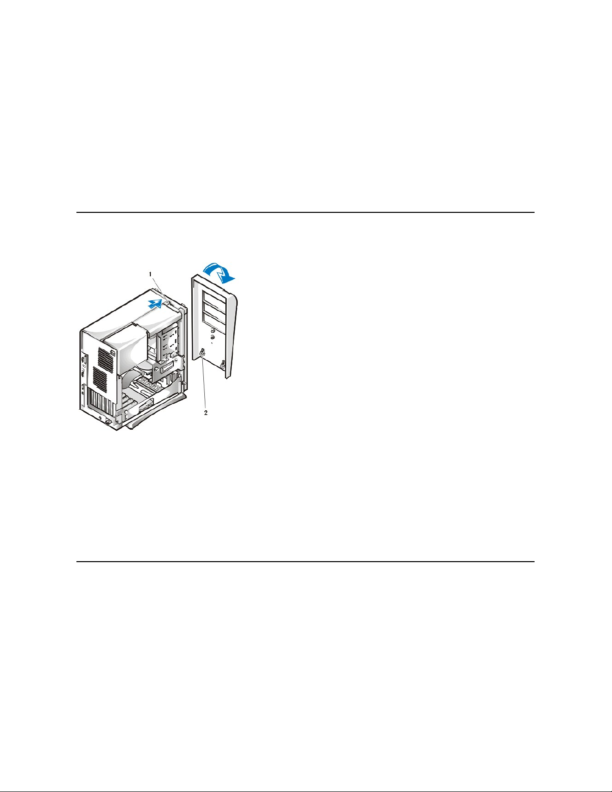
Front Bezel
Figure 5. Front Bezel Removal
To remove the front bezel, perform the following steps:
1. While pressing the tab release marked with the icon, tilt the bezel away from the chassis.
2. Disengage the two retaining hooks at the bottom of the bezel.
3. Carefully pull the bezel away from the chassis.
To replace the front bezel, perform the following steps:
1. Fit the two retaining hooks on the bezel into their corresponding slots at the bottom of the mini tower chassis.
2. Rotate the bezel toward the chassis until the tabs on the top of the chassis snap into their slots on the bezel.
Eject, Power, and Reset Buttons
Figure 6. Eject, Power, and Reset Button Removal
1
Tab release
2
Retaining hooks (2)
Page 42

To remove the eject, power, and reset buttons, perform the following steps:
1. Lay the front bezel on a flat work surface, with the back of the bezel facing up.
2. To remove the 3.5-inch diskette eject button, pull gently on the plastic part of the button until it comes free.
3. To remove the power button or the reset button, use a small screwdriver and push in the two or three plastic clips that hold the button to the
bezel.
When these clips are released, the buttons come free from the bezel.
Front-Panel Inserts
Figure7.5.25-Inch Front-Panel Insert Removal
To remove a 5.25-inch front-panel insert, perform the following steps:
1. Hold the bezel with the front facing you.
2. From the front of the bezel, use your thumbs to press inward on the insert until it snaps free of the bezel.
To replace a 5.25-inch front-panel insert, position the two ring-tabs over the posts on the inside of the bay opening, and then press the ring-tabs
over the posts.
Control Panel
Figure 8. Control Panel Removal
1
Diskette eject button
2
Power button
3
Reset button
1
Front panel insert
2
Bezel3Ring-tab (2)
Page 43

To remove the control panel, perform the following steps:
1. Disconnect the control panel cable from the control panel connector on the system board (see "System Board Labels" for the location of the
PANEL connector).
Note the routing of the control panel cable as you remove it from the chassis.
2. Disconnect the the chassis intrusion switch cable connector from the control panel.
3. Remove the mounting screw that secures the control panel to the chassis.
4. Remove the control panel cable.
5. Pull the control panel cable through the opening in the front wall, and carefully remove the cable from the routing tab in the chassis.
6. Pull out on the control panel to detach it from the chassis.
Note the routing of the control panel cable as you remove it from the chassis.
Chassis Intrusion Switch
Figure9.ChassisIntrusionSwitchRemoval
To remove the chassis intrusion switch, perform the following steps:
1
Control panel
2
Control panel connector
3
Chassis intrusion cable connector
4
Chassis intrusion switch
1
Control panel
2
Control panel cable connector
3
Chassis intrusion cable connector
4
Chassis intrusion switch
Page 44

1. Remove the control panel from the front panel.
2. Disconnectthechassisintrusionswitchcablefromthecontrolpanel (see Figure 9).
Note the routing of the chassis intrusion cable as you remove the cable from the chassis. Chassis hooks may hold the cable in place inside
the chassis.
3. Slide the chassis intrusion switch out of its slot on the chassis and carefully remove the switch and its attached cable from the chassis.
4. Install the replacement chassis intrusion switch and cable.
5. Reset the chassis intrusion detector.
Drives
Figure 10. Drive Locations
3.5-Inch Diskette Drive
Figure 11. Diskette Drive Removal
To remove the 3.5-inch diskette drive from the drive bay, perform the following steps:
1. Disconnect the DC power and diskette interface cable from the back of the drive.
2. Press the release tab on the left side of the diskette drive, and pull the diskette drive/bracket out of the chassis.
3. Remove the drive-mountingscrewfromtheleftsideofthedrive,andremovethedrivefromthebracket(seeFigure11).
NOTE: In all of the following procedures, left and right refer to your left and right as you face the front of the computer.
1
3.5-inch diskette drive
2
5.25-inch drive slots (3)
3
3.5-inch internal bay for hard-disk drives (2)
1
Release tab
Page 45

When you replace the 3.5-inch diskette drive, be sure that the two hooks on the right side of the bracket engage the mounting holes in the side of
the 3.5-inch diskette drive.
5.25-Inch Drive
Figure 12. 5.25-Inch Drive Removal
To remove a 5.25-inch drive from a drive bay, perform the following steps.
1. Remove the front bezel.
2. Disconnect the DC power cable and the interface cable from the back of the drive.
3. Squeeze the metal tabs that extend from each side of the drive bracket toward each other, and pull the bracket out of the bay (see Figure
12).
4. Lay the 5.25-inch drive/bracket assembly upside down and remove the four screws that secure the drive to the bracket.
To replace the 5.25-inch drive, perform the following steps:
1. Turn the drive upside down, and locate the four screw holes around its perimeter.
2. Place the front of the drive toward the front of the bracket; then install the four screws, but do not tighten them.
3. Align the screws with the score marks on the bracket, and tighten the screws in the order stamped on the bottom of the bracket.
4. Check the alignment of the computer cover around the 5.25-inch bezel. Adjust the drive forward or backward on the bracket to align it.
5. To ensure proper installation, align all screw holes and ensure that the tabs on the front of the bracket are flush with the front of the drive (see
Figure13).
Figure 13. Drive Bracket Attachment
6. To further ensure proper positioning of the drive in the bracket, insert and tighten all four screws in the order in which the holes are
numbered (the holes are labeled "1" through "4").
7. Slidethedriveintothedrivebayuntilthedrivesnapssecurelyintoplace(seeFigure14).
Make sure that both bracket tabs snap into place in the drive bay.
1
Bracket tabs (2)
NOTE: For easier access inside the chassis, you may want to rotate the power supply up until it locks (see Figure 20).
1
5.25-inch drive
2
Bracket tabs (2)
3
Bracket
Page 46
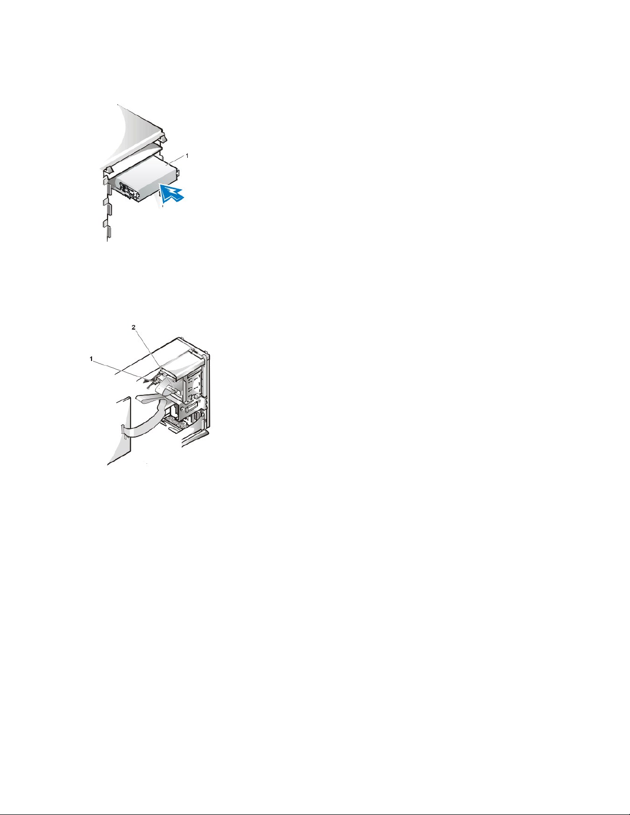
Figure 14. New Drive Insertion
NOTICE: You must match the colored strip on the cable with pin 1 on the drive's interface connector to avoid possible damage to
your system.
8. ConnectaDCpowercabletothepowerinputconnectoronthebackofthedrive(seeFigure15).
Figure 15. 5.25-Inch Drive Cables Attachment
9. Connect the appropriate EIDE interface cable to the EIDE interface connector on the back of the drive (see Figure 15).
If your system came with an EIDE CD-ROM or tape drive, use the spare connector on the existing interface cable. Otherwise, use the EIDE
interface cable provided in the drive kit.
Hard-Disk Drive Removal
Figure 16. Hard-Disk Drive Bracket Removal
1
5.25-inch drive
1
DC power cable
2
EIDE interface connector (on drive)
Page 47

To remove a hard-disk drive from the mini tower's internal hard-disk drive bracket, perform the following steps.
1. If you are replacing a hard-disk drive that contains data you want to keep, make a backup copy of your files before you continue this
procedure.
2. Remove the computer cover.
3. Remove the front bezel.
4. Open the drive bracket from the chassis:
a. Disconnect the DC power cable and EIDE cable from the drive.
b. Remove the screw securing the hard-disk drive bracket to the chassis.
c. Grasp the bracket, and rotate it outward from the chassis until the sliding tab clears the slide rail on the chassis (see Figure 16).
d. Lift the bracket up slightly to free its hinge tabs from the chassis hinge slots.
5. Remove the bracket from the chassis.
Figure 17. Hard-Disk Drive Removal From Bracket
6. Remove the four screws that hold the drive in the bracket (see Figure 17).
Retain the screws for use with the replacement hard-disk drive.
7. Remove the drive by sliding it out of the bracket.
Hard-Disk Drive Replacement
Toinstallareplacementhard-diskdrive,performthefollowingsteps.
1
Drive bracket slide rail
2
Chassis hinge slots
3
Hinge tabs
4
Sliding tab
5
Drive bracket
CAUTION: To avoid the possibility of electric shock, turn off the computer and any peripherals, disconnect them from
electrical outlets, and then wait at least 5 seconds before you remove the computer cover. Also, before you remove a drive,
see the other precautions in "Precautionary Measures."
1
Screws (4)
2
Sliding tab
3
Drive bracket
4
1.6-inch drive
Page 48

NOTICE: To avoid possibly damaging the drive by ESD, ground yourself by touching an unpainted metal surface on the back of the
computer.
NOTICE: When you unpack the drive, do not set it on a hard surface, which may damage the drive. Instead, set the drive on a
surface, such as a foam pad, that will sufficiently cushion it.
1. Prepare the drive for installation.
Check the documentation for the drive to verify that it is configured for your computer system.
2. If not already done, remove the computer cover.
3. If not already done, remove the drive bracket from the chassis.
4. Slide the drive into the chosen bay of the bracket, orienting the drive so that the connectors on the back of the drive will face the back of the
chassis when you reinstall the bracket (see Figure18).
5. Align the four screw holes of the drive and bracket. Insert and tighten the screwsfromthehard-disk drive you removed in the previous
procedure:
l If you are installing a drive in the 1.6-inch bay, use the four screw holes in the side of the bracket (see Figure 17).
l If you are installing a drive in the 1-inch bay, use the four screw holes in the bottom of the bracket.
6. Reinstall the hard-disk drive bracket in the chassis (see Figure 18):
a. Insert the bracket's hinge tabs into the chassis hinge slots so that the tabs hook over the hinge slots.
b. Rotate the bracket toward the chassis, and fit the bracket's sliding tab on the chassis slide rail.
c. Slide the bracket into place, and reinstall the screw you removed in step 4 of the previous procedure.
Figure 18. Drive Bracket Insertion Into Chassis
7. Connect a power cable to the power input connector on the back of the drive (see Figure 19).
Check all connectors to be certain that they are properly cabled and firmly seated.
NOTICE: You must match the red-colored stripe on the EIDE cable with pin 1 on the drive's interface connector to avoid
possible damage to your system.
8. Connect the cable connector on the EIDE cable to the 40-pin interface connector on the back of the hard-disk drive.
Figure 19. Hard-Disk Drive Cables Attachment
CAUTION: To avoid the possibility of electric shock, turn off the computer and any peripherals, disconnect them from
electrical outlets, and then wait at least 5 seconds before you remove the computer cover. Also, before you install a drive, see
the other precautions in "Precautionary Measures."
1
Chassis slide rail
2
Chassis hinge slots
3
Hinge tabs
4
Sliding tabs
Page 49

NOTICE: You must match the blue connector on the interface cable to the IDE1 connector on the system board to avoid possible
damage to your system.
9. If it is not already connected, connect the blue connector of the EIDE cable to the IDE1 connector on the system board.
To locate the IDE1 connector, see "System Board Components."
10. Replace the computer cover. Then reconnect your computer and peripherals to their electrical outlets, and turn them on.
11. If the drive you just installed is the primary drive, insert a bootable diskette into the diskette drive (usually drive A).
12. Reset the chassis intrusion detector. While in System Setup, update the appropriate Primary Drive option, 0 or 1.
13. Partition and logically format your drive before you proceed to the next step.
See the documentation for your operating system for instructions.
14. If the drive you just installed is the primary drive, install your operating system on the hard-disk drive.
For instructions, refer to the documentation that came with your operating system.
System Power Supply
Figure 20. Power Supply Removal
To remove the system power supply, perform the following steps:
1. Disconnect the AC power cable from the back of the power supply.
2. Free the system power supply from the securing tab labeled "RELEASE —>" androtateitupwarduntilitlocks.
3. DisconnecttheDCpowercablesfromthesystemboardandthedrives.
Note the routing of the DC power cables underneath the tabs in the chassis as you remove them from the system board and drives. It is
important to route these cables properly when you replace them to prevent them from being pinched or crimped.
4. RemovethescrewabovetheACpowerreceptacle.
5. Lift up on the power supply cradle tab to release the power supply from the cradle and slide the power supply toward the front of the computer
approximately 1 inch.
1
Blue interface connector (on EIDE1)
2
Interface cable
3
Power cable
4
Power input connector on drive
5
Interface connector on drive
1
AC power cable
2
AC power receptacle
3
Power supply cradle
4
DC power cables
5
Securing tab
Page 50

6. Lowerthepowersupplydownandawayfromthecomputer.
Expansion-Card Cage
To remove the expansion-card cage, perform the following steps:
1. Examine any cables connected to expansion cards through the back-panel openings and disconnect any cables that will not reach to where
the cage must be placed upon removal from the chassis.
2. Locatethesecuringlever(seeFigure21). Rotate the lever upward until it stops in an upright position.
Figure 21. Expansion-Card Cage Removal
3. Slide the expansion-card cage out of the chassis.
4. Lift the expansion-card cage up and away from the chassis.
To replace the expansion-card cage, perform the following steps:
1. With the securing lever in the upright position, align the expansion-card cage tabs with the slots in the chassis opening for the expansioncard cage (see Figure 21). Slide the expansion-card cage into place.
2. Rotate the securing lever downward, until it is flush with the top side of the chassis. Make sure that the riser board is fully seated in the RISER
connector on the system board (see Figure22).
3. Reconnect any cables you removed in step 1 of the previous procedure.
Riser Boards
The mini tower chassis is available with either a PCI riser board (see Figure 22) or a PCI/ISA riser board (see Figure 23). The PCI riser board
provides five PCI expansion card slots. The PCI/ISA riser board provides three PCI expansion slots, two ISA expansion slots, and two shared
PCI/ISA expansion slots.
Figure 22. Mini Tower Chassis PCI Riser Board
NOTICE: Use a wrist grounding strap as explained in "Precautionary Measures."
1
Securing lever
2
Tabs (2)
3
Slots (2)
Page 51

Figure 23. Mini Tower Chassis PCI/ISA Riser Board
To remove a riser board, perform the following steps.
NOTICE: To avoid possibly damaging expansion cards or the system board by ESD, ground yourself by touching an unpainted
metal surface on the back of the computer.
1. Remove the expansion-card cage.
2. Remove the expansion cards installed in the slots.
3. Remove the screws securing the riser board to the expansion-card cage.
System Board Components
Figure 24 shows the system board and the location of all its sockets and connectors.
Figure 24. System Board Components
1
Auxiliary power indicator (AUX_LED)
2
PCI expansion slot 5 (PCI5)
3
Wake On LAN (WOL) connector
4
PCI expansion slot 1 (PCI1)
5
Auxiliary power connector
1
PCI expansion slot 1 (PCI1)
2
PCI expansion slot 2 (PCI2)
3
PCI expansion slot 3 (PCI3)
4
PCI expansion slot 4 (PCI4)
5
ISA expansion slot 1 (ISA1)
6
Standby power indicator LED (AUX_LED)
7
ISA expansion slot 4 (ISA4)
8
ISA expansion slot 3 (ISA3)
9
ISA expansion slot 2 (ISA2)
10
PCI expansion slot 5 (PCI5)
11
Remote Wakeup header (WOL)
Page 52

System Board Jumpers
Figure 25 shows the location of the jumpers on the system board. Table 1 lists the system board jumpers and their settings.
Figure 25. System Board Jumpers
1
Line-in connector
2
Line-out connector
3
Microphone connector
4
NIC connector
5
Video connector
6
Serial port 2 connector
7
USB connectors (2)
8
Keyboard (lower) and mouse (upper) connectors
9
Parallel port (upper) and serial port 1 (lower) connectors
10
Microprocessor connector
11
RIMM sockets (2)
12
DC power 1 connector
13
DC power 2 connector
14
Chassis intrusion connector
15
Control panel connector
16
External speaker connector
17
EIDE1 connector
18
EIDE2 connector
19
System board speaker
20
System board jumpers
21
Diskette/tape-drive connector
22
Riser board connector
23
Real-time clock reset (RTCRST) jumper
24
Battery
25
Modem audio connector
26
Fan connector
27
CD audio cable connector
Page 53

Jumpers are small blocks on a circuit board with two or more pins emerging from them. Plastic plugs containing a wire fit down over the pins. The
wire connects the pins and creates a circuit.
NOTICE: Make sure your system is turned off before you change a jumper setting. Otherwise, damage to your system or
unpredictable results may occur.
To change a jumper setting, pull the plug off its pin(s) and carefully fit it down onto the pin(s) indicated.
Table 1. System-Board Jumper Settings
System Board Labels
Table 2 lists the labels for connectors and sockets on your system board, and it gives a brief description of their functions.
Table 2. System Board Connectors and Sockets
Jumper
Setting
Description
PSWD
(default)
Password features are enabled.
(default)
Password features are disabled.
SAFE
(default)
Reserved (do not change).
BIOS
(default)
Reserved (do not change).
RTCRST
(default)
Real-time clock reset. Can be used for troubleshooting purposes.
jumpered unjumpered
Connector or Socket
Description
AMC
ATI multimedia channel connector
BATTERY
Battery socket
CD_IN
CD-ROM audio interface connector
RIMM_x
RIMM socket
DSKT
Diskette/tape drive interface connector
ENET
Integrated NIC connector
EXT_SPKR
External speaker connector
FAN
Microprocessor fan connector
HDLED
Hard-disk drive LED connector
IDEn
EIDE interface connector
INTRUDER
Chassis intrusion switch connector
KYBD
Keyboard connector
MODEM
Modem audio connector
Page 54

Expansion Cards
Each GX200 chassis can accommodate 32-bit PCI expansion cards and 16-bit and 8-bit ISA expansion cards, depending on the installed riser
board.SeeFigure26forexamplesoftheexpansioncards.
Figure 26. Expansion Cards
Expansion Card Removal
To remove an expansion card, perform the following steps:
1. Remove the computer cover.
2. If necessary, disconnect any cables connected to the card.
3. Remove the screw from the mounting bracket of the card you want to remove.
4. Grasp the card by its outside corners, and ease it out of its connector.
5. If you are removing the card permanently, install a metal filler bracket over the empty card-slot opening.
6. Replace the computer cover and reset the chassis intrusion detector.
Expansion Card Installation
Figure 27. Expansion Card Installation
MONITOR
Video connector
MOUSE
Mouse connector
PANEL
Control panel connector
PARALLEL
Parallel port connector; sometimes referred to as LPT1
PCIn*
PCI expansion-card connector
POWER_1
Main power input connector
POWER_2
3.3-V power input connector
RISER
Riser board connector
SERIALn
Serial port connector
SLOT1_PRI
Primary microprocessor connector
USB
USB connectors
1
8-bit ISA expansion card
2
16-bit ISA expansion card
3
32-bit PCI expansion card
NOTE: Installing filler brackets over empty card-slot openings is necessary to maintain Federal Communications
Commission (FCC) certification of the system and keep dust and dirt out of your computer.
Page 55

To install an expansion card, perform the following steps:
1. Prepare the expansion card for installation, and remove the computer cover.
See the documentation that came with the expansion card for information on configuring the card, making internal connections, or otherwise
customizing it for your system.
2. Remove the screw and remove the metal filler bracket that covers the card-slot opening for the expansion slot you intend to use (see Figure
28).
Save the screw to use when installing the expansion card later in this procedure.
Figure 28. Filler Bracket Removal
3. Insert the expansion card into the expansion-card connector.
If the expansion card is full-length, insert the front end of the card into the corresponding card guide on the inside front of the chassis as you
insert the card into its connector. Insert the card's edge connector firmly into the expansion-card slot.
4. When the card is firmly seated in the connector, secure the card's mounting bracket to the chassis with the screw you removed in step 2.
5. Connect any cables that should be attached to the card.
See the documentation provided with the card for information about the card's cable connections.
6. Replace the computer cover and reset the chassis intrusion detector.
Memory
To remove a Rambus in-line memory module (RIMM), perform the following steps:
1. Remove the computer cover.
2. Remove the system power supply to allow you to access the RIMMs.
3. Press the securing clips outward simultaneously until the RIMM disengages and pops out slightly from the socket (see Figure 29).
1
Card-edge connector
2
Expansion card
3
Riser board
4
Expansion-card connector
5
Expansion-card cage
CAUTION: Some network cards automatically start up the system when they are connected. To
guard against electric shock, be sure to unplug your computer from its electrical outlet before
installing any expansion cards.
1
Filler bracket
Page 56
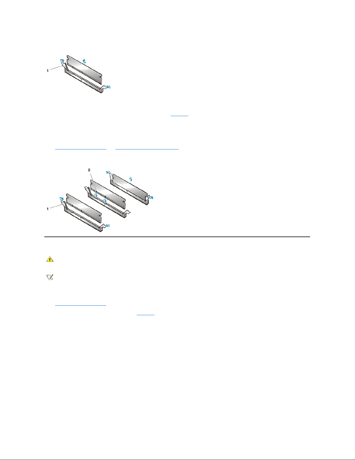
Figure 29. RIMM Removal
To reinstall a RIMM, perform the following steps:
1. Locate the plastic securing clips at each end of the socket (see Figure 30).
2. Press the clips outward until they snap open.
3. Press the RIMM straight into the slot running down the center of the socket until the securing tabs snap into place around the ends of the
RIMM.
4. Replace the computer cover and reset the chassis intrusion detector.
Figure 30. RIMM Installation
Microprocessor/Airflow Shroud/Heat Sink Assembly
To replace a microprocessor, perform the following steps:
1. Remove the computer cover.
2. Rotate the power supply up until it locks (see Figure 20).
3. Pull up on the airflow shroud release tabs while you lift and rotate the bottom of the shroud up and away from the back of the chassis and
microprocessor/heat sink assembly.
Figure 31. Microprocessor/Airflow Shroud/Heat Sink Removal
1
Securing clips (2)
1
Securing clips (2)
2
Notches (2)
CAUTION: The microprocessor SEC cartridge/heat sink assembly can get extremely hot. Be sure that the assembly has had
sufficient time to cool before you touch it.
NOTE: Dell recommends that only a technically knowledgeable person perform this procedure.
Page 57

4. Remove the metal retaining clip that secures the heat sink assembly to the microprocessor package by gently pushing down on the folded
part of the retaining clip with a small screwdriver.
The retaining clip hooks over the sides of the zero insertion force (ZIF) socket.
Figure 32. Heat Sink Assembly Removal
5. Remove the heat sink assembly from the microprocessor package.
NOTICE: Be careful not to bend any of the pins when you remove the microprocessor package from the ZIF socket. Bending
the pins can permanently damage the microprocessor.
6. Detach and lift out the microprocessor package from the ZIF socket.
The ZIF socket has a lever-type handle that secures and releases the microprocessor package from the ZIF socket.
a. Pull the socket release lever straight out until the microprocessor package is released.
b. Remove the microprocessor package from the socket.
Leave the release lever extended so that the socket is ready for the new microprocessor.
Figure 33. Microprocessor Package Removal
1
Airflow shroud hooks (2)
2
Chassis tabs (2)
3
Airflow shroud
4
Release tabs
5
Heat sink assembly
1
Retaining clip
2
Heat sink assembly
3
Microprocessor package
4
ZIF socket
1
Microprocessor package
2
Socket release lever
3
ZIF socket
Page 58

7. Unpack the new microprocessor package.
If any of the pins on the new microprocessor appear to be bent, return the microprocessor package.
NOTICE: You must position the microprocessor package correctly in the ZIF socket to avoid permanent damage to the
microprocessor and the computer when you turn on the system.
8. Install the microprocessor package in the ZIF socket.
a. If the release lever on the ZIF socket is not all the way out, move it to that position.
b. Align pin-1 (the beveled corner) of the microprocessor package and pin-1 of the ZIF socket.
c. Set the microprocessor package lightly in the socket, making sure that all the pins are headed into the correct holes.
Because the system uses a ZIF socket, there is no need to use force (which could bend the pins if the microprocessor package is
misaligned).
d. When the microprocessor package is positioned correctly, press it with minimal pressure to fully seat it in the ZIF socket.
e. When the microprocessor package is fully seated, pivot the release lever back toward the system board until it snaps into place,
securing the microprocessor package.
Figure 34. Microprocessor Package Installation
9. Unpack the heat sink included in the replacement kit.
NOTICE: Do not reuse the old heat sink assembly when you replace the microprocessor package. Using the old heat sink
assembly can cause the microprocessor to overheat because there is not enough thermal compound between the old heat
sink assembly and the microprocessor package.
10. Replace the heat sink assembly.
a. Peel the release liner from the adhesive tape attached to the bottom of the new heat sink assembly.
b. Place the heat sink assembly on top of the microprocessor package.
c. Orient the metal retaining clip and hook the unhinged end of the clip over the tab on the top edge of the ZIF socket.
d. Press down on the hinged end of the clip to snap the clip over the tab on the bottom edge of the ZIF socket.
11. Replace the airflow shroud.
a. Insert the two chassis hooks on the airflow shroud into the chassis tabs located above the system cooling fan.
b. Position the shroud at an angle to the chassis then rotate the shroud down over the microprocessor/heat sink assembly.
c. Squeeze both pairs of tabs on the sides of the shroud and lower it until the clips on the bottom of the shroud engage the top of the ZIF
socket.
12. Rotate the power supply back into place (see Figure 20).
13. Replace the computer cover.
14. Reset the chassis intrusion detector. While in System Setup, confirm that the system data area correctly identifies the type of microprocessor
installed.
System Battery
Figure 35. System Battery Removal
1
Microprocessor
2
ZIF socket
3
Pin-1 (beveled corner)
Page 59

To remove the system battery, perform the following steps:
1. If possible, enter System Setup and print the System Setup screens.
2. Rotate the power supply up until it locks (see Figure 20).
3. Remove the system battery by carefully prying it out of its socket with your fingers or with a blunt, nonconducting object, such as a plastic
screwdriver.
When you replace the system battery, orient the new battery with the "+" facing up. Insert the battery into its socket and snap it into
place.
System Board
Figure 36. System Board Removal
To remove the system board, perform the following steps:
1. Place the computer on its side on a flat surface.
2. Disconnect all cables from their connectors at the back of the computer.
3. Remove the expansion-card cage.
4. Unlatch and rotate the power supply until it locks (see Figure 20).
5. Remove the airflow shroud from the microprocessor.
6. Disconnect all cables from the system board.
7. Remove the screw that secures the system board to the bottom of the chassis.
8. Slide the system board toward the front of the chassis until it stops.
9. Carefully lift the system board out of the chassis (be sure to lift evenly and not twist the system board).
To replace the system board, perform the following steps:
1
Battery
2
Socket
CAUTION: There is a danger of the new battery exploding if it is incorrectly installed. Replace the battery only with the same or
equivalent type recommended by the manufacturer. Discard used batteries according to the manufacturer’s instructions.
1
Systemboard
2
Screw
Page 60

1. Remove the RIMMs and the microprocessor/airflow shroud/heat sink assembly, and install them on the replacement board.
2. Set the jumpers on the new system board so that they are identical to those on the old board, unless you are installing a microprocessor
upgrade.
3. Push down near each slot to engage the grounding clip onto its corresponding tab.
4. Push evenly on both sides of the system board as you slide and lock it into position (do not twist the system board).
5. Reconnect all cables to the system board.
6. Replace the airflow shroud.
7. Replace the expansion-card cage.
8. Rotate the power supply back into place (see Figure 20).
9. Replace the computer cover.
10. Reset the chassis intrusion detector. While in System Setup, confirm that the system data area correctly identifies the type of microprocessor
installed.
Back to Contents Page
Page 61

Back to Contents Page
Small Form-Factor Chassis — RemovingandReplacingParts:Dell™OptiPlex™GX200
Systems Service Manual
Overview
This section provides procedures for removing and replacing the components, assemblies, and subassemblies in the Dell OptiPlex small formfactor chassis GX200 system.
Unless otherwise noted, each procedure assumes that the following conditions exist:
l You have performed the steps in "Precautionary Measures."
l You have removed the computer cover.
l You can replace or reinstall a part by performing the removal procedure in reverse order unless additional information is provided.
Recommended Tools
Most of the procedures in this manual require the use of one or more of the following tools:
l Small flat-blade screwdriver
l Wide flat-blade screwdriver
l #1 and #2 Phillips-head screwdrivers
l 1/4-inch nut driver
Also, use a wrist grounding strap as explained in "Precautionary Measures."
Precautionary Measures
Before you perform any procedures in this manual, take a few moments to read the following caution for your personal safety and to prevent
damage to the system from electrostatic discharge (ESD).
Overview
System Power Supply
Recommended Tools
Expansion-Card Cage
Precautionary Measures
Riser Board
Internal Views
System Board Components
Computer Cover
Expansion Cards
Eject and Power Buttons
Memory
Control Panel
Microprocessor/Cooling Fan/Heat Sink Assembly
Chassis Intrusion Switch
System Battery
Drives
System Board
CAUTION: FOR YOUR PERSONAL SAFETY AND PROTECTION OF THE EQUIPMENT
Before you start to work on the system, perform the following steps in the sequence listed:
1. Turn off the computer and all peripherals.
2. Disconnect the computer and peripherals from their electrical outlets. Also, disconnect any telephone or telecommunication lines from
the computer. Doing so reduces the potential for personal injury or shock.
3. If you are disconnecting a peripheral from the computer or are removing a component from the system board, wait 10 to 20 seconds
after disconnecting the computer from the electrical outlet before disconnecting the peripheral or removing the component to avoid
Page 62
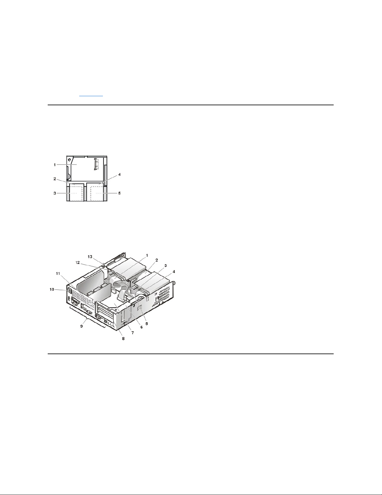
Internal Views
Figure 1 shows a top view of the chassis to help you orient yourself when you work inside the computer.
Figure 1. Orientation View
Figure 2 shows the chassis with the cover removed.
Figure 2. Inside the Chassis
Computer Cover
Figure 3. Computer Cover Removal
possible damage to the system board.
4. Wear a wrist grounding strap, and clip it to an unpainted metal surface, such as the padlock loop on the back of the chassis. If a wrist
grounding strap is not available, touch any unpainted metal surface on the back of the computer or on the computer chassis, such as
thepowersupply,todischargeanystaticchargefromyourbodybeforetouchinganythinginsidethecomputer.Whileyouwork,
periodically touch an unpainted metal surface on the computer chassis to dissipate any static electricity that might harm internal
components. Also avoid touching components or contacts on a card and avoid touching pins on a chip.
5. Verify that the auxiliary power indicator on the riser board is not on. If it is on, you may need to wait 10 to 30 seconds for it to go out
(see Riser Board).
1
System board
2
Diskette drive
3
Hard-disk drive
4
CD-ROM drive
5
Power supply
1
CD-ROM drive interface cable
2
Externally accessible upper drive bay
3
Hard-disk drive
4
Diskette-drive interface cable
5
Hard-disk drive interface cable
6
Expansion-card cage
7
System board
8
Expansion-card slots
9
I/O ports and connectors
10
AC power receptacle
11
Security cable slot
12
Power supply
13
Chassis intrusion switch
Page 63

To remove the computer cover, perform the following steps:
1. Press in to retract the padlock ring into the cover to open (see Figure 3).
2. Pressinonthetwosecuringbuttonsuntilthecoverisfreetoswingup(seeFigure3).
3. Raisethebackofthecover,andpivotittowardthefrontofthecomputer.
4. Lift the cover off the hooks at the front of the chassis.
5. Disengage the tabs that secure the cover to the top of the chassis, and lift the cover away.
Figure 4. Computer Cover Replacement
To replace the computer cover, perform the following steps:
1. Face the front of the computer and hold the cover at a slight angle (see Figure 4).
2. Align the bottom of the cover with the bottom of the chassis and insert the hooks on the cover into the recessed slots on the computer
chassis so that the tabs catch the hooks inside the slots.
3. Pivot the cover down toward the back of the chassis and into position.
Make sure that the securing buttons click into place.
4. If you wish to install a padlock, slide the padlock ring out of the cover.
To reset the chassis intrusion detector, perform the following steps:
1. Reconnect all cables to their connectors at the back of the computer.
2. Restart the system.
3. Enter System Setup. To do this, press <F2> when F2=Setup appears in the upper-right corner of the screen.
If the operating system begins to load into memory, allow the system to complete the load operation, shut down the system, and try again.
4. Restore the system configuration settings.
1Padlock ring
2Securing buttons (2)
Page 64

5. While in System Setup, perform the following steps to configure the system if it has an LS-120 SuperDisk drive:
a. Set Diskette Drive A and Diskette Drive B to Not Installed.
b. Set Secondary Drive 0 or Secondary Drive 1, as appropriate, to Auto.
c. Go to the second page and set Diskette to Off.
6. While in System Setup, reset the chassis intrusion detector under the System Security tab by changing Chassis Intrusionto Enabled,
Enabled-Silent, or Disabled.
7. If no other changes are required in System Setup, press <Esc> and follow the menu directions to restart the system and implement the
changes.
8. Run the Dell Diagnostics to verify that the system is operating correctly.
Eject and Power Buttons
Figure 5. Eject and Power Button Removal
To remove the eject and power buttons, perform the following steps:
1. Lay the computer cover on a flat work surface, with the inside of the top cover facing up.
2. To remove the 3.5-inch diskette-drive eject button, pull gently on the plastic part of the button until it comes free.
3. Toremovethepowerbutton,useasmallscrewdriverandpushinthetwoplasticclipsthatholdthebuttontothebezel.Whentheseclipsare
released, the button and the spring come free from the bezel.
Control Panel
Figure 6. Control Panel Removal
To remove the control panel, perform the following steps:
1. Remove the drive shelf.
2. Remove the power supply.
NOTE: If the system does not have an audio expansion card but does have an integrated audio controller, be sure that the
Sound setting is On. If the system has an audio expansion card, be sure that the Sound setting is Off.
1
Diskette eject button
2
Power button
1
Screw
2
Control panel
Page 65

3. Disconnect the control panel cable from the control panel connector on the system board (see "System Board Labels" for the location of the
PANEL connector).
Note the routing of the control panel cable as you remove it from the chassis.
4. Remove the mounting screw that secures the control panel to the chassis.
5. Disconnect the chassis intrusion switch cable connector from the control panel.
6. Remove the control panel cable.
7. Remove the control panel from the chassis.
Note the routing of the control panel cable as you remove it from the chassis.
When you install the replacement control panel, be sure to put the right side of the control panel behind the mounting tab.
Chassis Intrusion Switch
Figure 7. Chassis Intrusion Switch Removal
To remove the chassis intrusion switch, perform the following steps:
1. Remove the drive shelf.
2. Remove the power supply.
3. Remove the control panel.
4. Disconnect the chassis intrusion switch cable connector from the control panel.
Note the routing of the chassis intrusion cable as you remove the cable from the chassis. Chassis hooks may hold the cable in place inside
the chassis.
5. Slide the chassis intrusion switch out of its slot and remove the switch and its attached cable from the chassis.
6. Install the replacement chassis intrusion switch and cable.
7. Replace the computer cover and reset the chassis intrusion detector.
Drives
Figure 8. Drive Locations
1
Control panel
2
Chassis intrusion switch
NOTE: In all of the following procedures, left and right refer to your left and right as you face the front of the computer.
Page 66

Preliminary Steps
You must remove the drive shelf before removing the 3.5-inch diskette drive, the CD-ROM drive, the hard-disk drive, the control panel, the chassis
intrusion switch, or the power supply.
Figure 9. Drive Shelf Removal
To remove the drive shelf from the chassis, perform the following steps:
1. Disconnect the power and interface cables from the diskette drive and CD-ROM drive.
2. Press inward on the two drive shelf release tabs, and pull the shelf forward and out of the chassis (see Figure 9).
Hard-Disk Drive
Figure 10. Hard-Disk Drive/Bracket Removal
To remove the hard-disk drive and its bracket from the chassis, perform the following steps:
1
Chassis intrusion switch
2
CD-ROM drive
3
3.5-inch diskette drive
4
Hard-disk drive
1
Drive shelf
2
Release tabs (2)
1
Drive bracket
2
Release tabs (2)
CAUTION: To avoid the possibility of electric shock, turn off the computer and any peripherals, disconnect them from
electrical outlets, and then wait at least 5 seconds before you remove the computer cover. Also, before you remove a drive,
see the other precautions in "Precautionary Measures."
NOTE: This procedure assumes that you have removed the drive shelf from the chassis.
Page 67

1. If you are replacing a hard-disk drive that contains data you want to keep, make a backup copy of your files before you continue this
procedure.
2. Remove the computer cover if not already removed.
3. Remove the drive shelf.
4. Squeeze the tabs on each side of the hard-disk drive/bracket, and pull the hard-disk drive/bracket forward about one inch (see Figure 10).
5. Disconnect the power and interface cables from the back of the drive.
6. Lift the hard-disk drive/bracket away from the chassis.
7. Lay the hard-disk drive/bracket on an antistatic surface with its bracket facing up.
8. Remove the four screws securing the hard-diskdrivetothebottomofthebracket(seeFigure11).
Figure 11. Drive Bracket Removal
Figure 12. Hard-Disk Drive/Bracket Replacement
To install a replacement hard-disk drive in the chassis, perform the following steps.
NOTICE: To avoid possibly damaging the drive by ESD, ground yourself by touching an unpainted metal surface on the back of the
computer.
NOTICE: When you unpack the drive, do not set it on a hard surface, which may damage the drive. Instead, set the drive on a
surface, such as a foam pad, that will sufficiently cushion it.
1. Prepare the drive for installation.
Check the documentation for the drive to verify that it is configured for your computer system.
2. If not already done, remove the computer cover.
1
Drive2Drive bracket
3
Screws (4)
1
Tabs on bottom of drive bracket
2
Hooks on chassis floor
3
Drive bracket
4
Release tabs (2)
CAUTION: To avoid the possibility of electric shock, turn off the computer and any peripherals, disconnect them from
electrical outlets, and then wait at least 5 seconds before you remove the computer cover. Also, before you install a drive, see
the other precautions in "Precautionary Measures."
Page 68
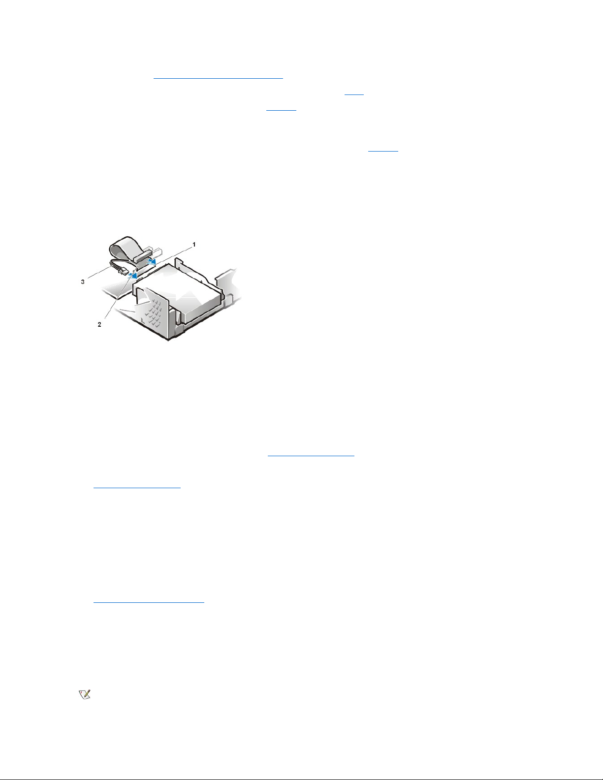
3. If not already done, remove the drive bracket from the chassis.
4. Attach the new hard-disk drive to the bracket with the four screws you removed in step 8 of the previous procedure.
5. Reinstall the hard-disk drive/bracket in the chassis (see Figure 12).
6. Place the bracket so that the release tabs extend about one inch past the front of the chassis, and align the tabs on the bottom of the bracket
with the hooks on the chassis floor.
7. Slide the bracket toward the back of the chassis until the tabs snap under the hooks (see Figure 12). The bracket release tabs should also
snap into the front of the chassis.
8. Connect a power cable to the power input connector on the back of the drive, and connect an EIDE cable to the interface connector on the
back of the drive (see Figure 13).
Check all connectors to be certain that they are properly cabled and firmly seated.
Figure 13. Hard-Disk Drive Cable Attachment
NOTICE: You must connect the blue connector on the EIDE interface cable to the IDE1 connector on the system board to avoid
possible damage to your system.
NOTICE: You must match the red-colored stripe on the EIDE cable with pin 1 on the drive's interface connector to avoid possible
damage to your system.
NOTICE: You must match the red-colored stripe on the EIDE interface cable with pin 1 on the IDE1 connector to avoid possible
damage to your system.
9. If it is not already connected, connect the blue connector on the EIDE interface cable to the IDE1 connector on the system board.
To locate the IDE1 connector on the system board, see "System Board Components."
10. Replace the drive shelf and connect the diskette and CD-ROM drive power and interface cables.
11. Replace the computer cover. Then reconnect your computer and peripherals to their electrical outlets, and turn them on.
12. Insert a bootable diskette into drive A.
13. Turn on the computer system.
14. Enter System Setup and update Primary Drive 0 (see the online System User's Guide for complete information on System Setup).
After you update the System Setup settings, reboot the system.
15. Partition and logically format your computer's hard-disk drive before proceeding to the next step.
See the documentation for your operating system for instructions.
16. Reset the chassis intrusion detector.
17. Test the hard-disk drive by running the Dell Diagnostics (see the online System User's Guide for complete information).
18. If the drive you just installed is the primary drive, install your operating system on the hard-disk drive.
For instructions, refer to the documentation that came with your operating system.
3.5-Inch Diskette Drive
To remove the 3.5-inch diskette drive from the drive shelf, perform the following steps.
1
IDE1 connector
2
EIDE cable
3
Power cable
NOTE: This procedure assumes that you have removed the drive shelf from the chassis.
Page 69

1. Press down on the release latch on the top left side of the 3.5-inch diskette drive.
The 3.5-inch diskette drive will pop up slightly when the latch disengages.
2. Pivot the 3.5-inch diskette drive up and out of the drive shelf.
To replace the 3.5-inch diskette drive, perform the following steps:
1. Rotate the replacement drive into position under the right diskette drive bracket on the drive shelf.
2. Lower the left side of the diskette drive while gently pressing downward, so that the slots on the bottom of the 3.5-inch diskette drive engage
in hooks on the drive shelf.
3. Ensure that the latch on the left side of the 3.5-inch diskette drive engages the top of the diskette drive.
If necessary, press on the latch from the bottom of the drive shelf.
4. Replace the drive shelf and connect the interface and power cable connectors.
CD-ROM Drive
Figure 14. CD-ROM Drive Removal
To remove a CD-ROM drive, perform the following steps.
1. Pushdownonthedrivereleasetabontherightsideofthedrive(seeFigure14).
2. Slide the CD-ROM drive assembly forward and up and out of the chassis.
To replace a CD-ROM drive, perform the following steps:
1. Align the tabs on the bottom of the CD-ROM drive with the notches on the drive shelf, and slide the drive toward the back of the shelf until it
snaps into place (see Figure 15).
Figure 15. CD-ROM Drive Replacement
2. Connect a power cable and an interface cable to the appropriate connectors on the back of the drive (see Figure 16).
Figure 16. CD-ROM Drive Cable Attachment
1
Drive release tab
NOTE: This procedure assumes that you have removed the drive shelf from the chassis.
1
Tabs (2)
2
Notches (2)
Page 70

Check all cable connections. Fold cables out of the way to provide airflow for the fan and cooling vents.
3. Replace the computer cover; reconnect your computer and peripherals to their electrical outlets, and turn them on.
4. Enter System Setup to update your system configuration information.
Set the Drive 1 option under Drives: Primary to Auto. See the online System User's Guide for more information.
5. Reset the chassis intrusion detector.
System Power Supply
Figure 17. Power Supply Removal
To remove the system power supply, perform the following steps:
1. Disconnect the AC power cable from the back of the power supply.
2. DisconnecttheDCpowercablesfromthesystemboardandthedrives.
3. Remove the screw on the side of the chassis that secures the power supply.
4. RemovethescrewbelowtheACpowerreceptacleatthebackofthechassis.
5. Slide the power supply toward the center of the computer approximately 1 inch.
6. Liftthepowersupplyupandoutofthecomputerchassis.
Expansion-Card Cage
Figure 18. Expansion-Card Cage Removal
1
Interface cable
2
Power cable
3
Power input connector
4
Interface connector
1
Securing screw hole
2
AC power receptacle
3
Power supply
4
System board DC power connectors (2)
5
Drive DC power connectors (3)
Page 71
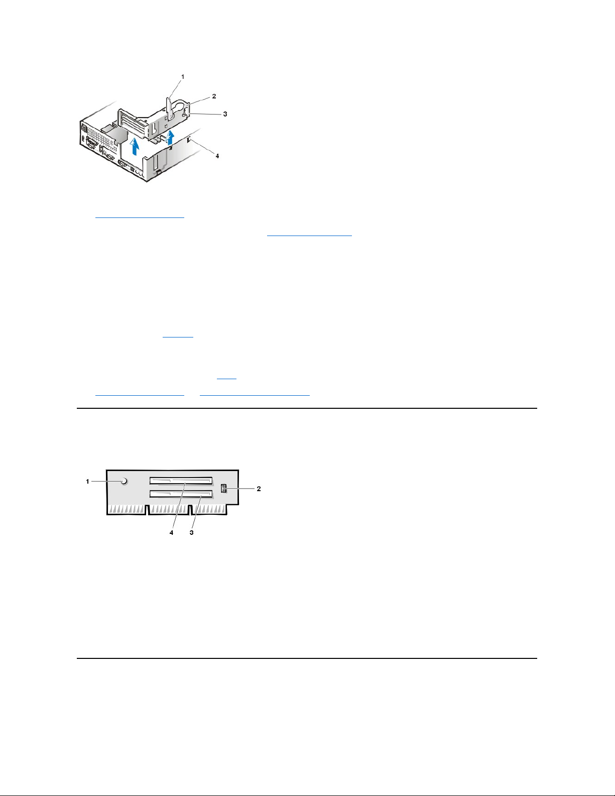
To remove the expansion-card cage from the chassis, perform the following steps:
1. Remove the computer cover.
2. Examine the cables connected to expansion cards through the back-panel openings, and disconnect any cables that will not reach to where
the cage must be placed when it is removed from the chassis.
3. Locate the securing lever and rotate the lever upward until it stops in an upright position.
4. Lift the expansion-card cage up and out of the chassis.
To replace the expansion-card cage into the chassis, perform the following steps:
1. With the securing lever in the upright position, align the tabs in the side of the expansion-card cage with the mating hooks on the left side of
the chassis wall (see Figure 18). Slide the expansion-card cage into place.
2. Rotate the securing lever downward until it is flush with the top side of the chassis. Make sure that the riser board is fully seated in the RISER
connector on the system board.
3. Reconnect any cables you removed in step 2 of the previous procedure.
4. Replace the computer cover and reset the chassis intrusion detector.
Riser Board
Figure 19. PCI Riser Board
The chassis has a PCI riser board that has two PCI expansion-card connectors (see Figure 19).
To remove the PCI riser board, perform the following steps:
1. Remove the expansion-card cage.
2. Remove the expansion cards installed in the slots.
3. Remove the screws securing the riser board to the expansion-card cage.
4. Lift the riser board off the expansion-card cage.
System Board Components
Figure 20 shows the system board and the location of all its sockets and connectors.
Figure 20. System Board Components
1
Securing lever
2
Expansion-card cage
3
Tabs (2)
4
Hooks (2)
NOTICE: Use a wrist grounding strap as explained in "Precautionary Measures."
1
Auxiliary power indicator LED (AUX_LED)
2
Wakeup On LAN jumper (WOL)
3
PCI expansion slot 1 (PCI1)
4
PCI expansion slot 2 (PCI2)
Page 72

System Board Jumpers
Figure 21 shows the location of the jumpers on the system board. Table 1 lists the system board jumpers and their settings.
Figure 21. System Board Jumpers
1
Line-in connector
2
Line-out connector
3
Microphone connector
4
NIC connector
5
Video connector
6
Serial port 2 connector
7
USB connectors (2)
8
Keyboard (lower) and mouse (upper) connectors
9
Parallel port (upper) and serial port 1 (lower) connectors
10
Microprocessor connector
11
RIMM sockets (2)
12
DC power 1 connector
13
DC power 2 connector
14
Chassis intrusion connector
15
Control panel connector
16
External speaker connector
17
EIDE1 connector
18
EIDE2 connector
19
System board speaker
20
System board jumpers
21
Diskette/tape-drive connector
22
Riser board connector
23
Real-time clock reset (RTCRST) jumper
24
Battery
25
Modem audio connector
26
Fan connector
27
CD audio cable connector
Page 73

Jumpers are small blocks on a circuit board with two or more pins emerging from them. Plastic plugs containing a wire fit down over the pins. The
wire connects the pins and creates a circuit.
NOTICE: Make sure your system is turned off before you change a jumper setting. Otherwise, damage to your system or
unpredictable results may occur.
To change a jumper setting, pull the plug off its pin(s) and carefully fit it down onto the pin(s) indicated.
Table 1. System-Board Jumper Settings
System Board Labels
Table 2 lists the labels for connectors and sockets on your system board, and it gives a brief description of their functions.
Table 2. System Board Connectors and Sockets
Jumper
Setting
Description
PSWD
(default)
Password features are enabled.
(default)
Password features are disabled.
SAFE
(default)
Reserved (do not change).
BIOS
(default)
Reserved (do not change).
RTCRST
(default)
Real-time clock reset. Can be used for troubleshooting purposes.
jumpered unjumpered
Connector or Socket
Description
AMC
ATI multimedia channel connector
BATTERY
Battery socket
CD_IN
CD-ROM audio interface connector
RIMM_x
RIMM socket
DSKT
Diskette/tape drive interface connector
ENET
Integrated NIC connector
EXT_SPKR
External speaker connector
FAN
Microprocessor fan connector
HDLED
Hard-disk drive LED connector
IDEn
EIDE interface connector
INTRUDER
Chassis intrusion switch connector
KYBD
Keyboard connector
MODEM
Modem audio connector
MONITOR
Video connector
Page 74

Expansion Cards
The small form-factor GX200 chassis can accommodate up to two half-length 32-bit PCI expansion cards. Figure 22 shows an example of a 32-bit
PCI expansion card.
Figure 22. 32-Bit PCI Expansion Card Example
Expansion Card Removal
To remove an expansion card, perform the following steps:
1. Remove the computer cover.
2. If necessary, disconnect any cables connected to the card.
3. Remove the expansion-card cage.
4. Remove the screw on the mounting bracket of the card you want to remove.
5. Grasp the card by its outside corners, and ease it out of its connector.
6. If you are removing the card permanently, install a metal filler bracket over the empty card-slot opening.
7. Replace the computer cover, and reconnect your computer and peripherals to their electrical outlets and turn them on.
8. Reset the chassis intrusion detector.
Figure 23. Expansion Card Installation
MOUSE
Mouse connector
PANEL
Control panel connector
PARALLEL
Parallel port connector; sometimes referred to as LPT1
PCIn*
PCI expansion-card connector
POWER_1
Main power input connector
POWER_2
3.3-V power input connector
RISER
Riser board connector
SERIALn
Serial port connector
SLOT1_PRI
Primary microprocessor connector
USB
USB connectors
NOTE: Installing filler brackets over empty card-slot openings is necessary to maintain Federal Communications Commission (FCC)
certification of the system. The brackets also keep dust and dirt out of your computer.
Page 75

To install an expansion card, perform the following steps:
1. Prepare the expansion card for installation, and remove the computer cover.
See the documentation that came with the expansion card for information on configuring the card, making internal connections, or otherwise
customizing it for your system.
2. Remove the screw and remove the metal filler bracket that covers the card-slot opening for the expansion slot you intend to use (see Figure
24).
Save the screw to use when installing the expansion card later in this procedure.
Figure 24. Filler Bracket Removal
3. Insert the expansion card into the expansion-card connector.
If the expansion card is full-length, insert the front end of the card into the corresponding card guide on the inside front of the chassis as you
insert the card into its connector. Insert the card's edge connector firmly into the expansion-card slot.
4. When the card is firmly seated in the connector, secure the card's mounting bracket to the chassis with the screw you removed in step 2.
5. Connect any cables that should be attached to the card.
See the documentation for the card for information about the card's cable connections.
6. Replace the computer cover.
7. Reset the chassis intrusion detector.
Memory
To remove a Rambus in-line memory module (RIMM), perform the following steps:
1. Remove the computer cover.
2. Remove the system power supply to allow you to access the RIMMs.
3. Press the securing clips outward simultaneously until the RIMM disengages and pops out slightly from the socket (see Figure 25).
Figure 25. RIMM Removal
1
Expansion card
2
Card-edge connector
3
Riser board
4
Expansion-card connector
5
Expansion-card cage
CAUTION: Some network cards automatically start up the system when they are connected. To
guard against electric shock, be sure to unplug your computer from its electrical outlet before
installing any expansion cards.
1
Filler bracket
Page 76
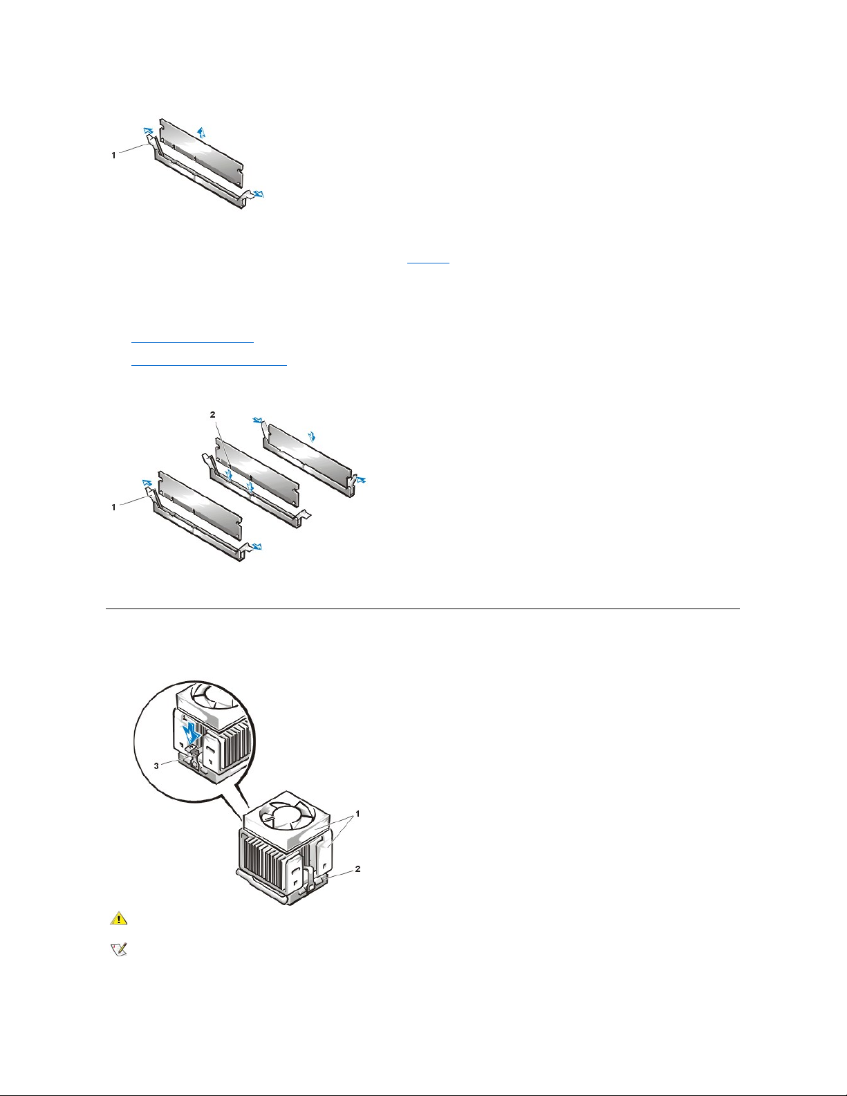
To reinstall a RIMM, perform the following steps:
1. Locate the plastic securing clips at each end of the socket (see Figure 26).
2. Press the clips outward until they snap open.
3. Press the RIMM straight into the slot running down the center of the socket until the securing tabs snap into place around the ends of the
RIMM.
4. Replace the computer cover.
5. Reset the chassis intrusion detector.
Figure 26. RIMM Installation
6. Run the Dell Diagnostics to verify that the RIMMs are operating properly.
Microprocessor/Cooling Fan/Heat Sink Assembly
Figure 27. Microprocessor/Cooling Fan/Heat Sink Assembly
To replace a microprocessor, perform the following steps:
1
Securing clips (2)
1
Securing clips (2)
2
Notches (2)
1
Cooling fan/heat sink assembly
2
ZIF socket
3
Retaining clip
CAUTION: The microprocessor/heat sink assembly can get extremely hot. Be sure that the assembly has had sufficient time to
cool before you touch it.
NOTE: Dell recommends that only a technically knowledgeable person perform this procedure.
Page 77

1. Remove the computer cover.
2. Disconnect the cooling fan power cable from its system board connector.
3. Remove the metal retaining clip that secures the cooling fan/heat sink assembly to the microprocessor package by gently pushing down on
the folded part of the retaining clip with a small screwdriver.
The retaining clip hooks over the sides of the zero insertion force (ZIF) socket.
4. Remove the heat sink assembly from the microprocessor package.
NOTICE: Be careful not to bend any of the pins when you remove the microprocessor package from the ZIF socket. Bending
the pins can permanently damage the microprocessor.
5. Detach and lift the microprocessor package away from the ZIF socket.
The ZIF socket has a lever-type handle that secures and releases the microprocessor package from the ZIF socket.
a. Pull the socket release lever straight out until the microprocessor package is released.
b. Remove the microprocessor package from the socket.
Leave the release lever extended so that the socket is ready for the new microprocessor.
Figure 28. Microprocessor Package Removal
6. Unpack the new microprocessor package.
If any of the pins on the new microprocessor appear to be bent, return the microprocessor package.
NOTICE: You must position the microprocessor package correctly in the ZIF socket to avoid permanent damage to the
microprocessor and the computer when you turn on the system.
7. Install the microprocessor package in the ZIF socket.
a. If the release lever on the ZIF socket is not all the way out, move it to that position.
b. Align pin-1 (the beveled corner) of the microprocessor package and pin-1 of the ZIF socket.
c. Set the microprocessor package lightly in the socket, making sure that all the pins are headed into the correct holes.
Because the system uses a ZIF socket, there is no need to use force (which could bend the pins if the microprocessor package is
misaligned).
d. When the microprocessor package is positioned correctly, press it with minimal pressure to fully seat it in the ZIF socket.
e. When the microprocessor package is fully seated, pivot the release lever back toward the system board until it snaps into place,
securing the microprocessor package.
Figure 29. Microprocessor Package Installation
8. Unpack the cooling fan/heat sink assembly included in the replacement kit.
1
Microprocessor package
2
Socket release lever
3
ZIF socket
1
Microprocessor
2
ZIF socket
3
Pin-1 (beveled corner)
Page 78

NOTICE: Do not reuse the old heat sink assembly when you replace the microprocessor package. Using the old heat sink
assembly can cause the microprocessor to overheat because there is not enough thermal compound between the old heat
sink assembly and the microprocessor package.
9. Replace the heat sink assembly.
a. Peel the release liner from the adhesive tape attached to the bottom of the new heat sink assembly.
b. Place the heat sink assembly on top of the microprocessor package.
c. Orient the metal retaining clip and hook the unhinged end of the clip over the tab on the top edge of the ZIF socket.
d. Press down on the hinged end of the clip to snap the clip over the tab on the bottom edge of the ZIF socket.
10. Reconnect the cooling fan power cable to its system board connector.
11. Replace the computer cover and restart the system.
12. Enter System Setup and confirm that the system data area correctly identifies the type of microprocessor installed.
13. Reset the chassis intrusion detector. While in System Setup, confirm that the system data area correctly identifies the type of microprocessor
installed.
System Battery
Figure 30. System Battery Removal
To remove the system battery, perform the following steps:
1. If possible, enter System Setup and print the System Setup screens.
2. Remove the system battery by carefully prying it out of its socket with your fingers or with a blunt, nonconducting object such as a plastic
screwdriver.
When you replace the system battery, orient the new battery with the "+" facing up. Insert the battery into its socket and snap it into place.
System Board
Figure 31. System Board Removal
1
Battery
2
Battery socket
CAUTION: There is a danger of the new battery exploding if it is incorrectly installed. Replace the battery only with the same or
equivalent type recommended by the manufacturer. Discard used batteries according to the manufacturer’s instructions.
Page 79

To remove the system board, perform the following steps:
1. Disconnect all cables from their connectors at the back of the computer.
2. Remove the drive shelf assembly.
3. Remove the expansion-card cage.
4. Remove the hard-disk drive/bracket.
5. Disconnect all cables from the system board.
6. Remove the screw that secures the system board to the bottom of the chassis (see Figure31).
7. Slide the system board toward the front of the chassis until it stops.
8. Carefully lift the system board out of the chassis (be sure to lift evenly and not twist the system board).
To install a new system board, perform the following steps:
1. Remove the RIMMs and the microprocessor/cooling fan/heat sink assembly and install them on the replacement board.
2. Set the jumpers on the new system board so that they are identical to those on the old board, unless a microprocessor upgrade is being
installed.
3. Push down near each slot to engage the grounding clip onto its corresponding tab.
4. Push evenly on both sides of the system board as you slide it into position (do not twist the system board).
5. Replace the screw that secures the system board to the bottom of the chassis.
6. Reconnect all cables to the system board.
7. Replace the hard-disk drive/bracket.
8. Replace the expansion-card cage.
9. Replace the drive shelf assembly.
10. Replace the computer cover.
11. Reset the chassis intrusion detector. While in System Setup, confirm that the system data area correctly identifies the type of microprocessor
installed.
Back to Contents Page
1
Systemboard
2
Screw
 Loading...