

Page 1
Contents: Dell OptiPlex GX1 Small-Form-Factor System User's Guide
Dell™ OptiPlex™ GX1 Small-Form-Factor System User's Guide
Introduction
Setup and Operation
Using the System Setup Program
Installing Upgrades
Troubleshooting
Specifications
NOTE: You can obtain the latest version of this document from the Dell Web support site at
http://support.dell.com
.
Model DCP
Notes, Notices, and Cautions
Throughout this guide, there may be blocks of text printed in bold type or in italic type. These blocks are
notes, notices, and cautions, and they are used as follows:
NOTE: A NOTE indicates important information that helps you make better use of your system.
NOTICE: A NOTICE indicates either potential damage to hardware or loss of data and tells you how
to avoid the problem.
CAUTION: A CAUTION indicates a potentially hazardous situation which, if not avoided, may
result in minor or moderate injury.
Information in this document is subject to change without notice.
© 1999–2000 Dell Computer Corporation. All rights reserved.
Reproduction in any manner whatsoever without the written permission of Dell Computer Corporation is strictly forbidden.
Trademarks used in this text: Dell, OptiPlex, Dimension , Inspiron, Latitude, DellWare , Dell OpenManage, and the DELL logo are
trademarks of Dell Computer Corporation; Intel, Pentium, and LANDesk are registered trademarks and MMX is a trademark of Intel
Corporation; Microsoft, MS-DOS, Windows, Windows NT , and DirectX are registered trademarks and Windows for Workgroups is a
trademark of Microsoft Corporation; IBM and OS/2 are registered trademarks of International Business Machines Corporation; 3Com
is a registered trademark of 3Com Corporation; VESA is a registered trademark of Video Electronics Standards Association. As an
ENERGY STAR Partner, Dell Computer Corporation has determined that this product meets the ENERGY STAR guidelines for
energy efficiency.
file:///C|/infodev/2013/eDoc/OpGX1/UG/index.htm[2/21/2013 11:47:08 AM]
Page 2

Contents: Dell OptiPlex GX1 Small-Form-Factor System User's Guide
Other trademarks and trade names may be used in this document to refer to either the entities claiming the marks and names or
their products. Dell Computer Corporation disclaims any proprietary interest in trademarks and trade names other than its own.
Initial release: 9 Jun 1999
Last revised: 17 Feb 2000
file:///C|/infodev/2013/eDoc/OpGX1/UG/index.htm[2/21/2013 11:47:08 AM]
Page 3
Introduction: Dell OptiPlex GX1 Small-Form-Factor System User's Guide
Back to Contents Page
Introduction: Dell™ OptiPlex™ GX1 Small-Form-Factor System
User's Guide
Overview Manageability Features
System Features Security Features
Hardware Features ENERGY STAR® Compliance
Software Features
Overview
Dell OptiPlex GX1 small-form-factor systems are high-speed, expandable personal computers designed
around the Intel® Pentium® II or III microprocessor. Each computer system uses a high-performance
Peripheral Component Interconnect (PCI) design that allows you to configure the computer system to your
initial requirements and then add Dell-supported upgrades as necessary.
System Features
Your system offers the following features:
An Intel Pentium II or Pentium III microprocessor.
The Intel Pentium II and Pentium III microprocessors include MMX™ technology designed to handle
complex multimedia and communications software. This microprocessor incorporates new instructions
and data types as well as a technique called single instruction, multiple data (SIMD) that allows the
microprocessor to process multiple data elements in parallel, thereby improving overall system
performance.
A keyboard command (<Ctrl><Alt><\>) that lets you switch between the microprocessor's rated speed
and a slower compatibility speed.
NOTE: This keyboard command is not available under the Microsoft® Windows NT® and
IBM® OS/2® operating systems.
A secondary cache of 512 KB of static random-access memory (SRAM) included within the single-edge
contact (SEC) cartridge, which also contains the microprocessor.
System memory that can be increased up to 768 megabytes (MB) by installing 32-, 64-, 128-, or 256MB synchronous dynamic RAM (SDRAM) dual in-line memory modules (DIMMs) in the three DIMM
sockets on the system board. The system also supports both error checking and correction (ECC) and
nonparity DIMMs. See "System Memory
file:///C|/infodev/2013/eDoc/OpGX1/UG/intro.htm[2/21/2013 11:47:09 AM]
" for details.
Page 4

Introduction: Dell OptiPlex GX1 Small-Form-Factor System User's Guide
Self-Monitoring and Analysis Reporting Technology II (SMART II) support, which warns you at system
start-up if your hard-disk drive has become unreliable. To take advantage of this technology, you must
have a SMART II-compliant hard-disk drive in your computer. All hard-disk drives shipped with
OptiPlex GX1 systems are SMART II-compliant.
A basic input/output system (BIOS), which resides in flash memory and can be upgraded by diskette or
remotely over a network, if required.
Full compliance with PCI specification 2.1.
Full Plug and Play version 1.0a capability, which greatly simplifies the installation of expansion cards.
Plug and Play support included in the system BIOS allows you to install Plug and Play expansion cards
without setting jumpers or switches or performing other configuration tasks. Also, because the system
BIOS is stored in flash memory, it can be updated to support future enhancements to the Plug and Play
standard.
Wakeup On LAN capability, which, when enabled in the System Setup program, allows the system to
be turned on from a server management console. Wakeup On LAN capability also allows remote
computer setup, software downloading and installation, file updates, and asset tracking after hours and
on weekends when network traffic is at a minimum.
Universal Serial Bus (USB) capability, which can simplify connecting peripheral devices such as mice,
printers, and computer speakers. The USB connectors on your computer's back panel, which are
enabled by default, provide a single connection point for multiple USB-compliant devices. USBcompliant devices can also be connected and disconnected while the system is running.
A modular computer chassis with a minimum number of screws for easy disassembly and improved
serviceability.
Hardware Features
The system board includes the following integrated features:
Two 32-bit PCI expansion slots on a riser board (half-length PCI expansion cards only).
A 64-bit accelerated graphics port (AGP) video subsystem, which includes the ATI 3D Rage Pro super
video graphics array (SVGA) video controller. This video subsystem contains 4 MB (upgradable to 8
MB) of synchronous graphics RAM (SGRAM) video memory. Maximum resolutions are 1600 x 1200
with 65,536 colors noninterlaced and 1280 x 1024 and 1024 x 768 with true-colors noninterlaced. In
800 x 600 and 640 x 480 resolutions, 16.7 million colors are available for true-color graphics using a
32-bits per pixel (bpp) format. True-color provides higher performance, but uses more graphics
memory. Table 1 lists the video memory requirements for the Microsoft Windows® 95 and Windows NT
4.0 operating systems.
Table 1. Video Memory Requirements
Video
Resolution
640 x 480 True-Color
Maximum Color
Depth
Maximum
Refresh Rate
85 hertz (Hz) 4 MB
(32 bpp)
file:///C|/infodev/2013/eDoc/OpGX1/UG/intro.htm[2/21/2013 11:47:09 AM]
Maximum SGRAM
Required
Page 5

Introduction: Dell OptiPlex GX1 Small-Form-Factor System User's Guide
800 x 600 True-color
85 Hz 4 MB
simultaneously). For more information, see the Dell ResourceCD.
(32 bpp)
1024 x 768 True-color
(32 bpp)
1280 x 1024 True-color
(32 bpp)
1600 x 1200 65,536 colors
(16 bpp)
2X AGP provides a dedicated bus from the video subsystem to the system chip set. AGP-based video
subsystems have two significant performance advantages over PCI-based video subsystems:
— The AGP bus reduces bandwidth requirements of the PCI bus, improving overall system
performance.
— The AGP bus allows a 3D video subsystem to execute directly from main memory.
A diskette interface, which supports a 3.5-inch diskette drive.
Enhanced integrated drive electronics (EIDE) support. The primary and secondary interface are both
located on the PCI bus to provide faster data throughput. Each interface supports high-capacity EIDE
drives, as well as devices such as ATA 33 hard-disk drives and EIDE CD-ROM drives.
85 Hz 4 MB
75 Hz 8 MB
75 Hz 8 MB
Two high-performance serial ports and one bidirectional parallel port for connecting external devices.
The parallel port is fully Enhanced Capabilities Port (ECP)-compliant.
A Personal System/2 (PS/2)-style keyboard port and a PS/2-compatible mouse port.
An optional integrated, 10/100-megabit-per-second (Mbps) 3Com® PCI 3C905B-TX Ethernet network
interface controller (NIC). The NIC is configured using software on the Dell ResourceCD.
A 16-bit, integrated Plug and Play Crystal CS4236B audio controller that provides all the sound
functions of the Sound Blaster Pro expansion card. For more information, see the Dell ResourceCD.
Software Features
The following software is included with your Dell computer system:
System utilities that safeguard your system and enhance the operation of its features. For more
information, see the Dell ResourceCD.
Video drivers for displaying many popular applications in high-resolution modes. For more information,
see the Dell ResourceCD.
Audio drivers for enabling the sound functions on the expansion sound card. For more information, see
the Dell ResourceCD.
Bus-mastering EIDE drivers to improve performance by off-loading certain functions from the
microprocessor during multithreaded operation (when several application programs are running
file:///C|/infodev/2013/eDoc/OpGX1/UG/intro.htm[2/21/2013 11:47:09 AM]
Page 6

Introduction: Dell OptiPlex GX1 Small-Form-Factor System User's Guide
The System Setup program for quickly viewing and changing the configuration information for your
system. For more information on this program, see "System Setup Program
Enhanced security features (a setup password, a system password, a system-password lock option,
a write-protect option for diskette drives, and automatic display of the system's service tag number)
available through the System Setup program. In addition, a customer-definable asset tag number can
be assigned via a software support utility and viewed on the System Setup screen
information, see "System Setup Program
."
Advanced power management options that can reduce the energy consumption of your system. For
more information, see "System Setup Program
Dell Diagnostics for evaluating the computer's components and devices.
Network device drivers for several network operating systems. For more information, see the Dell
ResourceCD.
Desktop Management Interface (DMI) support, which enables the management of your computer
system's software and hardware. DMI defines the software, interfaces, and data files that enable your
system to determine and report information about system components.
."
. For more
."
Manageability Features
Your system incorporates many hardware and software features to improve the manageability of the system.
Installed features include:
Dell OpenManage™ program
Fault management
Configuration management
Asset management
Security management
Preboot eXecution Environment (PXE)
Wakeup On LAN
Auto Power On
Temperature monitoring
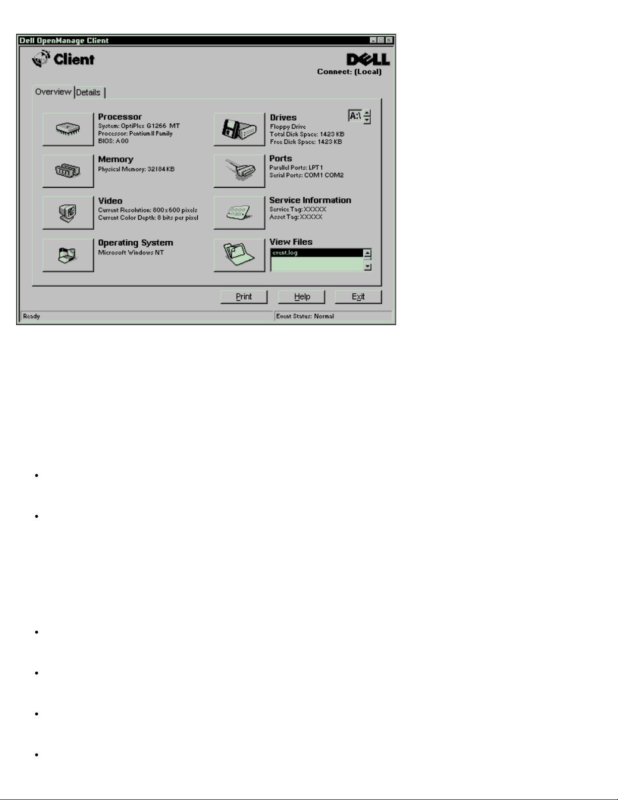
Dell OpenManage Program
The Dell OpenManage program is the Dell software-management application interface for DMI. It allows you
to manage system-level information, such as system configuration information and management information
format (MIF) database values (see Figure 1).
Figure 1. Dell OpenManage Program
file:///C|/infodev/2013/eDoc/OpGX1/UG/intro.htm[2/21/2013 11:47:09 AM]
Page 7
Introduction: Dell OptiPlex GX1 Small-Form-Factor System User's Guide
On systems running Windows 95, Windows 98, and Windows NT 4.0, the Dell OpenManage program is
available in client and administrator versions. The Dell OpenManage administrator version enables system
administrators to view, manage, and inventory remote systems in a Dell DMI client network and incorporates
the following manageability features, which are based on the DMI 2.0 specification.
Fault Management
Fault management features of Dell OpenManage include:
Alerts to warn you about events generated by SMART drives on a local or remote system and about
thermal errors
An event log that stores events in a text file and reports information about the event under the following
options: System Name, Component Name, Date and Time, Event Type, Event Severity, Event
Class, Event System
Configuration Management
Configuration management features of Dell OpenManage include:
Wakeup On LAN support, which allows network administrators to remotely turn on Managed PC
systems with Wakeup On LAN capability in a Dell DMI network.
A System Properties window that enables network administrators to view, set, or disable certain
hardware configuration settings for the local and remote systems in a Dell DMI network.
Support for the Microsoft System Management Server (SMS), which allows the exporting of one or
more groups to an SMS directory that the SMS administrator can access.
A monitor component for systems running Windows 95 that have a display data channel (DDC)-
file:///C|/infodev/2013/eDoc/OpGX1/UG/intro.htm[2/21/2013 11:47:09 AM]
Page 8

Introduction: Dell OptiPlex GX1 Small-Form-Factor System User's Guide
compliant video subsystem and monitor.
Automated inventory control of one or more groups for the remote systems in a Dell DMI network.
Network administrators can automate inventory to occur every day, week, or month at a certain hour,
on the hour; or they can enable inventory as needed. Dell OpenManage creates a text file for the
group(s) and saves it to a user-defined directory.
Support for the application program used to create user-definable attributes (UDAs).
Asset Management
Asset management features of Dell OpenManage include:
Support that enables network administrators to remotely view, enter, and modify an asset tag for a
remote system in a Dell DMI network
Automated and manual mapping of one or more groups to a user-defined directory
Security Management
Security management features of Dell OpenManage include:
Password security that enables network administrators to maintain standard attribute values for the
local and remote systems in a Dell DMI network
For more information about Dell OpenManage, refer to the online Dell OpenManage Help that accompanied
the software.
PXE
The Preboot eXecution Environment (PXE) allows a personal computer to be managed by one or more
configuration management servers running the Intel LANDesk® Configuration Manager (LCM) software,
which provides management services for the many Managed PC systems on the network. The LCM allows
network administrators to do the following:
Provide preboot support for a new Managed PC system that depends on the server for its initial
operating system installation
Service the network boot requests from the Managed PC systems
Download diagnostics and BIOS update utilities
Format the hard-disk drive, if required
Download and install the operating system, based on previously established profiles
Download and install application software
Update the operating system and applications as required
For additional information about the Intel LCM, refer to the documentation that accompanied the software.
file:///C|/infodev/2013/eDoc/OpGX1/UG/intro.htm[2/21/2013 11:47:09 AM]
Page 9

Introduction: Dell OptiPlex GX1 Small-Form-Factor System User's Guide
Wakeup On LAN
The Wakeup On LAN feature allows you to remotely turn on a Managed PC system that is in a sleep state.
The ability to turn on the Managed PC systems remotely allows you to perform remote computer setup,
software downloading and installation, file updates, and asset tracking after hours and on weekends when
users are not using the systems and network traffic is at a minimum.
To use the Wakeup On LAN feature, each Managed PC system must contain a NIC that supports Wakeup
On LAN. You must also enable the Wakeup On LAN
option in the System Setup program.
Auto Power On
Auto Power On enables you to turn on the computer system automatically on certain days of the week at a
preset time. You can set Auto Power On to turn on the system either every day or every Monday through
Friday.
NOTE: This feature does not work if the system is shut off using a power strip or surge protector.
Temperature Monitoring
Your system includes temperature probes to sense when the processor becomes overheated. In such a
case, a message appears on the screen when Dell OpenManage is running or at the next system start-up
notifying you of the problem.
Security Features
Your system has the following integrated security features.
Chassis intrusion
Security cable slot and padlock ring
Passwords
Chassis Intrusion
An integrated chassis intrusion alarm displays the status of the system chassis intrusion monitor. If the
chassis has been opened, the setting changes to Detected and the following message is displayed during
the boot sequence at system start-up:
Alert! Cover was previously removed.
The field can be cleared using the System Setup program to enable future intrusions to be detected. For
more information, see "System Setup Program
."
Security Cable Slot and Padlock Ring
The padlock ring allows you to secure the computer cover to the chassis to prevent unauthorized access to
the inside of the computer. To use the padlock ring, insert a commercially available padlock through the ring
file:///C|/infodev/2013/eDoc/OpGX1/UG/intro.htm[2/21/2013 11:47:09 AM]
Page 10

Introduction: Dell OptiPlex GX1 Small-Form-Factor System User's Guide
and then lock the padlock.
On the back of the computer are a security cable slot and padlock ring (see Figure 3 in "Setup and
Operation") for attaching commercially available antitheft devices. (The padlock ring is recessed inside the
cover.) Security cables for personal computers usually include a segment of galvanized cable with an
attached locking device and key. To prevent unauthorized removal of your computer, loop the cable around
an immovable object, insert the locking device into the security cable slot on the back of your computer, and
lock the device with the key provided. Complete instructions for installing this kind of antitheft device are
usually included with the device.
NOTES: Antitheft devices are of differing designs. Before purchasing such a device, make sure it will
work with the cable slot on your computer.
Installing a security cable with a locking device in the security cable slot also prevents unauthorized
access to the inside of the computer.
Passwords
The password feature enables you to set a user-defined password to restrict access to the system.
Additional protection is available through the System Setup program. When the Setup Password option is
set to Enabled, Password Status allows you to prevent the system password from being changed or
disabled at boot time. For more information, see "System Setup Program
."
ENERGY STAR® Compliance
Certain configurations of Dell computer systems comply with the requirements set forth by the Environmental
Protection Agency (EPA) for energy-efficient computers. If the front panel of your computer bears the
ENERGY STAR® Emblem (see Figure 2
all ENERGY STAR® power management features of the computer are enabled. To disable or change the
operation of these features, you must change the setting for the Power Management
Setup program.
NOTES:As an ENERGY STAR® Partner, Dell Computer Corporation has determined that this product
meets the ENERGY STAR® guidelines for energy efficiency.
Any Dell computer bearing the ENERGY STAR® Emblem is certified to comply with EPA ENERGY
STAR® requirements as configured when shipped by Dell. Any changes you make to this
configuration (such as installing additional expansion cards or drives) may increase the system's
power consumption beyond the limits set by the EPA's ENERGY STAR® Computers program.
Figure 2. ENERGY STAR Emblem
), your original configuration complied with these requirements and
option in the System
The EPA's ENERGY STAR® Computers program is a joint effort between the EPA and computer
file:///C|/infodev/2013/eDoc/OpGX1/UG/intro.htm[2/21/2013 11:47:09 AM]
Page 11

Introduction: Dell OptiPlex GX1 Small-Form-Factor System User's Guide
manufacturers to reduce air pollution by promoting energy-efficient computer products. The EPA estimates
that use of ENERGY STAR® computer products can save computer users up to two billion dollars annually in
electricity costs. In turn, this reduction in electricity usage can reduce emissions of carbon dioxide, the gas
primarily responsible for the greenhouse effect, and sulfur dioxide and nitrogen oxides, which are the two
primary causes of acid rain.
Computer users can also help to reduce electricity usage and its side effects by turning off their computer
systems when they are not in use for extended periods of time, particularly at night and on weekends.
Back to Contents Page
file:///C|/infodev/2013/eDoc/OpGX1/UG/intro.htm[2/21/2013 11:47:09 AM]
Page 12
Setup and Operation: Dell OptiPlex GX1 Small-Form-Factor System User's Guide
Back to Contents Page
Setup and Operation: Dell™ OptiPlex™ GX1 Small-Form-Factor
System User's Guide
Getting Started Security Cable Slot and Padlock Ring
Connecting Peripheral Devices Using the System Password Feature
Controls and Indicators Using the Setup Password Feature
Chassis Intrusion Disabling a Forgotten Password
Getting Started
If you need to set up your computer system yourself (rather than having it set up by a network administrator),
see "Getting Started" in the System Information Guide that accompanied your system for instructions on
connecting cables and turning on your system for the first time.
After you correctly connect all the cables to your system and turn it on, see the setup guide for your
operating system to complete its installation. When the operating system is installed, you can connect
peripheral devices such as a printer or install application programs not already installed by Dell.
Connecting Peripheral Devices
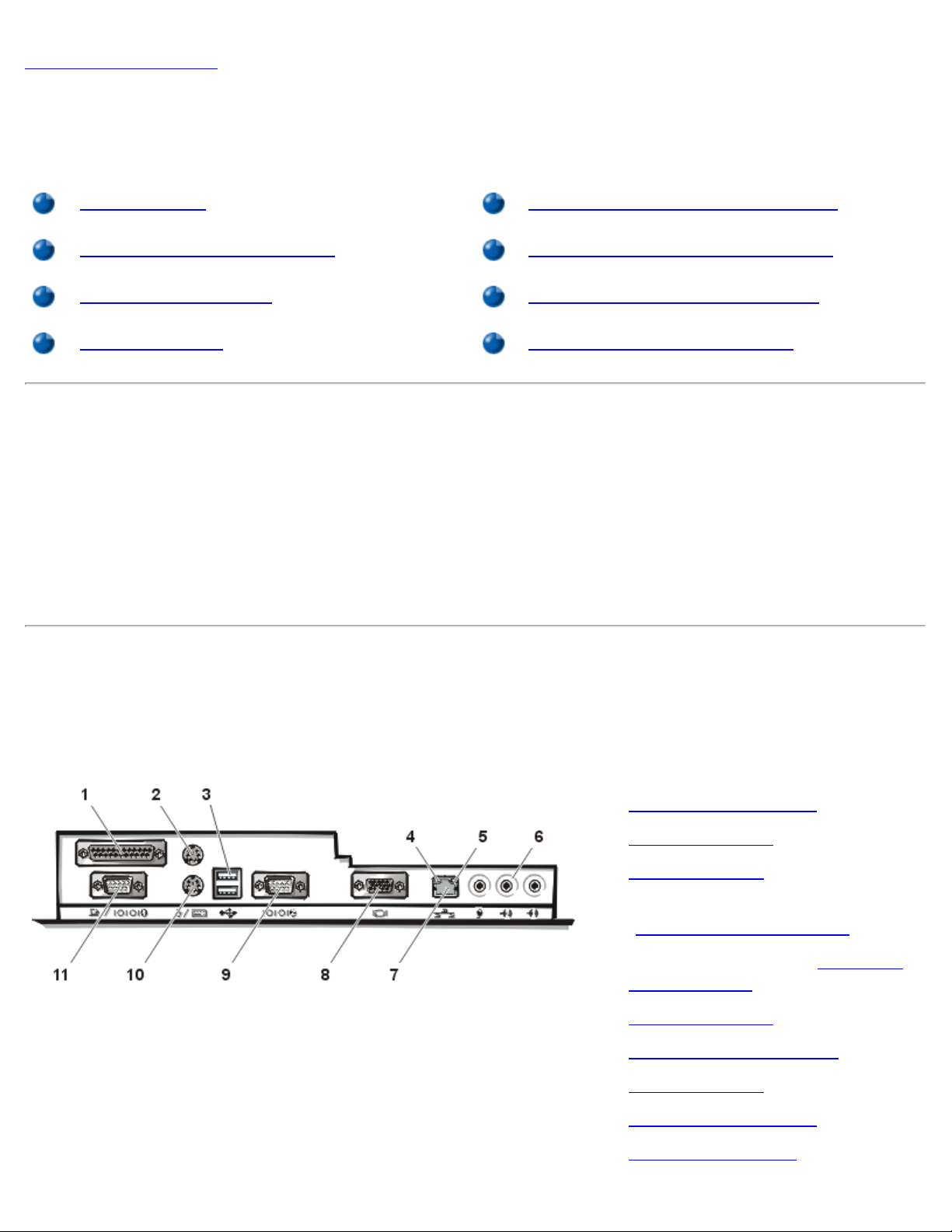
Figure 1 shows the connectors on the back of your computer for attaching external devices.
Figure 1. I/O Ports, Connectors, and Indicators
1 Parallel port connector
2 Mouse connector
3 USB connectors
4 Link integrity indicator (see
"Integrated NIC Connector
")
file:///C|/infodev/2013/eDoc/OpGX1/UG/setup.htm[2/21/2013 11:47:10 AM]
5 Activity indicator (see "Integrated
NIC Connector")
6 Audio connectors
7 Integrated NIC connector
8 Video connector
9 Serial port 2 connector
10 Keyboard connector
Page 13

Setup and Operation: Dell OptiPlex GX1 Small-Form-Factor System User's Guide
11 Serial port 1 connector
When you connect external devices to your computer's back panel, follow these guidelines:
Check the documentation that accompanied the device for specific installation and configuration
instructions.
For example, you must connect most devices to a particular input/output (I/O) port or connector to
operate properly. Also, external devices like a mouse or printer usually require you to load device
drivers into system memory before they will work.
Always attach external devices while your computer is turned off. Then turn on the computer before
turning on any external devices, unless the documentation for the device specifies otherwise. (If the
computer does not seem to recognize the device, try turning on the device before turning on the
computer.)
NOTICE: When you disconnect external devices from the back of the computer, wait 5
seconds after turning off the computer before you disconnect any devices to avoid
possible damage to the system board.
Parallel Port Connector
The integrated parallel port uses a 25-pin D-subminiature connector on the computer's back panel.
This I/O port sends data in parallel format (where eight data bits, or one byte, are sent simultaneously over
eight separate lines in a single cable). The parallel port is used primarily for printers.
The default designation of your computer's integrated parallel port is LPT1. Port designations are used, for
example, in software installation procedures to identify the port to which your printer is attached, thus telling
your software where to send its output. (An incorrect designation prevents the printer from printing or causes
scrambled print.)
NOTE: The integrated parallel port is automatically disabled if the system detects an installed
expansion card containing a parallel port configured to the same address as specified in the Parallel
Port option in the System Setup program.
Mouse Connector
Your system uses a Personal System/2 (PS/2)-compatible mouse. The mouse cable attaches to a 6-pin
miniature Deutsche Inductive Norm (DIN) connector on the back panel of your computer. Turn off the
computer and any attached peripherals before connecting a mouse to the computer.
A PS/2-compatible mouse works as does an industry-standard serial mouse or bus mouse except that it has
its own dedicated connector, which frees up the serial ports and does not require an expansion card. Mouse
driver software gives the mouse priority with the microprocessor by issuing interrupt request (IRQ) 12
whenever a new mouse movement is made. The drivers also pass along the mouse data to the application
that is in control.
USB Connectors
file:///C|/infodev/2013/eDoc/OpGX1/UG/setup.htm[2/21/2013 11:47:10 AM]
Page 14

Setup and Operation: Dell OptiPlex GX1 Small-Form-Factor System User's Guide
Your system contains two Universal Serial Bus (USB) connectors for attaching USB-compliant devices. USB-
compliant devices are typically peripherals such as keyboards, mice, printers, and computer speakers.
If you reconfigure your hardware, you may need pin number and signal information for the USB connectors.
Click one of the pins in the illustration for information on a particular signal.
Integrated NIC Connector
Your system has an integrated 10/100-megabit-per-second (Mbps) 3Com® Peripheral Component
Interconnect (PCI) 3C905B-TX Ethernet network interface controller (NIC). The NIC provides all the
functions of a separate network expansion card and supports both the 10BASE-T and 100BASE-TX
Ethernet standards.
The NIC includes a Wakeup On LAN feature that enables the computer to be started by a special local area
network (LAN) signal from a server management console. Wakeup On LAN provides remote computer setup,
software downloading and installation, file updates, and asset tracking after hours and on weekends when
LAN traffic is typically at a minimum.
The NIC connector on the computer's back panel has the following indicators:
A yellow activity indicator flashes when the system is transmitting or receiving network data. (A high
volume of network traffic may make this indicator appear to be in a steady "on" state.)
A dual-colored link integrity indicator, which lights up green when there is a good connection between a
10-Mbps network and the NIC, or it lights up orange when there is a good connection between a 100Mbps network and the NIC. When the green indicator is off, the computer is not detecting a physical
connection to the network.
Audio Connectors
You can use the microphone jack to attach a standard personal computer microphone. Connect the audio
cable from the microphone to the microphone jack. The microphone input is a monaural source with
maximum signal levels of 89 millivolts root-mean-squared (mVrms).
You can use the line-out jack to attach most computer speakers. The line-out jack is amplified, so speakers
with integrated amplifiers are not required. Connect the audio cable from the speakers to this jack.
You can use the line-in jack to attach record/playback devices such as cassette players, CD players, and
VCRs. Connect the line-out cable from any of these devices to the line-in jack on the back of your computer.
Video Connector
The system uses a 15-pin high-density D-subminiature connector on the back panel for attaching a video
graphics array (VGA)-compatible monitor to your system.
Serial Port Connectors
The serial ports use 9-pin D-subminiature connectors on the back panel. These ports support devices such
as external modems or plotters that require serial transmission (sending one bit of data at a time over one
line).
file:///C|/infodev/2013/eDoc/OpGX1/UG/setup.htm[2/21/2013 11:47:10 AM]
Page 15
Setup and Operation: Dell OptiPlex GX1 Small-Form-Factor System User's Guide
The default designations for these integrated serial ports are COM1 for serial port 1 and COM2 for serial port
2. Port designations are used in software installation procedures to identify the port used by a device—for
example, specifying the port used by a modem when installing communications software.
The system contains a reconfiguration feature to reassign the serial port's designation if you add an
expansion card containing a serial port using this designation.
If you set the system’s integrated serial ports to Auto in the System Setup program and add an expansion
card containing a serial port configured to a specific designation, the computer automatically maps (assigns)
the integrated ports to the appropriate COM setting as necessary.
Before you add a card with a serial port, check the documentation that accompanied your software to make
sure that the software can be mapped to the new COM port designation.
Keyboard Connector
Your system uses a PS/2-style keyboard. The keyboard cable attaches to a 6-pin miniature DIN connector
on the back panel of your computer.
Network Cable Requirements
Your computer's NIC connector (an RJ45 connector located on the back panel) is designed for attaching an
unshielded twisted pair (UTP) Ethernet cable. Press one end of the UTP cable into the NIC connector until
the cable snaps securely into place.
Connect the other end of the cable to an RJ45 jack wall plate or to an RJ45 port on a UTP concentrator or
hub, depending on your network configuration.
Controls and Indicators
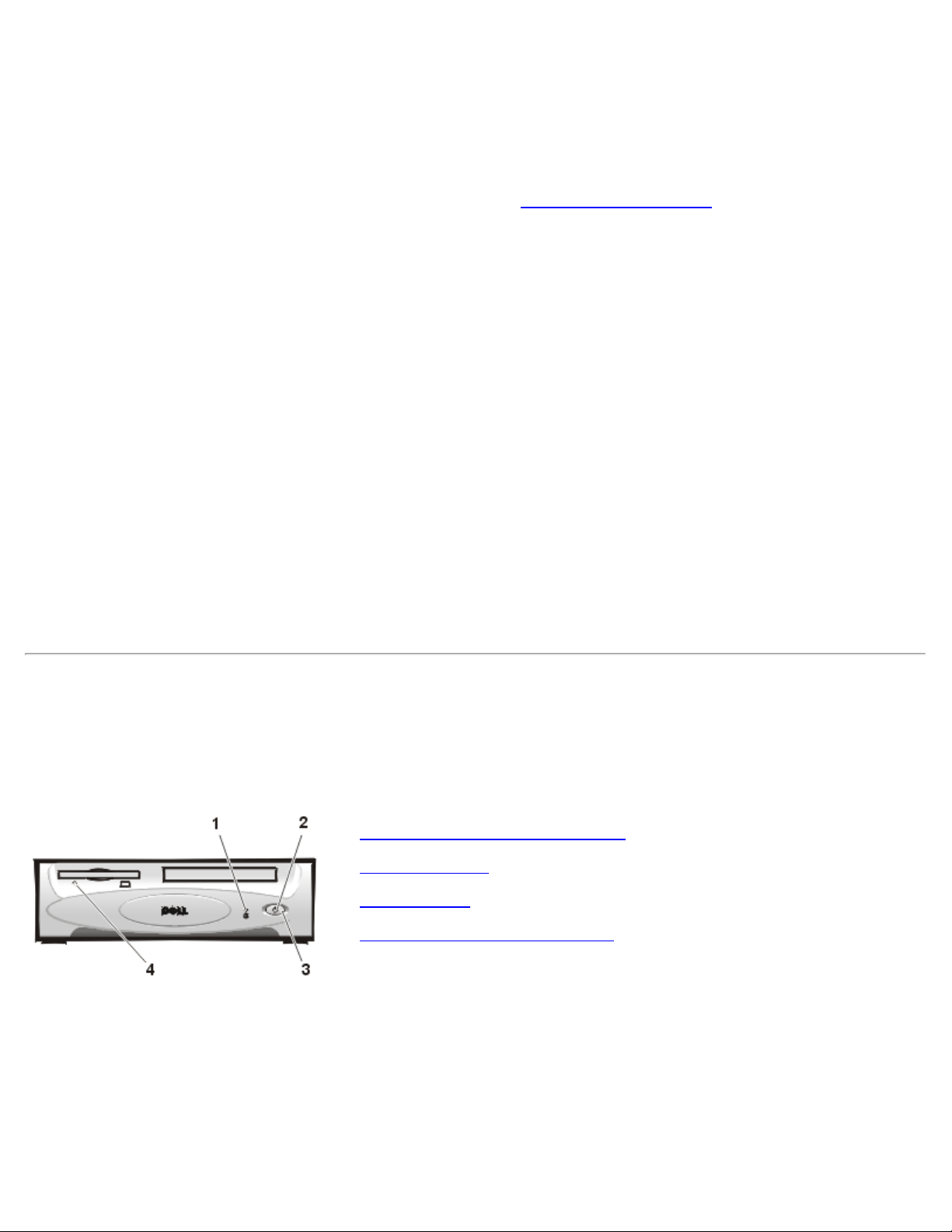
Figure 2 shows the controls and indicators on the front panel of your computer.
Figure 2. Controls and Indicators
1 Hard-disk drive access indicator
2 Power indicator
3 Power button
4 Diskette-drive access indicator
Hard-Disk Drive Access Indicator
The hard-disk drive access indicator lights up when a hard-disk drive is reading data from or writing data to
the drive.
Power Indicator
file:///C|/infodev/2013/eDoc/OpGX1/UG/setup.htm[2/21/2013 11:47:10 AM]
Page 16
Setup and Operation: Dell OptiPlex GX1 Small-Form-Factor System User's Guide
The power indicator in the center of the power button lights up when the computer is receiving power. Use
operating systems and for Windows 98 operating systems that have the ACPI feature disabled.
the power indicator to help you identify a system problem if the system does not boot when you press the
power button to turn on the computer.
CAUTION: Before you remove DIMMs, see "Safety First—For You and Your Computer."
A solid green power indicator and a beep code during power-on self-test (POST) indicate that a dual inline memory module (DIMM) may be faulty or is not properly seated. Remove all DIMMs
, install only
one DIMM, and then reboot. Repeat this procedure until you identify the faulty or improperly seated
DIMM.
A solid green power indicator and no beep code and no video during POST indicate that the monitor or
the integrated video controller may be faulty. See "Troubleshooting the Monitor
operating properly and is correctly connected, see "Getting Help
" for instructions on getting technical
." If the monitor is
assistance from Dell.
A solid green power indicator and no beep code with video during POST indicate that an integrated
system board device may be faulty. See "Getting Help
" for instructions on getting technical assistance
from Dell.
Power Button
The power button controls the system's AC input power.
The Microsoft® Windows® 98 and Windows 98 Second Edition (SE) operating systems let you configure the
function of the power button through the Advanced Configuration and Power Interface (ACPI) feature (see
Table 1).
NOTICE: To turn off your computer system, perform an orderly system shutdown using the operating
system menu when possible.
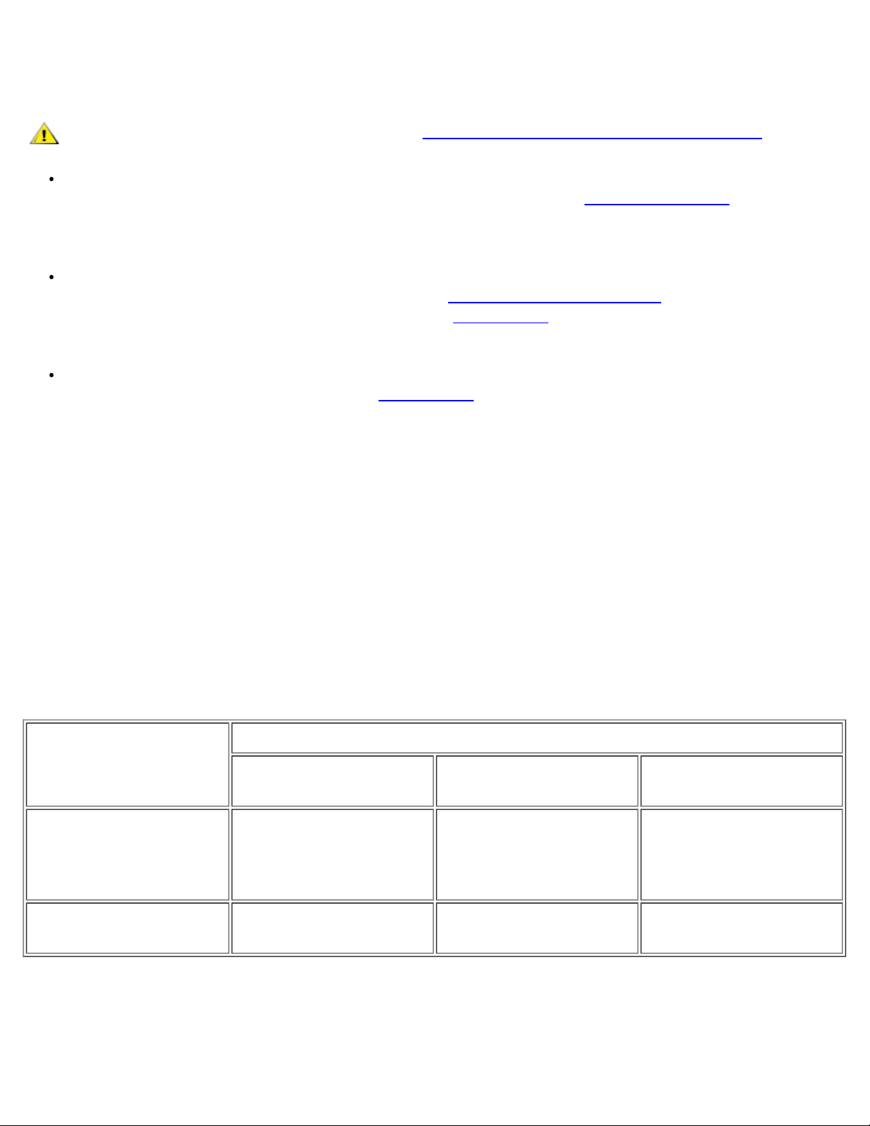
Table 1. Power Button Behavior Under Microsoft Windows 98 and Windows 98 SE Operating Systems
With ACPI
Action Results
System Turned On
and ACPI Enabled
Press power button System goes into
standby mode or turns
System in Standby
System Turned Off
Mode
System turns on Boots and system turns
on
off (depending on the
operating system setup)
Hold power button
for 6 seconds*
System turns off
immediately
System turns off
immediately
Boots and system turns
on
* Pressing or holding the power button to shut down the system may result in data loss. Use the power
button to shut down the system only if the operating system is not responding.
Microsoft Windows 95 does not support ACPI. Table 2 shows power button functions for Windows 95
file:///C|/infodev/2013/eDoc/OpGX1/UG/setup.htm[2/21/2013 11:47:10 AM]
Page 17
Setup and Operation: Dell OptiPlex GX1 Small-Form-Factor System User's Guide
Table 2. Power Button Behavior Under Microsoft Windows 95 and Windows 98 (With Dell
AutoShutdown Loaded)
Action Results
System Turned On System in Suspend
System Turned Off
Mode
Press power button System turns off System turns off Boots and system turns
on
Hold power button for 6
seconds*
System turns off
immediately
System turns off
immediately
Boots and system turns
on
* Pressing or holding the power button to shut down the system may result in data loss. Use the power
button to shut down the system only if the operating system is not responding.
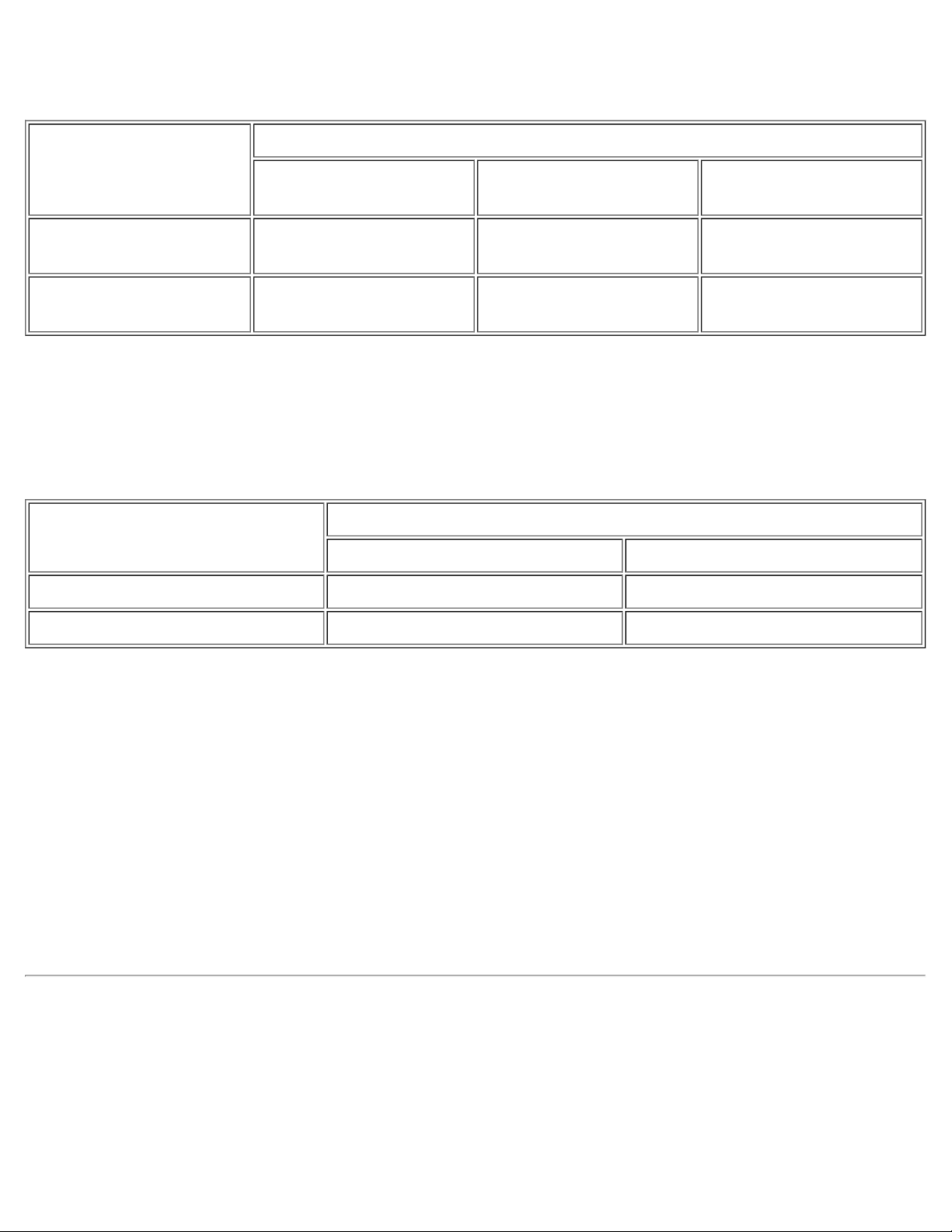
Table 3 shows power button functions for Microsoft Windows NT® operating systems.
Table 3. Power Button Behavior Under Microsoft Windows NT (With Dell AutoShutdown Loaded)
Action Results
System Turned On System Turned Off
Press power button System shuts down Boots and system turns on
Hold power button for 6 seconds* System turns off immediately Boots and system turns on
* Pressing or holding the power button to shut down the system may result in data loss. Use the power
button to shut down the system only if the operating system is not responding.
If the system does not turn off when you press the power button, the system may be hung. Press and hold
the power button until the system turns off completely (this process may take several seconds). Alternatively,
press the reset button to reset the system and reboot. If the system is hung and both buttons fail to function
properly, unplug the AC power cable from the computer, wait for it to completely stop running, plug in the AC
power cable, and if it the system does not restart, press the power button to restart the system.
Diskette-Drive Access Indicator
The diskette-drive access indicator lights up when the drive is reading data from or writing data to a diskette.
Wait until the access indicator turns off before removing a diskette from the drive.
Chassis Intrusion
An integrated chassis intrusion alarm displays the status of the system chassis intrusion monitor. If the
chassis has been opened, the setting changes to Detected and the following message is displayed during
the boot sequence at system start-up:
Alert! Cover was previously removed.
file:///C|/infodev/2013/eDoc/OpGX1/UG/setup.htm[2/21/2013 11:47:10 AM]
Page 18
Setup and Operation: Dell OptiPlex GX1 Small-Form-Factor System User's Guide
Use the the Chassis Intrusion options in the System Setup program to reset the alarm so that future
intrusions are detected.
Security Cable Slot and Padlock Ring
On the back of the computer are a security cable slot and padlock ring (see Figure 3) for attaching
commercially available antitheft devices. (The padlock ring is recessed inside the cover.) Security cables for
personal computers usually include a segment of galvanized cable with an attached locking device and key.
To prevent unauthorized removal of your computer, loop the cable around an immovable object, insert the
locking device into the security cable slot on the back of your computer, and lock the device with the key
provided. Complete instructions for installing this kind of antitheft device are usually included with the device.
NOTE: Antitheft devices are of differing designs. Before purchasing such a device, make sure it works
with the cable slot on your computer.
The padlock ring allows you to secure the computer cover to the chassis to prevent unauthorized access to
the inside of the computer. To use the padlock ring, insert a commercially available padlock through the ring
and then lock the padlock.
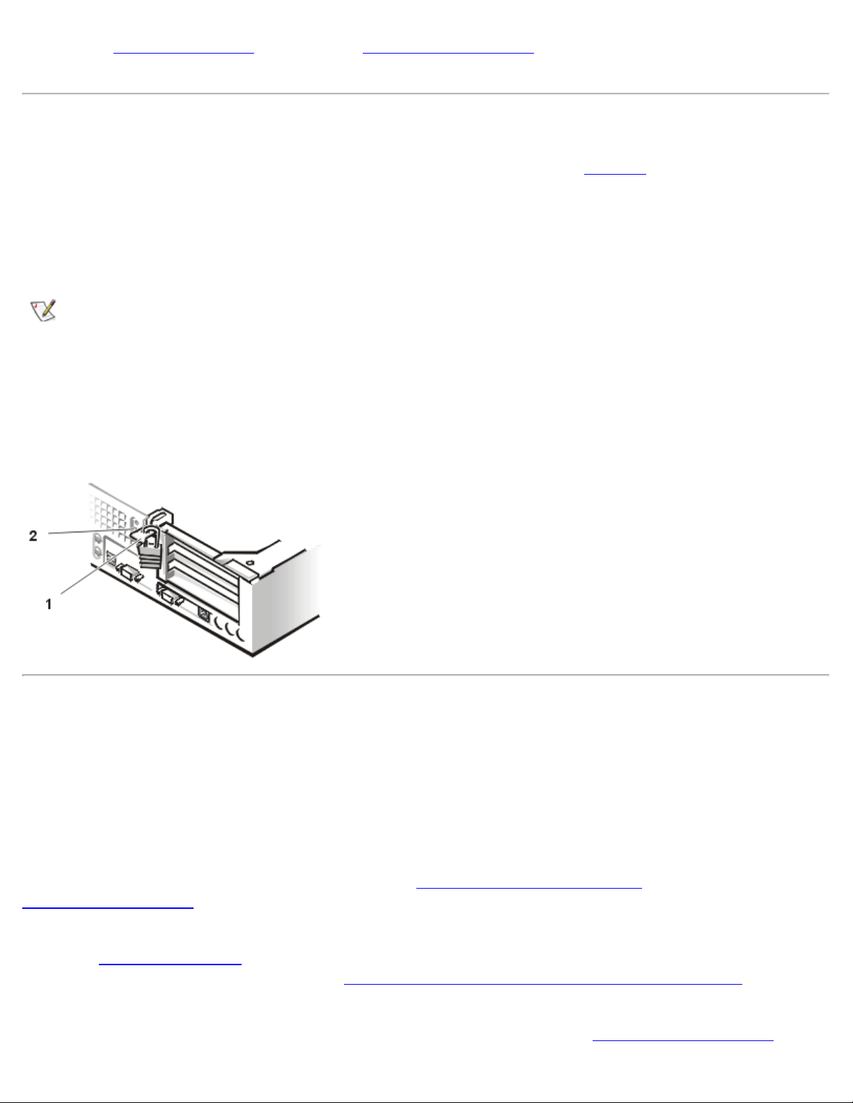
Figure 3. Security Cable Slot and Padlock Ring
1 Padlock ring
2 Security cable slot
Using the System Password Feature
NOTICE: The password features provide a basic level of security for the data on your system.
However, they are not foolproof. If your data requires more security, it is your responsibility to obtain
and use additional forms of protection, such as data encryption programs.
Your Dell system is shipped to you without the system password feature enabled. If system security is a
concern, operate your system only with system password protection.
You can assign a system password, as described in "Assigning a System Password
System Setup program
. After a system password is assigned, only those who know the password have full
," whenever you use the
use of the system.
When the System Password option is set to Enabled, the computer system prompts you for the system
password just after the system boots. See "Using Your System Password to Secure Your System
" for more
information.
To change an existing system password, you must know the password (see "Deleting or Changing an
file:///C|/infodev/2013/eDoc/OpGX1/UG/setup.htm[2/21/2013 11:47:10 AM]
Page 19

Setup and Operation: Dell OptiPlex GX1 Small-Form-Factor System User's Guide
Existing System Password"). If you assign and later forget a system password, you must remove the
computer cover to change a jumper setting that disables the system password feature (see "Disabling a
Forgotten Password"). Note that you erase the setup password at the same time.
NOTICE: If you leave your system running and unattended without having a system password
assigned, or if you leave your computer unlocked so that someone can disable the password by
changing a jumper setting, anyone can access the data stored on your hard-disk drive.
Assigning a System Password
Before you can assign a system password, you must enter the System Setup program
System Password
When a system password is assigned, the setting shown in System Password
option.
is Enabled. When the
and check the
system password feature is disabled by a jumper setting on the system board, the setting shown is Disabled
by Jumper. You cannot change or enter a new system password if either of these options is displayed.
When no system password is assigned and the password jumper on the system board is in the Enabled
position (its default), the option shown for the System Password
option is Not Enabled. Only when System
Password is set to Not Enabled can you assign a system password, using the following procedure:
1. Verify that Password Status
2. Highlight System Password
is set to Unlocked.
, and then press the left- or right-arrow key.
The option heading changes to Enter Password, followed by an empty 32-character field in square
brackets.
3. Type your new system password.
You can use up to 32 characters in your password.
As you press each character key (or the spacebar for a blank space), a placeholder appears in
the field. The password assignment operation recognizes keys by their location on the keyboard,
without distinguishing between lowercase and uppercase characters. For example, if you have an
M in your password, the system recognizes either M or m as correct.
Certain key combinations are not valid. If you enter one of these combinations, the speaker emits
a beep.
To erase a character when entering your password, press the <Backspace> key or the left-arrow
key.
NOTE: To escape from the field without assigning a system password, press the <Tab>
key or the <Shift><Tab> key combination to move to another field, or press the <Esc> key
at any time prior to completing step 5.
4. Press <Enter>.
If the new system password is less than 32 characters, the whole field fills with placeholders.
Then the option heading changes to Verify Password, followed by another empty 32-character
field in square brackets.
file:///C|/infodev/2013/eDoc/OpGX1/UG/setup.htm[2/21/2013 11:47:10 AM]
Page 20

Setup and Operation: Dell OptiPlex GX1 Small-Form-Factor System User's Guide
5. To confirm your password, type it a second time and press <Enter>.
The password setting changes to Enabled. Your system password is now set; you can exit the
System Setup program and begin using your system. Note, however, that password protection
does not take effect until you reboot the system by pressing the reset button or by turning the
system off and then on again.
Using Your System Password to Secure Your System
Whenever you either turn on your system or press the reset button, or when you reboot the system by
pressing the <Ctrl><Alt><Del> key combination, the following prompt appears on the screen when
Password Status
is set to Unlocked:
Type in the password and
- press <ENTER> to leave password security enabled.
- press <CTRL><ENTER> to disable password security.
Enter password:
If Password Status
is set to Locked, the following prompt appears:
Type the password and press <Enter>.
After you type the correct system password and press <Enter>, your system boots and you can use the
keyboard and/or mouse to operate your system as usual.
NOTE: If you have assigned a setup password (see "Using the Setup Password Feature"), the system
accepts your setup password as an alternate system password.
If you enter a wrong or incomplete system password, the following message appears on the screen:
** Incorrect password. **
Enter password:
If you again enter an incorrect or incomplete system password, the same message appears on the screen.
The third and subsequent times you enter an incorrect or incomplete system password, the system displays
the following message:
** Incorrect password. **
Number of unsuccessful password attempts: 3
System halted! Must power down.
The number of unsuccessful attempts made to enter the correct system password can alert you to an
unauthorized person attempting to use your system.
Even after your system is turned off and on, the previous message is displayed each time an incorrect or
incomplete system password is entered.
NOTE: You can use Password Status in conjunction with System Password and Setup Password
to further protect your system from unauthorized changes.
Deleting or Changing an Existing System Password
file:///C|/infodev/2013/eDoc/OpGX1/UG/setup.htm[2/21/2013 11:47:10 AM]
Page 21

Setup and Operation: Dell OptiPlex GX1 Small-Form-Factor System User's Guide
To delete or change an existing system password, perform the following steps:
1. Enter the System Setup program
, and verify that Password Status is set to Unlocked.
2. Reboot your system to force it to prompt you for a system password.
3. When prompted, type the system password.
4. Press <Ctrl><Enter> to disable the existing system password, instead of pressing <Enter> to continue
with the normal operation of your system.
5. Confirm that Not Enabled is displayed for the System Password option of the System Setup program.
If Not Enabled appears in the System Password option, the system password has been deleted.
If you want to assign a new password, continue to step 6. If Not Enabled is not displayed for the
System Password option, press <Alt><B> to reboot the system, and then repeat steps 3 through
5.
6. To assign a new password, follow the procedure in "Assigning a System Password
."
Using the Setup Password Feature
Your Dell system is shipped to you without the setup password feature enabled. If system security is a
concern, you should operate your system with setup password protection.
You can assign a setup password, as described in "Assigning a Setup Password," whenever you use the
System Setup program. After you assign a setup password, only those who know the password have full use
of the System Setup program. See "Operating Your System With A Setup Password Enabled
" for more
information.
To change an existing setup password, you must know the setup password (see "Deleting or Changing an
Existing Setup Password"). If you assign and later forget a setup password, you need to remove the
computer cover to change a jumper setting that disables the setup password feature (see "Disabling a
Forgotten Password"). Note that you erase the system password at the same time.
Assigning a Setup Password
You can assign a setup password only if Setup Password is set to Not Enabled. To assign a setup
password, highlight Setup Password and press the left- or right-arrow key. The system prompts you to
enter and verify the password. If a character is illegal for password use, the system emits a beep.
NOTES: The setup password can be the same as the system password.
If the two passwords are different, the setup password can be used as an alternate system password.
However, the system password cannot be used in place of the setup password.
After you verify the password, the Setup Password setting changes to Enabled. The next time you enter
the System Setup program, the system prompts you for the setup password.
A change to Setup Password becomes effective immediately (rebooting the system is not required).
file:///C|/infodev/2013/eDoc/OpGX1/UG/setup.htm[2/21/2013 11:47:10 AM]
Page 22

Setup and Operation: Dell OptiPlex GX1 Small-Form-Factor System User's Guide
Operating Your System With a Setup Password Enabled
If Setup Password is set to Enabled, you must enter the correct setup password before you can modify the
majority of the System Setup options.
When you start the System Setup program, the System Setup screen appears with Setup Password
highlighted, prompting you to type the password.
If you do not enter the correct password in three tries, the system lets you view, but not modify, the System
Setup screen—with the following exceptions:
You can still modify the Date, Time, CPU Speed, Num Lock, and Speaker options.
If System Password is not enabled and is not locked via the Password Status option, you can assign
a system password (however, you cannot disable or change an existing system password).
NOTE: You can use Password Status in conjunction with Setup Password to protect the system
password from unauthorized changes.
Deleting or Changing an Existing Setup Password
To delete or change an existing setup password, perform the following steps:
1. Enter the System Setup program.
2. Highlight Setup Password and press the left- or right-arrow key to delete the existing setup password.
The setting changes to Not Enabled.
3. If you want to assign a new setup password, perform the steps in "Assigning a Setup Password
."
Disabling a Forgotten Password
If you forget your system or setup password, you cannot operate your system or change settings in the
System Setup program
the passwords, and erase the existing passwords.
To disable a forgotten password, perform the following steps.
until you remove the computer cover, change the password jumper setting to disable
CAUTION: Before you remove the computer cover, see "Safety First—For You and Your
Computer."
1. Remove the computer cover according to the instructions in "Removing and Replacing the Computer
Cover."
2. Remove the jumper plug from the PSWD jumper to disable the password feature.
Refer to "System Board Jumpers
" for jumper information and to Figure 4 in "Inside Your
Computer" for the location of the password jumper (labeled "PSWD") on the system board.
file:///C|/infodev/2013/eDoc/OpGX1/UG/setup.htm[2/21/2013 11:47:10 AM]
Page 23

Setup and Operation: Dell OptiPlex GX1 Small-Form-Factor System User's Guide
3. Replace the computer cover.
4. Reconnect your computer and peripherals to an electrical outlet, and then turn them on.
Booting your system with the PSWD jumper plug removed erases the existing password(s).
5. Enter the System Setup program, and verify that the password is disabled. Proceed to step 6 if you
want to assign a new password.
NOTE: Before you assign a new system and/or setup password, you must replace the
PSWD jumper plug.
CAUTION: Before you remove the computer cover, see "Safety First—For You and Your
Computer."
6. Remove the computer cover according to the instructions in "Removing and Replacing the Computer
Cover."
7. Replace the PSWD jumper plug.
8. Replace the computer cover, and then reconnect the computer and peripherals to an electrical outlet
and turn them on.
Booting your system with the PSWD jumper installed reenables the password feature. When you
enter the System Setup program, both password options appear as Not Enabled, meaning that
the password feature is enabled but that no password has been assigned.
9. Assign a new system and/or setup password.
To assign a new system password, see "Assigning a System Password
password, see "Assigning a Setup Password
."
." To assign a new setup
Back to Contents Page
file:///C|/infodev/2013/eDoc/OpGX1/UG/setup.htm[2/21/2013 11:47:10 AM]
Page 24

Using the System Setup Program: Dell OptiPlex GX1 Small-Form-Factor System User's Guide
Back to Contents Page
Using the System Setup Program: Dell™ OptiPlex™ GX1 SmallForm-Factor System User's Guide
Overview System Setup Navigation Keys
Entering the System Setup Program System Setup Options
System Setup Screens
Overview
Each time you turn on your computer system or press the reset button, the system compares the hardware
installed in the system to the hardware listed in the system configuration information stored in nonvolatile
random-access memory (NVRAM) on the system board. If the system detects a discrepancy, it generates
error messages that identify the incorrect configuration settings. The system then prompts you to enter the
System Setup program to correct the setting.
You can use the System Setup program as follows:
To change the system configuration information after you add, change, or remove any hardware in your
system
To set or change user-selectable options—for example, the time or date on your system
You can view the current settings at any time. When you change a setting, in many cases you must reboot
the system before the change takes effect.
After you set up your system, run the System Setup program to familiarize yourself with your system
configuration information and optional settings. Dell recommends that you print the System Setup screens
(by pressing the <Print Screen> key) or write down the information for future reference.
Before you use the System Setup program, you need to know the kind of diskette drive(s) and hard-disk
drive(s) installed in your computer. If you are unsure of any of this information, see the Manufacturing Test
Report that was shipped with your system and is located in the Dell Accessories folder.
Entering the System Setup Program
To enter the System Setup program, perform the following steps:
1. Turn on your system.
If your system is already on, shut it down and then turn it on again.
2. Press <F2> immediately when the F2 = Setup prompt appears in the upper-right corner of the Dell
file:///C|/infodev/2013/eDoc/OpGX1/UG/sysetup.htm[2/21/2013 11:47:11 AM]
Page 25
Using the System Setup Program: Dell OptiPlex GX1 Small-Form-Factor System User's Guide
logo screen.
If you wait too long and your operating system begins to load into memory, let the system complete the load
operation; then shut down the system and try again.
NOTE: To ensure an orderly system shutdown, consult the documentation that accompanied your
operating system.
You can also enter the System Setup program by responding to certain error messages. See "Responding to
Error Messages."
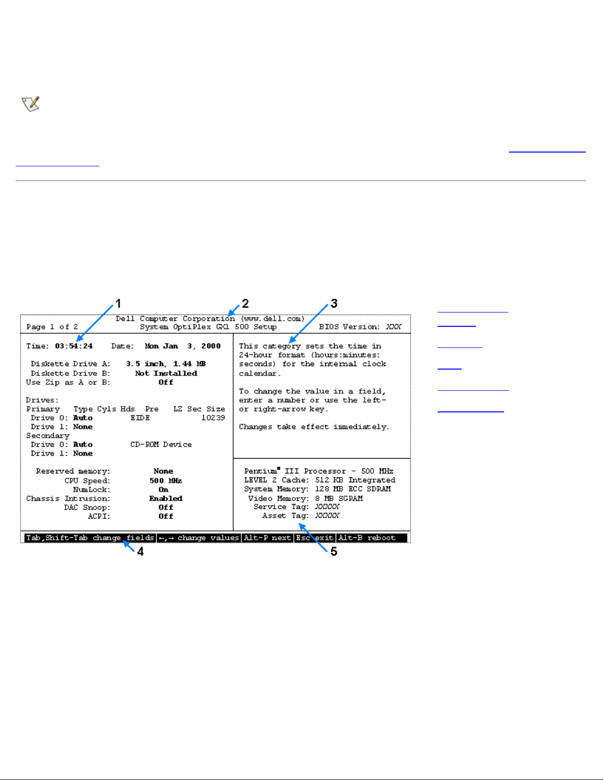
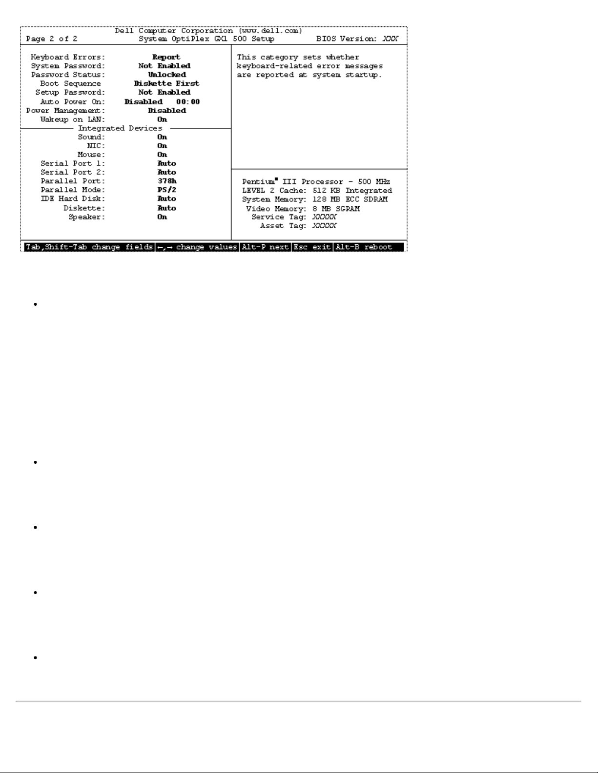
System Setup Screens
The two System Setup screens, Page 1 and Page 2, display the current setup and configuration information
and optional settings for your system. (Typical examples are illustrated in Figure 1.)
Figure 1. Typical Examples of System Setup Screens (Page 1 and Page 2)
1 Configuration
options
2
Title box
3
Help
4
Key functions
5
System data
file:///C|/infodev/2013/eDoc/OpGX1/UG/sysetup.htm[2/21/2013 11:47:11 AM]
Page 26
Using the System Setup Program: Dell OptiPlex GX1 Small-Form-Factor System User's Guide
Information on the two System Setup screens is organized in five boxed areas:
Configuration options
The box on the left half of both screens lists the options that define the installed hardware in your
computer.
Fields beside the options contain settings; those that appear bright on the screen can be
changed. Settings that you cannot change because they are determined by the system appear
less bright.
Some options have multiple fields, which may show settings as bright or less bright depending on
what options or values you entered in other fields.
Title box
The box at the top of both screens lists the system name, page number (Page 1 or Page 2), and
the revision number of the basic input/output system (BIOS).
Help
The box on the upper-right half of both screens displays help information for the option with a
currently highlighted field.
Key functions
The line of boxes across the bottom of both screens lists keys and their functions within the
System Setup program.
System data
The box in the lower-right corner of both screens displays information about your system.
System Setup Navigation Keys
file:///C|/infodev/2013/eDoc/OpGX1/UG/sysetup.htm[2/21/2013 11:47:11 AM]
Page 27
Using the System Setup Program: Dell OptiPlex GX1 Small-Form-Factor System User's Guide
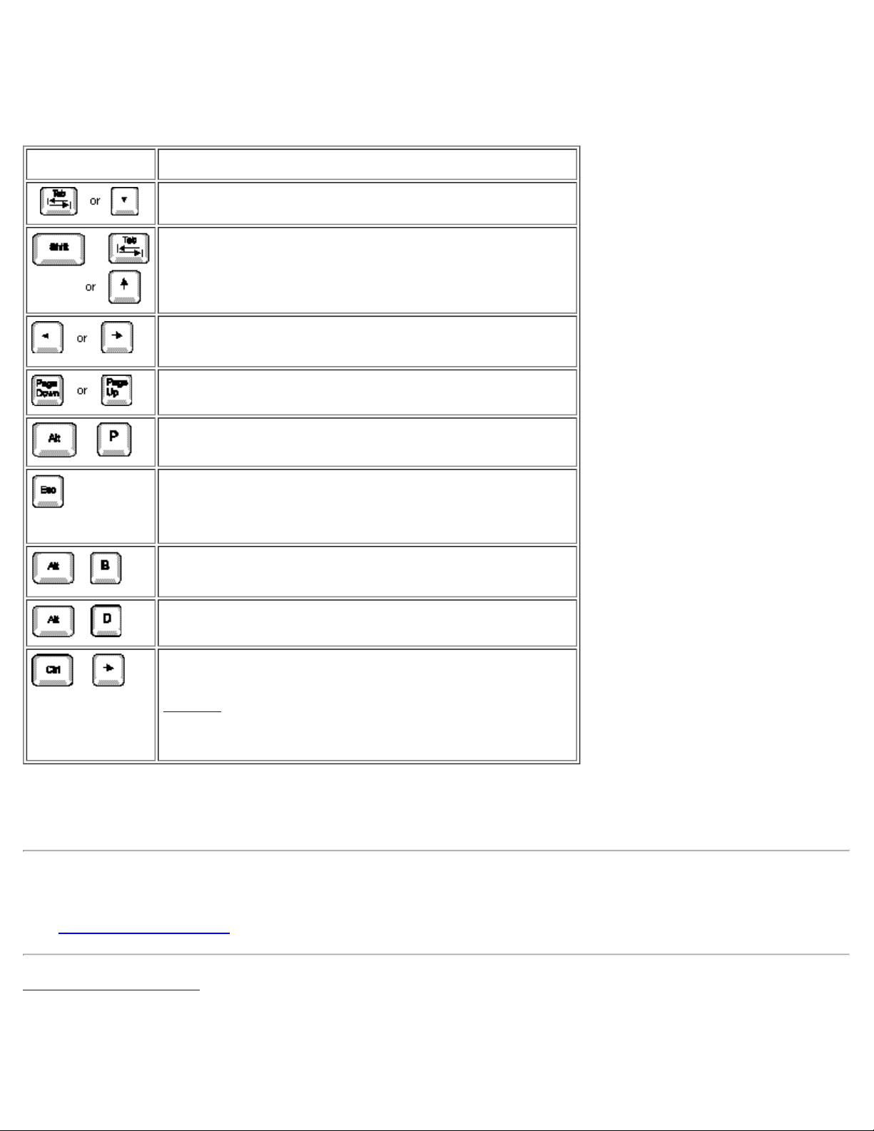
Table 1 lists the keys you use to view or change information on the System Setup screens and to exit the
program.
Table 1. System-Setup Navigation Keys
Keys Action
Moves to the next field.
Moves to the previous field.
Cycles through the options in a field. In many fields,
you can also type the appropriate value.
Scrolls through help information.
Switches between Page 1 and Page 2.
Exits the System Setup program without rebooting
the system and returns the system to its previous
state—the boot routine.
*
Exits the System Setup program and reboots the
system, implementing any changes you have made.
Resets the selected option to its default.
Enters the Device List screen when the Boot
Devices menu option is set to Device List. See
Table 2 in "System Setup Options" for more
information on the keys you use in the Device List
screen.
*
For most of the options, any changes you make are recorded but do not take effect until the next time you
boot the system. For a few options (as noted in the help area), the changes take effect immediately.
System Setup Options
See System Setup Options for information.
Back to Contents Page
file:///C|/infodev/2013/eDoc/OpGX1/UG/sysetup.htm[2/21/2013 11:47:11 AM]
Page 28
Installing Upgrades: Dell OptiPlex GX1 Small-Form-Factor System User's Guide
Back to Contents Page
Installing Upgrades: Dell™ OptiPlex™ GX1 Small-Form-Factor
System User's Guide
Inside Your Computer Microprocessor
Expansion Cards Battery
System Memory CD-ROM Drives
Video Memory Hard-Disk Drives
Back to Contents Page
file:///C|/infodev/2013/eDoc/OpGX1/UG/install.htm[2/21/2013 11:47:12 AM]
Page 29

Troubleshooting: Dell OptiPlex GX1 Small-Form-Factor System User's Guide
Back to Contents Page
Troubleshooting: Dell™ OptiPlex™ GX1 Small-Form-Factor
System User's Guide
Basic Checks External Components
Messages and Codes Internal Components
Software Checks Getting Help
Dell Diagnostics
Back to Contents Page
file:///C|/infodev/2013/eDoc/OpGX1/UG/trouble.htm[2/21/2013 11:47:12 AM]
Page 30
Specifications: Dell OptiPlex GX1 Small-Form-Factor System User's Guide
Back to Contents Page
Specifications: Dell™ OptiPlex™ GX1 Small-Form-Factor System
User's Guide
Processor Ports
Memory Key Combinations
System Information Controls and Indicators
Video Power
Audio Physical
Expansion Bus Environmental
Drives
Processor
Microprocessor type Intel® Pentium® II or Pentium III microprocessor
Internal cache 32 kilobyte (KB) (16-KB data cache, 16-KB instruction cache)
L2 cache memory 512-KB pipeline burst, 4-way set-associative, write-back static random-
access memory (SRAM)
Math coprocessor Internal to the microprocessor
Memory
Architecture 64-bit (non-error checking and correction [ECC]) or 72-bit (ECC),
noninterleaved, "PC100" 100 megahertz (MHz)
Dual inline memory module
(DIMM) sockets
DIMM capacities 32-, 64-, 128-, and 256-megabyte (MB) synchronous dynamic random-
System RAM 32–768 MB
file:///C|/infodev/2013/eDoc/OpGX1/UG/specs.htm[2/21/2013 11:47:12 AM]
Three (gold contacts)
access memory (SDRAM)
Page 31

Specifications: Dell OptiPlex GX1 Small-Form-Factor System User's Guide
Basic input/output system
F0000h
(BIOS) address
System Information
System chip set Intel 440BX PIIX4e
Data bus width 64 bits
Address bus width 32 bits
Direct memory access
(DMA) channels
Interrupts 15
System BIOS 2-megabit (Mb) flash chip
System clock 66 or 100 MHz (matches external bus speed)
Eight
Video
Video type Integrated ATI Rage Pro (AGP 2X) graphics
Video memory 4 MB standard (upgradable to 8 MB) synchronous graphics RAM (SGRAM)
Video resolutions 640 x 480; true-color (32 bits per pixel [bpp]); 85 hertz (Hz); 4 MB SGRAM
800 x 600; true-color (32 bpp); 85 Hz; 4 MB SGRAM
1024 x 768; true-color (32 bpp); 85 Hz;
4 MB SGRAM
1280 x 1024; true-color (32 bpp); 85 Hz;
8 MB SGRAM
1600 x 1200; 65,535 colors (16 bpp); 75 Hz;
8 MB SGRAM
Audio
Model Crystal Semiconductor
Chip set CS4236
Expansion Bus
Bus types Peripheral Component Interconnect (PCI)
Bus speed 33 MHz
Expansion-card
connectors:
file:///C|/infodev/2013/eDoc/OpGX1/UG/specs.htm[2/21/2013 11:47:12 AM]
Two PCI expansion slots (half-length PCI expansion cards only)
Page 32

Specifications: Dell OptiPlex GX1 Small-Form-Factor System User's Guide
120 pins
PCI expansioncard connector
size
32 bits
PCI expansioncard connector
data width
(maximum)
Drives
Externally accessible bays One 3.5-inch bay for a 3.5-inch diskette drive; one 5.25-inch bay for a
removable media device (slim-height devices only)
Internally accessible bays One bay for a 1-inch-high enhanced integrated drive electronics (EIDE) hard-
disk drive
Ports
Externally accessible:
Serial (data
terminal
equipment
[DTE])
Parallel
Video
Network
interface
controller (NIC)
Two 9-pin connectors; 16550-compatible
25-hole connector (bidirectional)
15-hole connector
RJ45 connector
6-pin mini-Deutsche Industrie Norm (DIN)
Personal
System/2
(PS/2)-style
keyboard
file:///C|/infodev/2013/eDoc/OpGX1/UG/specs.htm[2/21/2013 11:47:12 AM]
Page 33

Specifications: Dell OptiPlex GX1 Small-Form-Factor System User's Guide
6-pin mini-DIN
PS/2compatible
mouse
Two USB-compliant connectors
Universal Serial
Bus (USB)
Miniature audio jack
Audio line-in
Miniature audio jack
Audio line-out
(amplified
source)
Miniature audio jack
Microphone
Internally accessible:
Primary EIDE
hard-disk drive
Secondary
EIDE hard-disk
drive
Diskette drive
ATI multimedia
Advanced
Technology
Attachment
Packet Interface
(ATAPI)
40-pin connector on PCI local bus
40-pin connector on PCI local bus
34-pin connector
40-pin connector
4-pin connector
Key Combinations
<Ctrl><Alt><Del> Restarts (reboots) the system
file:///C|/infodev/2013/eDoc/OpGX1/UG/specs.htm[2/21/2013 11:47:12 AM]
Page 34

Specifications: Dell OptiPlex GX1 Small-Form-Factor System User's Guide
<Ctrl><Alt><\> Toggles microprocessor speeds on 101-key keyboard (in MS-DOS® real
mode only)
<Ctrl><Alt><#> Toggles microprocessor speeds on 102-key keyboard (in MS-DOS real mode
only)
<F2> or
<Ctrl><Alt><Enter>
<F3> or <F12> Automatically starts (boots) the system from the network environment
<F10> Launches the utility partition (if installed) during system start-up
Starts the System Setup program (during power-on system test [POST] only)
specified by the Managed Boot Agent (MBA) rather than from one of the
devices in the
System Setup Boot Sequence option
Controls and Indicators
Reset control No reset button on small-form-factor systems
Power control Push button
Power indicators Green light-emitting diode (LED) on riser board; blinking green in sleep state;
dual-color LED on front panel—green for power, yellow for diagnostics
Hard-disk drive access
indicator
Link integrity indicator (on
NIC connector)
Green LED
Green LED for 10-Mb operation; orange LED for 100-Mb operation
Activity indicator (on NIC
connector)
Yellow LED
Power
DC power supply:
Small-form-factor chassis: 110
Wattage
Small-form-factor chassis: 808 British thermal units (BTU)/hr (nominal)
Heat dissipation
90 to 135 volts (V) at 60 Hz; 180 to 265 V at 50 Hz
Voltage
Backup battery 3-V CR2032 coin cell
Physical
file:///C|/infodev/2013/eDoc/OpGX1/UG/specs.htm[2/21/2013 11:47:12 AM]
Page 35

Specifications: Dell OptiPlex GX1 Small-Form-Factor System User's Guide
Height 9.1 cm (3.6 inches)
Width 31.8 cm (12.5 inches)
Depth 37.8 cm (14.9 inches)
Weight 6.6 kilograms (kg) (14.5 pounds [lb])
Environmental
Temperature:
10° to 35°Celsius (C) (50° to 95°Fahrenheit [F])
Operating
–40° to 65°C (–40° to 149°F)
Storage
Relative humidity 20% to 80% (noncondensing)
Maximum vibration:
Operating
Storage
Maximum shock:
Operating
Storage
Altitude:
Operating
0.25 gravities (G) at 3 to 200 Hz at 1 octave/min
0.5 G at 3 to 200 Hz at 1 octave/min
Bottom half-sine pulse with a change in velocity of 20 inches/sec (50.8
cm/sec)
27-G faired square wave with a velocity change of 200 inches/sec (508
cm/sec)
–16 to 3048 meters (m)* (–50 to 10,000 feet [ft])
–16 to 10,600 m (–50 to 35,000 ft)
Storage
* The maximum operating temperature of 35°C (95°F) is for altitudes below 914.6 m (3000 ft). Above 914.6
m the maximum operating temperature is reduced.
Back to Contents Page
file:///C|/infodev/2013/eDoc/OpGX1/UG/specs.htm[2/21/2013 11:47:12 AM]
Page 36

System Memory: Dell OptiPlex GX1 Small-Form-Factor System User's Guide
Back to Contents Page
System Memory: Dell™ OptiPlex™ GX1 Small-Form-Factor System
User's Guide
Overview Removing DIMMs
Installing DIMMs
Overview
You can increase system memory up to 768 megabytes (MB) by using synchronous dynamic random-access
memory (SDRAM) dual in-line memory modules (DIMMs). Figure 3
location of the DIMM sockets on the system board.
When you add system memory, you may install DIMMs in any socket. For optimum operation, Dell
recommends that you install a DIMM in socket A first (closest to the processor) before installing a DIMM in
another socket.
in "Inside Your Computer" shows the
Installing DIMMs
To upgrade memory, perform the following steps.
CAUTION: To avoid the possibility of electric shock, turn off the computer and any peripherals,
disconnect them from electrical outlets, and then wait at least 5 seconds before you remove
the computer cover. Also, before removing the computer cover, see the other precautions in
"Safety First—For You and Your Computer
1. Remove the computer cover
2. If necessary, remove any DIMMs that occupy sockets in which you plan to install the upgrade DIMMs.
3. Install the upgrade DIMMs.
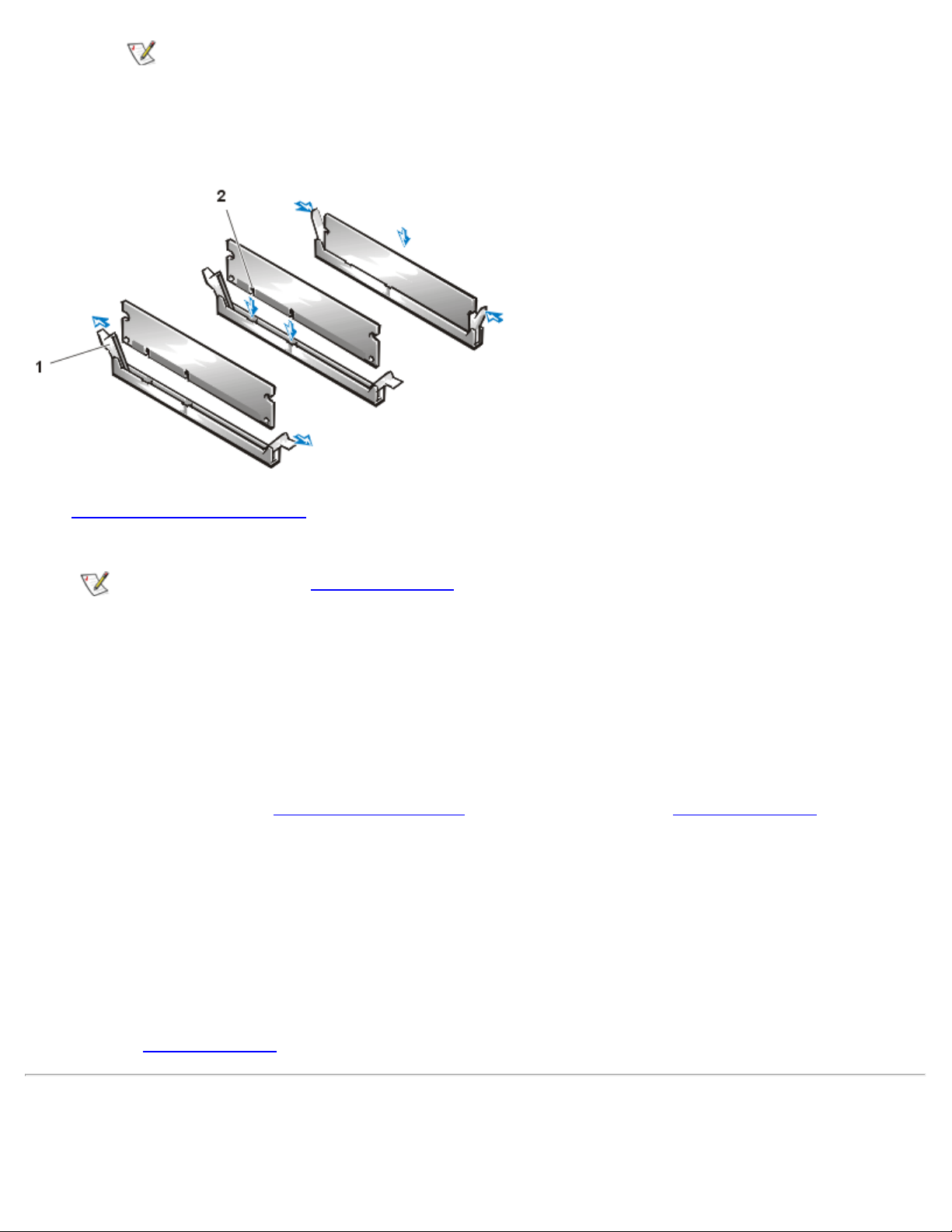
a. Locate the plastic securing clips at each end of the socket (see Figure 1
b. Press the clips outward until they snap open.
c. Align the two slots on the bottom of the DIMM with the two ridges inside the socket.
.
."
).
NOTE: Make sure to insert the bottom of the DIMM into the socket. The bottom of
the DIMM has two slots.
d. Press the DIMM straight into the slot running down the center of the socket until the
securing clips snap into place around the ends of the DIMM.
file:///C|/infodev/2013/eDoc/OpGX1/UG/memory.htm[2/21/2013 11:47:13 AM]
Page 37
System Memory: Dell OptiPlex GX1 Small-Form-Factor System User's Guide
NOTE: Press the top center of the DIMM, and then press the top corners of the
DIMM. This action firmly seats the DIMM in the socket, which allows the securing
clips to snap into place around the end of the DIMM.
Figure 1. Installing a DIMM
1 Securing clips (2)
2 Slots (2)
4. Replace the computer cover
, and reconnect your computer and peripherals to their electrical outlets
and turn them on.
NOTE: If Enabled, the Chassis Intrusion option will cause the following message to be displayed
at the next system start-up:
ALERT! Cover was previously removed.
The system detects that the new memory does not match the existing system configuration information
and generates the following message:
The amount of system memory has changed.
Strike the F1 key to continue, F2 to run the setup utility
5. Press <F2> to enter the System Setup program
, and check the value for System Memory.
The system should have already changed the value of System Memory to reflect the newly installed
memory modules. Verify the new total. If it is correct, skip to step 7.
6. If the memory total is incorrect, turn off and disconnect your computer and peripherals from their
electrical outlets. Remove the computer cover, and check the installed DIMMs to make sure that they
are seated properly in their sockets. Then repeat steps 4 and 5.
7. When the System Memory total is correct, press <Esc> to exit the System Setup program.
8. Run the Dell Diagnostics
to verify that the DIMMs are operating properly.
Removing DIMMs
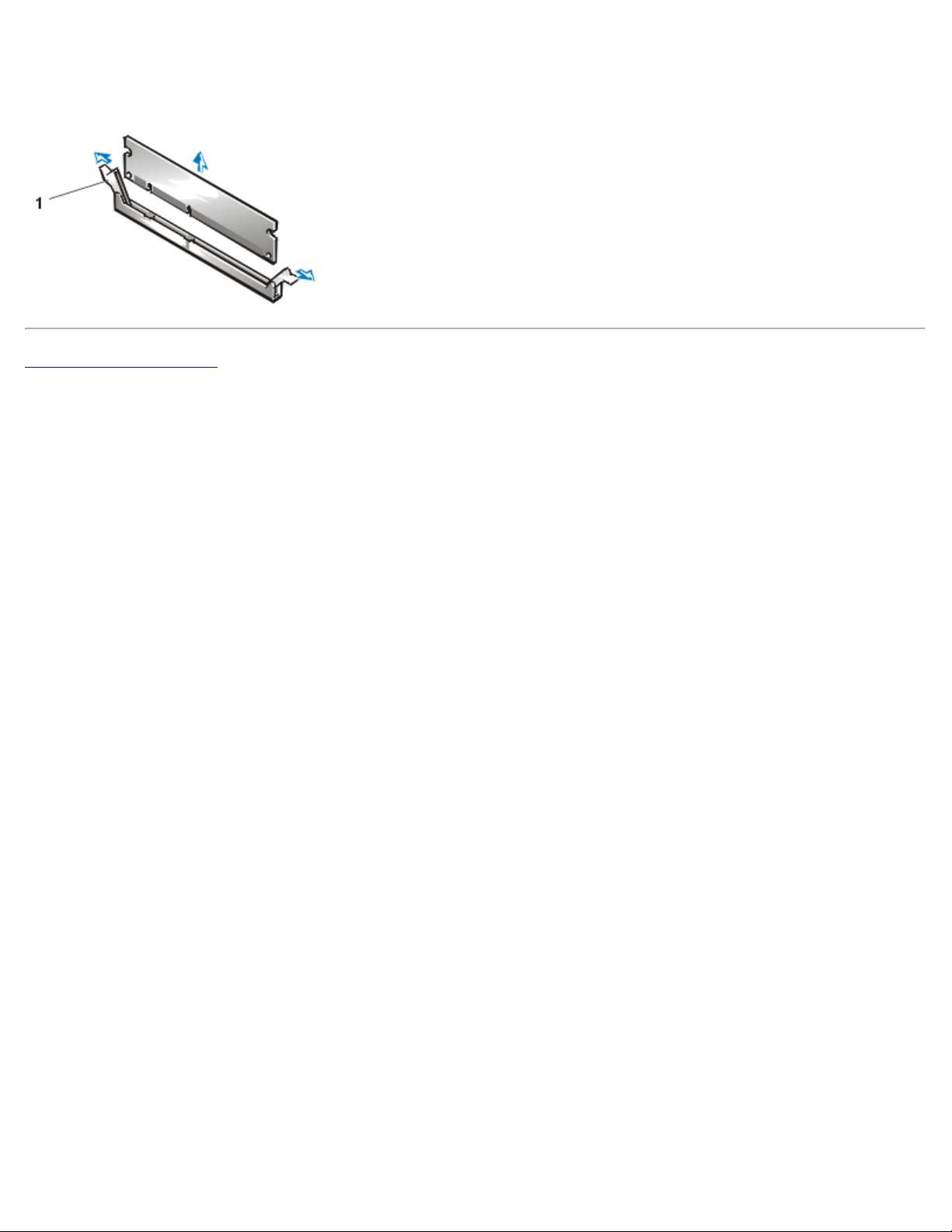
To remove a DIMM, press the securing clips outward simultaneously until the DIMM disengages from the
file:///C|/infodev/2013/eDoc/OpGX1/UG/memory.htm[2/21/2013 11:47:13 AM]
Page 38
System Memory: Dell OptiPlex GX1 Small-Form-Factor System User's Guide
socket (see Figure 2). It should pop out slightly.
Figure 2. Removing a DIMM
1 Securing clips (2)
Back to Contents Page
file:///C|/infodev/2013/eDoc/OpGX1/UG/memory.htm[2/21/2013 11:47:13 AM]
Page 39
Dell Diagnostics: Dell OptiPlex GX1 Small-Form-Factor System User's Guide
A menu category called Config that describes the configuration of the devices in the selected device
Back to Contents Page
Dell™ Diagnostics: Dell OptiPlex™ GX1 Small-Form-Factor System
User's Guide
Overview Confirming the System Configuration
Information
Features of the Dell Diagnostics How to Use the Menu
When to Use the Dell Diagnostics Main Menu Categories
Before You Start Testing Tests in the Dell Diagnostics
Starting the Dell Diagnostics Error Messages
How to Use the Dell Diagnostics
Overview
Unlike many diagnostic programs, the Dell Diagnostics helps you check your computer's hardware without
any additional equipment and without destroying any data. By using the diagnostics, you can have
confidence in your computer system's operation. And if you find a problem you cannot solve by yourself, the
diagnostic tests can provide you with important information you will need when talking to Dell's service and
support personnel.
NOTICE: Use the Dell Diagnostics to test only your Dell computer system. Using this program with
other computers may cause incorrect computer responses or result in error messages.
Features of the Dell Diagnostics
The Dell Diagnostics provides a series of menus and options from which you choose particular test groups or
subtests. You can also control the sequence in which the tests are run. The diagnostic test groups or
subtests also have these helpful features:
Options that let you run tests individually or collectively
An option that allows you to choose the number of times a test group or subtest is repeated
The ability to display or print out test results, or to save them in a file
Options to temporarily suspend testing if an error is detected, or to terminate testing when an
adjustable error limit is reached
A menu category called Devices that briefly describes each test and its parameters
file:///C|/infodev/2013/eDoc/OpGX1/UG/diag.htm[2/21/2013 11:47:14 AM]
Page 40

Dell Diagnostics: Dell OptiPlex GX1 Small-Form-Factor System User's Guide
group
Status messages that inform you whether test groups or subtests were completed successfully
Error messages that appear if any problems are detected
When to Use the Dell Diagnostics
Whenever a major component or device in your computer system does not function properly, you may have
a component failure. As long as the microprocessor and the input and output components of your computer
system (the monitor, keyboard, and diskette drive) are working, you can use the Dell Diagnostics. If you are
experienced with computers and know what component(s) you need to test, simply select the appropriate
diagnostic test group(s) or subtest(s). If you are unsure about how to begin diagnosing a problem, read the
rest of this section.
Before You Start Testing
Turn on your printer if one is attached, and make sure it is online. Also, you must create a copy of the Dell
Diagnostics on diskette.
1. Enter the System Setup program by restarting the computer and pressing <F2> when prompted.
2. Confirm that all ports are enabled, and make sure that the Boot Sequence option is set to CD-ROM
First.
3. Place the Dell ResourceCD in the CD-ROM drive, and press <Alt><b> to restart the system.
4. At the prompt, select the option to run the Dell Diagnostics.
5. Insert a blank diskette in drive A.
NOTE: Make sure that there is no data on the diskette that you want to keep. The diskette
creation process will destroy any data on the diskette.
6. At the prompt, select the option for the 16-bit Dell Diagnostics, and type y to continue.
The Dell Diagnostics diskette is created from the Dell ResourceCD.
7. Restart the computer, enter the System Setup program
First, and press <Alt><b> to reboot the system.
Your computer boots from the Dell Diagnostics diskette in drive A, and the Dell Diagnostics
automatically loads.
NOTE: At your first opportunity, make a working copy of the Dell Diagnostics diskette. Refer to your
operating system’s documentation for information on how to duplicate diskettes. Label both diskettes
as "Dell Diagnostics diskette," and put the original diskette away for safekeeping.
file:///C|/infodev/2013/eDoc/OpGX1/UG/diag.htm[2/21/2013 11:47:14 AM]
, change the Boot Sequence option to Diskette
Page 41

Dell Diagnostics: Dell OptiPlex GX1 Small-Form-Factor System User's Guide
Starting the Dell Diagnostics
Perform the following steps to start the diagnostics:
1. Turn on the system.
2. Enter the System Setup program
by restarting the computer and pressing <F2> when prompted.
3. Confirm that all ports are enabled. Also, make sure that the Boot Sequence option is set to Diskette
First.
4. Place your Dell Diagnostics diskette in the diskette drive, and press <Alt><b> to restart the system.
5. At the MS-DOS® prompt, type delldiag and press <Enter>.
NOTE: Before you read the rest of this section, you may want to start the Dell Diagnostics so that you
can see it on the screen of your monitor.
When you start the diagnostics, the Dell logo screen appears, followed by a message telling you that the
diagnostics is loading.
After the diagnostics loads, the Diagnostics Menu appears (see Figure 1). The menu allows you to run all
or specific diagnostic tests or to exit to the MS-DOS prompt.
For a quick check of your system, select the Run Quick Tests option. This option runs only the subtests that
do not require user interaction and that do not take a long time to run. Dell recommends that you choose this
option first to increase the odds of tracing the source of the problem quickly. For a thorough check of your
system, select the Run All Tests option. To check a particular area of your system, select the Run Specific
Tests option.
To select an option from this menu, highlight the option and press <Enter>, or press the key that corresponds
to the highlighted letter in the option you choose.
Figure 1. Diagnostics Menu
file:///C|/infodev/2013/eDoc/OpGX1/UG/diag.htm[2/21/2013 11:47:14 AM]
Page 42

Dell Diagnostics: Dell OptiPlex GX1 Small-Form-Factor System User's Guide
How to Use the Dell Diagnostics
When you select Run Specific Tests from the Diagnostics Menu, the main screen of the diagnostics
appears (see Figure 2
configuration of your computer system, and allows you to select categories from a menu. From this screen,
you can enter two other types of screens.
Information on the main screen of the diagnostics is presented in the following five areas:
Two lines at the top of the screen identify the version number of the Dell Diagnostics.
On the left side of the screen, the Available Test Group area lists the diagnostic test groups in the
order they will run if you select All from the Run menu category. Press the up- or down-arrow key to
highlight a test group.
On the right side of the screen, the System Configuration area lists the computer’s currently detected
hardware and some of the relevant settings.
The lower-right side of the screen displays information about your integrated drive electronics (IDE)
hard-disk and CD-ROM drive(s).
Two lines at the bottom of the screen make up the menu area. The first line lists the categories you can
select; press the left- or right-arrow key to highlight a menu category. The second line gives
information about the category currently highlighted.
). The main screen lists the diagnostic test groups, gives information about the
Figure 2. Dell Diagnostics Screen
file:///C|/infodev/2013/eDoc/OpGX1/UG/diag.htm[2/21/2013 11:47:14 AM]
Page 43
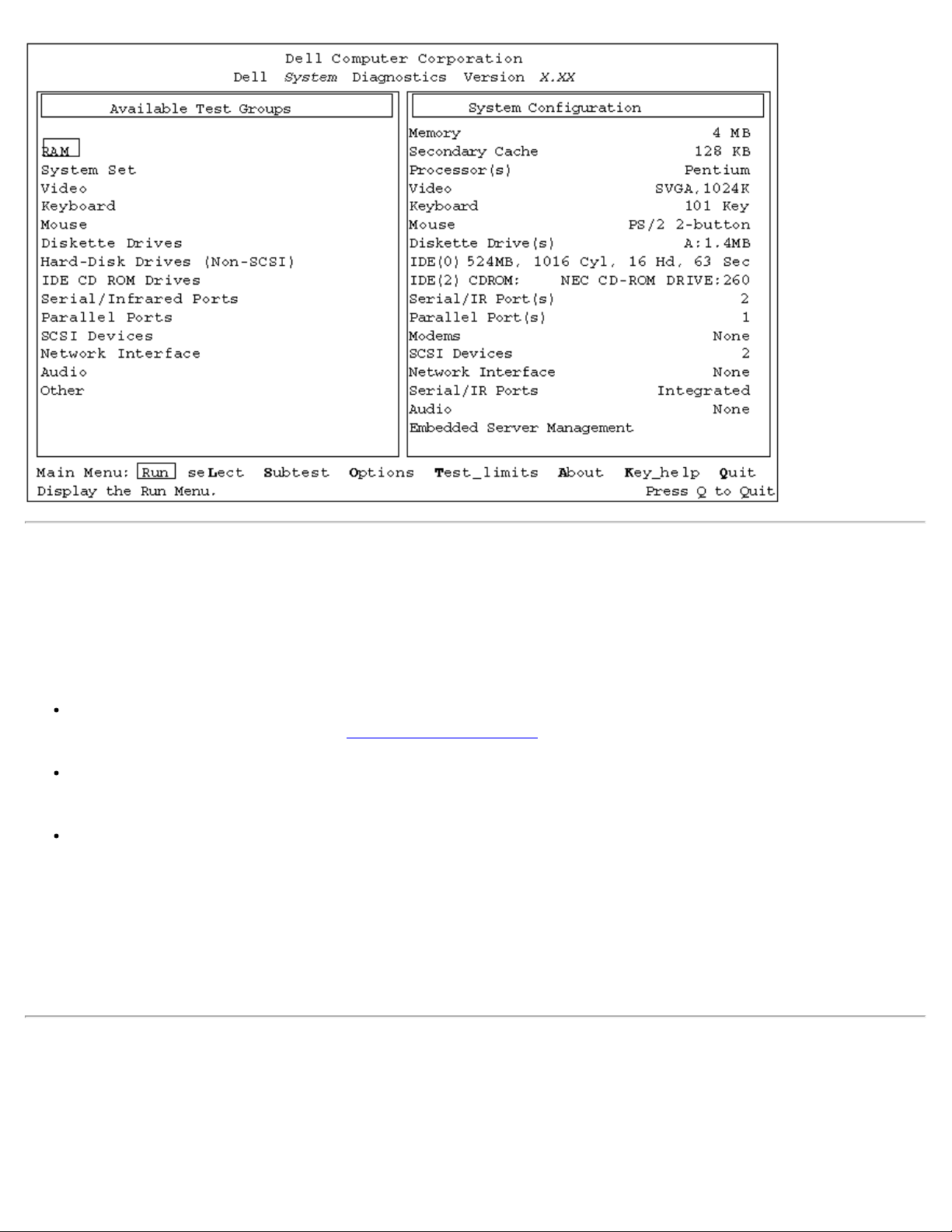
Dell Diagnostics: Dell OptiPlex GX1 Small-Form-Factor System User's Guide
Confirming the System Configuration Information
When you boot your system from the Dell ResourceCD, the diagnostics checks your system configuration
information and displays it in the System Configuration area on the main screen.
The following sources supply this configuration information for the diagnostics:
The system configuration information settings (stored in nonvolatile random-access memory [NVRAM])
that you selected while using the System Setup program
Identification tests of the microprocessor, the video controller, the keyboard controller, and other key
components
Basic input/output system (BIOS) configuration information temporarily saved in RAM
Do not be concerned if the System Configuration area does not list the names of all the components or
devices you know are part of your computer system. For example, you may not see a printer listed, although
you know one is attached to your computer. Instead, the printer is listed as a parallel port. The computer
recognizes the parallel port as LPT1, which is an address that tells the computer where to send outgoing
information and where to look for incoming information. Because your printer is a parallel communications
device, the computer recognizes the printer by its LPT1 address and identifies it as a parallel port.
How to Use the Menu
One of the menu categories is already highlighted. You can move the highlight from one category to another
by pressing the left- or right-arrow key. As you move from one menu category to another, a brief explanation
of the currently highlighted category appears on the bottom line of the screen.
file:///C|/infodev/2013/eDoc/OpGX1/UG/diag.htm[2/21/2013 11:47:14 AM]
Page 44

Dell Diagnostics: Dell OptiPlex GX1 Small-Form-Factor System User's Guide
If you want more information about a test group or subtest, move the highlight to the About option and press
The Quit Menu category returns you to the Main menu.
<Enter>. After reading the information, press the <Esc> key to return to the previous screen.
Main Menu Categories
Eight categories are listed in the Main menu of the diagnostics main screen: Run, Select, Subtest,
Options
There are two ways to select a menu category:
, Test Limits, About, Key-Help, and Quit.
NOTE: Before running any test groups or subtests (by selecting Run), you should consider setting
global parameters within the Options category. They offer you greater control over how the test
groups or subtests are run and how their results are reported.
Look on the screen to see which letter in the category is capitalized, and type that letter (for example,
type r to select the Run category).
Move the highlight to the category you wish to select by pressing the left- or right-arrow key, and then
press <Enter>.
Whenever one of the eight categories is selected, additional choices become available.
The following subsections explain the menu categories as listed from left to right in the Main menu.
Run
Run displays five categories: One, Selected, All, Key-Help, and Quit Menu. If you select One, all the
subtests within the highlighted test group are run. If you choose Selected, only the selected test groups or
the subtests that you selected within the test groups are run. If you select All, all of the subtests in all of the
test groups are run. (The test groups or subtests are run in the same order as they are listed.)
The Key-Help category displays a list of key controls available for the particular category you have chosen.
The Quit Menu category returns you to the Main menu.
Select
Select allows you to select individual test groups to tailor the testing process to your particular needs. You
can choose one or more test groups and run them sequentially or individually. When you choose Select, five
categories are displayed: All, One, Clear All, Key-Help, and Quit Menu.
To select all the test groups, press <Enter> when All is highlighted in the Select menu.
To select an individual test group, highlight the test group and press the spacebar or highlight One and press
<Enter>. Press the up- or down-arrow key to change the highlighted test group.
To reverse a test group selection, highlight the test group and press the spacebar. To clear all selections,
select Clear All.
The Key-Help category displays a list of key controls available for the particular category you have chosen.
file:///C|/infodev/2013/eDoc/OpGX1/UG/diag.htm[2/21/2013 11:47:14 AM]
Page 45

Dell Diagnostics: Dell OptiPlex GX1 Small-Form-Factor System User's Guide
Subtest
Most of the test groups consist of several subtests. Use the Subtest category to select individual subtests
within the test group(s).
When you select Subtest, many of the same categories as those on the Main menu are displayed: Run,
Select
, Options, Test Limits, About, Key-Help, and Quit Menu. Each of these categories is explained in
the following subsections.
Run Under Subtest
Run in the Subtest menu displays five categories: One, Selected, All, Key-Help, and Quit Menu. If
you select One, only the highlighted subtest is run. If you select Selected, only the selected subtests
are run. If you select All, all of the subtests listed on the screen are run. (The subtests are run in the
same order as they are listed.)
The Key-Help category displays a list of key controls available. The Quit Menu category returns you to
the previous menu.
Select Under Subtest
Select in the Subtest menu allows you to select individual subtests to tailor the testing process to your
particular needs. You can choose one or more subtests from the list. When you choose Select, five
categories are displayed: All, One, Clear All, Key-Help, and Quit Menu.
To select all the subtests, press <Enter> when All is highlighted in the Select menu. To select an
individual subtest, highlight the subtest and press the spacebar or highlight One and press <Enter>.
Press the up- or down-arrow key to highlight a subtest to be selected.
To reverse a subtest selection, highlight the subtest and press the spacebar. To clear all selections,
select Clear All.
The Key-Help category displays a list of key controls available. The Quit Menu category returns you to
the previous menu.
Options Under Subtest
The Options category in the Subtest menu functions the same way as the Options category in the
Main
menu. For information on this category, see "Options."
Test Limits Under Subtest
The Test Limits category in the Subtest menu functions the same way as the Test Limits category in
the Main
menu. For information on this category, see "Test Limits."
About Under Subtest
The About category in the Subtest menu displays information about the highlighted subtest.
Key-Help Under Subtest
file:///C|/infodev/2013/eDoc/OpGX1/UG/diag.htm[2/21/2013 11:47:14 AM]
Page 46

Dell Diagnostics: Dell OptiPlex GX1 Small-Form-Factor System User's Guide
The Key-Help category in the Subtest menu displays a list of key controls available.
Quit Menu Under Subtest
The Quit Menu category in the Subtest menu returns you to the Main menu.
Options
Table 1 lists all of the possible values for each global parameter of Options. A brief description of each
parameter follows the table. To change Options parameters, press the spacebar, the left- and right- arrow
keys, or the plus (+) and minus (-) keys.
Table 1. Option Parameters
Option Limit Possible Values
Number of Times to Repeat Test(s) 0001 through 9999, or 0000, which loops indefinitely until you
press the <Ctrl> and <Break> keys. The default is 1.
Maximum Errors Allowed 0000 through 9999, where 0000 means that there is no error limit.
The default is 1.
Pause For User Response Yes, No
Allows you to decide whether tests will wait for user input.
The default is Yes to wait for user input.
Output Device for Status Messages Display, Printer, File
If you have a printer attached to your computer, you can use it to
print the status messages, if any, that are generated when a test
runs. (The printer must be turned on and in the online mode to
print.) If you select File, the messages are printed to a file named
result on a diskette that you insert into drive A when prompted. If
you are running the diagnostics from a utility partition on your
hard-disk drive, the result file is created on the hard-disk drive.
The default is Display.
Output Device for Error Messages Display, Printer, File
This parameter has the same effect as the Output Device for
Status Messages parameter, except that it pertains only to error
messages. The default is Display.
Number of Times to Repeat Test(s)
This parameter specifies the number of times the tests run when you select Run. To change the
default, type in the desired value. If you type 0 (zero), the tests will run indefinitely.
Maximum Errors Allowed
This parameter specifies the maximum number of errors that can occur before testing is stopped. The
error count begins from zero each time you run a subtest or test group individually or each time you
select All to run all of them. To change the default, type in the desired value. If you type 0 (zero), you
file:///C|/infodev/2013/eDoc/OpGX1/UG/diag.htm[2/21/2013 11:47:14 AM]
Page 47

Dell Diagnostics: Dell OptiPlex GX1 Small-Form-Factor System User's Guide
are specifying that there be no limit on the number of errors that can occur—testing will not be stopped,
The result file is an ordinary ASCII text file. You can access and review the result file as described in
regardless of the number of errors.
Pause for User Response
If this parameter value is set to Yes, the diagnostics pauses when one of the following occurs:
Your interaction is needed to verify the Video Test Group screens or the Keyboard Test Group
key functions or other types of interaction such as inserting a diskette.
The maximum error limit is reached.
If the Pause parameter is set to No, the diagnostics ignores some subtests that require your
interaction; certain subtests can run only if this option is set to Yes because they require user
interaction. Use the Pause parameter in situations where you may want to prevent subtests that require
user interaction from running—such as when you run the diagnostics overnight.
Output Device for Status Messages
Ordinarily, all status messages appear only on the screen. This parameter allows you to direct status
messages to either a printer or a file, in addition to the screen. If you choose the File option, status
messages are written to a file named result. This file is automatically created on a diskette that you
insert into drive A when prompted. If you are running the diagnostics from a utility partition on your
hard-disk drive, the result file is created on the hard-disk drive. If the result file already exists, new
status messages are added to it.
The result file is an ordinary American Standard Code for Information Interchange (ASCII) text file that
you can open in any text viewer or word processor. You can also access the result file with the MSDOS type command as follows:
1. Select Quit to exit the diagnostics and return to the operating system prompt.
2. At the operating system prompt, type the appropriate command and press <Enter>:
type result
The contents of the file appear on the screen.
After running particular diagnostic tests and viewing the status messages generated by the tests in the
result file, you can erase the contents of the file so that it is clear for the next set of messages
generated. Otherwise, the next messages are added at the end of the previous ones in the file.
Output Device for Error Messages
Ordinarily, all error messages appear only on the screen. This parameter allows you to direct error
messages to either a printer or a file, in addition to the screen. If you choose the File option, error
messages are written to the result file used for status messages. This file is automatically created on a
diskette that you insert into drive A when prompted. If you are running the diagnostics from a utility
partition on your hard-disk drive, the result file is created on the hard-disk drive. If the result file
already exists, new error messages are added to it.
file:///C|/infodev/2013/eDoc/OpGX1/UG/diag.htm[2/21/2013 11:47:14 AM]
Page 48

Dell Diagnostics: Dell OptiPlex GX1 Small-Form-Factor System User's Guide
the previous subsection, "Output Device for Status Messages."
After running particular diagnostic tests and viewing the error messages generated by the tests in the
result file, you can erase the contents of the file so that it is clear for the next set of messages
generated. Otherwise, the next messages are added at the end of the previous ones in the file.
Test Limits
NOTE: The Dell Diagnostics sets default limits on all tests. The only reason to change the default
would be to limit the amount of testing done.
The RAM Test Group, the Video Test Group, the Diskette Drives Test Group, the IDE (ATA/ATAPI)
Devices Test Group, the Serial/Infrared Ports Test Group, the Parallel Ports Test Group, and the SCSI
Devices Test Group allow you to designate limits. Whether you select Test Limits for a highlighted test
group (from the Main
menu) or a subtest (from the Subtest menu), you set the limits for all the subtests in
that test group. When you select Test Limits, a new screen appears and the Key-Help area lists keys to use
with the new screen. Press <Page Down> to select the next menu or submenu. Press <Esc> to return to the
main Test Limits window.
How you change a value for the limits of a test group or subtest depends on the type of parameter
associated with it. Different keys are used to change values for different types of parameters. For example,
memory address limits specified for the RAM Test Group
are changed by typing in numbers over the digits
of a given limit or by pressing the plus (+) or minus (-) keys to increase or decrease the given limit. In
contrast, to set limits for the Serial/Infrared Ports Test Group
, you use the spacebar to toggle between Yes
and No.
After you are satisfied with the limits, return to the Dell Diagnostics main screen by pressing <Esc>. The
values you selected under Test Limits remain in effect during all the test groups or subtests you run, unless
you change them. However, the values are reset to their defaults when you restart the diagnostics.
About
About in the Main
menu lists all of the subtests for the selected test group and displays information about
the subtest that is highlighted.
Key-Help
Key-Help always displays a list of key controls available for the particular category you have selected.
Quit
Selecting Quit from the Main
menu exits the diagnostics and returns you to your operating system
environment.
After you return to the operating system environment, remove your diagnostics diskette from drive A and
reboot the computer.
NOTICE: It is important that you quit the diagnostics correctly because the program writes data to the
computer’s memory that can cause problems unless properly cleared.
file:///C|/infodev/2013/eDoc/OpGX1/UG/diag.htm[2/21/2013 11:47:14 AM]
Page 49
Dell Diagnostics: Dell OptiPlex GX1 Small-Form-Factor System User's Guide
to process a simple set of memory-
Tests in the Dell Diagnostics
To troubleshoot components or devices, run the appropriate test (test group or subtest) in the diagnostics on
your diagnostics diskette. The diagnostics exercises the functional components and devices of your
computer system more vigorously and thoroughly than they are exercised during normal operation. The
diagnostics is organized by components into test groups and subtests within each test group. Each subtest is
designed to detect any errors that may interfere with the normal operation of a specific device of the
computer.
NOTE: Some subtests requiring hardware not listed in the System Configuration area of the
diagnostics screen appear to run, but they conclude with a status message stating Component not
present (or disabled).
The diagnostic test groups, their subtests, and comments concerning their use are listed in Table 2.
Table 2. Dell Diagnostic Test Groups and Subtests
Test Group Subtest Comment
RAM Quick Memory Test
Comprehensive Memory Test
Secondary Cache Memory Test
System Set
CMOS Confidence Test
CMEM Confidence Test
DMA Controller Test
Real-Time Clock Test
System Timers Test
Interrupt Controller Test
Reset Button Test
System Speaker Test
Coprocessor Calculation Test
Coprocessor Error Exception Test
PC Card Controller Test
Thermal Control Test
Tests the RAM and cache. (Some
computers include expanded or
extended memory; all memory is
tested.)
Tests the system board’s support
chips, DMA controller, computer timer,
NVRAM, speaker controller, cache, and
EISA configuration RAM chip, as
appropriate.
Tests the math coprocessor that is
internal to the microprocessor.
Tests the PC Card controller on the
system board.
Checks the functionality of the thermalmonitoring and microprocessor speedswitching device on the system board.
Multiprocessor Test
USB Register Test
USB Memory Structure Test
file:///C|/infodev/2013/eDoc/OpGX1/UG/diag.htm[2/21/2013 11:47:14 AM]
For systems with multiprocessors,
confirms that the secondary
microprocessor is operational.
Checks the onboard registers of the
USB interface. This subtest does not
test USB peripherals.
Monitors the ability of a USB controller
Page 50
Dell Diagnostics: Dell OptiPlex GX1 Small-Form-Factor System User's Guide
resident instructions.
Video Video Memory Test
Video Hardware Test
Text Mode Character Test
Text Mode Color Test
Text Mode Pages Test
Graphics Mode Test
Color Palettes Test
Solid Colors Test
Keyboard
Keyboard Controller Test
Keyboard Key Sequence Test
Keyboard Interactive Test
Stuck Key Test
External Key Pad Test
Mouse
Diskette
Drives
Mouse Tests the electronic pointing device
Change Line Test
Seek Test
Read Test
Write Test
Tests the video subsystem and monitor
by checking various aspects of video
output.
Tests the keyboard by checking the
keyboard controller and by finding keys
that stick or respond incorrectly.
(bus mouse, serial mouse, trackball, or
PS/2 mouse).
Tests a drive that uses removable
diskettes (3.5-inch or 5.25-inch). Also
tests the associated interface.
IDE
(ATA/ATAPI)
Devices
Serial/Infrared
Ports
Parallel Ports
Display Information
Confidence Test
Self Diagnostics Test
Seek Test
Read Test
Verify Test
Write Test
SMART Test
CD-ROM Audio Test
Media Eject Test
Tape Retension Test
Serial/Infrared Baud Rate Test
Serial/Infrared Interrupt Test
Serial/Infrared Internal Transmission Test
Serial External Transmission Test
Parallel Internal Test
Parallel External Loopback Test
Parallel External Interrupt Test
Parallel Printer Pattern Test
Tests drives connected to the system
IDE bus, including hard-disk drives and
removable media drives such as CDROM and tape drives.
Tests the components through which
peripherals that use the serial or
infrared ports, such as printers and
communications devices, send and
receive data.
Tests the components through which
peripherals that use the parallel port,
such as printers and communications
devices, send and receive data.
SCSI Devices
Internal Diagnostic
Seek Test
Read Test
Write Test
Audio Output Test
file:///C|/infodev/2013/eDoc/OpGX1/UG/diag.htm[2/21/2013 11:47:14 AM]
Tests any installed SCSI host adapters
and all the SCSI devices attached to
them. Also can be used to remove CDs
and tape cartridges from SCSI devices
and to display information about the
Page 51
Dell Diagnostics: Dell OptiPlex GX1 Small-Form-Factor System User's Guide
Eject Removable Media
types of SCSI devices installed and the
Display Information
Network
Interface
Registers Test
Internal Loopback Test
External Loopback Test
Shared RAM Test
Display Information
Audio
Software Reset Test
Compatibility ID Test
Interrupt Test
DMA Test
FIFO RAM Test
Initial Reset Status Test
Internal Register Test
Dual Channel Test
FM Sound Playback Test
Analog Sound Playback Test
Record and Playback Test
System
Management
BIOS
BIOS Information
Environment Information
I/O Information
Memory Information
Processor Information
System Information
resources allocated to them.
Tests the read and write access
capability to the NIC registers. Also
tests the ability of the NIC to transmit
and receive data.
Tests the operation of the audio chip
set.
Tests the record and playback ability
of the internal microphone and
speakers.
Tests the state of various system
devices, such as the temperature of the
processor. Also displays system
management information for various
system devices.
RAM Test Group
The RAM Test Group subtests check all the directly addressable RAM.
The RAM Test Group program has parameters for the subtests that you can set: Test Limits and Options.
Three subtests are available for RAM: the Quick Memory Test, the Comprehensive Memory Test, and the
Secondary Cache Memory Test. The Quick Memory Test performs an address check to determine
whether the computer is properly setting and clearing individual bits in RAM and whether the RAM read and
write operations are affecting more than one memory address location at one time. This subtest checks all
available RAM. The Comprehensive Memory Test also performs an address check, as well as the
following:
Data pattern checks, to look for RAM bits that are stuck high or low, short-circuited data lines, and
some data pattern problems that are internal to the memory chips
A parity check that verifies the ability of the memory subsystem to detect errors
A refresh check, to verify that the dynamic RAM (DRAM) is being recharged properly
The Secondary Cache Memory Test confirms the functionality of the computer’s cache controller chip and
the cache memory.
file:///C|/infodev/2013/eDoc/OpGX1/UG/diag.htm[2/21/2013 11:47:14 AM]
Page 52

Dell Diagnostics: Dell OptiPlex GX1 Small-Form-Factor System User's Guide
Why Run a RAM Test?
Faulty memory can cause a variety of problems that may not, at first glance, appear to be happening in RAM.
If your computer is displaying one or more of the following symptoms, run the subtests in the RAM Test
Group to verify that the memory is not at fault:
A program is not running as usual, or a proven piece of software appears to malfunction and you
confirm that the software itself is not at fault. (You can confirm that the software is functioning properly
by moving it to another computer and running it there.)
Your computer periodically locks up (becomes unusable and must be rebooted), especially at different
places and times in different programs.
You get parity errors (any error message that contains the word parity) at any time during operation.
These errors are usually accompanied by a reference to an address—the location of the portion of
memory where the error occurred—which you should record on a copy of the Diagnostics Checklist
System Set Test Group
.
The subtests in the System Set Test Group check the computer’s basic system board components and
verify their related functions.
The subtests that constitute the System Set Test Group and the computer functions they confirm follow:
CMOS Confidence Test
Checks the NVRAM for accessibility and reliability of data storage by performing a data pattern
check and verifying the uniqueness of memory addresses.
CMEM Confidence Test
Verifies the accessibility and reliability of the 8 kilobytes (KB) of RAM on the Extended IndustryStandard Architecture (EISA) Configuration RAM chip, which stores the EISA hardware
configuration information. On systems without flash RAM, performs a data pattern and address
uniqueness test.
NOTE: This test applies only to systems with an EISA bus.
DMA Controller Test
Tests the direct memory access (DMA) controller and verifies the correct operation of its page
and channel registers by writing patterns to the registers.
Real-Time Clock Test
Confirms the functionality and accuracy of the computer’s real-time clock (RTC).
System Timers Test
Checks the timers used by the microprocessor for event counting, frequency generation, and
other functions. Only the functions that can be activated by software are tested.
file:///C|/infodev/2013/eDoc/OpGX1/UG/diag.htm[2/21/2013 11:47:14 AM]
Page 53

Dell Diagnostics: Dell OptiPlex GX1 Small-Form-Factor System User's Guide
Interrupt Controller Test
Generates an interrupt on each interrupt request (IRQ) line to verify that devices using that line
can communicate with the microprocessor and that the interrupt controllers send the correct
memory addresses to the microprocessor.
Reset Button Test
Confirms that the reset button works.
System Speaker Test
Checks the functionality of the speaker by generating eight tones.
Coprocessor Calculation Test
Checks the use of different types of numbers and the math coprocessor’s ability to calculate
correctly.
Coprocessor Error Exception Test
Verifies the math coprocessor’s ability to handle errors and to send IRQs to the microprocessor.
PC Card Controller Test
Tests the functionality of the PC Card controller on the system board.
Thermal Control Test
Checks the functionality of the thermal-monitoring and microprocessor speed-switching device on
the system board.
Multiprocessor Test
For systems with multiprocessors, confirms that the secondary microprocessor is operational.
USB Register Test
Checks the onboard registers of the Universal Serial Bus (USB) interface. This subtest does not
test USB peripherals.
USB Memory Structure Test
Monitors the ability of a USB controller to process a simple set of memory-resident instructions.
Why Run a System Set Test?
The System Set subtests double-check many system board components, such as the computer’s
input/output (I/O) circuitry, that are tested by other test groups or subtests in the diagnostics. You should run
the System Set Test Group if you are having a problem and cannot isolate the failure or malfunction to a
particular system board component.
The System Set Test Group also verifies the proper operation of other computer components, such as the
speaker, that are not tested elsewhere in the Dell Diagnostics.
file:///C|/infodev/2013/eDoc/OpGX1/UG/diag.htm[2/21/2013 11:47:14 AM]
Page 54

Dell Diagnostics: Dell OptiPlex GX1 Small-Form-Factor System User's Guide
The following symptoms usually suggest a problem with a component or subassembly that warrants running
a System Set subtest:
A program is not running as usual, or a proven piece of software appears to malfunction and you
confirm that the software itself is not at fault. (You can confirm that the software is functioning properly
by moving it to another computer and running it there.)
An option card you previously accessed can no longer be accessed.
You get parity errors or page fault failures (any error message that contains the word parity or page
fault) at any time during operation. These errors are usually accompanied by a reference to an
address, which you should record on a copy of the Diagnostics Checklist
.
Correcting errors in the system configuration information in the System Setup program does not resolve
a problem.
The computer’s clock/calendar stops.
The speaker no longer functions. The problem could be a failure of the system timers as well as a
failure of the speaker itself. Run the System Timers Test, followed by the System Speaker Test.
If a peripheral device appears to malfunction, run the Interrupt Controllers Test.
A spreadsheet program or other type of mathematical application runs abnormally slow, generates
error messages concerning calculations or operations, runs incorrectly, or generates incorrect results,
or a proven piece of the program appears to malfunction and you confirm that the software itself is not
at fault. (You can confirm that the software is not at fault by moving the program to another computer
and running it there.)
The computer periodically locks up, especially at different places and times in different programs.
The computer halts in the middle of performing calculations or complex mathematical operations.
Video Test Group
The subtests in the Video Test Group verify the proper operation of the video controller and the video
control circuitry installed in your computer. These subtests check for the correct operation of the readable
registers in the video circuitry and the controller. They write, read, and verify data patterns in the cursor
registers of the controller. The Video Test Group also tests all the video memory and provides additional
subtests to test the color features of a color monitor.
The eight subtests in the Video Test Group confirm the following video functions:
Video Memory Test
Checks the read/write capability of video memory in various video modes.
Video Hardware Test
Checks the cursor registers and the horizontal and vertical retrace bit registers in the video
controller.
file:///C|/infodev/2013/eDoc/OpGX1/UG/diag.htm[2/21/2013 11:47:14 AM]
Page 55

Dell Diagnostics: Dell OptiPlex GX1 Small-Form-Factor System User's Guide
Text Mode Character Test
Checks the video subsystem’s ability to present data in text modes.
Text Mode Color Test
Checks the video subsystem’s ability to present color in text modes.
Text Mode Pages Test
Checks the video subsystem’s ability to map and present all available video pages on the screen,
one page at a time.
Graphics Mode Test
Checks the video subsystem’s ability to present data and color in graphics modes.
Color Palettes Test
Checks the video subsystem’s ability to display all of the available colors.
Solid Colors Test
Checks the video subsystem’s ability to show screens full of solid colors. Allows you to check for
missing color subpixels.
Many of these tests display characters or graphics on the screen for you to verify. Samples of these screens
are shown in "Diagnostics Video Tests."
NOTE: The default limit for testing super video graphics array (SVGA) modes is No. If you are testing
an external monitor, change the default to Yes.
Why Run a Video Test?
Many of the symptoms that would prompt you to run a subtest in the Video Test Group are obvious,
because the monitor is the visual component of your computer system. Before you run the Video Test
Group or any of its subtests, you should make sure that the problem is not in your software or caused by a
hardware change. You should also try running all of the software support utilities provided for the monitor
and the video subsystem.
If the following symptoms still occur, run the appropriate test(s) as follows:
If your monitor shows a partially formed or distorted image, run all of the subtests in the Video Test
Group.
If the alignment of text or images is off, regardless of the program you are running, run the Text Mode
Character Test, Text Mode Pages Test, and Graphics Mode Test.
If you have a color monitor or a program that runs in color, but the color is intermittent or not displayed
at all, run the Text Mode Color Test, Color Palettes Test, and Solid Color Test.
If your monitor malfunctions in one mode but works fine in another (for example, text is displayed
correctly, but graphics are not), run the Text Mode Character Test, Text Mode Color Test, Text
file:///C|/infodev/2013/eDoc/OpGX1/UG/diag.htm[2/21/2013 11:47:14 AM]
Page 56

Dell Diagnostics: Dell OptiPlex GX1 Small-Form-Factor System User's Guide
Mode Pages Test, and Graphics Mode Test.
Keyboard Test Group
The subtests in the Keyboard Test Group verify the correct operation of your keyboard and the keyboard
controller chip.
The five keyboard subtests confirm the following keyboard functions:
Keyboard Controller Test
Confirms the ability of the keyboard controller chip to communicate with the keyboard and the
programming of the controller chip
Keyboard Key Sequence Test
Verifies that the keys on the keyboard function correctly when you press the keys in a predefined
order
Keyboard Interactive Test
Checks the internal microcode of the keyboard and the external interface of the keyboard
controller chip for a malfunctioning key
Stuck Key Test
Checks the internal microcode of the keyboard and the external interface of the keyboard
controller chip for a repeating key signal
External Key Pad Test
Checks the contact beneath the key for an electrical impulse to ensure that the key is working
properly
Why Run a Keyboard Test?
Keyboard problems are not always caused by the keyboard. For example, a complete lockup of the computer
system, rendering the keyboard inoperable, is more likely caused elsewhere. There are three symptoms that
are likely to be keyboard-related. Sometimes, the configuration of a program changes the function of a key or
key combination. Likewise, key configuration programs such as ProKey can change a key’s function.
Because these programs are memory resident, you should be sure to clear them out of your computer’s
memory before running a subtest in the Keyboard Test Group. (Clear them from memory by booting your
computer from the diagnostics diskette.) When these possibilities have been eliminated, and if the following
symptoms occur, you should run one or more of the subtests in the Keyboard Test Group:
When you press a key, the character represented by that key appears repeatedly; the key seems to be
stuck. Run the Stuck Key Test.
When you press a key and the response is different from the usual response or the response you
anticipated, the key contact may be damaged. Run the Keyboard Interactive Test.
When a key does not work at all, run all of the subtests in the Keyboard Test Group.
file:///C|/infodev/2013/eDoc/OpGX1/UG/diag.htm[2/21/2013 11:47:14 AM]
Page 57

Dell Diagnostics: Dell OptiPlex GX1 Small-Form-Factor System User's Guide
Mouse Test
The Mouse Test checks the functionality of the mouse controller (which coordinates cursor movement on the
screen with corresponding movement of your mouse or touch pad) and the operation of the mouse
keys/touch pad.
There are no subtests for the Mouse Test Group.
Why Run the Mouse Test?
Mouse or touch pad problems are as likely to originate in RAM as they are to be caused by a faulty mouse or
touch pad. Three sources of RAM-related problems include the configuration of a program (which changes
the function of the mouse or touch pad), memory-resident programs such as Sidekick or ProKey, and failure
of a device driver (the software that controls the function of the mouse or touch pad). If these possibilities
have been eliminated and the following symptoms persist, run the Mouse Test:
When you press a mouse button or the touch pad, the function of the button (or touch pad) continues;
that is, the button (or touch pad) seems to be stuck.
If the response when you press a mouse button or the touch pad is different from the usual or
anticipated response, the button (or touch pad) contact may be damaged.
A mouse button or the touch pad does not work at all.
The cursor does not respond on the screen in accordance with the movements you make with the
mouse or touch pad.
Diskette Drives Test Group
The subtests in the Diskette Drives Test Group allow you to test both 5.25-inch and 3.5-inch diskette drives
of all capacities.
The four diskette drive subtests available in the Diskette Drives Test Group confirm the following drive
functions:
Change Line Test
Checks for bent pins on the diskette drive controller and for defective lines on the diskette cable
Seek Test
Checks the drive’s ability to search for a specified track on the diskette and to position its
read/write heads to all tracks
Read Test
Positions the read/write heads at each cylinder of the diskette for reading data and verifies that all
tracks on the diskette can be read correctly
Write Test
Positions the read/write heads at each cylinder of the diskette and verifies that all tracks on the
file:///C|/infodev/2013/eDoc/OpGX1/UG/diag.htm[2/21/2013 11:47:14 AM]
Page 58

Dell Diagnostics: Dell OptiPlex GX1 Small-Form-Factor System User's Guide
diskette can be written to correctly
Why Run a Diskette Drives Test?
Very often, a diskette drive problem may first appear to be a diskette problem. A box of defective diskettes
might produce faulty-drive error messages. The test results can be confusing, so Dell suggests running the
subtests in the Diskette Drives Test Group more than once using diskettes from different sources.
Another possible cause of diskette drive problems is human error—typing a command in an incorrect form
(usually called a syntax error). Be sure you have entered the command in the proper form.
When the diskette(s) and command syntax are eliminated as causes, the following symptoms usually
suggest a drive problem and warrant running a subtest in the Diskette Drives Test Group:
An error message appears on the screen stating that the computer cannot read from or write to a
diskette.
A diskette cannot be properly formatted, or format error messages appear on the screen.
Data on diskettes is corrupted or lost; these problems may be intermittent.
IDE (ATA/ATAPI) Devices
The subtests in the IDE (ATA/ATAPI) Devices Test Group check the functionality of all drives connected to
the system IDE bus, including hard-disk and removable media drives. Some of the subtests listed in this
section apply only to particular types of drives, such as the Tape Retension Test, which applies only to tape
drives.
The eleven subtests in the IDE (ATA/ATAPI) Devices Test Group confirm the following drive functions:
Display Information
Displays information about any drives connected to the IDE bus.
Confidence Test
Runs a quick test on any hard-disk drives to ensure that they are operating properly.
Self Diagnostics Test
Uses the drive's internal test capability to determine whether the drive is functioning properly.
Seek Test
Checks the drive's ability to search for each block on the device.
Read Test
Positions the read heads at each block of the device for reading data and verifies that all blocks on the
device can be read correctly.
Verify Test
file:///C|/infodev/2013/eDoc/OpGX1/UG/diag.htm[2/21/2013 11:47:14 AM]
Page 59

Dell Diagnostics: Dell OptiPlex GX1 Small-Form-Factor System User's Guide
Similar to the Read Test, but no data is transferred from the drive to the system.
Write Test
Positions the read/write heads at each block of the drive and verifies that all tracks on the drive can be
written to correctly.
SMART Test
Checks to see if a hard-disk drive's internal error thresholds have been exceeded, which might predict
impending hard-disk drive failure. If any thresholds have been exceeded, the test fails.
CD-ROM Audio Test
Attempts to play an audio track from a CD in a CD-ROM drive. If the system does not have speakers
and an integrated audio controller or sound card, you must connect headphones to the CD-ROM
headphone jack to verify whether the test completes successfully.
Media Eject Test
Attempts to electronically eject media from a removable media drive. If the drive does not support
electronic media ejection, the test is meaningless.
Tape Retension Test
Performs a tape retension operation on a tape drive with a tape cartridge installed. Tape drive errors
are sometimes due to a cartridge that needs to be retensioned.
Why Run an IDE (ATA/ATAPI) Devices Test?
NOTE: If you check your hard-disk drive to determine the amount of available space, your operating
system will probably report problem areas. Problem areas on hard-disk drives are common because
most hard-disk drives have a small amount of space that is not usable. The hard-disk drive keeps a
record of this space so that your computer will not attempt to use it. Identification of unusable disk
space, unless it is an unusually large amount (over five percent of the possible total), should not be
regarded as a cause for testing the hard-disk drive.
These are the most common symptoms that might prompt you to test an IDE drive:
The drive fails during the boot routine.
Seek errors are reported by the operating system or application programs.
An error message appears on the screen stating that the computer cannot read from or write to the
drive.
Data on the drive is corrupted or lost; this problem may be intermittent. Once saved by a program, files
cannot be properly recalled.
Serial/Infrared Ports Test Group
The subtests in the Serial/Infrared Ports Test Group check the computer’s interface with external devices,
file:///C|/infodev/2013/eDoc/OpGX1/UG/diag.htm[2/21/2013 11:47:14 AM]
Page 60

Dell Diagnostics: Dell OptiPlex GX1 Small-Form-Factor System User's Guide
such as a printer and a mouse, that are connected to the computer through a serial or infrared port. The
subtests in this test group are not intended as a diagnostic test for the actual peripheral attached to each
port.
NOTES: With certain modems installed, the Serial/ Infrared Ports Test Group subtests may fail
because the modem appears to the Dell Diagnostics as a serial or infrared port, but it cannot be
tested as a serial or infrared port. If a modem is installed and one of the serial/ infrared ports subtests
fails, remove the modem and run the diagnostic tests again.
If an external loopback connector is not attached to a serial or infrared port, the Serial External
Transmission Test will fail for that port and the results of this test should therefore be ignored. An
external modem connected to the port does not substitute for an external loopback connector.
The four subtests in the Serial/Infrared Ports Test Group confirm the following port functions:
Serial/Infrared Baud Rate Test
Checks the baud rate generator in each serial communications chip against the computer’s clock
Serial/Infrared Interrupt Test
Checks the serial port’s ability to send IRQs to the microprocessor
Serial/Infrared Internal Transmission Test
Checks several internal functions of the serial port using the internal loopback mode of the serial
communications chip
Serial External Transmission Test
If a loopback device is attached, checks the line control bits of the serial port and sends a test
pattern at several baud rates, checking the returned values
Why Run a Serial/Infrared Ports Test?
If the Dell Diagnostics does not recognize your computer’s serial or infrared ports, enter the System Setup
program and check the Serial/infrared Port category to see whether the port has been disabled. The
subtests in the Serial/Infrared Ports Test Group cannot test a port unless it is enabled.
When a port is faulty, it may not be immediately evident that the port, and not the device connected to the
port, is faulty. Instead, the peripheral (such as a printer or mouse) might behave erratically or not operate at
all. If the external device is not properly installed through your software, it also may not function properly. Try
operating the peripheral from different programs or through the operating system. If it still does not work, you
can eliminate the software configuration as the cause of the problem.
Another possible cause for errors is the external device. Use the documentation that came with the
peripheral to troubleshoot it and confirm that it is working properly. (Most printers have a self-test.)
After you eliminate incorrect system configuration information settings, peripheral malfunctions, and software
errors as potential causes of port problems, you can run the subtests in the Serial/Infrared Ports Test
Group to check your hardware. Although the following symptoms can be caused by faulty peripherals or
software errors, they might also suggest a port problem:
file:///C|/infodev/2013/eDoc/OpGX1/UG/diag.htm[2/21/2013 11:47:14 AM]
Page 61

Dell Diagnostics: Dell OptiPlex GX1 Small-Form-Factor System User's Guide
If a peripheral works intermittently or produces intermittent errors, the port may be faulty.
If the computer displays an error message that is related to the external device connected to a port, but
corrections to the device do not resolve the error, run the appropriate subtest in the Serial/Infrared
Ports Test Group.
If your software and the diagnostics do not recognize that you have a serial or infrared port, you should
check the Serial/Infrared Port category in the System Setup program
, and if necessary, run the
appropriate subtest in the Serial/Infrared Ports Test Group.
Parallel Ports Test Group
The subtests in the Parallel Ports Test Group check the computer’s interface with external devices, such as
a printer, that are connected to the computer through a parallel port. The subtests in this test group are not
intended as a diagnostic test for the actual peripheral attached to each port. (The only exception is a printer,
as described in the Parallel Internal Test.)
NOTE: If an external loopback connector is not attached to the parallel port, the Parallel External
Loopback Test will fail for that port and the results of this test should therefore be ignored.
The four subtests in the Parallel Ports Test Group confirm the following port functions:
Parallel Internal Test
Checks several internal functions of the parallel port
Parallel External Loopback Test
Tests the functionality of the control lines through an external loopback connector, if an external
loopback connector is available
Parallel External Interrupt Test
Tests the parallel port’s ability to generate interrupts from all possible sources, if an external
loopback connector or printer is available
Parallel Printer Pattern Test
Tests a printer and tests the parallel port’s ability to send a pattern to the printer, if connected
Why Run a Parallel Ports Test?
If the Dell Diagnostics does not recognize your computer’s parallel port, enter the System Setup program
and check the Parallel Port category to see if the port has been disabled. The subtests in the Parallel Ports
Test Group cannot test a port unless it is enabled.
When a port is faulty, it may not be immediately evident that the port, and not the device connected to the
port, is faulty. Instead, the peripheral (such as a printer) might behave erratically or not operate at all. If the
external device is not properly installed through your software, it also may not function properly. Try
operating the peripheral from different programs or through the operating system. If it still does not work, you
can eliminate the software setup as the cause of the problem.
file:///C|/infodev/2013/eDoc/OpGX1/UG/diag.htm[2/21/2013 11:47:14 AM]
Page 62

Dell Diagnostics: Dell OptiPlex GX1 Small-Form-Factor System User's Guide
Another possible cause for errors is the external device. Use the documentation that came with the
peripheral to troubleshoot it and confirm that it is working properly. (Most printers have a self-test.)
After you eliminate incorrect system configuration information settings, peripheral malfunctions, and software
errors as potential causes of port problems, you can run the subtests in the Parallel Ports Test Group to
check your hardware. Although the following symptoms can be caused by faulty peripherals or software
errors, they might also suggest a port problem:
If a peripheral works intermittently or produces intermittent errors, the port may be faulty.
If the computer displays an error message that is related to the external device connected to a port, but
corrections to the device do not resolve the error, run the appropriate subtest in the Parallel Ports Test
Group.
If your software and the Dell Diagnostics do not recognize that you have a parallel port, you should
check the Parallel Port category in the System Setup program
, and if necessary, run the appropriate
subtest in the Parallel Ports Test Group.
SCSI Devices Test Group
The subtests in the SCSI Devices Test Group check the functionality of up to four SCSI host adapters and
all the SCSI devices attached to them.
NOTES: Before conducting these subtests on CD-ROM drives, insert a CD with audio and data
tracks (such as a multimedia CD) into each CD-ROM drive. All of the subtests, except for the Audio
Output Test, require a CD with data tracks. The Audio Output Test requires a CD with audio tracks.
If a CD-ROM drive is empty or if it contains a CD that does not have the required data or audio tracks
(depending on the subtest[s] being conducted), the subtest(s) will fail.
The seven subtests in the SCSI Devices Test Group confirm the following drive functions:
Internal Diagnostic
Causes the device to run its internal self-test.
Seek Test
Checks the device’s ability to search for a specified track on the device and to position its
read/write heads to all tracks.
Read Test
Positions the read/write heads at each block of the device for reading data and verifies that all
tracks on the device can be read correctly.
Write Test
Positions the read/write heads at each block of the device and verifies that all tracks on the
device can be written to correctly.
Audio Output Test
file:///C|/infodev/2013/eDoc/OpGX1/UG/diag.htm[2/21/2013 11:47:14 AM]
Page 63

Dell Diagnostics: Dell OptiPlex GX1 Small-Form-Factor System User's Guide
Causes the CD-ROM drive to begin playing the first audio track on an audio CD. To determine
whether the test passed, listen to the audio output of the drive.
NOTE: To conduct the Audio Output Test, you must select it individually. It will not run as
part of the test group.
Eject Removable Media
Causes a CD-ROM drive to eject its CD or a SCSI tape drive to eject its tape cartridge.
Display Information
Displays a screen of information about each SCSI host adapter in the computer, the resources
allocated to each SCSI host adapter, and a list of target devices attached to the SCSI host
adapter.
Why Run a SCSI Devices Test?
If you check your SCSI hard-disk drive to determine the amount of available space, your operating system
will probably report problem areas. Problem areas on hard-disk drives are common, because most hard-disk
drives have a small amount of space that is not usable. The hard-disk drive keeps a record of this space so
that your computer will not attempt to use it. Identification of unusable disk space, unless it is an unusually
large amount (over 5 percent of the possible total), should not be regarded as a cause for testing the harddisk drive.
These are the most common symptoms that might prompt you to test a SCSI device:
A SCSI hard-disk drive fails during the boot routine.
Seek errors are reported by the operating system or application programs.
An error message appears on the screen stating that the computer cannot read from or write to a SCSI
device.
Data on a SCSI device is corrupted or lost; this problem may be intermittent. Once saved by a program,
files cannot be properly recalled.
Network Interface Test Group
The subtests in the Network Interface Test Group verify the basic operation of the network interface
controller (NIC). They test its internal functions, including read and write access to its registers and internal
transmit and receive (loopback) capability.
The subtests in the Network Interface Test Group confirm the following functions:
Registers Test
Writes patterns to the writable registers in the controller and reads the patterns back to verify
whether they are accessible and able to retain data. This subtest also tests interrupt generation
and register-specific functionality based on the type of controller.
Internal Loopback Test
file:///C|/infodev/2013/eDoc/OpGX1/UG/diag.htm[2/21/2013 11:47:14 AM]
Page 64

Dell Diagnostics: Dell OptiPlex GX1 Small-Form-Factor System User's Guide
Places the controller into its various internal loopback modes and tests its ability to transmit and
receive data.
NOTE: For some controllers, this test is not applicable.
External Loopback Test
Places the controller into its various external loopback modes and tests its ability to transmit and
receive data. A loopback plug is required to perform this test.
NOTE: For some controllers, this test is not applicable.
Shared RAM Test
Performs a memory test on controllers with memory-mapped shared RAM. On controllers with
first-in first-out (FIFO)-shared RAM, writes a data pattern to all locations and reads the pattern
back to verify the operation. Some controllers do not support shared RAM tests.
Display Information
Displays addresses and configuration information about the NIC. This information includes the
network address used for communication on the local area network (LAN).
Why Run a Network Interface Test?
Running a subtest in the Network Interface Test Group helps diagnose problems that may be encountered
while the system is operating in a network environment. Most network failures are caused by one of the
following:
Poor network connections
Failure in the controller
Interrupt conflict (the controller trying to use the same IRQ line as another device)
Software configuration error
If a problem occurs while the system is operating in a network, the network connection should be inspected.
If the connection is good, the Network Interface Test Group can be run to indicate whether the NIC is
functioning, and if the test group is run in a loop, it can be used to detect intermittent failures.
The Registers Test subtest checks the interrupt generation capability of the controller. The Display
Information Test displays the controller’s IRQ level. You can then make sure there is not an interrupt conflict
by verifying that the IRQ level is not being used by another device in the system.
Audio Test Group
The subtests in the Audio Test Group check the functions of the audio controller and the computer’s
recording and playback features.
file:///C|/infodev/2013/eDoc/OpGX1/UG/diag.htm[2/21/2013 11:47:14 AM]
Page 65

Dell Diagnostics: Dell OptiPlex GX1 Small-Form-Factor System User's Guide
NOTE: The following subtests are only applicable for systems with built-in speakers.
The eleven subtests in the Audio Test Group confirm the following functions:
Software Reset Test
Checks for the presence of an active audio controller in your system
Compatibility ID Test
Determines if the correct sound controller is installed in your system
Interrupt Test
Checks to see if the audio controller is generating an interrupt on the IRQ line configured for that
controller
DMA Test
Tests for the presence of a DMA channel on the system chip set, and determines if the DMA
controller and audio controller can exchange signals
FIFO RAM Test
Checks the read/write capabilities and status of the audio controller
Initial Reset Status Test
Verifies the reset values of the extended registers on the audio controller
Internal Register Test
Writes test patterns to the internal registers of the audio controller, then reads other registers to
confirm that the patterns are correctly interpreted
Dual Channel Test
Confirms the presence of a second DMA channel on the system chip set and determines if the
DMA controller and audio controller can exchange signals on that second DMA channel
FM Sound Playback Test
Tests whether the system can synthesize sounds and play them through the built-in speakers
Analog Sound Playback Test
Tests whether the system can play sampled sounds through the built-in speakers
Record and Playback Test
Checks the ability of the audio controller to generate a sampled sound from signals received from
the built-in microphone
Why Run an Audio Test?
file:///C|/infodev/2013/eDoc/OpGX1/UG/diag.htm[2/21/2013 11:47:14 AM]
Page 66

Dell Diagnostics: Dell OptiPlex GX1 Small-Form-Factor System User's Guide
If you do not hear sounds from your built-in speakers when you expect to, it is possible that your operating
system or sound application uses resource settings different from those of the audio controller in the
computer. In the absence of an expected sound, first check the documentation that accompanied your
operating system or sound application to see if the sound features are correctly configured to work with the
computer. The default settings for the audio controller are:
DMA channel: 1
IRQ line: 5
Port address: 220h
If necessary, change the resource settings in your operating system or sound application to match these
default settings.
If you still do not hear sound when you expect to, run the Audio Test Group.
NOTE: Before running the Audio Test Group, make sure to enable the built-in speaker(s), and make
sure that the speaker volume has not been muted.
System Management BIOS Test Group
The subtests in the System Management BIOS Test Group test the state of various system devices, such
as the temperature of the processor, and display information about these system devices.
The six subtests in the System Management BIOS Test Group test and display information about the
following system devices:
BIOS Information
Covers general BIOS information, language support, hardware security, and system power controls
Environment Information
Covers cooling devices, voltage probe states, and temperature probe states
I/O Information
Covers port information, system expansion slots, and integrated devices
Memory Information
Covers physical memory array information, memory device information, memory array mapped address
information, and memory device mapped address information
Processor Information
Covers processor states and cache information
System Information
Covers general system information, chassis information, and system configuration options
file:///C|/infodev/2013/eDoc/OpGX1/UG/diag.htm[2/21/2013 11:47:14 AM]
Page 67

Dell Diagnostics: Dell OptiPlex GX1 Small-Form-Factor System User's Guide
Error Messages
When you run a test group or subtest in the Dell Diagnostics, error messages may result. These particular
error messages are not covered in this section because the errors that generate these messages can be
resolved only with Dell technical assistance. Record the messages on a copy of the Diagnostics Checklist
For instructions on obtaining technical assistance and for informing the support technician of these
messages, also see "Contacting Dell
Back to Contents Page
."
.
file:///C|/infodev/2013/eDoc/OpGX1/UG/diag.htm[2/21/2013 11:47:14 AM]
Page 68
System Setup Options: Dell OptiPlex GX1 Small-Form-Factor System User's Guide
Back to Contents Page
System Setup Options: Dell™ OptiPlex™ GX1 Small-Form-Factor
System User's Guide
Time Power Management
Date Wakeup On LAN
Diskette Drive A, Diskette Drive B, and Use ZIP
as A or B
Drives: Primary and Secondary NIC
Reserved Memory Mouse
CPU Speed Serial Port 1 and Serial Port 2
Num Lock Parallel Port
Chassis Intrusion Parallel Mode
DAC Snoop IDE Hard Disk
ACPI Diskette
Keyboard Errors Speaker
System Password System Data Options
Password Status Using the System Password Feature
Sound
Boot Sequence Using the Setup Password Feature
Setup Password Disabling a Forgotten Password
Auto Power On Responding to Error Messages
Time
Time resets the time on the computer’s internal clock.
Time is kept in a 24-hour format (hours:minutes:seconds). To change the time, press the right-arrow key to
increase the number in the highlighted field or press the left-arrow key to decrease the number. If you prefer,
you can type numbers in each of the appropriate fields.
Date
file:///C|/infodev/2013/eDoc/OpGX1/UG/setupopt.htm[2/21/2013 11:47:16 AM]
Page 69

System Setup Options: Dell OptiPlex GX1 Small-Form-Factor System User's Guide
Date resets the date on the computer’s internal calendar.
Your system automatically displays the day of the week corresponding to the settings in the three fields that
follow (month, day-of-month, and year).
To change the date, press the right-arrow key to increase the number in the highlighted field or press the
left-arrow key to decrease the number. If you prefer, you can type numbers in the month and day-of-month
fields.
Diskette Drive A, Diskette Drive B, and Use ZIP as A or B
Diskette Drive A and Diskette Drive B identify the type of diskette drives installed in your computer. With
the standard cabling configuration, Diskette Drive A (the boot diskette drive) is the 3.5-inch diskette drive
installed in the top externally accessible drive bay; Diskette Drive B is any drive installed in the bottom
externally accessible drive bay that is connected to the system’s diskette/tape drive interface.
The option settings always match the physical locations of the drives in your computer—the first drive listed
on Page 1 of the
System Setup screens is the top drive in your computer.
The options are:
5.25 Inch, 360 KB
5.25 Inch, 1.2 MB
3.5 Inch, 720 KB
3.5 Inch, 1.44 MB
Not Installed
Use ZIP as A or B is used to control the operation of an internally installed Advanced Technology
Attachment Packet Interface (ATAPI) Zip drive. The options are On and Off. When set to On, the Zip drive
operates as a diskette drive and can be booted. When set to Off, the Zip drive operates as a normal ATAPI
device.
You can have a total of two diskette devices, either diskette drives or Zip drives.
NOTE: Tape drives are not reflected in the Diskette Drive A and Diskette Drive B options. For
example, if you have a single diskette drive and a tape drive attached to the diskette/tape drive
interface cable, set the Diskette Drive A option to match the characteristics of the diskette drive and
set the Diskette Drive B option to Not Installed.
Drives: Primary and Secondary
Primary identifies drives attached to the primary enhanced integrated drive electronics (EIDE) interface
connector (labeled "IDE1") on the system board; Secondary identifies drives connected to the secondary
EIDE interface connector (labeled "IDE2"). Dell recommends that you use the secondary EIDE interface
connector for EIDE CD-ROM and EIDE tape drives.
file:///C|/infodev/2013/eDoc/OpGX1/UG/setupopt.htm[2/21/2013 11:47:16 AM]
Page 70

System Setup Options: Dell OptiPlex GX1 Small-Form-Factor System User's Guide
The System Setup program reports hard-disk drives in one of two ways:
without details on type, cylinders, heads, cylinder numbers, and sectors. See
Figure 1 in "Using the
System Setup Program" for an example.
Older hard-disk drives are reported with full details about type, cylinders, heads, cylinder numbers,
sectors, and size.
NOTE: For all Dell-installed hard-disk drives, set the appropriate drive option to Auto.
Use one of the following options if you have an older EIDE hard-disk drive not shipped with the system from
Dell and with less than 528 megabytes (MB) in capacity:
A specific drive-type number
Usr1 or Usr2
For each drive, you can choose the seven parameters as a group by drive-type number or you can enter the
parameters individually from the keyboard. A drive-type number specifies the parameters of a hard-disk
drive, based on a table recorded in the system’s basic input/output system (BIOS).
NOTE: Operating systems that bypass the system BIOS may not obtain optimum hard-disk drive
performance
Newer hard-disk drives and all hard-disk drives over 8 gigabytes (GB) are reported as an EIDE Drive,
If you choose the Usr1 or Usr2 option, you must supply the following parameters for the drive:
Type is the drive-type number for the selected hard-disk drive (in this case, Usr1 or Usr2).
Cyls is the number of logical cylinders.
Hds indicates the number of logical heads in the drive.
Pre (precompensation cylinder) is the cylinder number at which the electrical current for the drive head
changes to compensate for differences in data density across the disk surface (this parameter has no
effect for EIDE drives).
LZ is the cylinder number that is used as the drive’s landing zone for the heads when the drive is not in
use.
Sec is the number of logical sectors per track.
Size (automatically calculated by the system) indicates the number of millions of bytes of storage
provided by the drive.
Reserved Memory
Reserved Memory allows you to designate a region of system board memory that can be supplied by an
expansion card. You should not enable the reserved memory feature unless you are using an expansion
card that requires special addressing.
file:///C|/infodev/2013/eDoc/OpGX1/UG/setupopt.htm[2/21/2013 11:47:16 AM]
Page 71

System Setup Options: Dell OptiPlex GX1 Small-Form-Factor System User's Guide
For example, you may have a memory expansion card that needs to be addressed starting at 15 MB.
Selecting the 15M - 16M option in the Reserved Memory option specifies that the base memory from 15 to
16 MB comes from the memory expansion card (the base memory below the 15-MB address comes from the
dual in-line memory modules [DIMMs] on the system board).
The Reserved Memory option has the following settings:
None (the default option)
512K - 640K
15M - 16M
CPU Speed
CPU Speed indicates the processor speed at which your system boots.
Press the left- or right-arrow key to toggle the CPU Speed option between the resident microprocessor’s
rated speed (the default) and a lower compatibility speed, which lets you accommodate speed-sensitive
application programs. A change to this option takes effect immediately (rebooting the system is not required).
You can also toggle between the rated processor speed and the compatibility speed while the system is
running in real mode by pressing <Ctrl><Alt><\>. (For keyboards that do not use American English, press
<Ctrl><Alt><#>.)
Num Lock
Num Lock determines whether your system boots with the Num Lock mode activated on 101- or 102-key
keyboards (it does not apply to 84-key keyboards).
When Num Lock mode is activated, the rightmost bank of keys on your keyboard provides the mathematical
and numeric functions shown at the tops of the keys. When Num Lock mode is turned off, these keys provide
cursor-control functions according to the label on the bottom of each key.
Chassis Intrusion
Chassis Intrusion displays the status of the system chassis intrusion monitor. The settings for this option
are Enabled, Enabled-Silent, or Disabled. The default is Enabled.
If the computer cover is removed while the intrusion monitor is set to Enabled, the setting changes to
Detected, and the following message appears during the boot sequence at the next system start-up:
Alert! Cover was previously removed.
If the computer cover is removed while the intrusion monitor is set to Enabled-Silent, the setting changes to
Detected, but the alert message is not displayed during the boot sequence at the next system start-up.
If the intrusion monitor is set to Disabled, no intrusion monitoring occurs and no messages are displayed.
file:///C|/infodev/2013/eDoc/OpGX1/UG/setupopt.htm[2/21/2013 11:47:16 AM]
Page 72

System Setup Options: Dell OptiPlex GX1 Small-Form-Factor System User's Guide
To reset the Detected setting, enter the System Setup program during the system’s power-on self-test
(POST). Highlight the Chassis Intrusion option and press the left- or right-arrow key to choose Enabled,
Enabled-Silent, or Disabled.
NOTE: When the setup password is enabled, you must enter the setup password before you can
reset the Chassis Intrusion option.
DAC Snoop
DAC Snoop lets you correct video problems that may occur when certain video add-in cards are used. The
default is Off. If you are using a video add-in card and problems such as incorrect colors or blank windows
occur, set DAC Snoop to On.
ACPI
This option controls the operation of the system’s Advanced Configuration and Power Interface (ACPI)
feature.
When ACPI is set to On, momentarily pressing the power button places the system in a power-saving mode.
To turn the system off completely, press the power button for more than 4 seconds. When ACPI is set to On,
interrupt request (IRQ) line 9 is not available for use by an expansion card.
When ACPI is set to Off, momentarily pressing the power button turns off the system completely. With this
setting, IRQ9 is available for use by an expansion card.
Keyboard Errors
Keyboard Errors enables or disables reporting of keyboard errors during the POST, which is a series of
tests that the system performs on the hardware each time you turn on the system or press the reset button.
This option is useful when applied to self-starting servers or host systems that have no permanently attached
keyboard. In these situations, selecting Do Not Report suppresses all error messages relating to the
keyboard or to the keyboard controller during POST. This option does not affect the operation of the
keyboard itself if a keyboard is attached to the computer.
System Password
System Password displays the current status of your system’s password security feature and allows you to
assign and verify a new password. No one can assign a new password unless the current status is Not
Enabled, which is displayed in bright characters.
The settings for the System Password option are:
Not Enabled (the default)
Enabled
file:///C|/infodev/2013/eDoc/OpGX1/UG/setupopt.htm[2/21/2013 11:47:16 AM]
Page 73

System Setup Options: Dell OptiPlex GX1 Small-Form-Factor System User's Guide
Disabled by Jumper
NOTE: See "Using the System Password Feature" for instructions on assigning a system password
and using or changing an existing system password. See "
Disabling a Forgotten Password" for
instructions on disabling a forgotten system password.
Password Status
When Setup Password is set to Enabled, Password Status allows you to prevent the system password
from being changed or disabled at system start-up.
To lock the system password, you must first assign a setup password in the Setup Password option and
then change the Password Status setting to Locked. In this state, the system password cannot be changed
through the
To unlock the system password, you must enter the setup password in the Setup Password option and then
change the Password Status setting to Unlocked. In this state, the system password can be disabled at
system start-up by pressing <Ctrl><Enter> and then changed through the System Password option.
System Password option and cannot be disabled at system start-up by pressing <Ctrl><Enter>.
Boot Sequence
Boot Sequence can be set to Diskette First (the default), Hard Disk Only, CD-ROM First, or Device List.
The term boot refers to the system’s start-up procedure. When turned on, the system "bootstraps" itself into
an operational state by loading into memory a small program, which in turn loads the necessary operating
system. Boot Sequence tells the system where to look for the files that it needs to load.
Diskette First
Selecting Diskette First causes the system to try booting from drive A first. If the system finds a diskette that
is not bootable in the drive or finds a problem with the drive itself, it displays an error message. If it does not
find a diskette in the drive, the system tries to boot from the hard-disk drive (drive 0), then from the CD-ROM
drive, and finally from the Plug and Play network adapters in the order found.
Hard Disk Only
Selecting Hard Disk Only causes the system to attempt to boot first from the hard-disk drive and then from
the Plug and Play network adapters in the order found.
CD-ROM First
Selecting CD-ROM First causes the system to try booting from the CD-ROM drive first. If the system finds a
CD that is not bootable in the drive or finds a problem with the drive itself, it displays an error message. If it
does not find a CD in the drive, the system tries to boot from drive A, then from drive C, and finally from the
Plug and Play network adapters in the order found.
Device List
file:///C|/infodev/2013/eDoc/OpGX1/UG/setupopt.htm[2/21/2013 11:47:16 AM]
Page 74
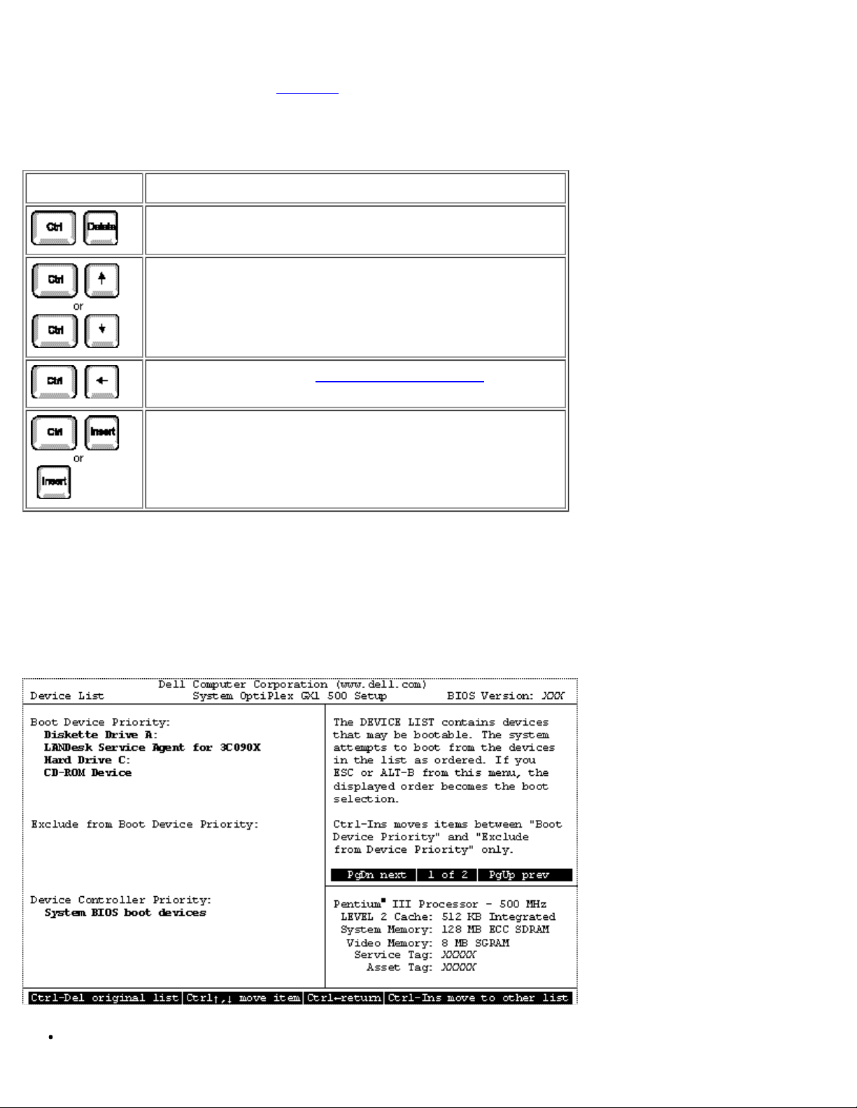
System Setup Options: Dell OptiPlex GX1 Small-Form-Factor System User's Guide
Device List provides access to the Device List screen where you can choose from a list of available boot
devices to boot from and specify the order in which your computer attempts to boot from these devices. To
view the Device List screen (see
navigation keys used on the Device List screen.
Figure 1), press <Ctrl> and the right-arrow key. Table 2 lists other
Table 2. Device-List Screen Navigation Keys
Keys Action
Returns the boot device lists to the default settings
Moves the selected item up or down in the boot
sequence
Exits to Page 2 of the System Setup screens
Moves the selected item from one Boot Device
Priority list to the other
NOTICE: Only a technically knowledgeable person should change the settings in the Device List
screen.
The Device List screen (see Figure 1) provides three options for listing and prioritizing the available boot
devices in your system.
Figure 1. Sample Device List Screen
Boot Device Priority
file:///C|/infodev/2013/eDoc/OpGX1/UG/setupopt.htm[2/21/2013 11:47:16 AM]
Page 75

System Setup Options: Dell OptiPlex GX1 Small-Form-Factor System User's Guide
The Boot Device Priority option lists all bootable devices (hard-disk drives, CD-ROM drives,
and so on) that are controlled by the system BIOS and any Plug and Play network adapters
installed in the computer.
Exclude From Boot Device Priority
The Exclude From Boot Device Priority option allows you to remove from the Boot Device
Priority option any boot devices that you want the system to ignore during system start-up.
Device Controller Priority
The Device Controller Priority option lists the system BIOS controller; any non-Plug and Play
devices, such as network adapter cards; and any secondary controller cards, such as a small
computer system interface (SCSI) adapter, installed in the computer.
NOTE: Non-Plug and Play devices appear in this list as Adapters without ID support.
When determining the order of devices to boot from, the system first considers the order of the devices listed
under the Device Controller Priority option, then the order of devices under Boot Device Priority.
To specify your priority preferences, order the devices under these options so that the highest-priority
controller is at the top of the Device Controller Priority option and the highest-priority device is at the top of
the Boot Device Priority option. Order the remainder of the devices in the Boot Device Priority option
according to your preferences. Move any devices that you want the system to ignore during system start-up
into the Exclude From Boot Device Priority option.
NOTE: The system defines drive C in the Boot Device Priority option as the first hard-disk drive
attached to the highest-priority device controller. Therefore, if you have a SCSI adapter installed in
your computer and you want the SCSI drive 0 to be drive C, you must move the SCSI adapter item to
the top of the Device Controller Priority option.
To change the order of the devices, press <Ctrl> and the up- or down-arrow key. If you want to revert to the
original Boot Device Priority option settings, press <Ctrl><Del>.
NOTE: If you exit the Device List option by pressing <Esc> or <Alt><b> without making any changes,
the Boot Sequence option is set to the Device List option.
Setup Password
Setup Password indicates whether a password is required before you can change option settings on the
System Setup screen. The settings for this option are normally Enabled or Not Enabled. A third setting,
Disabled By Jumper, displays if the Setup Password option is deactivated. (You can set a jumper on the
system board to deactivate the Setup Password option.)
If Setup Password is set to Enabled, you must enter the correct setup password before you can change the
settings for the majority of the System Setup options. If you do not enter the correct password in three tries,
the system lets you view, but not change, the settings on the System Setup screen, with one exception: if
Password Status is Unlocked, you may change the system password.
file:///C|/infodev/2013/eDoc/OpGX1/UG/setupopt.htm[2/21/2013 11:47:16 AM]
Page 76

System Setup Options: Dell OptiPlex GX1 Small-Form-Factor System User's Guide
NOTE: See "Using the Setup Password Feature" for instructions on assigning a setup password and
using or changing an existing setup password. See "Disabling a Forgotten Password" for instructions
on disabling a forgotten setup password.
Auto Power On
Auto Power On allows you to set the time and days of the week to turn on the computer system
automatically. You can set Auto Power On to turn on the system either every day or every Monday through
Friday.
NOTE: This feature does not work if you turn off your system using a power strip or surge protector.
Time is kept in a 24-hour format (hours:minutes). To change the start-up time, press the right-arrow key to
increase the number in the highlighted field or press the left-arrow key to decrease the number. If you prefer,
you can type numbers in both fields.
The default for Auto Power On is Disabled. For more information, see the System Utilities on the Dell
ResourceCD.
Power Management
This section explains the following topics:
Saving Monitor Power
Saving EIDE Hard-Disk Drive Power
For certain types of monitors and most EIDE hard-disk drives, you can reduce system power consumption by
enabling the power management feature. With Power Management enabled, these monitors and drives
automatically switch into low-power mode during periods of system inactivity.
Power Management can be implemented at three levels—Maximum, Regular, and Minimum. (The
different levels apply to the monitor only; hard-disk drive operation is the same for all three.) The default for
this option is Disabled.
Saving Monitor Power
If you have a Video Electronics Standards Association (VESA®) Display Power Management Signaling
(DPMS)-compliant monitor, enabling the Power Management option reduces monitor power consumption
during periods of keyboard and mouse inactivity
NOTICE: Check your monitor documentation to make sure you have a DPMS-compliant monitor
before you enable this feature. Otherwise, you risk damaging the monitor.
NOTE: The power management feature monitors activity of a mouse connected to the Personal
System/2 (PS/2)-compatible mouse port.
By setting Power Management to Maximum, Regular, or Minimum, you can set predefined time-out
file:///C|/infodev/2013/eDoc/OpGX1/UG/setupopt.htm[2/21/2013 11:47:16 AM]
Page 77

System Setup Options: Dell OptiPlex GX1 Small-Form-Factor System User's Guide
periods (see Table 3) for the two successive monitor shutdown stages, standby and off.
NOTE: Each monitor manufacturer defines the details of the shutdown stages for its own monitors.
But in all cases, power consumption decreases with each stage from "on" (full power) to "standby"
(reduced power; the display image usually disappears) to "off" (where power consumption is minimal).
To define these stages for your monitor, see the documentation that came with the monitor.
From either shutdown stage, you can return full power to the monitor in one of the following ways:
For most DPMS-compliant monitors, any subsequent activity—including moving the mouse—should
return full power to the monitor.
A few DPMS-compliant monitors require that you turn monitor power off and then on again to return to
full power.
Check your monitor documentation for information on how your monitor is designed to operate.
Saving EIDE Hard-Disk Drive Power
For most systems, enabling Power Management at any level causes EIDE hard-disk drives to switch to lowpower mode after about 20 minutes of system inactivity (see
Table 3).
NOTES: All EIDE drives shipped with your system support this feature. (For more information, see
"
ENERGY STAR® Compliance.")
However, not all EIDE hard-disk drives support this feature. Enabling this feature for drives that do not
support it may cause the EIDE drive to become inoperable until the computer is restarted and the
Power Management option is disabled.
In low-power mode, the disks inside the drive stop spinning. They remain idle until the next drive access,
which causes them to start spinning again. (Because the disks take a few seconds to regain full speed, you
may notice a slight delay when you next access the hard-disk drive.)
When Power Management is set to Disabled (the default), the disks spin constantly as long as the system
is turned on.
Table 3. Power Time-Out Periods
EIDE Drive
Power
Management Setting
Spindown
Time-Outs
Monitor Standby
Time-Outs
Monitor Off
Time-Outs
Disabled Never Never Never
Maximum 20 minutes 10 minutes 1 hour
Regular 20 minutes 20 minutes 1 hour
Minimum 20 minutes 1 hour Never
file:///C|/infodev/2013/eDoc/OpGX1/UG/setupopt.htm[2/21/2013 11:47:16 AM]
Page 78

System Setup Options: Dell OptiPlex GX1 Small-Form-Factor System User's Guide
Wakeup On LAN
Parallel Port configures the system’s built-in parallel port. This option can be set to 378h (the default), to
Wakeup On LAN determines whether the Wakeup On LAN feature is set to On or Off. You must reboot
your system before a change takes effect.
Sound
Sound determines whether the integrated audio controller is On or Off. You must reboot your system before
a change takes effect.
NIC
NIC determines whether an integrated network interface controller (NIC) is On or Off. You must reboot your
system before a change takes effect.
Mouse
Mouse enables or disables the system’s built-in PS/2-compatible mouse port. Disabling the mouse allows
an expansion card to use IRQ 12.
Serial Port 1 and Serial Port 2
Serial Port 1 and Serial Port 2 configure the system’s built-in serial ports. These options can be set to Auto
(the default) to automatically configure a port, to a particular designation (COM1 or COM3 for Serial Port 1;
COM2 or COM4 for Serial Port 2), or to Off to disable the port.
If you set a serial port to Auto and add an expansion card containing a port configured to the same
designation, the system automatically remaps the built-in port to the next available port designation that
shares the same IRQ setting as follows:
COM1 (input/output [I/O] address 3F8h), which shares IRQ4 with COM3, is remapped to COM3 (I/O
address 3E8h).
Likewise, COM2 (I/O address 2F8h), which shares IRQ3 with COM4, is remapped to COM4 (I/O
address 2E8h).
NOTES: When two COM ports share an IRQ setting, you can use either port as necessary, but you
may not be able to use them both at the same time. If the second port (COM3 or COM4) is also in
use, the built-in port is turned off.
If you are using the Microsoft® Windows® 95 or IBM® OS/2® operating system, you cannot use both
serial ports at the same time.
Parallel Port
file:///C|/infodev/2013/eDoc/OpGX1/UG/setupopt.htm[2/21/2013 11:47:16 AM]
Page 79

System Setup Options: Dell OptiPlex GX1 Small-Form-Factor System User's Guide
alternate addresses 278h or 3BCh, or to Off to disable the port.
Speaker
Off
NOTE: Do not set Parallel Port to 278h if you have an Enhanced Capabilities Port (ECP) device
connected to the port.
Parallel Mode
Parallel Mode controls whether the system’s built-in parallel port acts as an AT-compatible (unidirectional)
or PS/2-compatible (bidirectional) port.
Your system also supports ECP mode, which can be used by Windows 95 and Windows 98. Windows 95 and
Windows 98 use ECP protocol automatically if the operating system detects an ECP-capable device,
eliminating the need for an ECP setting in this option.
Set this option according to the type of peripheral device connected to the parallel port. To determine the
correct mode to use, see the documentation that came with the device.
IDE Hard Disk
IDE Hard Disk enables or disables the system’s built-in EIDE hard-disk drive interface.
With Auto (the default option) selected, the system turns off the built-in EIDE interface when necessary to
accommodate a controller card installed in an expansion slot.
As part of the boot routine, the system first checks for a primary hard-disk drive controller card installed in an
expansion slot. If no card is found, the system enables the built-in EIDE interface to use IRQ14 and IRQ15.
If a primary controller is detected on the expansion bus, the built-in EIDE interface is disabled.
Selecting Off disables the built-in EIDE interface.
Diskette
Diskette controls the operation of the system’s built-in diskette drive controller.
With Auto (the default) selected, the system turns off the built-in diskette drive controller when necessary to
accommodate a controller card installed in an expansion slot.
With Write Protect selected, nothing can be written to diskette drives and tape drives using the system’s
built-in diskette drive controller. (The system can still read from the drives.) When this option is selected, the
Auto option (whereby the system turns off the built-in diskette drive controller as necessary) is also in effect.
Selecting Off turns off the built-in diskette/tape drive controller; this option is used primarily for
troubleshooting purposes.
Speaker
determines whether the on-board speaker is On (the default) or
file:///C|/infodev/2013/eDoc/OpGX1/UG/setupopt.htm[2/21/2013 11:47:16 AM]
. A change to this option takes
Page 80

System Setup Options: Dell OptiPlex GX1 Small-Form-Factor System User's Guide
effect immediately (rebooting the system is not required).
System Data Options
The following options, which are not selectable, display information about the system. The microprocessor
type is also listed in the System Data box.
Level 2 Cache displays the size of the integrated cache (512 kilobytes [KB]).
System Memory indicates the entire amount of installed memory detected in your system, except for
memory on Expanded Memory Specification (EMS) expansion cards. After adding memory, check this
option to confirm that the new memory is installed correctly and is recognized by the system.
Video Memory displays the amount of video memory detected in your system.
Service Tag displays the system’s five-character service tag number, which was programmed into
nonvolatile random-access memory (NVRAM) by Dell during the manufacturing process. Refer to this
number during technical assistance or service calls. The service tag number is also accessed by
certain Dell support software, including the diagnostics software.
Asset Tag displays the customer-programmable asset tag number for the system if an asset tag
number has been assigned. You can use the Asset Tag utility, which is included with your system
utilities, to enter an asset tag number up to ten characters long into NVRAM. For information on using
the utility, see the Dell ResourceCD User's Guide.
Using the System Password Feature
NOTICE: The password features provide a basic level of security for the data on your system.
However, they are not foolproof. If your data requires more security, it is your responsibility to obtain
and use additional forms of protection, such as data encryption programs.
Your Dell system is shipped to you without the system password feature enabled. If system security is a
concern, you should operate your system only with system password protection.
You can assign a system password, as described in "
System Setup program. After a system password is assigned, only those who know the password have full
use of the system.
When the System Password option is set to Enabled, the computer system prompts you for the system
password just after the system boots.
Assigning a System Password," whenever you use the
To change an existing system password, you must know the password (see "Deleting or Changing an
Existing System Password"). If you assign and later forget a system password, you need to be able to
remove the computer cover to change a jumper setting that disables the system password feature (see
"
Disabling a Forgotten Password"). Note that you erase the setup password at the same time.
Assigning a System Password
NOTICE: If you leave your system running and unattended without having a system password
assigned, or if you leave your computer unlocked so that someone can disable the password by
file:///C|/infodev/2013/eDoc/OpGX1/UG/setupopt.htm[2/21/2013 11:47:16 AM]
Page 81

System Setup Options: Dell OptiPlex GX1 Small-Form-Factor System User's Guide
changing a jumper setting, anyone can access the data stored on your hard-disk drive.
Before you can assign a system password, you must enter the System Setup program and check the
System Password option.
When a system password is assigned, the option shown in the System Password option is Enabled. When
the system password feature is disabled by a jumper setting on the system board, the option shown is
Disabled by Jumper. You cannot change or enter a new system password if either of these options is
displayed.
When no system password is assigned and the password jumper on the system board is in the enabled
position (its default), the option shown for the System Password option is Not Enabled. Only when this
option is set to Not Enabled can you assign a system password, using the following procedure:
1. Verify that the
Password Status option is set to Unlocked.
2. Highlight the System Password option, and then press the left- or right-arrow key.
The option heading changes to Enter Password, followed by an empty seven-character field in
square brackets.
3. Type your new system password.
You can use up to seven characters in your password.
As you press each character key (or the spacebar for a blank space), a placeholder appears in
the field.
The password assignment operation recognizes keys by their location on the keyboard, without
distinguishing between lowercase and uppercase characters. For example, if you have an M in
your password, the system recognizes either M or m as correct.
Certain key combinations are not valid. If you enter one of these combinations, the speaker emits
a beep.
To erase a character when entering your password, press the <Backspace> key or the left-arrow
key.
NOTE: To escape from the field without assigning a system password, press the <Tab>
key or the <Shift><Tab> key combination to move to another field, or press the <Esc> key
at any time prior to completing step 5.
4. Press <Enter>.
If the new system password is less than seven characters, the whole field fills with placeholders.
Then the option heading changes to Verify Password, followed by another empty sevencharacter field in square brackets.
5. To confirm your password, type it a second time and press <Enter>.
The password setting changes to Enabled. Your system password is now set; you can exit the
System Setup program and begin using your system. Note, however, that password protection
does not take effect until you reboot the system by pressing the reset button or by turning the
file:///C|/infodev/2013/eDoc/OpGX1/UG/setupopt.htm[2/21/2013 11:47:16 AM]
Page 82

System Setup Options: Dell OptiPlex GX1 Small-Form-Factor System User's Guide
system off and then on again.
Using Your System Password to Secure Your System
Whenever you turn on your system, press the reset button, or reboot the system by pressing the
<Ctrl><Alt><Del> key combination, the following prompt appears on the screen when the Password Status
option is set to Unlocked:
Type in the password and...
— press <ENTER> to leave password security enabled.
— press <CTRL><ENTER> to disable password security.
Enter password:
If the Password Status option is set to Locked, the following prompt appears:
Type the password and press <Enter>.
After you type the correct system password and press <Enter>, your system boots and you can use the
keyboard and/or mouse to operate your system as usual.
NOTE: If you have assigned a setup password (see "Using the Setup Password Feature") the system
accepts your setup password as an alternate system password.
If a wrong or incomplete system password is entered, the following message appears on the screen:
** Incorrect password. **
Enter password:
If an incorrect or incomplete system password is entered again, the same message appears on the screen.
The third and subsequent times an incorrect or incomplete system password is entered, the system displays
the following message:
** Incorrect password. **
Number of unsuccessful password attempts: 3
System halted! Must power down.
The number of unsuccessful attempts made to enter the correct system password can alert you to an
unauthorized person attempting to use your system.
Even after your system is turned off and on, the previous message is displayed each time an incorrect or
incomplete system password is entered.
NOTE: You can use the Password Status option in conjunction with System Password and Setup
Password to further protect your system from unauthorized changes.
Deleting or Changing an Existing System Password
To delete or change an existing system password, perform the following steps:
1. Press the <F2> key to enter the System Setup program, and verify that the Password Status option is
file:///C|/infodev/2013/eDoc/OpGX1/UG/setupopt.htm[2/21/2013 11:47:16 AM]
Page 83

System Setup Options: Dell OptiPlex GX1 Small-Form-Factor System User's Guide
set to Unlocked.
Press the <Alt><p> key combination to move to Page 2 of the System Setup screens.
2. Reboot your system to force it to prompt you for a system password.
3. When prompted, type the system password.
4. Press the <Ctrl><Enter> key combination to disable the existing system password, instead of pressing
<Enter> to continue with the normal operation of your system.
5. Confirm that Not Enabled is displayed for the System Password option of the System Setup program.
If Not Enabled appears in the System Password option, the system password has been deleted.
If you want to assign a new password, continue to step 6. If Not Enabled is not displayed for the
System Password option, press the <Alt><p> key combination to reboot the system, and then
repeat steps 3 through 5.
6. To assign a new password, follow the procedure in "
Assigning a System Password."
Using the Setup Password Feature
Your Dell system is shipped to you without the setup password feature enabled. If system security is a
concern, you should operate your system with setup password protection.
You can assign a setup password whenever you use the System Setup program. After a setup password is
assigned, only those who know the password have full use of the System Setup program.
To change an existing password, you must know the setup password. If you assign and later forget a setup
password, you need to remove the computer cover to change a jumper setting that
password feature. Note that you erase the system password at the same time.
Assigning a Setup Password
A setup password can be assigned (or changed) only when the Setup Password option is set to Not
Enabled. To assign a setup password, perform the following steps:
1. Enter the System Setup program and go to Page 2 of the System Setup screens.
disables the setup
2. Highlight the Setup Password option and press the left- or right-arrow key.
The system prompts you to enter and verify the password. If a character is illegal for password
use, the system emits a beep.
NOTES: The setup password can be the same as the system password.
If the two passwords are different, the setup password can be used as an alternate system
password. However, the system password cannot be used in place of the setup password.
3. Enter and verify the password and click OK.
file:///C|/infodev/2013/eDoc/OpGX1/UG/setupopt.htm[2/21/2013 11:47:16 AM]
Page 84

System Setup Options: Dell OptiPlex GX1 Small-Form-Factor System User's Guide
After you verify the password, the Setup Password setting changes to Enabled. The next time
you enter the System Setup program, the system will prompt you for the setup password.
A change to the Setup Password option becomes effective immediately (rebooting the system is
not required).
Operating With a Setup Password Enabled
If Setup Password is set to Enabled, you must enter the correct setup password before you can modify the
majority of the System Setup options.
When you start the
System Setup program, Page 2 of the System Setup screens appears with the Setup
Password option highlighted, prompting you to type the password.
If you do not enter the correct password in three tries, the system lets you view, but not modify, the System
Setup screens—with the following exceptions:
If System Password is not enabled and is not locked via the Password Status option, you can
assign a system password (however, you cannot disable or change an existing system
password).
NOTE: You can use the Password Status option in conjunction with Setup Password to
protect the system password from unauthorized changes.
Deleting or Changing an Existing Setup Password
To delete or change an existing setup password, perform the following steps:
1. Enter the System Setup program and go to Page 2 of the System Setup screens.
2. Highlight the
Setup Password option, type in the setup password, and press the left- or right-arrow
key to delete the existing setup password.
The setting changes to Not Enabled.
3. If you want to assign a new setup password, follow the procedure in "
Assigning a Setup Password."
Disabling a Forgotten Password
If you forget your system or setup password, you cannot operate your system or change settings in the
System Setup program until you remove the computer cover, change the password jumper setting to disable
the passwords, and erase the existing passwords.
To disable a forgotten password, perform the following steps.
CAUTION: To avoid the possibility of electric shock, turn off the computer and any peripherals,
disconnect them from electrical outlets, and then wait at least 5 seconds before you remove
the computer cover. Also, before removing the computer cover, see the other precautions in
"
Safety First—For You and Your Computer."
file:///C|/infodev/2013/eDoc/OpGX1/UG/setupopt.htm[2/21/2013 11:47:16 AM]
Page 85

System Setup Options: Dell OptiPlex GX1 Small-Form-Factor System User's Guide
1. Remove the computer cover.
NOTICE: Verify that the AC power cable is removed before changing any jumper settings.
2. Remove the
Figure 4 in "Inside Your Computer" for the location of the password jumper (labeled "PSWD")
See
jumper plug from the PSWD jumper to disable the password feature.
on the system board.
3. Replace the computer cover.
4. Reconnect your computer and peripherals to their electrical outlets, and then turn them on.
Booting your system with the PSWD jumper plug removed erases the existing password(s).
5. Enter the
System Setup program and verify that the password is disabled. Proceed to step 6 if you
want to assign a new password.
NOTE: Before you assign a new system and/or setup password, you must replace the
PSWD jumper plug.
6. Remove the computer cover.
7. Replace the PSWD jumper plug.
8. Replace the computer cover, and then reconnect the computer and peripherals to their electrical
outlets and turn them on.
Booting with the PSWD jumper installed reenables the password feature. When you enter the
System Setup program, both password options appear as Not Enabled, meaning that the
password feature is enabled but that no password has been assigned.
9.
Assign a new system password and/or setup password.
Responding to Error Messages
If an error message appears on your monitor screen while the system is booting, make note of the message.
Then, before entering the System Setup program, refer to "
message and suggestions for correcting any errors. However, it is normal to receive an error message the
first time you boot the system after a memory upgrade. In that case, refer to the instructions in "
Memory."
If you are given an option to press either <F1> to continue or <F2> to run the System Setup program, press
the <F2> key.
Messages and Codes" for an explanation of the
System
Back to Contents Page
file:///C|/infodev/2013/eDoc/OpGX1/UG/setupopt.htm[2/21/2013 11:47:16 AM]
Page 86
Internal Components: Dell OptiPlex GX1 Small-Form-Factor System User's Guide
Back to Contents Page
Internal Components: Dell™ OptiPlex™ GX1 Small-Form-Factor
System User's Guide
Overview Troubleshooting Expansion Cards
Safety First — For You and Your Computer Troubleshooting System Memory
Removing and Replacing the Computer Cover Troubleshooting the Video Subsystem
Troubleshooting a Wet Computer Troubleshooting the System Board
Troubleshooting a Damaged Computer Troubleshooting Drives
Troubleshooting the Battery
Overview
This section provides troubleshooting procedures for components inside your computer. Before you start any
of the procedures in this section, do the following:
Perform the procedures described in "Checking Connections and Switches" and "System Setup
Program."
Read the safety instructions in "Safety First—For You and Your Computer."
You need the following items to perform the procedures in this section:
A copy of the Dell ResourceCD
A small flat-blade screwdriver and a #1 Phillips-head screwdriver (or quarter-inch hex-nut driver)
Safety First—For You and Your Computer
The procedures in this section require that you remove the cover and work inside your computer. While
working inside your computer, do not attempt to service the computer except as explained in this guide and
elsewhere in Dell documentation. Always follow the instructions closely.
Working inside your computer is safe—if you observe the following precautions.
CAUTION: FOR YOUR PERSONAL SAFETY AND PROTECTION OF THE EQUIPMENT
Before you start to work on the computer, perform the following steps in the sequence indicated:
1. Turn off the computer and all peripherals.
file:///C|/infodev/2013/eDoc/OpGX1/UG/internal.htm[2/21/2013 11:47:17 AM]
Page 87

Internal Components: Dell OptiPlex GX1 Small-Form-Factor System User's Guide
2. Touch an unpainted metal surface on the computer chassis, such as the metal around the card-slot
openings at the back of your computer, before touching anything inside your computer.
3. Disconnect the computer and peripherals from their electrical outlets. Doing so reduces the potential for
personal injury or shock. Also disconnect any telephone or telecommunication lines from the computer.
While you work, periodically touch an unpainted metal surface on the computer chassis to dissipate
any static electricity that might harm internal components.
In addition, Dell recommends that you periodically review the safety instructions in your System Information
Guide.
Removing and Replacing the Computer Cover
NOTE: If your small-form-factor chassis has an optional stand for vertical orientation attached to it,
remove the optional stand
before you remove the computer cover.
To remove the computer cover, perform the following steps:
1. Turn off your computer and peripherals, and observe the caution for your personal safety and
protection of the equipment described in "Safety First—For You and Your Computer
."
2. If you have installed a padlock through the padlock ring on the back panel, remove the padlock.
3. Remove the computer cover as follows:
a. Press in on the two securing buttons until the cover is free to swing up (see Figure 1).
b. Raise the back of the cover, and pivot it toward the front of the computer.
c. Lift the cover off the hooks at the front of the chassis.
Figure 1. Removing the Small-Form-Factor Computer Cover
1 Securing buttons (2)
file:///C|/infodev/2013/eDoc/OpGX1/UG/internal.htm[2/21/2013 11:47:17 AM]
Page 88

Internal Components: Dell OptiPlex GX1 Small-Form-Factor System User's Guide
Front of Computer
To replace the computer cover, perform the following steps:
1. Check all cable connections, especially those that might have come loose during your work. Fold
cables out of the way so that they do not catch on the computer cover. Make sure cables are not
routed over the drive cage—they will prevent the cover from closing properly.
2. Check to see that no tools or extra parts (including screws) are left inside the computer's chassis.
3. Replace the computer cover as follows:
a. Face the front of the computer and hold the cover at a slight angle as shown in Figure 2
b. Align the bottom of the cover with the bottom of the chassis, and insert the three hooks on the
cover into the three recessed slots on the computer chassis so that the tabs catch the hooks
inside the slots.
NOTE: The three hooks on the cover are located in the front at the bottom. The three
recessed slots on the computer chassis are located in the front at the bottom (see Figure
2).
.
c. Pivot the cover down toward the back of the chassis and into position. Press down on the back
corners of the cover until the securing buttons click into place.
Figure 2. Replacing the Small-Form-Factor Computer Cover
file:///C|/infodev/2013/eDoc/OpGX1/UG/internal.htm[2/21/2013 11:47:17 AM]
1 Securing buttons (2)
2 Hooks (3)
3 Recessed slots (3)
Page 89
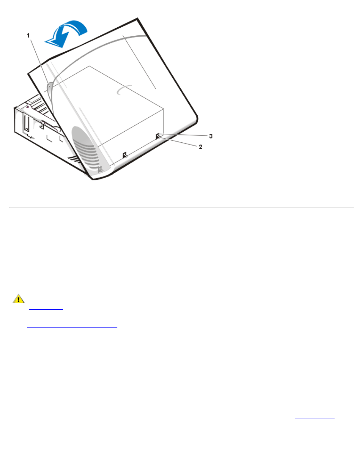
Internal Components: Dell OptiPlex GX1 Small-Form-Factor System User's Guide
Front of Computer
4. If you are using a padlock to secure your system, reinstall the padlock.
Troubleshooting a Wet Computer
Liquids can damage your computer. While you are not likely to submerge your computer, spills, splashes,
and excessive humidity can also cause damage. If an external device (such as a printer or an external drive)
gets wet, contact the manufacturer for instructions. If your computer gets wet, perform the following steps:
1. Turn off the system, including any attached peripherals, and disconnect all the AC power cables from
their electrical outlets. Also, disconnect any telephone or telecommunication lines from the computer.
CAUTION: Before you remove the computer cover, see "Safety First—For You and Your
Computer."
2. Remove the computer cover
3. Let the computer dry for at least 24 hours.
Make sure that it is thoroughly dry before proceeding.
.
4. Remove all expansion cards installed in the computer except a drive controller card and video
expansion card.
5. Replace the computer cover, reconnect the system to an electrical outlet, and turn it on.
If the system has power, proceed to step 6. If the system does not have power, see "Getting Help
instructions on obtaining technical assistance.
6. Turn off the system, disconnect it from the electrical outlet, remove the computer cover, and reinstall all
file:///C|/infodev/2013/eDoc/OpGX1/UG/internal.htm[2/21/2013 11:47:17 AM]
" for
Page 90

Internal Components: Dell OptiPlex GX1 Small-Form-Factor System User's Guide
expansion cards you removed in step 4.
7. Replace the computer cover, and reconnect the system to an electrical outlet. Also, reconnect any
telephone or telecommunication lines to the computer.
8. Insert the Dell ResourceCD into the appropriate drive, reboot the system, and run the System Set Test
Group in the Dell Diagnostics.
If the tests complete successfully, your system is operating properly. If any of the tests fail, see "Getting
Help" for instructions on obtaining technical assistance.
Troubleshooting a Damaged Computer
If your computer was dropped or damaged, you should check your computer to see if it functions properly. If
an external device attached to your computer is dropped or damaged, contact the manufacturer of the device
for instructions or see "Getting Help
troubleshoot a damaged computer, perform the following steps:
" for information on obtaining technical assistance from Dell. To
1. Turn off the system, including any attached peripherals, and disconnect all the AC power cables from
their electrical outlets. Also, disconnect any telephone or telecommunication lines from the computer.
CAUTION: Before you remove the computer cover, see "Safety First—For You and Your
Computer."
2. Remove the computer cover
.
3. Check all the expansion-card connections in the computer.
4. Verify the diskette/tape drive, hard-disk drive, and all other internal connections.
Make sure that all cables are properly connected and that all components are properly seated in their
connectors and sockets.
5. Replace the computer cover
, reconnect the system to an electrical outlet, and reconnect any telephone
or telecommunication lines.
6. Insert the Dell ResourceCD into the appropriate drive, reboot the system, and run the System Set Test
Group in the Dell Diagnostics.
If the tests complete successfully, your system is operating properly. If any of the tests fail, see "Getting
Help" for instructions on obtaining technical assistance.
Troubleshooting the Battery
CAUTION: There is a danger of a new battery exploding if it is incorrectly installed. Replace the
battery only with the same or equivalent type recommended by the manufacturer. Discard used
batteries according to the manufacturer's instructions.
file:///C|/infodev/2013/eDoc/OpGX1/UG/internal.htm[2/21/2013 11:47:17 AM]
Page 91

Internal Components: Dell OptiPlex GX1 Small-Form-Factor System User's Guide
If an error message indicates a problem with the battery or if the System Setup program loses the system
Group in the Dell Diagnostics.
configuration information when the computer is turned off, the battery may be defective.
To troubleshoot the battery, perform the following steps:
1. Turn off the system, including any attached peripherals, and disconnect all the AC power cables from
their electrical outlets. Also, disconnect any telephone or telecommunication lines from the computer.
CAUTION: Before you remove the computer cover, see "Safety First—For You and Your
Computer."
2. Remove the computer cover
.
3. Reseat the battery in its socket.
The battery is a coin cell that snaps into a socket on the system board.
4. If the problem is not resolved, replace the battery.
If the problem is still not resolved, you may have a faulty system board. See "Getting Help
" for
instructions on obtaining technical assistance.
Troubleshooting Expansion Cards
If an error message indicates an expansion-card problem or if an expansion card seems to perform
incorrectly or not at all, the problem could be a faulty connection, a conflict with software or other hardware,
or a faulty expansion card. To troubleshoot expansion cards, perform the following steps:
1. Turn off the system, including any attached peripherals, and disconnect all the AC power cables from
their electrical outlets. Also, disconnect any telephone or telecommunication lines from the computer.
CAUTION: Before you remove the computer cover, see "Safety First—For You and Your
Computer."
2. Remove the computer cover
.
3. Verify that each expansion card is firmly seated in its connector. If any expansion cards are loose,
reseat them.
4. Verify that any cables are firmly connected to their corresponding connectors on the expansion cards. If
any cables appear loose, reconnect them.
For instructions on which cables should be attached to specific connectors on an expansion card, see
the expansion card's documentation.
5. Remove all expansion cards
except the video card.
6. Replace the computer cover, reconnect the system to an electrical outlet, and turn it on.
7. Insert the Dell ResourceCD into the appropriate drive, reboot the system, and run the RAM Test
file:///C|/infodev/2013/eDoc/OpGX1/UG/internal.htm[2/21/2013 11:47:17 AM]
Page 92

Internal Components: Dell OptiPlex GX1 Small-Form-Factor System User's Guide
If the tests complete successfully, proceed to step 8. If any of the tests fail, see "Getting Help" for
instructions on obtaining technical assistance.
8. Turn off the system, disconnect it from the electrical outlet, and remove the computer cover.
9. Reinstall one of the expansion cards you removed previously, and repeat steps 6 and 7.
If any of the tests fail, the expansion card you just reinstalled is faulty and needs to be replaced. If the
tests complete successfully, repeat steps 8 and 9 with another expansion card.
10. If you have replaced all the expansion cards removed previously and the expansion card problem is not
resolved, see "Getting Help
" for information on obtaining technical assistance.
Troubleshooting System Memory
A computer memory problem can be a faulty dual in-line memory module (DIMM) or a faulty system board. If
a random-access memory (RAM) error message appears, the computer probably has a memory problem.
When you turn on or reboot the system, the Caps Lock and Scroll Lock indicators on the keyboard should
flash momentarily and then turn off. If the Num Lock
option in the System Setup program is set to On, the
Num Lock indicator should flash momentarily and then remain on; otherwise, it should turn off. Abnormal
operation of these indicators can result from a defective DIMM in socket A. Follow these steps to
troubleshoot system memory:
1. Turn on the system, including any attached peripherals.
CAUTION: Before you remove the computer cover, see "Safety First—For You and Your
Computer."
2. If an error message indicates invalid system configuration information, enter the System Setup program
and check the System Memory option.
If the amount of memory displayed does not match the amount of memory installed, turn off the
computer, disconnect it from the electrical outlet, remove the computer cover
, and reseat the DIMMs in
their sockets.
3. Replace the computer cover, reconnect the system to an electrical outlet, and turn it on.
4. If the problem is not resolved, insert the Dell ResourceCD into the appropriate drive, reboot the system,
and run the RAM
Test Group in the Dell Diagnostics.
If the Dell Diagnostics identifies a faulty DIMM, replace that DIMM
. If the Dell Diagnostics determines
that the system board is faulty or if the Dell Diagnostics does not identify the cause of the problem and
the problem is still not resolved, see "Getting Help
" for instructions on obtaining technical assistance.
Troubleshooting the Video Subsystem
Troubleshooting video problems involves determining which of the following is the source of the problem: the
file:///C|/infodev/2013/eDoc/OpGX1/UG/internal.htm[2/21/2013 11:47:17 AM]
Page 93

Internal Components: Dell OptiPlex GX1 Small-Form-Factor System User's Guide
monitor, the monitor interface cable, or the integrated video subsystem.
Before attempting to troubleshoot the video subsystem, perform the procedure found in "Troubleshooting the
Monitor" to determine whether or not the monitor is the source of the problem.
If the monitor is not at fault, perform the following steps:
1. Check the monitor cable connections
.
2. If the problem is not resolved, insert the Dell ResourceCD into the appropriate drive, reboot the system,
and run the Video Test Group
in the Dell Diagnostics.
If any of the tests fail, see "Getting Help" for instructions on obtaining technical assistance.
Troubleshooting the System Board
A system board problem can result from a defective system board component, a faulty power supply, or a
defective component connected to the system board. If an error message indicates a system board problem,
perform the following steps:
1. Insert the Dell ResourceCD into the appropriate drive, reboot the system, and run the System Set Test
Group in the Dell Diagnostics.
If any of the tests fail, see "Getting Help" for instructions on obtaining technical assistance.
2. Turn off the system, including any attached peripherals, and disconnect all the AC power cables from
their electrical outlets. Also, disconnect any telephone or telecommunication lines from the computer.
CAUTION: Before you remove the computer cover, see "Safety First—For You and Your
Computer."
3. Remove the computer cover
.
4. Verify that the power cables from the power supply are firmly connected to the connectors on the
system board.
5. Replace the computer cover, reconnect the system to an electrical outlet, and turn it on. If the problem
is not resolved, proceed to step 6.
6. Perform the procedure in "Troubleshooting Expansion Cards
."
7. Perform the procedure in "Troubleshooting the Keyboard."
8. If the problem is still not resolved, see "Getting Help" for instructions on obtaining technical assistance.
Troubleshooting Drives
If the monitor displays a system error message to indicate a drive problem during execution of either the boot
routine or the Dell Diagnostics
, or if a drive is not operating correctly, perform the following steps:
file:///C|/infodev/2013/eDoc/OpGX1/UG/internal.htm[2/21/2013 11:47:17 AM]
Page 94

Internal Components: Dell OptiPlex GX1 Small-Form-Factor System User's Guide
1. Enter the System Setup program, and verify that the problem drive is configured correctly. Make any
necessary changes, and reboot the system.
2. If the problem is not resolved, turn off the system, including any attached peripherals, and disconnect
all the AC power cables from their electrical outlets. Also, disconnect any telephone or
telecommunication lines from the computer.
CAUTION: Before you remove the computer cover, see "Safety First—For You and Your
Computer."
3. Remove the computer cover
.
4. Verify that the power cables from the electrical outlet are firmly connected to the connectors on each
drive. Also verify that the interface cable for each drive is firmly connected to the drive and to the
system board.
5. Replace the computer cover
, reconnect the system to an electrical outlet, and turn it on.
If the problem is not resolved, proceed to step 6.
6. Insert the Dell ResourceCD into the appropriate drive, reboot the system, and run the appropriate test
group in the Dell Diagnostics
.
If the Dell Diagnostics identifies a faulty drive, replace the drive. If the Dell Diagnostics identifies a
faulty controller, the system board may be faulty. See "Getting Help
" for instructions on obtaining
technical assistance.
Back to Contents Page
file:///C|/infodev/2013/eDoc/OpGX1/UG/internal.htm[2/21/2013 11:47:17 AM]
Page 95

External Components: Dell GX1 Small-Form-Factor System User's Guide
Back to Contents Page
External Components: Dell™ OptiPlex™ GX1 Small-Form-Factor
System User's Guide
Overview Troubleshooting I/O Ports
Troubleshooting the Monitor Troubleshooting Basic I/O Functions
Troubleshooting the Keyboard Troubleshooting a Parallel Printer
Troubleshooting the Mouse Troubleshooting a Serial I/O Device
Overview
This section provides troubleshooting procedures for equipment that connects directly to the input/output
(I/O) panel of your computer, such as your monitor, keyboard, mouse, or printer. Before performing any of
the procedures in this section, see "Checking Connections and Switches
procedures for the equipment that is malfunctioning.
You need a copy of the Dell ResourceCD to perform the procedures in this section.
." Then perform the troubleshooting
Troubleshooting the Monitor
Troubleshooting video problems involves determining which of the following is the source of the problem:
Monitor or monitor interface cable
Video controller
The procedures in this section troubleshoot problems with the monitor and the monitor interface cable only.
If information on the monitor screen is displayed incorrectly or not at all, perform each of the following steps
in the order indicated until the problem is resolved:
1. Turn on the system, including any attached peripherals.
2. Adjust the switches and controls as specified in the monitor's documentation to correct the video
image, including the horizontal and vertical position and size.
3. Insert the Dell ResourceCD into the appropriate drive, reboot the system, and run the Video Test
Group in the Dell Diagnostics.
4. Turn off the system and disconnect it from the electrical outlet. Swap the monitor with one of the same
type that is working, and reconnect the system to an electrical outlet.
5. Reboot the system, and run the Video Test Group again.
file:///C|/infodev/2013/eDoc/OpGX1/UG/external.htm[2/21/2013 11:47:18 AM]
Page 96

External Components: Dell GX1 Small-Form-Factor System User's Guide
If the tests complete successfully, the original monitor was faulty. If the tests still fail, the video
controller on the system board may be faulty. See "Getting Help
assistance.
" for instructions on obtaining technical
Troubleshooting the Keyboard
This procedure determines what kind of keyboard problem you have. If a system error message indicates a
keyboard problem when you start the computer system or if the keyboard does not operate as expected,
perform the following steps in the order indicated until the problem is resolved:
1. If the keyboard or its cable shows signs of physical damage or if the keys do not work, replace the
keyboard with a working keyboard.
2. Insert the Dell ResourceCD into the appropriate drive, reboot the system, and run the Keyboard
Group in the Dell Diagnostics.
If the Keyboard Interactive Test
If the Keyboard Controller Test fails, the system board may be faulty. See "Getting Help" for
instructions on obtaining technical assistance.
fails, replace the keyboard.
Test
Troubleshooting the Mouse
This procedure determines what kind of mouse problem you have. If a system error message indicates a
mouse problem when you start the computer system or if the mouse does not operate as expected, perform
the following steps in the order indicated until the problem is resolved:
1. Clean the mouse as instructed in your mouse documentation.
Most mice have a ball that can be removed and cleaned of debris by turning the mouse upside down
and removing a cover on the bottom of the mouse. Also remove any lint or other debris that has
accumulated on the bottom of the mouse.
2. If the mouse or its cable shows signs of physical damage or if the buttons do not work, replace the
mouse with a working mouse.
3. Insert the Dell ResourceCD into the appropriate drive, reboot the system, and run the Mouse Test
the Dell Diagnostics
If the Mouse Test fails, the system board may be faulty. See "Getting Help
technical assistance.
.
" for instructions on obtaining
Troubleshooting I/O Ports
This section provides a procedure for troubleshooting the ports on your computer's I/O panel and the
equipment connected to them, such as a printer, scanner, or other peripheral device.
You can also use this procedure to test I/O ports on expansion cards. However, you should first complete the
file:///C|/infodev/2013/eDoc/OpGX1/UG/external.htm[2/21/2013 11:47:18 AM]
in
Page 97

External Components: Dell GX1 Small-Form-Factor System User's Guide
procedures in "Troubleshooting Expansion Cards" to verify that the card is configured and installed correctly.
If a system error message indicates a port problem or if equipment connected to a port seems to perform
incorrectly or not at all, the source of the problem may be any of the following:
A faulty connection between the I/O port and the peripheral device
A faulty cable between the I/O port and the peripheral device
A faulty peripheral device
Incorrect settings in the System Setup program
Incorrect settings in the system's configuration files
Faulty I/O port logic on the system board
NOTE: With certain modems installed, the Serial/Infrared Port Test Group subtests may fail
because the modem appears to the diagnostics as a serial port, but it cannot be tested as a serial
port. If you have a modem installed and you experience a serial port test failure, remove the modem
and run the diagnostic tests again.
Troubleshooting Basic I/O Functions
If a system error message indicates an I/O port problem or the device connected to the port does not function
properly, follow these steps in the order indicated until the problem is resolved:
1. Enter the System Setup program and verify that the settings for the Serial Port 1, Serial Port 2, and
Parallel Port options are set to Auto.
2. Insert the Dell ResourceCD into the appropriate drive, reboot the system, and run the Serial/Infrared
Ports Test Group and/or the Parallel Ports Test Group in the Dell Diagnostics.
If any of the tests fail, the system board may be faulty. See " Getting Help" for instructions on obtaining
technical assistance.
If the problem persists, go to " Troubleshooting a Parallel Printer
" or " Troubleshooting a Serial I/O
Device," depending on which device appears to be malfunctioning.
Troubleshooting a Parallel Printer
If the information in " Troubleshooting Basic I/O Functions" indicates that the problem is with a parallel
printer, perform the following steps in the order indicated until the problem is resolved:
1. Reinstall the printer device driver.
See the documentation for the printer and for your operating system for instructions on reinstalling the
printer driver.
2. Turn off the parallel printer and computer, replace the parallel printer interface cable with a known
file:///C|/infodev/2013/eDoc/OpGX1/UG/external.htm[2/21/2013 11:47:18 AM]
Page 98

External Components: Dell GX1 Small-Form-Factor System User's Guide
working cable, and turn on the parallel printer and computer.
If the problem is resolved, the original printer cable was faulty.
3. Run the parallel printer's self-test.
If the test fails, the printer is faulty.
If the problem still is not resolved, the system board may be faulty. See " Getting Help
" for
instructions on obtaining technical assistance.
Troubleshooting a Serial I/O Device
If the information in " Troubleshooting Basic I/O Functions" indicates that the problem is with a device
connected to one of the serial ports, perform the following steps in the order indicated until the problem is
resolved:
1. Attach the serial device to the other serial port (for example, if it is currently connected to serial port 1,
attach the device to serial port 2).
If the problem is resolved, the serial port on the system board is faulty. See " Getting Help
instructions on obtaining technical assistance.
2. If the faulty device has a detachable serial cable, replace the serial cable.
If the problem is resolved, the serial cable was faulty.
3. Replace the faulty serial device.
" for
If the problem is still not resolved, the system board may be faulty. See " Getting Help
on obtaining technical assistance.
Back to Contents Page
" for instructions
file:///C|/infodev/2013/eDoc/OpGX1/UG/external.htm[2/21/2013 11:47:18 AM]
Page 99

Getting Help: Dell OptiPlex GX1 Small-Form-Factor System User's Guide
Back to Contents Page
Getting Help: Dell™ OptiPlex™ GX1 Small-Form-Factor System
User's Guide
Help Overview Contacting Dell
Back to Contents Page
file:///C|/infodev/2013/eDoc/OpGX1/UG/getting.htm[2/21/2013 11:47:19 AM]
Page 100
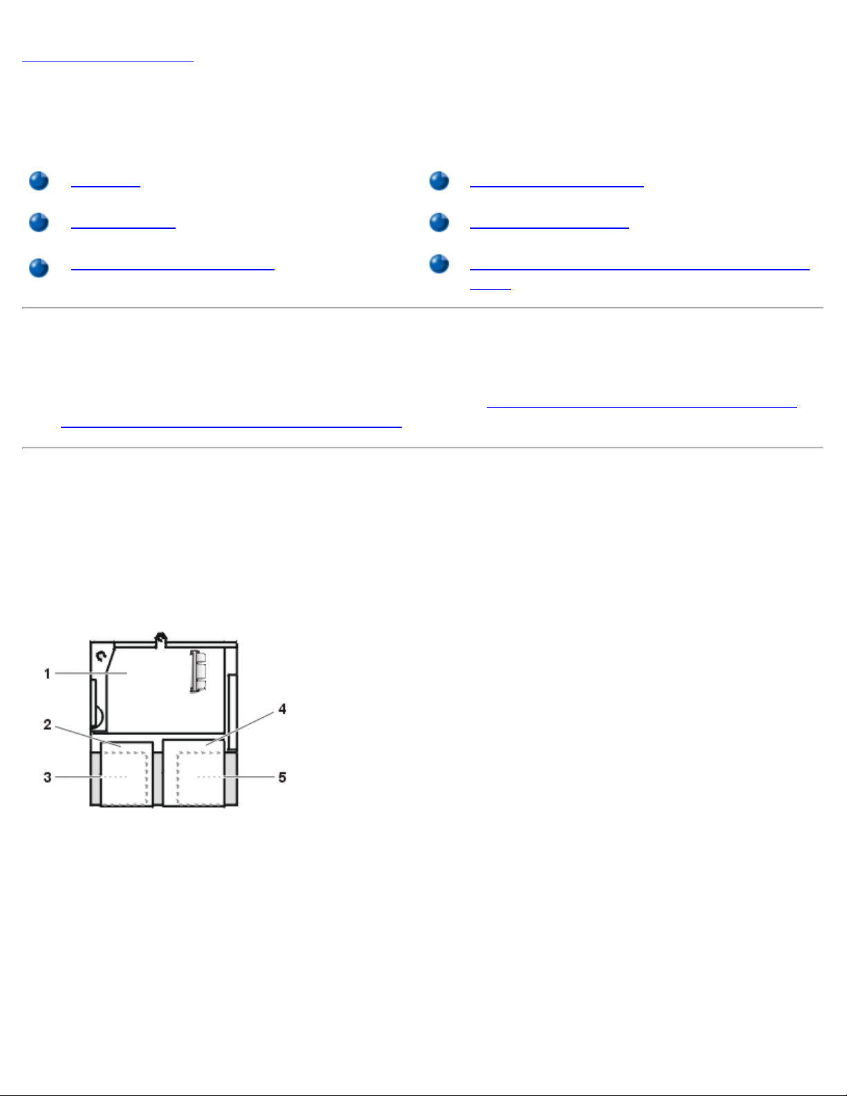
Inside Your Computer: Dell OptiPlex GX1 Small-Form-Factor System User's Guide
Back to Contents Page
Inside Your Computer: Dell™ OptiPlex™ GX1 Small-Form-Factor
System User's Guide
Overview System Board Jumpers
Internal Views System Board Labels
System Board Components Removing and Replacing the Expansion-Card
Cage
Overview
This section describes the inside of your computer and may be used as a reference before performing an
upgrade procedure. Before removing the computer cover, see "Safety First—For You and Your Computer
and "Removing and Replacing the Computer Cover
."
"
Internal Views
Figure 1 shows a side view of the small-form-factor chassis to help you orient yourself when working inside
the computer.
Figure 1. Small-Form-Factor Chassis Orientation View
1 System board
2 Diskette drive
3 Hard-disk drive
4 CD-ROM drive
5 Power supply
Figure 2 shows the small-form-factor chassis with the cover removed.
Figure 2. Inside the Small-Form-Factor Chassis
file:///C|/infodev/2013/eDoc/OpGX1/UG/inside.htm[2/21/2013 11:47:19 AM]
1 CD-ROM drive interface cable
2 Externally accessible upper bay
3 Hard-disk drive
 Loading...