

Dell OptiPlex Gn Service Manual
'HOO2SWL3OH[*QDQG*Q6\VWHPV
6(59,&(0$18$/
®


'HOO2SWL3OH[*QDQG*Q6\VWHPV
6(59,&(0$18$/
®

Information in this manual is subject to change without notice.
1997 Dell Computer Corporation. All rights reserved.
Reproduction in any m an ner whatsoever without the written permission of Dell Comput er Corporation is strictly forb idden.
Trademarks used in this text: Dell, the DELL logo, and OptiPlex are registered trademarks of Dell Computer Corporation; Intel and Pentium are registered trad emarks
and MMX is a trademark of Intel Corporation; Microsoft, MS-DOS , and Windows are registered trademarks of Microsoft Corporation; IBM is a registered trademark
of International Busi ness Machines Corporation; 3Com is a registered trademark of 3Com Corporation.
Other trademarks and tr ade names may be used in this docum ent to refer to either the ent itie s cla i mi ng the marks and names or their prod uc ts. D el l Co mputer
Corporation disclai m s a ny proprietary interest in trad emarks and trade names other th an its own.
October 1997 P/N 56023 Rev. A01

Contents
Chapter 1
System Overview. . . . . . . . . . . . . . . . . . . . . . . . . . . . . . . 1-1
System Features . . . . . . . . . . . . . . . . . . . . . . . . . . . . . . . . . . . . . . . . . . . . . . . 1-2
Advanced Expansion Subsystem . . . . . . . . . . . . . . . . . . . . . . . . . . . . . . . 1-7
Low-Profile Computer’s Expansion-Card Slots. . . . . . . . . . . . . . . . . 1-8
Midsize Computer’s Expansion-Card Slots . . . . . . . . . . . . . . . . . . . . 1-8
Mini Tower Computer’s Expansion-Card Slots . . . . . . . . . . . . . . . . . 1-9
Hard-Disk Drive Options . . . . . . . . . . . . . . . . . . . . . . . . . . . . . . . . . . . . 1-10
Low-Profile Computers . . . . . . . . . . . . . . . . . . . . . . . . . . . . . . . . . . 1-11
Midsize Computers. . . . . . . . . . . . . . . . . . . . . . . . . . . . . . . . . . . . . . 1-11
Mini Tower Computers. . . . . . . . . . . . . . . . . . . . . . . . . . . . . . . . . . . 1-11
Enhanced Dual-Interface EIDE Subsystem . . . . . . . . . . . . . . . . . . . . . . 1-11
Built-In Video Controller . . . . . . . . . . . . . . . . . . . . . . . . . . . . . . . . . . . . 1-11
Optional NIC. . . . . . . . . . . . . . . . . . . . . . . . . . . . . . . . . . . . . . . . . . . . . . 1-12
Floor Stand . . . . . . . . . . . . . . . . . . . . . . . . . . . . . . . . . . . . . . . . . . . . . . . 1-12
Computer Service . . . . . . . . . . . . . . . . . . . . . . . . . . . . . . . . . . . . . . . . . . . . . 1-13
Computer Power Supply. . . . . . . . . . . . . . . . . . . . . . . . . . . . . . . . . . . . . 1-13
Pin Assignments for the DC Power Connectors. . . . . . . . . . . . . . . . 1-14
DC Power Distribution . . . . . . . . . . . . . . . . . . . . . . . . . . . . . . . . . . . 1-15
System Board . . . . . . . . . . . . . . . . . . . . . . . . . . . . . . . . . . . . . . . . . . . . . 1-20
Main Memory . . . . . . . . . . . . . . . . . . . . . . . . . . . . . . . . . . . . . . . . . . 1-21
System Board Jumpers . . . . . . . . . . . . . . . . . . . . . . . . . . . . . . . . . . . 1-21
Interrupt Assignments. . . . . . . . . . . . . . . . . . . . . . . . . . . . . . . . . . . . . . . . . . 1-23
DMA Channel Assignments. . . . . . . . . . . . . . . . . . . . . . . . . . . . . . . . . . . . . 1-24
Technical Specifications. . . . . . . . . . . . . . . . . . . . . . . . . . . . . . . . . . . . . . . . 1-25
v

Chapter 2
Basic Troubleshooting . . . . . . . . . . . . . . . . . . . . . . . . . . 2-1
Initial User Contact . . . . . . . . . . . . . . . . . . . . . . . . . . . . . . . . . . . . . . . . . . . . 2-1
External Visual Inspection . . . . . . . . . . . . . . . . . . . . . . . . . . . . . . . . . . . . . . . 2-2
Observing the Boot Routine. . . . . . . . . . . . . . . . . . . . . . . . . . . . . . . . . . . . . . 2-3
Internal Visual Inspection . . . . . . . . . . . . . . . . . . . . . . . . . . . . . . . . . . . . . . . 2-4
Eliminating Resource Conflicts . . . . . . . . . . . . . . . . . . . . . . . . . . . . . . . . . . . 2-5
Running the Dell Diagnostics. . . . . . . . . . . . . . . . . . . . . . . . . . . . . . . . . . . . . 2-6
Getting Help. . . . . . . . . . . . . . . . . . . . . . . . . . . . . . . . . . . . . . . . . . . . . . . . . . 2-6
Chapter 3
Beep Codes and Error Messages . . . . . . . . . . . . . . . . . . 3-1
POST Beep Codes . . . . . . . . . . . . . . . . . . . . . . . . . . . . . . . . . . . . . . . . . . . . . 3-1
System Error Messages . . . . . . . . . . . . . . . . . . . . . . . . . . . . . . . . . . . . . . . . . 3-4
Chapter 4
Removing and Replacing Parts on the
Low-Profile Chassis. . . . . . . . . . . . . . . . . . . . . . . . . . . . . 4-1
Recommended Tools . . . . . . . . . . . . . . . . . . . . . . . . . . . . . . . . . . . . . . . . . . . 4-1
Precautionary Measures . . . . . . . . . . . . . . . . . . . . . . . . . . . . . . . . . . . . . . . . . 4-2
Floor Stand. . . . . . . . . . . . . . . . . . . . . . . . . . . . . . . . . . . . . . . . . . . . . . . . . . . 4-3
Computer Cover. . . . . . . . . . . . . . . . . . . . . . . . . . . . . . . . . . . . . . . . . . . . . . . 4-4
Eject, Power, and Reset Buttons . . . . . . . . . . . . . . . . . . . . . . . . . . . . . . . . . . 4-5
Front-Panel Inserts . . . . . . . . . . . . . . . . . . . . . . . . . . . . . . . . . . . . . . . . . . . . . 4-6
Control Panel . . . . . . . . . . . . . . . . . . . . . . . . . . . . . . . . . . . . . . . . . . . . . . . . . 4-8
Drives . . . . . . . . . . . . . . . . . . . . . . . . . . . . . . . . . . . . . . . . . . . . . . . . . . . . . . . 4-9
3.5-Inch Diskette Drive Assembly. . . . . . . . . . . . . . . . . . . . . . . . . . . . . 4-10
5.25-Inch Drive Assembly . . . . . . . . . . . . . . . . . . . . . . . . . . . . . . . . . . . 4-11
Hard-Disk Drive Assembly . . . . . . . . . . . . . . . . . . . . . . . . . . . . . . . . . . 4-12
System Power Supply. . . . . . . . . . . . . . . . . . . . . . . . . . . . . . . . . . . . . . . . . . 4-13
System Board Components . . . . . . . . . . . . . . . . . . . . . . . . . . . . . . . . . . . . . 4-14
Expansion Cards. . . . . . . . . . . . . . . . . . . . . . . . . . . . . . . . . . . . . . . . . . . 4-15
Expansion-Card Cage. . . . . . . . . . . . . . . . . . . . . . . . . . . . . . . . . . . . 4-15
Expansion Card . . . . . . . . . . . . . . . . . . . . . . . . . . . . . . . . . . . . . . . . 4-16
DIMMs. . . . . . . . . . . . . . . . . . . . . . . . . . . . . . . . . . . . . . . . . . . . . . . . . . 4-18
Microprocessor/Heat Sink Assembly. . . . . . . . . . . . . . . . . . . . . . . . . . . 4-19
System Battery . . . . . . . . . . . . . . . . . . . . . . . . . . . . . . . . . . . . . . . . . . . . 4-21
System Board . . . . . . . . . . . . . . . . . . . . . . . . . . . . . . . . . . . . . . . . . . . . . . . . 4-22
vi
Riser Board. . . . . . . . . . . . . . . . . . . . . . . . . . . . . . . . . . . . . . . . . . . . 4-17

Chapter 5
Removing and Replacing Parts
on the Midsize Chassis. . . . . . . . . . . . . . . . . . . . . . . . . . 5-1
Recommended Tools . . . . . . . . . . . . . . . . . . . . . . . . . . . . . . . . . . . . . . . . . . . 5-1
Precautionary Measures . . . . . . . . . . . . . . . . . . . . . . . . . . . . . . . . . . . . . . . . . 5-2
Floor Stand . . . . . . . . . . . . . . . . . . . . . . . . . . . . . . . . . . . . . . . . . . . . . . . . . . . 5-3
Computer Cover . . . . . . . . . . . . . . . . . . . . . . . . . . . . . . . . . . . . . . . . . . . . . . . 5-4
Eject, Power, and Reset Buttons. . . . . . . . . . . . . . . . . . . . . . . . . . . . . . . . . . . 5-5
Front-Panel Inserts . . . . . . . . . . . . . . . . . . . . . . . . . . . . . . . . . . . . . . . . . . . . . 5-6
Control Panel . . . . . . . . . . . . . . . . . . . . . . . . . . . . . . . . . . . . . . . . . . . . . . . . . 5-8
Drives . . . . . . . . . . . . . . . . . . . . . . . . . . . . . . . . . . . . . . . . . . . . . . . . . . . . . . . 5-9
3.5-Inch Drive Assembly . . . . . . . . . . . . . . . . . . . . . . . . . . . . . . . . . . . . 5-10
5.25-Inch Drive Assembly . . . . . . . . . . . . . . . . . . . . . . . . . . . . . . . . . . . 5-11
Hard-Disk Drive Bracket . . . . . . . . . . . . . . . . . . . . . . . . . . . . . . . . . . . . 5-12
Hard-Disk Drive . . . . . . . . . . . . . . . . . . . . . . . . . . . . . . . . . . . . . . . . . . . 5-13
System Power Supply. . . . . . . . . . . . . . . . . . . . . . . . . . . . . . . . . . . . . . . . . . 5-14
System Board Components. . . . . . . . . . . . . . . . . . . . . . . . . . . . . . . . . . . . . . 5-15
Expansion Cards . . . . . . . . . . . . . . . . . . . . . . . . . . . . . . . . . . . . . . . . . . . 5-16
Expansion-Card Cage . . . . . . . . . . . . . . . . . . . . . . . . . . . . . . . . . . . . 5-16
Expansion Card. . . . . . . . . . . . . . . . . . . . . . . . . . . . . . . . . . . . . . . . . 5-17
Riser Board . . . . . . . . . . . . . . . . . . . . . . . . . . . . . . . . . . . . . . . . . . . . 5-18
DIMMs . . . . . . . . . . . . . . . . . . . . . . . . . . . . . . . . . . . . . . . . . . . . . . . . . . 5-19
Microprocessor/Heat Sink Assembly . . . . . . . . . . . . . . . . . . . . . . . . . . . 5-20
System Battery . . . . . . . . . . . . . . . . . . . . . . . . . . . . . . . . . . . . . . . . . . . . 5-22
System Board . . . . . . . . . . . . . . . . . . . . . . . . . . . . . . . . . . . . . . . . . . . . . . . . 5-23
Chapter 6
Removing and Replacing Parts
on the Mini Tower Chassis. . . . . . . . . . . . . . . . . . . . . . . 6-1
Recommended Tools . . . . . . . . . . . . . . . . . . . . . . . . . . . . . . . . . . . . . . . . . . . 6-1
Precautionary Measures . . . . . . . . . . . . . . . . . . . . . . . . . . . . . . . . . . . . . . . . . 6-2
Computer Cover . . . . . . . . . . . . . . . . . . . . . . . . . . . . . . . . . . . . . . . . . . . . . . . 6-3
Front Bezel . . . . . . . . . . . . . . . . . . . . . . . . . . . . . . . . . . . . . . . . . . . . . . . . . . . 6-4
Eject, Power, and Reset Buttons. . . . . . . . . . . . . . . . . . . . . . . . . . . . . . . . . . . 6-5
Front-Panel Inserts . . . . . . . . . . . . . . . . . . . . . . . . . . . . . . . . . . . . . . . . . . . . . 6-6
Control Panel . . . . . . . . . . . . . . . . . . . . . . . . . . . . . . . . . . . . . . . . . . . . . . . . . 6-8
vii

Drives . . . . . . . . . . . . . . . . . . . . . . . . . . . . . . . . . . . . . . . . . . . . . . . . . . . . . . . 6-9
3.5-Inch Drive Assembly . . . . . . . . . . . . . . . . . . . . . . . . . . . . . . . . . . . . 6-10
5.25-Inch Drive Assembly . . . . . . . . . . . . . . . . . . . . . . . . . . . . . . . . . . . 6-11
Hard-Disk Drive Bracket . . . . . . . . . . . . . . . . . . . . . . . . . . . . . . . . . . . . 6-13
Hard-Disk Drive. . . . . . . . . . . . . . . . . . . . . . . . . . . . . . . . . . . . . . . . . . . 6-14
System Power Supply. . . . . . . . . . . . . . . . . . . . . . . . . . . . . . . . . . . . . . . . . . 6-15
System Board Components . . . . . . . . . . . . . . . . . . . . . . . . . . . . . . . . . . . . . 6-16
Expansion Cards. . . . . . . . . . . . . . . . . . . . . . . . . . . . . . . . . . . . . . . . . . . 6-17
Expansion-Card Cage. . . . . . . . . . . . . . . . . . . . . . . . . . . . . . . . . . . . 6-17
Expansion Card . . . . . . . . . . . . . . . . . . . . . . . . . . . . . . . . . . . . . . . . 6-18
Riser Board. . . . . . . . . . . . . . . . . . . . . . . . . . . . . . . . . . . . . . . . . . . . 6-19
DIMMs. . . . . . . . . . . . . . . . . . . . . . . . . . . . . . . . . . . . . . . . . . . . . . . . . . 6-20
Microprocessor/Heat Sink Assembly. . . . . . . . . . . . . . . . . . . . . . . . . . . 6-21
System Battery . . . . . . . . . . . . . . . . . . . . . . . . . . . . . . . . . . . . . . . . . . . . 6-23
System Board . . . . . . . . . . . . . . . . . . . . . . . . . . . . . . . . . . . . . . . . . . . . . . . . 6-24
Appendix A
System Setup Program . . . . . . . . . . . . . . . . . . . . . . . . . .A-1
System Setup Screens. . . . . . . . . . . . . . . . . . . . . . . . . . . . . . . . . . . . . . . . . . .A-2
Index
Figures
Figure 1-1. Computer Orientation . . . . . . . . . . . . . . . . . . . . . . . . . . . . . . 1-3
Figure 1-2. Front-Panel Features . . . . . . . . . . . . . . . . . . . . . . . . . . . . . . . 1-4
Figure 1-3. Internal View of the Low-Profile Computer. . . . . . . . . . . . . 1-5
Figure 1-4. Internal View of the Midsize Computer . . . . . . . . . . . . . . . . 1-6
Figure 1-5. Internal View of the Mini Tower Computer . . . . . . . . . . . . . 1-7
Figure 1-6. Riser Board for the Low-Profile Computers. . . . . . . . . . . . . 1-8
Figure 1-7. EM Riser Board for the Low-Profile Computers . . . . . . . . . 1-8
Figure 1-8. Riser Board for the Midsize Computers . . . . . . . . . . . . . . . . 1-9
Figure 1-9. EM Riser Board for the Midsize Computers. . . . . . . . . . . . . 1-9
Figure 1-10. Riser Board for the Mini Tower Computers . . . . . . . . . . . . 1-10
Figure 1-11. EM Riser Board for the Mini Tower Computers . . . . . . . . 1-10
Figure 1-12. NIC Connector on I/O Panel. . . . . . . . . . . . . . . . . . . . . . . . 1-12
Figure 1-13. DC Power Connector P1 . . . . . . . . . . . . . . . . . . . . . . . . . . . 1-14
Figure 1-14. DC Power Connectors P2 (Midsize and Mini Tower),
viii
P3, P4, P5, P6, and P9. . . . . . . . . . . . . . . . . . . . . . . . . . . . . 1-14

Figure 1-15. DC Power Connectors P2 (Low-Profile) and P7. . . . . . . . . 1-15
Figure 1-16. DC Power Cables for the Low-Profile Computers . . . . . . . 1-15
Figure 1-17. DC Power Distribution for the Low-Profile Computers . . . 1-16
Figure 1-18. DC Power Cables for the Midsize
and Mini Tower Computers. . . . . . . . . . . . . . . . . . . . . . . . . 1-17
Figure 1-19. DC Power Distribution for the Midsize Computers . . . . . . 1-18
Figure 1-20. DC Power Distribution for the Mini Tower Computers . . . 1-19
Figure 1-21. System Board Components . . . . . . . . . . . . . . . . . . . . . . . . . 1-20
Figure 1-22. System Board Jumpers. . . . . . . . . . . . . . . . . . . . . . . . . . . . . 1-21
Figure 4-1. Optional Floor Stand Removal . . . . . . . . . . . . . . . . . . . . . . . 4-3
Figure 4-2. Computer Cover Removal . . . . . . . . . . . . . . . . . . . . . . . . . . . 4-4
Figure 4-3. Padlock. . . . . . . . . . . . . . . . . . . . . . . . . . . . . . . . . . . . . . . . . . 4-4
Figure 4-4. Eject, Power, and Reset Button Removal . . . . . . . . . . . . . . . 4-5
Figure 4-5. 5.25-Inch Front-Panel Insert Removal. . . . . . . . . . . . . . . . . . 4-6
Figure 4-6. 3.5-Inch Front-Panel Insert Removal. . . . . . . . . . . . . . . . . . . 4-7
Figure 4-7. Control Panel Removal . . . . . . . . . . . . . . . . . . . . . . . . . . . . . 4-8
Figure 4-8. Drive Hardware . . . . . . . . . . . . . . . . . . . . . . . . . . . . . . . . . . . 4-9
Figure 4-9. 3.5-Inch Diskette Drive Removal . . . . . . . . . . . . . . . . . . . . 4-10
Figure 4-10. 5.25-Inch Drive Assembly Removal . . . . . . . . . . . . . . . . . . 4-11
Figure 4-11. Hard-Disk Drive Assembly Removal . . . . . . . . . . . . . . . . . 4-12
Figure 4-12. System Power-Supply Removal . . . . . . . . . . . . . . . . . . . . . 4-13
Figure 4-13. System Board Components . . . . . . . . . . . . . . . . . . . . . . . . . 4-14
Figure 4-14. Expansion-Card Cage Removal. . . . . . . . . . . . . . . . . . . . . . 4-15
Figure 4-15. Expansion-Card Removal . . . . . . . . . . . . . . . . . . . . . . . . . . 4-16
Figure 4-16. Riser Board Removal. . . . . . . . . . . . . . . . . . . . . . . . . . . . . . 4-17
Figure 4-17. DIMM Removal. . . . . . . . . . . . . . . . . . . . . . . . . . . . . . . . . . 4-18
Figure 4-18. DIMM Installation. . . . . . . . . . . . . . . . . . . . . . . . . . . . . . . . 4-18
Figure 4-19. Microprocessor Securing-Clip Removal . . . . . . . . . . . . . . . 4-19
Figure 4-20. Microprocessor Removal. . . . . . . . . . . . . . . . . . . . . . . . . . . 4-20
Figure 4-21. System Battery Removal . . . . . . . . . . . . . . . . . . . . . . . . . . . 4-21
Figure 4-22. System Board Removal . . . . . . . . . . . . . . . . . . . . . . . . . . . . 4-22
Figure 5-1. Floor Stand Removal . . . . . . . . . . . . . . . . . . . . . . . . . . . . . . . 5-3
Figure 5-2. Computer Cover Removal . . . . . . . . . . . . . . . . . . . . . . . . . . . 5-4
Figure 5-3. Padlock. . . . . . . . . . . . . . . . . . . . . . . . . . . . . . . . . . . . . . . . . . 5-4
Figure 5-4. Eject, Power, and Reset Button Removal . . . . . . . . . . . . . . . 5-5
Figure 5-5. 5.25-Inch Front-Panel Insert Removal. . . . . . . . . . . . . . . . . . 5-6
Figure 5-6. 3.5-Inch Front-Panel Insert Removal. . . . . . . . . . . . . . . . . . . 5-7
Figure 5-7. Control Panel Removal . . . . . . . . . . . . . . . . . . . . . . . . . . . . . 5-8
Figure 5-8. Drive Hardware . . . . . . . . . . . . . . . . . . . . . . . . . . . . . . . . . . . 5-9
ix

Figure 5-9. 3.5-Inch Diskette Drive Removal . . . . . . . . . . . . . . . . . . . . 5-10
Figure 5-10. 5.25-Inch Drive Assembly Removal. . . . . . . . . . . . . . . . . . 5-11
Figure 5-11. 5.25-Inch Drive Removal . . . . . . . . . . . . . . . . . . . . . . . . . . 5-11
Figure 5-12. Hard-Disk Drive Bracket Removal. . . . . . . . . . . . . . . . . . . 5-12
Figure 5-13. Hard-Disk Drive Removal. . . . . . . . . . . . . . . . . . . . . . . . . . 5-13
Figure 5-14. System Power-Supply Removal . . . . . . . . . . . . . . . . . . . . . 5-14
Figure 5-15. System Board Components. . . . . . . . . . . . . . . . . . . . . . . . . 5-15
Figure 5-16. Expansion-Card Cage Removal . . . . . . . . . . . . . . . . . . . . . 5-16
Figure 5-17. Expansion-Card Removal . . . . . . . . . . . . . . . . . . . . . . . . . . 5-17
Figure 5-18. Riser Board Removal . . . . . . . . . . . . . . . . . . . . . . . . . . . . . 5-18
Figure 5-19. DIMM Removal . . . . . . . . . . . . . . . . . . . . . . . . . . . . . . . . . 5-19
Figure 5-20. DIMM Installation. . . . . . . . . . . . . . . . . . . . . . . . . . . . . . . . 5-19
Figure 5-21. Microprocessor Securing-Clip Removal. . . . . . . . . . . . . . . 5-20
Figure 5-22. Microprocessor Removal . . . . . . . . . . . . . . . . . . . . . . . . . . 5-21
Figure 5-23. System Battery Removal. . . . . . . . . . . . . . . . . . . . . . . . . . . 5-22
Figure 5-24. System Board Removal. . . . . . . . . . . . . . . . . . . . . . . . . . . . 5-23
Figure 6-1. Computer Cover Removal. . . . . . . . . . . . . . . . . . . . . . . . . . . 6-3
Figure 6-2. Padlock . . . . . . . . . . . . . . . . . . . . . . . . . . . . . . . . . . . . . . . . . 6-3
Figure 6-3. Front-Bezel Removal . . . . . . . . . . . . . . . . . . . . . . . . . . . . . . 6-4
Figure 6-4. Eject, Power, and Reset Button Removal . . . . . . . . . . . . . . . 6-5
Figure 6-5. 5.25-Inch Front-Panel Insert Removal . . . . . . . . . . . . . . . . . 6-6
Figure 6-6. 3.5-Inch Front-Panel Insert Removal . . . . . . . . . . . . . . . . . . 6-7
Figure 6-7. Control Panel Removal . . . . . . . . . . . . . . . . . . . . . . . . . . . . . 6-8
Figure 6-8. Drive Hardware. . . . . . . . . . . . . . . . . . . . . . . . . . . . . . . . . . . 6-9
Figure 6-9. 3.5-Inch Drive Assembly Removal. . . . . . . . . . . . . . . . . . . 6-10
Figure 6-10. 3.5-Inch Diskette Drive Removal . . . . . . . . . . . . . . . . . . . . 6-11
Figure 6-11. 5.25-Inch Drive Assembly Removal. . . . . . . . . . . . . . . . . . 6-11
Figure 6-12. 5.25-Inch Drive Removal . . . . . . . . . . . . . . . . . . . . . . . . . . 6-12
Figure 6-13. Hard-Disk Drive Bracket Removal. . . . . . . . . . . . . . . . . . . 6-13
Figure 6-14. Hard-Disk Drive Removal. . . . . . . . . . . . . . . . . . . . . . . . . . 6-14
Figure 6-15. System Power-Supply Removal . . . . . . . . . . . . . . . . . . . . . 6-15
Figure 6-16. System Board Components. . . . . . . . . . . . . . . . . . . . . . . . . 6-16
Figure 6-17. Expansion-Card Cage Removal . . . . . . . . . . . . . . . . . . . . . 6-17
Figure 6-18. Expansion-Card Removal . . . . . . . . . . . . . . . . . . . . . . . . . . 6-18
Figure 6-19. Riser Board Removal . . . . . . . . . . . . . . . . . . . . . . . . . . . . . 6-19
Figure 6-20. DIMM Removal . . . . . . . . . . . . . . . . . . . . . . . . . . . . . . . . . 6-20
Figure 6-21. DIMM Installation. . . . . . . . . . . . . . . . . . . . . . . . . . . . . . . . 6-20
Figure 6-22. Microprocessor Securing-Clip Removal. . . . . . . . . . . . . . . 6-21
x

Figure 6-23. Microprocessor Removal. . . . . . . . . . . . . . . . . . . . . . . . . . . 6-22
Figure 6-24. System Battery Removal . . . . . . . . . . . . . . . . . . . . . . . . . . . 6-23
Figure 6-25. System Board Removal . . . . . . . . . . . . . . . . . . . . . . . . . . . . 6-24
Figure A-1. System Setup Screens . . . . . . . . . . . . . . . . . . . . . . . . . . . . . .A-2
Figure A-2. Device List Screen. . . . . . . . . . . . . . . . . . . . . . . . . . . . . . . . .A-6
Tables
Table 1-1. DC Voltage Ranges. . . . . . . . . . . . . . . . . . . . . . . . . . . . . . . 1-13
Table 1-2. System-Board Jumper Descriptions . . . . . . . . . . . . . . . . . . 1-22
Table 1-3. Interrupt Assignments . . . . . . . . . . . . . . . . . . . . . . . . . . . . . 1-23
Table 1-4. DREQ Line Assignments . . . . . . . . . . . . . . . . . . . . . . . . . . 1-24
Table 1-5. Technical Specifications . . . . . . . . . . . . . . . . . . . . . . . . . . . 1-25
Table 3-1. POST Beep Codes. . . . . . . . . . . . . . . . . . . . . . . . . . . . . . . . . 3-2
Table 3-2. System Error Messages . . . . . . . . . . . . . . . . . . . . . . . . . . . . . 3-5
Table A-1. System Setup Categories. . . . . . . . . . . . . . . . . . . . . . . . . . . .A-3
xi

ead This First
R
A prerequisite for using this manual to service Dell computer systems is a
basic knowledge of IBM®-compatible PCs and prior training in
IBM-compatible PC troubleshooting techniques. In addition to information
provided in this manual and the Reference and Installation Guide that came
with the system, Dell provides the Diagnostics and Troubleshooting Guide
for troubleshooting procedures and instructions on using the Dell Diagnostics
to test the computer system.
arnings, Cautions, and Notes
W
Throughout this manual, there may be blocks of text printed in bold type or in
italic type. These blocks are warnings, cautions, and notes, and they are used as
follows:
WARNING: A WARNING indicates the potential for bodily harm and
provides instructions for how to avoid the problem.
CAUTION: A CAUTION indicates either potential damage to hardware
or loss of data and provides instructions for how to avoid the problem.
NOTE: A NOTE provides helpful information about using the computer system.
xii

Chapter 1
System Overview
he Dell
T
Enhanced Manageability (EM), are high-speed, upgradable, expandable computers. (The name Dell OptiPlex Gn and Gn+ will be used to refer to both
versions, unless otherwise indicated.) They are available in three sizes: a lowprofile desktop computer, a midsize desktop computer, and a mini tower
computer. Chapters 1 through 3 and Appendix A contain information that
applies to all models of the Dell OptiPlex Gn and Gn+ computers. Chapters 4, 5,
and 6 are chassis-specific.
The Dell OptiPlex Gn and Gn+ computers use the Intel® Pentium® microprocessor with MMX™ technology. These Dell computers incorporate the
high-performance PCI local bus as well as the ISA expansion bus. These buses
are built into the system board, which also integrates the microprocessor, memory controller, hard-disk drive controller , video controller, and other elements of
the basic computer.
The microprocessor for the OptiPlex Gn and Gn+ computers is installed in a
type 7 ZIF socket, which allows the computer to be upgraded when faster
microprocessors become available.
The Pentium microprocessor contains a built-in clock multiplier circuit, which
increases the internal operating frequency to a multiple of the system clock frequency, which is 66 MHz.
The microprocessors for each of these computers and their operating frequencies are as follows:
®
OptiPlex® Gn and Gn+, and the Dell OptiPlex Gn and Gn+ with
Dell OptiPlex Gn and Gn+ 166 computers — 166-MHz Pentium micropro-
•
cessor with MMX technology
Dell OptiPlex Gn and Gn+ 200 computers — 200-MHz Pentium micropro-
•
cessor with MMX technology
Dell OptiPlex Gn and Gn+ 233 computers — 233-MHz Pentium micropro-
•
cessor with MMX technology
System Overvi ew 1-1

S
ystem Features
In addition to the standard features found in a traditional personal computer , the
Dell OptiPlex Gn and Gn+ computers include the following new and/or
advanced features:
Advanced combination ISA and PCI expansion subsystem
•
Plug and Play ISA expansion-card capability
•
Enhanced dual-interface EIDE subsystem
•
Integrated cache memory controller that supports 512 KB of external
•
pipelined-burst cache memory
Main system memory consisting of 16 to 256 MB of high-speed EDO
•
DIMMs
Built-in SVGA controller attached to the PCI bus with 2 MB of video
•
memory
Optional integrated 10- or 100-Mbps Ethernet NIC
•
Optional NIC adapter providing Wakeup On LAN capability (available only
•
on the EM)
Integrated Universal Serial Bus (USB) controller with two USB-compliant
•
connectors
Self-Monitoring Analysis Reporting Technology (SMART)-compliant hard-
•
disk drives and SMART support in the system BIOS, which provides
notification at system start-up if a hard-disk drive has become unreliable
New quick-test feature in the Dell Diagnostics (for more information about
•
Quick Test, see “Running the Dell Diagnostics” in Chapter 2).
All of these features except the new quick-test feature and the SMART support
are briefly described in this chapter. For a complete list of system features, see
“Technical Specifications” found later in this chapter.
When following the text in this manual, assume that the location or direction
relative to the computer is as shown in Figure 1-1.
1-2
Dell OptiPlex Gn and Gn+ Systems Service Manual
back
back
left
side
front
low-profile computer
right
side
top
left
side
right
side
front
midsize computer
frontback
bottom
mini tower computer
Figure 1-1. Computer Orientation
System Overvi ew 1-3
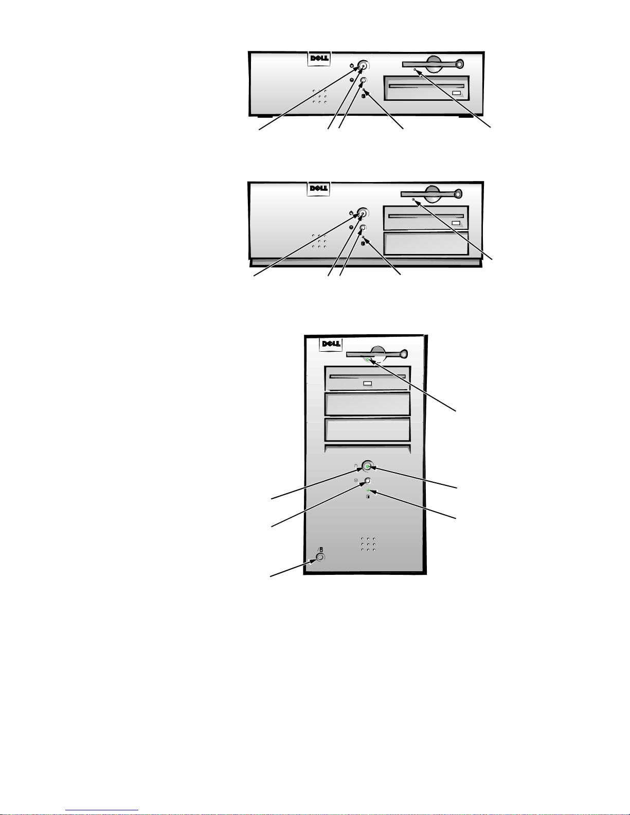
Figure 1-2. Front-Panel Features
diskette-drive
access indicator
reset button
hard-disk drive
access indicator
power button
power indicator
diskette-drive
access indicator
reset button
hard-disk drive
access indicator
power button
power indicator
midsize computer
low-profile computer
mi
ni tower computer
power indicator
hard-disk drive
access indicator
power button
reset button
diskette-drive
access indicator
cover release button
1-4
Dell OptiPlex Gn and Gn+ Systems Service Manual
CAUTION: To avoid possible data or file structure corruptions, the
front-panel reset button should be used only when the c omputer cannot
be rebooted by pressing <Ctrl><Alt><Del>. Before you use the reset
button to initiate a hardware reset, close any open application programs
and files if possible.
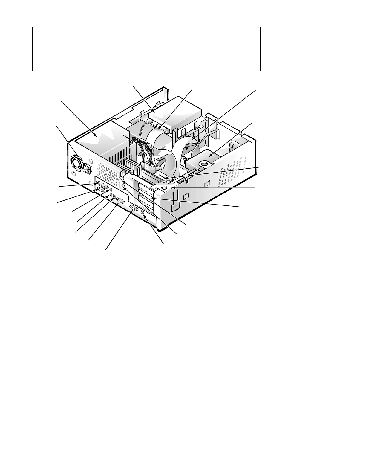
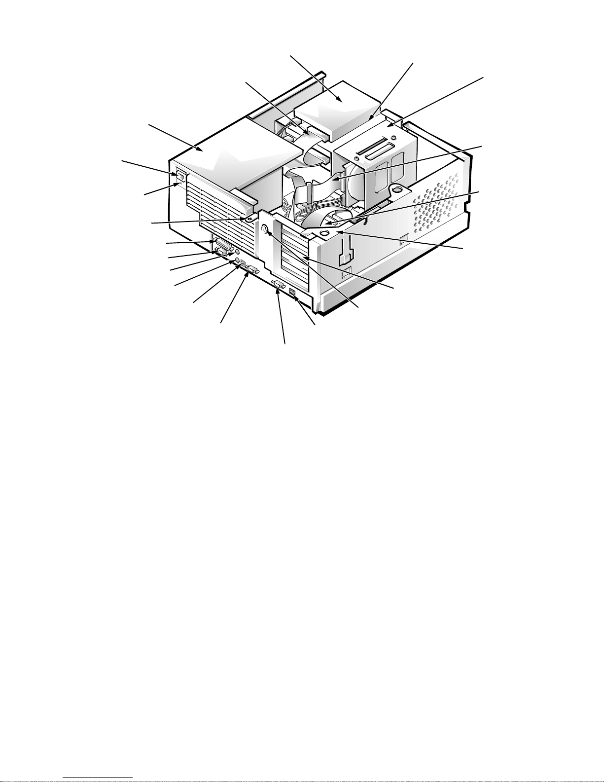
power supply
AC power
receptacle
voltage
selection
switch
parallel port
connector
serial port 1
connector
mouse connector
keyboard connector
USB connectors (2)
serial port 2 connector
video connector
3.5-inch diskette drive
diskette/tape drive
interface cable
padlock ring
security cable slot
optional system board
NIC connector (Gn+)
hard-disk drive
interface cable
hard-disk drive
system board
expansion-card
cage
expansion-card slots (3)
Figure 1-3. Internal View of the Low-Profile Computer
System Overvi ew 1-5
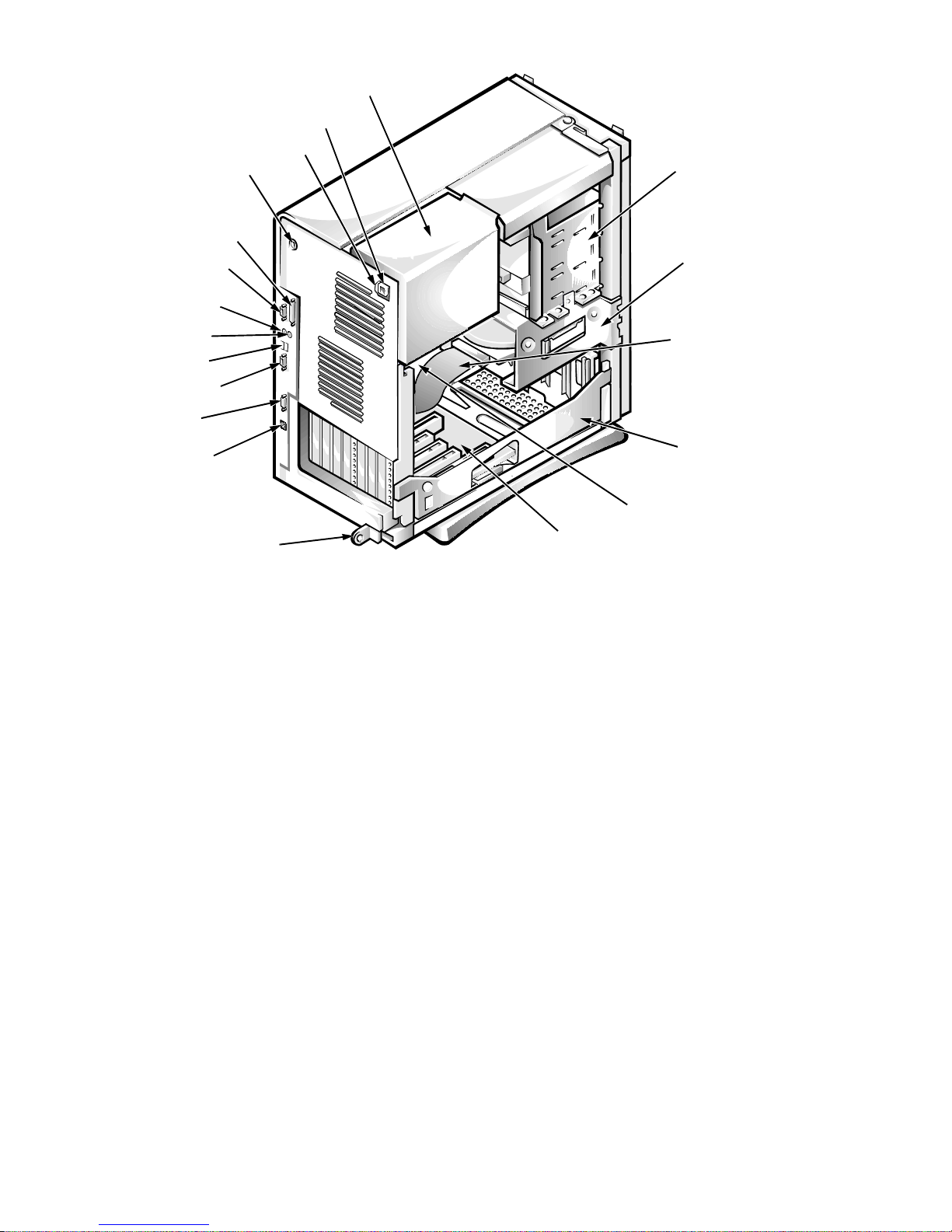
diskette/tape drive interface cable
power supply
3.5-inch diskette drive
drive cage
hard-disk drive
bracket
AC power
receptacle
voltage
selection switch
padlock ring
parallel port connector
serial port 1 connector
mouse connector
keyboard connector
USB connectors (2)
serial port 2 connector
hard-disk drive
interface cable
system board
expansion-card cage
expansion-card slots (5)
security cable slot
optional system board
NIC connector (Gn+)
video connector
Figure 1-4. Internal View of the Midsize Computer
1-6
Dell OptiPlex Gn and Gn+ Systems Service Manual
AC power receptacle
voltage selection switch
security cable slot
parallel port connector
serial port 1 connector
keyboard connector
power supply
internal drive bays
hard-disk drive
bracket
mouse connector
USB connectors (2)
serial port 2 connector
video connector
optional system board
NIC connector (Gn+)
system board
padlock ring
riser board
Figure 1-5. Internal View of the Mini Tower Computer
Advanced Expansion Subsystem
The Dell OptiPlex Gn and Gn+ computers offer advanced expansion subsystems that can support a mixture of traditional ISA expansion cards (called
legacy c ards), Plug and Play ISA expansion cards, and PCI expansion cards. The
operating system or the ISA Configuration Utility (ICU), included with the
computer, provides a means of avoiding resource conflicts that might arise from
such an arrangement.
hard-disk drive
interface cable
expansion-card cage
NOTE: For systems running the Microsoft® Windows® 95 operating system,
the functions provided by the ICU are handled by the Device Manager, which
can be accessed by double-clicking the System icon in the Control Panel.
W indows 95 documentation provides instructions on using the Device Manager
to manage resources and resolve conflicts.
After all legacy cards have been configured by the operating system or with the
ICU, the computer automatically assigns any required memory space, IRQ
lines, and DMA channels to any installed Plug and Play ISA expansion cards
and PCI expansion cards the next time the computer is rebooted. Chapter 3,
“Using the ISA Configuration Utility,” in the Refer ence and Installation Guide
describes the ICU and provides instructions for using it to configure the
computer.
System Overvi ew 1-7
Low-Profile Computer’s Expansion-Card Slots
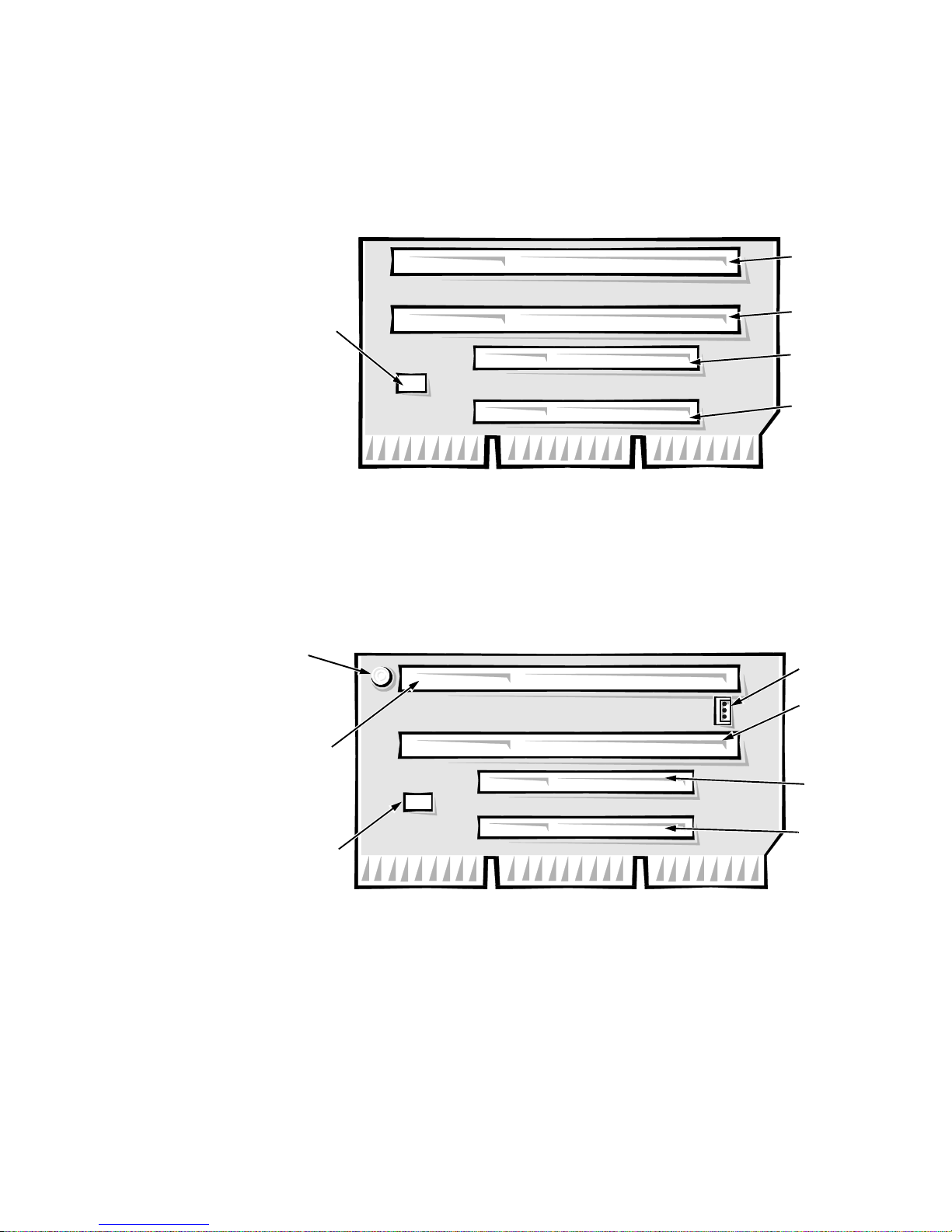
HDLED
connector
ISA2
connector
ISA1
connector
PCI2
connector
PCI1
connector
ISA2
connector
LED
PCI2
connector
PCI1
connector
HDLED
ISA1
connector
P1
connector
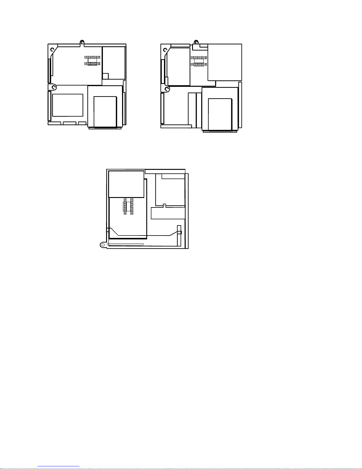
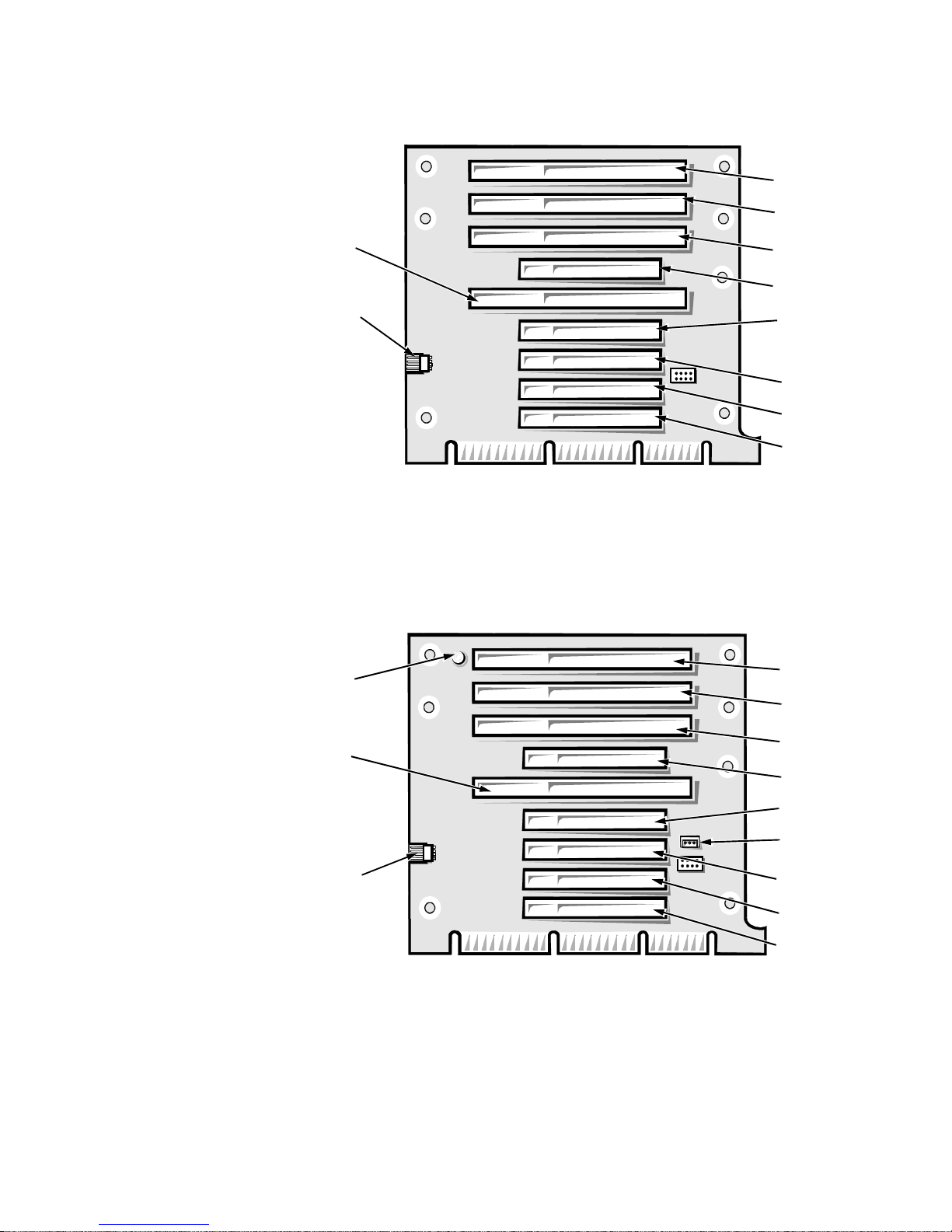
The low-profile computers have three expansion-card slots. The riser board has
two ISA expansion-card connectors and two PCI expansion-card connectors.
One PCI expansion-card connector and one ISA expansion-card connector
share a single expansion-card slot, resulting in a total of three expansion-card
slots (see Figure 1-6). The low-profile computers have a passive riser board,
with no PCI-to-PCI bridge.
Figure 1-6. Riser Board for the Low-Profile Computers
If you have the EM version of the low-profile computer, the riser board for the
computer is different (see Figure 1-7). P1 is the network card connection on the
riser board. If the LED is on, the riser is receiving power, if it is off, the riser is
not receiving power.
Figure 1-7. EM Riser Board for the Low-Profile Computers
Midsize Computer’s Expansion-Card Slots
The midsize computers have five expansion-card slots and a passive riser board,
with no PCI-to-PCI bridge. The computer has three ISA expansion-card connectors and three PCI expansion-card connectors. One PCI expansion-card
1-8
Dell OptiPlex Gn and Gn+ Systems Service Manual
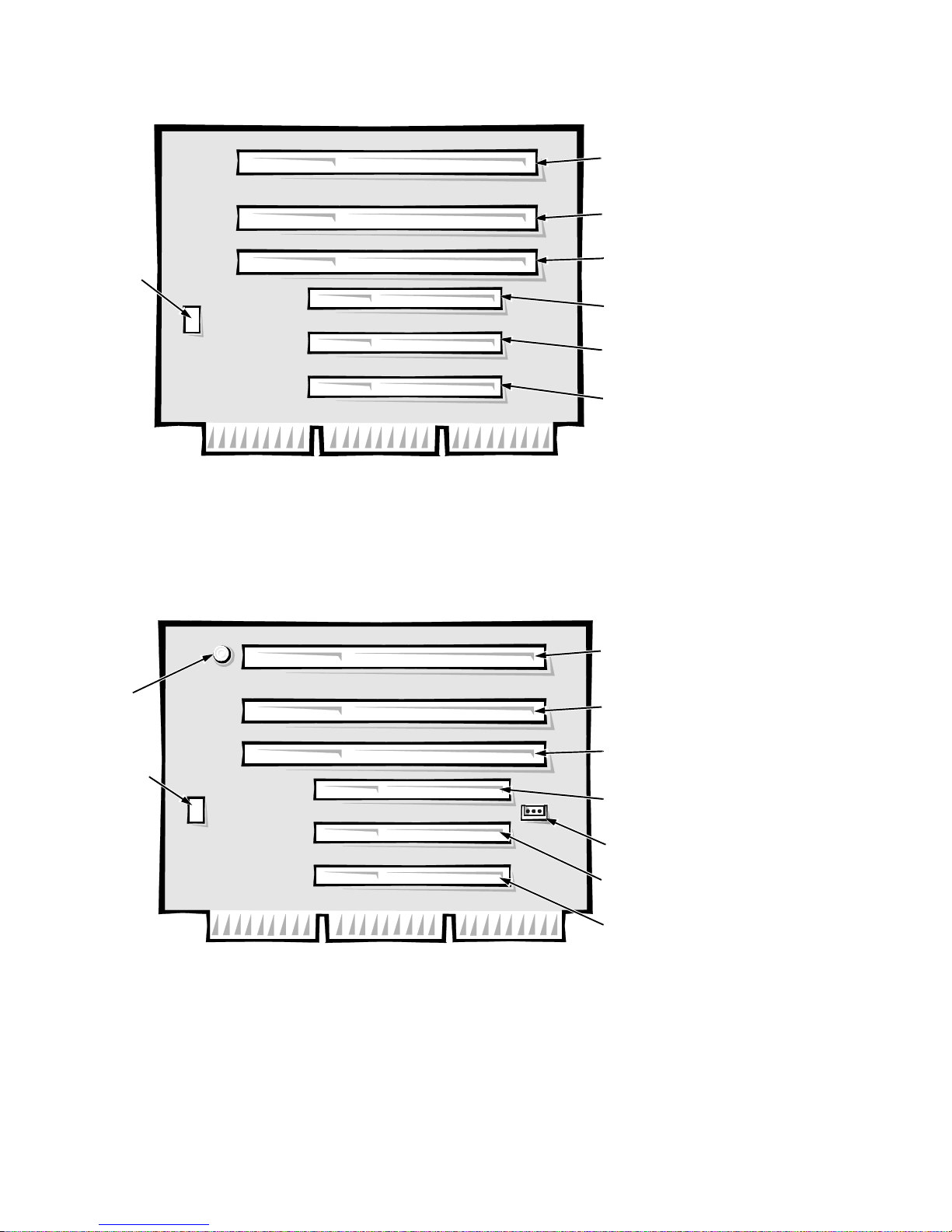
connector and one ISA expansion-card connector share a single expansion-card
slot, resulting in a total of five expansion-card slots (see Figure 1-8).
ISA3
connector
ISA2
connector
HDLED
connector
ISA1
connector
PCI3
connector
PCI2
connector
PCI1
connector
Figure 1-8. Riser Board for the Midsize Computers
If you have the EM version of the midsize computer, the riser board for the
computer is different (see Figure 1-9). P1 is the network card connection on the
riser board. If the LED is on, the riser is receiving power, if it is off, the riser is
not receiving power.
ISA3
connector
LED
ISA2
connector
HDLED
connector
Figure 1-9. EM Riser Board for the Midsize Computers
Mini Tower Computer’s Expansion-Card Slots
The mini tower computers have seven expansion-card slots. The riser board has
four ISA expansion-card connectors and five PCI expansion-card connectors.
ISA1
connector
PCI3
connector
P1
connector
PCI2
connector
PCI1
connector
System Overvi ew 1-9
Two PCI expansion-card connectors share expansion-card slots with ISA con-
ISA4
PCI1
PCI5
ISA2
PCI2
PCI3
ISA3
PCI4
ISA1
HDLED
connector
ISA4
ISA1
HDLED
connector
P1
connector
PCI1
PCI5
ISA2
PCI2
PCI3
ISA3
LED
PCI4
nectors, resulting in a total of seven expansion-card slots (see Figure 1-10). The
riser board is active, incorporating PCI-to-PCI bridging.
Figure 1-10. Riser Board for the Mini Tower Computers
If you have the EM version of the minitower computer, the riser board for the
computer is different (see Figure 1-11). P1 is the network card connection on
the riser board. If the LED is on, the riser is receiving power, if it is off, the riser
is not receiving power.
Figure 1-11. EM Riser Board for the Mini Tower Computers
Hard-Disk Drive Options
The following subsections provide service-related information about hard-disk
drive options in the low-profile, midsize, and mini tower computers.
1-10
Dell OptiPlex Gn and Gn+ Systems Service Manual

Low-Profile Computers
The hard-disk drive assembly (consisting of the hard-disk drive and the harddisk drive bracket) is located inside the chassis at the left front of the computer
and is attached to the bottom of the chassis. One EIDE 1-inch-high hard-disk
drive can be mounted on the hard-disk drive bracket.
Midsize Computers
The hard-disk drive bracket is located next to the externally accessible drive
bays at the front of the computer. The hard-disk drive bracket can contain either
one or two 1-inch-high EIDE hard-disk drives, or one 1-inch-high EIDE harddisk drive and one 1.6-inch-high EIDE hard-disk drive.
Mini Tower Computers
The hard-disk drive bracket is located beneath the externally accessible drive
bays at the front of the computer. The hard-disk drive bracket can contain either
one or two 1-inch-high EIDE hard-disk drives, or one 1-inch-high EIDE harddisk drive and one 1.6-inch-high EIDE hard-disk drive.
Enhanced Dual-Interface EIDE Subsystem
The EIDE subsystem provides two mode-4, DMA bus-mastered EIDE interfaces, each of which can support up to two EIDE devices. The EIDE controller
attaches to the high-speed PCI local bus.
The primary EIDE interface (IDE1) supports up to two high-performance EIDE
devices. The computer’s boot drive should be connected to this connection (the
primary EIDE interface).
The secondary EIDE interface (IDE2) also supports up to two highperformance EIDE devices, typically EIDE tape drives or CD-ROM drives.
NOTE: The externally accessible drive bays at the front of the computer are
normally used for diskette drives, CD-ROM drives, and/or tape drives. Harddisk drives should be installed in the internal hard-disk drive positions
described in “Hard-Disk Drive Options” found earlier in this chapter. For
detailed information about the data storage subsystem, see Chapter 7, “Installing Drives,” in the Reference and Installation Guide.
Built-In Video Controller
The video subsystem consists of a high-speed, high-resolution S3 Trio
64V2 86C785 video controller built into the system board. Because the video
controller connects to the PCI bus rather than to the ISA bus, communication
between the video subsystem and the microprocessor is much faster. The PCI
bus operates at a frequency of 33 MHz as opposed to the 8.25-MHz operating
frequency of the ISA bus.
The built-in video controller includes 2 MB of video memory built into the system board.
System Overvi ew 1-11
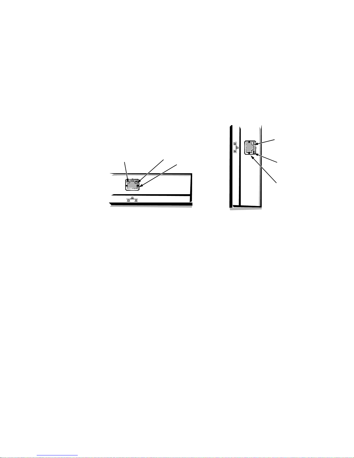
Optional NIC
NIC connector
link integrity
indicator
low-profile and
midsize computers
activity
indicator
activity
indicator
link integrity
indicator
mini tower
computer
NIC connector
The Dell OptiPlex Gn+ computers have a built-in integrated 10/100-Mbps
3Com® PCI 3C905 Ethernet NIC subsystem. The NIC provides all the functions of a separate 3Com 3C905 network expansion card and supports the
100BASE-TX Ethernet standards. Category 5 wiring and connections must be
used.
The standard integrated 3Com 3C905 NIC does not support the Wakeup On
LAN feature. Wakeup On LAN capability is provided by an optional expansion
card with a +5 VFP cable that connects to the P1 connector on the riser board.
The NIC subsystem connects to the Ethernet network through an RJ45 connector on the back panel of the computer.
Figure 1-12. NIC Connector on I/O Panel
The NIC (RJ45) connector and NIC interface circuitry are mounted on the system board and have the following indicators:
A yellow activity indicator flashes when the computer is transmitting or
•
receiving network data. A high volume of network traffic may make this
indicator appear to be in a steady “on” state.
A green link integrity indicator lights up when a good connection exists
•
between the network and the NIC. When the green indicator is off, the computer is not detecting a physical connection to the network.
Chapter 4, “Using Integrated Devices,” in the Reference and Installation Guide
provides instructions for connecting the computer to, and configuring it for , use
on an Ethernet network.
Floor Stand
The low-profile and midsize computers can be used in a vertical orientation
using an available floor stand. The floor stand is attached to the left side of the
low-profile or midsize computer. The floor stand is permanently attached to the
bottom of the mini tower computer.
1-12
Dell OptiPlex Gn and Gn+ Systems Service Manual

C
omputer Service
The following subsections provide service-related information about the
computer.
Computer Power Supply
The low-profile computers have a 145-W computer power supply, whereas the
midsize and mini tower computers have a 200-W computer power supply. Both
computer power supplies can operate from an AC power source of 115 VAC at
60 Hz or 230 VAC at 50 Hz. The computer power supply provides the DC operating voltages and currents listed in Table 1-1.
NOTE: The power supply produces DC voltages only under its loaded condition. Therefore, when you measure these voltages, the DC power connectors
must be connected to their corresponding power input connectors on the system
board or drives.
.
Table 1-1. DC Voltage Ranges
Voltage Range Maximum Output Current
+3.3 VDC +3.15 to +3.45 VDC
12.0 A1 (low-profile computers)
14.0 A
1
(midsize and mini tower
computers)
+5 VDC +4.75 to +5.25 VDC
18.0 A
1
(low-profile computers)
22.0 A1 (midsize and mini tower
computers)
+12 VDC +11.40 to +12.60 VDC
3.0 A
6.0 A
2
(low-profile computers)
2
(midsize and mini tower
computers)
–12 VDC –10.80 to –13.20 VDC 0.3 A (low-profile computers)
0.3 A (midsize and mini tower
computers)
–5 VDC –4.50 to –5.50 VDC 0.3 A (low-profile computers)
0.3 A (midsize and mini tower
computers)
+5 VFP
1
The combined load on the +5-VDC and +3.3-VDC outputs should not exceed 105 W on
2
Withstands surges of up to 11.0 A to support disk start-up operations.
3
VFP (volts flea power) — sometimes called “standby power.”
3
the low-profile computers or 140 W on the midsize and mini tower computers.
+4.75 to +5.25 VDC 1.2 A
System Overvi ew 1-13
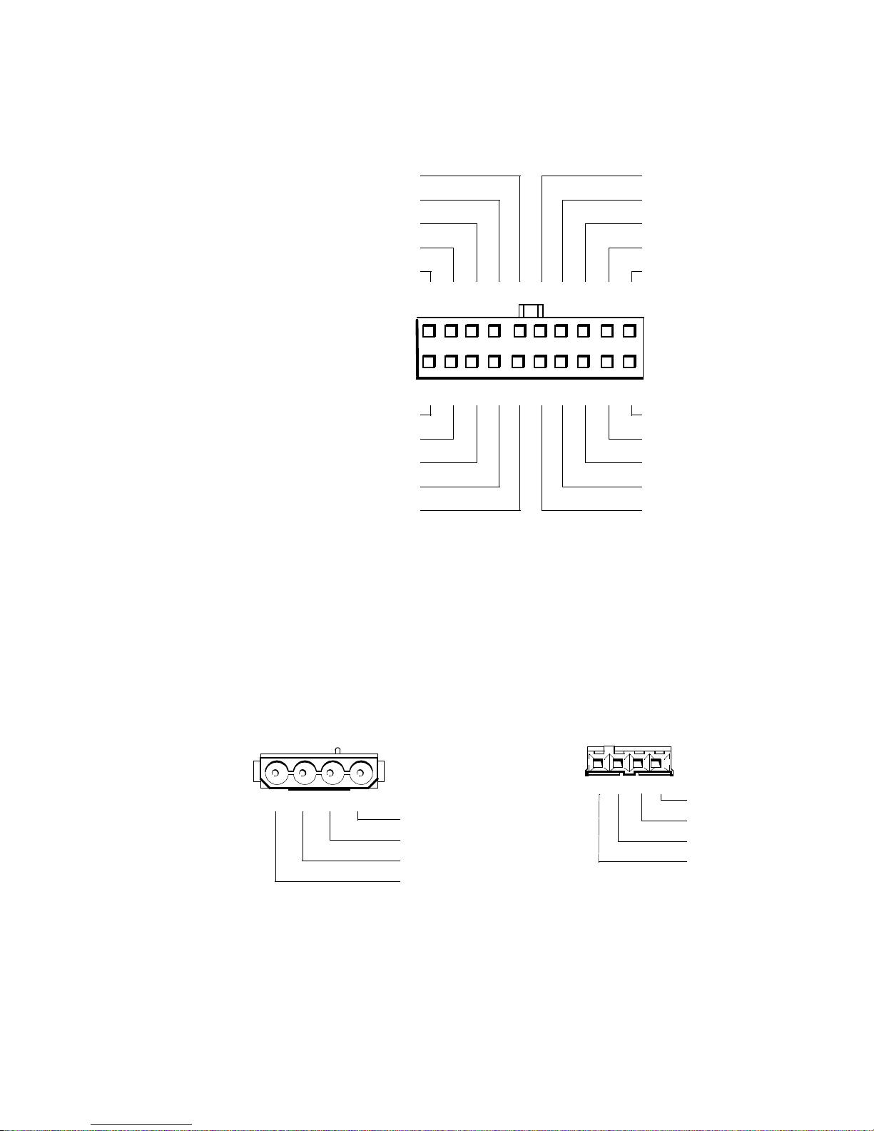
Pin Assignments for the DC Power Connectors
11
1
PWRGOOD
3
(orange)
–12 VDC (blue)
+12 VDC (yellow)
+5 VFP (purple)
common (black)
2 3 4 5 6 7 8 9 10
12 13 14 15 16 17 18 19 20
P1
+5 VDC (red)
+5 VDC (red)
+5 VDC (red)
+5 VDC (red)
+5 VDC (red)
+5 VDC (red)
common (black)
common (black)
common (black)
PSON#1 (grey)
common (black)
common (black)
common (black)
–5 VDC (white)
TFSC
2
(brown)
1 2 3 4
+5 VDC (red)
common (black)
common (black)
+12 VDC (yellow)
1 2 3 4
+5 VDC (red)
common (black)
common (black)
+12 VDC (yellow)
P2, P3, P5, P6, P9
P4
The power-supply output voltages can be measured at the back (wire side) of
the connectors without disconnecting them. Figures 1-10 through 1-12 show the
wire side of the connectors.
1
Pin 11 — PSON# should measure between +4 and +5 VDC except when the power button
on the front panel is pressed, taking PSON# to its active-low state.
2
Pin 19 — Thermal fan-speed control (TFSC) is a power-supply input signal used to control
the power-supply fan speed.
3
Pin 5 — PWRGOOD should measure between +4 and +5 VDC when the power supply is
operating to indicate that all power-supply output voltages are within the ranges specified
in Table 1-1.
Figure 1-13. DC Power Connector P1
Figure 1-14. DC Power Connectors P2 (Midsize and Mini Tower),
P3, P4, P5, P6, and P9
1-14
Dell OptiPlex Gn and Gn+ Systems Service Manual
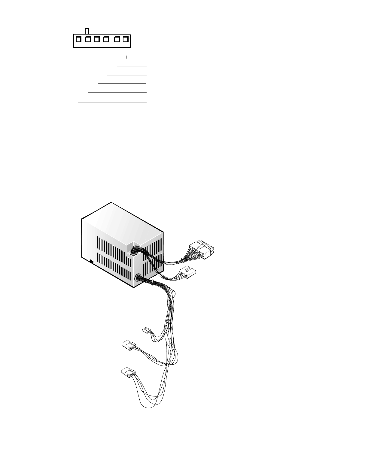
P2, P7
1234
5
6
+3.3 VDC (blue/white)
+3.3 VDC (blue/white)
+3.3 VDC (blue/white)
common (black)
common (black)
common (black)
Figure 1-15. DC Power Connectors P2 (Low-Profile) and P7
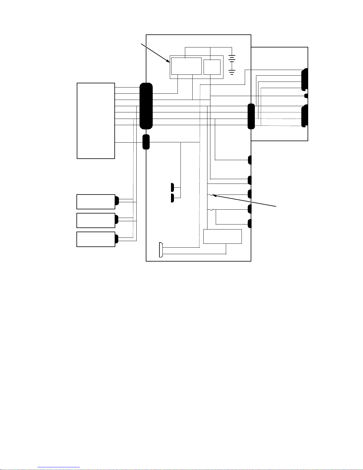
DC Power Distribution
Figures 1-13 through 1-17 provide the following information about DC power
distribution:
Power-supply connector identification
•
Power cable connections for diskette, tape, CD-ROM, and hard-disk drives
•
Power distribution to sockets and connectors on the system board
•
P1
P2
P4
P3
P5
Figure 1-16. DC Power Cables for the Low-Profile Computers
System Overvi ew 1-15
computer
power supply
keyboard
controller
P1 POWER1
PWRGOOD
PSON#
+5 VFP
+5 VDC
–5 VDC
+12 VDC
–12 VDC
P2
+3.3 VDC
PSON#
+5 VFP
+5 VDC
–5 VDC
+12 VDC
–12 VDC
POWER2
+3 VDC
power
management
logic
RTC/
NVRAM
system board
battery
+5 VDC
–5 VDC
+12 VDC
–12 VDC
RISER
riser board
+3.3 VDC
+5 VDC
+12 VDC
–12 VDC
+5 VFP
+5 VDC
–5 VDC
+12 VDC
–12 VDC
PCI1
PCI2
P1
ISA1
ISA2
optional
drive
3.5-inch
diskette drive
internal
hard-disk drive
Figure 1-17. DC Power Distribution for the Low-Profile Computers
P4
P5
P3
main memory
sockets
DIMM_A
DIMM_B
MICROPROCESSOR
+3.3 VDC
core VCC +2.1 to +3.5 VDC
+12 VDC
+5 VFP
+5 VDC
+5 VDC
+5 VDC
+5 VDC
processor
core regulator
FAN
PANEL
USB
KYBD
MOUSE
fuses (2)
1-16
Dell OptiPlex Gn and Gn+ Systems Service Manual
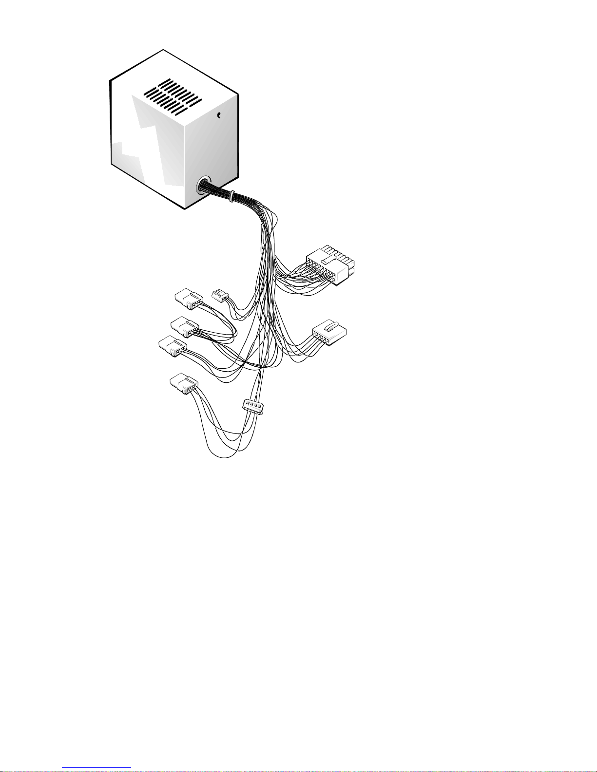
P1
P6
*
P4
P5
*
P9
*
P3
P2
*
Some computers hav e an ad ditional connector (P9 ) that ma y be us e d inst e a d of P5 or P6.
P7
Figure 1-18. DC Power Cables for the Midsize and Mini Tower
Computers
System Overvi ew 1-17
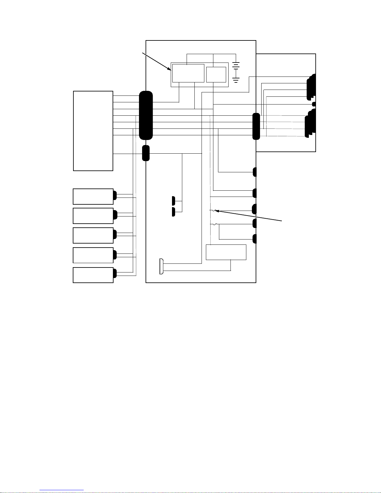
computer
power supply
keyboard
controller
P1
PWRGOOD
PSON#
+5 VFP
+5 VDC
–5 VDC
+12 VDC
–12 VDC
P7
+3.3 VDC
POWER1
PSON#
+5 VFP
+5 VDC
–5 VDC
+12 VDC
–12 VDC
POWER2
+3 VDC
power
management
logic
system board
RTC/
NVRAM
battery
+5 VDC
–5 VDC
+12 VDC
–12 VDC
RISER
riser board
+3.3 VDC
+5 VDC
+12 VDC
–12 VDC
+5 VFP
+5 VDC
–5 VDC
+12 VDC
–12 VDC
PCI1
through
PCI3
P1
ISA1
through
ISA3
+12 VDC
main memory
sockets
DIMM_A
DIMM_B
MICROPROCESSOR
+3.3 VDC
core VCC +2.1 to +3.5 VDC
core regulator
P4
P5
P6
P2
P3
*
*
internal
hard-disk drive
internal
hard-disk drive
3.5-inch
diskette drive
optional
drive
optional
drive
*
Some computers have an additional connector (P9) that may be used instead of P5 or P6.
+5 VFP
+5 VDC
+5 VDC
+5 VDC
+5 VDC
processor
FAN
PANEL
USB
KYBD
MOUSE
Figure 1-19. DC Power Distribution for the Midsize Computers
fuses (2)
1-18
Dell OptiPlex Gn and Gn+ Systems Service Manual
 Loading...