

Dell OptiPlex GM Technical Manualbook

TM
DELL
TM
OPTIPLEX 990
TECHNICAL GUIDEBOOK—
INSIDE THE OPTIPLEX 990

TABLE OF CONTENTS
OVERVIEW
Mini Tower Computer (MT) View 3-4
Desktop Computer (DT) View 5-6
Small Form Factor Computer (SFF) View 7-8
Ultra Small Form Factor Computer (USFF) View
MARKETING SYSTEM CONFIGURATIONS
Operating System, Chipset 11
Processor 12
Memory 13
Drives and Removable Storage, System Expansion Slots 14-15
Graphics/Video Controller 16
External Ports/Connectors 16
Communications—Network Adapter (NIC), Wireless 17
9-10
Audio and Speakers, Keyboard and Mouse 17
Security, Software, Environmental, All-in-One Stands & Mounts, Service and Support 18
DETAILED ENGINEERING SPECIFICATIONS
System Dimensions (Physical) 19
System Expansion Slots 19
System Level Environmental and Operating Conditions 20
Power 21-22
Audio 23
Communications 23-27
Graphics/Video Controller 28-30
Hard Drives 31-39
Optical Drive 40-42
Media Card Reader 43
BIOS Defaults 44
Chassis Enclosure and Ventilation Requirements 45
Environmental Attributes 46
Acoustic Noise Emission Information 47-50
DELL™ OPTIPLEX™ 990 TECHNICAL GUIDEBOOK —VERSION 1.5
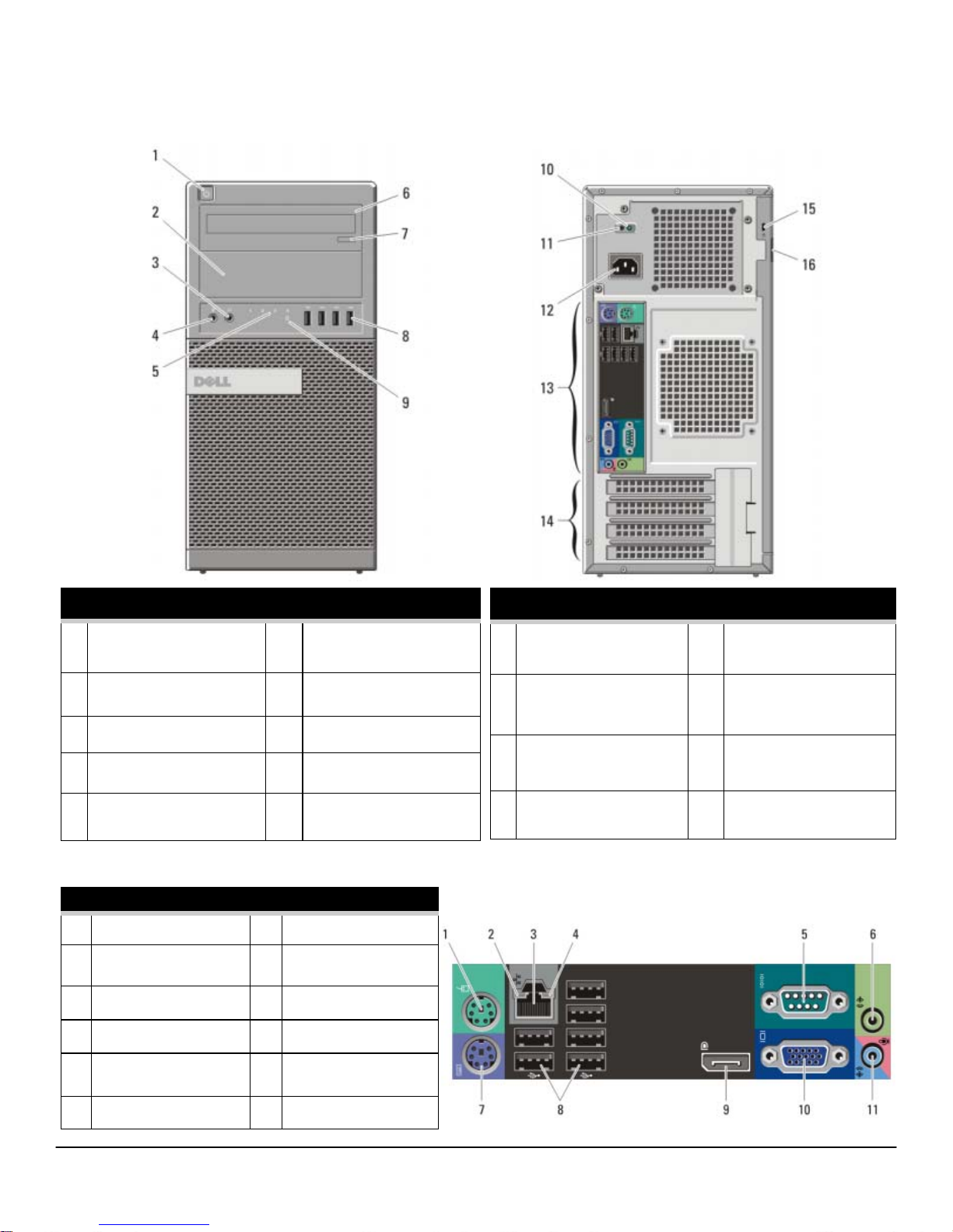
MINI TOWER COMPUTER (MT) VIEW
FRONT VIEW
1
Power Button, Power
6 Optical Drive (optional)
Light
2 Optical Drive Bay
(optional)
3
Headphone Connector
4
Microphone Connector
5
Diagnostic Lights (4)
BACK PANEL CONNECTORS
1 Mouse Connector 7 Keyboard Connector
2 Link Integrity Light 8 USB Connectors (6)
3 Network Connector 9 DisplayPort Connector
4 Network Activity Light 10 VGA Connector
7 Optical Drive Eject Button
8 USB 2.0 Connectors (4)
9
Drive Activity Light
BACK VIEW
10 Power Supply Diagnostic
Light
11 Power Supply Diagnostic
Button
12 Power Connectors 16 Padlock Ring
13 Back Panel Connectors
14 Expansion Card Slots(4)
15 Security Cable Slot
5 Serial Connector 11 Line-in/Microphone
Connector
6 Line-out Connector
3
DELL™ OPTIPLEX™ 990 TECHNICAL GUIDEBOOK —VERSION 1.5
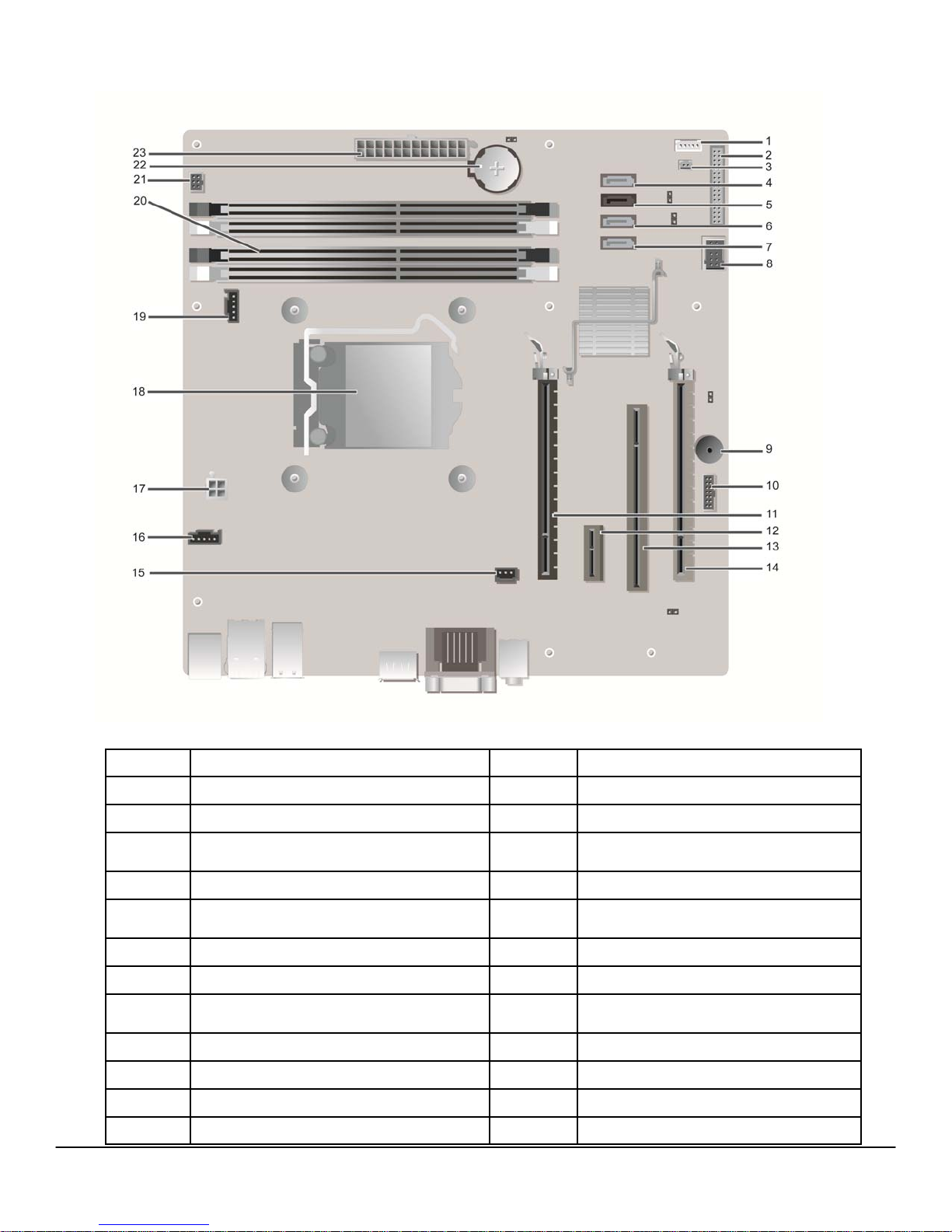
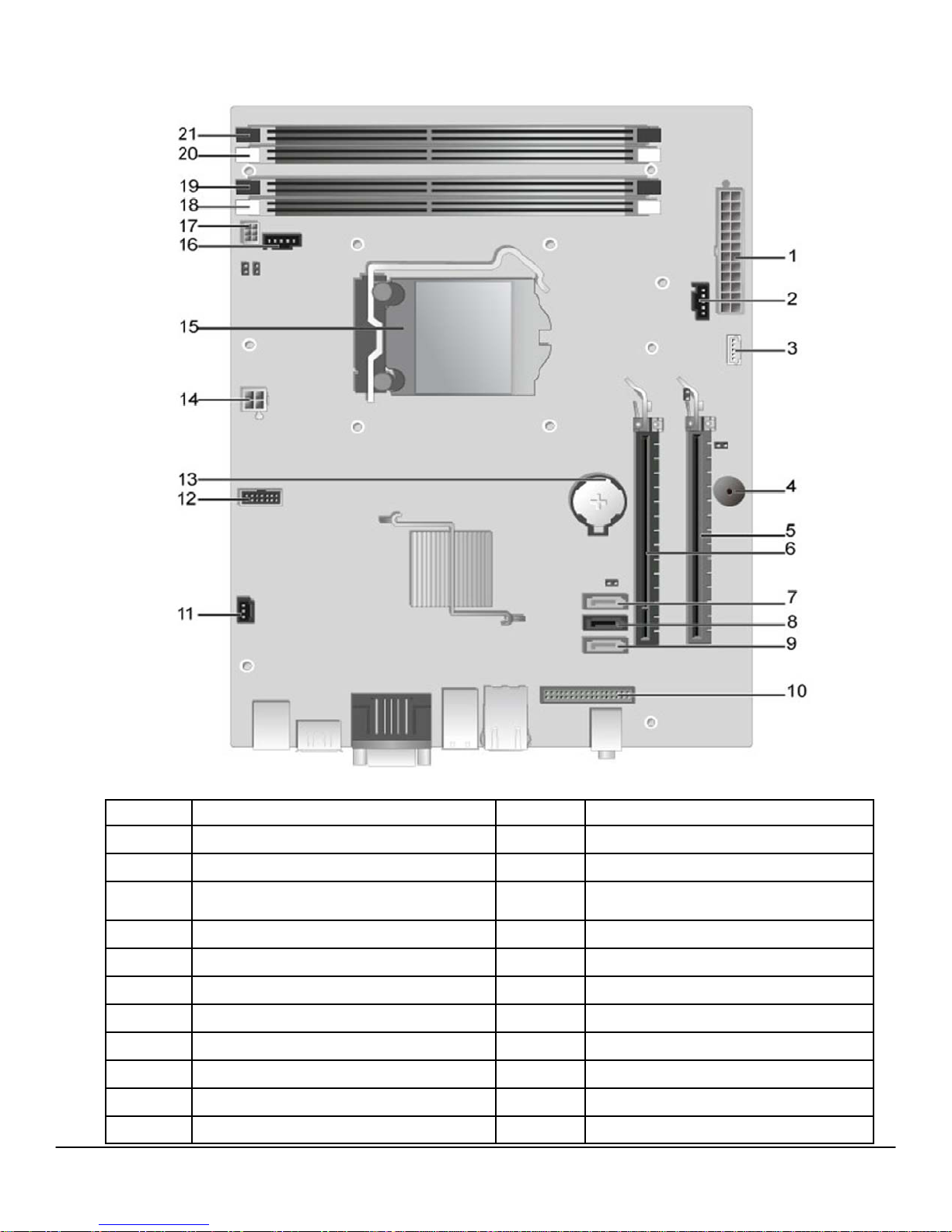
MT System Board Components
Number Name Number Name
1 Internal Speaker Connector (INT_SPKR) 13 PCI Connector(SLOT3)
2 Front IO Connector (FRONTPANEL) 14 PCI-e 4x Connector(SLOT4)
3 Thermal Sensor Connector(THRM_2) 15
4 SATA 0 Connector(SATA0) 16 System Fan Connector (FAN_HDD)
5 SATA 1 Connector(SATA1) 17
6 SATA 2 Connector(SATA2) 18 Processor Connector (N/A)
7 SATA 3 Connector(SATA3) 19 CPU fan Connector (FAN_CPU)
8 Internal USB Connector (INT_USB) 20
9 Buzzer (BEEP) 21 Power Switch Connector (PWR_SW)
10 LPC Debug Connector (LPC_DEBUG) 22 Battery Connector (BATTERY)
11 PCI-e 16x Connector(SLOT1) 23 P1 Power Connector (POWER)
12 PCI-e 1x Connector(SLOT2)
Intrusion Switch Connector
(INTRUDER)
P2 Power Connector
(12V_PWRCONN)
Memory Connectors(DIMM1, DIMM2,
DIMM3, DIMM4)
4
DELL™ OPTIPLEX™ 990 TECHNICAL GUIDEBOOK —VERSION 1.5
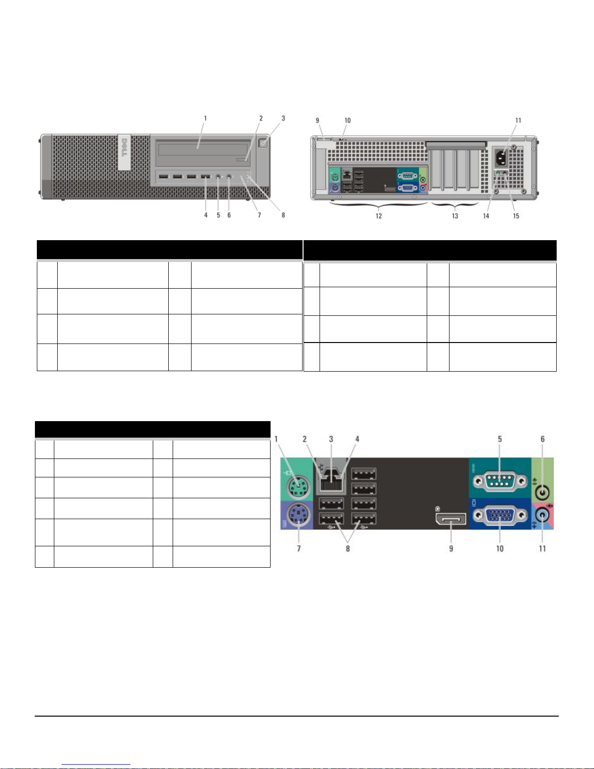
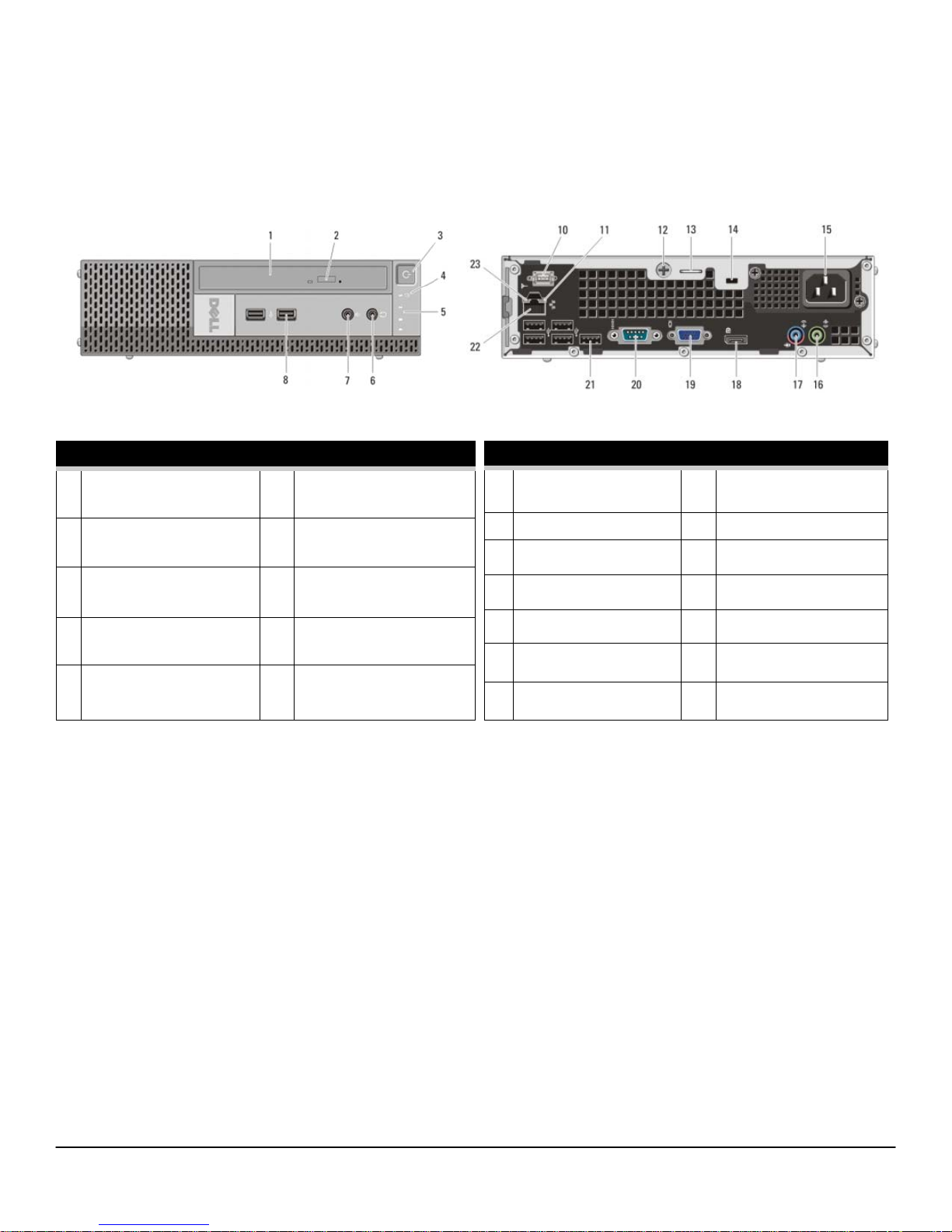
DESKTOP COMPUTER (DT) VIEW
FRONT VIEW
1 Optical Drive
2 Optical Drive Eject Button 6
3
Power Button, Power
5
Microphone Connector
Headphone Connector
7
Drive Activity Light
Light
4 USB Connectors (4) 8
BACK PANEL CONNECTORS
1 Mouse Connector 7 Keyboard Connector
2 Link Integrity Light 8 USB Connectors (6)
3 Network Connector 9 DisplayPort Connector
4 Network Activity Light 10 VGA Connector
5 Serial Connector 11 Line-in/Microphone
Diagnostic Lights (4)
Connector
BACK VIEW
9 Padlock Ring 13 Expansion Card Slots(4)
10 Security Cable Slot 14 Power Supply Diagnostic
Light
11 Power Connectors 15 Power Supply Diagnostic
Button
12 Back Panel Connectors
6 Line-out Connector
5

DELL™ OPTIPLEX™ 990 TECHNICAL GUIDEBOOK —VERSION 1.5
DT System Board Components
Number Name Number Name
1 Internal Speaker Connector
(INT_SPKR)
2 Front IO Connector (FRONTPANEL) 14 Intrusion Switch Connector
3 Thermal Sensor Connector(THRM_2) 15 Thermal Sensor Connector(THRM_1)
4 SATA 0 Connector(SATA0) 16 System Fan Connector (FAN_HDD)
5 SATA 1 Connector(SATA1) 17 P2 Power Connector
6 SATA 2 Connector(SATA2) 18 Processor Connector (N/A)
7 Internal USB Connector (INT_USB) 19 CPU Fan Connector (FAN_CPU)
8 PCI-e 16x Connector(SLOT1) 20 Memory Connectors(DIMM1, DIMM2,
9 PCI-e 4x Connector(SLOT4) 21 Power Switch Connector (PWR_SW)
10 Buzzer (BEEP) 22 Battery Connector (BATTERY)
11 LPC Debug Connector (LPC_DEBUG) 23 P1 Power Connector (POWER)
12 PCI Connector(SLOT3)
13 PCI-e 1x Connector(SLOT2)
(INTRUDER)
(12V_PWRCONN)
DIMM3, DIMM4)
6
DELL™ OPTIPLEX™ 990 TECHNICAL GUIDEBOOK —VERSION 1.5
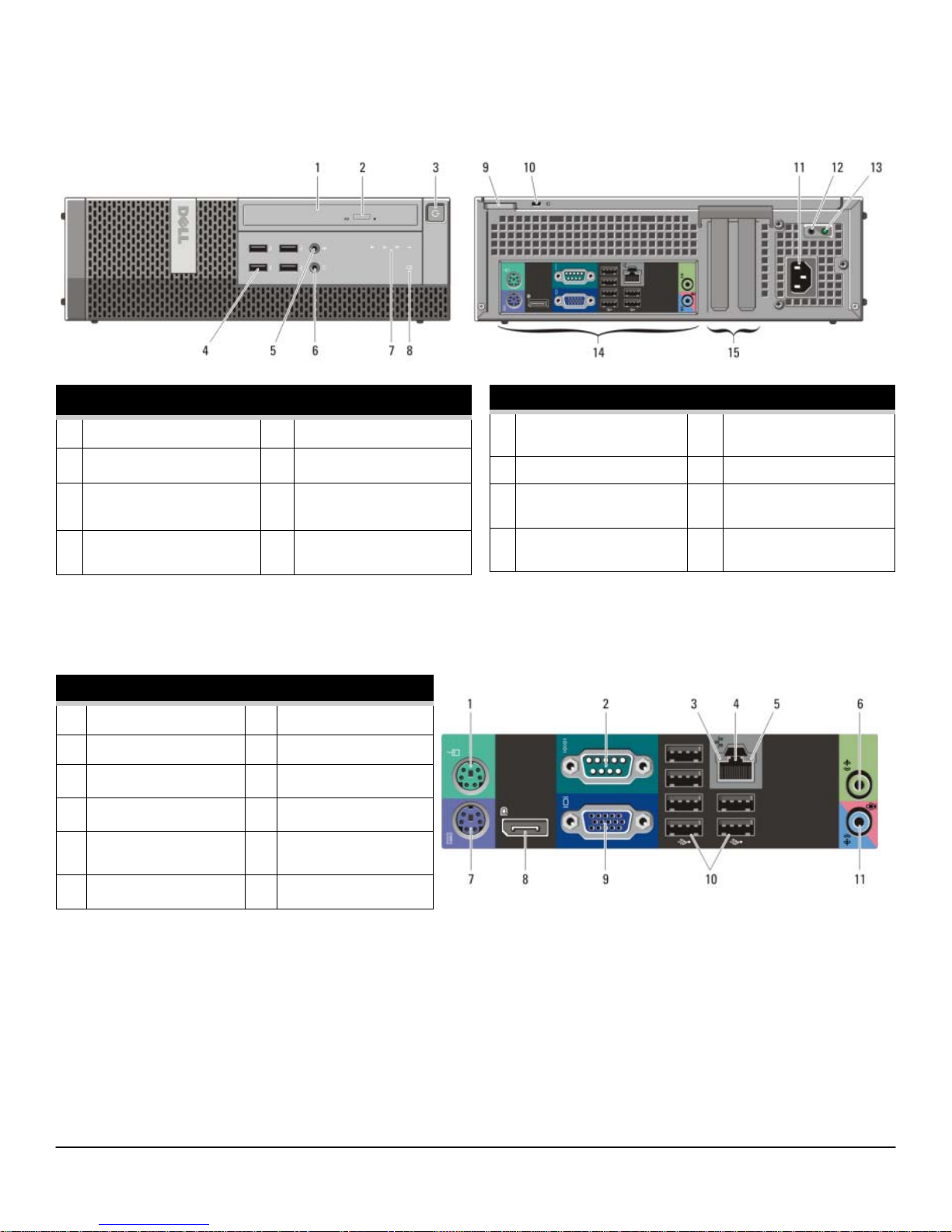
SMALL FORM FACTOR COMPUTER (SFF) VIEW
FRONT VIEW
1 Optical Drive 5
2 Optical Drive Eject Button 6
3
Power Button, Power
Light
4 USB 2.0 Connectors (4) 8
BACK PANEL CONNECTORS
1 Mouse Connector 7 Keyboard Connector
2 Serial Connector 8 DisplayPort Connector
3 Link Integrity Light 9 VGA Connector
4 Network Connector 10 USB Connectors (6)
5 Network Activity Light 11 Line-in/Microphone
Microphone Connector
Headphone Connector
7
Diagnostic Lights (4)
Drive Activity Light
Connector
BACK VIEW
9 Padlock Ring 13 Power Supply Diagnostic
Light
10 Security Cable Slot 14 Back Panel Connectors
11 Power Connectors 15 Expansion Card Slots(2)
12 Power Supply Diagnostic
Button
6 Line-out Connector
7
DELL™ OPTIPLEX™ 990 TECHNICAL GUIDEBOOK —VERSION 1.5
SFF System Board Components
Number Name Number Name
1 P1 power Connector (POWER) 12 LPC debug Connector (LPC_DEBUG)
2 System fan Connector (FAN_HDD) 13 Battery Connector (BATTERY)
3 Internal Speaker Connector (INT_SPKR) 14 P2 Power Connector
4 Buzzer (BEEP) 15 Processor Connector (N/A)
5 PCI-e 4x Connector(SLOT2) 16 CPU Fan Connector (FAN_CPU)
6 PCI-e 16x Connector(SLOT1) 17 Power Switch Connector (PWR_SW)
7 SATA 2 Connector(SATA2) 18 Memory Connector(DIMM3)
8 SATA 1 Connector(SATA1) 19 Memory Connector(DIMM1)
9 SATA 0 Connector(SATA0) 20 Memory Connector(DIMM4)
10 Front IO Connector (FRONTPANEL) 21 Memory Connector(DIMM2)
11 Intrusion Switch Connector (INTRUDER)
(12V_PWRCONN)
8
DELL™ OPTIPLEX™ 990 TECHNICAL GUIDEBOOK —VERSION 1.5
ULTRA SMALL FORM FACTOR COMPUTER (USFF) VIEW
FRONT VIEW
1 Optical Drive
2 Optical Drive Eject Button 7
3
Power Button, Power
Light
4
Drive Activity Light
5
Diagnostic Lights (4)
6
Headphone Connector
Microphone Connector
8 USB Connectors (2)
BACK VIEW
10 Wi-Fi Antenna (optional) 17 Line-in/ Microphone
Connector
11 Network Activity Light 18 DisplayPort Connector
12 Captive Thumbscrew 19 VGA Connector
13 Padlock Ring 20 Serial Connector
14 Security Cable Slot 21 USB Connectors (5)
15 Power Connector 22 Network Connector
16 Line-Out Connector 23 Link Integrity Light
9

DELL™ OPTIPLEX™ 990 TECHNICAL GUIDEBOOK —VERSION 1.5
USFF System Board Components
Number Name Number Name
1 Front Panel Connector (FRONTPANEL) 10 SATA 1 Connector(SATA_1)
2 Memory Connector(DIMM_2) 11 SATA 0 Connector(SATA_0)
3 Memory Connector(DIMM_1) 12 P1 Power Connector(POWER1)
4 CPU Fan Connector (FAN_CPU) 13
5 Internal Speaker Connector (INT_SPKR) 14
6 Buzzer (BEEP) 15 LPC Debug Connector (LPC_DEBUG)
7 Front IO Connector (F_USB_AUDIO) 16 P2 Power Connector(12V_PWRCONN)
8 System Fan Connector (FAN_HDD) 17 Processor Connector (N/A)
9 Mini-PCI Socket (PCIE_MINICARD) 18 Battery Connector (BATTERY)
HDD-ODD Power Connector
(HDD_ODD_POWER)
Intrusion Switch Connector
(INTRUDER)
10
DELL™ OPTIPLEX™ 990 TECHNICAL GUIDEBOOK —VERSION 1.5
MARKETING SYSTEM CONFIGURATIONS
NOTE: O erings may vary by country. For more information regarding the confi guration of your computer, click
Start>Help and Support and select the option to view information about your computer.
OPERATING SYSTEM
Windows 7® operating system
Windows Vista® operating system
Windows XP® operating system
Other
OS Media Support (optional) X X X X
MT DT SFF USFF
Microsoft® Windows 7® Home Basic (32 and 64 bit),
Microsoft® Windows 7® Home Basic SP1 (32 and 64 bit),
Microsoft® Windows 7® Home Premium (32 and 64 bit),
Microsoft® Windows 7® Professional (32 and 64 bit),
Microsoft® Windows 7® Ultimate (32 and 64 bit),
Windows Vista® Home Basic SP2 (32 bits),
Windows Vista® Business SP2 (32 and 64 bit),
Windows Vista® Ultimate SP2 (32 bit)
Basic Driver support only via Dell.com
FreeDOS for (N-series),
Ubuntu® Linux version 10.10 (China only)
CHIPSET
Chipset Intel Q67 Express Chipset
Non-volatile memory on chipset
MT DT SFF USFF
BIOS Configuration SPI (Serial Peripheral Interface)
TPM 1.2 Security Device (Trusted Platform Module)1 18KB located at TPM1.2 on chipset
Non-TPM Available in select countries
NIC EEPROM
64Mbit (8MB) &16Mbit(2MB) located at SPI_FLASH on chipset
LOM configuration contained within SPI_FLASH – no dedicated
LOM EEPROM
11

DELL™ OPTIPLEX™ 990 TECHNICAL GUIDEBOOK —VERSION 1.5
PROCESSOR
NOTE: Global Standard Products (GSP) are a subset of Dell’s relationship products that are managed for availability and synchronized transitions on a worldwide basis. They ensure the same platform is available for purchase globally. This allows customers to
reduce the number of configurations managed on a worldwide basis, thereby reducing their costs. They also enable companies
to implement global IT standards by locking in specific product configurations worldwide. The following GSP processors identified below will be made available to Dell customers.
NOTE: Processor numbers are not a measure of performance. Processor availability subject to change and may vary by region/
country.
Intel® Quad Core Processors
Intel® Core™ i7 2600 / 3.40GHz, 8M, VT-x, VT-d, TXT
(vPro™), 95W
Intel® Core™ i7 2600S / 2.80GHz, 8M, VT-x, VT-d, TXT
(vPro™), 65W
Intel® Core™ i5 2500 / 3.30GHz, 6M, VT-x, VT-d, TXT
(vPro™), 95W
Intel® Core™ i5 2500S / 2.70GHz, 6M, VT-x, VT-d, TXT
(vPro™), 65W
Intel® Core™ i5 2400 / 3.10GHz, 6M, VT-x, VT-d, TXT
(vPro™), 95W
Intel® Core™ i5 2400S / 2.50GHz, 6M, VT-x, VT-d, TXT
(vPro™), 65W
Intel® Dual Core Processors
Intel® Core™ i3 2120 / 3.30GHz, 3M, VT-x, 65W X X X X
Intel® Core™ i3 2100 / 3.10GHz, 3M, VT-x, 65W X X X X
Intel® Pentium™ G850 / 3.10GHz, 3M, VT-x, 65W X X X X
Intel® Pentium™ G840 / 3.10GHz, 3M, VT-x, 65W X X X X
MT DT SFF USFF
X-GSP X-GSP X-GSP
X-GSP
X-GSP X-GSP X-GSP
X-GSP
X-GSP X-GSP X-GSP
X-GSP
Intel® Pentium™ G620 / 3.10GHz, 3M, VT-x, 65W X X X X
12

DELL™ OPTIPLEX™ 990 TECHNICAL GUIDEBOOK —VERSION 1.5
MEMORY
NOTE: Memory modules should be installed in pairs of matched memory size, speed, and technology. If the memory modules
are not installed in matched pairs, the computer will continue to operate, but with a slight reduction in performance. The entire
16GB memory range is available to 64-bit operating systems.
MT DT SFF USFF
Type: DDR3 Synch DRAM Non-ECC Memory 1333MHz
DIMM Slots 4 4 4 2
DIMM Capacities Up to 4GB Up to 4GB Up to 4GB Up to 4GB
Minimum Memory 1GB 1GB 1GB 1GB
1
Maximum System Memory 16GB
16GB1 16GB1 8GB1
Memory configurations
1
16GB
DDR3, 1333MHz, (4 DIMM) X X X
8GB1 DDR3, 1333MHz, (2 DIMM) X X X X
1
4GB
DDR3, 1333MHz, (2 DIMM) X X X
1
DDR3, 1333MHz, (1 DIMM) X
4GB
3GB DDR3, 1333MHz, (2 DIMM) X X X X
2GB DDR3, 1333MHz, (2 DIMM) X X X
2GB DDR3, 1333MHz, (1 DIMM)
X
1GB DDR3, 1333MHz, (1 DIMM) X X X X
1
The total amount of available memory will be less than 4GB. The amount less depends on the actual system configuration. To fully utilize 4GB or
more of memory requires a 64-bit enabled processor and 64-bit operating system.
13
DELL™ OPTIPLEX™ 990 TECHNICAL GUIDEBOOK —VERSION 1.5
DRIVES AND REMOVABLE STORAGE
Bays:
5.25-inch Optical Bay Supported (External) 2 1 1 1
Optical Drives Supported (maximum) 2 1 1 (slim-line) 1 (slim-line)
Hard Drive Bay Supported (Internal) 2 1 1 1
Hard Drives Supported 3.5”/2.5” (maximum) 2/2 1/2 1/2 0/1
Interface:
SATA 2.0 2 1 1 0
SATA 3.0 2 2 2 2
3.5” Hard Drives:
1TB1 SATA 7200 RPM HDD X X X
500GB1 SATA 7200 RPM HDD X X X
320GB1 SATA 7200 RPM HDD X X X
MT DT SFF USFF
250GB1 SATA 7200 RPM HDD X X X
2.5” Hard Drives: (Hybrid drive includes 4GB NAND Flash for greater performance)
128GB1 SATA Solid State Drive X X X X
1
500GB
SATA 7200 RPM Hybrid HDD X X X X
320GB1 SATA 7200 RPM Opal SED HDD X X X X
500GB1 SATA 7200 RPM HDD X X X X
250GB1 SATA 7200 RPM HDD X X X X
RAID 1 Data Protection: (includes two matching capacity/speed hard drives)
1
SATA 7200 RPM HDD (3.5”) X
1TB
1
500GB
320GB
250GB
SATA 7200 RPM HDD (3.5”) X
1
SATA 7200 RPM HDD (3.5”) X
1
SATA 7200 RPM HDD (3.5”) X
500GB1 SATA 7200 RPM Hybrid HDD (2.5”) X X X
500GB
250GB
1
SATA 7200 RPM HDD (2.5”) X X X
1
SATA 7200 RPM HDD (2.5”) X X X
14

DELL™ OPTIPLEX™ 990 TECHNICAL GUIDEBOOK —VERSION 1.5
DRIVES AND REMOVABLE STORAGE
MT DT SFF USFF
RAID 0 Performance: (includes two matching capacity/speed hard drives)
1
SATA 7200 RPM HDD (3.5”) X
1TB
1
500GB
SATA 7200 RPM HDD (3.5”) X
320GB1 SATA 7200 RPM HDD (3.5”) X
250GB1 SATA 7200 RPM HDD (3.5”) X
500GB1 SATA 7200 RPM Hybrid HDD (2.5”) X X X
500GB1 SATA 7200 RPM HDD (2.5”) X X X
250GB1 SATA 7200 RPM HDD (2.5”) X X X
Optical Drive: (SFF/USFF require slim-line optical drive)
Blu-ray Writer SATA 1.5Gbit/s X X X X
2
DVD+/-RW
DVD-ROM
SATA 1.5Gbit/s X X X X
3
SATA 1.5Gbit/s X X X X
Media Card Reader: (requires slim line optical)
Dell 19 in 1 Media Card Reader X X
NOTE: Dell 19 in 1 Media Card Reader (MCR) is supported via a F5 to F3 bay converter on the MT and DT and may require a slim
line optical drive depending on selectable configuration. MCR is not available on the SFF and USFF.
SYSTEM EXPANSION SLOTS
NOTE: See Detailed Engineering Specifications for supported voltage, maximum wattage and card dimensions.
NOTE: Add in card location and priority: PCI: 1394; PCIe x16: GFX, USB 3.0, Serial, Parallel/Serial, NIC, Wireless; PCIe x4: GFX,
USB 3.0, Serial, Parallel/Serial, NIC, Wireless; PCIe x1: USB 3.0, Serial, Parallel/Serial, NIC, Wireless
MT DT SFF USFF
PCI Slot 1 1 0 0
PCIe x16 Slot 1 1 1 0
PCIe x16 (wired x4) Slot 1 1 1 0
PCIe x1 Slot 1 1 0 0
Half mini-PCIe connector 0 0 0 1
Serial ATA (SATA) connectors 4 3 3 2
1
For hard drives, GB means 1 billion bytes; actual capacity varies with preloaded material and operating environment and will be less.
2
Discs burned with this drive may not be compatible with some existing drives and players; using DVD+R media provides maximum compatibility.
3
DVD-ROM drives may have write-capable hardware that has been disabled via firmware modifications.
15
 Loading...