How it Works
Log In / Sign Up
Buy Points
How it Works
FAQ
Contact Us
Questions and Suggestions
Users
Dell
Loading...
O
Optiplex 330 SFF
OptiPlex 360
59
OptiPlex 360 MT
2
OptiPlex 380
11
OptiPlex 380 Desktop
27
OptiPlex 380 Mini-Tower
27
OptiPlex 380 MT
OptiPlex 380 Small Form Factor
26
OptiPlex 38WYD
OptiPlex 390
15
OptiPlex 390 Desktop
OptiPlex 390 DT
OptiPlex 390 Mini-Tower
OptiPlex 390 MT
OptiPlex 390 SFF
OptiPlex 390 Small Form Factor
OptiPlex 3U083
OptiPlex 3WK82
OptiPlex 486
OptiPlex 486/L
OptiPlex 486/LE
OptiPlex 486/M
OptiPlex 486/ME
OptiPlex 486/MXE
OptiPlex 486/SL
OptiPlex 5040
50
Optiplex 5040-9976
OptiPlex 5040 Series
OptiPlex 5040 SFF
OptiPlex 5040 Small Form Factor
OptiPlex 5050
82
Optiplex 5050-8299
OptiPlex 5055
70
OptiPlex 5060
222
OptiPlex 5060 Micro
OPTIPLEX 5070
72
OptiPlex 5070 MFF
OptiPlex 5070 Micro
OptiPlex 5070 MT
OptiPlex 5070 SFF
OptiPlex 5080 Micro
OptiPlex 5080 MT
2
OptiPlex 5080 SFF
2
OptiPlex 5250
44
Optiplex 5260
2
OptiPlex 5260 All-in-One
OptiPlex 5270
57
OptiPlex 5270 All-in-One
OptiPlex 5490 All-In-One
OptiPlex 580
90
OptiPlex 580 Desktop
28
OptiPlex 580 Mini-Tower
28
OptiPlex 580 Small Form Factor
27
OptiPlex 5X523
OptiPlex 7010
123
OptiPlex 7020
72
OptiPlex 7020 Mini Tower
OptiPlex 7040
91
OptiPlex 7040M
3
OptiPlex 7050
93
OptiPlex 7050 Micro
Optiplex 7050 Tower
OptiPlex 7060
193
Optiplex 7060 MFF
OptiPlex 7060 Micro
2
Optiplex 7060 MT
OptiPlex 7060 SFF
OptiPlex 7060 Small Form Factor
OptiPlex 7060 Tower
OptiPlex 7070
Optiplex 7070 Micro
OptiPlex 7070 MT
Optiplex 7070 Tower
2
OptiPlex 7070 Ultra
5
OptiPlex 7071
60
OptiPlex 7071 Tower
2
OptiPlex 7080 Tower
OptiPlex 7090 Ultra
3
OptiPlex 740
29
OptiPlex 740 DCCY
OptiPlex 740 DCNE
OptiPlex 740 DCSM
OptiPlex 740 Desktop
OptiPlex 740 Minitower
Optiplex 740MLK
OptiPlex 740 Small Form Factor
OptiPlex 7440
45
OptiPlex 745
22
OptiPlex 7450
50
Optiplex 7450-8411
Optiplex 7450-8428
OptiPlex 7450 All-In-One
OptiPlex 745 DCCY
OptiPlex 745 DCNE
OptiPlex 745 DCSM
OptiPlex 745 DCTR
OptiPlex 745 DESKTOP
OptiPlex 745 MINITOWER
OptiPlex 745 SMALL FORM FACTOR
OptiPlex 745 ULTRA SMALL FORM FACTOR
Loading...
Loading...
Nothing found
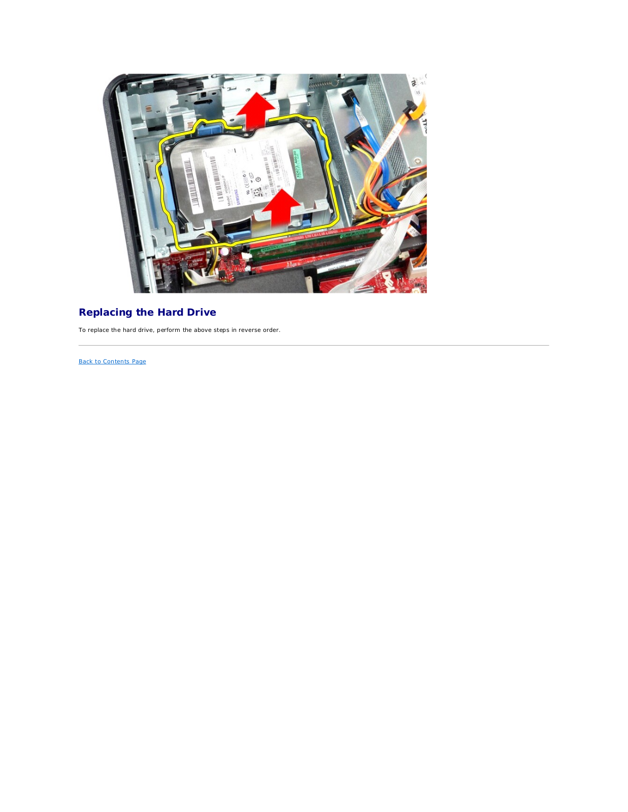
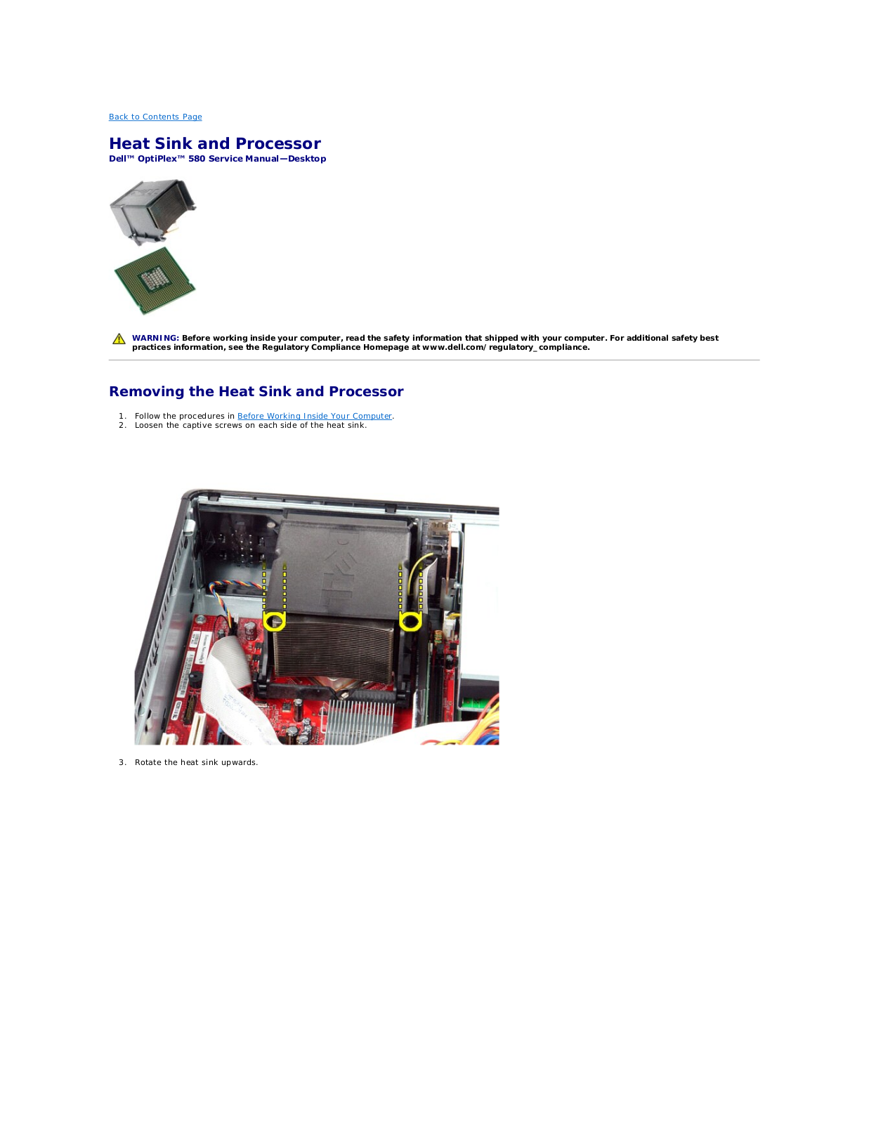
OptiPlex 580 Desktop
Service Manual
49 pgs
5.04 Mb
0
Service Manual [ar]
49 pgs
5.19 Mb
0
Service Manual [cs]
49 pgs
5.14 Mb
0
Service Manual [da]
49 pgs
5.06 Mb
0
Service Manual [de]
49 pgs
5.08 Mb
0
Service Manual [es]
49 pgs
5.08 Mb
0
Service Manual [fi]
49 pgs
5.08 Mb
0
Service Manual [fr]
49 pgs
5.09 Mb
0
Service Manual [gr]
49 pgs
5.12 Mb
0
Service Manual [he]
49 pgs
5.13 Mb
0
Service Manual [hr]
49 pgs
5.07 Mb
0
Service Manual [hu]
49 pgs
5.11 Mb
0
Service Manual [it]
49 pgs
5.07 Mb
0
Service Manual [ja]
49 pgs
5.35 Mb
0
Service Manual [ko]
49 pgs
5.24 Mb
0
Service Manual [nl]
49 pgs
5.06 Mb
0
Service Manual [no]
49 pgs
5.08 Mb
0
Service Manual [po]
49 pgs
5.12 Mb
0
Service Manual [pt]
49 pgs
5.09 Mb
0
Service Manual [pt]
49 pgs
5.09 Mb
0
Service Manual [ro]
49 pgs
5.11 Mb
0
Service Manual [sk]
49 pgs
5.13 Mb
0
Service Manual [sl]
49 pgs
5.08 Mb
0
Service Manual [sr]
49 pgs
5.1 Mb
0
Service Manual [sv]
49 pgs
5.08 Mb
0
Service Manual [tr]
49 pgs
5.14 Mb
0
Service Manual [zh]
49 pgs
5.57 Mb
0
Service Manual [zh]
49 pgs
5.34 Mb
0
Table of contents
Loading...
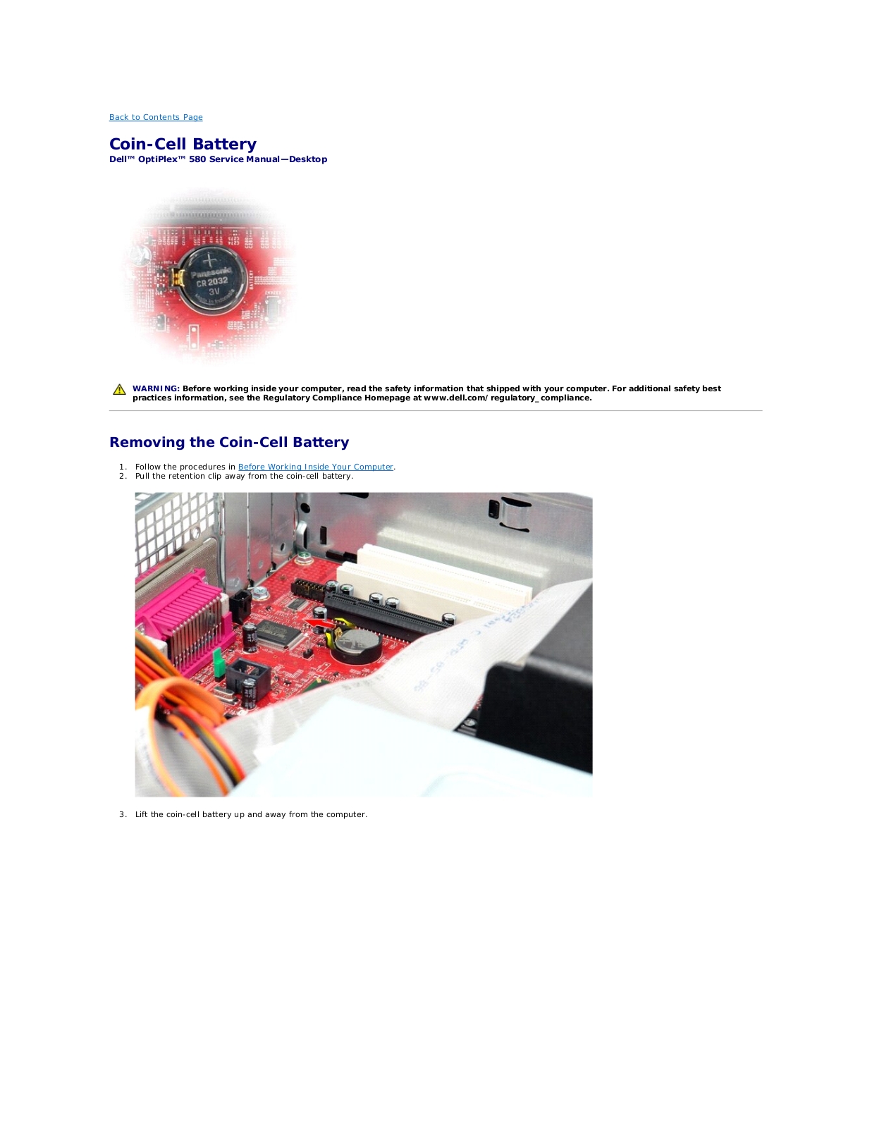
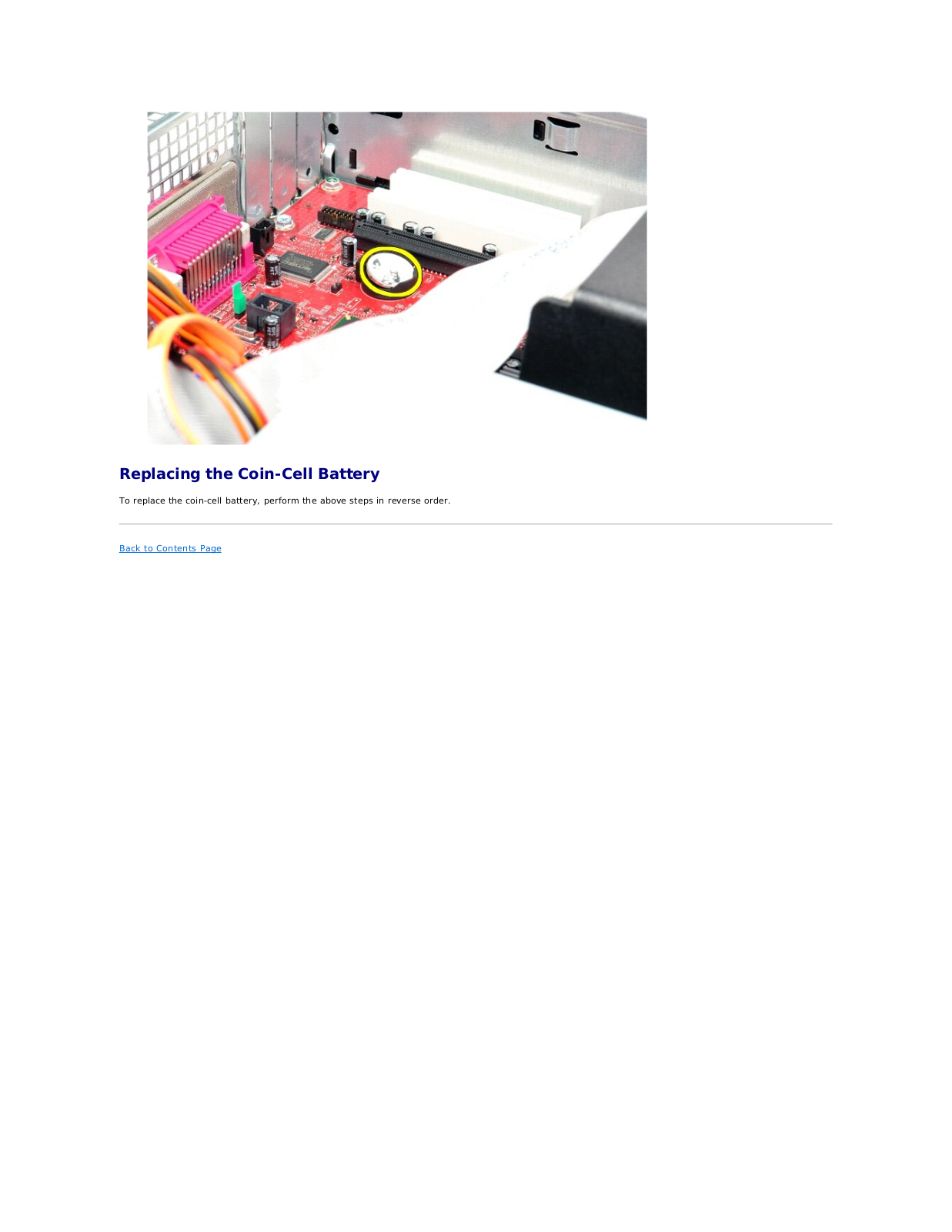
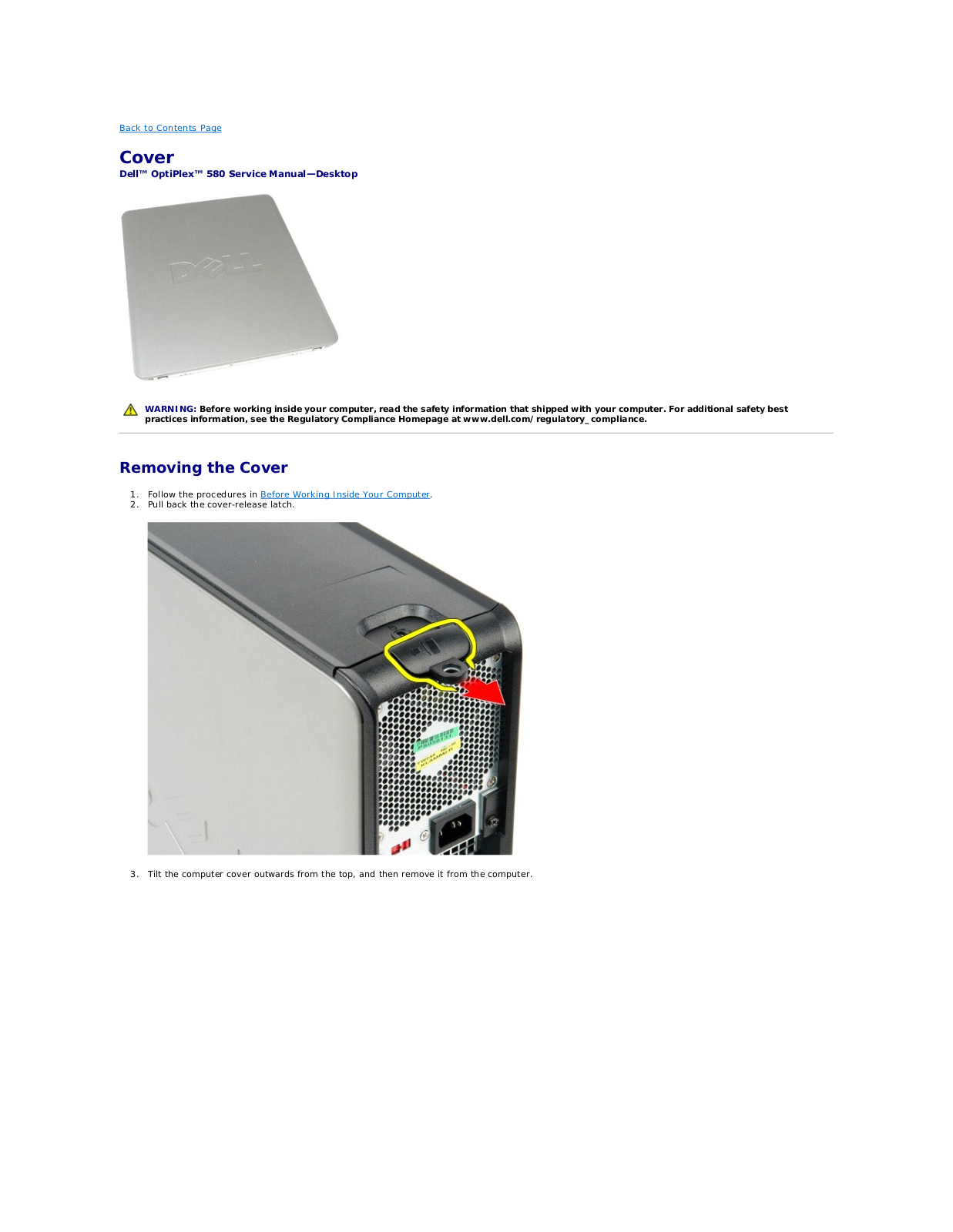
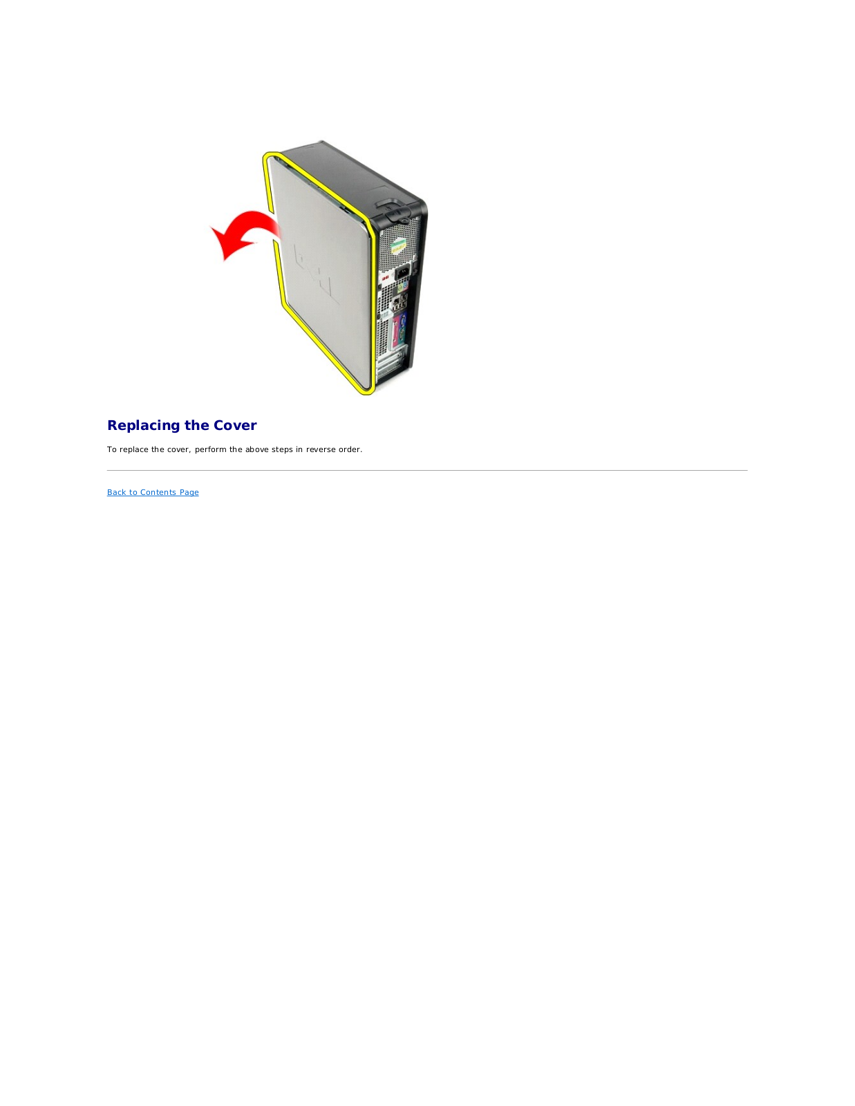
Dell OptiPlex 580 Desktop Service Manual
...
Dell Service Manual
Download
Specifications and Main Features
Frequently Asked Questions
User Manual
Download
Loading...
+
34
hidden pages
Unhide
You need points to download manuals.
1 point = 1 manual.
You can buy points or you can get point for every manual you upload.
Buy points
Upload your manuals
 Loading...