

Dell OptiPlex 5250 User Manual

Dell OptiPlex 5250 All-In-One
Owners Manual
Regulatory Model: W14B
Regulatory Type: W14B002

Identifier GUID-5B8DE7B7-879F-45A4-88E0-732155904029
Version 13
Status Released
Notes, cautions, and warnings
NOTE: A NOTE indicates important information that helps you make better use of your product.
CAUTION: A CAUTION indicates either potential damage to hardware or loss of data and tells you how to avoid the
problem.
WARNING: A WARNING indicates a potential for property damage, personal injury, or death.
© 2017 2020 Dell Inc. or its subsidiaries. All rights reserved. Dell, EMC, and other trademarks are trademarks of Dell Inc. or its
subsidiaries. Other trademarks may be trademarks of their respective owners.
May 2020
Rev. A04

Contents
1 Working on your computer.............................................................................................................7
Before working inside your computer................................................................................................................................. 7
Safety instructions.................................................................................................................................................................7
Recommended tools..............................................................................................................................................................8
Turning off your computer................................................................................................................................................... 8
Turning off your computer — Windows 7................................................................................................................... 8
Turning off your computer — Windows 10..................................................................................................................8
After working inside your computer....................................................................................................................................9
Important Information........................................................................................................................................................... 9
2 Removing and installing components............................................................................................ 10
Stand......................................................................................................................................................................................10
Removing the stand.......................................................................................................................................................10
Installing the stand......................................................................................................................................................... 12
Cable cover........................................................................................................................................................................... 12
Removing the cable cover.............................................................................................................................................12
Installing the cable cover............................................................................................................................................... 13
Back cover............................................................................................................................................................................ 13
Removing the back cover..............................................................................................................................................13
Installing the back cover................................................................................................................................................15
Speaker cover.......................................................................................................................................................................15
Removing the speaker cover........................................................................................................................................ 15
Installing the speaker cover...........................................................................................................................................16
Hard drive..............................................................................................................................................................................16
Removing the hard drive assembly.............................................................................................................................. 16
Installing the hard drive assembly.................................................................................................................................17
Optical drive..........................................................................................................................................................................18
Removing the optical drive assembly...........................................................................................................................18
Installing the optical drive assembly.............................................................................................................................19
System board shield.............................................................................................................................................................19
Removing the system board shield.............................................................................................................................. 19
Installing the system board shield................................................................................................................................20
Memory modules................................................................................................................................................................. 20
Removing the memory module....................................................................................................................................20
Installing the memory module....................................................................................................................................... 21
Solid State Drive — optional.............................................................................................................................................. 21
Removing the SSD card................................................................................................................................................ 21
Installing the SSD card..................................................................................................................................................22
Coin cell battery...................................................................................................................................................................23
Removing the coin cell battery.................................................................................................................................... 23
Installing the coin cell battery.......................................................................................................................................23
WLAN card...........................................................................................................................................................................24
Removing the WLAN card............................................................................................................................................24
Installing the WLAN card.............................................................................................................................................. 24
Contents 3

Heat sink...............................................................................................................................................................................25
Removing the heat sink ............................................................................................................................................... 25
Installing the heat sink...................................................................................................................................................25
Speaker.................................................................................................................................................................................26
Removing the speaker module.....................................................................................................................................26
Installing the speaker module....................................................................................................................................... 27
Display panel.........................................................................................................................................................................27
Removing the display panel.......................................................................................................................................... 27
Installing the display panel............................................................................................................................................ 29
Chassis frame.......................................................................................................................................................................29
Removing the chassis frame........................................................................................................................................ 29
Installing the chassis frame........................................................................................................................................... 31
Power supply unit................................................................................................................................................................ 32
Removing the Power Supply Unit - PSU....................................................................................................................32
Installing the Power Supply Unit - PSU...................................................................................................................... 34
VESA mount bracket...........................................................................................................................................................34
Removing the VESA mount bracket........................................................................................................................... 34
Installing the VESA mount bracket..............................................................................................................................35
Converter board.................................................................................................................................................................. 35
Removing the converter board....................................................................................................................................35
Installing the converter board...................................................................................................................................... 36
System fan............................................................................................................................................................................37
Removing the system fan.............................................................................................................................................37
Installing the system fan............................................................................................................................................... 38
Intrusion switch....................................................................................................................................................................38
Removing the intrusion switch.................................................................................................................................... 38
Installing the intrusion switch.......................................................................................................................................39
Power and On-Screen Display buttons board................................................................................................................. 40
Removing the power and On-Screen Display- OSD buttons board....................................................................... 40
Installing the power and OSD buttons board.............................................................................................................40
Processor.............................................................................................................................................................................. 41
Removing the processor................................................................................................................................................41
Installing the processor................................................................................................................................................. 42
System board....................................................................................................................................................................... 42
Removing the system board........................................................................................................................................ 42
Installing the system board...........................................................................................................................................45
System board layout......................................................................................................................................................46
3 M.2 Intel Optane Memory Module 16 GB....................................................................................... 47
Overview...............................................................................................................................................................................47
Intel®OptaneTM Memory Module Driver Requirements................................................................................................ 47
Installing M.2 Intel Optane Memory Module 16 GB.........................................................................................................47
Product specifications........................................................................................................................................................ 49
Environmental Conditions.................................................................................................................................................. 50
Troubleshooting...................................................................................................................................................................50
4 Technology and components....................................................................................................... 52
Storage options................................................................................................................................................................... 52
Identifying the hard drive in Windows 10....................................................................................................................53
4
Contents

Entering BIOS setup......................................................................................................................................................53
Memory configurations.......................................................................................................................................................53
Verifying system memory in Windows 10 and Windows 7 ...................................................................................... 53
DDR4.....................................................................................................................................................................................54
5 System setup.............................................................................................................................56
Boot Sequence.................................................................................................................................................................... 56
Navigation keys................................................................................................................................................................... 56
System setup options......................................................................................................................................................... 57
System setup options......................................................................................................................................................... 57
General screen options................................................................................................................................................. 57
System configuration screen options......................................................................................................................... 58
Security screen options................................................................................................................................................ 59
Secure boot screen options.......................................................................................................................................... 61
Intel Software Guard Extensions options....................................................................................................................61
Performance screen options........................................................................................................................................62
Power management screen options........................................................................................................................... 62
POST behavior screen options.................................................................................................................................... 63
Virtualization support screen options..........................................................................................................................64
Maintenance screen options........................................................................................................................................ 64
System Log screen options..........................................................................................................................................65
Updating the BIOS ............................................................................................................................................................. 65
Updating your system BIOS using a USB flash drive......................................................................................................65
System and setup password..............................................................................................................................................66
Assigning a system password and setup password.................................................................................................. 66
Deleting or changing an existing system and or setup password............................................................................67
6 Troubleshooting your computer...................................................................................................68
Enhanced Pre-Boot System Assessment — ePSA diagnostics................................................................................... 68
Running the ePSA diagnostics.....................................................................................................................................68
Diagnostics........................................................................................................................................................................... 68
Power supply-built in self test BIST..................................................................................................................................69
Power supply........................................................................................................................................................................70
LCD built in self test - BIST................................................................................................................................................70
7 Technical specifications.............................................................................................................. 73
Processors............................................................................................................................................................................73
Memory specifications........................................................................................................................................................ 74
Video specifications.............................................................................................................................................................74
Audio specifications.............................................................................................................................................................74
Communication specifications........................................................................................................................................... 75
Cards specifications............................................................................................................................................................ 75
Display specifications.......................................................................................................................................................... 75
Drives specifications............................................................................................................................................................75
Port and connector specifications.....................................................................................................................................76
Power specifications........................................................................................................................................................... 76
Camera specifications - optional....................................................................................................................................... 76
Stand specifications............................................................................................................................................................ 77
Physical specifications.........................................................................................................................................................77
Contents
5

Environmental specifications..............................................................................................................................................77
8 Contacting Dell.......................................................................................................................... 79
6 Contents

Identifier GUID-9CCD6D90-C1D1-427F-9E77-D4F83F3AD2B6
Version 3
Status Released
Working on your computer
Identifier GUID-CEF5001C-74CA-41CA-8C75-25E2A80E8909
Version 17
Status Released
Before working inside your computer
To avoid damaging your computer, perform the following steps before you begin working inside the computer.
1. Ensure that you follow the Safety instructions.
2. Ensure that your work surface is flat and clean to prevent the computer cover from being scratched.
3. Ensure you follow the Turning off your computer.
4. Disconnect all network cables from the computer.
CAUTION: To disconnect a network cable, first unplug the cable from your computer and then unplug the cable from
the network device.
5. Disconnect your computer and all attached devices from their electrical outlets.
6. Press and hold the power button while the computer is unplugged to ground the system board.
7. Remove the cover.
NOTE:
To avoid electrostatic discharge, ground yourself by using a wrist grounding strap or by periodically touching
an unpainted metal surface at the same time as touching a connector on the back of the computer.
1
Identifier GUID-9821EDD0-9810-4752-8B3C-AF89B67C2DB0
Version 5
Status Released
Safety instructions
Use the following safety guidelines to protect your computer from potential damage and to ensure your personal safety. Unless otherwise
noted, each procedure included in this document assumes that the following conditions exist:
• You have read the safety information that shipped with your computer.
• A component can be replaced or, if purchased separately, installed by performing the removal procedure in reverse order.
NOTE:
Disconnect all power sources before opening the computer cover or panels. After you finish working inside the
computer, replace all covers, panels, and screws before connecting to the power source.
NOTE: Before working inside your computer, read the safety information that shipped with your computer. For
additional safety best practices information, see the Regulatory Compliance Homepage at www.Dell.com/
regulatory_compliance
CAUTION: Many repairs may only be done by a certified service technician. You should only perform troubleshooting and
simple repairs as authorized in your product documentation, or as directed by the online or telephone service and
support team. Damage due to servicing that is not authorized by Dell is not covered by your warranty. Read and follow
the safety instructions that came with the product.
CAUTION: To avoid electrostatic discharge, ground yourself by using a wrist grounding strap or by periodically touching
an unpainted metal surface at the same time as touching a connector on the back of the computer.
CAUTION: Handle components and cards with care. Do not touch the components or contacts on a card. Hold a card by
its edges or by its metal mounting bracket. Hold a component such as a processor by its edges, not by its pins.
Working on your computer 7

CAUTION: When you disconnect a cable, pull on its connector or on its pull-tab, not on the cable itself. Some cables
have connectors with locking tabs; if you are disconnecting this type of cable, press in on the locking tabs before you
disconnect the cable. As you pull connectors apart, keep them evenly aligned to avoid bending any connector pins. Also,
before you connect a cable, ensure that both connectors are correctly oriented and aligned.
NOTE: The color of your computer and certain components may appear differently than shown in this document.
Identifier GUID-CC927E5A-E514-4067-B6FA-84EC064F85E9
Version 6
Status Released
Recommended tools
The procedures in this document require the following tools:
• Small flat blade screwdriver
• Phillips # 1 screwdriver
• Small plastic scribe
Identifier
Version 9
Status Released
GUID-52C8386F-7013-4A8E-912D-2DF589CA6CA4
Turning off your computer
Identifier
Version 1
Status Released
Turning off your computer — Windows 7
CAUTION:
computer.
1. Click Start.
2. Click Shut Down.
Identifier GUID-B70C8BD7-328C-424F-8DF4-80728A0080AB
Version 3
Status Released
To avoid losing data, save and close all open files and exit all open programs before you turn off your
NOTE:
Ensure that the computer and all attached devices are turned off. If your computer and attached devices did
not automatically turn off when you shut down your operating system, press and hold the power button for about 6
seconds to turn them off.
GUID-8CC3ED6C-E9FF-44B2-B71A-231B2D871043
Turning off your computer — Windows 10
CAUTION:
computer.
1. Click or tap .
2. Click or tap
8 Working on your computer
To avoid losing data, save and close all open files and exit all open programs before you turn off your
and then click or tap Shut down.
Ensure that the computer and all attached devices are turned off. If your computer and attached devices did
NOTE:
not automatically turn off when you shut down your operating system, press and hold the power button for about 6
seconds to turn them off.

Identifier GUID-F99E5E0D-8C96-4B55-A6C9-5722A035E20C
Version 8
Status Released
After working inside your computer
After you complete any replacement procedure, ensure that you connect any external devices, cards, and cables before turning on your
computer.
1. Replace the cover.
2. Connect any telephone or network cables to your computer.
CAUTION: To connect a network cable, first plug the cable into the network device and then plug it into the
computer.
3. Connect your computer and all attached devices to their electrical outlets.
4. Turn on your computer.
5. If required, verify that the computer works correctly by running ePSA diagnostics.
Identifier
Version 1
Status Released
GUID-75068AC1-4997-4728-8C15-2A9B138C7BFD
Important Information
NOTE: Avoid using the touchscreen in dusty, hot, or humid environments.
NOTE: Sudden change in temperature may cause condensation on the inner surface of the glass screen, which will
disappear after a short time and does not affect normal usage.
Working on your computer 9

Identifier GUID-7AAAE6E7-9D06-4C20-82BF-728ABC2DF3EF
Version 4
Status Released
Removing and installing components
Identifier GUID-8C1F5E66-1E60-4FCD-A91B-7CF35B61EE5F
Version 1
Status Released
Stand
2
Identifier
Version 7
Status Released
GUID-1ABD59E3-D701-481B-8D38-B295F96E5F20
Removing the stand
NOTE: The system is shipped with three different types of stands:
• Height Adjustable Stand
• Basic Stand
• Articulating Stand
The removal procedure is the same for all the three stands.
1. Follow the procedure in Before working inside your computer.
2. Place the computer on clean, flat surface with the display facing downward.
3. To remove the stand:
a) Press the tab on the cover to release the stand [1].
b) Lift the stand upward [2].
NOTE: Each of the three stands will attach and detach in the same manner.
10 Removing and installing components

Figure 1. Height Adjustable Stand
Figure 2. Fix stand
Removing and installing components
11
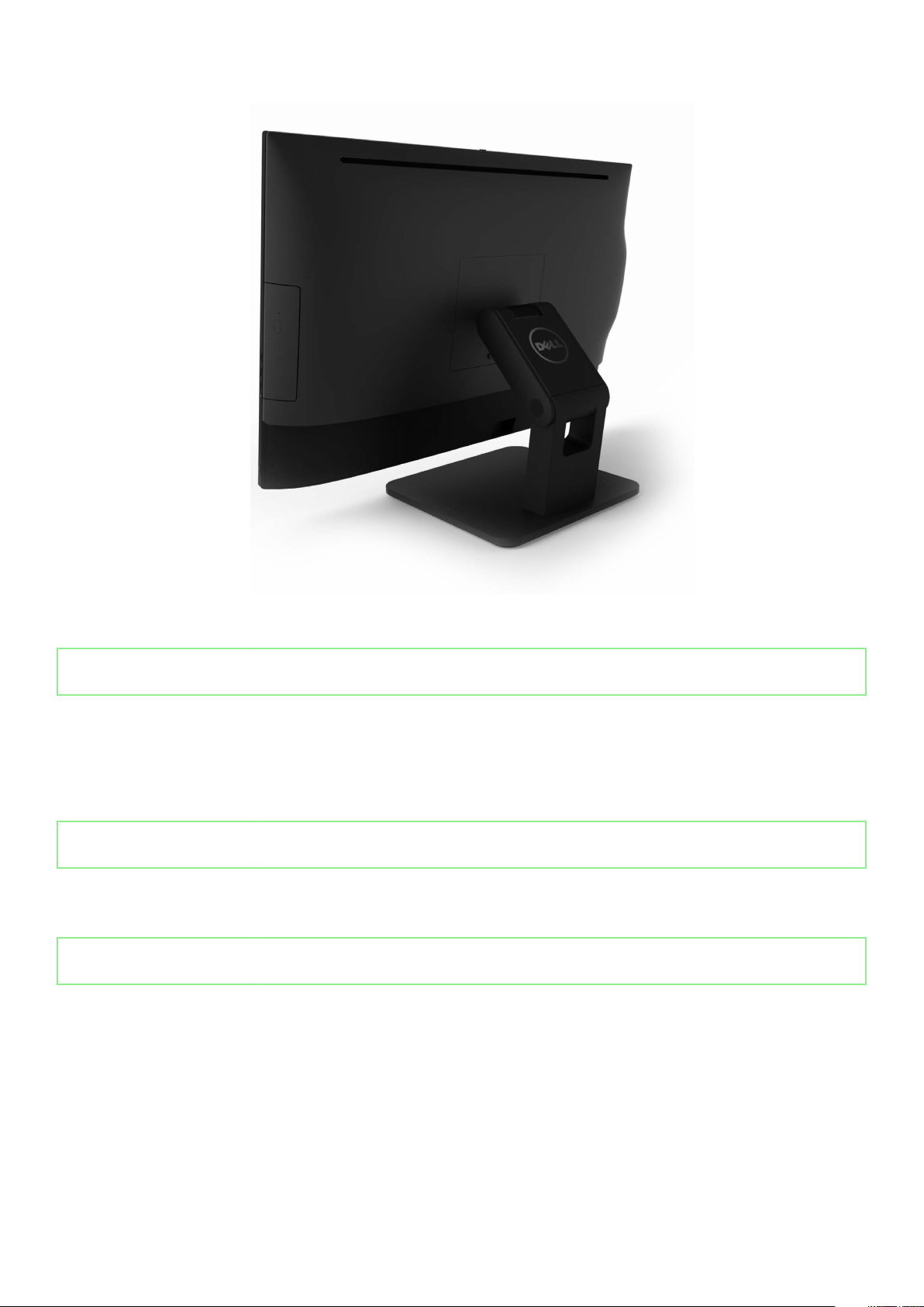
Figure 3. Articulate stand
Identifier
Version 3
Status Released
GUID-A82988C4-8726-4E6A-9D9F-0D0AC35CB32E
Installing the stand
1. Place the computer on a clean, flat surface and align the stand, and then slide it on the back of the computer.
2. Press the stand down till it snaps in.
3. Follow the procedure in After working inside your computer.
Identifier
Version 1
Status Released
GUID-56AEF6F7-F81F-4702-A5E9-C87C98D5BD4F
Cable cover
Identifier
Version 2
Status Released
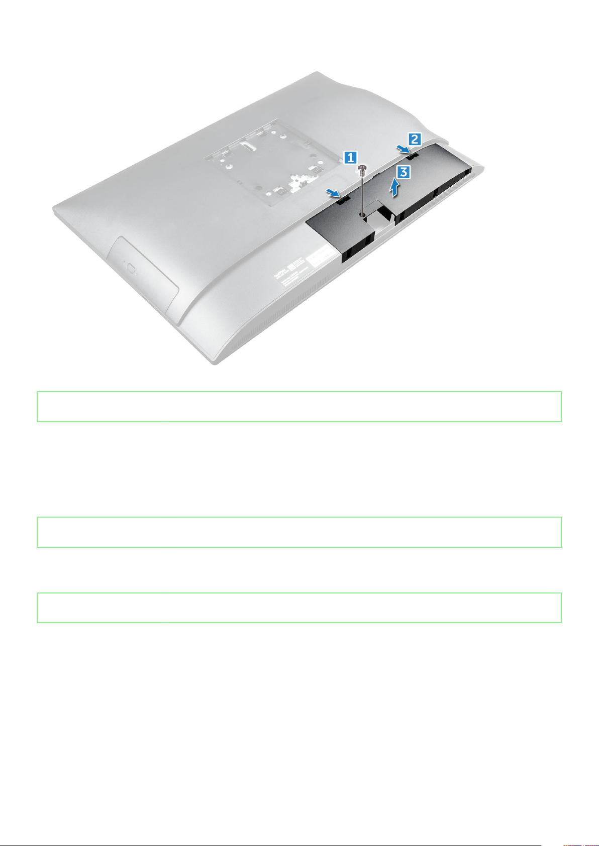
Removing the cable cover
1. Follow the procedure in Before working inside your computer.
2. Remove the stand.
3. To remove the cable cover:
a) Remove the screw that secures the cable cover to the computer [1].
b) Push the release tabs to release the cable cover [2].
c) Lift the cable cover away from the computer [3].
GUID-47FD06C0-86FC-4E37-B99C-C6EC44D873C5
12
Removing and installing components
Identifier GUID-2E1F1515-B7D9-4480-B827-707CAFF73E05
Version 3
Status Released
Installing the cable cover
1. Align the notches on the cable cover to the holes on the computer and press the cable cover until it snaps in.
2. Tighten the screw to secure the cable cover to the computer.
3. Install the stand.
4. Follow the procedure in After working inside your computer.
Identifier
Version 1
Status Released
GUID-DB05E4C2-3322-4EDA-B0A7-196A94EB33C7
Back cover
Identifier
Version 2
Status Released
Removing the back cover
1. Follow the procedure in Before working inside your computer.
2. Remove the:
a) stand
b) cable cover
3. Pry the edges of the back cover from the bottom to release it from the computer.
GUID-FBCB15C9-48C1-4036-BF6B-79DA40173C7D
Removing and installing components
13
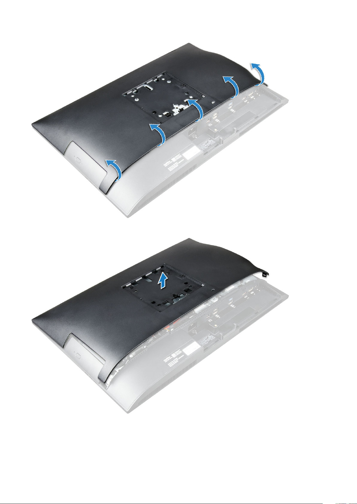
4. Lift the back cover from the computer.
14
Removing and installing components

Identifier GUID-3A81F973-49B2-48C7-BC06-F72586B2190F
Version 3
Status Released
Installing the back cover
1. Align the notches on the back cover to the holes on the computer, and press the back cover until it snaps in.
2. Install the:
a) cable cover
b) stand
3. Follow the procedure in After working inside your computer.
Identifier GUID-6957AFB9-31CC-4F48-82F7-BC214091C9FF
Version 1
Status Released
Speaker cover
Identifier
Version 3
Status Released
GUID-4F173EC7-6549-4C9E-AD95-9B8F5039A957
Removing the speaker cover
1. Follow the procedure in Before working inside your computer.
2. Remove the:
a) stand
b) cable cover
c) back cover
3. Remove the screws that secure the speaker cover to the computer.
4. Pull and remove the speaker cover from the computer.
NOTE: To avoid damage to the back cover, release it from the pull tabs.
Removing and installing components 15
Identifier GUID-2359918A-F262-4C2D-BF8D-24C018033579
Version 4
Status Released
Installing the speaker cover
1. Align and push the speaker cover to pop tabs into its position on the back of the computer.
2. Tighten the screws to secure the speaker cover to the computer.
3. Install the:
a) back cover
b) cable cover
c) stand
4. Follow the procedure in After Working Inside Your Computer.
Identifier
Version 1
Status Released
GUID-DA236FEA-AA29-400C-89C3-C25D4B9DE6F3
Hard drive
Identifier
Version 3
Status Released
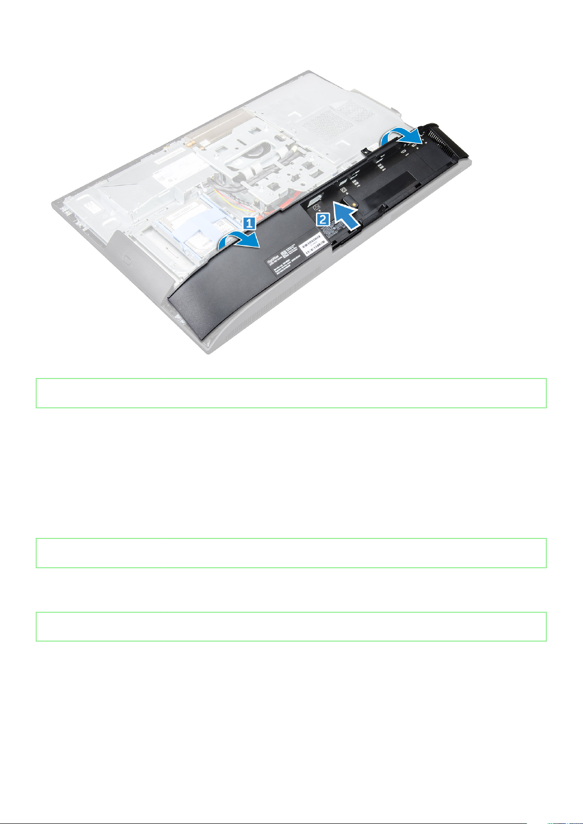
Removing the hard drive assembly
1. Follow the procedure in Before working inside your computer.
2. Remove the:
a) stand
b) back cover
3. To remove the hard drive assembly:
a) Press the tab on the bracket, and slide the hard-drive assembly until the tabs are released from either side of the assembly [1].
16
Removing and installing components
GUID-28DE9945-2701-465C-A538-8C584A7A2528
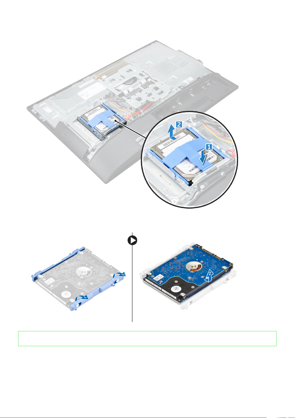
b) Slide the hard-drive assembly upwards to remove it from the computer [2].
4. To remove the hard drive bracket:
a) Pry the edges of the bracket to release the hard drive [1].
b) Slide the hard drive and lift it away from the bracket [2].
Identifier
Version 4
Status Released
GUID-F8E0D7DF-28C1-49ED-A797-8C0F4D632585
Installing the hard drive assembly
1. Align the hard drive until the notches are aligned and the hard drive is secured in the bracket.
2. Place the hard drive onto the hard drive cage until the notches are aligned, then slide the Hard Drive assembly until the tab locks into
the cage.
Removing and installing components
17
3. Install the:
a) back cover
b) stand
4. Follow the procedure in After working inside your computer.
Identifier GUID-78527CE0-7E4A-4B32-A077-A2DAA34B0418
Version 1
Status Released
Optical drive
Identifier GUID-73CE457C-A1CD-40DA-BDB7-187EEA0E2CC9
Version 2
Status Released
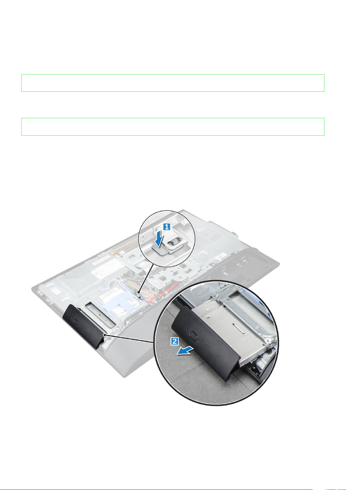
Removing the optical drive assembly
1. Follow the procedure in Before working inside your computer.
2. Remove the:
a) stand
b) back cover
3. To remove the optical drive assembly:
a) Press the securing tab at the base of the drive to release the optical drive assembly [1].
b) Slide the optical drive assembly to remove it away from the computer [2].
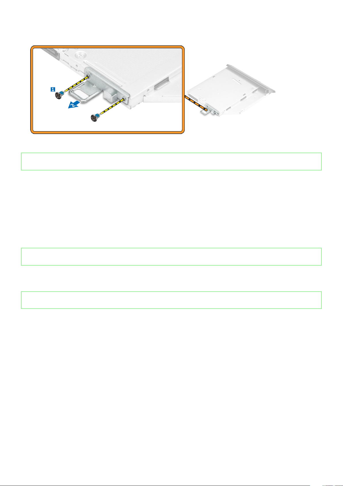
4. To remove the optical drive bracket:
a) Remove the screws that secure the optical drive bracket [1].
b) Remove the bracket away from the optical drive [2].
18
Removing and installing components
Identifier GUID-52C81C40-7D4B-48C8-95CD-011AB917E2CA
Version 2
Status Released
Installing the optical drive assembly
1. Place the bracket to align the screw holders on the optical drive.
2. Tighten the screws to secure the bracket to the optical drive.
3. Insert the optical drive assembly into the drive slot, until it snaps in.
4. Install the:
a) back cover
b) stand
5. Follow the procedure in After working inside your computer.
Identifier
Version 1
Status Released
GUID-33DB4570-1B11-40E9-9382-360DA839B91A
System board shield
Identifier
Version 2
Status Released
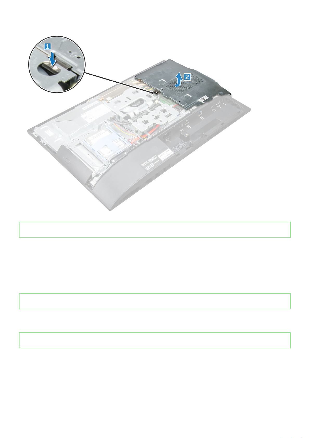
Removing the system board shield
1. Follow the procedure in Before working inside your computer.
2. Remove the:
a) stand
b) back cover
3. To remove the system board shield:
a) Press the securing tab to release the system board shield from the slots on the computer [1].
b) Slide the system board shield away from the computer [2].
GUID-63DB88A1-D144-428B-9466-BDC3C7ACCA1A
Removing and installing components
19
Identifier GUID-C05DE44D-1BAF-4F65-865B-7E056E267EB2
Version 2
Status Released
Installing the system board shield
1. Align and slide the system board shield until it snaps in.
2. Install the:
a) back cover
b) stand
3. Follow the procedure in After working inside your computer.
Identifier
Version 2
Status Released
GUID-B4BFAFB3-4A6A-47FD-A777-9CA7EF95C20B
Memory modules
Identifier
Version 2
Status Released
Removing the memory module
1. Follow the procedure in Before working inside your computer.
2. Remove the:
a) stand
b) back cover
c) system board shield
20
Removing and installing components
GUID-25F1E2CA-FA5B-4883-911B-9A305DBA0195

3. To remove the memory module:
a) Pry the retention clips away from the memory module until it pops up [1].
b) Lift the memory module from the connector [2].
Identifier GUID-B6441BB3-C3B6-4362-8311-3A49B2E14D77
Version 3
Status Released
Installing the memory module
1. Insert the memory module on the memory connector until the clips secure the memory module.
2. Install the:
a) system board shield
b) back cover
c) stand
3. Follow the procedure in After working inside your computer.
Identifier
Version 3
Status Released
GUID-BD5DA6BF-1EAB-4EAE-8294-A1AEE6C1C907
Solid State Drive — optional
Identifier
Version 1
Status Released
Removing the SSD card
1. Follow the procedure in Before working inside your computer.
2. Remove the:
GUID-A78C6DBC-6B92-4FB5-AF47-B2ACDB544847
Removing and installing components
21
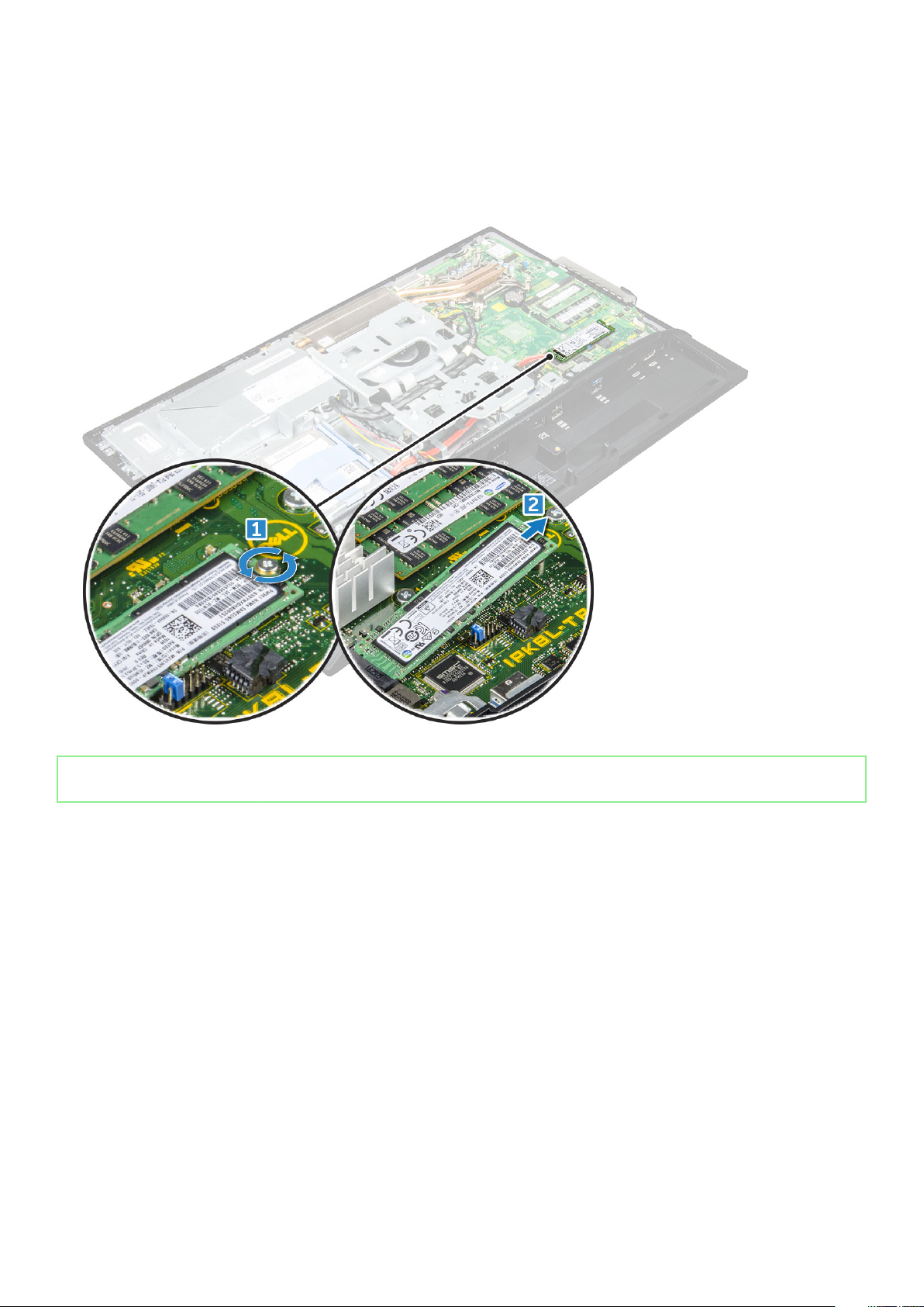
a) stand
b) back cover
c) system board shield
3. To remove the SSD card:
a) Remove the screw that secures the SSD card to the computer [1].
b) Lift the SSD card away from the connector [2].
Identifier GUID-ACEA12E1-6B7F-4578-A477-434D9B5ED241
Version 1
Status Released
Installing the SSD card
1. Insert the SSD card into the connector.
2. Tighten the screw to secure the SSD card to the system board.
3. Install the:
a) system board shield
b) back cover
c) stand
4. Follow the procedure in After working inside your computer.
22
Removing and installing components
Identifier GUID-B369D04D-3080-4AE8-912A-8F95B80E032D
Version 2
Status Released
Coin cell battery
Identifier GUID-CF7165BA-8419-4F14-8CC8-351AEF21562E
Version 2
Status Released
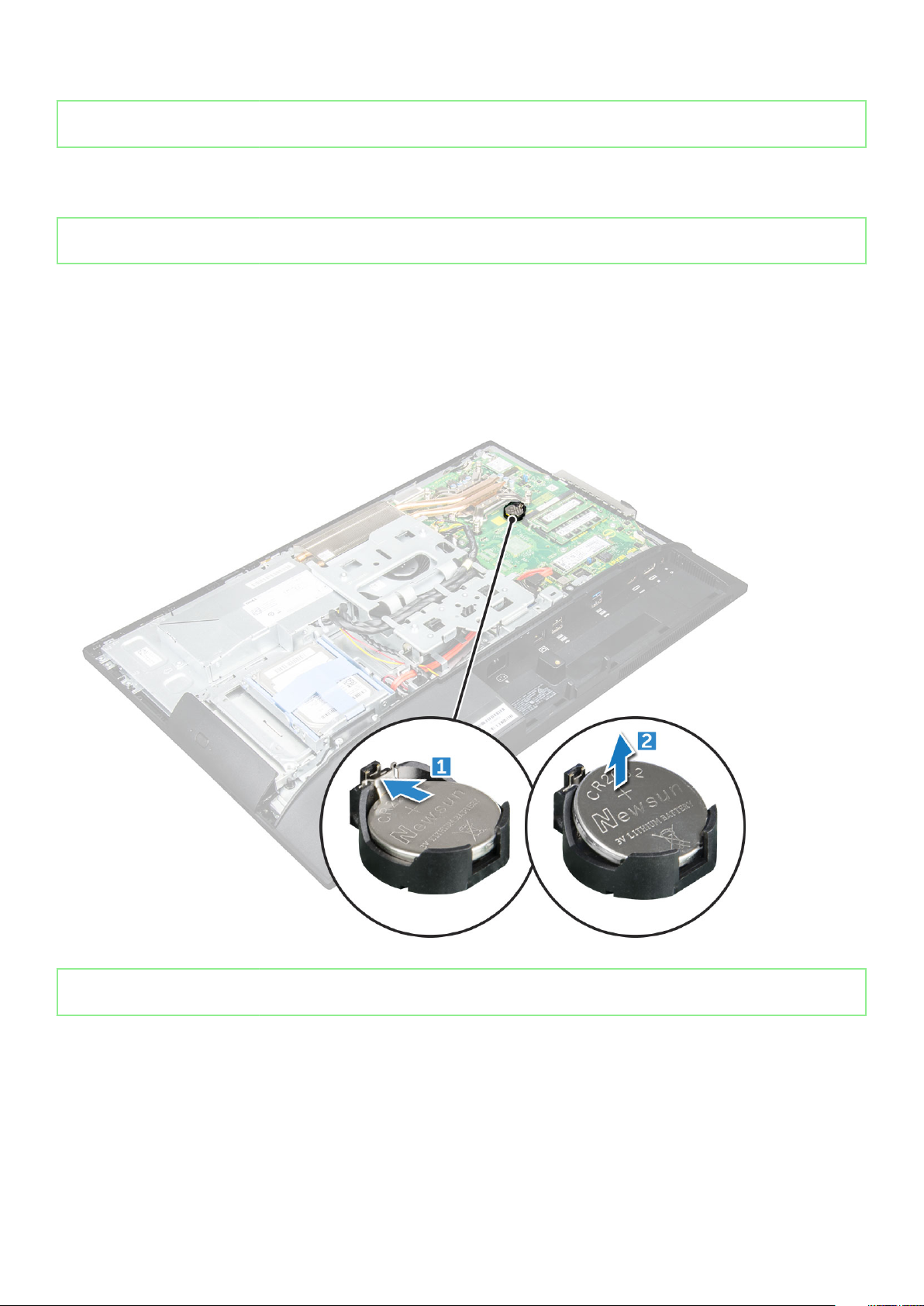
Removing the coin cell battery
1. Follow the procedure in Before working inside your computer.
2. Remove the:
a) stand
b) back cover
c) system board shield
3. Press the latch to release the coin cell battery and remove it from the computer.
Identifier
Version 2
Status Released
GUID-ABA261B2-0286-439D-998E-9E9737666AD9
Installing the coin cell battery
1. Insert the coin cell battery into the slot on the system board until it fits securely.
2. Install the:
a) system board shield
b) back cover
c) stand
3. Follow the procedure in After working inside your computer.
Removing and installing components
23

Identifier GUID-CCAA203F-6E60-4861-BC9C-1EED5672FD0D
Version 1
Status Released
WLAN card
Identifier GUID-512DE943-51D2-4CE2-AA39-E2984B812C69
Version 2
Status Released
Removing the WLAN card
1. Follow the procedure in Before working inside your computer.
2. Remove the:
a) stand
b) back cover
c) system board shield
3. To remove the WLAN card:
a) Disconnect the antenna cables from the connectors on the WLAN card [1].
b) Remove the screw that secures the WLAN card to the system board [2].
c) Hold the WLAN card and pull it from the connector on the system board [3].
Identifier
Version 2
Status Released
GUID-B106BFA3-360B-42A7-A6E8-21450A351A9F
Installing the WLAN card
1. Align the WLAN card to the connector on the system board.
2. Tighten the screw to secure the WLAN card to the system board.
3. Connect the antenna cables to the connectors on the WLAN card.
4. Install the:
a) system board shield
24
Removing and installing components
 Loading...