

Page 1

OptiPlex 5070 Tower
Service Manual
Regulatory Model: D18M
Regulatory Type: D18M005
Page 2

Notes, cautions, and warnings
NOTE: A NOTE indicates important information that helps you make better use of your product.
CAUTION: A CAUTION indicates either potential damage to hardware or loss of data and tells you how to avoid the
problem.
WARNING: A WARNING indicates a potential for property damage, personal injury, or death.
© 2018 - 2019 Dell Inc. or its subsidiaries. All rights reserved. Dell, EMC, and other trademarks are trademarks of Dell Inc. or its
subsidiaries. Other trademarks may be trademarks of their respective owners.
2020 - 03
Rev. A00
Page 3

Contents
1 Working on your computer.............................................................................................................7
Safety instructions.................................................................................................................................................................7
Before working inside your computer............................................................................................................................7
Safety precautions...........................................................................................................................................................8
Electrostatic discharge—ESD protection.................................................................................................................... 8
ESD field service kit ........................................................................................................................................................9
Transporting sensitive components.............................................................................................................................. 9
After working inside your computer.............................................................................................................................10
2 Technology and components........................................................................................................ 11
DDR4...................................................................................................................................................................................... 11
USB features.........................................................................................................................................................................12
USB Type-C..........................................................................................................................................................................14
Advantages of DisplayPort over USB Type-C..................................................................................................................14
HDMI 2.0............................................................................................................................................................................... 15
Intel Optane memory........................................................................................................................................................... 15
Enabling Intel Optane memory......................................................................................................................................16
Disabling Intel Optane memory.....................................................................................................................................16
3 Major components of your system ............................................................................................... 17
4 Removing and installing components............................................................................................ 19
Side cover............................................................................................................................................................................. 19
Removing side cover......................................................................................................................................................19
Installing side cover........................................................................................................................................................ 19
Bezel......................................................................................................................................................................................20
Removing front bezel....................................................................................................................................................20
Installing front bezel....................................................................................................................................................... 21
Front panel door.................................................................................................................................................................. 22
Opening front panel door..............................................................................................................................................22
Closing front panel door................................................................................................................................................23
Hard drive assembly—3.5-inch and 2.5-inch.................................................................................................................. 24
Removing 3.5–inch hard drive assembly....................................................................................................................24
Removing 3.5–inch hard drive from the hard drive bracket....................................................................................25
Installing the 3.5–inch hard drive into the hard drive bracket.................................................................................26
Installing 3.5–inch hard drive assembly...................................................................................................................... 26
Removing the 2.5–inch hard drive assembly.............................................................................................................28
Removing the 2.5–inch drive from the drive bracket...............................................................................................28
Installing the 2.5–inch hard drive into the hard drive bracket.................................................................................29
Installing the 2.5-inch drive assembly......................................................................................................................... 29
Optical drive......................................................................................................................................................................... 30
Removing optical drive..................................................................................................................................................30
Installing optical drive.................................................................................................................................................... 32
M.2 PCIe SSD ..................................................................................................................................................................... 34
Contents 3
Page 4

Removing M.2 SSD ...................................................................................................................................................... 34
Installing M.2 SSD..........................................................................................................................................................35
SD card reader.....................................................................................................................................................................36
Removing SD card reader.............................................................................................................................................36
Installing SD card reader............................................................................................................................................... 37
Memory module...................................................................................................................................................................38
Removing memory module...........................................................................................................................................38
Installing memory module............................................................................................................................................. 39
Expansion card.....................................................................................................................................................................40
Removing PCIe expansion card................................................................................................................................... 40
Installing PCIe expansion card...................................................................................................................................... 41
Optional VGA module..........................................................................................................................................................42
Removing optional VGA module.................................................................................................................................. 42
Installing optional VGA module.....................................................................................................................................43
Power supply unit................................................................................................................................................................ 44
Removing power supply unit or PSU.......................................................................................................................... 44
Installing power supply unit or PSU.............................................................................................................................46
Intrusion switch....................................................................................................................................................................48
Removing intrusion switch........................................................................................................................................... 48
Installing intrusion switch..............................................................................................................................................49
Power button.......................................................................................................................................................................50
Removing power button...............................................................................................................................................50
Installing power button................................................................................................................................................. 52
Speaker.................................................................................................................................................................................54
Removing speaker......................................................................................................................................................... 54
Installing speaker........................................................................................................................................................... 55
Coin cell battery...................................................................................................................................................................56
Removing coin cell battery...........................................................................................................................................56
Installing the coin cell battery.......................................................................................................................................57
Heat sink fan........................................................................................................................................................................ 58
Removing heat sink fan................................................................................................................................................ 58
Installing heatsink fan....................................................................................................................................................59
Heat sink ..............................................................................................................................................................................60
Removing heatsink assembly....................................................................................................................................... 60
Installing heatsink assembly.......................................................................................................................................... 61
Processor..............................................................................................................................................................................62
Removing processor......................................................................................................................................................62
Installing processor........................................................................................................................................................63
System fan........................................................................................................................................................................... 64
Removing system fan....................................................................................................................................................64
Installing system fan......................................................................................................................................................66
System board.......................................................................................................................................................................68
Removing system board............................................................................................................................................... 68
Front panel door................................................................................................................................................................... 71
Opening front panel door...............................................................................................................................................71
Closing front panel door.................................................................................................................................................71
3.5-inch hard drive ............................................................................................................................................................. 72
Removing 3.5–inch hard drive assembly.................................................................................................................... 72
Installing 3.5–inch hard drive assembly...................................................................................................................... 73
3.5-inch hard drive........................................................................................................................................................ 75
4
Contents
Page 5

2.5-inch hard drive assembly ............................................................................................................................................ 76
Removing the 2.5–inch hard drive assembly............................................................................................................. 76
Installing the 2.5-inch drive assembly......................................................................................................................... 76
2.5-inch hard drive.........................................................................................................................................................77
Optical drive......................................................................................................................................................................... 78
Removing optical drive..................................................................................................................................................78
Installing optical drive....................................................................................................................................................80
M.2 SSD ...............................................................................................................................................................................82
Removing M.2 SSD ...................................................................................................................................................... 82
Installing M.2 SSD..........................................................................................................................................................83
SD card reader.....................................................................................................................................................................84
Removing SD card reader.............................................................................................................................................84
Installing SD card reader...............................................................................................................................................85
Memory module...................................................................................................................................................................86
Removing memory module...........................................................................................................................................86
Installing memory module............................................................................................................................................. 87
Expansion card.....................................................................................................................................................................88
Removing PCIe expansion card................................................................................................................................... 88
Installing PCIe expansion card......................................................................................................................................89
Power supply unit................................................................................................................................................................90
Removing power supply unit or PSU.......................................................................................................................... 90
Installing power supply unit or PSU.............................................................................................................................92
Intrusion switch....................................................................................................................................................................94
Removing intrusion switch........................................................................................................................................... 94
Installing intrusion switch..............................................................................................................................................95
Power button.......................................................................................................................................................................96
Removing power button...............................................................................................................................................96
Installing power button................................................................................................................................................. 98
Speaker............................................................................................................................................................................... 100
Removing speaker........................................................................................................................................................100
Installing speaker...........................................................................................................................................................101
Coin cell battery................................................................................................................................................................. 102
Removing coin cell battery..........................................................................................................................................102
Installing the coin cell battery..................................................................................................................................... 103
Heat sink fan.......................................................................................................................................................................104
Removing heat sink fan...............................................................................................................................................104
Installing heatsink fan.................................................................................................................................................. 105
Heatsink assembly............................................................................................................................................................. 106
Removing heatsink assembly......................................................................................................................................106
Installing heatsink assembly........................................................................................................................................ 107
Processor............................................................................................................................................................................ 108
Removing processor.................................................................................................................................................... 108
Installing processor...................................................................................................................................................... 109
System fan...........................................................................................................................................................................110
Removing system fan...................................................................................................................................................110
Installing system fan...................................................................................................................................................... 111
Optional VGA module......................................................................................................................................................... 112
Removing optional VGA module..................................................................................................................................112
Installing optional VGA module....................................................................................................................................113
System board...................................................................................................................................................................... 114
Contents
5
Page 6

Removing system board...............................................................................................................................................114
Installing the system board.......................................................................................................................................... 117
5 Troubleshooting........................................................................................................................120
Enhanced Pre-Boot System Assessment — ePSA diagnostics..................................................................................120
Running the ePSA Diagnostics...................................................................................................................................120
Diagnostics..........................................................................................................................................................................120
Diagnostic error messages................................................................................................................................................122
System error messages.....................................................................................................................................................125
6 Getting help............................................................................................................................. 126
Contacting Dell...................................................................................................................................................................126
6 Contents
Page 7

Working on your computer
Safety instructions
Use the following safety guidelines to protect your computer from potential damage and to ensure your personal safety. Unless otherwise
noted, each procedure included in this document assumes that the following conditions exist:
• You have read the safety information that shipped with your computer.
• A component can be replaced or, if purchased separately, installed by performing the removal procedure in reverse order.
NOTE: Disconnect all power sources before opening the computer cover or panels. After you finish working inside the
computer, replace all covers, panels, and screws before connecting to the power source.
WARNING: Before working inside your computer, read the safety information that shipped with your computer. For
additional safety best practices information, see the Regulatory Compliance Homepage
CAUTION: Many repairs may only be done by a certified service technician. You should only perform troubleshooting and
simple repairs as authorized in your product documentation, or as directed by the online or telephone service and
support team. Damage due to servicing that is not authorized by Dell is not covered by your warranty. Read and follow
the safety instructions that came with the product.
CAUTION: To avoid electrostatic discharge, ground yourself by using a wrist grounding strap or by periodically touching
an unpainted metal surface at the same time as touching a connector on the back of the computer.
1
CAUTION: Handle components and cards with care. Do not touch the components or contacts on a card. Hold a card by
its edges or by its metal mounting bracket. Hold a component such as a processor by its edges, not by its pins.
CAUTION: When you disconnect a cable, pull on its connector or on its pull-tab, not on the cable itself. Some cables
have connectors with locking tabs; if you are disconnecting this type of cable, press in on the locking tabs before you
disconnect the cable. As you pull connectors apart, keep them evenly aligned to avoid bending any connector pins. Also,
before you connect a cable, ensure that both connectors are correctly oriented and aligned.
NOTE: The color of your computer and certain components may appear differently than shown in this document.
Before working inside your computer
To avoid damaging your computer, perform the following steps before you begin working inside the computer.
1. Ensure that you follow the Safety Instruction.
2. Ensure that your work surface is flat and clean to prevent the computer cover from being scratched.
3. Turn off your computer.
4. Disconnect all network cables from the computer.
CAUTION:
the network device.
5. Disconnect your computer and all attached devices from their electrical outlets.
6. Press and hold the power button while the computer is unplugged to ground the system board.
NOTE:
an unpainted metal surface at the same time as touching a connector on the back of the computer.
To disconnect a network cable, first unplug the cable from your computer and then unplug the cable from
To avoid electrostatic discharge, ground yourself by using a wrist grounding strap or by periodically touching
Working on your computer 7
Page 8

Safety precautions
The safety precautions chapter details the primary steps to be taken before performing any disassembly instructions.
Observe the following safety precautions before you perform any installation or break/fix procedures involving disassembly or reassembly:
• Turn off the system and all attached peripherals.
• Disconnect the system and all attached peripherals from AC power.
• Disconnect all network cables, telephone, and telecommunications lines from the system.
• Use an ESD field service kit when working inside any to avoid electrostatic discharge (ESD) damage.
• After removing any system component, carefully place the removed component on an anti-static mat.
• Wear shoes with non-conductive rubber soles to reduce the chance of getting electrocuted.
Standby power
Dell products with standby power must be unplugged before you open the case. Systems that incorporate standby power are essentially
powered while turned off. The internal power enables the system to be remotely turned on (wake on LAN) and suspended into a sleep
mode and has other advanced power management features.
Unplugging, pressing and holding the power button for 15 seconds should discharge residual power in the system board.
Bonding
Bonding is a method for connecting two or more grounding conductors to the same electrical potential. This is done through the use of a
field service electrostatic discharge (ESD) kit. When connecting a bonding wire, ensure that it is connected to bare metal and never to a
painted or non-metal surface. The wrist strap should be secure and in full contact with your skin, and ensure that you remove all jewelry
such as watches, bracelets, or rings prior to bonding yourself and the equipment.
Electrostatic discharge—ESD protection
ESD is a major concern when you handle electronic components, especially sensitive components such as expansion cards, processors,
memory DIMMs, and system boards. Very slight charges can damage circuits in ways that may not be obvious, such as intermittent
problems or a shortened product life span. As the industry pushes for lower power requirements and increased density, ESD protection is
an increasing concern.
Due to the increased density of semiconductors used in recent Dell products, the sensitivity to static damage is now higher than in
previous Dell products. For this reason, some previously approved methods of handling parts are no longer applicable.
Two recognized types of ESD damage are catastrophic and intermittent failures.
• Catastrophic – Catastrophic failures represent approximately 20 percent of ESD-related failures. The damage causes an immediate
and complete loss of device functionality. An example of catastrophic failure is a memory DIMM that has received a static shock and
immediately generates a "No POST/No Video" symptom with a beep code emitted for missing or nonfunctional memory.
• Intermittent – Intermittent failures represent approximately 80 percent of ESD-related failures. The high rate of intermittent failures
means that most of the time when damage occurs, it is not immediately recognizable. The DIMM receives a static shock, but the
tracing is merely weakened and does not immediately produce outward symptoms related to the damage. The weakened trace may
take weeks or months to melt, and in the meantime may cause degradation of memory integrity, intermittent memory errors, etc.
The more difficult type of damage to recognize and troubleshoot is the intermittent (also called latent or "walking wounded") failure.
Perform the following steps to prevent ESD damage:
• Use a wired ESD wrist strap that is properly grounded. The use of wireless anti-static straps is no longer allowed; they do not provide
adequate protection. Touching the chassis before handling parts does not ensure adequate ESD protection on parts with increased
sensitivity to ESD damage.
• Handle all static-sensitive components in a static-safe area. If possible, use anti-static floor pads and workbench pads.
• When unpacking a static-sensitive component from its shipping carton, do not remove the component from the anti-static packing
material until you are ready to install the component. Before unwrapping the anti-static packaging, ensure that you discharge static
electricity from your body.
• Before transporting a static-sensitive component, place it in an anti-static container or packaging.
8
Working on your computer
Page 9

ESD field service kit
The unmonitored Field Service kit is the most commonly used service kit. Each Field Service kit includes three main components: antistatic mat, wrist strap, and bonding wire.
Components of an ESD field service kit
The components of an ESD field service kit are:
• Anti-Static Mat – The anti-static mat is dissipative and parts can be placed on it during service procedures. When using an antistatic mat, your wrist strap should be snug and the bonding wire should be connected to the mat and to any bare metal on the system
being worked on. Once deployed properly, service parts can be removed from the ESD bag and placed directly on the mat. ESDsensitive items are safe in your hand, on the ESD mat, in the system, or inside a bag.
• Wrist Strap and Bonding Wire – The wrist strap and bonding wire can be either directly connected between your wrist and bare
metal on the hardware if the ESD mat is not required, or connected to the anti-static mat to protect hardware that is temporarily
placed on the mat. The physical connection of the wrist strap and bonding wire between your skin, the ESD mat, and the hardware is
known as bonding. Use only Field Service kits with a wrist strap, mat, and bonding wire. Never use wireless wrist straps. Always be
aware that the internal wires of a wrist strap are prone to damage from normal wear and tear, and must be checked regularly with a
wrist strap tester in order to avoid accidental ESD hardware damage. It is recommended to test the wrist strap and bonding wire at
least once per week.
• ESD Wrist Strap Tester – The wires inside of an ESD strap are prone to damage over time. When using an unmonitored kit, it is a
best practice to regularly test the strap prior to each service call, and at a minimum, test once per week. A wrist strap tester is the
best method for doing this test. If you do not have your own wrist strap tester, check with your regional office to find out if they have
one. To perform the test, plug the wrist-strap's bonding-wire into the tester while it is strapped to your wrist and push the button to
test. A green LED is lit if the test is successful; a red LED is lit and an alarm sounds if the test fails.
• Insulator Elements – It is critical to keep ESD sensitive devices, such as plastic heat sink casings, away from internal parts that are
insulators and often highly charged.
• Working Environment – Before deploying the ESD Field Service kit, assess the situation at the customer location. For example,
deploying the kit for a server environment is different than for a desktop or portable environment. Servers are typically installed in a
rack within a data center; desktops or portables are typically placed on office desks or cubicles. Always look for a large open flat work
area that is free of clutter and large enough to deploy the ESD kit with additional space to accommodate the type of system that is
being repaired. The workspace should also be free of insulators that can cause an ESD event. On the work area, insulators such as
Styrofoam and other plastics should always be moved at least 12 inches or 30 centimeters away from sensitive parts before physically
handling any hardware components
• ESD Packaging – All ESD-sensitive devices must be shipped and received in static-safe packaging. Metal, static-shielded bags are
preferred. However, you should always return the damaged part using the same ESD bag and packaging that the new part arrived in.
The ESD bag should be folded over and taped shut and all the same foam packing material should be used in the original box that the
new part arrived in. ESD-sensitive devices should be removed from packaging only at an ESD-protected work surface, and parts
should never be placed on top of the ESD bag because only the inside of the bag is shielded. Always place parts in your hand, on the
ESD mat, in the system, or inside an anti-static bag.
• Transporting Sensitive Components – When transporting ESD sensitive components such as replacement parts or parts to be
returned to Dell, it is critical to place these parts in anti-static bags for safe transport.
ESD protection summary
It is recommended that all field service technicians use the traditional wired ESD grounding wrist strap and protective anti-static mat at all
times when servicing Dell products. In addition, it is critical that technicians keep sensitive parts separate from all insulator parts while
performing service and that they use anti-static bags for transporting sensitive components.
Transporting sensitive components
When transporting ESD sensitive components such as replacement parts or parts to be returned to Dell, it is critical to place these parts in
anti-static bags for safe transport.
Lifting equipment
Adhere to the following guidelines when lifting heavy weight equipment:
CAUTION: Do not lift greater than 50 pounds. Always obtain additional resources or use a mechanical lifting device.
1. Get a firm balanced footing. Keep your feet apart for a stable base, and point your toes out.
2. Tighten stomach muscles. Abdominal muscles support your spine when you lift, offsetting the force of the load.
3. Lift with your legs, not your back.
Working on your computer
9
Page 10

4. Keep the load close. The closer it is to your spine, the less force it exerts on your back.
5. Keep your back upright, whether lifting or setting down the load. Do not add the weight of your body to the load. Avoid twisting your
body and back.
6. Follow the same techniques in reverse to set the load down.
After working inside your computer
After you complete any replacement procedure, ensure that you connect any external devices, cards, and cables before turning on your
computer.
1. Connect any telephone or network cables to your computer.
CAUTION: To connect a network cable, first plug the cable into the network device and then plug it into the
computer.
2. Connect your computer and all attached devices to their electrical outlets.
3. Turn on your computer.
4. If required, verify that the computer works correctly by running ePSA diagnostics.
10 Working on your computer
Page 11
2
Technology and components
This chapter details the technology and components available in the system.
Topics:
• DDR4
• USB features
• USB Type-C
• Advantages of DisplayPort over USB Type-C
• HDMI 2.0
• Intel Optane memory
DDR4
DDR4 (double data rate fourth generation) memory is a higher-speed successor to the DDR2 and DDR3 technologies and allows up to 512
GB in capacity, compared to the DDR3's maximum of 128 GB per DIMM. DDR4 synchronous dynamic random-access memory is keyed
differently from both SDRAM and DDR to prevent the user from installing the wrong type of memory into the system.
DDR4 needs 20 percent less or just 1.2 volts, compared to DDR3 which requires 1.5 volts of electrical power to operate. DDR4 also
supports a new, deep power-down mode that allows the host device to go into standby without needing to refresh its memory. Deep
power-down mode is expected to reduce standby power consumption by 40 to 50 percent.
DDR4 Details
There are subtle differences between DDR3 and DDR4 memory modules, as listed below.
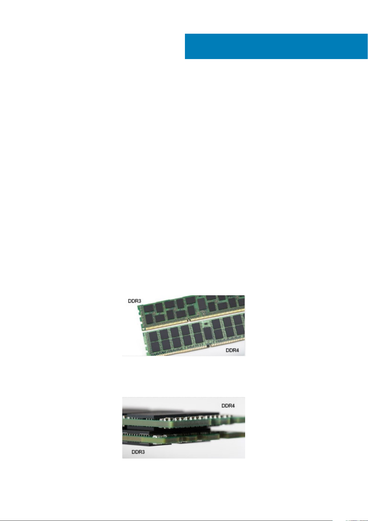
Key notch difference
The key notch on a DDR4 module is in a different location from the key notch on a DDR3 module. Both notches are on the insertion edge
but the notch location on the DDR4 is slightly different, to prevent the module from being installed into an incompatible board or platform.
Figure 1. Notch difference
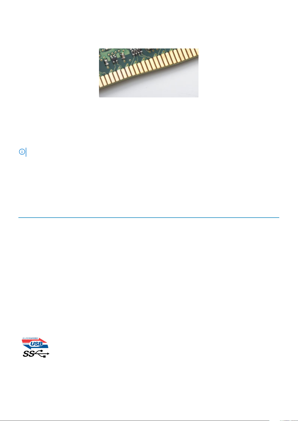
Increased thickness
DDR4 modules are slightly thicker than DDR3, to accommodate more signal layers.
Figure 2. Thickness difference
Technology and components 11
Page 12
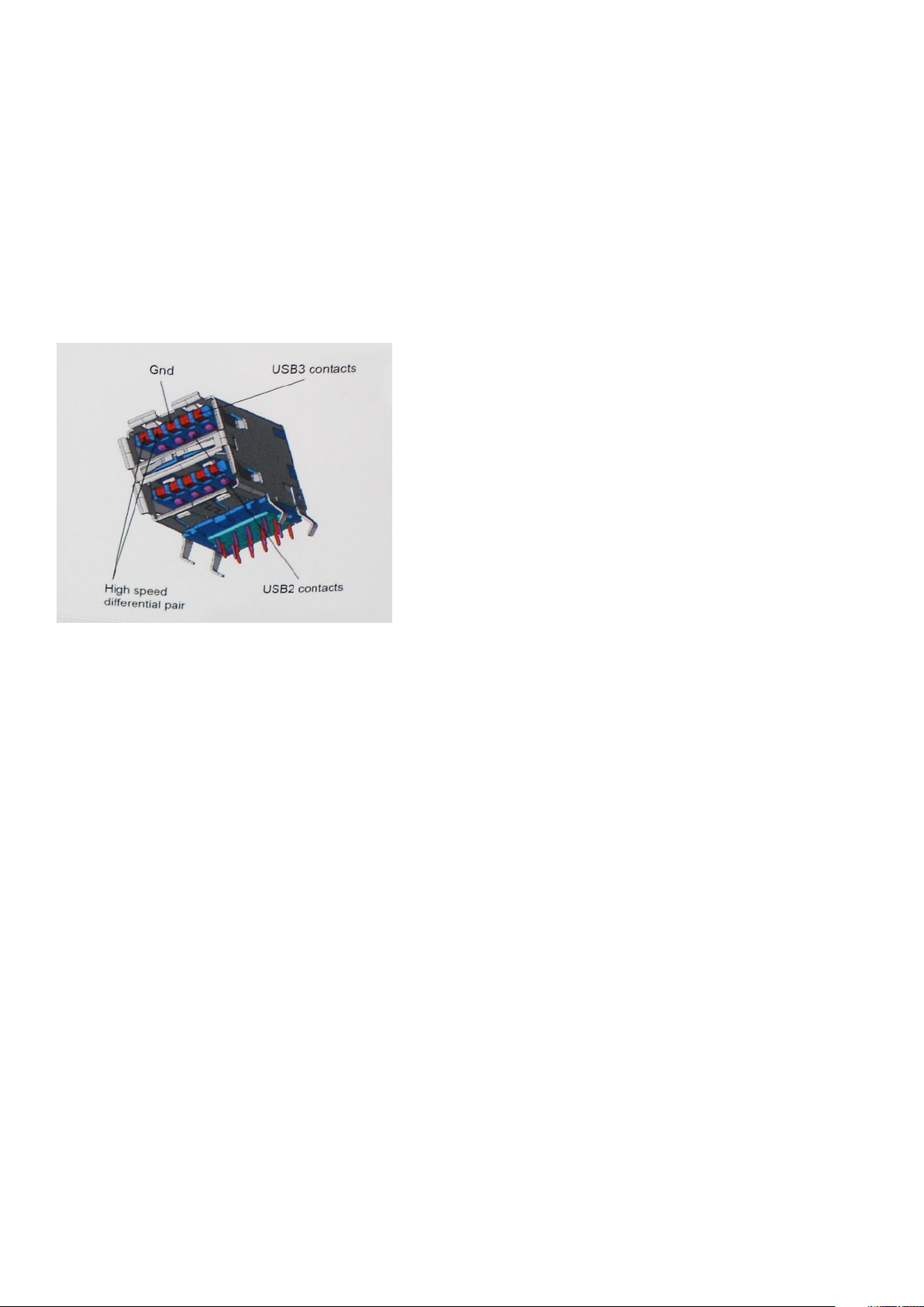
Curved edge
DDR4 modules feature a curved edge to help with insertion and alleviate stress on the PCB during memory installation.
Figure 3. Curved edge
Memory Errors
Memory errors on the system display the new ON-FLASH-FLASH or ON-FLASH-ON failure code. If all memory fails, the LCD does not
turn on. Troubleshoot for possible memory failure by trying known good memory modules in the memory connectors on the bottom of the
system or under the keyboard, as in some portable systems.
NOTE: The DDR4 memory is imbedded in board and not a replaceable DIMM as shown and referred.
USB features
Universal Serial Bus, or USB, was introduced in 1996. It dramatically simplified the connection between host computers and peripheral
devices like mice, keyboards, external drivers, and printers.
Let's take a quick look on the USB evolution referencing to the table below.
Table 1. USB evolution
Type Data Transfer Rate Category Introduction Year
USB 2.0 480 Mbps High Speed 2000
USB 3.0/USB 3.1 Gen 1 5 Gbps Super Speed 2010
USB 3.1 Gen 2 10 Gbps Super Speed 2013
USB 3.0/USB 3.1 Gen 1 (SuperSpeed USB)
For years, the USB 2.0 has been firmly entrenched as the de facto interface standard in the PC world with about 6 billion devices sold, and
yet the need for more speed grows by ever faster computing hardware and ever greater bandwidth demands. The USB 3.0/USB 3.1 Gen 1
finally has the answer to the consumers' demands with a theoretically 10 times faster than its predecessor. In a nutshell, USB 3.1 Gen 1
features are as follows:
• Higher transfer rates (up to 5 Gbps)
• Increased maximum bus power and increased device current draw to better accommodate power-hungry devices
• New power management features
• Full-duplex data transfers and support for new transfer types
• Backward USB 2.0 compatibility
• New connectors and cable
The topics below cover some of the most commonly asked questions regarding USB 3.0/USB 3.1 Gen 1.
12
Technology and components
Page 13
Speed
Currently, there are 3 speed modes defined by the latest USB 3.0/USB 3.1 Gen 1 specification. They are Super-Speed, Hi-Speed and FullSpeed. The new SuperSpeed mode has a transfer rate of 4.8Gbps. While the specification retains Hi-Speed, and Full-Speed USB mode,
commonly known as USB 2.0 and 1.1 respectively, the slower modes still operate at 480Mbps and 12Mbps respectively and are kept to
maintain backward compatibility.
USB 3.0/USB 3.1 Gen 1 achieves the much higher performance by the technical changes below:
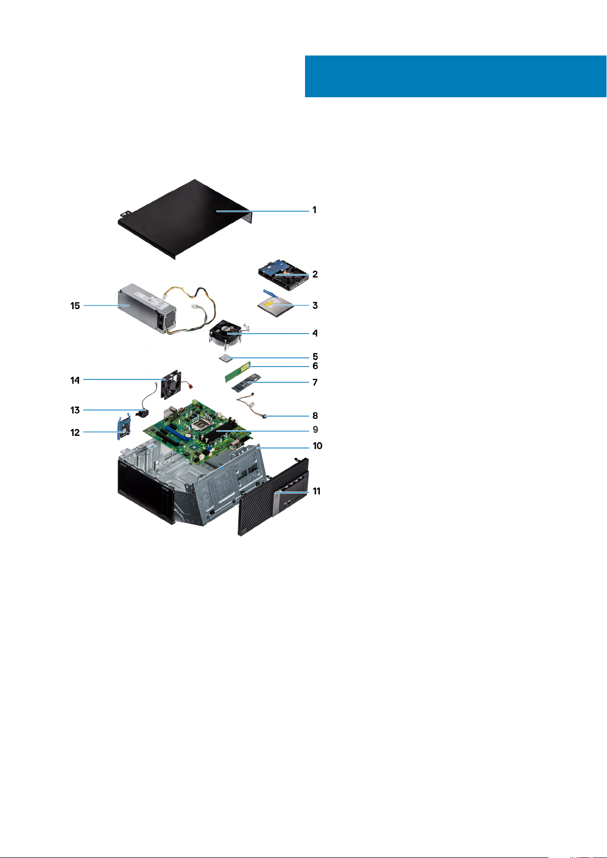
• An additional physical bus that is added in parallel with the existing USB 2.0 bus (refer to the picture below).
• USB 2.0 previously had four wires (power, ground, and a pair for differential data); USB 3.0/USB 3.1 Gen 1 adds four more for two
pairs of differential signals (receive and transmit) for a combined total of eight connections in the connectors and cabling.
• USB 3.0/USB 3.1 Gen 1 utilizes the bidirectional data interface, rather than USB 2.0's half-duplex arrangement. This gives a 10-fold
increase in theoretical bandwidth.
With today's ever increasing demands placed on data transfers with high-definition video content, terabyte storage devices, high
megapixel count digital cameras etc., USB 2.0 may not be fast enough. Furthermore, no USB 2.0 connection could ever come close to the
480Mbps theoretical maximum throughput, making data transfer at around 320Mbps (40MB/s) — the actual real-world maximum.
Similarly, USB 3.0/USB 3.1 Gen 1 connections will never achieve 4.8Gbps. We will likely see a real-world maximum rate of 400MB/s with
overheads. At this speed, USB 3.0/USB 3.1 Gen 1 is a 10x improvement over USB 2.0.
Applications
USB 3.0/USB 3.1 Gen 1 opens up the laneways and provides more headroom for devices to deliver a better overall experience. Where USB
video was barely tolerable previously (both from a maximum resolution, latency, and video compression perspective), it's easy to imagine
that with 5-10 times the bandwidth available, USB video solutions should work that much better. Single-link DVI requires almost 2Gbps
throughput. Where 480Mbps was limiting, 5Gbps is more than promising. With its promised 4.8Gbps speed, the standard will find its way
into some products that previously weren't USB territory, like external RAID storage systems.
Listed below are some of the available SuperSpeed USB 3.0/USB 3.1 Gen 1 products:
• External Desktop USB 3.0/USB 3.1 Gen 1 Hard Drives
• Portable USB 3.0/USB 3.1 Gen 1 Hard Drives
• USB 3.0/USB 3.1 Gen 1 Drive Docks & Adapters
• USB 3.0/USB 3.1 Gen 1 Flash Drives & Readers
• USB 3.0/USB 3.1 Gen 1 Solid-state Drives
• USB 3.0/USB 3.1 Gen 1 RAIDs
• Optical Media Drives
• Multimedia Devices
• Networking
• USB 3.0/USB 3.1 Gen 1 Adapter Cards & Hubs
Technology and components
13
Page 14

Compatibility
The good news is that USB 3.0/USB 3.1 Gen 1 has been carefully planned from the start to peacefully co-exist with USB 2.0. First of all,
while USB 3.0/USB 3.1 Gen 1 specifies new physical connections and thus new cables to take advantage of the higher speed capability of
the new protocol, the connector itself remains the same rectangular shape with the four USB 2.0 contacts in the exact same location as
before. Five new connections to carry receive and transmitted data independently are present on USB 3.0/USB 3.1 Gen 1 cables and only
come into contact when connected to a proper SuperSpeed USB connection.
Windows 8/10 will be bringing native support for USB 3.1 Gen 1 controllers. This is in contrast to previous versions of Windows, which
continue to require separate drivers for USB 3.0/USB 3.1 Gen 1 controllers.
Microsoft announced that Windows 7 would have USB 3.1 Gen 1 support, perhaps not on its immediate release, but in a subsequent
Service Pack or update. It is not out of the question to think that following a successful release of USB 3.0/USB 3.1 Gen 1 support in
Windows 7, SuperSpeed support would trickle down to Vista. Microsoft has confirmed this by stating that most of their partners share the
opinion that Vista should also support USB 3.0/USB 3.1 Gen 1.
USB Type-C
USB Type-C is a new, tiny physical connector. The connector itself can support various exciting new USB standards like USB 3.1 and USB
power delivery (USB PD).
Alternate Mode
USB Type-C is a new connector standard that is very small. It is about a third the size of an old USB Type-A plug. This is a single
connector standard that every device should be able to use. USB Type-C ports can support a variety of different protocols using
“alternate modes,” which allows you to have adapters that can output HDMI, VGA, DisplayPort, or other types of connections from that
single USB port
USB Power Delivery
The USB PD specification is also closely intertwined with USB Type-C. Currently, smartphones, tablets, and other mobile devices often
use a USB connection to charge. A USB 2.0 connection provides up to 2.5 watts of power — that'll charge your phone, but that's about
it. A laptop might require up to 60 watts, for example. The USB Power Delivery specification ups this power delivery to 100 watts. It's bidirectional, so a device can either send or receive power. And this power can be transferred at the same time the device is transmitting
data across the connection.
This could spell the end of all those proprietary laptop charging cables, with everything charging via a standard USB connection. You could
charge your laptop from one of those portable battery packs you charge your smartphones and other portable devices from today. You
could plug your laptop into an external display connected to a power cable, and that external display would charge your laptop as you used
it as an external display — all via the one little USB Type-C connection. To use this, the device and the cable have to support USB Power
Delivery. Just having a USB Type-C connection doesn't necessarily mean they do.
USB Type-C and USB 3.1
USB 3.1 is a new USB standard. USB 3's theoretical bandwidth is 5 Gbps same as of USB 3.1 Gen 1, while USB 3.1 Gen 2's bandwidth is 10
Gbps. That's double the bandwidth, as fast as a first-generation Thunderbolt connector. USB Type-C isn't the same thing as USB 3.1. USB
Type-C is just a connector shape, and the underlying technology could just be USB 2 or USB 3.0. In fact, Nokia's N1 Android tablet uses a
USB Type-C connector, but underneath it's all USB 2.0 — not even USB 3.0. However, these technologies are closely related.
Advantages of DisplayPort over USB Type-C
• Full DisplayPort audio/video (A/V) performance (up to 4K at 60Hz)
• Reversible plug orientation and cable direction
• Backwards compatibility to VGA, DVI with adaptors
• SuperSpeed USB (USB 3.1) data
• Supports HDMI 2.0a and is backwards compatible with previous versions
14
Technology and components
Page 15

HDMI 2.0
This topic explains the HDMI 2.0 and its features along with the advantages.
HDMI (High-Definition Multimedia Interface) is an industry-supported, uncompressed, all-digital audio/video interface. HDMI provides an
interface between any compatible digital audio/video source, such as a DVD player, or A/V receiver and a compatible digital audio and/or
video monitor, such as a digital TV (DTV). The intended applications for HDMI TVs, and DVD players. The primary advantage is cable
reduction and content protection provisions. HDMI supports standard, enhanced, or high-definition video, plus multichannel digital audio
on a single cable.
HDMI 2.0 Features
• HDMI Ethernet Channel - Adds high-speed networking to an HDMI link, allowing users to take full advantage of their IP-enabled
devices without a separate Ethernet cable
• Audio Return Channel - Allows an HDMI-connected TV with a built-in tuner to send audio data "upstream" to a surround audio
system, eliminating the need for a separate audio cable
• 3D - Defines input/output protocols for major 3D video formats, paving the way for true 3D gaming and 3D home theater applications
• Content Type - Real-time signaling of content types between display and source devices, enabling a TV to optimize picture settings
based on content type
• Additional Color Spaces - Adds support for additional color models used in digital photography and computer graphics
• 4K Support - Enables video resolutions far beyond 1080p, supporting next-generation displays that will rival the Digital Cinema
systems used in many commercial movie theaters
• HDMI Micro Connector - A new, smaller connector for phones and other portable devices, supporting video resolutions up to 1080p
• Automotive Connection System - New cables and connectors for automotive video systems, designed to meet the unique
demands of the motoring environment while delivering true HD quality
Advantages of HDMI
• Quality HDMI transfers uncompressed digital audio and video for the highest, crispest image quality.
• Low -cost HDMI provides the quality and functionality of a digital interface while also supporting uncompressed video formats in a
simple, cost-effective manner
• Audio HDMI supports multiple audio formats from standard stereo to multichannel surround sound
• HDMI combines video and multichannel audio into a single cable, eliminating the cost, complexity, and confusion of multiple cables
currently used in A/V systems
• HDMI supports communication between the video source (such as a DVD player) and the DTV, enabling new functionality
Intel Optane memory
Intel Optane memory functions only as a storage accelerator. It neither replaces nor adds to the memory (RAM) installed on your
computer.
NOTE:
Intel Optane memory is supported on computers that meet the following requirements:
• 7th Generation or higher Intel Core i3/i5/i7 processor
• Windows 10 64-bit version 1607 or higher
• Intel Rapid Storage Technology driver version 15.9.1.1018 or higher
Table 2. Intel Optane memory specifications
Feature Specifications
Interface PCIe 3x2 NVMe 1.1
Connector M.2 card slot (2230/2280)
Configurations supported
• 7th Generation or higher Intel Core i3/i5/i7 processor
• Windows 10 64-bit version 1607 or higher
• Intel Rapid Storage Technology driver version 15.9.1.1018 or
higher
Capacity 32 GB
Technology and components 15
Page 16

Enabling Intel Optane memory
1. On the taskbar, click the search box, and type "Intel Rapid Storage Technology".
2. Click Intel Rapid Storage Technology.
3. On the Status tab, click Enable to enable the Intel Optane memory.
4. On the warning screen, select a compatible fast drive, and then click Yes to continue enabling Intel Optane memory.
5. Click Intel Optane memory > Reboot to enable the Intel Optane memory.
NOTE: Applications may take up to three subsequent launches after enablement to see the full performance
benefits.
Disabling Intel Optane memory
CAUTION: After disabling Intel Optane memory, do not uninstall the driver for Intel Rapid Storage Technology as it will
result in a blue screen error. The Intel Rapid Storage Technology user interface can be removed without uninstalling the
driver.
NOTE: Disabling Intel Optane memory is required before removing the SATA storage device, accelerated by the Intel
Optane memory module, from the computer.
1. On the taskbar, click the search box, and then type "Intel Rapid Storage Technology".
2. Click Intel Rapid Storage Technology. The Intel Rapid Storage Technology window is displayed.
3. On the Intel Optane memory tab, click Disable to disable the Intel Optane memory.
4. Click Yes if you accept the warning.
The disabling progress is displayed.
5. Click Reboot to complete disabling Intel Optane memory and restart your computer.
16
Technology and components
Page 17
3
Major components of your system
1. Side cover
2. 3.5-inch Hard drive assembly
3. Optical drive
4. Heatsink assembly
5. Processor
6. Memory module
7. M.2 PCIe SSD
8. Power button
9. System board
10. Front panel door
11. Bezel
12. 2.5-inch Hard drive assembly
13. Speaker
14. System fan
15. Power supply unit
Major components of your system 17
Page 18

NOTE: Dell provides a list of components and their part numbers for the original system configuration purchased. These
parts are available according to warranty coverages purchased by the customer. Contact your Dell sales representative
for purchase options.
18 Major components of your system
Page 19
Removing and installing components
Side cover
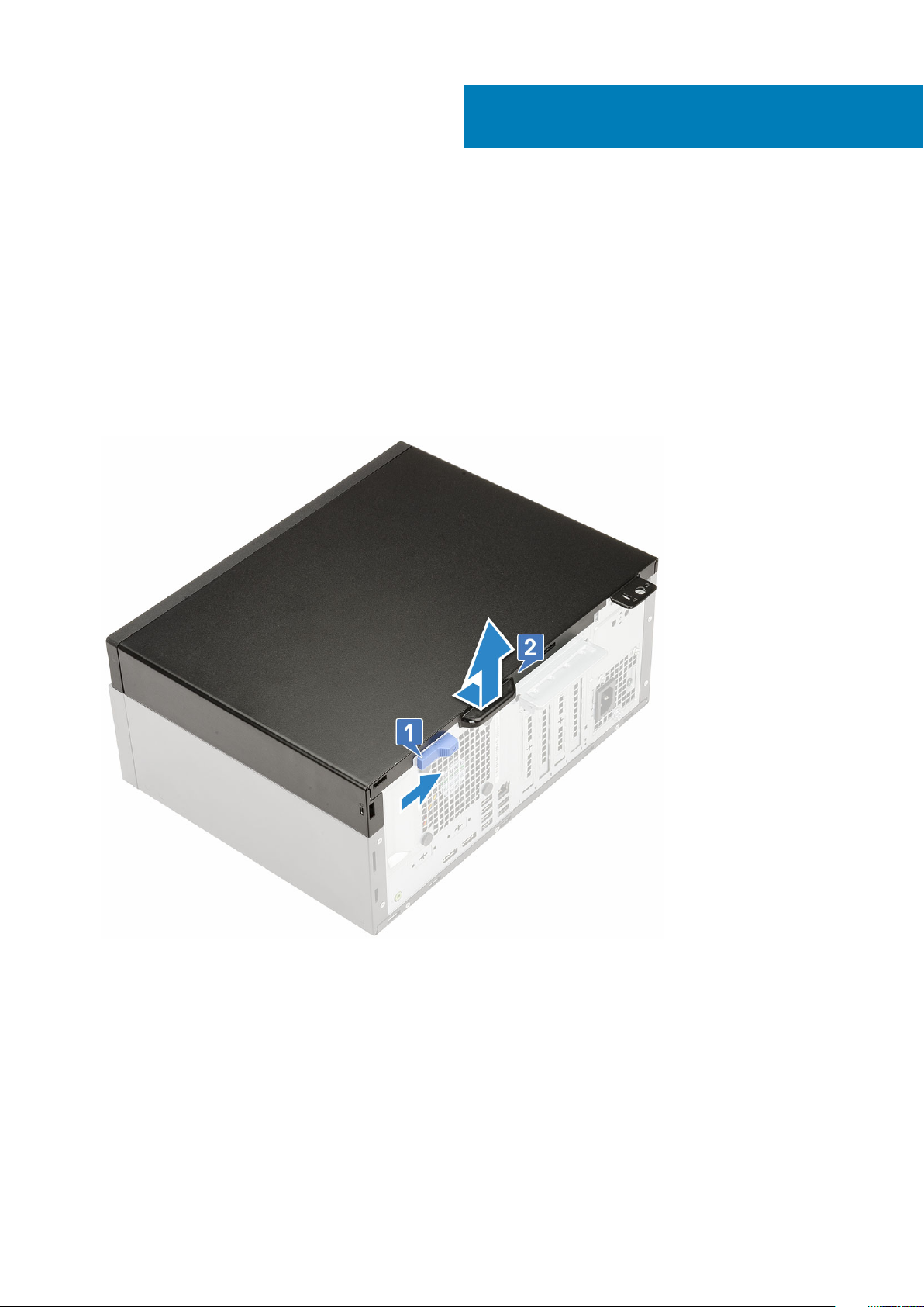
Removing side cover
1. Follow the procedure in Before working inside your computer.
2. To remove the cover:
a) Slide the release latch to release the cover from the system [1].
b) Slide the cover towards the back of the system and lift it from the system [2].
4
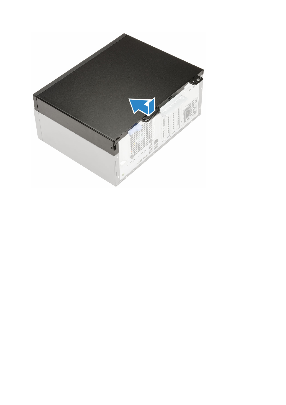
Installing side cover
1. To install the side cover:
a) Place the cover on the system and slide the cover forward until it clicks into place.
Removing and installing components 19
Page 20
2. Follow the procedure in After working inside your computer.
Bezel
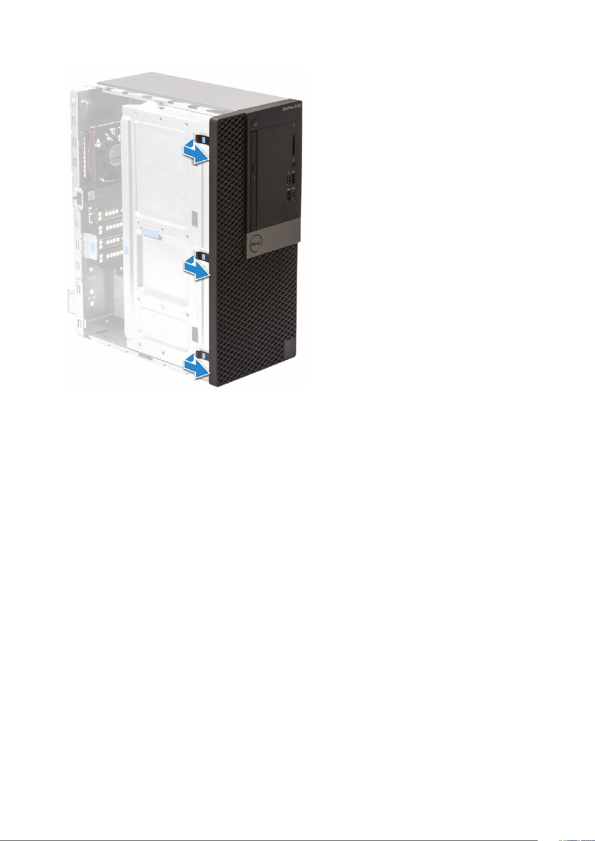
Removing front bezel
1. Follow the procedure in Before working inside your computer.
2. Remove the Side cover.
3. To remove the front bezel:
a) Pry the retention tabs to release the front bezel from the system.
b) Remove the front bezel from the system.
20
Removing and installing components
Page 21
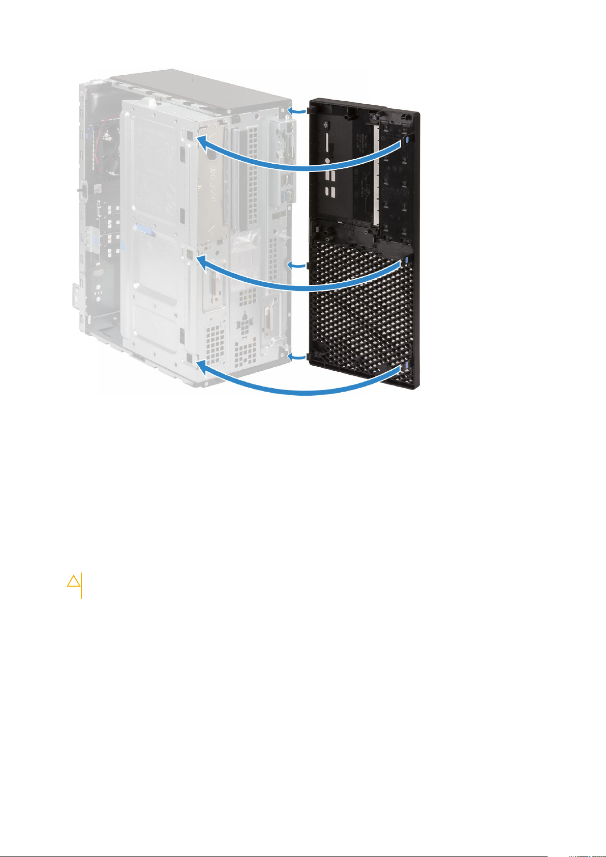
Installing front bezel
1. To install the front bezel:
a) Position the bezel to align the tab holders with the slots on the system chassis.
b) Press the bezel until the tabs click into place.
Removing and installing components
21
Page 22
2. Install the Side cover.
3. Follow the procedure in After working inside your computer.
Front panel door
Opening front panel door
1. Follow the procedure in Before working inside your computer.
2. Remove the:
a) Side cover
b) Front bezel
CAUTION:
the maximum permissible level.
3. Pull the front panel door to open it.
The front panel door opens only to a limited extent. See the printed image on the front panel door for
22
Removing and installing components
Page 23
Closing front panel door
1. Turn the front panel door to close it.
Removing and installing components
23
Page 24
2. Install the:
a) Front bezel
b) Side cover
3. Follow the procedure in After working inside your computer.
Hard drive assembly—3.5-inch and 2.5-inch
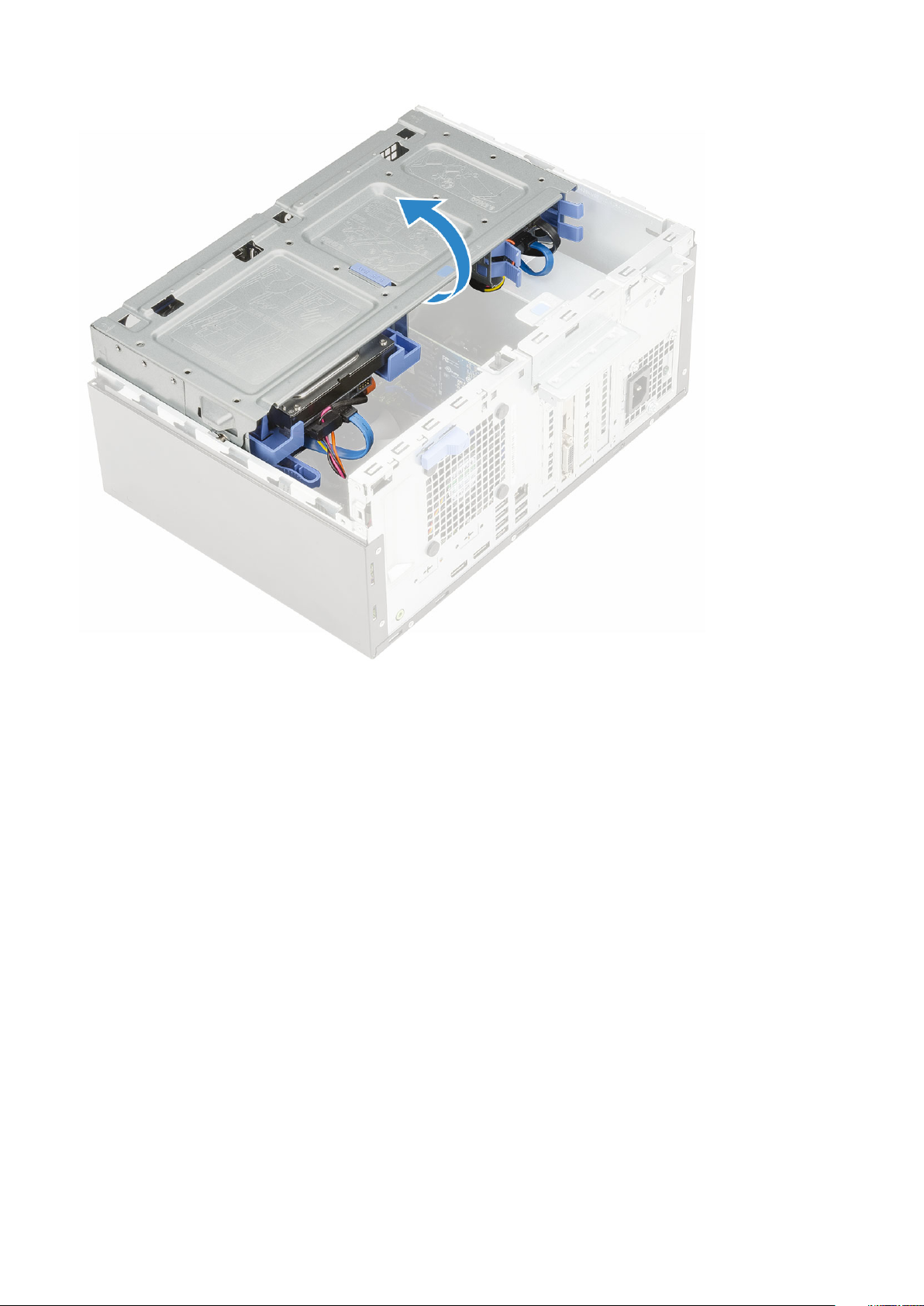
Removing 3.5–inch hard drive assembly
1. Follow the procedure in Before working inside your computer.
2. Remove the:
a) Side cover
b) Front bezel
3. To remove the hard drive assembly:
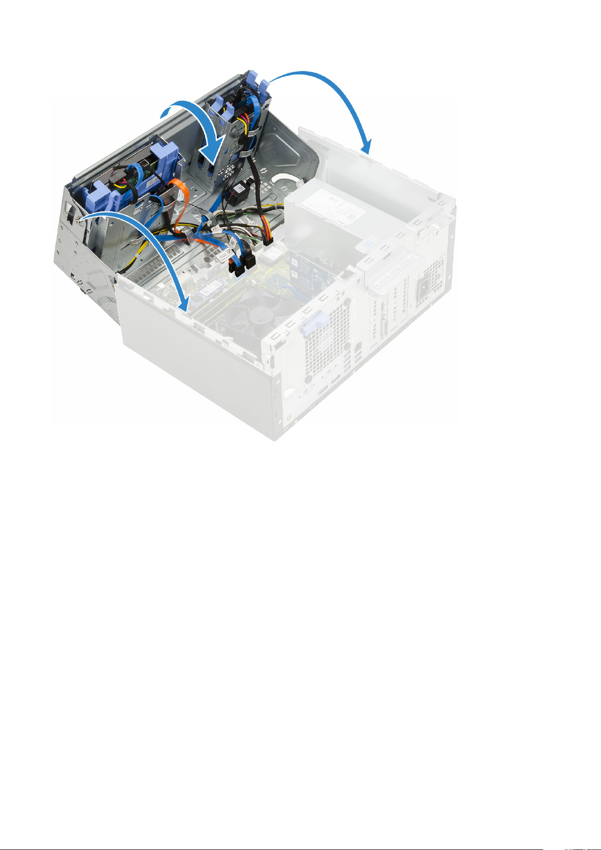
a) Disconnect the SATA cable and the power cable from the connectors on the hard drive.
24
Removing and installing components
Page 25
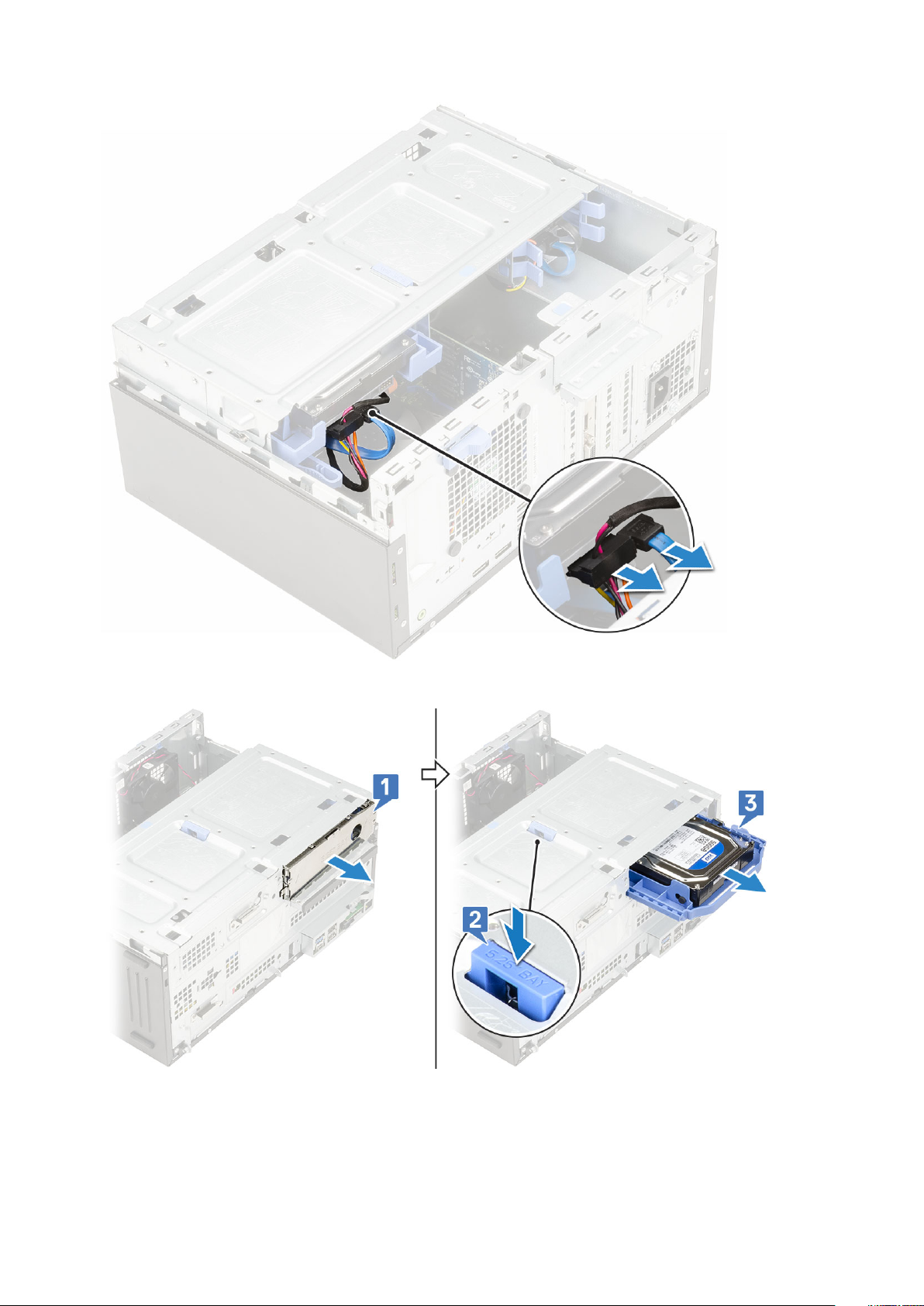
b) Remove the HDD filler bracket from the system [1].
c) Press the blue tab [2] and pull the hard drive assembly out of the system [3].
Removing 3.5–inch hard drive from the hard drive bracket
1. Follow the procedure in Before working inside your computer.
2. Remove the:
Removing and installing components
25
Page 26
a) Side cover
b) Front bezel
c) 3.5-inch HDD assembly
3. To remove the hard drive :
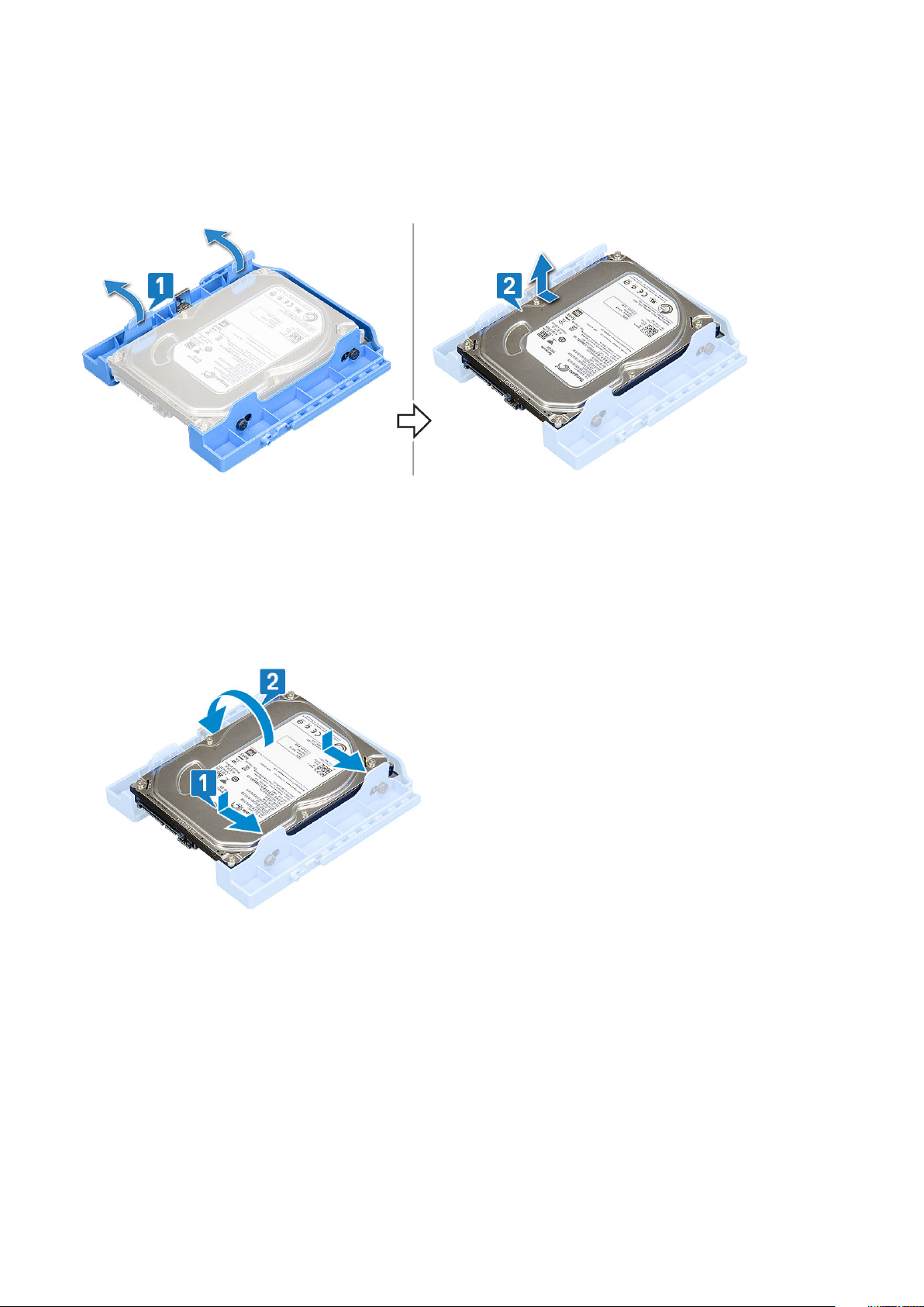
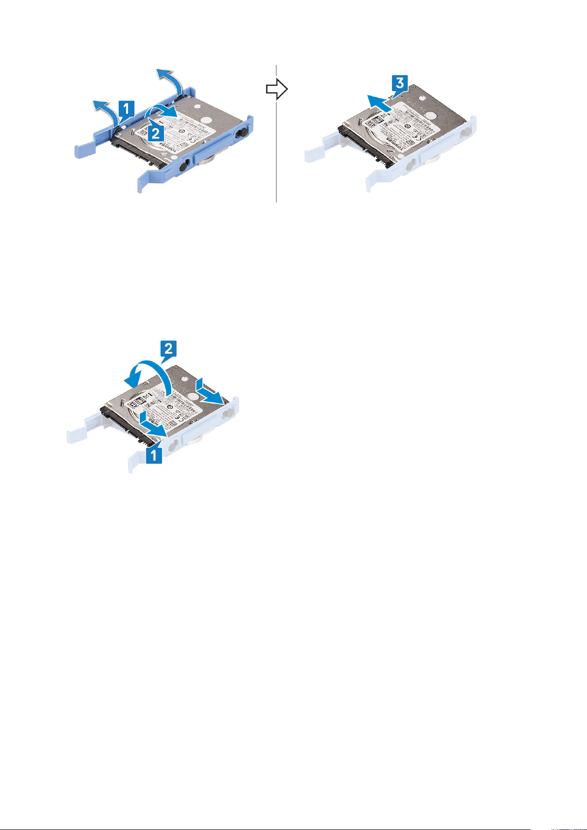
a) Pull one side of the hard drive bracket to disengage the pins on the bracket from the slots on the hard drive [1].
b) Lift the hard drive out of the hard drive bracket [2].
Installing the 3.5–inch hard drive into the hard drive bracket
1. To install the hard drive:
a) Align the hard drive to the side of the hard drive bracket, and pull the other end tabs to insert the pins on the bracket into the hard
drive [1].
b) Insert the hard drive into the hard drive bracket until it clicks into place [2].
2. Install the:
a) 3.5-inch hard drive assembly
b) Front bezel
c) Side cover
3. Follow the procedure in After working inside your computer.
Installing 3.5–inch hard drive assembly
1. Insert the hard drive assembly into the slot on the system until it clicks into place [1].
2. Replace the HDD filler bracket [2].
26
Removing and installing components
Page 27
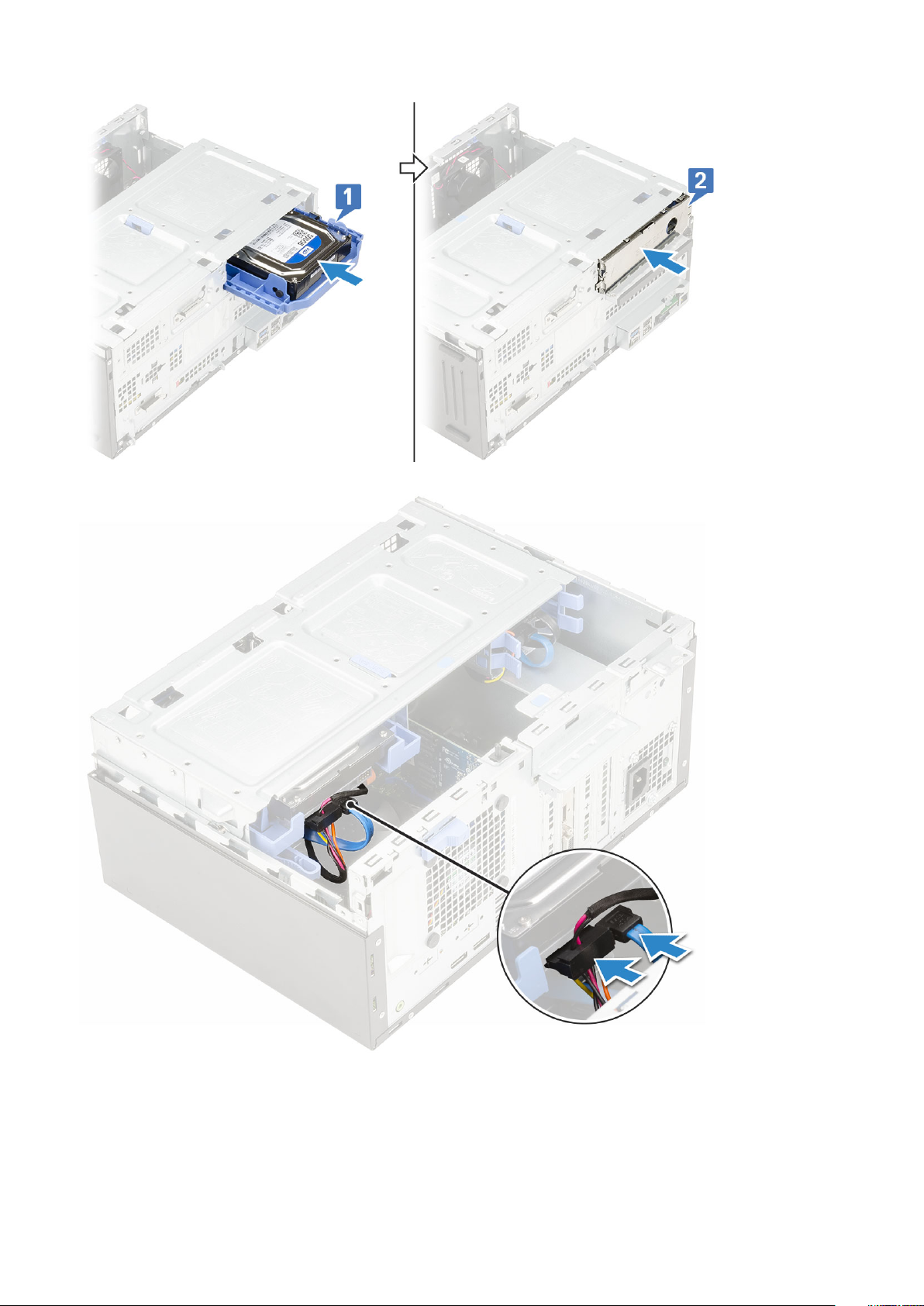
3. Connect the SATA cable and the power cable to the connectors on the hard drive.
4. Install the:
a) Front bezel
b) Side cover
5. Follow the procedure in After working inside your computer.
Removing and installing components
27
Page 28
Removing the 2.5–inch hard drive assembly
1. Follow the procedure in Before working inside your computer.
2. Remove the:
a) Side cover
b) Front bezel
3. Open the front panel door.
4. To remove the hard drive assembly:
a) Disconnect the hard drive data and power cables from the connectors on the 2.5-inch hard drive [1].
b) Press the blue tabs of the assembly on both sides [2] and pull the hard drive assembly out of the system [3].
Removing the 2.5–inch drive from the drive bracket
1. Follow the procedure in Before Working Inside Your Computer.
2. Remove the:
a) Side cover
b) Front bezel
c) 2.5-inch hard drive assembly
3. To remove the drive:
a) Pull one side of the drive bracket to disengage the pins on the bracket from the slots on the drive [1].
b) Lift the drive out of the drive bracket [2].
c) Remove the drive from the bracket [3].
28
Removing and installing components
Page 29
Installing the 2.5–inch hard drive into the hard drive bracket
1. To install the hard drive:
a) Align the hard drive to the side of the hard drive bracket, and pull the other end tabs to insert the pins on the bracket into the hard
drive.
b) Insert the hard drive into the hard drive bracket until it clicks into place [1].
c) Insert the hard drive into the hard drive bracket until it clicks into place [2].
2. Install the:
a) 2.5-inch hard drive assembly
b) Front bezel
c) Side cover
3. Follow the procedure in After working inside your computer.
Installing the 2.5-inch drive assembly
1. To install the hard drive:
a) Insert the hard drive assembly into the slot on the system until it clicks into place [1] .
b) Connect the hard drive data and power cables to the connectors on the 2.5-inch hard drive [2] .
Removing and installing components
29
Page 30
2. Close the front panel door.
3. Install the:
a) Front bezel
b) Side cover
4. Follow the procedure in After Working Inside Your Computer.
Optical drive
Removing optical drive
1. Follow the procedure in Before working inside your computer.
2. Remove the:
a) Side cover
b) Front bezel
3. Open the front panel door.
4. To remove the optical drive assembly:
a) Disconnect the optical drive data cable and power cable from the connectors on the optical drive [1].
You may need to unroute the cables from the tabs under the drive cage to allow you to disconnect the
NOTE:
cables from the connectors.
b) Close the front panel door [2].
30
Removing and installing components
Page 31

c) Press the blue release tab [1] and slide the optical drive out of the system [2].
Removing and installing components
31
Page 32

Installing optical drive
1. To install the optical drive:
a) Close the front panel door.
b) Insert the optical drive into the optical drive bay until it clicks into place.
32
Removing and installing components
Page 33

c) Open the front panel door [1].
d) Route the cables under the drive cage.
e) Connect the optical drive data cable and power cable to the connectors on the optical drive [2].
Removing and installing components
33
Page 34

2. Install the:
a) Front bezel
b) Side cover
3. Follow the procedure in After working inside your computer.
M.2 PCIe SSD
Removing M.2 SSD
1. Follow the procedure in Before working inside your computer.
2. Remove the:
a) Side cover
b) Front bezel
3. Open the front panel door.
4. To remove the M.2 SSD:
a) Remove the single screw that secures the SSD to the system board [1].
b) Slide the M.2 SSD from the connector on the system board [2].
34
Removing and installing components
Page 35

Installing M.2 SSD
1. Insert the M.2 SSD to the connector on the system board [1].
2. Replace the single screw to secure the SSD to the system board [2].
Removing and installing components
35
Page 36

3. Close the front panel door.
4. Install the:
a) Front bezel
b) Side cover
5. Follow the procedure in After working inside your computer.
SD card reader
Removing SD card reader
1. Follow the procedure in Before working inside your computer.
2. Remove the:
a) Side cover
b) Front bezel
3. Open the front panel door.
4. To remove the SD card reader:
a) Disconnect the SD card reader cable from the connector on the system board [1].
b) Remove the screw that secures the SD card reader to the front panel door [2].
c) Lift the SD card reader out of the system [3].
36
Removing and installing components
Page 37

Installing SD card reader
1. To install the SD card reader:
a) Insert the SD card reader into the slot on the front panel door [1].
b) Replace the screw to secure the SD card reader to the front panel door [2].
c) Connect the SD card reader cable to the connector on the system board [3].
Removing and installing components
37
Page 38

2. Close the front panel door.
3. Install the:
a) Front bezel
b) Side cover
4. Follow the procedure in After working inside your computer.
Memory module
Removing memory module
1. Follow the procedure in Before working inside your computer.
2. Remove the:
a) Side cover
b) Front bezel
3. Open the front panel door.
4. To remove the memory module:
a) Pull the clips securing the memory module until the memory module pops up [1].
b) Remove the memory module from the system board [2].
38
Removing and installing components
Page 39

Installing memory module
1. To install the memory module:
a) Align the notch on the memory module with the tab on the memory module connector.
b) Insert the memory module into the memory module socket [1].
c) Press the memory module until the memory module retention tabs click into place [2].
Removing and installing components
39
Page 40

2. Close the front panel door.
3. Install the:
a) Front bezel
b) Side cover
4. Follow the procedure in After working inside your computer.
Expansion card
Removing PCIe expansion card
1. Follow the procedure in Before working inside your computer.
2. Remove the:
a) Side cover
b) Front bezel
3. Open the front panel door.
4. To remove the PCIe expansion card:
a) Pull the release latch to unlock the PCIe expansion card [1].
b) Push the card retention latch [2], and lift the PCIe expansion card out of the computer [3].
This step is applicable only for the connector with card retention latch, otherwise, lift the PCIe expansion
NOTE:
card out of the system.
40 Removing and installing components
Page 41

5. Repeat the steps to remove any additional PCIe expansion card.
Installing PCIe expansion card
1. To install the PCIe expansion card:
a) Insert the PCIe expansion card to the connector on the system board [1].
b) Secure the PCIe expansion card by pushing the card retention latch until it clicks into place .
NOTE: This step is applicable only for the connector with card retention latch, otherwise, skip this step.
Removing and installing components 41
Page 42

c) Pull the release latch forward to close [2].
d) Repeat the steps to install any additional PCIe expansion card.
2. Close the front panel door.
3. Install the:
a) Front bezel
b) Side cover
4. Follow the procedure in After working inside your computer.
Optional VGA module
Removing optional VGA module
1. Follow the procedure in Before working inside your computer.
2. Remove the:
a) Side cover
b) Front bezel
3. Open the front panel door.
4. Remove the system fan.
5. To remove the optional VGA module:
a) Remove the two (M3X3) screws that secure the optional VGA module to the system.
42
Removing and installing components
Page 43

b) Disconnect the VGA cable from the connector on the system board [1].
c) Remove the VGA module from the system [2].
Installing optional VGA module
1. To remove the metal bracket as shown below, insert a flathead screwdriver in the hole of the bracket [1], push the bracket to release
the bracket [2], and then lift the bracket out from the system.
2. Insert the VGA module into its slot from the inside of your computer [1] and connect the VGA cable to the connector on the system
board [2].
Removing and installing components
43
Page 44

3. Replace the two (M3X3) screws to secure the optional VGA module to the system.
4. Install the system fan .
5. Close the front panel door.
6. Install the:
a) Front bezel
b) Side cover
7. Follow the procedure in After working inside your computer.
Power supply unit
Removing power supply unit or PSU
1. Follow the procedure in Before working inside your computer.
2. Remove the:
a) Side cover
b) Front bezel
3. Open the front panel door.
4. To release the PSU:
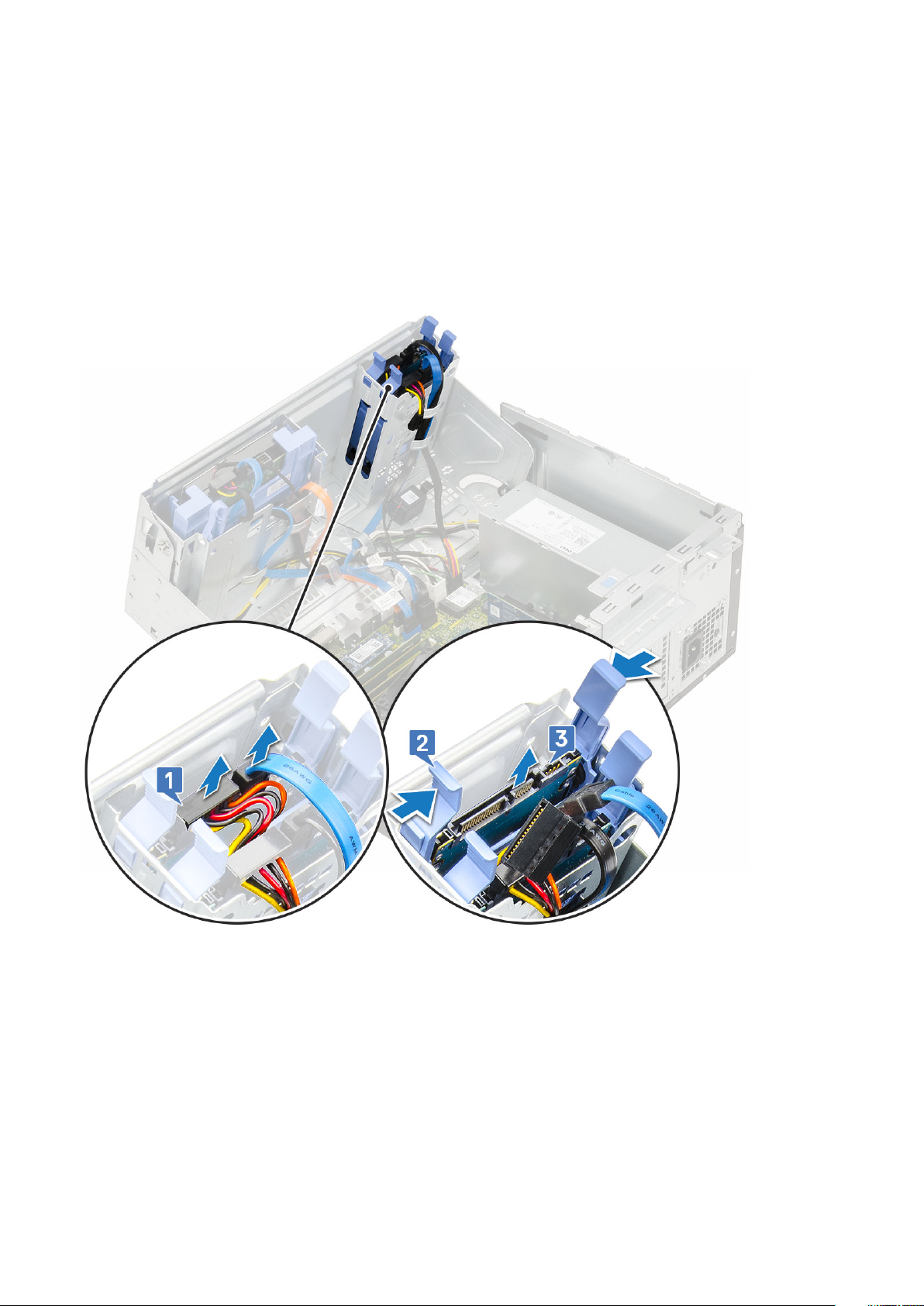
a) Disconnect the PSU cables from the connectors on the system board [1].
b) Unroute the PSU cables from the retention clips [2, 3, 4, 5].
c) Disconnect the PSU cables from the connectors on the system board [6].
44
Removing and installing components
Page 45

5. To remove the PSU:
a) Remove the 3 screws that secure the PSU to the system [1].
b) Press the release tab [2].
c) Slide and lift the PSU away from the computer [3].
Removing and installing components
45
Page 46

Installing power supply unit or PSU
1. To install the PSU:
a) Insert the PSU into the PSU slot and slide it towards the back of the system until it clicks into place [1].
b) Replace the three screws to secure the PSU to the computer [2] .
46
Removing and installing components
Page 47

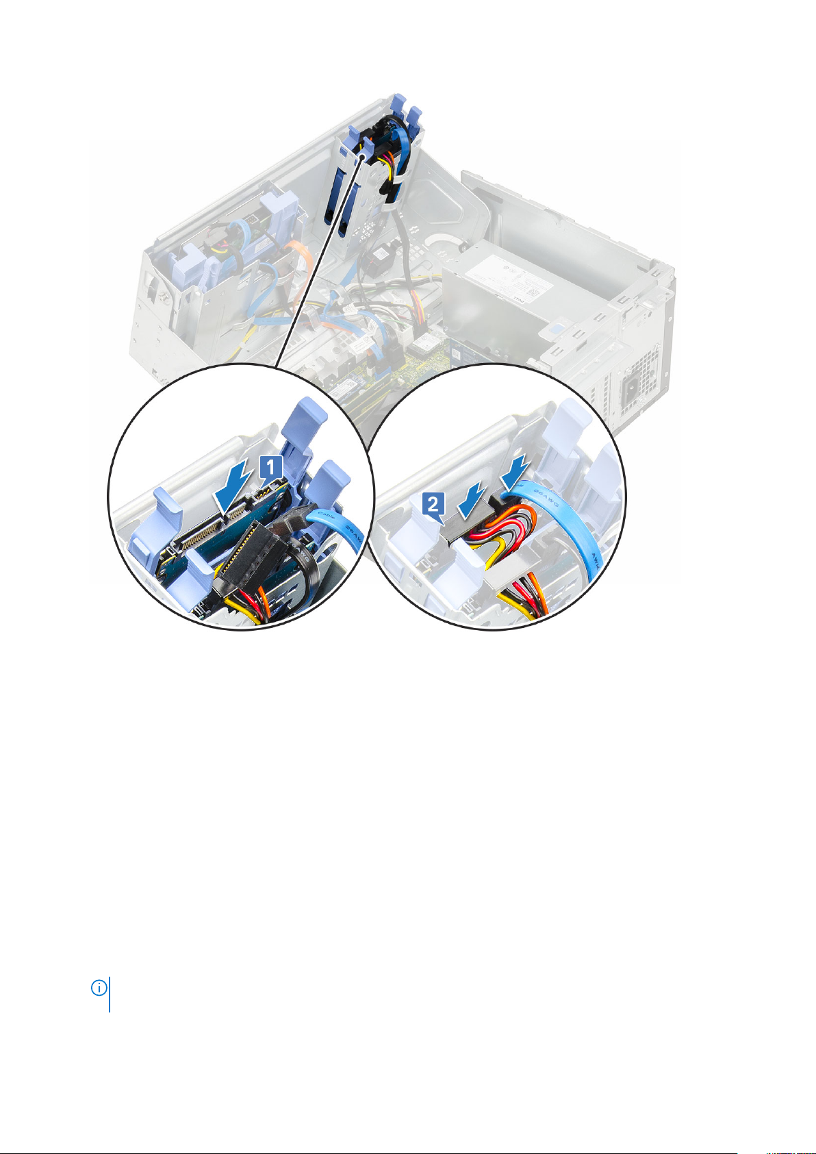
c) Connect the PSU cables to the connectors on the system board [1].
d) Route the PSU cables through the retention clips [2, 3, 4, 5].
e) Connect the PSU cable to the connector on the system board [6].
Removing and installing components
47
Page 48

2. Close the front panel door.
3. Install the:
a) Front bezel
b) Side cover
4. Follow the procedure in After working inside your computer.
Intrusion switch
Removing intrusion switch
1. Follow the procedure in Before working inside your computer.
2. Remove the:
a) Side cover
b) Front bezel
3. Open the front panel door.
4. To remove the intrusion switch:
a) Disconnect the intrusion switch cable from the connector on the system board [1].
b) Unroute the intrusion switch cable from the fan grommets [2].
c) Slide the intrusion switch and push it to remove from the computer [3].
48
Removing and installing components
Page 49

Installing intrusion switch
1. Insert the intrusion switch into the slot on the system [1].
2. Route the intrusion switch cable through the fan grommet [2].
3. Connect the intrusion switch cable to the connector on the system board [3].
Removing and installing components
49
Page 50

4. Close the front panel door.
5. Install the:
a) Front bezel
b) Side cover
6. Follow the procedure in After working inside your computer.
Power button
Removing power button
1. Follow the procedure in Before working inside your computer.
2. Remove the:
a) Side cover
b) Front bezel
3. Open the front panel door.
4. To release the power button:
a) Disconnect the power button cable from the system board [1].
b) Unroute the power button cable through the retention clip [2].
c) Press the release tabs using a plastic scribe and slide the power button out from the front of the system [3].
d) Close the front panel door [4].
50
Removing and installing components
Page 51

5. Pull the power button out from the computer.
Removing and installing components
51
Page 52

Installing power button
1. Insert the power switch into the slot from the front of the computer and press it until it clicks into place.
52
Removing and installing components
Page 53

2. Open the front panel door [1]
3. Route the power switch cable from the power button through the retention clip [2, 3].
4. Align the cable with the pins on the connector and connect the power button cable [4].
Removing and installing components
53
Page 54

5. Close the front panel door.
6. Install the:
a) Front bezel
b) Side cover
7. Follow the procedure in After working inside your computer.
Speaker
Removing speaker
1. Follow the procedure in Before working inside your computer.
2. Remove the:
a) Side cover
b) Front bezel
3. Open the front panel door.
4. To remove the speaker:
a) Disconnect the speaker cable from the connector on the system board [1].
b) Lift the tab [2], and slide the speaker out of the slot [3].
54
Removing and installing components
Page 55

Installing speaker
1. Insert the speaker into the slot and press it until it clicks into place [1].
2. Connect the speaker cable to the connector on the system board [2].
Removing and installing components
55
Page 56

3. Close the front panel door.
4. Install the:
a) Front bezel
b) Side cover
5. Follow the procedure in After working inside your computer.
Coin cell battery
Removing coin cell battery
1. Follow the procedure in Before working inside your computer.
2. Remove the:
a) Side cover
b) Front bezel
3. Open the front panel door.
4. To remove the coin cell battery:
a) Press the release latch until the coin cell battery pops out [1].
b) Remove the coin cell battery from the connector on the system board [2].
56
Removing and installing components
Page 57

NOTE: Removing the coin cell battery may reset the system board BIOS/Settings
Installing the coin cell battery
1. Hold the coin cell battery with the "+" sign facing up and slide it under the securing tabs at the positive side of the connector [1].
2. Press the battery into the connector until it locks into place [2].
Removing and installing components
57
Page 58

3. Close the front panel door.
4. Install the:
a) Front bezel
b) Side cover
5. Follow the procedure in After working inside your computer.
Heat sink fan
Removing heat sink fan
1. Follow the procedure in Before working inside your computer.
2. Remove the:
a) Side cover
b) Front bezel
3. Open the front panel door.
4. To remove the heatsink fan assembly:
a) Disconnect the heatsink fan assembly cable from the connector on the system board [1].
b) Remove the screws that secure the fan to the heat sink [2].
NOTE: Ensure to insert the Torx screw driver from top screw hole to remove the screws.
c) Lift the heatsink fan away from the computer [3].
58
Removing and installing components
Page 59

Installing heatsink fan
1. Place the fan on the heatsink assembly [1].
2. Tighten the screws (4) to secure the fan to the heatsink assembly [2].
3. Connect the heatsink fan assembly cable to the connector on the system board [3].
Removing and installing components
59
Page 60

4. Close the front panel door.
5. Install the:
a) Front bezel
b) Side cover
6. Follow the procedure in After working inside your computer.
Heat sink
Removing heatsink assembly
1. Follow the procedure in Before working inside your computer.
2. Remove the:
a) Side cover
b) Front bezel
3. Open the front panel door.
4. To remove the heatsink assembly:
a) Disconnect the heatsink fan assembly cable from the connector on the system board [1].
b) Loosen the captive screws (4) that secure the heatsink assembly to the system board [2].
NOTE: Remove the screw in the sequential order (1,2,3,4) as printed on the system board.
c) Lift the heatsink assembly away from the computer [3].
60
Removing and installing components
Page 61

Installing heatsink assembly
1. Align the screws of the heatsink assembly with the holders on the system board and place the heatsink assembly on the processor [1].
2. Tighten the captive screws to secure the heatsink assembly to the system board [2].
NOTE: Tighten the screws in a sequential order (1,2,3,4) as printed on the system board.
3. Connect the heatsink fan assembly cable from the connector on the system board [3].
Removing and installing components
61
Page 62

4. Close the front panel door.
5. Install the:
a) Front bezel
b) Side cover
6. Follow the procedure in After working inside your computer.
Processor
Removing processor
1. Follow the procedure in Before working inside your computer.
2. Remove the:
a) Side cover
b) Front bezel
3. Open the front panel door.
4. Remove the heatsink assembly.
5. To remove the processor:
a) Release the socket lever by pushing the lever down and out from under the tab on the processor shield [1].
b) Lift the lever upward and lift the processor shield [2].
c) Lift the processor out of the socket [3].
62
Removing and installing components
Page 63

CAUTION: Do not touch the processor socket pins, they are fragile and can be permanently damaged. Be careful
not to bend the pins in the processor socket when removing the processor out of the socket.
Installing processor
1. Place the processor on the socket such that the slots on the processor align with the socket keys [1].
CAUTION:
the socket.
2. Close the processor shield by sliding it under the retention screw [2].
3. Lower the socket lever and push it under the tab to lock it [3].
Do not use force to seat the processor. When the processor is positioned correctly, it engages easily into
Removing and installing components
63
Page 64

4. Install the heatsink assembly.
5. Close the front panel door.
6. Install the:
a) Front bezel
b) Side cover
7. Follow the procedure in After working inside your computer.
System fan
Removing system fan
1. Follow the procedure in Before working inside your computer.
2. Remove the:
a) Side cover
b) Front bezel
3. Open the front panel door.
4. To remove the system fan:
a) Disconnect the intrusion switch cable from the connector on the system board [1].
b) Unroute the intrusion switch cable from the fan grommet [2].
64
Removing and installing components
Page 65

c) Disconnect the system fan cable from the connector on the system board [1].
d) Stretch the grommets securing the fan to the computer to ease the removal of the fan [2].
e) Slide the system fan out of the computer [3].
Removing and installing components
65
Page 66

Installing system fan
1. Insert the grommets into the slots on the back of the computer.
2. Hold the system fan with the cable facing the bottom of the computer.
3. Align the grooves of the system fan with the grommets on the chassis wall.
4. Pass the grommets through the corresponding grooves on the system fan [1].
5. Stretch the grommets and slide the system fan toward the computer until it locks into place [2].
NOTE: Install the lower two grommets first.
6. Connect the system fan cable to the connector on the system board [3].
66
Removing and installing components
Page 67

7. Route the intrusion switch cable through the fan grommet [2].
8. Insert the intrusion switch cable into the system board [1].
Removing and installing components
67
Page 68

9. Close the front panel door.
10. Install the:
a) Front bezel
b) Side cover
11. Follow the procedure in After working inside your computer.
System board
Removing system board
1. Follow the procedure in Before working inside your computer.
2. Remove the:
a) Side cover
b) Front bezel
3. Open the front panel door.
4. Remove the:
a) Heatsink assembly
b) Processor
c) Expansion card
d) M.2 SSD
e) SD card reader
f) Memory module
g) Heatsink fan
5. Disconnect the following cables:
a) Intrusion switch
b) Power switch
68
Removing and installing components
Page 69

6. Disconnect the following cables from the system board:
a) CPU power [1]
b) Hard drive data and optical drive data [2]
c) Speaker [3]
d) System power [4]
e) SATA [5]
7. To remove the system board:
a) Remove the screws that secure the system board to the computer [1].
Removing and installing components
69
Page 70

b) Slide and lift the system board away from the computer [1, 2].
70
Removing and installing components
Page 71

Front panel door
Opening front panel door
1. Follow the procedure in Before working inside your computer.
2. Remove the:
a) Side cover
b) Front bezel
CAUTION: The front panel door opens only to a limited extent. See the printed image on the front panel door for
the maximum permissible level.
3. Pull the front panel door to open it.
Closing front panel door
1. Turn the front panel door to close it.
Removing and installing components
71
Page 72

2. Install the:
a) Front bezel
b) Side cover
3. Follow the procedure in After working inside your computer.
3.5-inch hard drive
Removing 3.5–inch hard drive assembly
1. Follow the procedure in Before working inside your computer.
2. Remove the:
a) Side cover
b) Front bezel
3. To remove the hard drive assembly:
a) Disconnect the SATA cable and the power cable from the connectors on the hard drive.
72
Removing and installing components
Page 73

b) Remove the HDD filler bracket from the system [1].
c) Press the blue tab [2] and pull the hard drive assembly out of the system [3].
Installing 3.5–inch hard drive assembly
1. Insert the hard drive assembly into the slot on the system until it clicks into place [1].
2. Replace the HDD filler bracket [2].
Removing and installing components
73
Page 74

3. Connect the SATA cable and the power cable to the connectors on the hard drive.
4. Install the:
a) Front bezel
b) Side cover
5. Follow the procedure in After working inside your computer.
74
Removing and installing components
Page 75

3.5-inch hard drive
Removing 3.5–inch hard drive from the hard drive bracket
1. Follow the procedure in Before working inside your computer.
2. Remove the:
a) Side cover
b) Front bezel
c) 3.5-inch HDD assembly
3. To remove the hard drive :
a) Pull one side of the hard drive bracket to disengage the pins on the bracket from the slots on the hard drive [1].
b) Lift the hard drive out of the hard drive bracket [2].
Installing the 3.5–inch hard drive into the hard drive bracket
1. To install the hard drive:
a) Align the hard drive to the side of the hard drive bracket, and pull the other end tabs to insert the pins on the bracket into the hard
drive [1].
b) Insert the hard drive into the hard drive bracket until it clicks into place [2].
2. Install the:
a) 3.5-inch hard drive assembly
b) Front bezel
c) Side cover
3. Follow the procedure in After working inside your computer.
Removing and installing components
75
Page 76

2.5-inch hard drive assembly
Removing the 2.5–inch hard drive assembly
1. Follow the procedure in Before working inside your computer.
2. Remove the:
a) Side cover
b) Front bezel
3. Open the front panel door.
4. To remove the hard drive assembly:
a) Disconnect the hard drive data and power cables from the connectors on the 2.5-inch hard drive [1].
b) Press the blue tabs of the assembly on both sides [2] and pull the hard drive assembly out of the system [3].
Installing the 2.5-inch drive assembly
1. To install the hard drive:
a) Insert the hard drive assembly into the slot on the system until it clicks into place [1] .
b) Connect the hard drive data and power cables to the connectors on the 2.5-inch hard drive [2] .
76
Removing and installing components
Page 77

2. Close the front panel door.
3. Install the:
a) Front bezel
b) Side cover
4. Follow the procedure in After Working Inside Your Computer.
2.5-inch hard drive
Removing the 2.5–inch drive from the drive bracket
1. Follow the procedure in Before Working Inside Your Computer.
2. Remove the:
a) Side cover
b) Front bezel
c) 2.5-inch hard drive assembly
3. To remove the drive:
a) Pull one side of the drive bracket to disengage the pins on the bracket from the slots on the drive [1].
b) Lift the drive out of the drive bracket [2].
c) Remove the drive from the bracket [3].
Removing and installing components
77
Page 78

Installing the 2.5–inch hard drive into the hard drive bracket
1. To install the hard drive:
a) Align the hard drive to the side of the hard drive bracket, and pull the other end tabs to insert the pins on the bracket into the hard
drive.
b) Insert the hard drive into the hard drive bracket until it clicks into place [1].
c) Insert the hard drive into the hard drive bracket until it clicks into place [2].
2. Install the:
a) 2.5-inch hard drive assembly
b) Front bezel
c) Side cover
3. Follow the procedure in After working inside your computer.
Optical drive
Removing optical drive
1. Follow the procedure in Before working inside your computer.
2. Remove the:
a) Side cover
b) Front bezel
3. Open the front panel door.
4. To remove the optical drive assembly:
a) Disconnect the optical drive data cable and power cable from the connectors on the optical drive [1].
You may need to unroute the cables from the tabs under the drive cage to allow you to disconnect the
NOTE:
cables from the connectors.
b) Close the front panel door [2].
78
Removing and installing components
Page 79

c) Press the blue release tab [1] and slide the optical drive out of the system [2].
Removing and installing components
79
Page 80

Installing optical drive
1. To install the optical drive:
a) Insert the optical drive into the optical drive bay until it clicks into place [1].
b) Open the front panel door [2].
80
Removing and installing components
Page 81

c) Route the cables under the drive cage.
d) Connect the optical drive data cable and power cable to the connectors on the optical drive [1] .
e) Close the front panel door [2].
Removing and installing components
81
Page 82

2. Install the:
a) Front bezel
b) Side cover
3. Follow the procedure in After working inside your computer.
M.2 SSD
Removing M.2 SSD
1. Follow the procedure in Before working inside your computer.
2. Remove the:
a) Side cover
b) Front bezel
3. Open the front panel door.
4. To remove the M.2 SSD:
a) Remove the single screw that secures the SSD to the system board [1].
b) Slide the M.2 SSD from the connector on the system board [2].
82
Removing and installing components
Page 83

Installing M.2 SSD
1. Insert the M.2 SSD to the connector on the system board [1].
2. Replace the single screw to secure the SSD to the system board [2].
Removing and installing components
83
Page 84

3. Close the front panel door.
4. Install the:
a) Front bezel
b) Side cover
5. Follow the procedure in After working inside your computer.
SD card reader
Removing SD card reader
1. Follow the procedure in Before working inside your computer.
2. Remove the:
a) Side cover
b) Front bezel
3. Open the front panel door.
4. To remove the SD card reader:
a) Disconnect the SD card reader cable from the connector on the system board [1].
b) Remove the screw that secures the SD card reader to the front panel door [2].
c) Lift the SD card reader out of the system [3].
84
Removing and installing components
Page 85

Installing SD card reader
1. To install the SD card reader:
a) Insert the SD card reader into the slot on the front panel door [1].
b) Replace the screw to secure the SD card reader to the front panel door [2].
c) Connect the SD card reader cable to the connector on the system board [3].
Removing and installing components
85
Page 86

2. Close the front panel door.
3. Install the:
a) Front bezel
b) Side cover
4. Follow the procedure in After working inside your computer.
Memory module
Removing memory module
1. Follow the procedure in Before working inside your computer.
2. Remove the:
a) Side cover
b) Front bezel
3. Open the front panel door.
4. To remove the memory module:
a) Pull the clips securing the memory module until the memory module pops up [1].
b) Remove the memory module from the system board [2].
86
Removing and installing components
Page 87

Installing memory module
1. To install the memory module:
a) Align the notch on the memory module with the tab on the memory module connector.
b) Insert the memory module into the memory module socket [1].
c) Press the memory module until the memory module retention tabs click into place [2].
Removing and installing components
87
Page 88

2. Close the front panel door.
3. Install the:
a) Front bezel
b) Side cover
4. Follow the procedure in After working inside your computer.
Expansion card
Removing PCIe expansion card
1. Follow the procedure in Before working inside your computer.
2. Remove the:
a) Side cover
b) Front bezel
3. Open the front panel door.
4. To remove the PCIe expansion card:
a) Pull the release latch to unlock the PCIe expansion card [1].
b) Push the card retention latch [2], and lift the PCIe expansion card out of the computer [3].
This step is applicable only for the connector with card retention latch, otherwise, lift the PCIe expansion
NOTE:
card out of the system.
88 Removing and installing components
Page 89

5. Repeat the steps to remove any additional PCIe expansion card.
Installing PCIe expansion card
1. To install the PCIe expansion card:
a) Insert the PCIe expansion card to the connector on the system board [1].
b) Secure the PCIe expansion card by pushing the card retention latch until it clicks into place [2].
c) Repeat the steps to install any additional PCIe expansion card.
Removing and installing components
89
Page 90

2. Close the front panel door.
3. Install the:
a) Front bezel
b) Side cover
4. Follow the procedure in After working inside your computer.
Power supply unit
Removing power supply unit or PSU
1. Follow the procedure in Before working inside your computer.
2. Remove the:
a) Side cover
b) Front bezel
3. Open the front panel door.
4. To release the PSU:
a) Disconnect the PSU cables from the connectors on the system board [1].
b) Unroute the PSU cables from the retention clips [2, 3, 4, 5].
c) Disconnect the PSU cables from the connectors on the system board [6].
90
Removing and installing components
Page 91

5. To remove the PSU:
a) Remove the 3 screws that secure the PSU to the system [1].
b) Press the release tab [2].
c) Slide and lift the PSU away from the computer [3].
Removing and installing components
91
Page 92

Installing power supply unit or PSU
1. To install the PSU:
a) Insert the PSU into the PSU slot and slide it towards the back of the system until it clicks into place [1].
b) Replace the three screws to secure the PSU to the computer [2] .
92
Removing and installing components
Page 93
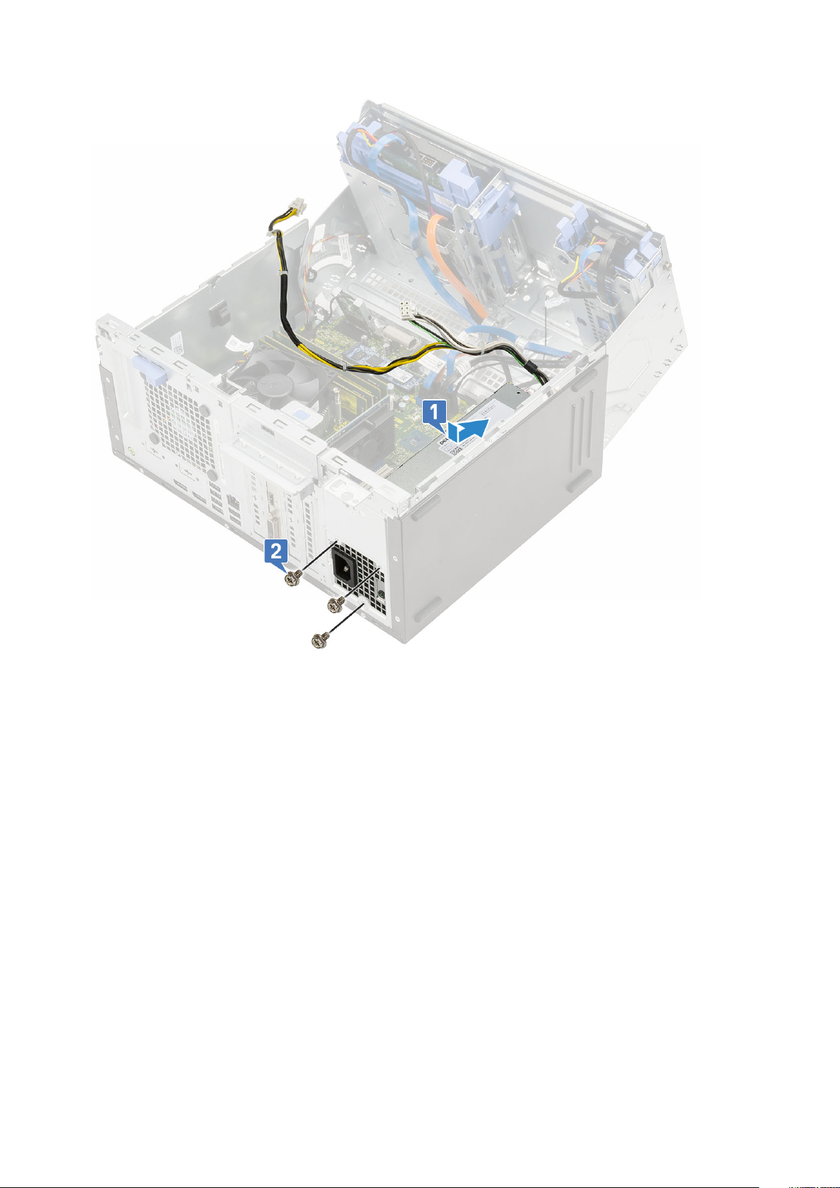
c) Connect the PSU cables to the connectors on the system board [1].
d) Route the PSU cables through the retention clips [2, 3, 4, 5].
e) Connect the PSU cable to the connector on the system board [6].
Removing and installing components
93
Page 94

2. Close the front panel door.
3. Install the:
a) Front bezel
b) Side cover
4. Follow the procedure in After working inside your computer.
Intrusion switch
Removing intrusion switch
1. Follow the procedure in Before working inside your computer.
2. Remove the:
a) Side cover
b) Front bezel
3. Open the front panel door.
4. To remove the intrusion switch:
a) Disconnect the intrusion switch cable from the connector on the system board [1].
b) Unroute the intrusion switch cable from the fan grommets [2].
c) Slide the intrusion switch and push it to remove from the computer [3].
94
Removing and installing components
Page 95

Installing intrusion switch
1. Insert the intrusion switch into the slot on the system [1].
2. Route the intrusion switch cable through the fan grommet [2].
3. Connect the intrusion switch cable to the connector on the system board [3].
Removing and installing components
95
Page 96

4. Close the front panel door.
5. Install the:
a) Front bezel
b) Side cover
6. Follow the procedure in After working inside your computer.
Power button
Removing power button
1. Follow the procedure in Before working inside your computer.
2. Remove the:
a) Side cover
b) Front bezel
3. Open the front panel door.
4. To release the power button:
a) Disconnect the power button cable from the system board [1].
b) Unroute the power button cable through the retention clip [2].
c) Press the release tabs using a plastic scribe and slide the power button out from the front of the system [3].
d) Close the front panel door [4].
96
Removing and installing components
Page 97

5. Pull the power button out from the computer.
Removing and installing components
97
Page 98

Installing power button
1. Insert the power switch into the slot from the front of the computer and press it until it clicks into place [1].
2. Open the front panel door [2]
98
Removing and installing components
Page 99

3. Route the power switch cable from the power button through the retention clip [2].
4. Align the cable with the pins on the connector and connect the power button cable [3].
Removing and installing components
99
Page 100

5. Close the front panel door.
6. Install the:
a) Front bezel
b) Side cover
7. Follow the procedure in After working inside your computer.
Speaker
Removing speaker
1. Follow the procedure in Before working inside your computer.
2. Remove the:
a) Side cover
b) Front bezel
3. Open the front panel door.
4. To remove the speaker:
a) Disconnect the speaker cable from the connector on the system board [1].
b) Lift the tab [2], and slide the speaker out of the slot [3].
100
Removing and installing components
 Loading...