

Page 1

Dell OptiPlex 5055 Small Form Factor
Owner's Manual
Regulatory Model: D11S
Regulatory Type: D11S003
Page 2

Notes, cautions, and warnings
NOTE: A NOTE indicates important information that helps you make better use of your product.
CAUTION: A CAUTION indicates either potential damage to hardware or loss of data and tells you how to avoid the problem.
WARNING: A WARNING indicates a potential for property damage, personal injury, or death.
© 2018 2018 Dell Inc. or its subsidiaries. All rights reserved. Dell, EMC, and other trademarks are trademarks of Dell Inc. or its subsidiaries. Other
trademarks may be trademarks of their respective owners.
2018 - 02
Rev. A00
Page 3

Contents
1 Working on your computer............................................................................................................................. 6
Safety instructions.............................................................................................................................................................6
Turning o your computer................................................................................................................................................ 6
Turning o your — Windows..................................................................................................................................... 6
Before working inside your computer..............................................................................................................................7
After working inside your computer.................................................................................................................................7
2 Chassis.......................................................................................................................................................... 8
Front chassis view..............................................................................................................................................................8
Back chassis view ............................................................................................................................................................. 9
3 Disassembly and reassembly........................................................................................................................ 10
Back cover.........................................................................................................................................................................10
Removing cover..........................................................................................................................................................10
Installing cover............................................................................................................................................................. 11
Front Bezel......................................................................................................................................................................... 11
Removing the front bezel...........................................................................................................................................11
Installing front bezel....................................................................................................................................................12
Storage device.................................................................................................................................................................. 12
Removing 2.5–inch hard drive assembly................................................................................................................. 12
Removing 2.5–inch hard drive from the hard drive bracket................................................................................. 14
Installing 2.5–inch hard drive into the hard drive bracket..................................................................................... 15
Installing 2.5–inch hard drive assembly................................................................................................................... 15
Expansion card..................................................................................................................................................................15
Removing PCIe expansion card................................................................................................................................ 15
Installing PCIe expansion card...................................................................................................................................17
Cooling shroud...................................................................................................................................................................17
Removing the cooling shroud....................................................................................................................................17
Installing cooling shroud.............................................................................................................................................19
Coin-cell battery............................................................................................................................................................... 19
Removing coin cell battery........................................................................................................................................ 19
Installing coin cell battery..........................................................................................................................................20
Optical drive......................................................................................................................................................................20
Removing optical drive..............................................................................................................................................20
Installing optical drive................................................................................................................................................ 22
M.2 PCIe SSD...................................................................................................................................................................23
Removing M.2 PCIe SSD.......................................................................................................................................... 23
Installing M.2 PCIe SSD.............................................................................................................................................24
Heat sink assembly.......................................................................................................................................................... 24
Removing heat sink assembly...................................................................................................................................24
Installing heat sink assembly.....................................................................................................................................25
Processor..........................................................................................................................................................................25
Removing the processor...........................................................................................................................................25
Contents
3
Page 4

Installing the processor............................................................................................................................................. 26
Intrusion switch................................................................................................................................................................ 27
Removing intrusion switch........................................................................................................................................27
Installing intrusion switch..........................................................................................................................................28
Memory modules............................................................................................................................................................. 28
Removing memory module....................................................................................................................................... 28
Installing memory module..........................................................................................................................................28
VGA Daughterboard........................................................................................................................................................ 29
Removing the VGA daughter board........................................................................................................................ 29
Installing the VGA daughter board...........................................................................................................................29
SD card..............................................................................................................................................................................29
Removing SD card reader.........................................................................................................................................29
Installing SD card reader........................................................................................................................................... 30
Power supply unit............................................................................................................................................................ 30
Removing power supply unit — PSU......................................................................................................................30
Installing power supply unit — PSU........................................................................................................................33
Power switch....................................................................................................................................................................33
Removing power switch............................................................................................................................................33
Installing power switch..............................................................................................................................................34
Speaker............................................................................................................................................................................. 35
Removing speaker..................................................................................................................................................... 35
Installing speaker........................................................................................................................................................35
System board....................................................................................................................................................................36
Removing the system board.....................................................................................................................................36
Installing the system board....................................................................................................................................... 40
System board layout...................................................................................................................................................41
4 Technology and components........................................................................................................................43
Systems management features......................................................................................................................................43
In-Band Systems Management – Dell Client Command Suite...................................................................................43
Out-of-Band Systems Management – DASH.............................................................................................................. 44
AMD APUs, AMD Ryzen CPUs and APUs....................................................................................................................44
AMD Advanced Processing Unit - APU..................................................................................................................44
AMD Ryzen.................................................................................................................................................................44
AMD Ryzen APUs......................................................................................................................................................45
AMD PT B350..................................................................................................................................................................45
AMD B350.................................................................................................................................................................. 45
Specication...............................................................................................................................................................45
AMD Radeon R7 M450...................................................................................................................................................45
Key Specications......................................................................................................................................................45
AMD Radeon R5 M430...................................................................................................................................................46
Key Specications......................................................................................................................................................46
USB features.................................................................................................................................................................... 46
USB 3.1 Gen 1 (SuperSpeed USB)........................................................................................................................... 47
Speed...........................................................................................................................................................................47
Applications.................................................................................................................................................................48
Compatibility...............................................................................................................................................................48
Contents
4
Page 5

DDR4................................................................................................................................................................................. 49
DDR4 Details...............................................................................................................................................................49
Memory Errors........................................................................................................................................................... 50
Active State Power Management................................................................................................................................. 50
5 System setup............................................................................................................................................... 51
Boot menu......................................................................................................................................................................... 51
System Setup options......................................................................................................................................................51
Updating the BIOS in Windows .....................................................................................................................................57
Updating BIOS on systems with BitLocker enabled..............................................................................................58
Updating your system BIOS using a USB ash drive............................................................................................58
Updating the Dell BIOS in Linux and Ubuntu environments.......................................................................................58
Flashing the BIOS from the F12 One-Time boot menu............................................................................................... 59
Specications................................................................................................................................................................... 62
6 Troubleshooting........................................................................................................................................... 67
Diagnostic and Power LED codes..................................................................................................................................67
Enhanced Pre-Boot System Assessment — ePSA diagnostics.................................................................................71
7 Getting help................................................................................................................................................. 72
Contacting Dell................................................................................................................................................................. 72
Contents
5
Page 6

Working on your computer
Safety instructions
Use the following safety guidelines to protect your computer from potential damage and to ensure your personal safety. Unless otherwise
noted, each procedure included in this document assumes that the following conditions exist:
• You have read the safety information that shipped with your computer.
• A component can be replaced or, if purchased separately, installed by performing the removal procedure in reverse order.
WARNING: Disconnect all power sources before opening the computer cover or panels. After you nish working inside the
computer, replace all covers, panels, and screws before connecting to the power source.
WARNING: Before working inside your computer, read the safety information that shipped with your computer. For additional
safety best practices information, see the Regulatory Compliance Homepage at www.Dell.com/regulatory_compliance
CAUTION: Many repairs may only be done by a certied service technician. You should only perform troubleshooting and simple
repairs as authorized in your product documentation, or as directed by the online or telephone service and support team.
Damage due to servicing that is not authorized by Dell is not covered by your warranty. Read and follow the safety instructions
that came with the product.
CAUTION: To avoid electrostatic discharge, ground yourself by using a wrist grounding strap or by periodically touching an
unpainted metal surface at the same time as touching a connector on the back of the computer.
CAUTION: Handle components and cards with care. Do not touch the components or contacts on a card. Hold a card by its
edges or by its metal mounting bracket. Hold a component such as a processor by its edges, not by its pins.
CAUTION: When you disconnect a cable, pull on its connector or on its pull-tab, not on the cable itself. Some cables have
connectors with locking tabs; if you are disconnecting this type of cable, press in on the locking tabs before you disconnect the
cable. As you pull connectors apart, keep them evenly aligned to avoid bending any connector pins. Also, before you connect a
cable, ensure that both connectors are correctly oriented and aligned.
NOTE: The color of your computer and certain components may appear dierently than shown in this document.
1
Turning o your computer
Turning o your — Windows
CAUTION
1 Click or tap .
2 Click or tap and then click or tap Shut down.
6 Working on your computer
: To avoid losing data, save and close all open les and exit all open programs before you turn o your computer .
: Ensure that the computer and all attached devices are turned o. If your computer and attached devices did not
NOTE
automatically turn o when you shut down your operating system, press and hold the power button for about 6 seconds to
turn them o.
Page 7

Before working inside your computer
To avoid damaging your computer, perform the following steps before you begin working inside the computer.
1 Ensure that you follow the Safety Instruction.
2 Ensure that your work surface is at and clean to prevent the computer cover from being scratched.
3 Turn o your computer.
4 Disconnect all network cables from the computer.
CAUTION: To disconnect a network cable, rst unplug the cable from your computer and then unplug the cable from the
network device.
5 Disconnect your computer and all attached devices from their electrical outlets.
6 Press and hold the power button while the computer is unplugged to ground the system board.
NOTE: To avoid electrostatic discharge, ground yourself by using a wrist grounding strap or by periodically touching an
unpainted metal surface at the same time as touching a connector on the back of the computer.
After working inside your computer
After you complete any replacement procedure, ensure that you connect any external devices, cards, and cables before turning on your
computer.
1 Connect any telephone or network cables to your computer.
CAUTION
computer.
2 Connect your computer and all attached devices to their electrical outlets.
3 Turn on your computer.
4 If required, verify that the computer works correctly by running ePSA diagnostics.
: To connect a network cable, rst plug the cable into the network device and then plug it into the
Working on your computer
7
Page 8
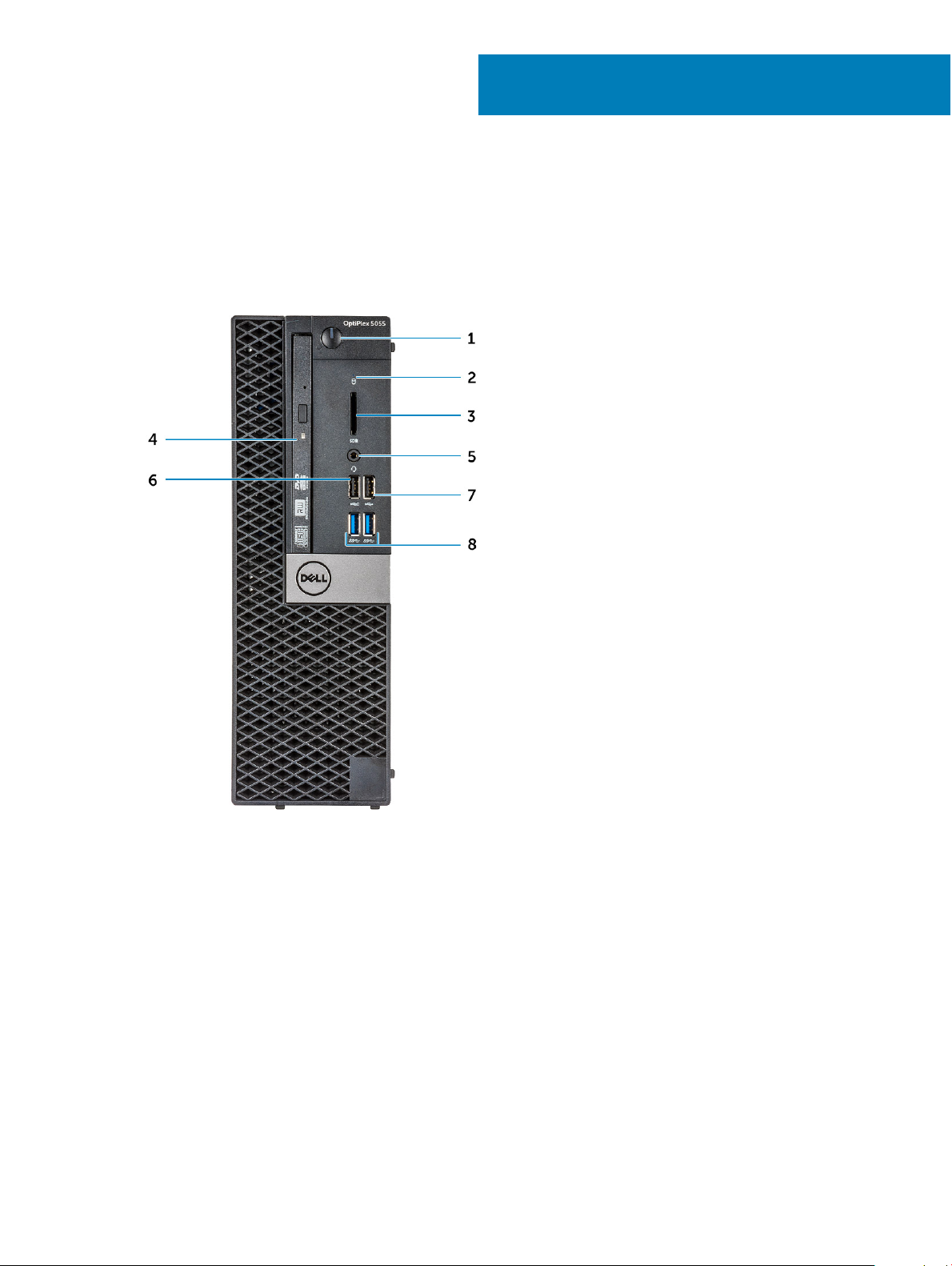
Front chassis view
2
Chassis
1 Power button and power light 2 Hard drive activity light
3 Memory card reader (optional) 4 Optical drive (optional)
5 Headset port 6 USB 2.0 port with PowerShare
7 USB 2.0 port 8 USB 3.1 Gen1 port
8 Chassis
Page 9
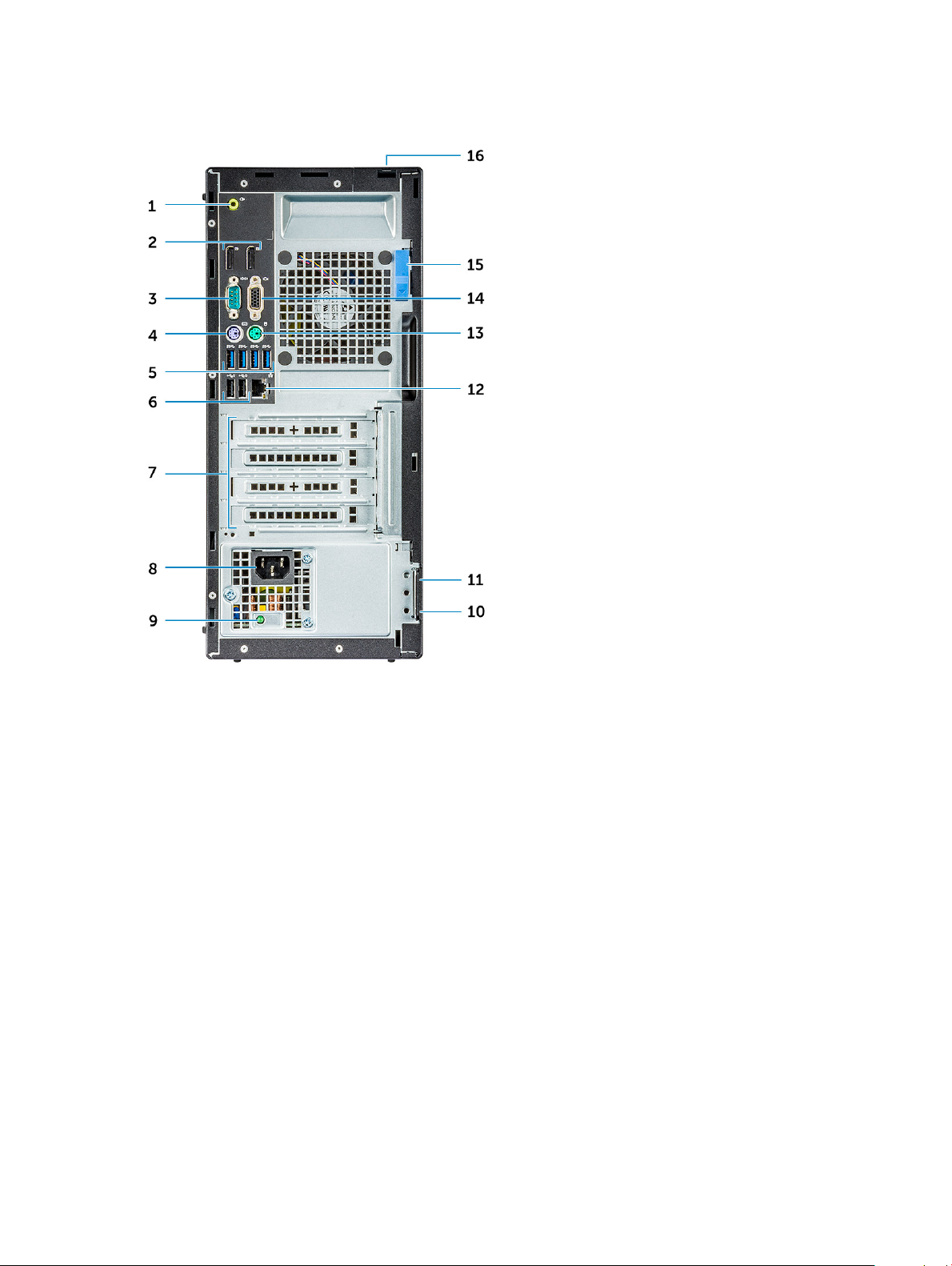
Back chassis view
1 Line-out port 2 DisplayPort
3 Serial port 4 PS/2 keyboard port
5 USB 3.1 Gen1 port 6 USB 2.0 ports (supports Smart Power On)
7 Expansion card slots 8 Power connector port
9 Power supply diagnostic light 10 Padlock ring
11 Kensington security cable slot 12 Network port
13 PS/2 mouse port 14 VGA connector port (optional)
15 Release latch 16 Cable cover lock slot
Chassis 9
Page 10
Disassembly and reassembly
Back cover
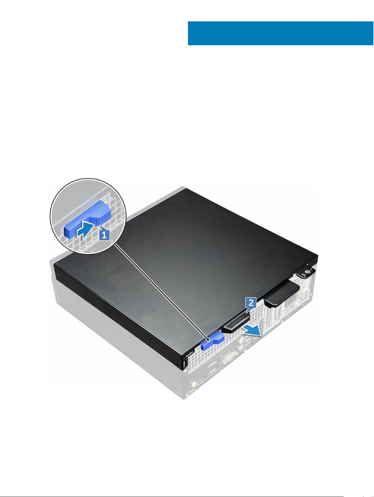
Removing cover
1 Follow the procedure in Before working inside your computer.
2 To release cover:
a Slide the blue retention tab to the right to unlock the cover [1].
b Slide the cover toward the back of the computer [2].
3
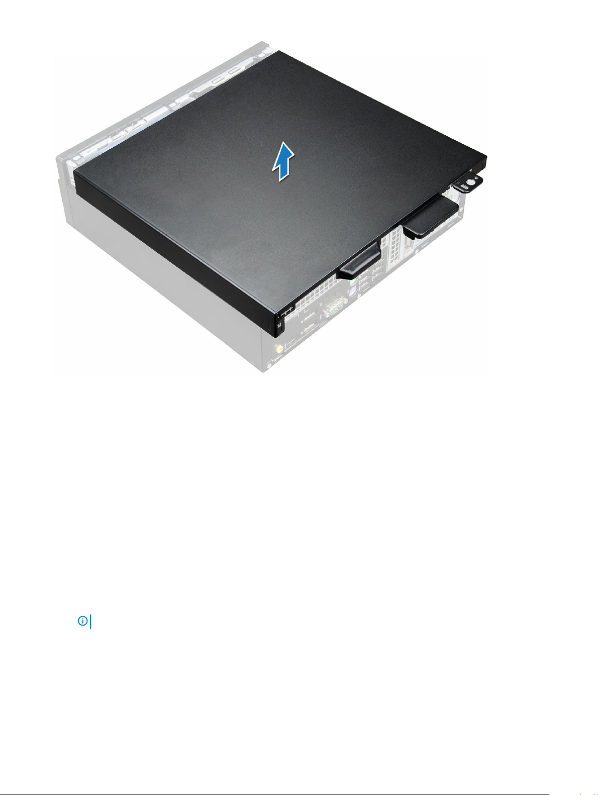
3 Lift the cover to remove it from the computer.
10 Disassembly and reassembly
Page 11
Installing cover
1 Place the cover on the computer and slide the cover forward until it clicks into place.
2 Follow the procedure in After working inside your computer.
Front Bezel
Removing the front bezel
1 Follow the procedure in Before working inside your computer.
2 Remove the cover.
3 To remove front bezel:
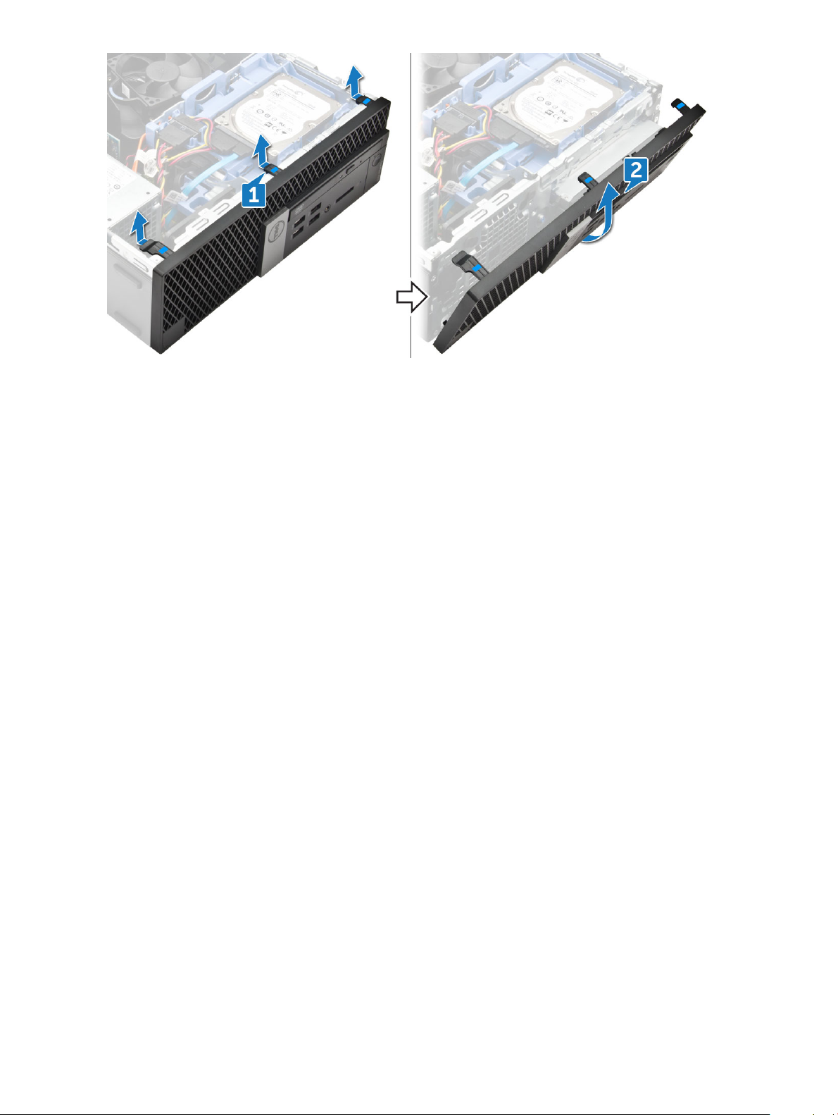
a Lift the tabs to release the bezel from the chassis [1].
b Remove the front bezel from the computer [2].
: Please ensure that the tabs at the bottom of the bezel is also released before lifting the bezel.
NOTE
Disassembly and reassembly 11
Page 12
Installing front bezel
1 Insert the tabs of the bezel into the slots on the chassis.
2 Press the bezel until the tabs click into place.
3 Install the cover.
4 Follow the procedure in After working inside your computer.
Storage device
Removing 2.5–inch hard drive assembly
1 Follow the procedure in Before working inside your computer.
2 Remove the cover.
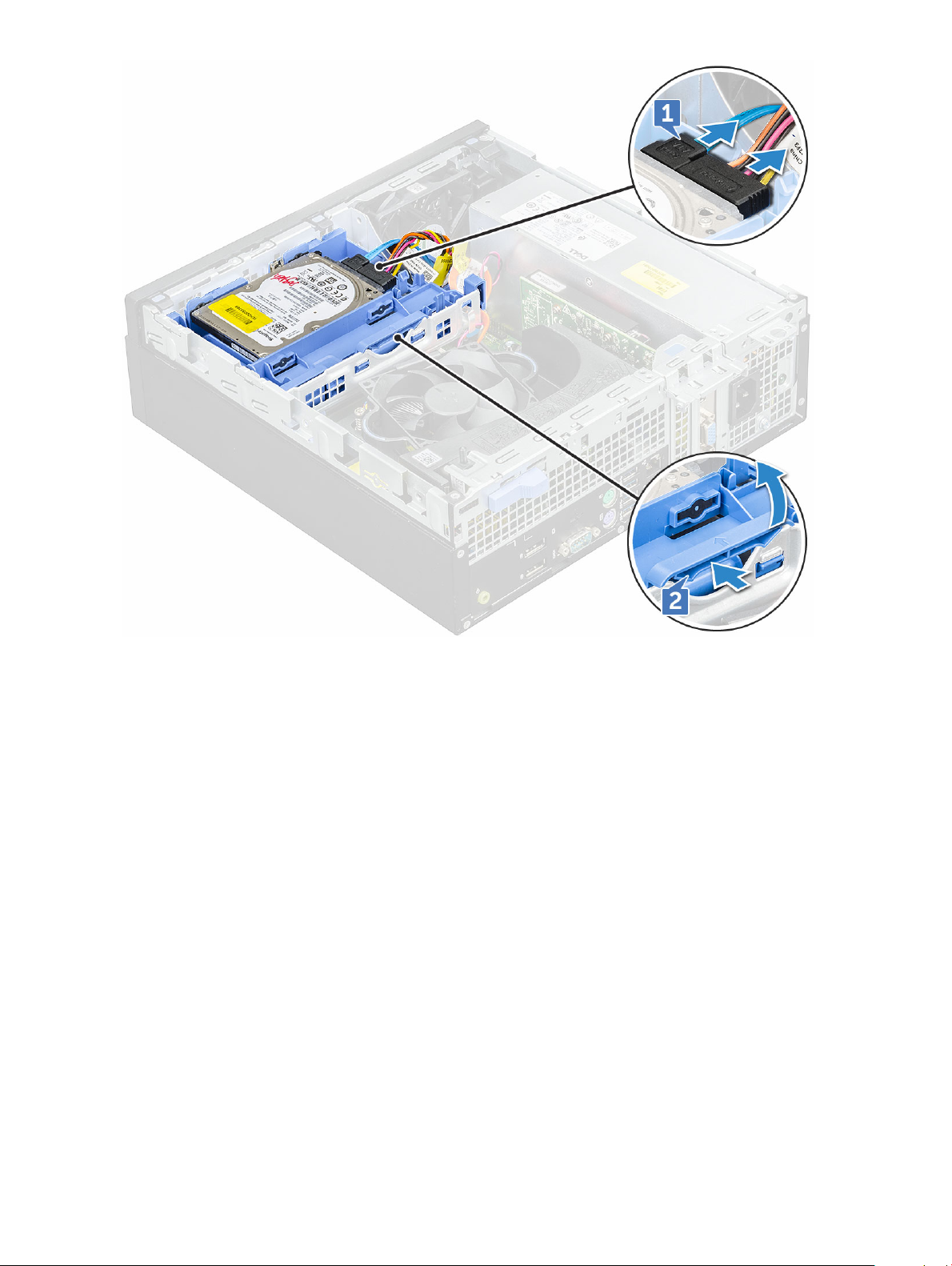
3 To remove the 2.5-inch drive assembly:
a Disconnect the SATA cable and power cable from the drive [1].
b Push the tab to release drive assembly from the chassis [2].
12
Disassembly and reassembly
Page 13
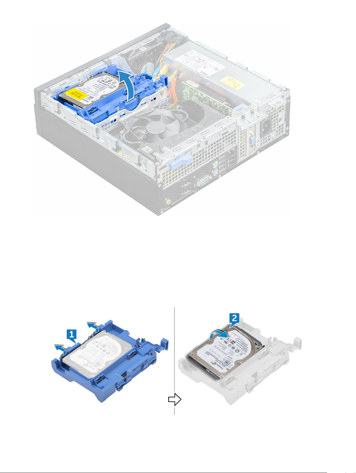
4 Slide and lift the hard drive assembly from the computer.
Disassembly and reassembly
13
Page 14
Removing 2.5–inch hard drive from the hard drive bracket
1 Follow the procedure in Before working inside your computer.
2 Remove the:
a cover
b 2.5 inch hard drive assembly
3 To remove hard drive bracket:
a Pull one side of the hard drive bracket to disengage the pins on the bracket from the slots on the hard drive [1].
b Lift the drive out of the 2.5-inch drive bracket [2].
14
Disassembly and reassembly
Page 15

Installing 2.5–inch hard drive into the hard drive bracket
1 Flex the side of the hard drive bracket, to align and insert the pins on the bracket into the hard drive.
2 Insert the hard drive into the hard drive bracket until it clicks into place.
3 Install the:
a 2.5 inch hard drive assembly
b cover
4 Follow the procedure in After working inside your computer.
Installing 2.5–inch hard drive assembly
1 Insert the drive assembly into the slot on the computer until it clicks into place.
2 Connect the SATA cable and the power cable to the connectors on the hard drive.
3 Install the cover.
4 Follow the procedure in After working inside your computer.
Expansion card
Removing PCIe expansion card
1 Follow the procedure in Before working inside your computer.
2 Remove the:
a cover
b front bezel
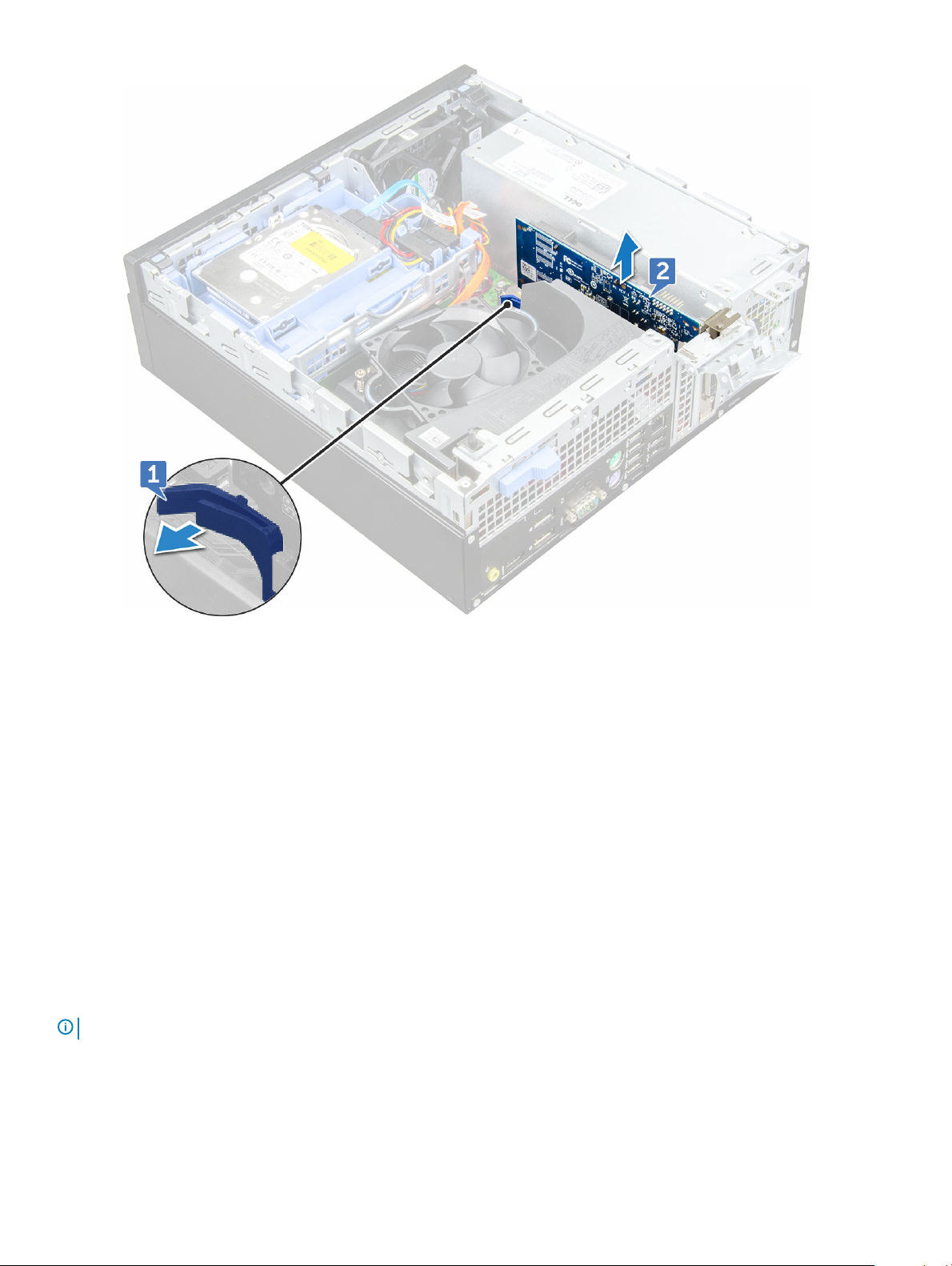
3 Pull the metal tab to open the expansion card latch.
Disassembly and reassembly
15
Page 16
4 To remove the PCIe expansion card:
a Pull the release latch to unlock the PCIe expansion card [1].
b Push the release tab [2] and lift the PCIe expansion card out of the computer [3].
NOTE
: The release tab is at the base of the expansion card.
16 Disassembly and reassembly
Page 17
5 Repeat the steps to remove any additional PCIe expansion cards.
Installing PCIe expansion card
1 Insert the expansion card into the connector on the system board.
2 Press the expansion card until it clicks into place.
3 Close the expansion card latch and press it until it clicks into place.
4 Install the:
a front bezel
b cover
5 Follow the procedure in After working inside your computer.
Cooling shroud
Removing the cooling shroud
NOTE
: Cooling shroud is encompasses the processor assembly and it must be removed to access the processor.
1 Follow the procedure in Before working inside your computer.
2 Remove the cover.
3 To remove cooling shroud:
a Holding the touch points, pull the fan duct bracker outwards to release the cooling shroud.
Disassembly and reassembly
17
Page 18
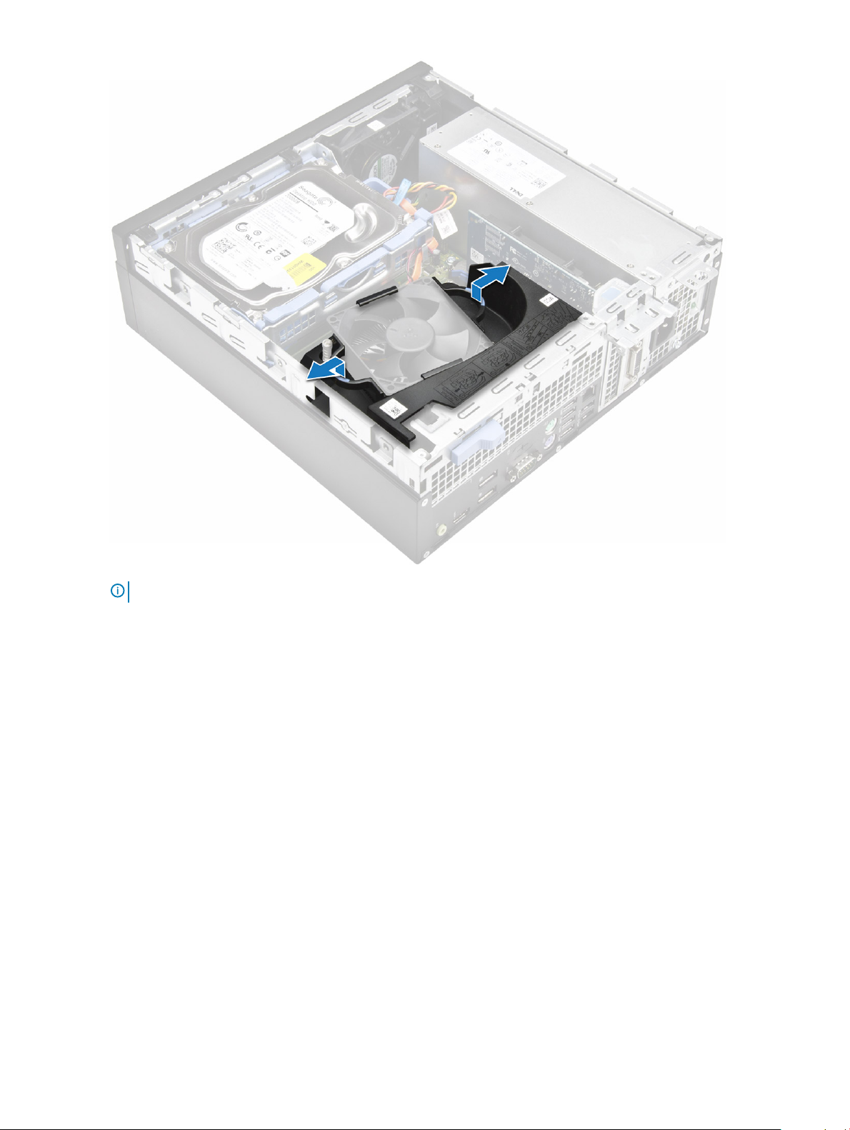
NOTE: Illustration on how to remove the shroud is also given on the shroud.
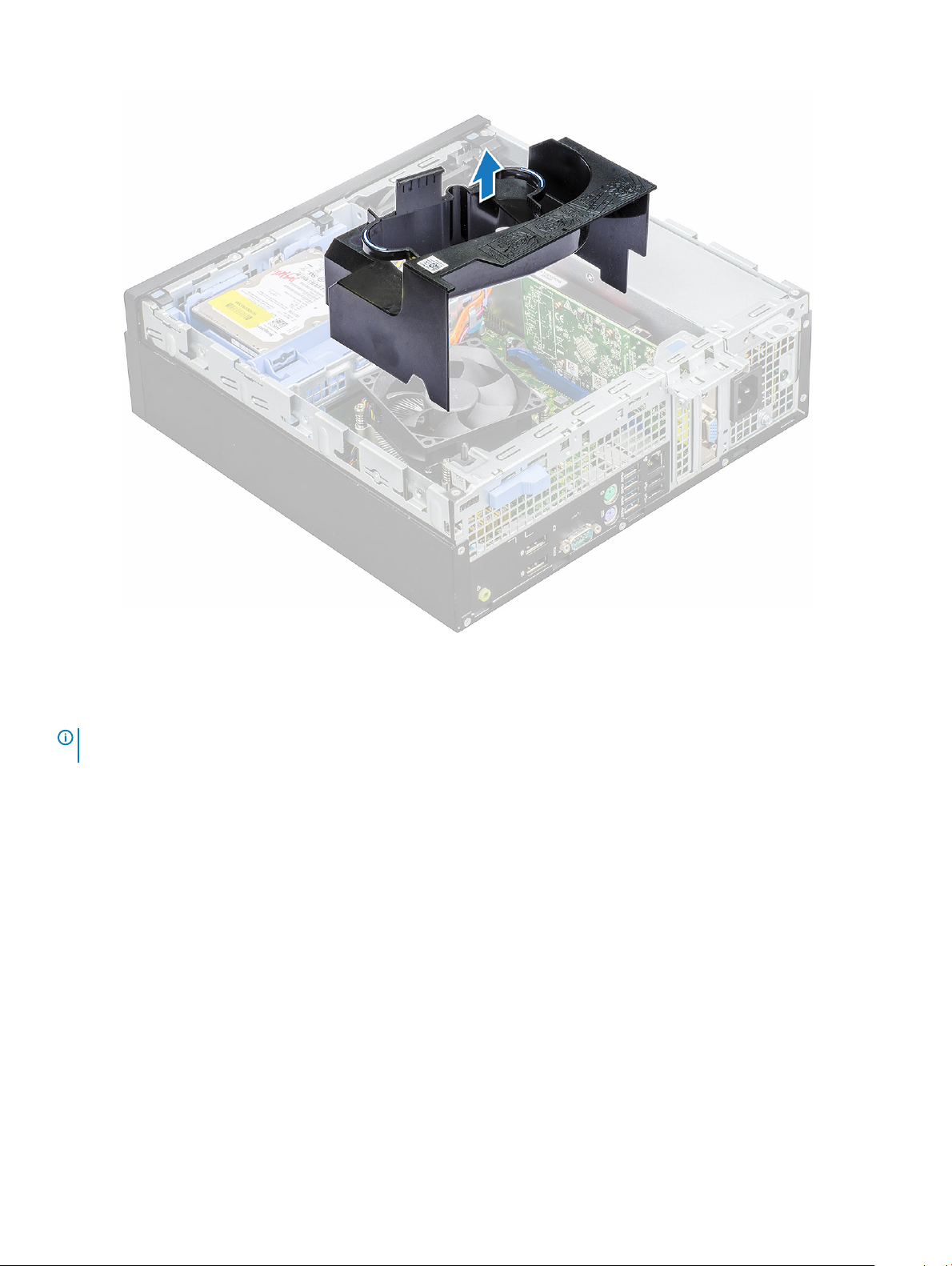
b Lift the cooling shroud away from the chassis.
18
Disassembly and reassembly
Page 19
Installing cooling shroud
: When inserting the shroud on the processor assembly, please ensure that the data and power cables of the optical drive
NOTE
do not get caught inside the shroud.
1 Align the slots on the cooling shroud, with the screws on the heat sink.
2 Insert the cooling shroud over the processor assembly.
3 Install the cover.
4 Follow the procedure in After working inside your computer.
Coin-cell battery
Removing coin cell battery
1 Follow the procedure in Before working inside your computer.
2 Remove the:
a cover
b cooling shroud
c expansion card
3 To remove the coin cell battery:
a Using a plastic scribe press the release latch until the coin cell battery pops out [1].
Disassembly and reassembly
19
Page 20
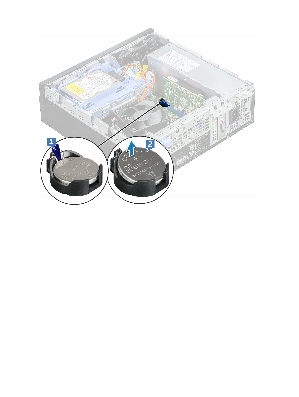
b Remove the coin cell battery from the connector on the system board [2].
Installing coin cell battery
1 Hold the coin cell battery with the "+" sign facing up and slide it under the securing tabs at the positive side of the connector.
2 Press the battery into the connector until it locks into place.
3 Install the:
a expansion card
b cooling shroud
c cover
4 Follow the procedure in After working inside your computer.
Optical drive
Removing optical drive
1 Follow the procedure in Before working inside your computer.
2 Remove the:
a cover
b front bezel
c cooling shroud
Disassembly and reassembly
20
Page 21
d 2.5 inch hard drive assembly
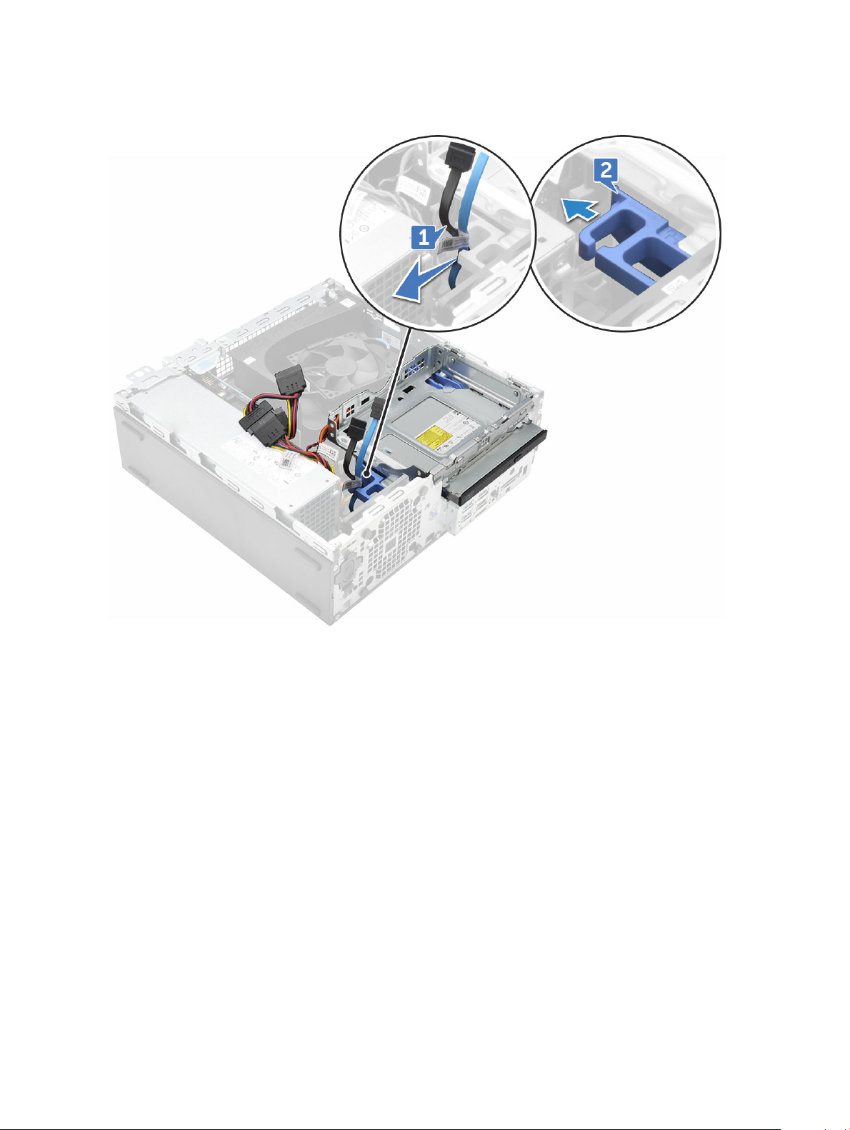
3 To remove optical drive:
a Release the cables from the retention clip [1].
b Slide the blue tab to unlock the optical drive assembly [2].
4 To remove the optical drive assembly:
a Pull the tab upward to release the assembly [1].
b Holding the tab, disconnect the optical drive cables [2].
c Slide and lift the optical drive assembly away from the computer [3].
Disassembly and reassembly
21
Page 22
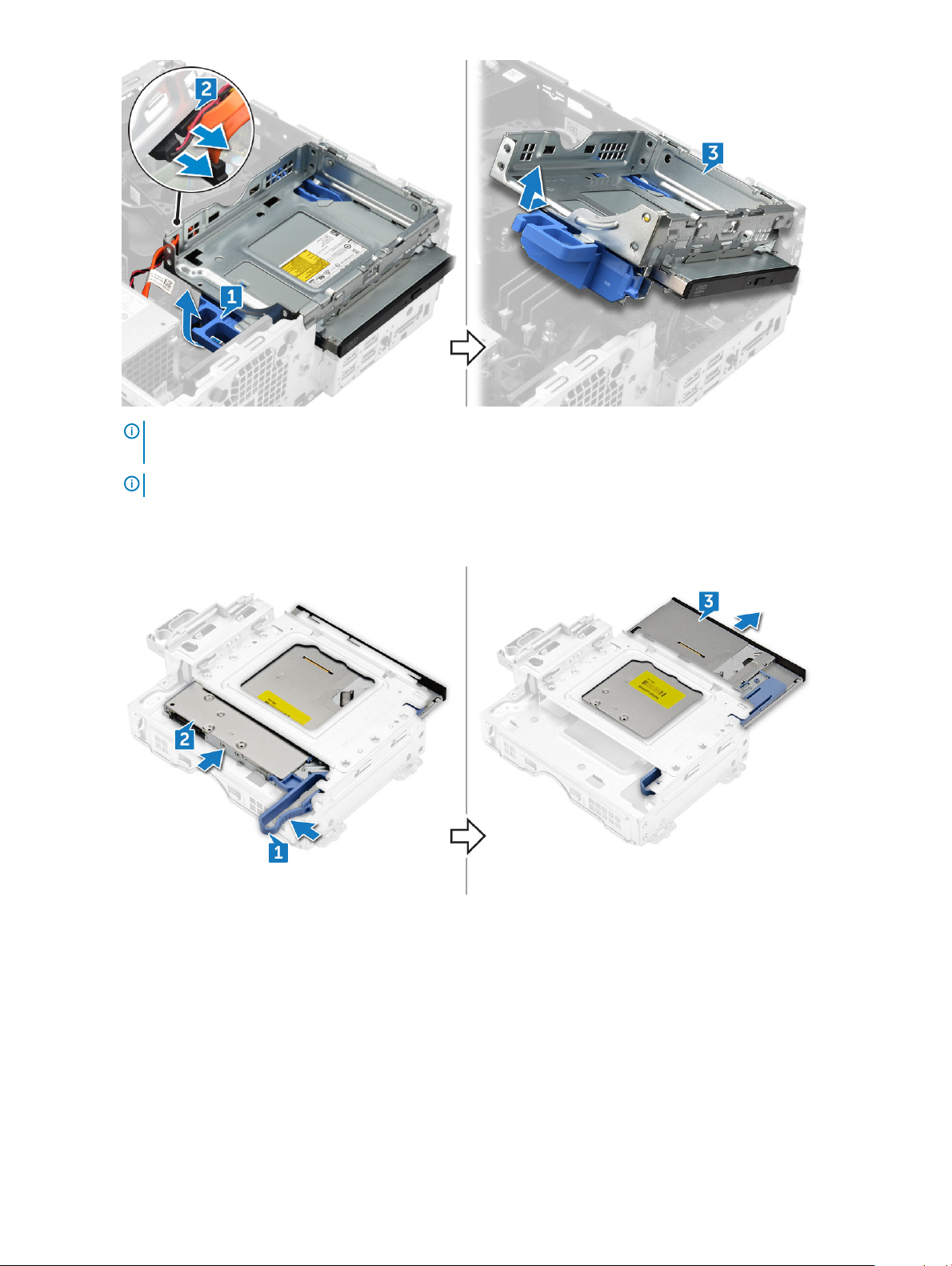
NOTE: After releasing the Optical drive, you can also ip the drive assembly for easy access to the drive
cables.
NOTE: The Optical drive cables are available on side of the drive assembly.
5 To remove the optical drive:
a Slide the tab to release the optical drive [1].
b Push the optical drive away from the assembly [2][3].
Installing optical drive
1 Slide the optical drive into the optical drive assembly.
2 Align the tabs on the optical assembly with the slots on the computer.
3 Lower the optical drive assembly into the computer.
4 Lock the latch to secure the optical drive to the computer.
5 Connect the data and the power cables to the optical drive.
6 Install the:
a 2.5 inch hard drive assembly
Disassembly and reassembly
22
Page 23

b cooling shroud
c front bezel
d cover
7 Follow the procedure in After working inside your computer.
M.2 PCIe SSD
Removing M.2 PCIe SSD
1 Follow the procedure in Before working inside your computer.
2 Remove the:
a cover
b front bezel
c 2.5 inch hard drive assembly
d cooling shroud
e optical drive
3 To remove the M.2 PCIe SSD:
a Pull the blue plastic pin that secures the M.2 PCIe SSD to the system board [1].
b Disconnect the M.2 PCIe SSD from the connector on the system board [2].
Disassembly and reassembly 23
Page 24

Installing M.2 PCIe SSD
1 Insert the M.2 PCIe SSD to the connector
2 Press the blue plastic tab to secure the M.2 PCIe SSD.
3 Install the:
a optical drive
b cooling shroud
c 2.5 inch hard drive assembly
d front bezel
e cover
4 Follow the procedure in After working inside your computer.
Heat sink assembly
Removing heat sink assembly
1 Follow the procedure in Before working inside your computer.
2 Remove the:
a cover
b front bezel
c 2.5 inch hard drive assembly
d cooling shroud
e optical drive
3 To remove the heat sink assembly:
a Disconnect the heat sink assembly cable from the connector on the system board [1].
b Loosen the 6 captive screws that secure the heat sink assembly to the system board [2].
NOTE
: Loosen the screws based on the numbers available on the system board.
c Lift the heat sink assembly away from the computer [3].
24
Disassembly and reassembly
Page 25

Installing heat sink assembly
1 Align the screws of the heat sink assembly with the holders on the system board.
2 Place the heat sink assembly on the processor.
3 Replace the 6 captive screws to secure the heat sink assembly to the system board.
NOTE
: Tighten the screws based on the order given in the system board.
4 Connect the heat sink assembly cable to the connector on the system board.
5 Install the:
a optical drive
b cooling shroud
c 2.5 inch hard drive assembly
d front bezel
e cover
6 Follow the procedure in After working inside your computer.
Processor
Removing the processor
1 Follow the procedure in Before working inside your computer.
2 Remove the:
Disassembly and reassembly
25
Page 26

a cover
b front bezel
c 2.5 hard drive assembly
d cooling shroud
e optical drive
f heat sink assembly
3 To remove the processor:
a Release the socket lever by pushing the lever down and out from under the tab on the processor shield [1].
b Lift the lever upward and lift the processor shield [2].
c Lift the processor out of the socket [3].
CAUTION: Do not touch the processor socket pins, they are fragile and can be permanently damaged. Be careful not
to bend the pins in the processor socket when removing the processor out of the socket.
Installing the processor
1 Align the processor with the socket keys.
CAUTION
socket.
2 Align the pin-1 indicator of the processor with the triangle on the socket.
3 Place the processor on the socket such that the slots on the processor align with the socket keys.
4 Close the processor shield by sliding it under the retention screw.
5 Lower the socket lever and push it under the tab to lock it.
Disassembly and reassembly
26
: Do not use force to seat the processor. When the processor is positioned correctly, it engages easily into the
Page 27

6 Install the:
a heat sink assembly
b optical drive
c cooling shroud
d 2.5 hard drive assembly
e front bezel
f cover
7 Follow the procedure in After working inside your computer.
Intrusion switch
Removing intrusion switch
1 Follow the procedure in Before working inside your computer.
2 Remove the:
a cover
b front bezel
c cooling shroud
3 To the intrusion switch:
a Disconnect the intrusion switch cable from the connector on the system board [1].
b Slide the intrusion switch and push it to remove from the chassis [2].
Disassembly and reassembly
27
Page 28

Installing intrusion switch
1 Insert the intrusion switch into the slot on the computer.
2 Connect the intrusion switch cable to the connector on the system board.
3 Install the:
a cooling shroud
b front bezel
c cover
4 Follow the procedure in After working inside your computer.
Memory modules
Removing memory module
1 Follow the procedure in Before working inside your computer.
2 Remove the:
a cover
b front bezel
c 2.5 inch hard drive assembly
d cooling shroud
e optical drive
3 To remove the memory module:
a Push the tabs on both sides of the memory module.
b Lift the memory module from the connector on the system board.
Installing memory module
1 Align the notch on the memory module with the tab on the memory module connector.
2 Insert the memory module into the memory module socket.
3 Press the memory module until the memory module retention tabs click into place.
4 Close the front panel door.
5 Install the:
a optical drive
b cooling shroud
c 2.5 inch hard drive assembly
d front bezel
e cover
6 Follow the procedure in After working inside your computer.
Disassembly and reassembly
28
Page 29

VGA Daughterboard
Removing the VGA daughter board
1 Follow the procedure in Before Working Inside Your Computer.
2 Remove the:
a Back Cover
b Bezel
3 Open the Front Bezel Door
4 To remove the VGA daughter board:
a Remove the screws that secure the VGA connector to the computer [1].
b Slide the VGA connector to release it from the computer [2].
c Remove the screw that secures the VGA daughter board to the computer [3].
d Lift the VGA daughter board using the handle to remove it from the computer [4].
Installing the VGA daughter board
1 Align the VGA daughter board with the screw holder on the system board.
2 Tighten the screw to secure the VGA daughter board to the system board.
3 Insert the VGA connector into the slot at the back of the computer.
4 Tighten the screws to secure the VGA connector to the computer.
5 Install the:
a Bezel
b Cover
6 Follow the procedure in After Working Inside Your Computer.
SD card
Removing SD card reader
1 Follow the procedure in Before working inside your computer.
2 Remove the:
a cover
b front bezel
c 2.5 inch hard drive assembly
d cooling shroud
e optical drive
f M.2 PCIe SSD
3 To remove the SD card reader:
a Release the power cables from the retention clips on the SD card reader enclosure [1].
b Remove the 6 screws that secure the SD card reader [2].
c Lift the SD card reader away from the computer [3].
Disassembly and reassembly
29
Page 30

Installing SD card reader
1 Place the SD card in the slot on the system board.
2 Tighten the 6 screw to secure the SD card reader to the front panel door.
3 Install the:
a M.2 PCIe SSD
b optical drive
c cooling shroud
d 2.5 inch hard drive assembly
e front bezel
f cover
4 Follow the procedure in After working inside your computer.
Power supply unit
Removing power supply unit — PSU
1 Follow the procedure in Before working inside your computer.
2 Remove the:
a cover
b front bezel
Disassembly and reassembly
30
Page 31

c 2.5 inch hard drive assembly
d cooling shroud
e optical drive
3 To release the PSU:
a Disconnect the PSU cables from the connectors on the system board [1].
b Unroute the PSU cables from the retention clips [2, 3].
4 To disconnect the cables:
a Disconnect the power cable from the system board [1] [2].
b Lift the cables away from the computer [3, 4].
c Remove the 6 screws that secure the PSU to the computer [5].
Disassembly and reassembly
31
Page 32

5 To remove the PSU:
a Press the blue release tab [1]
b Slide the PSU and lift it away from the computer [2].
32
Disassembly and reassembly
Page 33

Installing power supply unit — PSU
1 Insert the PSU into the slot.
2 Slide the PSU towards the back of the computer until it clicks into place.
3 Replace the screws( 6lbs) to secure the PSU to the computer.
4 Route the PSU cables through the retention clips.
5 Connect the PSU cables to the connectors on the system board.
6 Install the:
a optical drive
b cooling shroud
c 2.5 inch hard drive assembly
d front bezel
e cover
7 Follow the procedure in After working inside your computer.
Power switch
Removing power switch
1 Follow the procedure in Before working inside your computer.
2 Remove the:
Disassembly and reassembly
33
Page 34

a cover
b front bezel
c 2.5 inch hard drive assembly
d cooling shroud
e optical drive
3 To release the power switch:
a Disconnect the power switch cable from the system board [1].
b Press the power switch retention tabs and pull out from the computer [2, 3].
Installing power switch
1 Slide the power switch module into the slot on the chassis until it clicks into place.
2 Connect the power switch cable to the connector on the system board.
3 Install the:
a optical drive
b cooling shroud
c 2.5 inch hard drive assembly
d front bezel
Disassembly and reassembly
34
Page 35

e cover
4 Follow the procedure in After working inside your computer.
Speaker
Removing speaker
1 Follow the procedure in Before working inside your computer.
2 Remove the:
a cover
b front bezel
c 2.5 inch hard drive assembly
d cooling shroud
e optical drive
3 To remove the speaker:
a Disconnect the speaker cable from the connector on the system board [1].
b Press the release tabs [2], and slide the speaker module [3] out of the slot.
Installing speaker
1 Insert the speaker into the slot and press it until it clicks into place.
2 Connect the speaker cable to the connector on the system board.
Disassembly and reassembly
35
Page 36

3 Install the:
a optical drive
b cooling shroud
c 2.5 inch hard drive assembly
d front bezel
e cover
4 Follow the procedure in After working inside your computer.
System board
Removing the system board
1 Follow the procedure in Before working inside your computer.
2 Remove the:
a cover
b front bezel
c 2.5 inch hard drive assembly
d cooling shroud
e optical drive
f M.2 PCIe SSD
g heat sink assembly
h memory module
i processor
j expansion card
k SD card
3 Disconnect the following cables from the system board:
a speaker [1]
b 2.5–inch drive [2]
c optical drive [3]
d data cable [4]
36
Disassembly and reassembly
Page 37

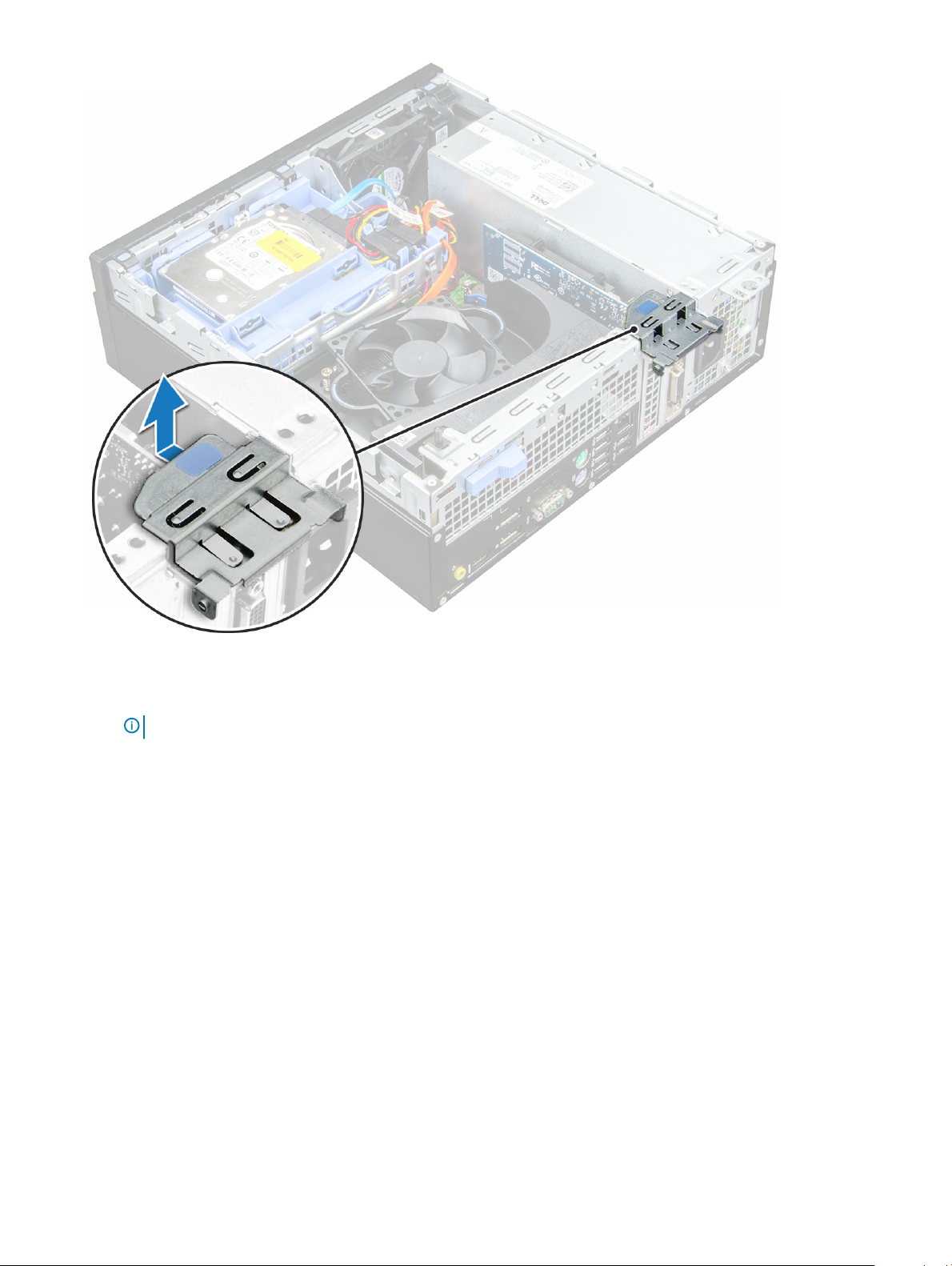
4 Disconnect the following cables and screw from the system board:
a PSU [1]
b hard drive and optical drive caddy stand o screw [2]
c PSU [3]
d power switch [4]
e intrusion switch [5]
Disassembly and reassembly
37
Page 38

5 To remove the I/O panel plate:
a Remove the 6 screw that secures the I/O panel [1].
b Slide and push toward the front from the computer [2].
38
Disassembly and reassembly
Page 39

6 To remove the system board:
a Remove the 12 screws that secure the system board to the computer
b Slide and lift the system board away from the computer [2].
Disassembly and reassembly
39
Page 40

Installing the system board
1 Hold the system board by its edges and align it toward the back of the computer.
2 Lower the system board into the chassis until the connectors at the back of the system board.
3 Align with the slots on the chassis, and the screw holes on the system board align with the standos on the computer.
4 Replace the screws (12 lbs) to secure the system board to the computer.
5 Route all the cables through the routing clips.
6 Align the cables with the pins on connectors on the system board and connect the following cables to the system board:
a intrusion switch
b optical drive
c hard drive
d PSU
e power switch
f power distribution for optical drive and hard drive
7 Install the:
a expansion card
Disassembly and reassembly
40
Page 41

b memory module
c heat sink assembly
d SD card
e M.2 PCIe SSD
f processor
g cooling shroud
h optical drive
i 2.5 inch hard drive assembly
j front bezel
k cover
8 Follow the procedure in After working inside your computer.
System board layout
This chapter explains about the motherboard's layout with name and location of its connectors.
1 PCI-e x16 Connector (SLOT2) 2 PCI-e x4 Connector (SLOT1) - open ended X4 to support
X16
3 VGA Daughter Board Connector (VGA) 4 Processor Socket (CPU)
5 CPU Power Connector (ATX_CPU) 6 Intrusion Switch Connector (INTRUDER)
7 CPU fan Connector (FAN_CPU) 8 Memory Slots (DIMM1,DIMM2,DIMM3,DIMM4)
9 M.2 Slot 3 Connector (M.2_SSD) 10 Power Switch Connector (PWR_SW)
11 Media Card Reader Connector (CARD_READER) 12 System fan Connector (FAN_SYS)
Disassembly and reassembly 41
Page 42

13 SATA2 Connector Black Color (SATA2) 14 SATA0 Connector Blue Color (SATA0)
15 ATX Power Connector (ATX_SYS) 16 Front USB2.0 Connector (Front_USB)
17 HDD&ODD Power Cable Connector (SATA_PWR) 18 Clear CMOS Jumper (CMOS_CLR); Clear Password Jumper
(PASSWORD_CLR); Clear Password ; Jumper
(PASSWORD_CLR); Service Mode Jumper
(SERVICE_MODE)
19 Internal Speaker Connector (INT_SPKR) 20 Internal USB Connector (WF_BT_USB)
21 SATA 1 Connector White Color (SATA1) 22 Battery Connector (BATTERY)
42 Disassembly and reassembly
Page 43

Technology and components
This chapter details the technology and components available in the system.
Topics:
• Systems management features
• In-Band Systems Management – Dell Client Command Suite
• Out-of-Band Systems Management – DASH
• AMD APUs, AMD Ryzen CPUs and APUs
• AMD PT B350
• AMD Radeon R7 M450
• AMD Radeon R5 M430
• USB features
• DDR4
• Active State Power Management
Systems management features
4
Overview: Dell commercial systems come with a number of systems management options that are include by default for In-Band
management with our Dell Client Command Suite. In-Band management meaning that the Operating System is functional and the device is
connected to a network so that it can be managed. The Dell Client Command Suite of tools can be leveraged individually or with a systems
management console like SCCM, LANDESK, KACE, etc.
We also oer Out-of-Band management as an option. Out-of-Band management is when the system does not have a functional operating
system or is turned o and you still want to be able to manage the system in that state.
In-Band Systems Management – Dell Client Command Suite
The Dell Client Command Suite of tools is free to download at http://dell.com/command and can be used with all OptiPlex desktops. It
contains the following components that can be used individually, or in the case of SCCM in conjunction with our integration for SCCM.
Dell Command | Deploy Driver Packs - Bundles of system specic drivers (web hosted on dell.com/command) that have been extracted
and reduced to an OS consumable state for use with any OS deployment tool. Here is a link to Dell TechCenter where you can nd the
driver packs for each commercial client system: http://en.community.dell.com/techcenter/enterprise-client/w/wiki/2065.dell-command-
deploy-driver-packs-forenterprise-client-os-deployment
Dell Command | Congure - A GUI based IT administrator tool for conguring and deploying hardware settings in either a pre-OS or post-
OS environment. Example congurations include enabling TPM, restricting access to USB ports, locking the BIOS with BIOS passwords,
disabling wireless/Bluetooth.
Dell Command | Monitor - A WMI (Windows Management Instrumentation) agent that provides deep hardware inventory and health
monitoring along with command line and scripting capabilities that allow IT administrators to congure their hardware remotely.
Dell Command | Update - a factory-installed application that end-users, with administrative rights, may utilize to individually manage their
own Dell updates. This tool leverages the Updates Catalog for scheduling and installing Dell updates (drivers, BIOS, rmware).
Technology and components 43
Page 44

Dell Command | Update Catalog - Provides searchable metadata that is leveraged with Dell Command | Update and enables management
consoles Dell KACE Appliances, LANDesk Management Systems and Microsoft System Center to retrieve the latest system specic
updates (driver, rmware, or BIOS) for any Dell commercial client to be delivered seamlessly to end-users.
Dell Command | PowerShell Provider - Furthers the ability to standardize on this industry-leading scripting preference by enabling IT
administrators to dynamically query and modify hardware settings with native PowerShell commands.
Dell Command | Power Manager - factory installed on all end-point devices with a battery (laptops, tablets) that enables modications
beyond the power options provided by the operating system.
Dell Command | Integration Suite for System Center 2012 - This suite integrates all the key components of the Client Command Suite
into Microsoft System Center Conguration Manager 2012 and later.
Out-of-Band Systems Management – DASH
DMTF’s Desktop and mobile Architecture for System Hardware (DASH) Standard is a suite of specications that takes full advantage of
DMTF’s Web Services for Management (WS-Management) specication – delivering standards-based web services management for
desktop and mobile client systems. Through DASH, DMTF provides the next generation of standards for secure out-of-band and remote
management of desktop and mobile systems.
OptiPlex 5055 with DASH 1.2 on BCM5762 supports the following features such as remote power command, OOO Firmware Update.
To learn more about DMTF’s DASH, visit DMTF’s website at:https://www.dmtf.org/standards/dash
AMD APUs, AMD Ryzen CPUs and APUs
This topic explains about the AMD's APUs, Ryzen series of CPUs and Ryzen series of APUs.
OptiPlex 5055 is oered with either of the three variants of AMD's A-Series APUs, Ryzen CPUs or APUs.
• Optiplex 5055 A-Series: Oered with AMD Ryzen 7 Pro 1700, Ryzen 5 Pro 1500 and Ryzen 3 Pro 1300.
• Optiplex 5055 Ryzen CPU: Oered with AMD PRO A12-9800, A10-9700, A8-9600, and A6-9500.
• OptiPlex 5055 Ryzen APU: Oered with Ryzen 3 Pro 2200G, Ryzen 5 Pro 2400G and Athlon Pro 200GE.
AMD Advanced Processing Unit - APU
This topic explains AMD's Advanced processing Unit (APU)
The AMD Accelerated Processing Units (APU) are a series of 64-bit microprocessors designed aesthetically by AMD combining the
capabilities of Central Processing Unit (CPU) and Graphical Processing Unit (GPU) on a single die(chip).
Features:
• Heterogeneous System Architecture (HSA): An open-source, cross vendor set of specication allowing the integration of CPU and
GPU on the same bus as CPU cores with coherent memory.
• Power Management: CPU and GPU share same power resources optimizing performance and availability.
• System Architecture Integration: Allows the GPU to be context switched, providing a multitasking environment with smart utilization of
hardware resources across workloads.
• Open CL, C++: Support for Open CL and C++ language extensions.
AMD Ryzen
This topic explains about the AMD's Ryzen series of processors.
AMD's Ryzen is a series of CPUs and APUs based on Zen micro architecture. Zen System On Chip(SoC) design allows the PCIe, SATA, and
USB controllers reside on same chip as CPU's cores.
Features:
Technology and components
44
Page 45

• Performance: Simultaneous multithreading (SMT) to allow execution of two threads per core, increasing the Instruction Per Cycle(IPC)
thus enhancing the processing throughput.
• Power: AMD's Sense MI technology employs sensors across the chip to dynamically scaling the frequency and voltage automatically
dened in processor itself allowing better use of available resources.
• Security and Virtualization: Ryzen oers Secure Memory Encryption(SME) and Secure Encrypted Vitalization(SEV) for real time
memory encryption securing the system from cold boot attacks.
AMD Ryzen APUs
This topic explains AMD's Ryzen series of APUs.
Ryzen APUs are series of APU (CPU+GPU) oered with Vega 8/11 graphics processors. Ryzen APUs are performance enhancements over
the predecessor Ryzen CPUs incorporating the GPU on same chip as CPU cores.
AMD PT B350
AMD B350
• Chipset is perfect for power-users who value exibility and overclocking control, but don't need the maximum PCIe bandwidth required
by multi-GPU congurations.
• AMD Socket AM4 represents the company's new future-proof platform targeting the fastest DDR4 memory.
• With processor-direct SATA and USB connectivity, congurable for real-world exibility, the new AM4 platform takes advantage of the
leading-edge features
Specication
Table 1.
Specication
Specication Details
PCI Express Gen3 Graphics 1x16(AMD Ryzen™)1x8 (A-Series/AMD Athlon™)
USB 3.1 G2 + 3.1 G1 + 2.0 2+6+6
SATA + NVMe 4 + x2 NVMe (or 2 SATA 1 x4 NVMe on AMD Ryzen™ Processor).
SATA Express* (SATA & GPP PCIe G3*) 1
PCI Express® GP x6 Gen2 (plus x2 PCIe Gen3 when no x4 NVMe)
SATA RAID 0,1,10
Dual PCI Express® slots No
Over-clocking Unlocked
AMD Radeon R7 M450
Key Specications
The following table contains the key specications of the AMD Radeon R7 M450:
Technology and components
45
Page 46

Table 2. Key Specications
Specication AMD Radeon R7 M450
Product Line AMD
API Supported DirectX 12 , OpenCL 1.2 , OpenGL 4.3
Clock Speed 925 MHz
Bus Width 128-bit
Memory Clock Speed 1.125 GHz
Technology DDR3 SDRAM
Max External Resolution 1920 x 1080
Interface Type PCI Express 3.0 x16
AMD Radeon R5 M430
The AMD Radeon R5 M430 is an entry level graphics card for laptops. It is based on the older Radeon R5 M330 / M335 or R7 M340.
Key Specications
The following table contains the key specications of the AMD Radeon R5 M430:
Table 3. Key
Specication AMD Radeon R5 M430
Radeon R5 M400 Series Radeon R5 M430
Codename Sun XT
Architecture GCN
Pipelines 320 - unied
Memory Bus Width 64 Bit
Shared Memory No
Technology 28 nm
DirectX DirectX 12
Specications
USB features
Universal Serial Bus, or USB, was introduced in 1996. It dramatically simplied the connection between host computers and peripheral
devices like mice, keyboards, external drivers, and printers.
Let's take a quick look on the USB evolution referencing to the table below.
Technology and components
46
Page 47

Table 4. USB evolution
Type Data Transfer Rate Category Introduction Year
USB 3.0/USB 3.1 Gen 2 5 Gbps Super Speed 2010
USB 2.0 480 Mbps High Speed 2000
USB 3.1 Gen 1 (SuperSpeed USB)
For years, the USB 2.0 has been rmly entrenched as the de facto interface standard in the PC world with about 6 billion devices sold, and
yet the need for more speed grows by ever faster computing hardware and ever greater bandwidth demands. The USB 3.1 Gen 1 nally has
the answer to the consumers' demands with a theoretically 10 times faster than its predecessor. In a nutshell, USB 3.1 Gen 1 features are as
follows:
• Higher transfer rates (up to 5 Gbps)
• Increased maximum bus power and increased device current draw to better accommodate power-hungry devices
• New power management features
• Full-duplex data transfers and support for new transfer types
• Backward USB 2.0 compatibility
• New connectors and cable
The topics below cover some of the most commonly asked questions regarding USB 3.1 Gen 1.
Speed
Currently, there are 3 speed modes dened by the latest USB 3.1 Gen 1 specication. They are Super-Speed, Hi-Speed and Full-Speed. The
new SuperSpeed mode has a transfer rate of 4.8Gbps. While the specication retains Hi-Speed, and Full-Speed USB mode, commonly
known as USB 2.0 and 1.1 respectively, the slower modes still operate at 480Mbps and 12Mbps respectively and are kept to maintain
backward compatibility.
USB 3.1 Gen 1 achieves the much higher performance by the technical changes below:
• An additional physical bus that is added in parallel with the existing USB 2.0 bus (refer to the picture below).
• USB 2.0 previously had four wires (power, ground, and a pair for dierential data); USB 3.1 Gen 1 adds four more for two pairs of
dierential signals (receive and transmit) for a combined total of eight connections in the connectors and cabling.
• USB 3.1 Gen 1 utilizes the bidirectional data interface, rather than USB 2.0's half-duplex arrangement. This gives a 10-fold increase in
theoretical bandwidth.
Technology and components
47
Page 48

With today's ever increasing demands placed on data transfers with high-denition video content, terabyte storage devices, high megapixel
count digital cameras etc., USB 2.0 may not be fast enough. Furthermore, no USB 2.0 connection could ever come close to the 480Mbps
theoretical maximum throughput, making data transfer at around 320Mbps (40MB/s) — the actual real-world maximum. Similarly, USB 3.1
Gen 1 connections will never achieve 4.8Gbps. We will likely see a real-world maximum rate of 400MB/s with overheads. At this speed, USB
3.1 Gen 1 is a 10x improvement over USB 2.0.
Applications
USB 3.1 Gen 1 opens up the laneways and provides more headroom for devices to deliver a better overall experience. Where USB video was
barely tolerable previously (both from a maximum resolution, latency, and video compression perspective), it's easy to imagine that with
5-10 times the bandwidth available, USB video solutions should work that much better. Single-link DVI requires almost 2Gbps throughput.
Where 480Mbps was limiting, 5Gbps is more than promising. With its promised 4.8Gbps speed, the standard will nd its way into some
products that previously weren't USB territory, like external RAID storage systems.
Listed below are some of the available SuperSpeed USB 3.1 Gen 1 products:
• External Desktop USB 3.1 Gen 1 Hard Drives
• Portable USB 3.1 Gen 1 Hard Drives
• USB 3.1 Gen 1 Drive Docks & Adapters
• USB 3.1 Gen 1 Flash Drives & Readers
• USB 3.1 Gen 1 Solid-state Drives
• USB 3.1 Gen 1 RAIDs
• Optical Media Drives
• Multimedia Devices
• Networking
• USB 3.1 Gen 1 Adapter Cards & Hubs
Compatibility
The good news is that USB 3.1 Gen 1 has been carefully planned from the start to peacefully co-exist with USB 2.0. First of all, while USB
3.1 Gen 1 species new physical connections and thus new cables to take advantage of the higher speed capability of the new protocol, the
connector itself remains the same rectangular shape with the four USB 2.0 contacts in the exact same location as before. Five new
connections to carry receive and transmitted data independently are present on USB 3.1 Gen 1 cables and only come into contact when
connected to a proper SuperSpeed USB connection.
Windows 8/10 will be bringing native support for USB 3.1 Gen 1 controllers. This is in contrast to previous versions of Windows, which
continue to require separate drivers for USB 3.1 Gen 1 controllers.
Technology and components
48
Page 49

Microsoft announced that Windows 7 would have USB 3.1 Gen 1 support, perhaps not on its immediate release, but in a subsequent Service
Pack or update. It is not out of the question to think that following a successful release of USB 3.1 Gen 1 support in Windows 7, SuperSpeed
support would trickle down to Vista. Microsoft has conrmed this by stating that most of their partners share the opinion that Vista should
also support USB 3.1 Gen 1.
Super-Speed support for Windows XP is unknown at this point. Given that XP is a seven-year-old operating system, the likelihood of this
happening is remote.
DDR4
DDR4 (double data rate fourth generation) memory is a higher-speed successor to the DDR2 and DDR3 technologies and allows up to 512
GB in capacity, compared to the DDR3's maximum of 128 GB per DIMM. DDR4 synchronous dynamic random-access memory is keyed
dierently from both SDRAM and DDR to prevent the user from installing the wrong type of memory into the system.
DDR4 needs 20 percent less or just 1.2 volts, compared to DDR3 which requires 1.5 volts of electrical power to operate. DDR4 also supports
a new, deep power-down mode that allows the host device to go into standby without needing to refresh its memory. Deep power-down
mode is expected to reduce standby power consumption by 40 to 50 percent.
DDR4 Details
There are subtle dierences between DDR3 and DDR4 memory modules, as listed below.
Key notch dierence
The key notch on a DDR4 module is in a dierent location from the key notch on a DDR3 module. Both notches are on the insertion edge
but the notch location on the DDR4 is slightly dierent, to prevent the module from being installed into an incompatible board or platform.
Figure 1. Notch dierence
Increased thickness
DDR4 modules are slightly thicker than DDR3, to accommodate more signal layers.
Figure 2. Thickness dierence
Curved edge
DDR4 modules feature a curved edge to help with insertion and alleviate stress on the PCB during memory installation.
Technology and components
49
Page 50

Figure 3. Curved edge
Memory Errors
Memory errors on the system display the new ON-FLASH-FLASH or ON-FLASH-ON failure code. If all memory fails, the LCD does not
turn on. Troubleshoot for possible memory failure by trying known good memory modules in the memory connectors on the bottom of the
system or under the keyboard, as in some portable systems.
Active State Power Management
This section describes about the Active State Power Management (ASPM).
ASPM is the power management capability of hardware to eectively reduce usage of power by placing the PCI Express(PCIe) based
serial link devices to low-power state when not in use.
ASPM is controlled by BIOS or the power management component of the operating system in two congurations.
• Disabled: PCIe devices operate on high-performance mode.
• L1 Mode: Bi-directional setting of the serially linked PCIe device to low-power state.
NOTE
: This mode provides with higher power saving at expense of latency when re-establishing the connection.
The PCIe bus must be woken up from low-power mode to re-establish the connection with the device. This accounts for the latency, which
is also referred to as ASPM exit latency.
50
Technology and components
Page 51

System setup
System setup enables you to manage your desktop hardware and specify BIOS level options. From the System setup, you can:
• Change the NVRAM settings after you add or remove hardware
• View the system hardware conguration
• Enable or disable integrated devices
• Set performance and power management thresholds
• Manage your computer security
Topics:
• Boot menu
• System Setup options
• Updating the BIOS in Windows
• Updating the Dell BIOS in Linux and Ubuntu environments
• Flashing the BIOS from the F12 One-Time boot menu
• Specications
5
Boot menu
Press <F12> when the Dell™ logo appears to initiate a one-time boot menu with a list of the valid boot devices for the system. Diagnostics
and BIOS Setup options are also included in this menu. The devices listed on the boot menu depend on the bootable devices in the system.
This menu is useful when you are attempting to boot to a particular device or to bring up the diagnostics for the system. Using the boot
menu does not make any changes to the boot order stored in the BIOS.
The options are:
• Legacy Boot:
– Internal HDD
– Onboard NIC
• UEFI Boot:
– Windows Boot Manager
• Other Options:
– BIOS Setup
– BIOS Flash Update
– Diagnostics
– Change Boot Mode Settings
System Setup options
NOTE
: Depending on the computer and its installed devices, the items listed in this section may or may not appear.
System setup 51
Page 52

Table 5. General
Option Description
System Information Displays the following information:
• System Information: Displays BIOS Version, Service Tag, Asset Tag, Ownership Tag, Ownership
Date, Manufacture Date, Express Service Code and the Singed Firmware Update.
• Memory Information: Displays Memory Installed, Memory Available, Memory Speed, Memory
Channel Mode, Memory Technology, DIMM 1 Size, DIMM 2 Size, DIMM 3 Size and DIMM 4
Size.
• PCI Information: Displays SLOT1_M.2, SLOT2_M.2
• Processor Information: Displays Processor Type, Core Count, Current Clock Speed, Minimum
Clock Speed, Maximum Clock Speed, Processor L2 Cache, Processor L3 Cache, HT Capable,
and 64-Bit Technology.
• Device Information: Displays LOM MAC Address, Video Controller, Audio Controller.
Boot Sequence
Advanced Boot Options Allows you to select the Enable Legacy Option ROMs option. By default, this option is selected.
BIOS Setup Advanced Mode Allows you to select BIOS Setup Advanced Mode. By default, this option is selected.
Date/Time Allows you to set the date and time settings. Changes to the system date and time take eect
Table 6. System Conguration
• Boot Mode
• Boot List option:
– Legacy
– UEFI (Default)
• Enable Boot Devices
• Boot Sequence
– Add Boot Option
– Remove Boot Option
– View Boot Option
• Enabled(selected by default)
• Disabled
• Enabled(selected by default)
• Disabled
immediately.
Option Description
Integrated NIC Allows you to control the on-board LAN controller. The option ‘Enable UEFI Network Stack’ is not
selected by default. The options are:
• Disabled
• Enabled
• Enabled w/PXE (default)
NOTE: Depending on the computer and its installed devices, the items listed in this section
may or may not appear.
Serial Port The options are:
• COM1 (Enabled by default)
• COM2 (Disabled by default)
• COM3 (Disabled by default)
52 System setup
Page 53

Option Description
• COM4 (Disabled by default)
SATA Operation Allows you to congure the operating mode of the integrated hard drive controller.
• Disabled = The SATA controllers are hidden
• AHCI (Enabled by default)
• RAID ON = SATA is congured to support RAID mode (Disabled by default)
Drives Allows you to enable or disable the various drives on-board:
• SATA-0 (enabled by default)
• SATA-1
• SATA-2
• SATA-3
• M.2 PCIe SSD-0
Smart Reporting This eld controls whether hard drive errors for integrated drives are reported during system startup.
The Enable Smart Reporting option is disabled by default.
USB Conguration Allows you to enable or disable the integrated USB controller for:
• Enable Boot Support
• Enable Front USB Ports
• Enable Rear USB Ports
All the options are enabled by default.
USB PowerShare This option allows you to charge the external devices, such as mobile phones, music player. This
option is disabled by default.
Audio Allows you to enable or disable the integrated audio controller. The option Enable Audio is selected by
default.
• Enable Microphone
• Enable Audio
• Enable Internal Speaker
The options are selected by default.
Miscellaneous Devices Allows you to enable or disable the Miscellaneous Devices. The option are
• Enable Secure Digital (SD) Card (Enabled by default)
• Secure Digital (SD) Card Read-Only mode
Table 7. Video
Option Description
Multi-Display The option is selected by default.
Primary Display Allows you to select the primary display when multiple controllers are available in the system.
• Auto (default)
• Integrated Graphics
NOTE: If you do not select Auto, the on-board graphics device will be present and enabled.
System setup 53
Page 54

Table 8. Security
Option Description
Admin Password Allows you to set, change, and delete the admin password.
System Password Allows you to set, change, and delete the system password.
Internal HDD-0 Password Allows you to set, change, and delete the computer’s internal HDD.
Internal HDD-1 Password Allows you to set, change, and delete the computer’s internal HDD.
Internal HDD-2 Password Allows you to set, change, and delete the computer’s internal HDD.
Strong Password This option lets you enable or disable strong passwords for the system.
Password Conguration Allows you to control the minimum and maximum number of characters allowed for a administrative
password and the system password. The range of characters is between 4 and 32.
Password Change This option lets you determine whether changes to the System and Hard Disk passwords are
permitted when an administrator password is set.
Allow Non-Admin Password Changes - This option is enabled by default.
UEFI Capsule Firmware Updates This option controls whether this system allows BIOS updates via UEFI capsule update packages.
This option is selected by default. Disabling this option will block BIOS updates from services such as
Microsoft Windows Update and Linux Vendor Firmware Service (LVFS)
TPM 2.0 Security Allows you to control whether the Trusted Platform Module (TPM) is visible to the operating system.
• TPM On (default)
– PPI Bypass for Enable Commands
– PPI Bypass for Disable Commands
– PPI Bypass for Clear Commands
– Attestation Enable (default)
– Key Storage Enable (default)
– SHA-256 (default)
• Clear
• TPM State
– Disable
– Enable (default)
Computrace This eld lets you Activate or Disable the BIOS module interface of the optional Computrace Service
from Absolute Software. Enables or disables the optional Computrace service designed for asset
management.
• Deactivate - This option is selected by default.
• Disable
• Activate
Chassis Intrusion The options are:
• Disable (default)
• Enable
• On-Silent
Admin Setup Lockout Allows you to enable or disable the option to enter Setup when an Administrative password is set.
This option is not set by default.
Table 9. Secure Boot
Option Description
Secure Boot Enable Allows you to enable or disable Secure Boot feature
54 System setup
Page 55

Option Description
• Disable (selected by default)
• Enable
Expert key Management Allows you to manipulate the security key databases only if the system is in Custom Mode. The
Enable Custom Mode option is disabled by default. The options are:
• PK (default)
• KEK
• db
• dbx
If you enable the Custom Mode, the relevant options for PK, KEK, db, and dbx appear. The
options are:
• Save to File- Saves the key to a user-selected le
• Replace from File- Replaces the current key with a key from a user-selected le
• Append from File- Adds a key to the current database from a user-selected le
• Delete- Deletes the selected key
• Reset All Keys- Resets to default setting
• Delete All Keys- Deletes all the keys
NOTE: If you disable the Custom Mode, all the changes made will be erased and the
keys will restore to default settings.
Table 10. Performance
Option Description
C States Control Allows you to enable or disable additional processor sleep states.
This option is enabled by default.
AMD TurboCore Technology This options is disable by default.
Table 11. Power Management
Option Description
AC Recovery Determines how the system responds when AC power is re-applied after a power loss. You can set
the AC Recovery to:
• Power O
• Power On
• Last Power State
This option is Power O by default.
Auto On Time Sets time to automatically turn on the computer. Time is kept in standard 12-hour format
(hour:minutes:seconds). Change the startup time by typing the values in the time and AM/PM elds.
NOTE: This feature does not work if you turn o your computer using the switch on a
power strip or surge protector or if Auto Power is set to disabled.
Deep Sleep Control Allows you to dene the controls when Deep Sleep is enabled.
• Disabled
• Enabled in S5 only
• Enabled in S4 and S5
This option is Enabled in S4 and S5 by default.
System setup 55
Page 56

Option Description
Fan Control Override Allows you to determine the speed of the system fan. When this option is enabled, the system fan
runs at the maximum speed. This option is disabled by default.
USB Wake Support Allows you to enable the USB devices to wake the computer from standby mode. The option "Enable
USB Wake Support" is selected by default
Wake on LAN/WWAN This option allows the computer to power up from the o state when triggered by a special LAN
signal. This feature only works when the computer is connected to AC power supply.
• Disabled - Does not allows the system to power on by special LAN signals when it receives a
wake-up signal from the LAN or wireless LAN.
• LAN - Allows the system to be powered on by special LAN signals.
• WLAN Only - Allows the system to be powered on by special WLAN signals.
• LAN or WLAN- Allows the system to be powered on by special LAN signals or WLAN signals.
• LAN with PXE Boot - A wakeup packet sent to the system in either the S4 or S5 state, that will
cause the system to wake-up and immediately boot to PXE.
This option is Disabled by default.
Block Sleep Allows you to block entering to sleep (S3 state) in OS environment. This option is disabled by default.
Table 12. POST Behavior
Option Description
Numlock LED Allows you to enable or disable the Numlock feature when your computer starts. This option is
enabled by default.
Keyboard Errors Allows you to enable or disable the keyboard error reporting when the computer starts. This option is
enabled by default.
Warnings and Errors This option can speed up the boot process by bypassing some compatibility steps:
• Prompt on Warnings and Errors (enabled by default)
• Continue on Warnings
• Continue on Warnings and Errors
Extend BIOS POST Time The options are:
• 0 seconds (default)
• 5 seconds
• 10 seconds
Full Screen Logo This options is disabled by default.
Table 13. Virtualization Support
Option Description
AMD-V Technology This option is enabled by default.
AMD-VI Technology This option is enabled by default.
Table 14. Maintenance
Option Description
Service Tag Displays the Service Tag of your computer.
Asset Tag Allows you to create a system asset tag if an asset tag is not already set. This option is set by default.
56 System setup
Page 57

Option Description
SERR Messages Controls the SERR message mechanism. This option is set by default. Some graphics cards require
that the SERR message mechanism be disabled.
Dell Development Conguration This options is disabled by default.
BIOS Downgrade Allows you to control ashing of the system rmware to the previous versions. This option is enabled
by default.
NOTE: If this option is not selected, the ashing of the system rmware to the previous
versions is blocked.
Data Wipe Allows you to securely erase the data from all the available internal storages, such as HDD, SSD,
mSATA, and eMMC. The option Wipe on Next Boot is disabled by default.
BIOS recovery Allows you to recover the corrupted BIOS conditions from the recovery les on the primary hard
drive. The option BIOS Recovery from Hard Driveis selected by default
Table 15. System Logs
Option Description
BIOS Events Displays the system event log and allows you to:
• Clear Log
• Mark all Entries
Table 16. SupportAssist System Resolution
Option Description
Auto OS Recovery Threshold Options are: OFF, 1, 2 (default), 3.
Updating the BIOS in Windows
It is recommended to update your BIOS (System Setup), when you replace the system board or if an update is available.
: If BitLocker is enabled, it must be suspended prior to updating the system BIOS, and then re-enabled after the BIOS
NOTE
update is completed.
1 Restart the computer.
2 Go to Dell.com/support.
• Enter the Service Tag or Express Service Code and click Submit.
• Click Detect Product and follow the instructions on screen.
3 If you are unable to detect or nd the Service Tag, click Choose from all products.
4 Choose the Products category from the list.
NOTE
: Choose the appropriate category to reach the product page
5 Select your computer model and the Product Support page of your computer appears.
6 Click Get drivers and click Drivers and Downloads.
The Drivers and Downloads section opens.
7 Click Find it myself.
8 Click BIOS to view the BIOS versions.
9 Identify the latest BIOS le and click Download.
10 Select your preferred download method in the Please select your download method below window, click Download File.
The File Download window appears.
11 Click Save to save the le on your computer.
12 Click Run to install the updated BIOS settings on your computer.
System setup
57
Page 58

Follow the instructions on the screen.
Updating BIOS on systems with BitLocker enabled
CAUTION: If BitLocker is not suspended before updating the BIOS, the next time you reboot the system it will not recognize the
BitLocker key. You will then be prompted to enter the recovery key to progress and the system will ask for this on each reboot. If
the recovery key is not known this can result in data loss or an unnecessary operating system re-install. For more information on
this subject, see Knowledge Article: http://www.dell.com/support/article/sln153694
Updating your system BIOS using a USB ash drive
If the system cannot load into Windows but there is still a need to update the BIOS, download the BIOS le using another system and save
it to a bootable USB Flash Drive.
NOTE: You will need to use a bootable USB Flash drive. Please refer to the following article for further details: http://
www.dell.com/support/article/sln143196
1 Download the BIOS update .EXE le to another system.
2 Copy the le e.g. O9010A12.EXE onto the bootable USB Flash drive.
3 Insert the USB Flash drive into the system that requires the BIOS update.
4 Restart the system and press F12 when the Dell Splash logo appears to display the One Time Boot Menu.
5 Using arrow keys, select USB Storage Device and click Return.
6 The system will boot to a Diag C:\> prompt.
7 Run the le by typing the full lename e.g. O9010A12.exe and press Return.
8 The BIOS Update Utility will load, follow the instructions on screen.
Figure 4. DOS BIOS Update Screen
Updating the Dell BIOS in Linux and Ubuntu environments
If you want to update the system BIOS in a Linux environment such as Ubuntu, see http://www.dell.com/support/article/sln171755.
System setup
58
Page 59

Flashing the BIOS from the F12 One-Time boot menu
Updating your system BIOS using a BIOS update .exe le copied to a FAT32 USB key and booting from the F12 one time boot menu.
BIOS Update
You can run the BIOS update le from Windows using a bootable USB key or you can also update the BIOS from the F12 One-Time boot
menu on the system.
Most Dell systems built after 2012 have this capability and you can conrm by booting your system to the F12 One-Time Boot Menu to see
if BIOS FLASH UPDATE is listed as a boot option for your system. If the option is listed, then the BIOS supports this BIOS update option.
NOTE: Only systems with BIOS Flash Update option in the F12 One-Time Boot Menu can use this function.
Updating from the One-Time Boot Menu
To update your BIOS from the F12 One-Time boot menu, you will need:
• USB key formatted to the FAT32 le system (key does not have to be bootable)
• BIOS executable le that you downloaded from the Dell Support website and copied to the root of the USB key
• AC power adapter connected to the system
• Functional system battery to ash the BIOS
Perform the following steps to execute the BIOS update ash process from the F12 menu:
CAUTION: Do not power o the system during the BIOS update process. Powering o the system could make the system fail to
boot.
1 From a power o state, insert the USB key where you copied the ash into a USB port of the system .
2 Power on the system and press the F12 key to access the One-Time Boot Menu, Highlight BIOS Flash Update using the arrow keys
then press
Enter.
3 The Bios ash menu will open then click the browse button.
System setup
59
Page 60

4 The E5450A14.exe le is shown as an example in the following screenshot. The actual le name may vary.
5 Once the le is selected, it will show in the le selection box and you can click the OK button to continue.
60
System setup
Page 61

6 Click the Begin Flash Update button.
7 A warning box is displayed asking you if you want to proceed. Click the Yes button to begin the ash.
System setup
61
Page 62

8 At this point the BIOS ash will execute, the system will reboot and then the BIOS ash will start and a progress bar will show the
progress of the ash. Depending on the changes included in the update, the progress bar may go from zero to 100 multiple times and
the ash process could take as long as 10 minutes. Generally this process takes two to three minutes.
9 Once complete, the system will reboot and the BIOS update process is completed.
Specications
: Oerings may vary by region. For more information regarding the conguration of your computer in:
NOTE
• Windows 10, click or tap Start > Settings > System > About.
62 System setup
Page 63

Table 17. Chipset
Feature Specication
Chipset AMD PT B350 Chipset
Table 18. Processor
Feature Specication
Processor type
Total cache Up to 4MB
Table 19. Memory
Feature Specication
Memory type DDR4
Memory speed Up to 2400 MHz
Memory connectors Four DIMM slots
Memory capacity Up to 64 GB
Minimum memory 4 GB (2 GB for Linux based OS only)
Maximum memory 64 GB
Table 20. Video
Feature Specication
• AMD R7 PRO A12-9800
• AMD R7 PRO A10-9700
• AMD R7 PRO A8-9600
• AMD R7 PRO A6-9500
Integrated AMD Radeon R7 Graphics [with PRO A12-9800 , A10-9700, A8-9600,
A6-9500]
Optional
Table 21. Audio
Feature Specication
Integrated Realtek HDA Codec ALC3234
Table 22. Network
Feature Specication
Integrated BCM5762B0KMLG Broadcom ethernet controller
• 1 GB AMD Radeon R5 430
• 2 GB AMD Radeon R5 430
• 4 GB AMD Radeon R7 450
System setup 63
Page 64

Table 23. Expansion bus
Feature Specication
Bus type USB 2.0, USB 3.1 Gen1, SATA 3, and PCle up to Gen 3
Bus speed
Table 24. Cards
Feature Specication
WLAN card
Table 25. Drives
Feature Specication
Internally accessible
• USB 2.0 – 480 Mbps
• USB 3.1 Gen1 – 5 Gbps
• SATA 3.0 – 6 Gbps
• PCIe – 8 Gbps
• Intel Wireless-AC 8265 2x2
• Intel Wireless-AC 3165 1x1
• Bluetooth 4.1
NOTE: For optimal performance, it is recommended to use the
wireless display feature with an access point that supports 5 GHz
standard.
• 2.5-inch SATA drive bay
• 3.5-inch SATA drive bay
• M.2 SATA & NVMe
Table 26. External connectors
Feature Specication
Audio
Front panel
Rear panel
Network adapter RJ-45 connector
Serial PS2 and serial connector
USB 2.0
USB 3.1 Gen1
Video
• Universal headset
• Line out connector
• Front - 2
• Back - 2
• Internal -2
• Front - 2
• Back - 4
• Internal -0
• 15-pin VGA connector (optional only support with A-Series APU)
• DisplayPort 1.2 (optional 2*DP only support with A-Series APU)
64 System setup
Page 65

Feature Specication
NOTE: Available video connectors may vary based on the optional graphic board selected.
Table 27. Controls and lights
Feature Specication
Front of the computer
Power button light White light — Solid white light indicates power-on state; slow blinking white
light indicates sleep state of the computer.
Drive activity light White light — Slow blinking white light indicates that the computer is
reading data from or writing data to the hard drive.
Back of the computer
Link integrity light on integrated network adapter Green — A 10 Mbps connection exists between the network and the
computer.
Green — A 100 Mbps connection exists between the network and the
computer.
Orange — A 1000 Mbps connection exists between the network and the
computer.
O (no light) — The computer is not detecting a physical connection to the
network.
Network activity light on integrated network adapter Yellow light — A breathing yellow light indicates that network activity is
present.
Power supply diagnostic light Green light — The power supply is turned On and is functional. The power
cable must be connected to the power connector (at the back of the
computer) and the electrical outlet.
Table 28. Power
Feature Specication
Wattage 240W
AC input voltage range 90 - 264Vac
AC input current (low ac range / high ac
range)
AC input frequency 47 HZ/ 63 HZ
Coin cell battery 3 V CR2032 lithium-coin-cell
Table 29. Physical dimension
Physical Small Form Factor
Height 29 cm (11.42 inches)
4 A/ 2 A
Width 9.26 cm(3.65 inches)
Depth 29.2 cm (11.50 inches)
Weight 5.26 kgs (11.57 lbs)
System setup 65
Page 66

Table 30. Environmental
Feature Specication
Temperature range
Operating 5°C to 35°C (41°F to 95°F)
Non-Operating –40°C to 65°C (–40°F to 149°F)
Relative humidity (maximum)
Operating 20% to 80% (non condensing)
Non-Operating 5% to 95% (non condensing)
Maximum vibration
Operating 0.66 Grms
Non-Operating 1.37 Grms
Maximum shock
Operating 40 G
Non-Operating 105 G
Altitude
Operating –15.2 m to 3048 m (–50 to 10,000 ft)
Non-Operating –15.20 m to 10,668 m (–50 ft to 35,000 ft)
Airborne contaminant level G1 or lower as dened by ANSI/ISA-S71.04-1985
66 System setup
Page 67

Troubleshooting
Diagnostic and Power LED codes
Table 31. Power LED states
Power LED light status Possible cause Troubleshooting steps
6
O The computer is either turned
o or is not receiving power or in
Hibernation mode.
Steady/blinking amber Computer fails to complete
POST or processor failure.
Slow Blinking white light Computer is in sleep mode.
• Re-seat the power cable in
the power connector on the
back of the computer and
the electrical outlet.
• If the computer is plugged
into a power strip, ensure
that the power strip is
plugged into an electrical
outlet and is turned on. Also,
bypass power protection
devices, power strips, and
power extension cables to
verify that the computer
turns on properly.
• Ensure the electrical outlet is
working by testing it with
another device, such as a
lamp.
• Remove and reinstall any
cards.
• Remove and reinstall the
graphics card, if applicable.
• Ensure the power cable is
connected to the system
board and processor.
• Press the power button to
bring the computer out of
the sleep mode.
• Ensure all power cables are
securely connected to the
system board.
• Ensure the main power cable
and front panel cable are
connected to the system
board.
Steady white The computer is fully functional
and in the On state.
If the computer is not
responding, do the following:
• Ensure the display is
connected and turned on.
• If the display is connected
and turned on, listen for a
beep code.
Troubleshooting 67
Page 68

NOTE: Amber LED blinking pattern : The pattern is 2 or 3 blinks followed by a short pause then X number of blinks up to 7. The
repeated pattern has a long pause inserted in the middle. Example 2,3 = 2 amber blinks, short pause, 3 amber blinks followed by
long pause then repeats.
Table 32. Diagnostic power LED codes
State State Name Blinking Amber Pattern Problem Description Suggested Resolution
- -
2 blinks > short pause >
1 blink > long pause >
repeats
Bad Motherboard Replace the motherboard
- -
- -
- -
2 blinks > short pause >
2 blinks > long pause >
repeats
2 blinks > short pause >
3 blinks > long pause >
repeats
2 blinks > short pause >
4 blinks > long pause >
repeats
Bad Motherboard, Power
Supply or Power Supply
cabling
Bad Motherboard,
Memory or Processor
Bad coin cell battery
If customer can assist to
troubleshoot, narrow
down the issue with PSU
BIST Test, reseat cable.
If nothing works, replace
the motherboard, power
supply or cabling
If customer can assist to
troubleshoot, narrow
down the issue by
reseating memory and
swapping an available
known good memory.
If nothing works, replace
the motherboard,
memory or processor
If customer can assist to
troubleshoot, narrow
down the issue by
swapping a known good
coin cell battery if
available.
If nothing works, replace
the coin cell battery
S1 RCM
S2 CPU
S3 MEM
68 Troubleshooting
2 blinks > short pause >
5 blinks > long pause >
repeats
2 blinks > short pause >
6 blinks > long pause >
repeats
2 blinks > short pause >
7 blinks > long pause >
repeats
BIOS Checksum Failure
Bad Processor CPU conguration
Memory failures
System is in Recovery
Mode.
Flash latest BIOS version.
If problem persists,
replace the motherboard
activity is in progress or a
CPU failure was
detected. Replace the
processor
Memory subsystem
conguration activity is in
progress. Appropriate
memory modules were
detected but a memory
failure has occurred.
Page 69

State State Name Blinking Amber Pattern Problem Description Suggested Resolution
If customer can assist to
troubleshoot, narrow
down the issue with
reseating memory and
swapping a known good
memory if available.
If nothing works, replace
the memory.
S4 PCI
S5 VID
3 blinks > short pause >
1 blinks > long pause >
repeats
3 blinks > short pause >
2 blinks > long pause >
repeats
PCIe Device or Video
subsystem failures
Video Subsystem failure
PCIe device conguration
activity is in progress or
PCIe device failure was
detected.
If customer can assist to
troubleshoot, narrow
down the issue by
reseating PCIe card and
removing one by one to
determine which card
failed.
If identied the PCIe card
failed, replace the PCIe
Card.
If none of the PCIe Cards
failed, replace the
motherboard.
Video subsystem
conguration activity in
progress or video
subsystem failure.
If customer can assist to
troubleshoot, narrow
down the issue by
removing one by one to
determine which card
failed.
S6 STO
3 blinks > short pause >
3 blinks > long pause >
repeats
No Memory detected
If identied the card
failed, replace the card.
If none of the card failed,
replace the motherboard.
If customer can assist to
troubleshoot, narrow
down the issue by
removing one by one
memory to determine
which one failed and
swapping to a known
good memory if available
to conrm.
If identied the memory
failed, replace the
memory.
Troubleshooting 69
Page 70

State State Name Blinking Amber Pattern Problem Description Suggested Resolution
If none of the memory
failed, replace the
motherboard.
S7 USB
S8 MEM
3 blinks > short pause >
4 blinks > long pause >
repeats
3 blinks > short pause >
5 blinks > long pause >
repeats
Storage Subsystem
failure
Memory conguration or
incompatible error
Possible storage device
conguration in progress
or storage subsystem
failure.
If customer can assist to
troubleshoot, narrow
down the issue by
removing one by one
storages on motherboard
to determine which one
failed.
If identied the storage
failed, replace the
storage.
If identied the storage
failed, replace the
storage.
Memory subsystem
conguration activity is in
progress. No memory
modules were detected.
If customer can assist to
troubleshoot, narrow
down the issue by
removing one by one the
memory on motherboard
to determine which one
failed. Also, combining
the conguration to
validate appropriate
combination.
S9 MBF
70 Troubleshooting
3 blinks > short pause >
6 blinks > long pause >
repeats
System board failure
If identied the
component failed, replace
the component.
If none of the component
failed, replace the
motherboard.
Fatal system board failure
detected.
If customer can assist to
troubleshoot, narrow
down the issue by
removing one by one the
component on
motherboard to
determine which one
failed.
Page 71

State State Name Blinking Amber Pattern Problem Description Suggested Resolution
If identied any of the
component failed, replace
the component.
If none of the component
failed, replace the
motherboard.
S10 MEM
WARNING: The power LED only serve as an indicator of the progress through the POST process. These LEDs do not indicate the
problem that caused the POST routine to stop
3 blinks > short pause >
7 blinks > long pause >
repeats
Possible memory failure
Memory subsystem
conguration activity is in
progress. Memory
modules have been
detected but appear to
be incompatible or in an
invalid conguration.
If customer can assist to
troubleshoot, narrow
down the issue by
removing one by one the
memory on motherboard
to determine which one
failed.
If identied the memory
failed, replace the
memory.
If else, replace the
motherboard.
Enhanced Pre-Boot System Assessment — ePSA diagnostics
The ePSA diagnostics (also known as system diagnostics) performs a complete check of your hardware. The ePSA is embedded with the
BIOS and is launched by the BIOS internally. The embedded system diagnostics provides a set of options for particular devices or device
groups allowing you to:
• Run tests automatically or in an interactive mode
• Repeat tests
• Display or save test results
• Run thorough tests to introduce additional test options to provide extra information about the failed device(s)
• View status messages that inform you if tests are completed successfully
• View error messages that inform you of problems encountered during testing
You can invoke the ePSA diagnostics by tapping F12 key when the system posts and choose ePSA or Diagnostics option on One Time
Boot Menu.
CAUTION
results or error messages.
NOTE: Some tests for specic devices require user interaction. Always ensure that you are present at the computer terminal
when the diagnostic tests are performed.
NOTE: Regular ePSA’s run for about 5 to 10 minutes, however, the extended test takes about three and half hours with only 8GB
of ram in the system.
: Use the system diagnostics to test only your computer. Using this program with other computers may cause invalid
Troubleshooting 71
Page 72

7
Getting help
Contacting Dell
NOTE: If you do not have an active Internet connection, you can nd contact information on your purchase invoice, packing slip,
bill, or Dell product catalog.
Dell provides several online and telephone-based support and service options. Availability varies by country and product, and some services
may not be available in your area. To contact Dell for sales, technical support, or customer service issues:
1 Go to Dell.com/support.
2 Select your support category.
3 Verify your country or region in the Choose a Country/Region drop-down list at the bottom of the page.
4 Select the appropriate service or support link based on your need.
72 Getting help
 Loading...