

Page 1

OptiPlex 5040 Small Form Factor
Owner's Manual
Regulatory Model: D11S
Regulatory Type: D11S001
Page 2

Notes, cautions, and warnings
NOTE: A NOTE indicates important information that helps you make better use of your computer.
CAUTION: A CAUTION indicates either potential damage to hardware or loss of data and tells you
how to avoid the problem.
WARNING: A WARNING indicates a potential for property damage, personal injury, or death.
Copyright © 2015 Dell Inc. All rights reserved. This product is protected by U.S. and international copyright and
intellectual property laws. Dell™ and the Dell logo are trademarks of Dell Inc. in the United States and/or other
jurisdictions. All other marks and names mentioned herein may be trademarks of their respective companies.
2015 - 10
Rev. A00
Page 3

Contents
1 Working on your computer.................................................................................5
Before working inside your computer..................................................................................................5
Turning off your computer................................................................................................................... 6
After working inside your computer.....................................................................................................6
2 Removing and installing components..............................................................8
Removing the cover..............................................................................................................................8
Installing the cover................................................................................................................................8
Removing the front bezel..................................................................................................................... 8
Installing the front bezel....................................................................................................................... 9
Removing the fan duct..........................................................................................................................9
Installing the fan duct..........................................................................................................................10
Removing the heat sink assembly...................................................................................................... 10
Installing the heat sink assembly........................................................................................................ 10
Removing the processor......................................................................................................................11
Installing the processor........................................................................................................................11
Removing the memory module..........................................................................................................12
Installing the memory module............................................................................................................12
Removing the hard drive assembly.....................................................................................................12
Removing the hard drive from the hard drive bracket.......................................................................13
Installing the hard drive into the hard drive bracket.......................................................................... 14
Installing the hard drive assembly.......................................................................................................14
Removing the optical drive................................................................................................................. 14
Installing the optical drive................................................................................................................... 16
Removing the expansion card............................................................................................................ 16
Installing the expansion card...............................................................................................................17
Removing the system fan....................................................................................................................17
Installing the system fan......................................................................................................................18
Removing the power switch............................................................................................................... 18
Installing the power switch................................................................................................................. 19
Removing the power supply unit (PSU)..............................................................................................19
Installing the power supply unit (PSU)................................................................................................21
Removing the VGA daughter board....................................................................................................21
Installing the VGA daughter board..................................................................................................... 22
Removing the intrusion switch...........................................................................................................22
Installing the intrusion switch.............................................................................................................23
Removing the SD card reader.............................................................................................................23
Installing the SD card reader.............................................................................................................. 24
3
Page 4

Installing the optional SSD card......................................................................................................... 24
Removing the optional SSD card....................................................................................................... 26
Removing the system board...............................................................................................................26
Installing the system board.................................................................................................................28
System board layout........................................................................................................................... 29
3 Troubleshooting your computer..................................................................... 31
Diagnostic power LED codes..............................................................................................................31
Diagnostic error messages................................................................................................................. 32
System error messages.......................................................................................................................36
4 System Setup.......................................................................................................38
Boot Sequence....................................................................................................................................38
Navigation keys................................................................................................................................... 38
System Setup overview.......................................................................................................................39
Accessing System Setup..................................................................................................................... 39
System Setup options......................................................................................................................... 39
System Setup options..........................................................................................................................47
Updating the BIOS ..............................................................................................................................55
System and setup password............................................................................................................... 56
Assigning a system password and setup password..................................................................... 56
Deleting or changing an existing system and/or setup password.............................................. 57
5 Specifications...................................................................................................... 58
6 Contacting Dell...................................................................................................63
4
Page 5

1
Working on your computer
Before working inside your computer
Use the following safety guidelines to help protect your computer from potential damage and to help to
ensure your personal safety. Unless otherwise noted, each procedure included in this document assumes
that the following conditions exist:
• You have read the safety information that shipped with your computer.
• A component can be replaced or--if purchased separately--installed by performing the removal
procedure in reverse order.
WARNING: Disconnect all power sources before opening the computer cover or panels. After you
finish working inside the computer, replace all covers, panels, and screws before connecting to
the power source.
WARNING: Before working inside your computer, read the safety information that shipped with
your computer. For additional safety best practices information, see the Regulatory Compliance
Homepage at
CAUTION: Many repairs may only be done by a certified service technician. You should only
perform troubleshooting and simple repairs as authorized in your product documentation, or as
directed by the online or telephone service and support team. Damage due to servicing that is
not authorized by Dell is not covered by your warranty. Read and follow the safety instructions
that came with the product.
CAUTION: To avoid electrostatic discharge, ground yourself by using a wrist grounding strap or
by periodically touching an unpainted metal surface, such as a connector on the back of the
computer.
CAUTION: Handle components and cards with care. Do not touch the components or contacts
on a card. Hold a card by its edges or by its metal mounting bracket. Hold a component such as a
processor by its edges, not by its pins.
CAUTION: When you disconnect a cable, pull on its connector or on its pull-tab, not on the cable
itself. Some cables have connectors with locking tabs; if you are disconnecting this type of cable,
press in on the locking tabs before you disconnect the cable. As you pull connectors apart, keep
them evenly aligned to avoid bending any connector pins. Also, before you connect a cable,
ensure that both connectors are correctly oriented and aligned.
NOTE: The color of your computer and certain components may appear differently than shown in
this document.
www.Dell.com/regulatory_compliance
To avoid damaging your computer, perform the following steps before you begin working inside the
computer.
1. Ensure that your work surface is flat and clean to prevent the computer cover from being scratched.
2. Turn off your computer (see Turning off your computer).
CAUTION: To disconnect a network cable, first unplug the cable from your computer and
then unplug the cable from the network device.
5
Page 6
3. Disconnect all network cables from the computer.
4. Disconnect your computer and all attached devices from their electrical outlets.
5. Press and hold the power button while the computer is unplugged to ground the system board.
6. Remove the cover.
CAUTION: Before touching anything inside your computer, ground yourself by touching an
unpainted metal surface, such as the metal at the back of the computer. While you work,
periodically touch an unpainted metal surface to dissipate static electricity, which could
harm internal components.
Turning off your computer
CAUTION: To avoid losing data, save and close all open files and exit all open programs before
you turn off your computer.
1. Turning off your computer:
• In Windows 10 (using a touch enabled device or mouse):
1. Click or tap .
2. Click or tap and then click or touch Shut down.
• In Windows 8 (using a touch enabled device):
1. Swipe in from the right edge of the screen, opening the Charms menu and select Settings.
2. Tap and then tap Shut down
• In Windows 8 (using a mouse):
1. Point to upper-right corner of the screen and click Settings.
2. Click and then click Shut down.
• In Windows 7:
1. Click Start.
2. Click Shut Down.
2. Ensure that the computer and all attached devices are turned off. If your computer and attached
devices did not automatically turn off when you shut down your operating system, press and hold
the power button for about 6 seconds to turn them off.
After working inside your computer
After you complete any replacement procedure, ensure that you connect any external devices, cards, and
cables before turning on your computer.
1. Replace the cover.
CAUTION: To connect a network cable, first plug the cable into the network device and then
plug it into the computer.
2. Connect any telephone or network cables to your computer.
3. Connect your computer and all attached devices to their electrical outlets.
4. Turn on your computer.
6
Page 7

5. If required, verify that the computer works correctly by running Dell Diagnostics.
7
Page 8
Removing and installing components
This section provides detailed information on how to remove or install the components from your
computer.
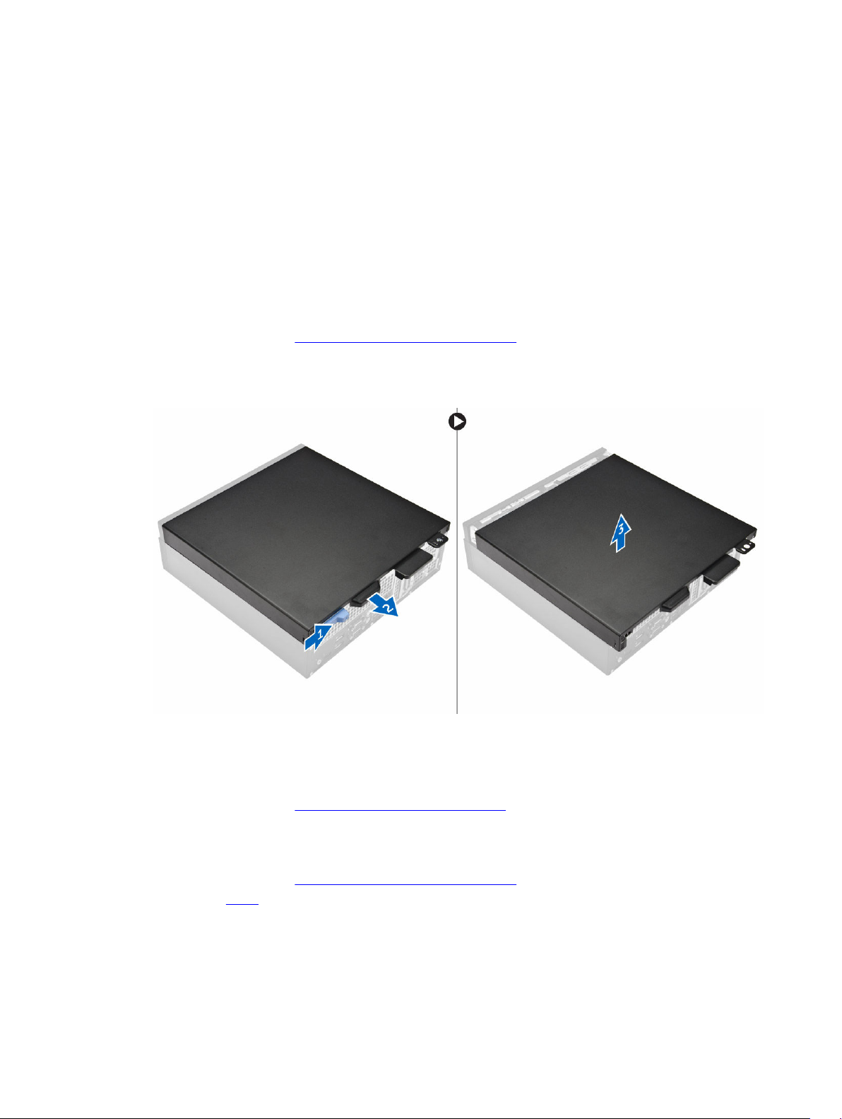
Removing the cover
1. Follow the procedure in Before Working Inside Your Computer.
2. To remove the cover:
a. Slide the cover toward the back of the computer [2].
b. Lift the cover from the computer [3].
2
Installing the cover
1. Place the cover on the computer and slide the cover until it clicks into place.
2. Follow the procedure in After Working Inside Your Computer
Removing the front bezel
1. Follow the procedure in Before Working Inside Your Computer.
2. Remove the cover.
3. To remove the front bezel:
a. Lift the tabs to release the front bezel from the computer [1].
b. Remove the front bezel from the computer [2].
8
Page 9
Installing the front bezel
1. Insert the tabs on the bezel into the slots on the computer.
2. Press the bezel until the tabs clicks into place.
3. Install the cover.
4. Follow the procedure in After Working Inside Your Computer
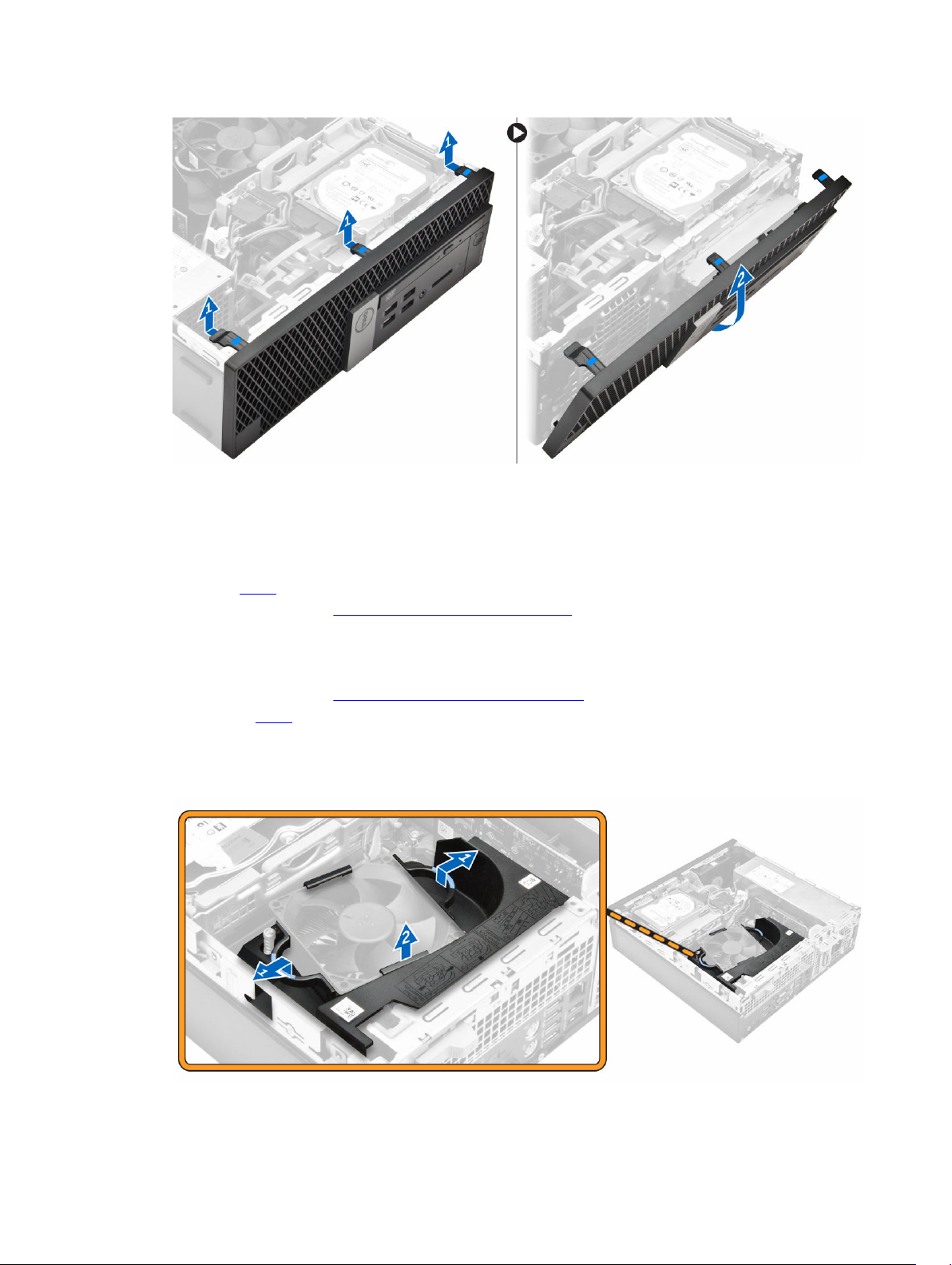
Removing the fan duct
1. Follow the procedure in Before Working Inside Your Computer.
2. Remove the cover.
3. To remove the fan duct:
a. Holding the touch points, pull the fan duct bracket to release the fan duct [1].
b. Lift the fan duct away from the computer [2].
9
Page 10
Installing the fan duct
1. Align the slots on the fan duct, with the screws on the heat sink.
2. Insert the fan duct until it clicks into place.
3. Install the cover.
4. Follow the procedure in After Working Inside Your Computer.
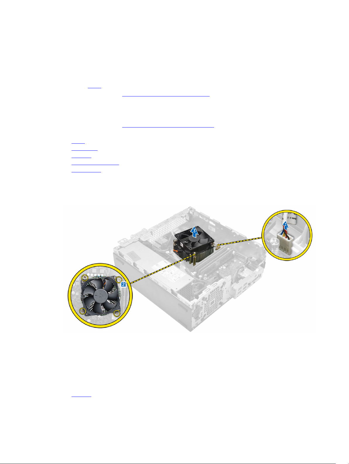
Removing the heat sink assembly
1. Follow the procedure in Before Working Inside Your Computer.
2. Remove the:
a. cover
b. front bezel
c. fan duct
d. hard drive assembly
e. optical drive
3. To remove the heat sink assembly:
a. Disconnect the heat sink cable from the system board. [1]
b. Loosen the captive screws that secure the heat sink assembly and lift it away from the computer
[2] [3].
Installing the heat sink assembly
1. Place the heat sink assembly onto the processor.
2. Tighten the captive screws to secure the heat sink assembly to the system board.
3. Connect the heat sink cable to the system board.
4. Install the:
a. fan duct
10
Page 11
b. optical drive
c. hard drive assembly
d. front bezel
e. cover
5. Follow the procedure in After Working Inside Your Computer.
Removing the processor
1. Follow the procedure in Before Working Inside Your Computer.
2. Remove the:
a. cover
b. front bezel
c. hard drive assembly
d. optical drive
e. fan duct
f. heat sink
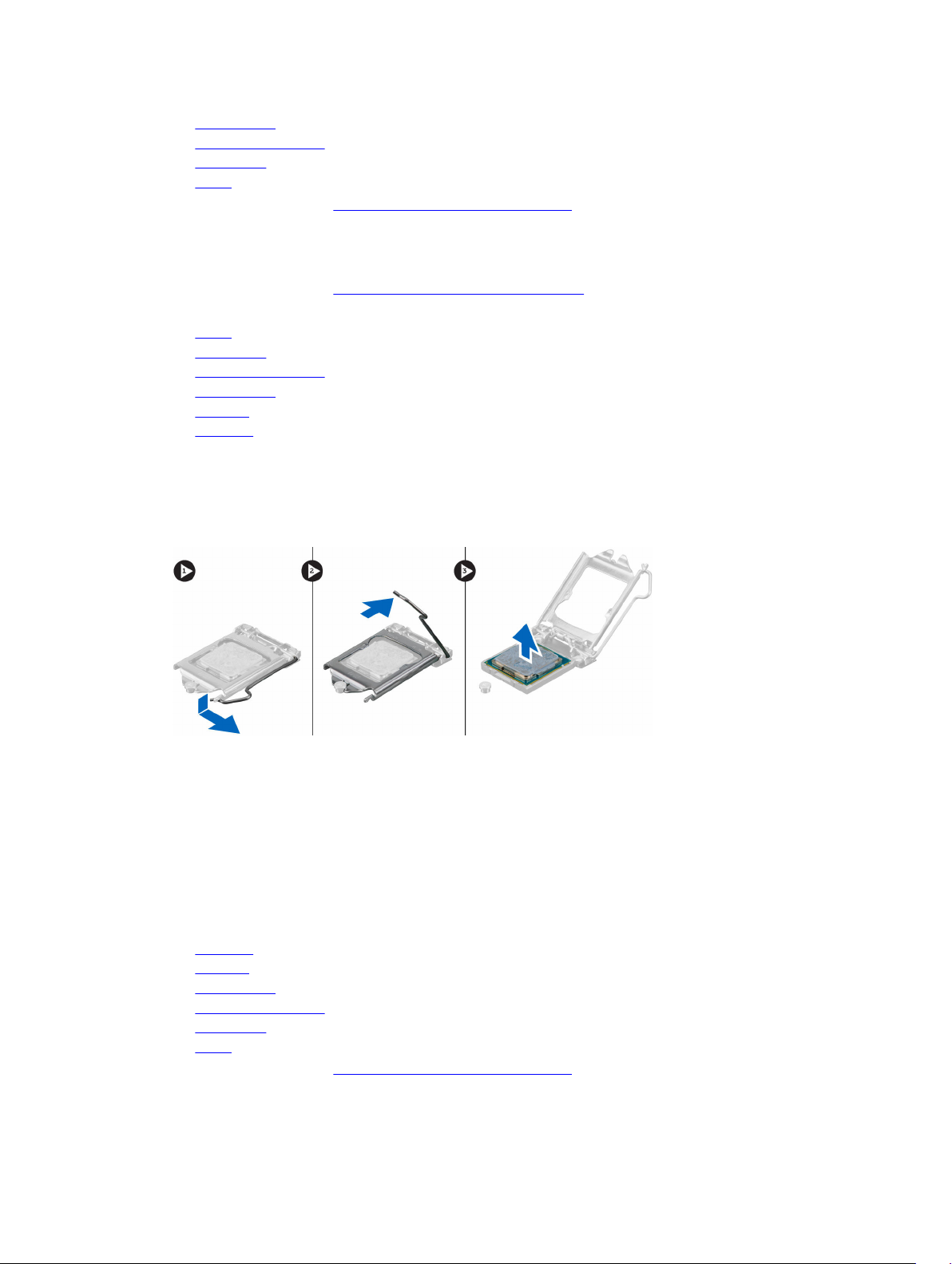
3. To remove the processor:
a. Release the socket lever by pushing the lever down and out from under the tab on the processor
shield [1].
b. Lift the lever upward and lift the processor shield [2].
c. Lift the processor out of the socket [3].
Installing the processor
1. Align the processor with the socket keys.
2. Align the pin-1 indicator of the processor with the triangle on the socket.
3. Place the processor on the socket such that the slots on the processor align with the socket keys.
4. Close the processor shield by sliding it under the retention screw.
5. Lower the socket lever and push it under the tab to lock it.
6. Install the:
a. heat sink
b. fan duct
c. optical drive
d. hard drive assembly
e. front bezel
f. cover
7. Follow the procedure in After Working Inside Your Computer.
11
Page 12
Removing the memory module
1. Follow the procedure in Before Working Inside Your Computer.
2. Remove the:
a. cover
b. fan duct
c. hard drive assembly
d. optical drive
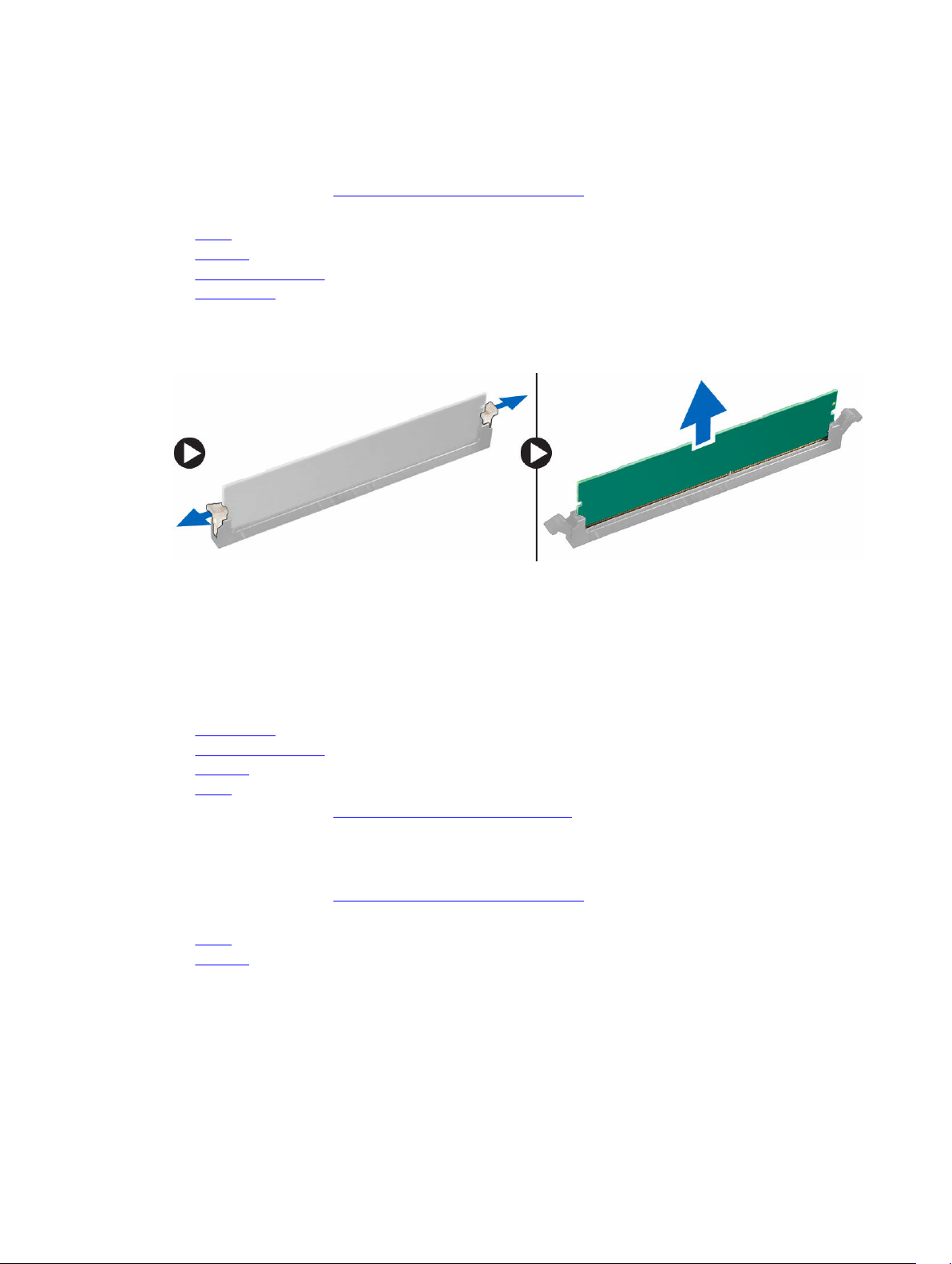
3. To remove the memory module:
a. Press the memory module retention tabs on both sides of the memory module.
b. Lift the memory module from the memory module connector on the system board.
Installing the memory module
1. Align the notch on the memory module with the tab on the memory module connector.
2. Insert the memory module into the memory module socket.
3. Press the memory module until the memory module retention tabs click into place.
4. Install the:
a. optical drive
b. hard drive assembly
c. fan duct
d. cover
5. Follow the procedure in After Working Inside Your Computer.
Removing the hard drive assembly
1. Follow the procedure in Before Working Inside Your Computer.
2. Remove the:
a. cover
b. fan duct
3. To release the hard drive assembly:
a. Push the retention tabs and remove the power connector [1,2].
b. Disconnect the data and power cables from the hard drives [3, 4].
12
Page 13
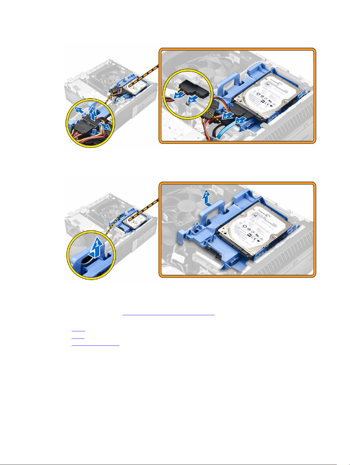
4. To remove the hard drive assembly:
a. Pull the hard drive release handle forward to release the hard drive bracket from the computer [1].
b. Lift the hard drive assembly away from the computer [2].
Removing the hard drive from the hard drive bracket
1. Follow the procedure in Before Working Inside Your Computer.
2. Remove the:
a. cover
b. bezel
c. hard drive assembly
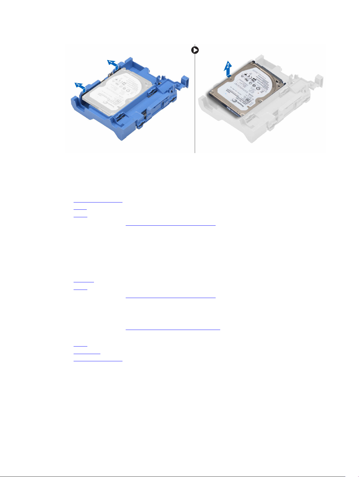
3. To remove the hard drive bracket:
a. Pull the hard drive bracket to release the hard drive [1].
b. Lift the hard drive out of the hard drive bracket [2].
13
Page 14
Installing the hard drive into the hard drive bracket
1. Insert the hard drive into the hard drive bracket until it clicks into place.
2. Install the:
a. hard drive assembly
b. bezel
c. cover
3. Follow the procedure in After Working Inside Your Computer.
Installing the hard drive assembly
1. Insert the hard drive assembly into the slot on the computer.
2. Connect the power cable to the slot on the hard drive bracket.
3. Install the:
a. fan duct
b. cover
4. Follow the procedure in After Working Inside Your Computer.
Removing the optical drive
1. Follow the procedure in Before Working Inside Your Computer.
2. Remove the:
a. cover
b. front bezel
c. hard drive assembly
3. To release the optical drive:
a. Remove the hard drive connector cables from the optical drive latch [1].
b. Slide the blue latch to the unlock position [2].
14
Page 15
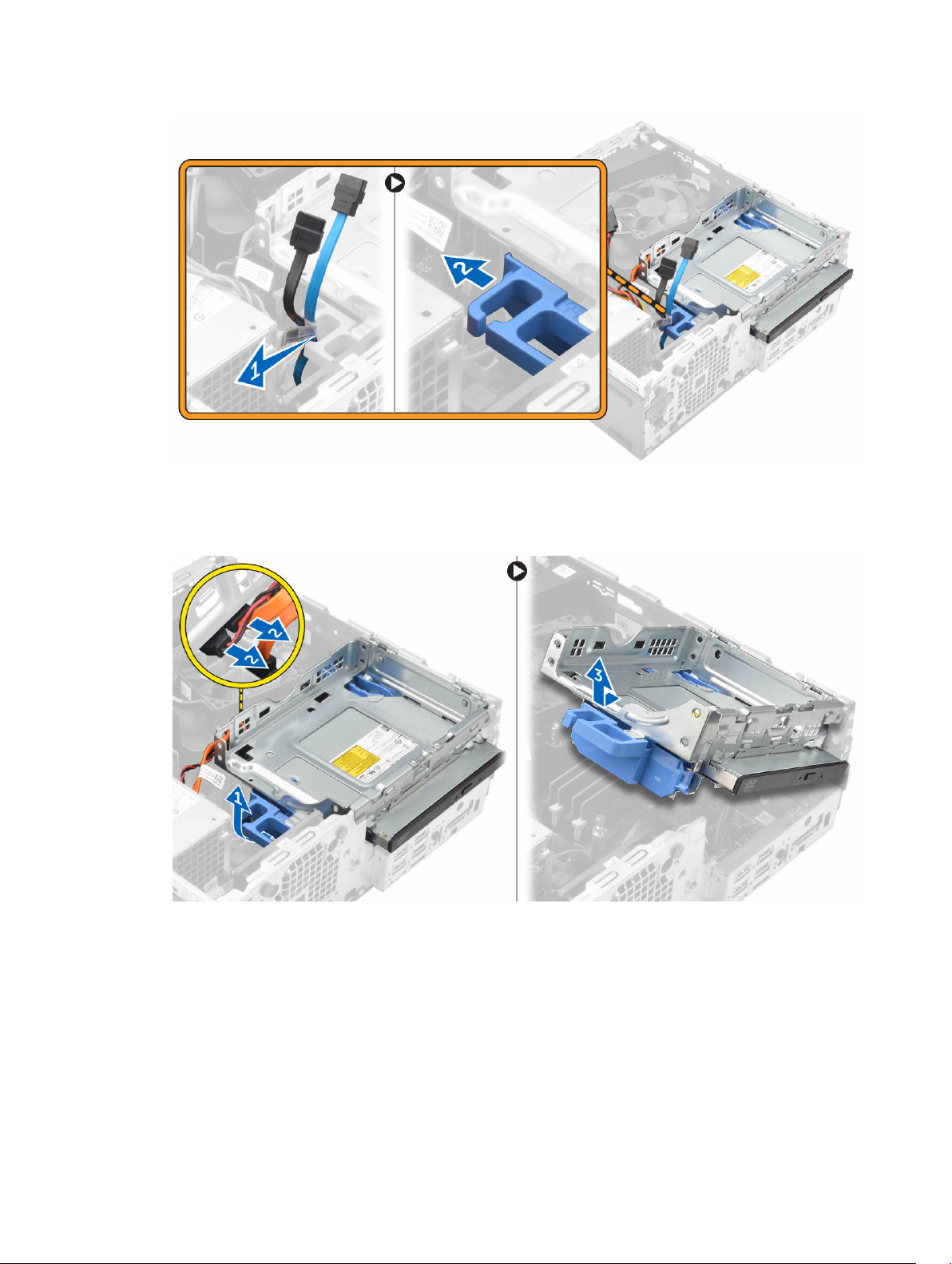
4. To remove the optical drive:
a. Holding the blue latch [1], lift the optical drive cage and disconnect the cables from the optical
drive. [2]
b. Lift the optical drive cage away from the computer [3].
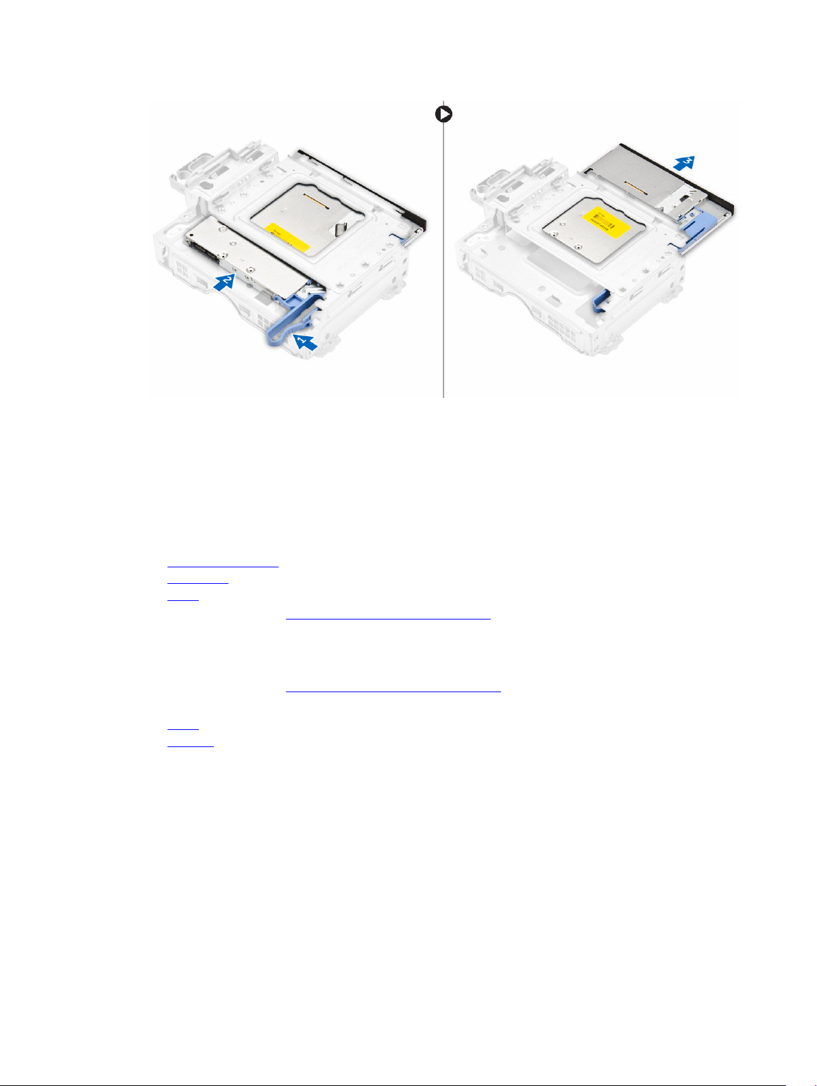
5. To remove the optical drive from the optical drive cage:
a. Press the optical drive release latch [1] and slide the optical drive forward. [2]
b. Remove the optical drive from the optical drive cage [3].
15
Page 16
Installing the optical drive
1. Slide the optical drive into the optical drive cage.
2. Align the tabs on the optical cage with the slots on the computer.
3. Lower the optical drive cage into the computer and lock the latch.
4. Connect the data and power cables to the optical drive.
5. Install the:
a. hard drive assembly
b. front bezel
c. cover
6. Follow the procedure in After Working Inside Your Computer.
Removing the expansion card
1. Follow the procedure in Before Working Inside Your Computer.
2. Remove the:
a. cover
b. fan duct
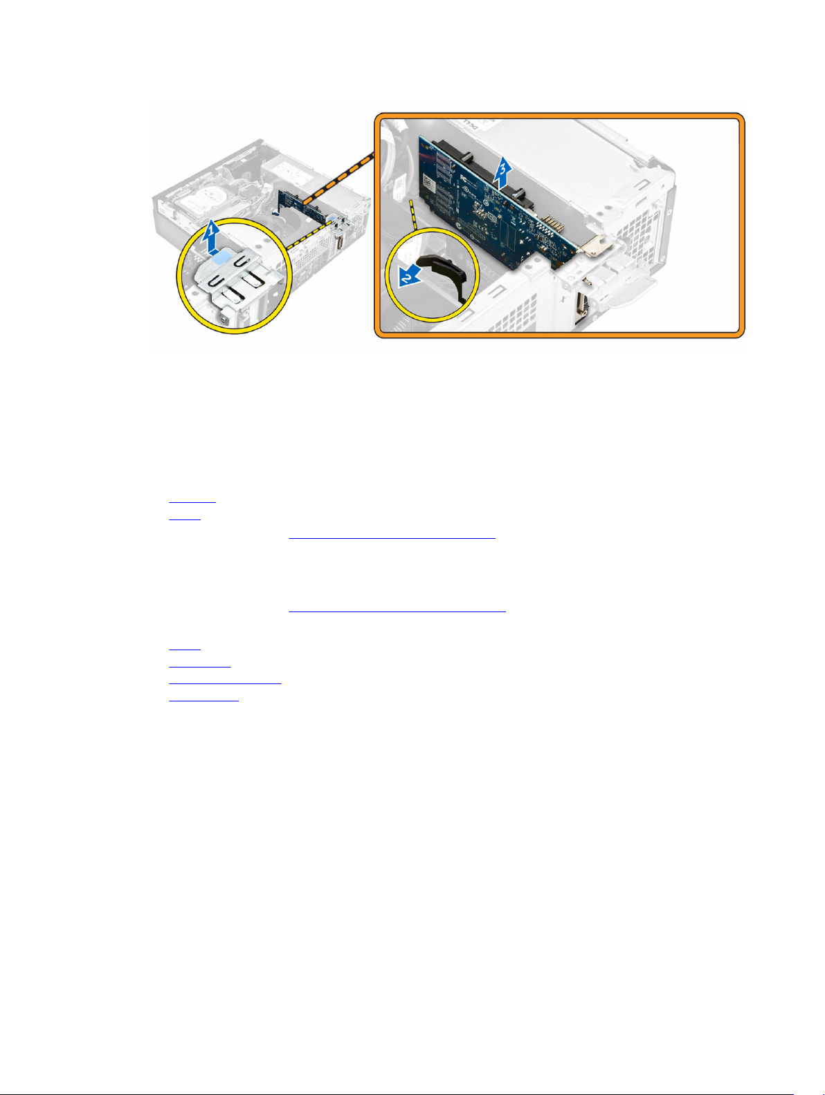
3. To remove the expansion card:
a. Pull the metal tab to open the expansion card latch [1].
b. Pull the tab forward [2] and pull the expansion card from the connector on the computer [3].
16
Page 17
Installing the expansion card
1. Insert the expansion card into the connector on the system board.
2. Press the expansion card until it clicks into place.
3. Close the expansion card latch and press it until it clicks into place.
4. Install the:
a. fan duct
b. cover
5. Follow the procedure in After Working Inside Your Computer.
Removing the system fan
1. Follow the procedure in Before Working Inside Your Computer.
2. Remove the:
a. cover
b. front bezel
c. hard drive assembly
d. optical drive
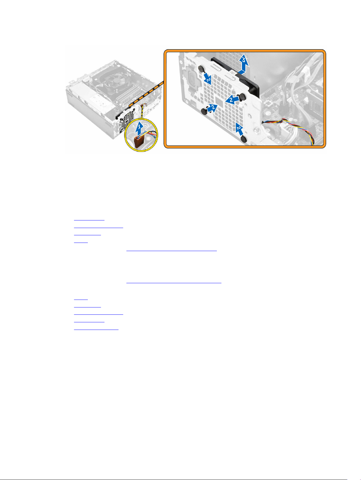
3. To remove the system fan:
a. Disconnect the system fan cable from the system board [1].
b. Slide the fan grommets toward the slot on the back wall [2].
c. Lift the fan away from the computer. [3]
17
Page 18
Installing the system fan
1. Place the system fan in the computer.
2. Pass the grommets through the chassis and slide outward along the groove to secure it in place.
3. Connect the system fan cable to the system board.
4. Install the:
a. optical drive
b. hard drive assembly
c. front bezel
d. cover
5. Follow the procedure in After Working Inside Your Computer.
Removing the power switch
1. Follow the procedure in Before Working Inside Your Computer.
2. Remove the:
a. cover
b. front bezel
c. hard drive assembly
d. optical drive
e. power supply unit
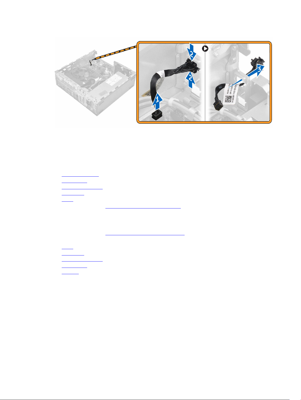
3. To remove the power switch:
a. Disconnect the power switch cable from the system board [1].
b. Press the power switch retention tabs and remove it from the chassis [2] [3].
18
Page 19
Installing the power switch
1. Slide the power switch module into the slot on the chassis until it clicks into place.
2. Connect the power switch cable to the connector on the system board.
3. Install the:
a. power supply unit
b. optical drive
c. hard drive assembly
d. front bezel
e. cover
4. Follow the procedure in After Working Inside Your Computer.
Removing the power supply unit (PSU)
1. Follow the procedure in Before Working Inside Your Computer.
2. Remove the:
a. cover
b. front bezel
c. hard drive assembly
d. optical drive
e. fan duct
3. To release the PSU:
a. Disconnect the power cable from the system board [1] [2].
b. Unroute the power cables from the retention clips on the chassis [3] [4].
19
Page 20

4. To remove the PSU:
a. Disconnect the power cable from the system board [1] [2].
b. Lift the cables away from the computer [3].
c. Remove the screws that secure the PSU to the computer [4].
5. Press the blue release tab [1], slide the PSU and lift it away from the computer [2].
20
Page 21

Installing the power supply unit (PSU)
1. Insert the PSU in the chassis and slide it toward the back of the computer to secure it.
2. Tighten the screws to secure the PSU to the back of the computer.
3. Route the PSU cables through the retention clips.
4. Connect the power cables to the system board.
5. Install the:
a. fan duct
b. optical drive
c. hard drive assembly
d. front bezel
e. cover
6. Follow the procedure in After Working Inside Your Computer.
Removing the VGA daughter board
1. Follow the procedure in Before Working Inside Your Computer.
2. Remove the:
a. cover
b. fan duct
3. To remove the VGA daughter board:
a. Remove the screws that secure the VGA connector to the computer [1].
b. Slide the VGA connector to release it from the computer [2].
c. Remove the screw that secures the VGA daughter board to the computer [3].
d. Lift the VGA daughter board using the handle to remove it from the computer [4].
21
Page 22

Installing the VGA daughter board
1. Align the VGA daughter board with the screw holder on the system board.
2. Tighten the screw to secure the VGA daughter board to the system board.
3. Insert the VGA connector into the slot at the back of the computer.
4. Tighten the screws to secure the VGA connector to the computer.
5. Install the:
a. fan duct
b. cover
6. Follow the procedure in After Working Inside Your Computer.
Removing the intrusion switch
1. Follow the procedure in Before Working Inside Your Computer.
2. Remove the:
a. cover
b. fan duct
3. To remove the intrusion switch:
a. Disconnect the intrusion switch cable from the connector on the system board [1][2].
b. Slide the intrusion switch and lift it away from the computer [3].
22
Page 23

Installing the intrusion switch
1. Insert the intrusion switch into the slot on the chassis.
2. Connect the intrusion switch cable to the system board.
3. Install the:
a. fan duct
b. cover
4. Follow the procedure in After Working Inside Your Computer.
Removing the SD card reader
1. Follow the procedure in Before Working Inside Your Computer.
2. Remove the:
a. cover
b. front bezel
c. hard drive assembly
d. optical drive
e. power supply unit
3. To remove the SD card reader:
a. Remove the power supply unit cables from the retention clips on the SD card reader enclosure
[1].
b. Remove the screws that secure the SD card reader and lift it away from the computer [2] [3].
23
Page 24

Installing the SD card reader
1. Place the SD card reader on the chassis.
2. Tighten the screws that secure the SD card reader to the computer.
3. Route the power supply unit cables into the retention clips.
4. Install the:
a. power supply unit
b. optical drive
c. hard drive assembly
d. front bezel
e. cover
5. Follow the procedure in After Working Inside Your Computer.
Installing the optional SSD card
1. Remove the:
a. cover
b. front bezel
2. Peel the adhesive tape (blue) from the rubber.
24
Page 25

3. Place the rubber on the computer [1] and peel the adhesive tape (pink) from the rubber [2].
4. To install the SSD card:
a. Connect the SSD card to the connector on the system board [1].
b. Tighten the screw to secure the SSD card to the system board [2].
25
Page 26

Removing the optional SSD card
1. Follow the procedure in Before Working Inside Your Computer.
2. Remove the:
a. cover
b. front bezel
3. To remove the SSD card:
a. Remove the screw that secures the SSD card to the computer.
b. Disconnect the SSD card from the connector.
c. Lift the SSD card.
d. Peel away the rubber adhesive from the system board.
Removing the system board
1. Follow the procedure in Before Working Inside Your Computer.
2. Remove the:
a. cover
b. fan duct
c. front bezel
d. memory module
e. hard drive assembly
f. optical drive
g. expansion card
h. optional SSD card
i. SD card reader
j. VGA daughter board
k. heat sink
l. processor
3. To remove the I/O panel:
a. Remove the screw that secures the I/O panel to the chassis [1].
b. Remove the I/O panel from the computer [2].
26
Page 27

4. Disconnect all the cables connected to the system board.
5. To remove the system board:
a. Remove the screws that secure the system board to the computer [1].
b. Slide the system board toward the front of the computer and lift it from the computer [2].
27
Page 28

Installing the system board
1. Hold the system board by its edges and angle it toward the back of the computer.
2. Lower the system board into the computer until the connectors at the back of the system board
align with the slots on the back wall of the computer, and the screw holes on the system board align
with the standoffs on the computer.
3. Tighten the screws that secure the system board to the computer.
4. Connect the cables to the system board.
5. Install the:
a. VGA daughter board
b. SD card reader
c. optional SSD card
d. expansion card
e. processor
f. heat sink
g. optical drive
h. hard drive assembly
i. memory module
j. front bezel
k. fan duct
l. cover
6. Place the I/O panel on the chassis.
7. Tighten the screws to secure the I/O panel to the chassis.
8. Follow the procedure in After Working Inside Your Computer.
28
Page 29

System board layout
1. PCIex16 connector 2. PCIex4 connector
3. RJ-45/USB 2.0 connector 4. USB 3.0 connector
5. PS2 keyboard/MS connector 6. Serial port connector
7. DisplayPort connector 8. HDMI connector
9. Line-out connector 10. CPU power connector
11. Intrusion switch connector 12. VGA daughter board connector
13. Processor 14. CPU fan connector
15. Memory module connectors 16. M.2 socket3 connector
17. Power switch connector 18. Media card reader connector
19. System fan connector 20. Hard drive activity LED
21. Universal audio jack 22. USB 2.0 connector
23. USB 3.0 connector 24. ATX power connector
25. SATA2 connector 26. SATA0 connector
27. Internal speaker connector 28. Hard drive and optical drive power cable
connector
29
Page 30

29. Internal USB connector 30. SATA1 connector
31. Coin cell battery
30
Page 31

Troubleshooting your computer
You can troubleshoot your computer using indicators like diagnostic lights, beep codes, and error
messages during the operation of the computer.
Diagnostic power LED codes
Table 1. Diagnostic power LED codes
Power LED light status Possible cause Troubleshooting steps
Off The computer is either
turned off or is not
receiving power or in
Hibernation mode.
• Re-seat the power
cable in the power
connector on the
back of the
computer and the
electrical outlet.
• If the computer is
plugged into a power
strip, ensure that the
power strip is
plugged into an
electrical outlet and
is turned on. Also,
bypass power
protection devices,
power strips, and
power extension
cables to verify that
the computer turns
on properly.
• Ensure the electrical
outlet is working by
testing it with
another device, such
as a lamp.
3
Steady/blinking amber Computer fails to
complete POST or
processor failure.
Slow Blinking white light Computer is in sleep
mode.
• Remove and reinstall
any cards.
• Remove and reinstall
the graphics card, if
applicable.
• Ensure the power
cable is connected
to the system board
and processor.
• Press the power
button to bring the
computer out of the
sleep mode.
• Ensure all power
cables are securely
31
Page 32

Power LED light status Possible cause Troubleshooting steps
connected to the
system board.
• Ensure the main
power cable and
front panel cable are
connected to the
system board.
Steady white The computer is fully
functional and in the On
state.
Diagnostic error messages
Table 2. Diagnostic error messages
Error messages Description
AUXILIARY DEVICE FAILURE
BAD COMMAND OR FILE NAME
CACHE DISABLED DUE TO FAILURE
The touchpad or external mouse may be faulty. For
an external mouse, check the cable connection.
Enable the Pointing Device option in the System
Setup program.
Ensure that you have spelled the command
correctly, put spaces in the proper place, and used
the correct path name.
The primary cache internal to the microprocessor
has failed. Contact Dell.
If the computer is not
responding, do the
following:
• Ensure the display is
connected and
turned on.
• If the display is
connected and
turned on, listen for a
beep code.
CD DRIVE CONTROLLER FAILURE
DATA ERROR
DECREASING AVAILABLE MEMORY
DISK C: FAILED INITIALIZATION
DRIVE NOT READY
ERROR READING PCMCIA CARD
32
The optical drive does not respond to commands
from the computer.
The hard drive cannot read the data.
One or more memory modules may be faulty or
improperly seated. Reinstall the memory modules
or, if necessary, replace them.
The hard drive failed initialization. Run the hard
drive tests in Dell Diagnostics.
The operation requires a hard drive in the bay
before it can continue. Install a hard drive in the
hard drive bay.
The computer cannot identify the ExpressCard.
Reinsert the card or try another card.
Page 33

Error messages Description
EXTENDED MEMORY SIZE HAS CHANGED
The amount of memory recorded in non-volatile
memory (NVRAM) does not match the memory
module installed in the computer. Restart the
computer. If the error appears again, Contact Dell
THE FILE BEING COPIED IS TOO LARGE FOR
THE DESTINATION DRIVE
A FILENAME CANNOT CONTAIN ANY OF THE
FOLLOWING CHARACTERS: \ / : * ? " < > |
-
GATE A20 FAILURE
GENERAL FAILURE
HARD-DISK DRIVE CONFIGURATION ERROR
HARD-DISK DRIVE CONTROLLER FAILURE 0
The file that you are trying to copy is too large to fit
on the disk, or the disk is full. Try copying the file to
a different disk or use a larger capacity disk.
Do not use these characters in filenames.
A memory module may be loose. Reinstall the
memory module or, if necessary, replace it.
The operating system is unable to carry out the
command. The message is usually followed by
specific information. For example, Printer out
of paper. Take the appropriate action.
The computer cannot identify the drive type. Shut
down the computer, remove the hard drive, and
boot the computer from an optical drive. Then,
shut down the computer, reinstall the hard drive,
and restart the computer. Run the Hard Disk Drive
tests in Dell Diagnostics.
The hard drive does not respond to commands
from the computer. Shut down the computer,
remove the hard drive, and boot the computer
from an optical drive. Then, shut down the
computer, reinstall the hard drive, and restart the
computer. If the problem persists, try another
drive. Run the Hard Disk Drive tests in Dell
Diagnostics.
HARD-DISK DRIVE FAILURE
HARD-DISK DRIVE READ FAILURE
The hard drive does not respond to commands
from the computer. Shut down the computer,
remove the hard drive, and boot the computer
from an optical drive. Then, shut down the
computer, reinstall the hard drive, and restart the
computer. If the problem persists, try another
drive. Run the Hard Disk Drive tests in Dell
Diagnostics.
The hard drive may be defective. Shut down the
computer, remove the hard drive, and boot the
computer from an optical. Then, shut down the
computer, reinstall the hard drive, and restart the
computer. If the problem persists, try another
drive. Run the Hard Disk Drive tests in Dell
Diagnostics.
33
Page 34

Error messages Description
INSERT BOOTABLE MEDIA
The operating system is trying to boot to nonbootable media, such as an optical drive. Insert
bootable media.
INVALID CONFIGURATION INFORMATIONPLEASE RUN SYSTEM SETUP PROGRAM
KEYBOARD CLOCK LINE FAILURE
KEYBOARD CONTROLLER FAILURE
KEYBOARD DATA LINE FAILURE
KEYBOARD STUCK KEY FAILURE
LICENSED CONTENT IS NOT ACCESSIBLE IN
MEDIADIRECT
The system configuration information does not
match the hardware configuration. The message is
most likely to occur after a memory module is
installed. Correct the appropriate options in the
system setup program.
For external keyboards, check the cable
connection. Run the Keyboard Controller test in
Dell Diagnostics.
For external keyboards, check the cable
connection. Restart the computer, and avoid
touching the keyboard or the mouse during the
boot routine. Run the Keyboard Controller test in
Dell Diagnostics.
For external keyboards, check the cable
connection. Run the Keyboard Controller test in
Dell Diagnostics.
For external keyboards or keypads, check the cable
connection. Restart the computer, and avoid
touching the keyboard or keys during the boot
routine. Run the Stuck Key test in Dell Diagnostics.
Dell MediaDirect cannot verify the Digital Rights
Management (DRM) restrictions on the file, so the
file cannot be played.
MEMORY ADDRESS LINE FAILURE AT ADDRESS,
READ VALUE EXPECTING VALUE
MEMORY ALLOCATION ERROR
MEMORY DOUBLE WORD LOGIC FAILURE AT
ADDRESS, READ VALUE EXPECTING VALUE
MEMORY ODD/EVEN LOGIC FAILURE AT
ADDRESS, READ VALUE EXPECTING VALUE
34
A memory module may be faulty or improperly
seated. Reinstall the memory module or, if
necessary, replace it.
The software you are attempting to run is
conflicting with the operating system, another
program, or a utility. Shut down the computer, wait
for 30 seconds, and then restart it. Run the
program again. If the error message still appears,
see the software documentation.
A memory module may be faulty or improperly
seated. Reinstall the memory module or, if
necessary, replace it.
A memory module may be faulty or improperly
seated. Reinstall the memory module or, if
necessary, replace it.
Page 35

Error messages Description
MEMORY WRITE/READ FAILURE AT ADDRESS,
READ VALUE EXPECTING VALUE
A memory module may be faulty or improperly
seated. Reinstall the memory module or, if
necessary, replace it.
NO BOOT DEVICE AVAILABLE
NO BOOT SECTOR ON HARD DRIVE
NO TIMER TICK INTERRUPT
NOT ENOUGH MEMORY OR RESOURCES. EXIT
SOME PROGRAMS AND TRY AGAIN
OPERATING SYSTEM NOT FOUND
OPTIONAL ROM BAD CHECKSUM
SECTOR NOT FOUND
The computer cannot find the hard drive. If the
hard drive is your boot device, ensure that the drive
is installed, properly seated, and partitioned as a
boot device.
The operating system may be corrupted, Contact
Dell.
A chip on the system board may be
malfunctioning. Run the System Set tests in Dell
Diagnostics.
You have too many programs open. Close all
windows and open the program that you want to
use.
Reinstall the operating system. If the problem
persists, Contact Dell.
The optional ROM has failed. Contact Dell.
The operating system cannot locate a sector on
the hard drive. You may have a defective sector or
corrupted File Allocation Table (FAT) on the hard
drive. Run the Windows error-checking utility to
check the file structure on the hard drive. See
Windows Help and Support for instructions (click
Start → Help and Support). If a large number of
sectors are defective, back up the data (if possible),
and then format the hard drive.
SEEK ERROR
SHUTDOWN FAILURE
TIME-OF-DAY CLOCK LOST POWER
TIME-OF-DAY CLOCK STOPPED
The operating system cannot find a specific track
on the hard drive.
A chip on the system board may be
malfunctioning. Run the System Set tests in Dell
Diagnostics. If the message reappears, Contact
Dell.
System configuration settings are corrupted.
Connect your computer to an electrical outlet to
charge the battery. If the problem persists, try to
restore the data by entering the System Setup
program, then immediately exit the program. If the
message reappears, Contact Dell.
The reserve battery that supports the system
configuration settings may require recharging.
Connect your computer to an electrical outlet to
35
Page 36

Error messages Description
charge the battery. If the problem persists, Contact
Dell.
TIME-OF-DAY NOT SET-PLEASE RUN THE
SYSTEM SETUP PROGRAM
TIMER CHIP COUNTER 2 FAILED
UNEXPECTED INTERRUPT IN PROTECTED MODE
X:\ IS NOT ACCESSIBLE. THE DEVICE IS
NOT READY
The time or date stored in the system setup
program does not match the system clock. Correct
the settings for the Date and Time options.
A chip on the system board may be
malfunctioning. Run the System Set tests in Dell
Diagnostics.
The keyboard controller may be malfunctioning, or
a memory module may be loose. Run the System
Memory tests and the Keyboard Controller test in
Dell Diagnostics or Contact Dell.
Insert a disk into the drive and try again.
System error messages
Table 3. System error messages
System message Description
Alert! Previous attempts at booting
this system have failed at checkpoint
[nnnn]. For help in resolving this
problem, please note this checkpoint
and contact Dell Technical Support
The computer failed to complete the boot routine
three consecutive times for the same error.
CMOS checksum error
CPU fan failure
System fan failure
Hard-disk drive failure
Keyboard failure
No boot device available
No timer tick interrupt
36
RTC is reset, BIOS Setup default has been loaded.
CPU fan has failed.
System fan has failed.
Possible hard disk drive failure during POST.
Keyboard failure or loose cable. If reseating the
cable does not solve the problem, replace the
keyboard.
No bootable partition on hard disk drive, the hard
disk drive cable is loose, or no bootable device
exists.
• If the hard drive is your boot device, ensure that
the cables are connected and that the drive is
installed properly and partitioned as a boot
device.
• Enter system setup and ensure that the boot
sequence information is correct.
A chip on the system board might be
malfunctioning or motherboard failure.
Page 37

System message Description
NOTICE - Hard Drive SELF MONITORING
SYSTEM has reported that a parameter
has exceeded its normal operating
range. Dell recommends that you back up
your data regularly. A parameter out of
range may or may not indicate a
potential hard drive problem
S.M.A.R.T error, possible hard disk drive failure.
37
Page 38

4
System Setup
System Setup enables you to manage your computer hardware and specify BIOS level options. From the
System Setup, you can:
• Change the NVRAM settings after you add or remove hardware
• View the system hardware configuration
• Enable or disable integrated devices
• Set performance and power management thresholds
• Manage your computer security
Boot Sequence
Boot Sequence allows you to bypass the System Setup‐defined boot device order and boot directly to a
specific device (for example: optical drive or hard drive). During the Power-on Self Test (POST), when the
Dell logo appears, you can:
• Access System Setup by pressing F2 key
• Bring up the one-time boot menu by pressing F12 key
The one-time boot menu displays the devices that you can boot from including the diagnostic option.
The boot menu options are:
• Removable Drive (if available)
• STXXXX Drive
NOTE: XXX denotes the SATA drive number.
• Optical Drive
• Diagnostics
NOTE: Choosing Diagnostics, will display the ePSA diagnostics screen.
The boot sequence screen also displays the option to access the System Setup screen.
Navigation keys
The following table displays the system setup navigation keys.
NOTE: For most of the System Setup options, changes that you make are recorded but do not take
effect until you restart the system.
38
Page 39

Table 4. Navigation keys
Keys Navigation
Up arrow Moves to the previous field.
Down arrow Moves to the next field.
Enter Allows you to select a value in the selected field (if applicable) or follow the link in
the field.
Spacebar Expands or collapses a drop‐down list, if applicable.
Tab Moves to the next focus area.
NOTE: For the standard graphics browser only.
Esc Moves to the previous page till you view the main screen. Pressing Esc in the main
screen displays a message that prompts you to save any unsaved changes and
restarts the system.
F1 Displays the System Setup help file.
System Setup overview
System Setup allows you to:
• Change the system configuration information after you add, change, or remove any hardware in your
computer.
• Set or change a user-selectable option such as the user password.
• Read the current amount of memory or set the type of hard drive installed.
Before you use System Setup, it is recommended that you write down the System Setup screen
information for future reference.
CAUTION: Unless you are an expert computer user, do not change the settings for this program.
Certain changes can cause your computer to work incorrectly.
Accessing System Setup
1. Turn on (or restart) your computer.
2. After the white Dell logo appears, press F2 immediately.
The System Setup page is displayed.
NOTE: If you wait too long and the operating system logo appears, wait until you see the
desktop. Then, shut down or restart your computer and try again.
NOTE: After the Dell logo appears, you can also press F12 and then select BIOS setup.
System Setup options
NOTE: Depending on the computer and its installed devices, the items listed in this section may or
may not appear.
39
Page 40

Table 5. General
Option Description
System Information Displays the following information:
• System Information: Displays BIOS Version, Service Tag, Asset Tag,
Ownership Date, Manufacture Date, and the Express Service Code.
• Memory Information: Displays Memory Installed, Memory Available,
Memory Speed, Memory Channels Mode, Memory Technology, DIMM 1
Size,, DIMM 2 Size, DIMM 3 Size, and DIMM 4 Size.
• PCI Information: Displays SLOT1, SLOT2, SLOT3, SLOT4, and SLOT5_M.
2
• Processor Information: Displays Processor Type, Core Count, Processor
ID, Current Clock Speed, Minimum Clock Speed, Maximum Clock
Speed, Processor L2 Cache, Processor L3 Cache, HT Capable, and 64Bit Technology.
• Device Information: Displays SATA-0, LOM MAC Address, Video
Controller, Audio Controller, Wi-Fi Device, and Bluetooth Device.
Boot Sequence
Allows you to specify the order in which the computer attempts to find an
operating system from the devices specified in this list.
• Legacy
• UEFI
Advanced Boot Options Allows you to select the Enable Legacy Option ROMs option, when in UEFI
boot mode. By default, this option is enabled.
Date/Time Allows you to set the date and time settings. Changes to the system date
and time take effect immediately.
Table 6. System Configuration
Option Description
Integrated NIC Allows you to control the on-board LAN controller. The options are:
• Disabled
• Enabled (default)
• Enabled w/PXE
• Enabled w/Cloud Desktop
NOTE: Depending on the computer and its installed devices, the items
listed in this section may or may not appear.
WIDI Allows you to connect to display through WiFi. WIDI requires Intel WiFi card,
Intel graphics, and WIDI receiver in display (or WIDI compliant display). To
install the WIDI application, see the dell.com/support site to download the
WIDI application.
NOTE: When installing the WIDI application, connect the display to Intel
on-board graphic output.
Serial Port Allows you to determine how the built-in serial port to operate. The options
are:
• Disabled
• COM 1 – Default setting
• COM 2
• COM 3
40
Page 41

Option Description
• COM 4
SATA Operation Allows you to configure the operating mode of the integrated hard drive
controller.
• Disabled = The SATA controllers are hidden
• ATA = SATA is configured for ATA mode
• RAID ON = SATA is configured to support RAID mode
Drives Allows you to enable or disable the various drives on-board:
• SATA-0
• SATA-1
• SATA-2
• SATA-3
Smart Reporting This field controls whether hard drive errors for integrated drives are
reported during system startup. This option is disabled by default.
USB Configuration Allows you to enable or disable the integrated USB controller for:
• Enable Boot Support
• Enable Front USB Ports
• Enable Rear USB Ports
All the options are enabled by default.
Front USB Configuration Allows you to enable or disable the front USB ports. All the ports are enabled
by default.
Back USB Configuration Allows you to enable or disable the back USB ports. All the ports are enabled
by default.
USB PowerShare This option allows you to charge the external devices, such as mobile
phones, music player. This option is disabled by default.
Audio Allows you to enable or disable the integrated audio controller.
• Enable Microphone
• Enable Internal Speaker
Both the options are enabled by default.
Miscellaneous Devices Allows you to enable or disable the various on-board devices.
• Enable PCI Slot
• Enable Media Card (default option)
• Disable Media Card
.
Table 7. Video
Option Description
Primary Display Allows you to select the primary display when multiple controllers are
available in the system.
• Auto
41
Page 42

Option Description
• Intel HD Graphics
NOTE: If you do not select Auto, the on-board graphics device will be
present and enabled.
Table 8. Security
Option Description
Admin Password Allows you to set, change, and delete the admin password.
System Password Allows you to set, change, and delete the system password.
Internal HDD-0 Password Allows you to set, change, and delete the computer’s internal HDD.
Internal HDD-0 Password Allows you to set, change, and delete the computer’s internal HDD.
Strong Password This option lets you enable or disable strong passwords for the system.
Password Configuration Allows you to control the minimum and maximum number of characters
allowed for a administrative password and the system password.
Password Bypass This option lets you bypass the System (Boot) Password and the internal
HDD password prompts during a system restart.
• Disabled — Always prompt for the system and internal HDD password
when they are set. This option is disabled by default.
• Reboot Bypass — Bypass the password prompts on Restarts (warm
boots).
NOTE: The system will always prompt for the system and internal HDD
passwords when powered on from the off state (a cold boot). Also, the
system will always prompt for passwords on any module bay HDDs that
may be present.
Password Change This option lets you determine whether changes to the System and Hard
Disk passwords are permitted when an administrator password is set.
Allow Non-Admin Password Changes - This option is enabled by default.
TPM 1.2 Security Allows you to control whether the Trusted Platform Module (TPM) is visible
to the operating system.
• TPM On (default)
• Clear
• PPI Bypass for Enable Commands
• PPI Bypass for Disable Commands
• Disabled
• Enabled (default)
Computrace This field lets you Activate or Disable the BIOS module interface of the
optional Computrace Service from Absolute Software. Enables or disables
the optional Computrace service designed for asset management.
• Deactivate - This option is disabled by default.
• Disable
• Activate
42
Page 43

Option Description
Chassis Intrusion Allows you to control the chassis intrusion feature. You can set this option
to:
• Enable
• Disable
• On-Silent — Enabled by default if chassis intrusion is detected.
CPU XD Support Allows you to enable or disable the Execute Disable mode of the processor.
This option is enabled by default.
OROM Keyboard Access This option determines whether users are able to enter Option ROM
Configuration screens via hotkeys during boot. Specifically, these settings
are capable of preventing access to Intel RAID (CTRL+I) or Intel
Management Engine BIOS Extension (CTRL+P/F12)
• Enable — User may enter OROM configuration screens via the hotkey.
• One-Time Enable — User may enter OROM configuration screens via
the hotkeys on next boot only. After next boot, the setting will revert to
disabled.
• Disable — User may not enter OROM configuration screens via the
hotkey.
This option is set to Enable by default.
Admin Setup Lockout Allows you to enable or disable the option to enter Setup when an
Administrative password is set. This option is not set by default.
HDD Protection Support Allows you to enable or disable the HDD Protection feature. This option is
an advanced feature, which is intended to keep the HDD data secure and
unchangeable. By default, this option is disabled.
Table 9. Secure Boot
Option Description
Secure Boot Enable Allows you to enable or disable Secure Boot feature
• Disable
• Enable
Expert key Management Allows you to manipulate the security key databases only if the system is in
Custom Mode. The Enable Custom Mode option is disabled by default.
The options are:
• PK
• KEK
• db
• dbx
If you enable the Custom Mode, the relevant options for PK, KEK, db, and
dbx
appear. The options are:
• Save to File- Saves the key to a user-selected file
• Replace from File- Replaces the current key with a key from a user-
selected file
• Append from File- Adds a key to the current database from a user-
selected file
• Delete- Deletes the selected key
• Reset All Keys- Resets to default setting
43
Page 44

Option Description
• Delete All Keys- Deletes all the keys
NOTE: If you disable the Custom Mode, all the changes made will be
erased and the keys will restore to default settings.
Table 10. Intel Software Guard Extensions
Option Description
Intel SGX Enable Allows you to enable or disable the Intel Software Guard Extensions to
provide a secured environment for running code/storing sensitive
information in the context of the main operating system.
• Disabled (default)
• Enabled
Enclave Memory Size Allows you to set the Intel SGX Enclave Reserve Memory Size.
• 32 MB
• 64 MB
• 128 MB
Table 11. Performance
Option Description
Multi Core Support This field specifies whether the process will have one or all cores enabled.
This option is enabled by default.
Intel SpeedStep Allows you to enable or disable the Intel SpeedStep mode of the processor.
This option is disabled by default.
C States Control Allows you to enable or disable additional processor sleep states. This option
is disabled by default.
Limited CPUID Value Allows you to limit the maximum value of the processor standard CPUID
function. This options is disable by default.
Intel TurboBoost Allows you to enable or disable the Intel TurboBoost mode of the processor.
This option is enabled by default.
HyperThread control Allows you to enable or disable HyperThreading in the processor.
Table 12. Power Management
Option Description
AC Recovery Determines how the system responds when AC power is re-applied after a
power loss. You can set the AC Recovery to:
• Power Off
• Power On
• Last Power State
This option is Power Off by default.
Auto On Time Sets time to automatically turn on the computer. Time is kept in standard
12-hour format (hour:minutes:seconds). Change the startup time by typing
the values in the time and AM/PM fields.
44
Page 45

Option Description
NOTE: This feature does not work if you turn off your computer using
the switch on a power strip or surge protector or if Auto Power is set to
disabled.
Deep Sleep Control Allows you to define the controls when Deep Sleep is enabled.
• Disabled
• Enabled in S5 only
• Enabled in S4 and S5
This option is Disabled by default.
Fan Control Override Allows you to determine the speed of the system fan. When this option is
enabled, the system fan runs at the maximum speed. This option is disabled
by default.
USB Wake Support Allows you to enable the USB devices to wake the computer from standby
mode.
Wake on LAN/WWAN This option allows the computer to power up from the off state when
triggered by a special LAN signal. This feature only works when the
computer is connected to AC power supply.
• Disabled - Does not allows the system to power on by special LAN
signals when it receives a wake-up signal from the LAN or wireless LAN.
• LAN or WLAN - Allows the system to be powered on by special LAN or
wireless LAN signals.
• LAN Only - Allows the system to be powered on by special LAN signals.
• LAN with PXE Boot - A wakeup packet sent to the system in either the
S4 or S5 state, that will cause the system to wake-up and immediately
boot to PXE.
• WLAN Only - Allows the system to be powered on by special WLAN
signals.
This option is Disabled by default.
Block Sleep
Allows you to block entering to sleep (S3 state) in OS environment. This
option is disabled by default.
Intel Ready Mode Allows you to enable the capability of Intel Ready Mode Technology. This
option is disabled by default.
Table 13. POST Behavior
Option Description
Numlock LED Allows you to enable or disable the Numlock feature when your computer
starts. This option is enabled by default.
MEBx Hotkey Allows you to specify whether the MEBx Hotkey function should be enabled
when the system boots. This option is enabled by default.
Keyboard Errors Allows you to enable or disable the keyboard error reporting when the
computer starts. This option is enabled by default.
Fast Boot This option can speed up the boot process by bypassing some compatibility
steps:
• Minimal — The system boots quickly, unless the BIOS has been updated,
memory changed, or the previous POST did not complete.
• Thorough — The system does not skip any steps in the boot process.
45
Page 46

Option Description
• Auto — This allows the operating system to control this setting (this
works only when the operating system supports Simple Boot Flag).
This option is set to Thorough by default.
Table 14. Virtualization Support
Option Description
Virtualization This option specifies whether a Virtual Machine Monitor (VMM) can utilize
the additional hardware capabilities provided by Intel® Virtualization
Technology. Enable Intel Virtualization Technology - This option is
disabled by default.
VT for Direct I/O Enables or disables the Virtual Machine Monitor (VMM) from utilizing the
additional hardware capabilities provided by Intel® Virtualization technology
for direct I/O. Enable Intel Virtualization Technology for Direct I/O - This
option is disabled by default.
Trusted Execution This option specifies whether a Measured Virtual Machine Monitor (MVMM)
can utilize the additional hardware capabilities provided by the Intel Trusted
Execution Technology. This option is disabled by default.
Table 15. Maintenance
Option Description
Service Tag Displays the Service Tag of your computer.
Asset Tag Allows you to create a system asset tag if an asset tag is not already set. This
option is not set by default.
SERR Messages Controls the SERR message mechanism. This option is not set by default.
Some graphics cards require that the SERR message mechanism be
disabled.
Dell Development
Configuration
Allows you to turn on/off certain features to control the BIOS. This option is
disabled by default.
BIOS Downgrade Allows you to control flashing of the system firmware to the previous
versions. This option is enabled by default.
NOTE: If this option is not selected, the flashing of the system firmware
to the previous versions is blocked.
Data Wipe Allows you to securely erase the data from all the available internal storages,
such as HDD, SSD, mSATA, and eMMC. This option is disabled by default.
BIOS recovery Allows you to recover the corrupted BIOS conditions from the recovery files
on the primary hard drive or an external USB key.
Table 16. Cloud Desktop
Option Description
Server Lookup Method Allows you to specify how the cloud desktop software will lookup server
addresses.
• Static
46
Page 47

Option Description
• DNS (Default)
Server Name Allows you to specify the name of the server
Server IP Address Specifies the primary static IP address of the cloud desktop server. The
default IP address is 255.255.255.255
Server port Specifies the primary port of the cloud desktop. The default setting is 06910.
Client Address Method Specifies how the client will obtain the IP address.
• Static IP
• DHCP (Default)
Client IP address Specifies the static IP address of the client. The default IP address is
255.255.255.255
Client Subnet Mask Specifies the subnet mask address of the client. The default IP address is
255.255.255.255
Client Gateway Specifies the gateway address of the client. The default IP address is
255.255.255.255
DNS IP Address Specifies the DNS IP address of the client. The default IP address is
255.255.255.255
Domain Name Specifies the domain name of the client.
Advanced Allows you to turn on the Verbose mode for advanced debugging. This
option is disabled by default.
Table 17. System Logs
Option Description
BIOS Events Displays the system event log and allows you to:
• Clear Log
• Mark all Entries
Table 18. Advanced configurations
Option Description
ASPM Allows you to activate the state power management.
• Auto (Default)
• Disabled
• L1 Only
System Setup options
NOTE: Depending on the computer and its installed devices, the items listed in this section may or
may not appear.
47
Page 48

Table 19. General
Option Description
System Information Displays the following information:
• System Information: Displays BIOS Version, Service Tag, Asset Tag,
Ownership Date, Manufacture Date, and the Express Service Code.
• Memory Information: Displays Memory Installed, Memory Available,
Memory Speed, Memory Channels Mode, Memory Technology, DIMM 1
Size,, DIMM 2 Size, DIMM 3 Size, and DIMM 4 Size.
• PCI Information: Displays SLOT1, SLOT2, SLOT3, SLOT4, and SLOT5_M.
2
• Processor Information: Displays Processor Type, Core Count, Processor
ID, Current Clock Speed, Minimum Clock Speed, Maximum Clock
Speed, Processor L2 Cache, Processor L3 Cache, HT Capable, and 64Bit Technology.
• Device Information: Displays SATA-0, LOM MAC Address, Video
Controller, Audio Controller, Wi-Fi Device, and Bluetooth Device.
Boot Sequence
Allows you to specify the order in which the computer attempts to find an
operating system from the devices specified in this list.
• Legacy
• UEFI
Advanced Boot Options Allows you to select the Enable Legacy Option ROMs option, when in UEFI
boot mode. By default, this option is enabled.
Date/Time Allows you to set the date and time settings. Changes to the system date
and time take effect immediately.
Table 20. System configuration
Option Description
Integrated NIC Allows you to control the on-board LAN controller. The options are:
• Disabled
• Enabled (default)
• Enabled w/PXE
• Enabled w/Cloud Desktop
NOTE: Depending on the computer and its installed devices, the items
listed in this section may or may not appear.
WIDI Allows you to connect to display through WiFi. WIDI requires Intel WiFi card,
Intel graphics, and WIDI receiver in display (or WIDI compliant display). To
install the WIDI application, see the Dell.com/support site to download the
WIDI application.
NOTE: When installing the WIDI application, connect the display to Intel
onboard graphic output.
Serial Port Allows you to determine how the built-in serial port to operate. The options
are:
• Disabled
• COM 1 – Default setting
• COM 2
• COM 3
48
Page 49

Option Description
• COM 4
SATA Operation Allows you to configure the operating mode of the integrated hard drive
controller.
• Disabled = The SATA controllers are hidden
• ATA = SATA is configured for ATA mode
• RAID ON = SATA is configured to support RAID mode
Drives Allows you to enable or disable the various drives on-board:
• SATA-0
• SATA-1
• SATA-2
Smart Reporting This field controls whether hard drive errors for integrated drives are
reported during system startup. This option is disabled by default.
USB Configuration Allows you to enable or disable the integrated USB controller for:
• Enable Boot Support
• Enable Front USB Ports
• Enable Rear USB Ports
All the options are enabled by default.
Front USB Configuration Allows you to enable or disable the front USB ports. All the ports are enabled
by default.
Back USB Configuration Allows you to enable or disable the back USB ports. All the ports are enabled
by default.
USB PowerShare This option allows you to charge the external devices, such as mobile
phones, music player. This option is disabled by default.
Audio Allows you to enable or disable the integrated audio controller.
• Enable Microphone
• Enable Internal Speaker
Both the options are enabled by default.
Miscellaneous Devices Allows you to enable or disable the various on-board devices.
• Enable PCI Slot
• Enable Media Card (default option)
• Disable Media Card
.
Table 21. Video
Option Description
Primary Display Allows you to select the primary display when multiple controllers are
available in the system.
• Auto
• Intel HD Graphics
49
Page 50

Option Description
NOTE: If you do not select Auto, the on-board graphics device will be
present and enabled.
Table 22. Security
Option Description
Admin Password Allows you to set, change, and delete the admin password.
System Password Allows you to set, change, and delete the system password.
Internal HDD-0 Password Allows you to set, change, and delete the computer’s internal HDD.
Internal HDD-0 Password Allows you to set, change, and delete the computer’s internal HDD.
Strong Password This option lets you enable or disable strong passwords for the system.
Password Configuration Allows you to control the minimum and maximum number of characters
allowed for a administrative password and the system password.
Password Bypass This option lets you bypass the System (Boot) Password and the internal
HDD password prompts during a system restart.
• Disabled — Always prompt for the system and internal HDD password
when they are set. This option is disabled by default.
• Reboot Bypass — Bypass the password prompts on Restarts (warm
boots).
NOTE: The system will always prompt for the system and internal HDD
passwords when powered on from the off state (a cold boot). Also, the
system will always prompt for passwords on any module bay HDDs that
may be present.
Password Change This option lets you determine whether changes to the System and Hard
Disk passwords are permitted when an administrator password is set.
Allow Non-Admin Password Changes - This option is enabled by default.
TPM 1.2 Security Allows you to control whether the Trusted Platform Module (TPM) is visible
to the operating system.
• TPM On (default)
• Clear
• PPI Bypass for Enable Commands
• PPI Bypass for Disable Commands
• Disabled
• Enabled (default)
Computrace This field lets you Activate or Disable the BIOS module interface of the
optional Computrace Service from Absolute Software. Enables or disables
the optional Computrace service designed for asset management.
• Deactivate - This option is disabled by default.
• Disable
• Activate
Chassis Intrusion Allows you to control the chassis intrusion feature. You can set this option
to:
• Enable
50
Page 51

Option Description
• Disable
• On-Silent — Enabled by default if chassis intrusion is detected.
CPU XD Support Allows you to enable or disable the Execute Disable mode of the processor.
This option is enabled by default.
OROM Keyboard Access This option determines whether users are able to enter Option ROM
Configuration screens via hotkeys during boot. Specifically, these settings
are capable of preventing access to Intel RAID (CTRL+I) or Intel
Management Engine BIOS Extension (CTRL+P/F12)
• Enable — User may enter OROM configuration screens via the hotkey.
• One-Time Enable — User may enter OROM configuration screens via
the hotkeys on next boot only. After next boot, the setting will revert to
disabled.
• Disable — User may not enter OROM configuration screens via the
hotkey.
This option is set to Enable by default.
Admin Setup Lockout Allows you to enable or disable the option to enter Setup when an
Administrative password is set. This option is not set by default.
HDD Protection Support Allows you to enable or disable the HDD Protection feature. This option is
an advanced feature, which is intended to keep the HDD data secure and
unchangeable. By default, this option is disabled.
Table 23. Secure boot
Option Description
Secure Boot Enable Allows you to enable or disable Secure Boot feature
• Disable
• Enable
Expert key Management Allows you to manipulate the security key databases only if the system is in
Custom Mode. The Enable Custom Mode option is disabled by default.
The options are:
• PK
• KEK
• db
• dbx
If you enable the Custom Mode, the relevant options for PK, KEK, db, and
dbx
appear. The options are:
• Save to File- Saves the key to a user-selected file
• Replace from File- Replaces the current key with a key from a user-
selected file
• Append from File- Adds a key to the current database from a user-
selected file
• Delete- Deletes the selected key
• Reset All Keys- Resets to default setting
• Delete All Keys- Deletes all the keys
51
Page 52

Option Description
NOTE: If you disable the Custom Mode, all the changes made will be
erased and the keys will restore to default settings.
Table 24. Intel software guard extensions
Option Description
Intel SGX Enable Allows you to enable or disable the Intel Software Guard Extensions to
provide a secured environment for running code/storing sensitive
information in the context of the main operating system.
• Disabled (default)
• Enabled
Enclave Memory Size Allows you to set the Intel SGX Enclave Reserve Memory Size.
• 32 MB
• 64 MB
• 128 MB
Table 25. Performance
Option Description
Multi Core Support This field specifies whether the process will have one or all cores enabled.
This option is enabled by default.
Intel SpeedStep Allows you to enable or disable the Intel SpeedStep mode of the processor.
This option is disabled by default.
C States Control Allows you to enable or disable additional processor sleep states. This option
is disabled by default.
Limited CPUID Value Allows you to limit the maximum value of the processor standard CPUID
function. This options is disable by default.
Intel TurboBoost Allows you to enable or disable the Intel TurboBoost mode of the processor.
This option is enabled by default.
HyperThread control Allows you to enable or disable HyperThreading in the processor.
Table 26. Power management
Option Description
AC Recovery Determines how the system responds when AC power is re-applied after a
power loss. You can set the AC Recovery to:
• Power Off
• Power On
• Last Power State
This option is Power Off by default.
Auto On Time Sets time to automatically turn on the computer. Time is kept in standard
12-hour format (hour:minutes:seconds). Change the startup time by typing
the values in the time and AM/PM fields.
52
Page 53

Option Description
NOTE: This feature does not work if you turn off your computer using
the switch on a power strip or surge protector or if Auto Power is set to
disabled.
Deep Sleep Control Allows you to define the controls when Deep Sleep is enabled.
• Disabled
• Enabled in S5 only
• Enabled in S4 and S5
This option is Disabled by default.
Fan Control Override Allows you to determine the speed of the system fan. When this option is
enabled, the system fan runs at the maximum speed. This option is disabled
by default.
USB Wake Support Allows you to enable the USB devices to wake the computer from standby
mode.
Wake on LAN/WWAN This option allows the computer to power up from the off state when
triggered by a special LAN signal. This feature only works when the
computer is connected to AC power supply.
• Disabled - Does not allows the system to power on by special LAN
signals when it receives a wake-up signal from the LAN or wireless LAN.
• LAN or WLAN - Allows the system to be powered on by special LAN or
wireless LAN signals.
• LAN Only - Allows the system to be powered on by special LAN signals.
• LAN with PXE Boot - A wakeup packet sent to the system in either the
S4 or S5 state, that will cause the system to wake-up and immediately
boot to PXE.
• WLAN Only - Allows the system to be powered on by special WLAN
signals.
This option is Disabled by default.
Block Sleep
Allows you to block entering to sleep (S3 state) in OS environment. This
option is disabled by default.
Intel Ready Mode Allows you to enable the capability of Intel Ready Mode Technology. This
option is disabled by default.
Table 27. POST behavior
Option Description
Numlock LED Allows you to enable or disable the Numlock feature when your computer
starts. This option is enabled by default.
MEBx Hotkey Allows you to specify whether the MEBx Hotkey function should be enabled
when the system boots. This option is enabled by default.
Keyboard Errors Allows you to enable or disable the keyboard error reporting when the
computer starts. This option is enabled by default.
Fast Boot This option can speed up the boot process by bypassing some compatibility
steps:
• Minimal — The system boots quickly, unless the BIOS has been updated,
memory changed, or the previous POST did not complete.
• Thorough — The system does not skip any steps in the boot process.
53
Page 54

Option Description
• Auto — This allows the operating system to control this setting (this
works only when the operating system supports Simple Boot Flag).
This option is set to Thorough by default.
Table 28. Virtualization support
Option Description
Virtualization This option specifies whether a Virtual Machine Monitor (VMM) can utilize
the additional hardware capabilities provided by Intel® Virtualization
Technology. Enable Intel Virtualization Technology - This option is
disabled by default.
VT for Direct I/O Enables or disables the Virtual Machine Monitor (VMM) from utilizing the
additional hardware capabilities provided by Intel® Virtualization technology
for direct I/O. Enable Intel Virtualization Technology for Direct I/O - This
option is disabled by default.
Trusted Execution This option specifies whether a Measured Virtual Machine Monitor (MVMM)
can utilize the additional hardware capabilities provided by the Intel Trusted
Execution Technology. This option is disabled by default.
Table 29. Maintenance
Option Description
Service Tag Displays the Service Tag of your computer.
Asset Tag Allows you to create a system asset tag if an asset tag is not already set. This
option is not set by default.
SERR Messages Controls the SERR message mechanism. This option is not set by default.
Some graphics cards require that the SERR message mechanism be
disabled.
Dell Development
Configuration
Allows you to turn on/off certain features to control the BIOS. This option is
disabled by default.
BIOS Downgrade Allows you to control flashing of the system firmware to the previous
versions. This option is enabled by default.
NOTE: If this option is not selected, the flashing of the system firmware
to the previous versions is blocked.
Data Wipe Allows you to securely erase the data from all the available internal storages,
such as HDD, SSD, mSATA, and eMMC. This option is disabled by default.
BIOS recovery Allows you to recover the corrupted BIOS conditions from the recovery files
on the primary hard drive or an external USB key.
Table 30. Cloud desktop
Option Description
Server Lookup Method Allows you to specify how the cloud desktop software will lookup server
addresses.
• Static
54
Page 55

Option Description
• DNS (Default)
Server Name Allows you to specify the name of the server
Server IP Address Specifies the primary static IP address of the cloud desktop server. The
default IP address is 255.255.255.255
Server port Specifies the primary port of the cloud desktop. The default setting is 06910.
Client Address Method Specifies how the client will obtain the IP address.
• Static IP
• DHCP (Default)
Client IP address Specifies the static IP address of the client. The default IP address is
255.255.255.255
Client Subnet Mask Specifies the subnet mask address of the client. The default IP address is
255.255.255.255
Client Gateway Specifies the gateway address of the client. The default IP address is
255.255.255.255
DNS IP Address Specifies the DNS IP address of the client. The default IP address is
255.255.255.255
Domain Name Specifies the domain name of the client.
Advanced Allows you to turn on the Verbose mode for advanced debugging. This
option is disabled by default.
Table 31. System logs
Option Description
BIOS Events Displays the system event log and allows you to:
• Clear Log
• Mark all Entries
Table 32. Advanced configurations
Option Description
ASPM Allows you to activate the state power management.
• Auto (Default)
• Disabled
• L1 Only
Updating the BIOS
It is recommended to update your BIOS (System Setup), on replacing the system board or if an update is
available. For laptops, ensure that your computer battery is fully charged and connected to a power
outlet
1. Restart the computer.
2. Go to Dell.com/support.
55
Page 56

3. Enter the Service Tag or Express Service Code and click Submit.
NOTE: To locate the Service Tag, click Where is my Service Tag?
NOTE: If you cannot find your Service Tag, click Detect My Product. Proceed with the
instructions on screen.
4. If you are unable to locate or find the Service Tag, click the Product Category of your computer.
5. Choose the Product Type from the list.
6. Select your computer model and the Product Support page of your computer appears.
7. Click Get drivers and click View All Drivers.
The Drivers and Downloads page opens.
8. On the Drivers and Downloads screen, under the Operating System drop-down list, select BIOS.
9. Identify the latest BIOS file and click Download File.
You can also analyze which drivers need an update. To do this for your product, click Analyze
System for Updates and follow the instructions on the screen.
10. Select your preferred download method in the Please select your download method below window,
click Download File.
The File Download window appears.
11. Click Save to save the file on your computer.
12. Click Run to install the updated BIOS settings on your computer.
Follow the instructions on the screen.
NOTE: It is recommended not to update the BIOS version for more than 3 revisions. For example: If
you want to update the BIOS from 1.0 to 7.0, then install version 4.0 first and then install version 7.0.
System and setup password
You can create a system password and a setup password to secure your computer.
Password type Description
System password Password that you must enter to log on to your system.
Setup password Password that you must enter to access and make changes to the BIOS settings of
your computer.
CAUTION: The password features provide a basic level of security for the data on your computer.
CAUTION: Anyone can access the data stored on your computer if it is not locked and left
unattended.
NOTE: Your computer is shipped with the system and setup password feature disabled.
Assigning a system password and setup password
You can assign a new System Password and/or Setup Password or change an existing System Password
and/or Setup Password only when Password Status is Unlocked. If the Password Status is Locked, you
cannot change the System Password.
NOTE: If the password jumper is disabled, the existing System Password and Setup Password are
deleted and you need not provide the system password to log on to the computer.
56
Page 57

To enter the system setup, press F2 immediately after a power-on or re-boot.
1. In the System BIOS or System Setup screen, select System Security and press Enter.
The System Security screen appears.
2. In the System Security screen, verify that Password Status is Unlocked.
3. Select System Password , enter your system password, and press Enter or Tab.
Use the following guidelines to assign the system password:
• A password can have up to 32 characters.
• The password can contain the numbers 0 through 9.
• Only lower case letters are valid, upper case letters are not allowed.
• Only the following special characters are allowed: space, (”), (+), (,), (-), (.), (/), (;), ([), (\), (]), (`).
Re-enter the system password when prompted.
4. Type the system password that you entered earlier and click OK.
5. Select Setup Password, type your system password and press Enter or Tab.
A message prompts you to re-type the setup password.
6. Type the setup password that you entered earlier and click OK.
7. Press Esc and a message prompts you to save the changes.
8. Press Y to save the changes.
The computer reboots.
Deleting or changing an existing system and/or setup password
Ensure that the Password Status is Unlocked (in the System Setup) before attempting to delete or change
the existing System and/or Setup password. You cannot delete or change an existing System or Setup
password, if the Password Status is Locked.
To enter the System Setup, press F2 immediately after a power-on or reboot.
1. In the System BIOS or System Setup screen, select System Security and press Enter.
The System Security screen is displayed.
2. In the System Security screen, verify that Password Status is Unlocked.
3. Select System Password, alter or delete the existing system password and press Enter or Tab.
4. Select Setup Password, alter or delete the existing setup password and press Enter or Tab.
NOTE: If you change the System and/or Setup password, re-enter the new password when
promoted. If you delete the System and/or Setup password, confirm the deletion when
promoted.
5. Press Esc and a message prompts you to save the changes.
6. Press Y to save the changes and exit from System Setup.
The computer reboots.
57
Page 58

Specifications
NOTE: Offerings may vary by region. For more information regarding the configuration of your
computer in:
• Windows 10, click or tap Start → Settings → System → About.
• Windows 8.1 and Windows 8, click or tap Start → PC Settings → PC and devices → PC
Info.
• Windows 7, click Start , right-click My Computer, and then select Properties.
Table 33. Processor
Feature Specification
Processor type • Intel Core i3/i5/i7 series
• Intel Dual Core series
Total cache Up to 8 MB cache depending on processor type
Table 34. Memory
5
Feature Specification
Type DDR3L
Speed 1600 MHz
Connectors Four DIMM slots
Capacity 4 GB and 8 GB
Minimum memory 4 GB
Maximum memory 16 GB
Table 35. Video
Feature Specification
Integrated Integrated Intel HD graphics 530 / 510
Discrete PCI Express x16 graphics adapter
58
Page 59

Table 36. Audio
Feature Specification
Integrated Two channel High Definition Audio
Table 37. Network
Feature Specification
Integrated Integrated Intel I219-V Ethernet capable of 10/100/1000
Mb/s communication
Table 38. System information
Feature Specification
System chipset Intel Q170 Platform Controller Hub
Interrupt levels Integrated I/O APIC capability with 24 interrupts
BIOS chip (NVRAM) 16 MB
Table 39. Expansion bus
Feature Specification
Bus type PCIe gen3, USB 2.0, and USB 3.0
Bus speed PCI Express:
• x4-slot each direction speed –3.94 GB/s
• x16-slot each direction speed–16 GB/s
SATA: 1.5 Gbps, 3.0 Gbps, and 6 Gbps
Table 40. Cards
Feature Specification
PCI Express x4 One low-profile card
PCI Express x16 One low-profile card
Table 41. Drives
Feature Specification
Externally accessible (5.25-inch drive bays) One slim optical drive bay
Internally accessible
3.5-inch SATA
One
drive bays
2.5-inch SATA
Two
drive bays
59
Page 60

Table 42. External connectors
Feature Specification
Audio
Front panel
Back panel
• One universal audio headset connector
• One line-out connector
Network adapter One RJ–45 connector
Serial One 9-pin connector; 16550 C compatible
Parallel One 25-pin connector (optional for minitower and small
form factor)
PS/2
• One 6–pin keyboard connector
• One 6–pin mouse connector
USB 2.0
• Front panel: two
• Back panel: two
USB 3.0
• Front panel: two
• Back panel: four
Video
• 15-pin VGA connector (optional)
• One 19-pin HDMI connector
• Two 20-pin DisplayPort connectors
NOTE: Available video connectors may vary based
on the graphics card selected.
Table 43. Internal connectors
Feature Specification
PCI Express x4 64-pin connector
PCI Express x16 data width (maximum) – 16 PCI Express lanes 164-pin connector
PCI Express M.2 22x80 socket-3 SSD 74-pin connector
Serial ATA Three 7-pin connectors
Memory Four 240-pin connectors
Internal USB 10-pin connector
System fan 4-pin connector
Front panel control 5-pin connector
Processor 1151-pin connector
Processor fan 4-pin connector
Service mode jumper 2-pin connector
Password clear jumper 2-pin connector
60
Page 61

Feature Specification
Internal speaker 4-pin connector
RTC reset jumper 2-pin connector
Intruder connector One 3-pin connector
Power connector 8-pin PSU, 4-pin CPU ,6-pin, SATA
connector
Table 44. Controls and lights
Feature Specification
Front of the computer
Power button light White light — Solid white light indicates power-on state;
blinking white light indicates sleep state of the
computer.
Drive activity light White light — Blinking white light indicates that the
computer is reading data from or writing data to the
hard drive.
Back of the computer
Link integrity light on integrated network
adapter
Green — a 100 Mbps connection exists between the
network and the computer.
Green — a 100 Mbps connection exists between the
network and the computer.
Orange — a 1000 Mbps connection exists between the
network and the computer.
Off (no light) — the computer is not detecting a physical
connection to the network.
Network activity light on integrated
network adapter
Yellow light — A blinking yellow light indicates that
network activity is present.
Power supply diagnostic light Green light — The power supply is turned on and is
functional. The power cable must be connected to the
power connector (at the back of the computer) and the
electrical outlet.
Table 45. Power
NOTE: Heat dissipation is calculated by using the power supply wattage rating.
Wattage Maximum Heat
Voltage
Dissipation
Small Form Factor 180 W 614.00 BTU/hr 100 V AC to 240 V AC, 50 Hz
to 60 Hz, 3 A/ 1.5 A
Coin cell battery 3 V CR2032 lithium coin cell
61
Page 62

Table 46. Physical dimension
Height Width Depth Weight
Small Form
Factor
Table 47. Environmental
29.00 cm (11.42
inches)
9.30 cm (3.66
inches)
31.20 cm (12.28 inches) 6.00 kg
Feature Specification
Temperature range
Operating 5°C to 35°C (41°F to 95°F)
Storage –40°C to 65°C (–40°F to 149°F)
Relative humidity (maximum)
Operating 20 percent to 80 percent (non-condensing)
Storage 5 percent to 95 percent (non-condensing)
Maximum vibration
Operating 0.26 GRMS
Storage 2.20 GRMS
Maximum shock
Operating 40 G
Storage 105 G
Altitude
(13.22 lb)
Operating –15.2 m to 3048 m (–50 to 10,000 ft)
Storage –15.20 m to 10,668 m (–50 ft to 35,000 ft)
Airborne contaminant level G1 or lower as defined by ANSI/ISA-S71.04-1985
62
Page 63

6
Contacting Dell
NOTE: If you do not have an active Internet connection, you can find contact information on your
purchase invoice, packing slip, bill, or Dell product catalog.
Dell provides several online and telephone-based support and service options. Availability varies by
country and product, and some services may not be available in your area. To contact Dell for sales,
technical support, or customer service issues:
1. Go to Dell.com/support.
2. Select your support category.
3. Verify your country or region in the Choose a Country/Region drop-down list at the bottom of the
page.
4. Select the appropriate service or support link based on your need.
63
 Loading...