

Dell OptiPlex 5040 User Manual

OptiPlex 5040 - Mini Tower
Owner's Manual
Regulatory Model: D18M
Regulatory Type: D18M001

Notes, cautions, and warnings
NOTE: A NOTE indicates important information that helps you make better use of your computer.
CAUTION: A CAUTION indicates either potential damage to hardware or loss of data and tells you how to avoid the problem.
WARNING: A WARNING indicates a potential for property damage, personal injury, or death.
Copyright © 2015 Dell Inc. All rights reserved. This product is protected by U.S. and international copyright and intellectual property laws. Dell™ and the
Dell logo are trademarks of Dell Inc. in the United States and/or other jurisdictions. All other marks and names mentioned herein may be trademarks of their
respective companies.
2018 - 9
Rev. A01

Contents
1 Working on your computer............................................................................................................................. 5
Before working inside your computer..............................................................................................................................5
Turning o your computer................................................................................................................................................ 5
After working inside your computer.................................................................................................................................6
2 Removing and installing components............................................................................................................. 7
Recommended tools.......................................................................................................................................................... 7
Removing the cover...........................................................................................................................................................7
Installing the cover............................................................................................................................................................. 7
Removing the bezel............................................................................................................................................................7
Installing the bezel..............................................................................................................................................................8
Opening the front bezel door............................................................................................................................................8
Removing the hard drive assembly..................................................................................................................................9
Removing the hard drive from the hard drive bracket.................................................................................................. 9
Installing the hard drive into the hard drive bracket.....................................................................................................10
Installing the hard drive assembly...................................................................................................................................10
Removing the optical drive..............................................................................................................................................10
Installing the optical drive.................................................................................................................................................11
Removing the optical drive (3.5-inch)............................................................................................................................ 11
Installing the optical drive (3.5-inch)...............................................................................................................................11
Installing the optional SSD card.......................................................................................................................................11
Removing the optional SSD card....................................................................................................................................13
Removing the SD card reader......................................................................................................................................... 13
Installing the SD card reader........................................................................................................................................... 13
Removing the memory module.......................................................................................................................................14
Installing the memory module......................................................................................................................................... 14
Removing the PCIe expansion card................................................................................................................................14
Installing the PCIe expansion card..................................................................................................................................15
Removing the optional Ethernet port card....................................................................................................................15
Installing the optional Ethernet port card......................................................................................................................16
Removing the power supply unit (PSU)........................................................................................................................16
Installing the power supply unit (PSU)...........................................................................................................................17
Removing the VGA daughter board............................................................................................................................... 17
Installing the VGA daughter board..................................................................................................................................18
Removing the intrusion switch........................................................................................................................................18
Installing the intrusion switch..........................................................................................................................................19
Removing the power switch............................................................................................................................................19
Installing the power switch.............................................................................................................................................20
Removing the speaker.....................................................................................................................................................20
Installing the speaker.......................................................................................................................................................20
Removing the coin cell battery....................................................................................................................................... 21
Installing the coin cell battery..........................................................................................................................................21
Removing the heat sink assembly.................................................................................................................................. 21
Contents
3

Installing the heat sink assembly....................................................................................................................................22
Removing the processor.................................................................................................................................................22
Installing the processor....................................................................................................................................................23
Removing the system fan............................................................................................................................................... 23
Installing the system fan..................................................................................................................................................23
Removing the system board........................................................................................................................................... 24
Installing the system board............................................................................................................................................. 24
3 Troubleshooting your computer................................................................................................................... 26
Diagnostic and Power LED codes..................................................................................................................................26
Diagnostic error messages..............................................................................................................................................30
System error messages...................................................................................................................................................33
4 System Setup..............................................................................................................................................35
Boot Sequence.................................................................................................................................................................35
Navigation keys................................................................................................................................................................35
System Setup overview.................................................................................................................................................. 36
Accessing System Setup................................................................................................................................................ 36
Updating the BIOS ..........................................................................................................................................................36
System and setup password...........................................................................................................................................37
Assigning a system password and setup password............................................................................................... 37
Deleting or changing an existing system and/or setup password....................................................................... 38
5 Specications..............................................................................................................................................39
6 Contacting Dell............................................................................................................................................44
4
Contents

1
Working on your computer
Before working inside your computer
Use the following safety guidelines to help protect your computer from potential damage and to help to ensure your personal safety. Unless
otherwise noted, each procedure included in this document assumes that the following conditions exist:
• You have read the safety information that shipped with your computer.
• A component can be replaced or--if purchased separately--installed by performing the removal procedure in reverse order.
WARNING: Disconnect all power sources before opening the computer cover or panels. After you nish working inside the
computer, replace all covers, panels, and screws before connecting to the power source.
WARNING: Before working inside your computer, read the safety information that shipped with your computer. For additional
safety best practices information, see the Regulatory Compliance Homepage at www.Dell.com/regulatory_compliance
CAUTION: Many repairs may only be done by a certied service technician. You should only perform troubleshooting and simple
repairs as authorized in your product documentation, or as directed by the online or telephone service and support team.
Damage due to servicing that is not authorized by Dell is not covered by your warranty. Read and follow the safety instructions
that came with the product.
CAUTION: To avoid electrostatic discharge, ground yourself by using a wrist grounding strap or by periodically touching an
unpainted metal surface, such as a connector on the back of the computer.
CAUTION: Handle components and cards with care. Do not touch the components or contacts on a card. Hold a card by its
edges or by its metal mounting bracket. Hold a component such as a processor by its edges, not by its pins.
CAUTION: When you disconnect a cable, pull on its connector or on its pull-tab, not on the cable itself. Some cables have
connectors with locking tabs; if you are disconnecting this type of cable, press in on the locking tabs before you disconnect the
cable. As you pull connectors apart, keep them evenly aligned to avoid bending any connector pins. Also, before you connect a
cable, ensure that both connectors are correctly oriented and aligned.
NOTE: The color of your computer and certain components may appear dierently than shown in this document.
To avoid damaging your computer, perform the following steps before you begin working inside the computer.
1 Ensure that your work surface is at and clean to prevent the computer cover from being scratched.
2 Turn o your computer (see Turning o your computer).
CAUTION
network device.
3 Disconnect all network cables from the computer.
4 Disconnect your computer and all attached devices from their electrical outlets.
5 Press and hold the power button while the computer is unplugged to ground the system board.
6 Remove the cover.
CAUTION
the metal at the back of the computer. While you work, periodically touch an unpainted metal surface to dissipate static
electricity, which could harm internal components.
: To disconnect a network cable, rst unplug the cable from your computer and then unplug the cable from the
: Before touching anything inside your computer, ground yourself by touching an unpainted metal surface, such as
Turning o your computer
CAUTION
1 Turning o your computer:
: To avoid losing data, save and close all open les and exit all open programs before you turn o your computer.
Working on your computer 5

• In Windows 10 (using a touch enabled device or mouse):
1 Click or tap .
2 Click or tap and then click or touch Shut down.
• In Windows 8 (using a touch enabled device):
1 Swipe in from the right edge of the screen, opening the Charms menu and select Settings.
2 Tap and then tap Shut down
• In Windows 8 (using a mouse):
1 Point to upper-right corner of the screen and click Settings.
Click and then click Shut down.
2
• In Windows 7:
1 Click Start.
2 Click Shut Down.
2 Ensure that the computer and all attached devices are turned o. If your computer and attached devices did not automatically turn o
when you shut down your operating system, press and hold the power button for about 6 seconds to turn them o.
After working inside your computer
After you complete any replacement procedure, ensure that you connect any external devices, cards, and cables before turning on your
computer.
1 Replace the cover.
CAUTION
computer.
2 Connect any telephone or network cables to your computer.
3 Connect your computer and all attached devices to their electrical outlets.
4 Turn on your computer.
5 If required, verify that the computer works correctly by running Dell Diagnostics.
: To connect a network cable, rst plug the cable into the network device and then plug it into the
6
Working on your computer
Removing and installing components
This section provides detailed information on how to remove or install the components from your computer.
Recommended tools
The procedures in this document require the following tools:
• Small at blade screwdriver
• Phillips screwdriver
• Small plastic scribe
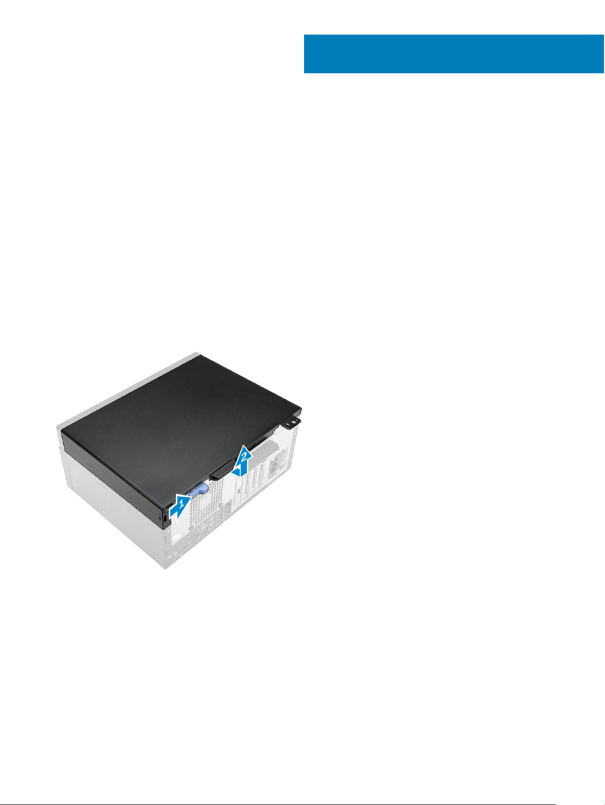
Removing the cover
1 Follow the procedure in Before Working Inside Your Computer.
2 To remove the cover:
a Slide the blue tab to release the cover from the computer [1].
b Slide the cover toward the back of the computer and lift it away from the computer [2].
2
Installing the cover
1 Place the cover on the computer and slide the cover forward until it clicks into place.
2 Follow the procedure in After Working Inside Your Computer.
Removing the bezel
1 Follow the procedure in Before Working Inside Your Computer.
2 Remove the cover.
3 To remove the front bezel:
Removing and installing components 7
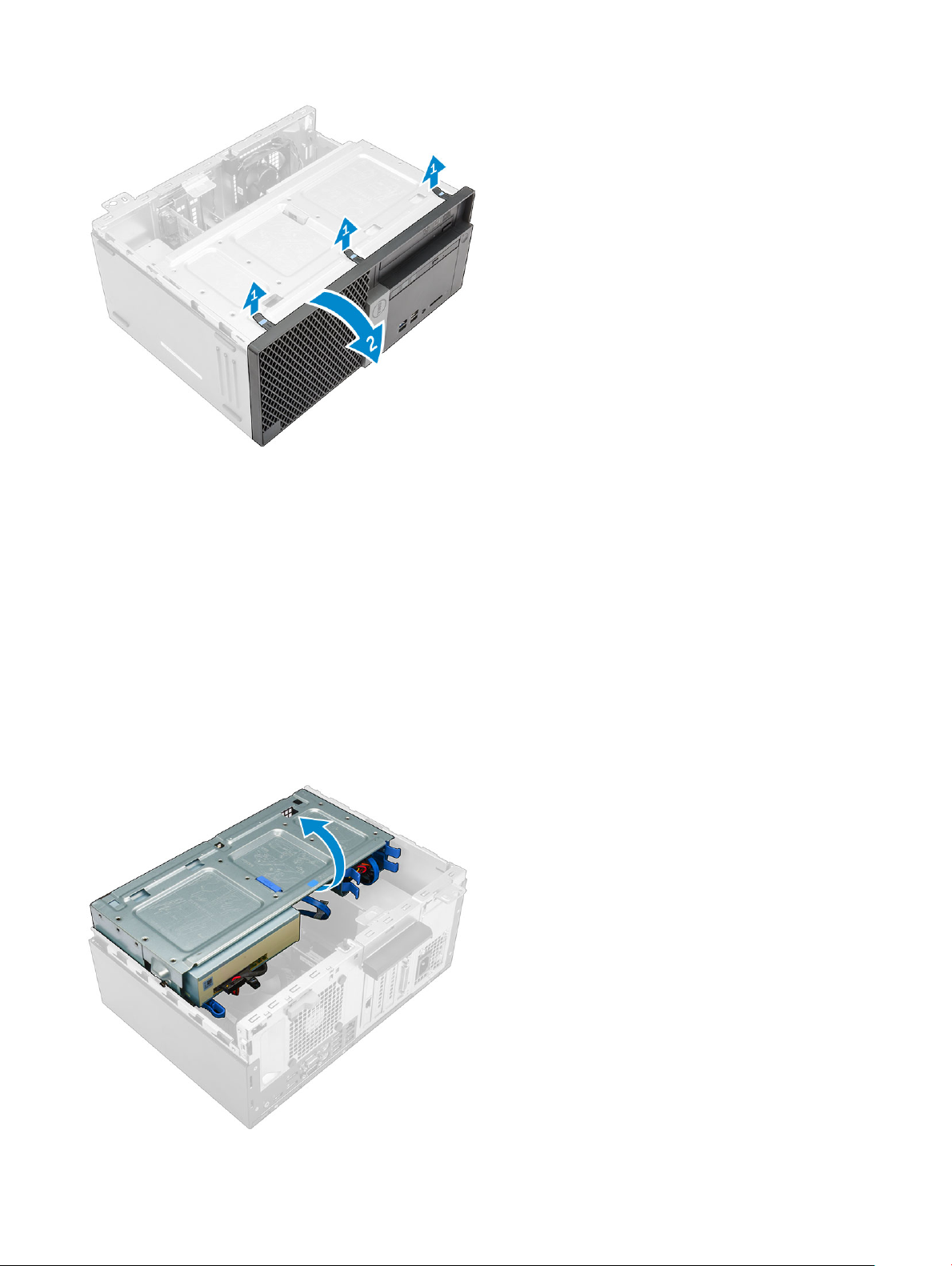
a Lift the tabs to release the front bezel from the computer.
b Remove the front bezel from the computer.
Installing the bezel
1 Insert the tabs on the bezel into the slots on the computer.
2 Press the bezel until the tabs clicks into place.
3 Install the cover.
4 Follow the procedure in After Working Inside Your Computer.
Opening the front bezel door
1 Follow the procedure in Before Working Inside Your Computer.
2 Remove the:
• cover
• bezel
3 Pull the front bezel door to open it.
8
Removing and installing components
CAUTION: The front bezel door opens only to a limited extent. See the printed label for the maximum permissible level.
Removing the hard drive assembly
1 Follow the procedure in Before Working Inside Your Computer.
2 Remove the:
• cover
• bezel
3 Open the front bezel door.
4 To remove the hard drive assembly:
a Disconnect the hard drive assembly cables from the connectors on the hard drive [1, 2].
b Press the blue tabs on both sides [3] and pull the hard drive assembly out of the computer [4].
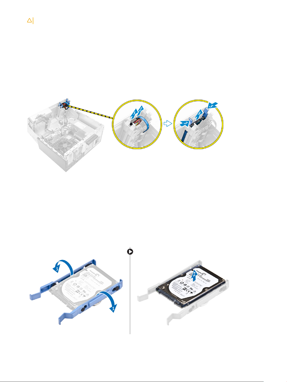
Removing the hard drive from the hard drive bracket
1 Follow the procedure in Before Working Inside Your Computer.
2 Remove the:
a cover
b bezel
c hard drive assembly
3 To remove the hard drive bracket:
a Pull one side of the hard drive bracket to disengage the pins on the bracket from the slots on the hard drive [1].
b Lift the hard drive out of the hard drive bracket [2].
Removing and installing components
9
Installing the hard drive into the hard drive bracket
1 Align and insert the pins on the hard drive bracket with the slots on one side of the hard drive.
2 Flex the other side of the hard drive bracket, and align and insert the pins on the bracket into the hard drive.
3 Install the:
a hard drive assembly
b bezel
c cover
4 Follow the procedure in After Working Inside Your Computer.
Installing the hard drive assembly
1 Insert the hard drive assembly into the slot on the computer until it clicks into place.
2 Close the front bezel door.
3 Connect the SATA cable and the power cable to the connectors on the hard drive.
4 Install the:
• bezel
• cover
5 Follow the procedure in After Working Inside Your Computer.
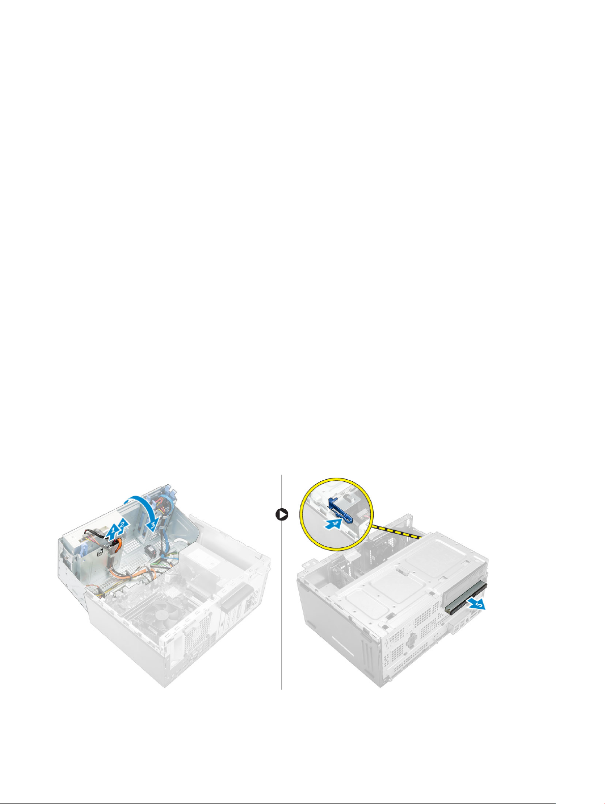
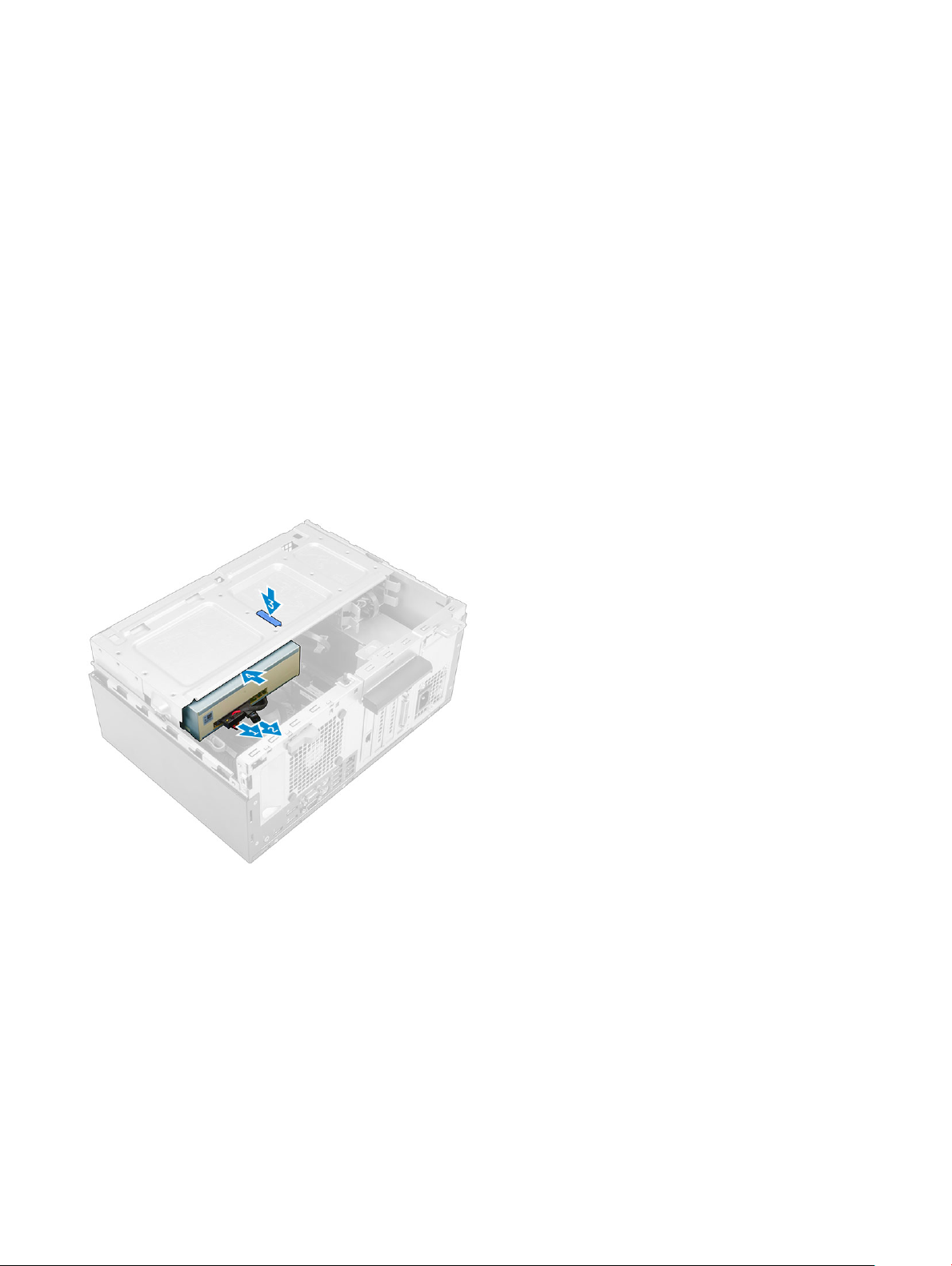
Removing the optical drive
1 Follow the procedure in Before Working Inside Your Computer.
2 Remove the:
• cover
• bezel
3 To remove the optical drive:
a Open the front bezel door.
b Disconnect the data cable and power cable from the connectors on the optical drive [1, 2].
c Close the front bezel door [3].
d Press the blue release tab [4] and slide the optical drive out of the computer [5].
10
Removing and installing components
Installing the optical drive
1 Insert the optical drive into the optical drive bay until it clicks into place.
2 Open the front bezel door.
3 Connect the data cable and power cable to the connectors on the optical drive.
4 Close the front bezel door.
5 Install the:
• bezel
• cover
6 Follow the procedure in After Working Inside Your Computer.
Removing the optical drive (3.5-inch)
1 Follow the procedure in Before Working Inside Your Computer.
2 Remove the:
• cover
• bezel
3 To remove the optical drive:
a Disconnect the data cable and power cable from the connectors on the optical drive [1, 2].
b Press the blue release tab [3] and slide the optical drive out of the optical drive bay [4].
Installing the optical drive (3.5-inch)
1 Insert the optical drive into the optical drive bay until it clicks into place.
2 Connect the data cable and power cable to the connectors on the optical drive.
3 Install the:
• bezel
• cover
4 Follow the procedure in After Working Inside Your Computer.
Installing the optional SSD card
1 Remove the:
Removing and installing components
11
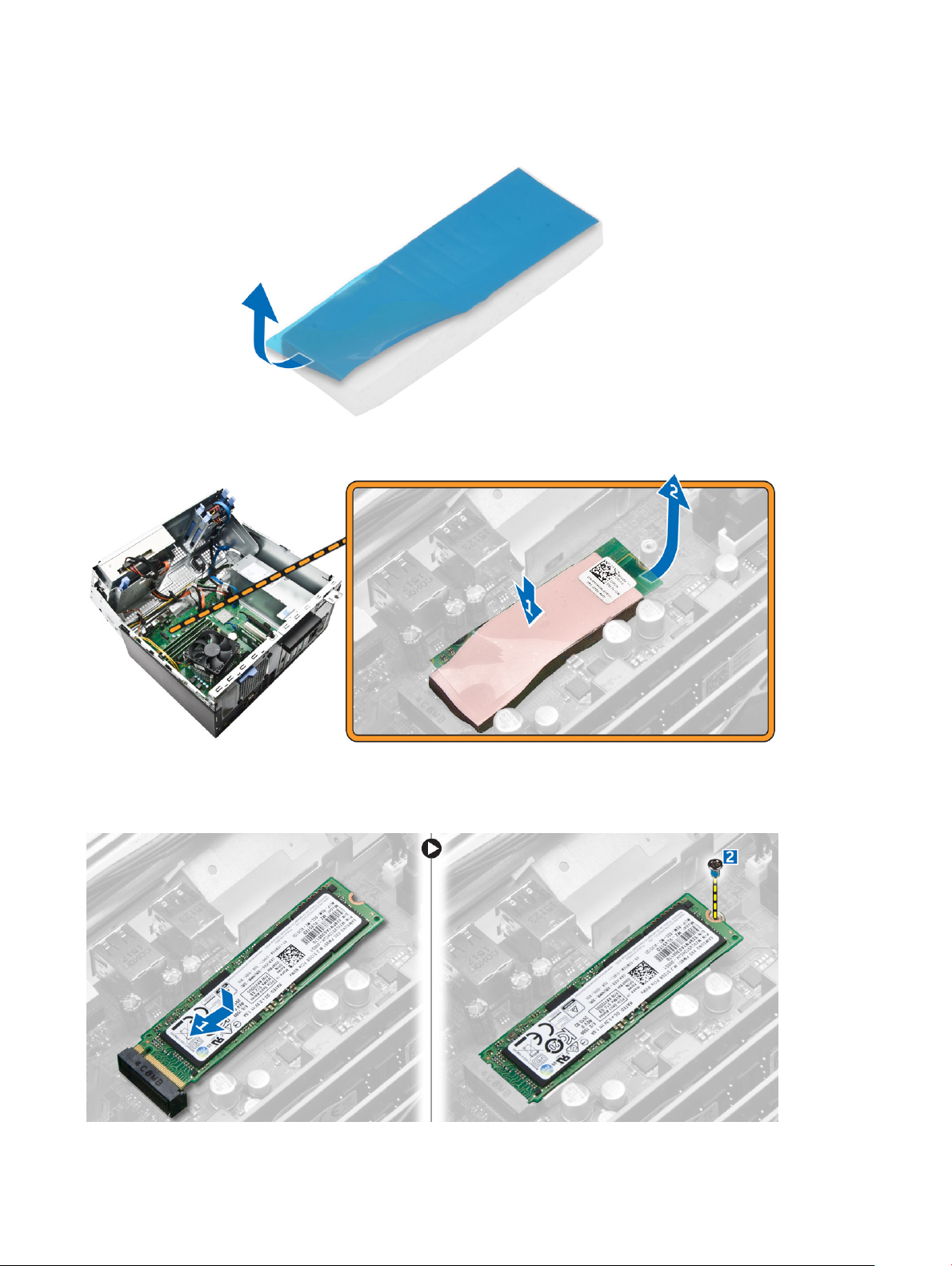
• cover
• bezel
2 Open the front bezel door.
3 Peel the adhesive tape (blue) from the rubber.
4 Place the rubber on the system board [1] and peel the adhesive tape (pink) from the rubber [2].
5 To install the SSD card:
a Connect the SSD card to the connector on the system board [1].
b Tighten the screw to secure the SSD card to the system board [2].
6 Close the front bezel door.
Removing and installing components
12
7 Install the:
a bezel
b cover
8 Follow the procedure in After Working Inside Your Computer.
Removing the optional SSD card
1 Follow the procedure in Before Working Inside Your Computer.
2 Remove the:
• cover
• bezel
3 Open the front bezel door.
4 Remove the screw that secures the SSD card to the system board.
5 Disconnect the SSD card from the connector on the system board.
6 Remove the rubber from the system board.
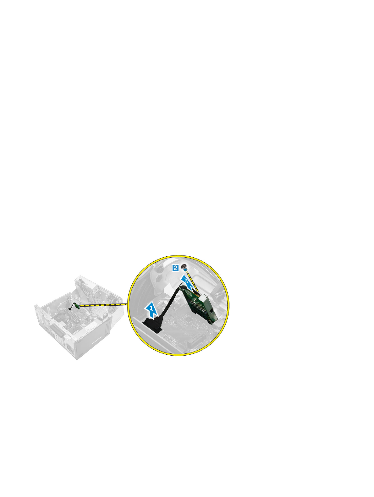
Removing the SD card reader
1 Follow the procedure in Before Working Inside Your Computer.
2 Remove the:
• cover
• bezel
3 Open the front bezel door.
4 To remove the SD card reader:
a Disconnect the SD card reader cable from the connector on the system board [1].
b Remove the screw that secures the SD card reader to the computer [2].
c Lift the SD card reader out of the computer [3].
Installing the SD card reader
1 Insert the SD card reader into the slot on the system board.
2 Tighten the screw to secure the SD card reader to the system board
3 Connect the SD card reader cable to the connector on the system board.
4 Close the front bezel door.
5 Install the:
a bezel
b cover
Removing and installing components
13
6 Follow the procedure in After Working Inside Your Computer.
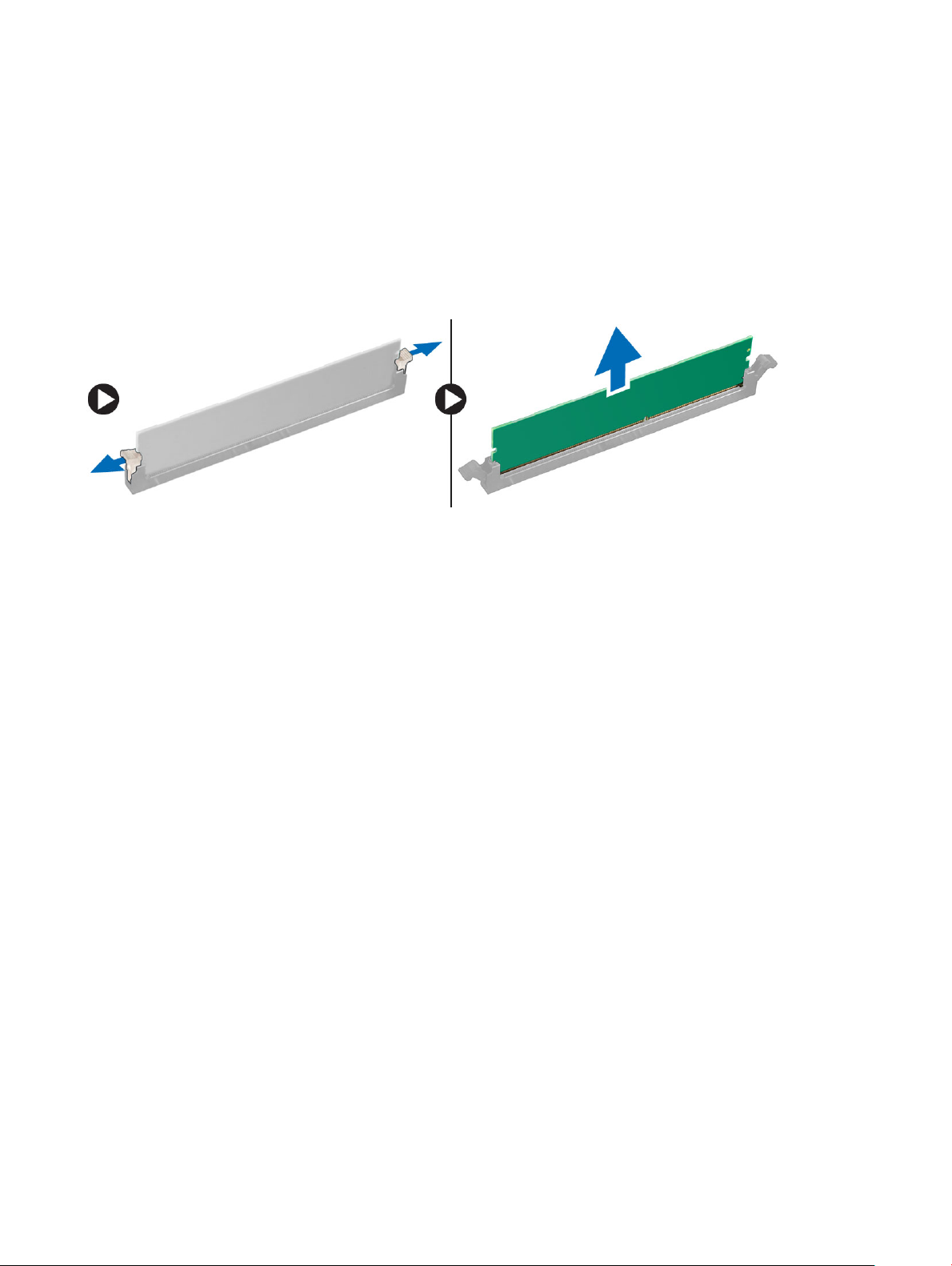
Removing the memory module
1 Follow the procedure in Before Working Inside Your Computer.
2 Remove the:
• cover
• bezel
3 Open the front bezel door.
4 To remove the memory module:
a Press the memory module retention tabs on both sides of the memory module.
b Lift the memory module from the memory module connector on the system board.
Installing the memory module
1 Align the notch on the memory module with the tab on the memory module connector.
2 Insert the memory module into the memory module socket.
3 Press the memory module until the memory module retention tabs click into place.
4 Close the front bezel door.
5 Install the:
a cover
b bezel
6 Follow the procedure in After Working Inside Your Computer.
Removing the PCIe expansion card
1 Follow the procedure in Before Working Inside Your Computer.
2 Remove the:
• cover
• bezel
3 Open the front bezel door.
4 To remove the PCIe expansion card:
a Pull the release latch to unlock the PCIe expansion card [1].
b Push the release tab [2] and lift the PCIe expansion card out of the computer [3].
Removing and installing components
14
 Loading...