

Dell NVDIMM-N User Manual

Dell EMC NVDIMM-N Persistent Memory
User Guide
Feb rua ry 202 1
Rev . A 11

Notes, cautions, and warnings
NOTE: A NOTE indicates important information that helps you make better use of your product.
CAUTION: A CAUTION indicates either potential damage to hardware or loss of data and tells you how to avoid
the problem.
WARNING: A WARNING indicates a potential for property damage, personal injury, or death.
© 2017 - 2021 Dell Inc. or its subsidiaries. All rights reserved. Dell, EMC, and other trademarks are trademarks of Dell Inc. or its subsidiaries.
Other trademarks may be trademarks of their respective owners.

Contents
Chapter 1: Introduction................................................................................................................. 5
Chapter 2: Change list...................................................................................................................6
Chapter 3: NVDIMM-N Overview................................................................................................... 7
Normal Operation.................................................................................................................................................................7
Backup to Flash....................................................................................................................................................................8
Restore from Flash..............................................................................................................................................................9
Chapter 4: Hardware....................................................................................................................10
Server Hardware Configuration......................................................................................................................................10
Modular Chassis Hardware Configuration....................................................................................................................14
NVDIMM-N Module Details............................................................................................................................................. 14
Battery..................................................................................................................................................................................15
Minimum Platform Firmware Versions.......................................................................................................................... 17
Chapter 5: BIOS...........................................................................................................................18
BIOS Configuration Settings for NVDIMM-N............................................................................................................. 18
BIOS Error Messages....................................................................................................................................................... 22
Chapter 6: iDRAC NVDIMM-N Management................................................................................. 24
iDRAC Graphical User Interface.................................................................................................................................... 24
NVDIMM-N Status......................................................................................................................................................24
BBU Status................................................................................................................................................................... 25
Log Messaging Errata.................................................................................................................................................26
Remote Management....................................................................................................................................................... 26
NVDIMM-N Error Reporting........................................................................................................................................... 26
Chapter 7: Server Behavior with NVDIMM-Ns..............................................................................29
Shutdown............................................................................................................................................................................ 29
Boot...................................................................................................................................................................................... 30
Automatic Shutdown and Save..................................................................................................................................... 30
Chapter 8: DIMM Configuration Changes..................................................................................... 31
Chapter 9: Windows.................................................................................................................... 32
BIOS Requirements...........................................................................................................................................................32
Set Up.................................................................................................................................................................................. 32
Windows Drivers................................................................................................................................................................32
Storage Class Memory in Windows Server 2016.......................................................................................................33
Device manager........................................................................................................................................................... 33
Identifying the right NVDIMM-N disks...................................................................................................................33
NVDIMM-N health status and properties..............................................................................................................36
Contents 3

Block Mode................................................................................................................................................................... 36
DAX Mode..................................................................................................................................................................... 36
Storage Spaces Support ...........................................................................................................................................37
Operational and Diagnostics Logging information............................................................................................... 37
Storage Class Memory in Windows Server 2019....................................................................................................... 37
NVDIMM-N FW Requirement................................................................................................................................... 37
Driver Architecture Overview...................................................................................................................................37
New features in Windows Server 2019 Label support and Namespace management............................... 38
PowerShell Cmdlets....................................................................................................................................................40
NVDIMM-N Interleaving............................................................................................................................................ 40
Configuring NVDIMM-N for Hyper-V Virtual Machines..................................................................................... 41
NVDIMM-N RO Behavior........................................................................................................................................... 41
Windows Errata.................................................................................................................................................................. 41
Chapter 10: Linux........................................................................................................................ 43
Identify and Configure PMEM —Persistent Memory Device................................................................................ 43
Installation........................................................................................................................................................................... 44
Verify Existing Filesystem............................................................................................................................................... 44
Read-Only Mode NVDIMM-N........................................................................................................................................ 44
Interleave.............................................................................................................................................................................44
Interleave Setup...........................................................................................................................................................44
Interleave Verification................................................................................................................................................ 45
Read Only Mode NVDIMM-N................................................................................................................................... 45
Management Utility ......................................................................................................................................................... 46
ndctl................................................................................................................................................................................ 46
mdadm............................................................................................................................................................................ 47
RHEL 7.6 features............................................................................................................................................................. 47
Linux Errata.........................................................................................................................................................................48
Chapter 11: ESXi.......................................................................................................................... 49
Set up...................................................................................................................................................................................49
Storage................................................................................................................................................................................ 49
Namespaces................................................................................................................................................................. 50
Interleave sets..............................................................................................................................................................50
Datastore........................................................................................................................................................................51
Supported Guest OSes with NVDIMM support.........................................................................................................52
Overall Health Status ...................................................................................................................................................... 52
Operational and Diagnostics Logging information.....................................................................................................52
Outdated firmware......................................................................................................................................................53
NVDIMM-N Errors............................................................................................................................................................ 53
ESXi Errata..........................................................................................................................................................................54
Chapter 12: General Errata.......................................................................................................... 55
4
Contents
Introduction
DellEMC’s NVDIMM-N Persistent Memory is a disruptive Storage Class Memory technology that enables unprecedented
performance improvement over legacy storage technologies. Each NVDIMM-N provides 16GB of nonvolatile memory and has
the same form factor as a standard 288-Pin DDR4 DIMM. The NVDIMM-N resides in a standard CPU memory slot, placing
data close the processor. With its ability to operate at 2666MT/s DDR4 data rates, the NVDIMM-N takes full advantage of the
high bandwidth and extremely low latency that is characteristic of the memory bus. For comparison, the table below provides
approximate data access times for DDR4 relative to other server storage media.
Table 1. Storage Technology
Storage Technology Data Access Time
15K SAS Disk ~ 6,000,000 ns
SATA SSD ~ 120,000 ns
NVMe SSD ~ 60,000 ns
DDR4 NVDIMM-N ~ 150 ns
1
This document provides an overview of the DellEMC NVDIMM-N Persistent Memory solution. It is intended to help the user
with initial set-up and configuration, providing information on system behavior when NVDIMM-Ns are installed. This document
will also help the user to become familiar with NVDIMM-N manageability and error handling. And lastly, it introduces the user to
NVDIMM-N basic setup and configuration in a variety of supported operating systems.
Introduction 5

Change list
Table 2. Change list
Version Changes
A00 Original Version
A01 Added ESXi 6.7 support information. Removed Linux errata that is no longer
applicable. Edits to remainder of document for clarity.
2
A02
A03
A04
A09 Updated Windows Errata
A10 Added General Errata
A11 Fixed hyperlinks in the RHEL 7.6 Features chapter
Added Modular Server specific information, support for R840, R940xa, changes to the
BBU LED behavior and edits to the remainder of document for clarity.
NVDIMM-N supported on RHEL 7.5
Added minimum supported platform firmware versions
Support for Windows 2019, RHEL 7.6 and ESXi 6.7 U1.
Windows 2019 new features and NVDIMM-N RO behavior
RHEL 7.6 features and bug fix
Updated Linux Errata
Node Interleaving (RDIMM) unsupported on NVDIMM-N configurations
6 Change list
3
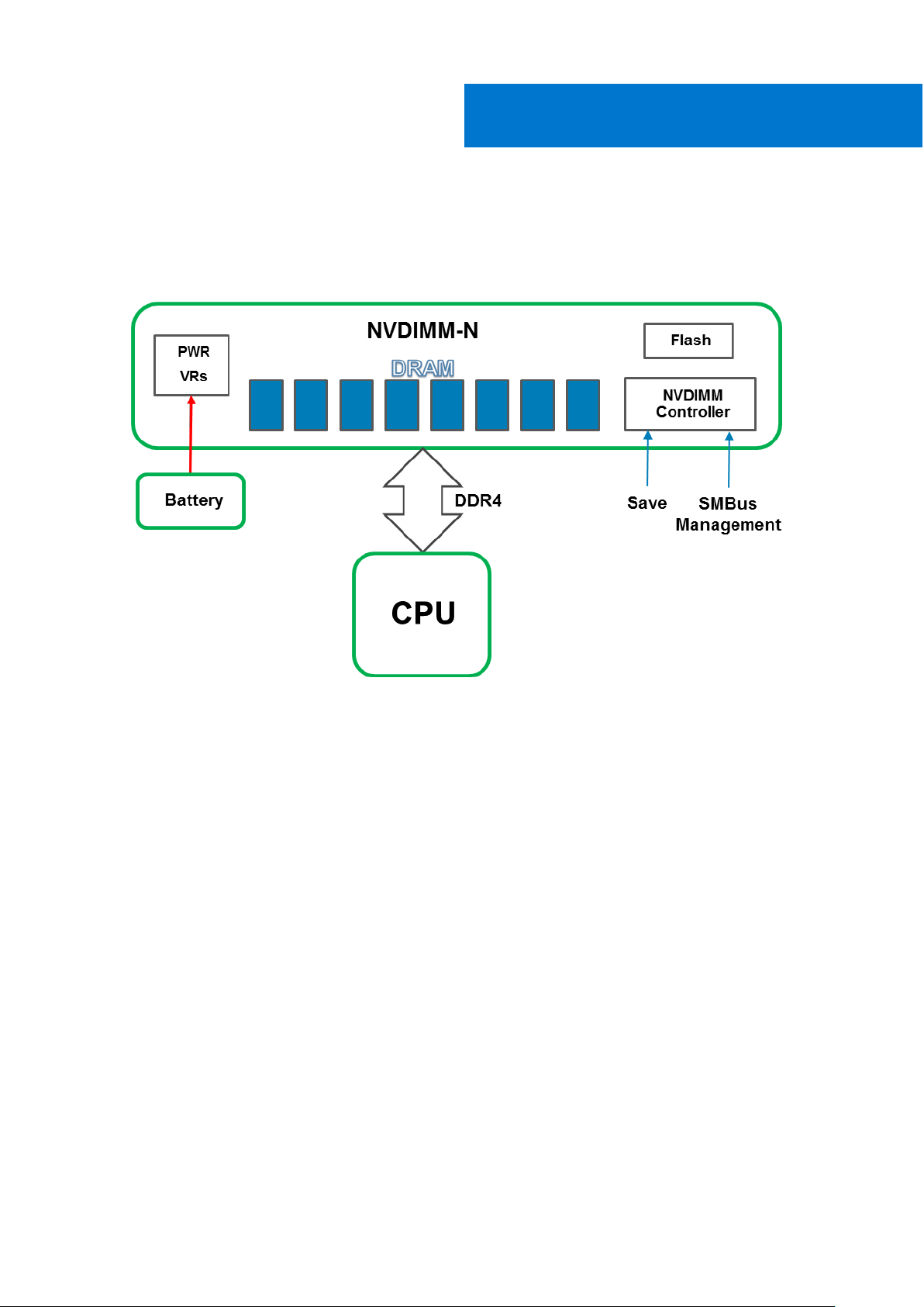
NVDIMM-N Overview
The Figure below is an overview of the NVDIMM-N showing its main components and system interfaces. Core to the NVDIMMN are the DDR4 DRAM devices that allow the NVDIMM-N to operate as an RDIMM. The components that allow the NVDIMM-N
to persist data are the Controller, Flash, and Power Voltage Regulators that are also integrated on the DIMM.
Figure 1. NVDIMM-N Overview
Topics:
• Normal Operation
• Backup to Flash
• Restore from Flash
Normal Operation
NVDIMM-Ns are installed in server memory slots. From a hardware perspective, the NVDIMM-Ns appear to the processor as
standard DDR4 RDIMMs. They are initialized during BIOS POST, and the CPU can access DRAM data on the NVDIMM-N using
standard DDR4 memory load/store transactions.
NVDIMM-N Overview 7
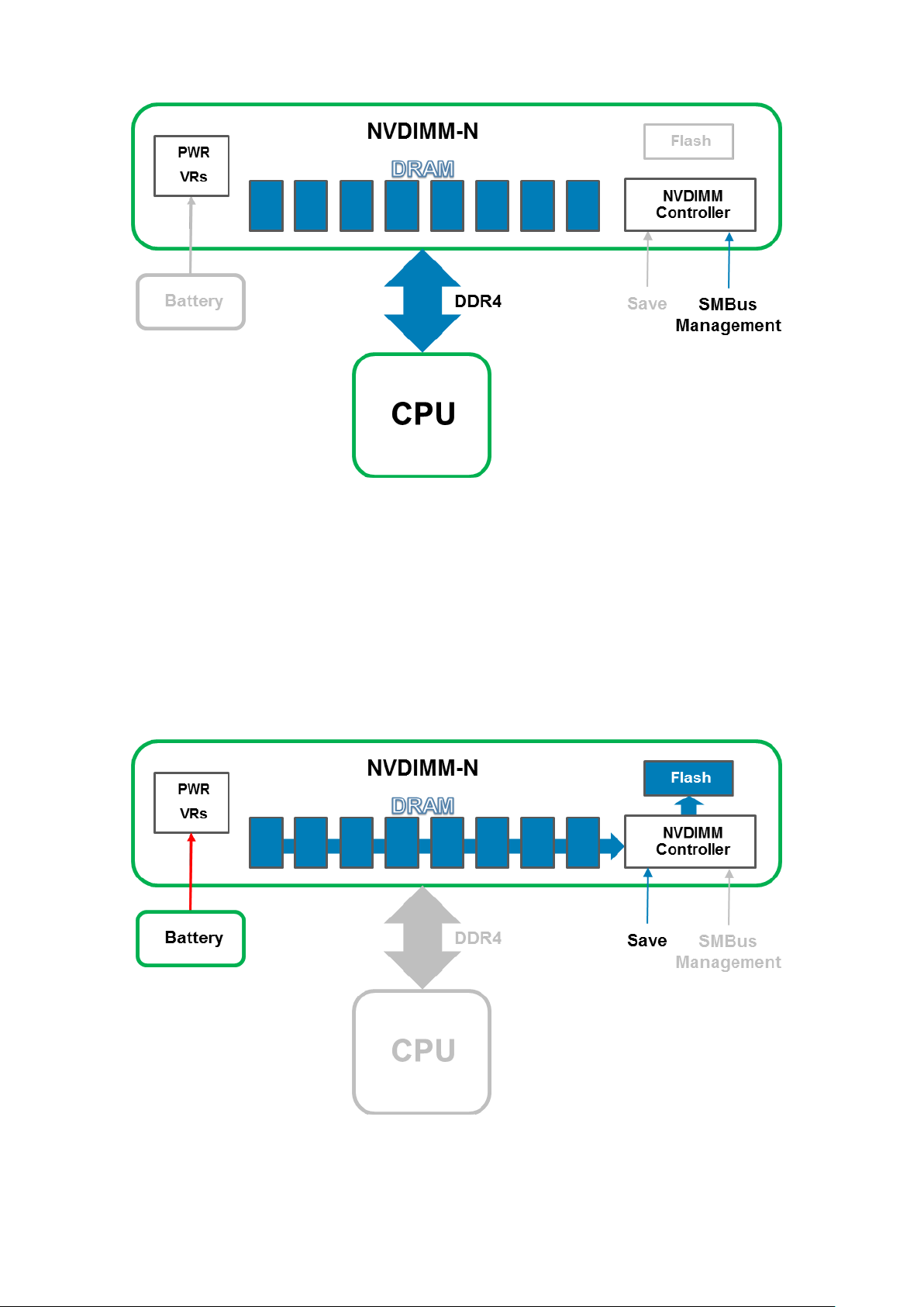
Figure 2. NVDIMM-N Normal Operation
Backup to Flash
In the event of a server shutdown, cold reboot, or power loss, a Save signal is sent to the NVDIMM-N Controller which then
triggers the NVDIMM-N Controller to backup all its DRAM contents to its onboard flash storage. The NVDIMM-N Save event
is triggered anytime the server is about to power down and power loss to NVDIMM-Ns is imminent. The backup process
takes approximately one minute to complete. This duration is independent of the number of NVDIMM-Ns installed in the server
because Saves occur in parallel across all NVDIMM-Ns.
A Battery provides backup power to the NVDIMM-N so that it can complete the backup operation even after an power
loss. When the Save operation is complete, the Battery is deactivated to allow the server and NVDIMM-Ns to power down
completely.
Figure 3. Save Operation
8
NVDIMM-N Overview
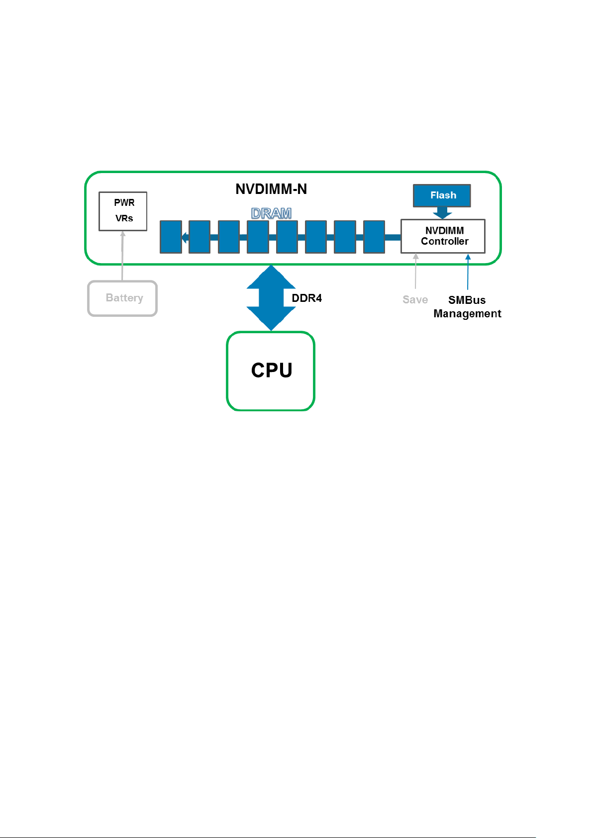
Restore from Flash
On server power-up, BIOS re-initializes the DRAM on the NVDIMM-N. BIOS commands the NVDIMM-N Controller using the
SMBus Management Interface to restore its DRAM contents from Flash. The restore process takes approximately one minute to
complete. This duration is independent of the number of NVDIMM-Ns installed in the server because Restores occur in parallel
across all NVDIMM-Ns. BIOS then exposes the NVDIMM-N to the Server OS as Persistent Memory. Note that Persistent
Memory is distinct from System Memory which is required for normal OS operation. Please refer to the respective OS Sections
for more details on OS support of Persistent Memory.
Figure 4. Restore Operation
NVDIMM-N Overview
9
4
Hardware
Topics:
• Server Hardware Configuration
Modular Chassis Hardware Configuration
•
• NVDIMM-N Module Details
• Battery
• Minimum Platform Firmware Versions
Server Hardware Configuration
NVDIMM-Ns are currently supported in the T640, R640,R740/R740XD, R840, R940, R940xa, MX740c and MX840c PowerEdge
Servers. Each server supports from 1x to a maximum of 12x 16GB NVDIMM-Ns for a total max persistent memory capacity of
192GB. Table 1 below provides the NVDIMM-N configurations that have been validated and are fully supported for 2-Socket
server configurations. For 4-Socket configurations in the R840, R940, R940xa and MX840c PowerEdge Server, NVDIMM-Ns
are only supported in CPU 1 and CPU 2 memory slots. Table 2 below provides the NVDIMM-N configurations that have been
validated and are fully supported on the R840, R940, R940xa and MX840c 4-Socket configurations.
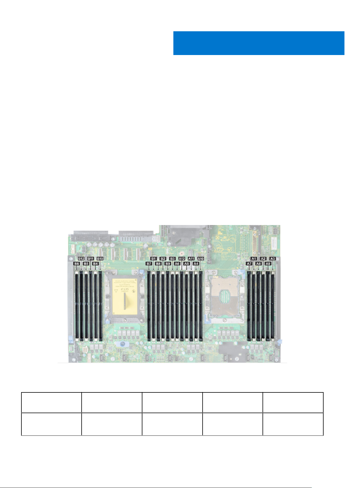
Refer to Figure 5 for the R740/R740XD CPU and DIMM slot locations as an example. Please see the respective server’s
Installation and Service Manual for memory installation guidelines.
Figure 5. R740/R740XD Memory Layout
Table 3. Supported NVDIMM-N Configurations, 2-Socket
NVDIMM-N NVDIMM-N Capacity RDIMMs RDIMM
Capacity
1x 16GB 12x 16GB 192GB RDIMMs: A1-A6, B1-B6
10 Hardware
DIMM Population
Locations
NVDIMM-N: A7

Table 3. Supported NVDIMM-N Configurations, 2-Socket (continued)
NVDIMM-N NVDIMM-N Capacity RDIMMs RDIMM
Capacity
1x 16GB 12x 32GB 384GB RDIMMs: A1-A6, B1-B6
1x 16GB 23x 32GB 736GB RDIMMs: A1-A12, B1-
2x 32GB 12x 16GB 192GB RDIMMs: A1-A6, B1-B6
2x 32GB 12x 32GB 384GB RDIMMs: A1-A6, B1-B6
2x 32GB 22x 32GB 704GB RDIMMs: A1-A11, B1-B11
4x 64GB 12x 16GB 192GB RDIMMs: A1-A6, B1-B6
DIMM Population
Locations
NVDIMM-N: A7
B11
NVDIMM-N: B12
NVDIMM-Ns: A7, B7
NVDIMM-Ns: A7, B7
NVDIMM-Ns: A12, B12
NVDIMM-Ns: A7-A8,
B7-B8
4x 64GB 12x 32GB 384GB RDIMMs: A1-A6, B1-B6
NVDIMM-Ns: A7-A8,
B7-B8
4x 64GB 20x 32GB 640GB RDIMMs: A1-A10, B1-
B10
NVDIMM-Ns: A11-A12,
B11-B12
6x 96GB 12x 16GB 192GB RDIMMs: A1-A6, B1-B6
NVDIMM-Ns: A7-A9,
B7-B9
6x 96GB 12x 32GB 384GB RDIMMs: A1-A6, B1-B6
NVDIMM-Ns: A7-A9,
B7-B9
6x 96GB 18x 32GB 576GB RDIMMs: A1-A9, B1-B9
NVDIMM-Ns: A10-A12,
B10-B12
12x 192GB 12x 16GB 192GB RDIMMs: A1-A6, B1-B6
NVDIMM-Ns: A7-A12,
B7-B12
12x 192GB 12x 32GB 384GB RDIMMs: A1-A6, B1-B6
NVDIMM-Ns: A7-A12,
B7-B12
Note: While other configurations may work, they have not been fully validated and are not currently supported by DellEMC.
Hardware
11
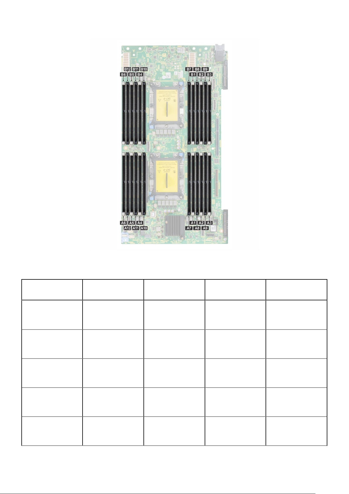
Figure 6. MX740c Memory Layout
Table 4. Supported NVDIMM-N Configurations, R940, MX840c 4-Socket 4-Socket
NVDIMM-N NVDIMM-N Capacity RDIMMs RDIMM
Capacity
1x 16GB 24x 16GB 384GB RDIMMs: A1-A6, B1-B6,
1x 16GB 24x 32GB 768GB RDIMMs: A1-A6, B1-B6,
1x 16GB 47x 32GB 1504GB RDIMMs: A1-A12, B1-
2x 32GB 24x 16GB 384GB RDIMMs: A1-A6, B1-B6,
2x 32GB 24x 32GB 768GB RDIMMs: A1-A6, B1-B6,
DIMM Population
Locations
C1-C6, D1-D6
NVDIMM-N: A7
C1-C6, D1-D6
NVDIMM-N: A7
B11, C1-C12, D1-D12
NVDIMM-N: B12
C1-C6, D1-D6
NVDIMM-Ns: A7, B7
C1-C6, D1-D6
NVDIMM-Ns: A7, B7
12 Hardware

Table 4. Supported NVDIMM-N Configurations, R940, MX840c 4-Socket 4-Socket (continued)
NVDIMM-N NVDIMM-N Capacity RDIMMs RDIMM
Capacity
2x 32GB 46x 32GB 1472GB RDIMMs: A1-A11, B1-
4x 64GB 24x 16GB 384GB RDIMMs: A1-A6, B1-B6,
4x 64GB 24x 32GB 768GB RDIMMs: A1-A6, B1-B6,
4x 64GB 44x 32GB 1408GB RDIMMs: A1-A10, B1-
6x 96GB 24x 16GB 384GB RDIMMs: A1-A6, B1-B6,
DIMM Population
Locations
B11, C1-C12, D1-D12
NVDIMM-Ns: A12, B12
C1-C6, D1-D6
NVDIMM-Ns: A7-A8,
B7-B8
C1-C6, D1-D6
NVDIMM-Ns: A7-A8,
B7-B8
B10, C1-C12, D1-D12
NVDIMM-Ns: A11-A12,
B11-B12
C1-C6, D1-D6
NVDIMM-Ns: A7-A9,
B7-B9
6x 96GB 24x 32GB 768GB RDIMMs: A1-A6, B1-B6,
C1-C6, D1-D6
NVDIMM-Ns: A7-A9,
B7-B9
6x 96GB 42x 32GB 1344GB RDIMMs: A1-A9, B1-B9,
C1-C12, D1-D12
NVDIMM-Ns: A10-A12,
B10-B12
12x 192GB 24x 16GB 384GB RDIMMs: A1-A6, B1-B6,
C1-C6, D1-D6
NVDIMM-Ns: A7-A12,
B7-B12
12x 192GB 24x 32GB 768GB RDIMMs: A1-A6, B1-B6,
C1-C6, D1-D6
NVDIMM-Ns: A7-A12,
B7-B12
12x 192GB 36x 32GB 1152GB RDIMMs: A1-A6, B1-B6,
C1-C12, D1-D12
NVDIMM-Ns: A7-A12,
B7-B12
NOTE:
1. NVDIMM-Ns are not supported in CPU Sockets 3 and 4 memory slots
Hardware 13
2. While other configurations may work, they have not been fully validated and are not currently supported by DellEMC.
Modular Chassis Hardware Configuration
The MX7000 Modular chassis currently offers two different servers that support NVDIMM-N: MX740c (2-socket) and MX840c
(4-socket). In order for an power loss condition to be detected, the chassis must have at least one Management Module
installed. While not a requirement for NVDIMM-N support, dual Management Modules provide additional redundancy and
robustness to the NVDIMM-N solution.
If a user is operating a chassis with NVDIMM-N equipped servers and a Management Module firmware update is performed, it
is recommended that the chassis be equipped with two Management Modules. If the chassis has a single Management Module,
the NVDIMM-Ns in the server may be placed in read-only mode during the Management Module upgrade.
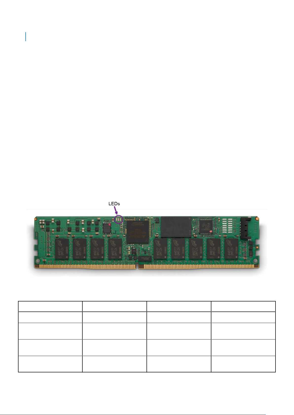
NVDIMM-N Module Details
Figure 6 is a picture of a typical NVDIMM-N, and it shows the location of status LEDs on the NVDIMM-N. Table 3 describes the
NVDIMM-Ns LED behavior during different modes of operation.
The DIMM has the following key features:
● JEDEC compliant DDR4 288-pin NVDIMM-N
● 16GB RDIMM, PC4-2666
● SLC Flash for backup
● In-system health monitoring and alert
● On-board I2C temperature sensor with integrated SPD EEPROM
Figure 7. NVDIMM-N
Table 5. : NVDIMM-N LED Behavior
NVDIMM-N Operation Green LED Blue LED Amber LED
Powered Off Off Off Off
NVDIMM-N going through
power-on and initialization
NVDIMM-N is operating
normally
Save of Restore Operation in
progress
14 Hardware
On Off On
On Slow Blink (every 15 seconds) Off
On Fast Blink Off

Battery
A battery is required to provide backup power to copy contents from DRAM to flash. Although JEDEC based NVDIMM-Ns can
utilize Super Caps as backup power, DellEMC’s battery is a centralized power solution that provides a more compact, reliable,
and integrated power source. Power delivery is integrated into the system board, and does not require individual cables to each
NVDIMM-N that is typical of Super Cap based solutions.
On first detection of an power loss, the server activates the battery and triggers the NVDIMM-N to save its DRAM contents to
flash. The Save process takes approximately a minute to complete in the T640, R640, R740/R740XD, R840, R940 and R940xa
servers and 140 seconds to complete in the MX740c and MX840c servers. During this time the battery is required to provide
power for backup. The battery supplies power only to server sub-systems that must be powered for the save to complete. All
other subsystems are powered down or placed into a low power state to conserve battery life. After the save completes, the
battery is deactivated, and the server is allowed to power down completely. In modular chassis, the batteries also provide power
to the system fans to provide cooling during the NVDIMM save after an power loss event.
Table 6. Battery LED Behavior
Battery Operation Green LED
Powered Off Off
Idle (not charging and not enabled while the server is on) Off
Maintenance Charging On
Critical Charging (battery capacity is below minimum required for NVDIMM-N Save, server is
powered on)
Battery Enabled and Discharging (Power loss detected, Battery supplying power for NVDIMMN Save operation)
If a battery is not installed or not fully charged, BIOS will restore the NVDIMM-N DRAM contents from its onboard flash, but
BIOS will keep the NVDIMM-N in Read-Only mode. This allows OS and applications to have access to NVDIMM-N data, and at
the same time protect the NVDIMM-N from potential data loss due to power loss.
The NVDIMM-N battery is not hot swappable. To prevent data loss and potential damage to your system, ensure that the
system, LEDs on the system, LEDs on NVDIMM-N, and LEDs on NVDIMM-N battery are turned off before installing or removing
the NVDIMM-N Battery.
Figure 7 below shows the system board connections for the NVDIMM-N Battery cables in the R740/R740XD (Items 36 and 38).
Figure 8 shows how to install and mount the battery in the R740/R740XD. Please refer to each server’s Installation and Service
Manual for detailed instructions on how to install or remove the battery.
Blinking
Blinking
Hardware
15
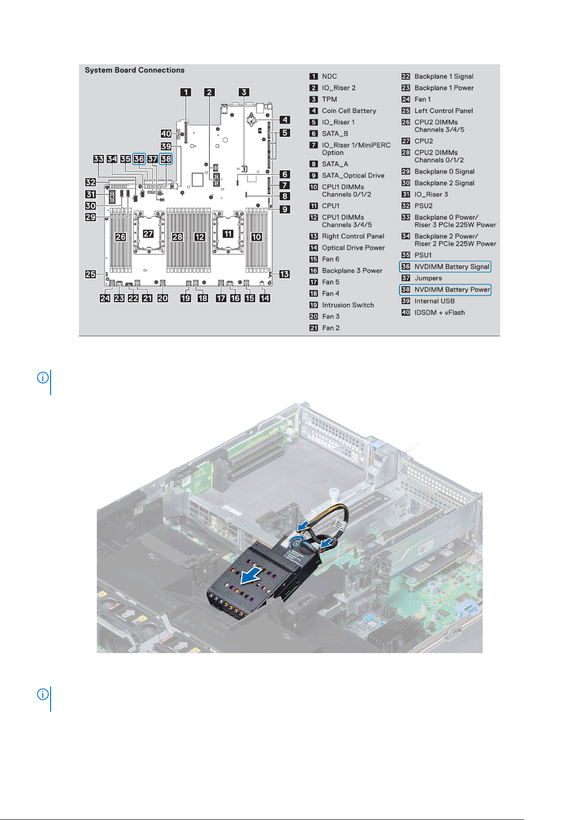
Figure 8. R740/R740XD System Board Connections
NOTE:
Connector locations will be different for each server. Please refer to your particular server’s Installation and Service
Manual for more information.
Figure 9. R740 Battery Installation Instructions
Battery installation locations will be different for each server. Please refer to your particular Server’s Installation and
NOTE:
Service Manual for instructions.
16 Hardware

Minimum Platform Firmware Versions
For NVDIMM-N modules to be functional on PowerEdge servers, the minimum platform firmware versions are required to be as
follows:
● BIOS: 1.1.7
● iDRAC: 3.00.00.00
NOTE: Certain operating systems require specific minimum versions of BIOS, NVDIMM-N and/or iDRAC firmware. Please
refer to the individual sections of the operating systems for more details.
Hardware 17
 Loading...