

Dell Networking S3100 Series Getting Started Manual

Dell Networking S3100 Series
Getting Started Guide
Regulatory Model: S3100

Notes, cautions, and warnings
NOTE: A NOTE indicates important information that helps you make better use of your computer.
CAUTION: A CAUTION indicates either potential damage to hardware or loss of data and tells you
how to avoid the problem.
WARNING: A WARNING indicates a potential for property damage, personal injury, or death.
Copyright © 2015 Dell Inc. All rights reserved. This product is protected by U.S. and international copyright and
intellectual property laws. Dell™ and the Dell logo are trademarks of Dell Inc. in the United States and/or other
jurisdictions. All other marks and names mentioned herein may be trademarks of their respective companies.
2015 - 10
Rev. A00

1
About this Guide
This document is intended as a Getting Started Guide to get new systems up and running and ready for
configuration.
For more details about S3100 series installation and software configuration, see the following
information, available on the Dell Networking Support website (http://www.dell.com/support).
• The Dell Networking S3100 Series Installation Guide describes installation and replacement
procedures.
• The Dell Configuration Guide for the S3100 Series describes software configuration.
• The Dell Command Line Reference Guide for the S3100 Series provides command line interface (CLI)
information.
• The Dell Networking S3100 Series Release Notes provide information about upgrading the S3100
series.
About this Guide
3

2
S3100 Series Hardware Overview
This section contains basic information about the S3100 series, including descriptions of features, I/O and
PSU sides, power supplies, fans, and light emitting diode (LED) status.
Product Description
The S3100 series is a low-cost wireless closet switch/router product for copper connections to 1G
endpoints with Power over Ethernet plus (PoE+) capability on 1G access ports. The series includes
capabilities for 1/10GE switching with 1G copper links for campus network endpoints and 10G ports for
uplinks to core/aggregation switches. Each of the platforms also includes a 20G expansion slot that
supports an optional small form-factor pluggable plus (SFP+) or 10GBase-T module. The series has four
platforms. For the two PoE platforms, you can stack up to six switches to operate as a single unit.
The S3124 platform includes the following features:
• Twenty-four Gigabit Ethernet 10/100/1000BASE-T RJ-45 ports that support auto-negotiation for
speed, flow control, and duplex.
• Two combo SFP ports.
• Two SFP+ 10G ports.
The S3124F platform includes the following features:
• Twenty-four Gigabit Ethernet 100BASEFX/1000BASE-X SFP ports.
• Two 1G copper combo ports.
• Two SFP+ 10G ports.
The S3124P platform includes the following features:
• Twenty-four Gigabit Ethernet 10/100/1000BASE-T RJ-45 ports for copper that support autonegotiation for speed, flow control, and duplex.
• Two combo SFP ports.
• Two SFP+ 10G ports.
• Supports PoE+.
• Two fixed mini Serial Attached SCSI (mini-SAS) stacking ports HG[21] to connect up to six switches.
For the S3124, S3124F, and S3124P platforms, the port numbering is as follows:
• Regular ports (I/O side) are numbered one to twenty-four.
• Combo ports (I/O side) are numbered twenty-three and twenty-four.
• SFP+ ports (I/O side) are numbered twenty-five and twenty-six.
• Module ports (PSU side) are numbered twenty-seven and twenty-eight.
• Stacking ports (PSU side) are numbered twenty-nine and thirty.
The S3148P platform includes the following features:
4
S3100 Series Hardware Overview
• Forty-eight Gigabit Ethernet 10BASE-T, 100BASE-TX, 1000BASE-T RJ-45 ports that support autonegotiation for speed, flow control, and duplex.
• Two combo SFP ports.
• Two SFP+ 10G ports.
• Supports PoE+.
• Two fixed mini-SAS stacking ports HG[21] to connect up to six switches.
For the S3148P platform, the port numbering is as follows:
• Regular ports (I/O side) are numbered one to forty-eight.
• Combo ports (I/O side) are numbered forty-seven and forty-eight.
• SFP+ ports (I/O side) are numbered forty-nine and fifty.
• Module ports (PSU side) are numbered fifty-one and fifty-two.
• Stacking ports (PSU side) are numbered fifty-three and fifty-four.
All S3100 series platforms have the following features:
• One 20G expansion slot for modules (SFP+ [fiber] or 10GBase-T [copper RJ–45]).
• Front panel out-of-band (OOB) management port.
• External serial RS232 port (RJ–45 type).
• One universal serial bus (USB-A) port.
• Hot-swappable redundant power supply unit (PSU).
• Hot-swappable fan tray.
• Standard 1U chassis high.
NOTE: Dell-qualified SFP+ transceivers are sold separately.
S3124 Platform I/O Side
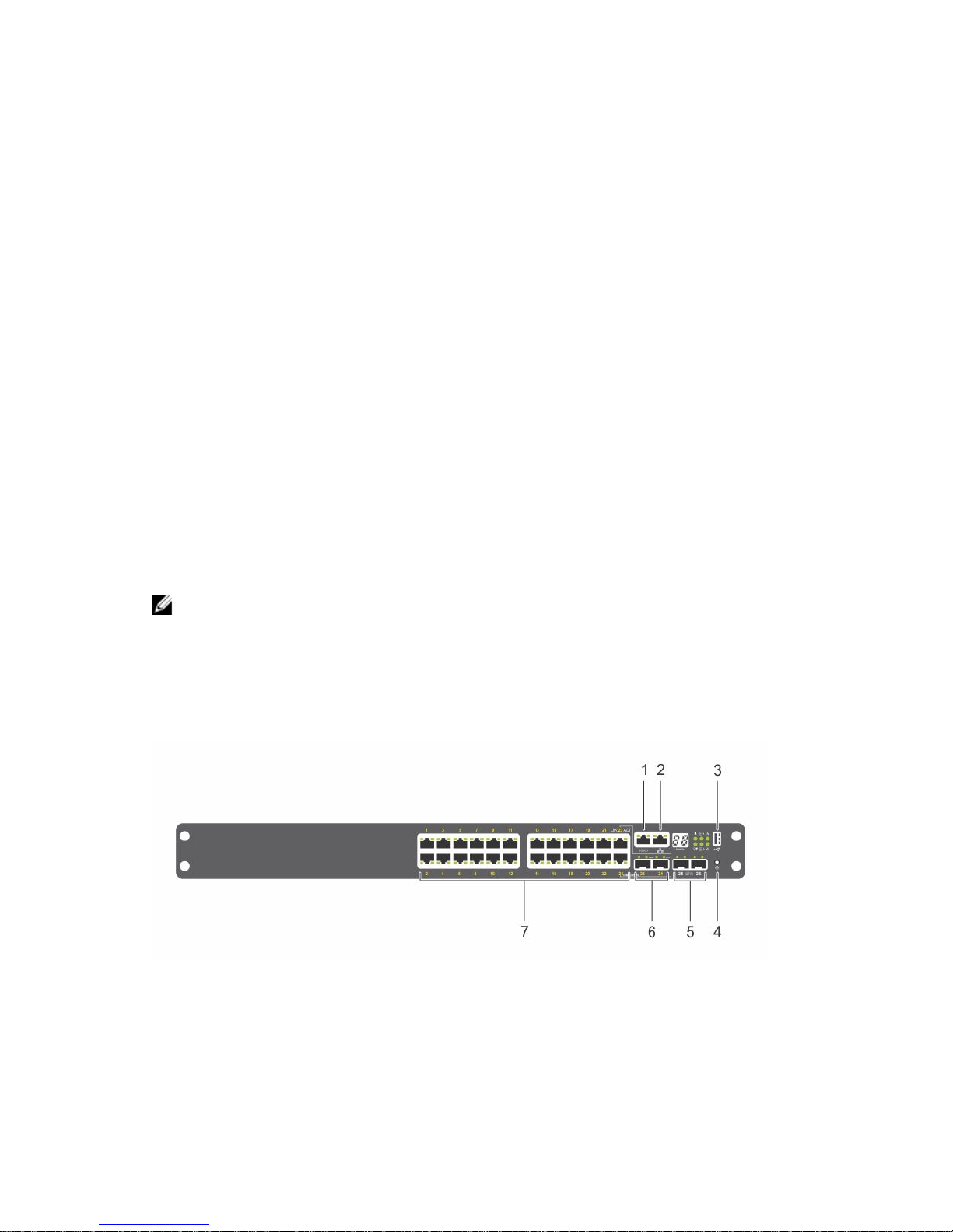
The S3124 platform input/output (I/O) side (shown in the following illustration) contains twenty-four 1G
copper switch ports. The I/O side also contains a console port, management port, serial bus port, reset
button, two 10G SFP+ ports, and two 1G SFP combo ports.
Figure 1. S3124 I/O Side View
1. Console port.
2. Management port (RJ-45 type).
3. One universal serial bus port (USB Type-A) for storage.
S3100 Series Hardware Overview
5

4. Reset button.
5. Two 10G SFP+ ports.
6. Two 1G SFP combo ports.
7. Twenty-four 1G copper switch ports.
S3124 Platform PSU Side
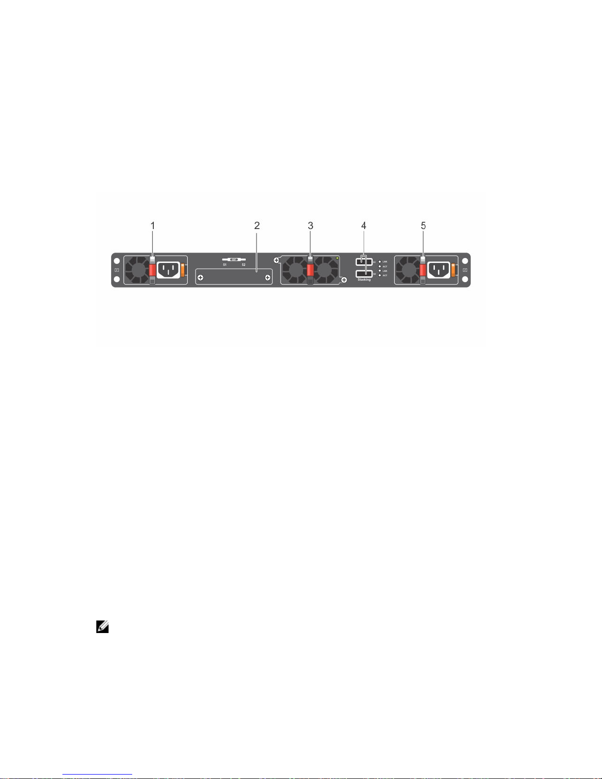
The S3124 PSU side (shown in the following illustration) includes the power supplies, fan tray, and
stacking ports.
Figure 2. S3124 PSU Side View
1. PSU 1.
2. Module slot.
3. Fan tray.
4. Mini-SAS stacking ports.
5. PSU 2.
NOTE: The S3124 platform does not support stacking with Dell Networking OS 9.8(2.0).
6
S3100 Series Hardware Overview

S3124F Platform I/O Side
The S3124F platform I/O side (shown in the following illustration) contains twenty-four 1G fiber switch
ports. The I/O side also contains a console port, management port, serial bus port, reset button, two 10G
SFP+ ports, and two 1G copper combo ports.
Figure 3. S3124F I/O Side View
1. Console port.
2. Management port (RJ-45 type).
3. One universal serial bus port (USB Type-A) for storage.
4. Reset button.
5. Two 10G SFP+ ports.
6. Two 1G copper combo ports.
7. Twenty-four 1G fiber switch ports.
S3124F Platform PSU Side
The S3124F PSU side (shown in the following illustration) includes the power supplies, fan tray, and
stacking ports.
Figure 4. S3124F PSU Side View
1. PSU 1.
S3100 Series Hardware Overview
7

2. Module slot.
3. Fan tray.
4. Mini-SAS stacking ports.
5. PSU 2.
NOTE: The S3124 platform does not support stacking with Dell Networking OS 9.8(2.0).
S3124P Platform I/O Side
The S3124P platform I/O side (shown in the following illustration) contains twenty-four 1G copper switch
ports that include PoE+ function. The I/O side also contains a console port, management port, serial bus
port, reset button, two 10G SFP+ ports, and two 1G SFP combo ports.
Figure 5. S3124P I/O Side View
1. Console port.
2. Management port (RJ-45 type).
3. One universal serial bus port (USB Type-A) for storage.
4. Reset button.
5. Two 10G SFP+ ports.
6. Two 1G SFP combo ports.
7. Twenty-four 1G copper switch ports including PoE+ function.
8
S3100 Series Hardware Overview

S3124P Platform PSU Side
The S3124P PSU side (shown in the following illustration) includes the power supplies, fan tray, and
stacking ports.
Figure 6. S3124P PSU Side View
1. PSU 1.
2. Module slot.
3. Fan tray.
4. Mini-SAS stacking ports.
5. PSU 2.
S3148P Platform I/O Side
The S3124P platform I/O side (shown in the following illustration) contains forty-eight 1G copper switch
ports that include PoE+ function. The I/O side also contains a console port, management port, serial bus
port, reset button, two 10G SFP+ ports, and two 1G SFP combo ports.
Figure 7. S3148P I/O Side View
1. Console port.
2. Management port (RJ-45 type).
3. One universal serial bus port (USB Type-A) for storage.
S3100 Series Hardware Overview
9
4. Reset button.
5. Two 10G SFP+ ports.
6. Two 1G SFP combo ports.
7. Forty-eight 1G copper switch ports including PoE+ function.
S3148P Platform PSU Side
The S3148P PSU side (shown in the following illustration) includes the power supplies, fan tray, and
stacking ports.
Figure 8. S3148P PSU Side View
1. PSU 1.
2. Module slot.
3. Fan tray.
4. Mini-SAS stacking ports.
5. PSU 2.
Reset Button
The reset button allows you to perform a hard reset on the switch. The reset button is accessed through
the pinhole on the I/O side of the chassis.
To perform a hard reset of the switch, insert the tip of a paper clip or similar tool into the pinhole. When
the switch completes the boot process after the reset, it resumes operation with the most recently saved
configuration. Any changes made to the running configuration that were not saved to the startup
configuration prior to the reset are lost.
Power Supplies
S3100 systems support two hot-swappable power supply units (PSUs) with integrated fans that provide
cooling for the system. The type of PSU differs by platform.
NOTE: Two PSUs are required for full redundancy, but the systems can operate with a single PSU.
The S3100 systems ship with one PSU. You can purchase a second PSU as a separate purchased
part.
10
S3100 Series Hardware Overview
CAUTION: To prevent electrical shock, ensure that the system is grounded properly. If you do not
ground your equipment correctly, excessive emissions may result. To ensure that the power
cables meet your local electrical requirements, use a qualified electrician.
The S3124 and S3124F platforms include the following PSU options:
• One PSU — 200 Watt.
• Two PSUs — total of 400 Watt.
• V-lock receptacle for a power cord with the V-lock feature.
The S3124P platform includes the following PSU options:
• One PSU — 715 Watt (default configuration) or 1100 Watt.
• Two PSUs — total of 1430 Watt or total of 2200 Watt.
The S3148P platform includes the following PSU options:
• One PSU — 1100 Watt.
• Two PSUs — total of 2200 Watt.
Fans
The S3100 systems come from the factory with a two-fan unit tray that is field replaceable. Additionally,
each PSU has an internal fan.
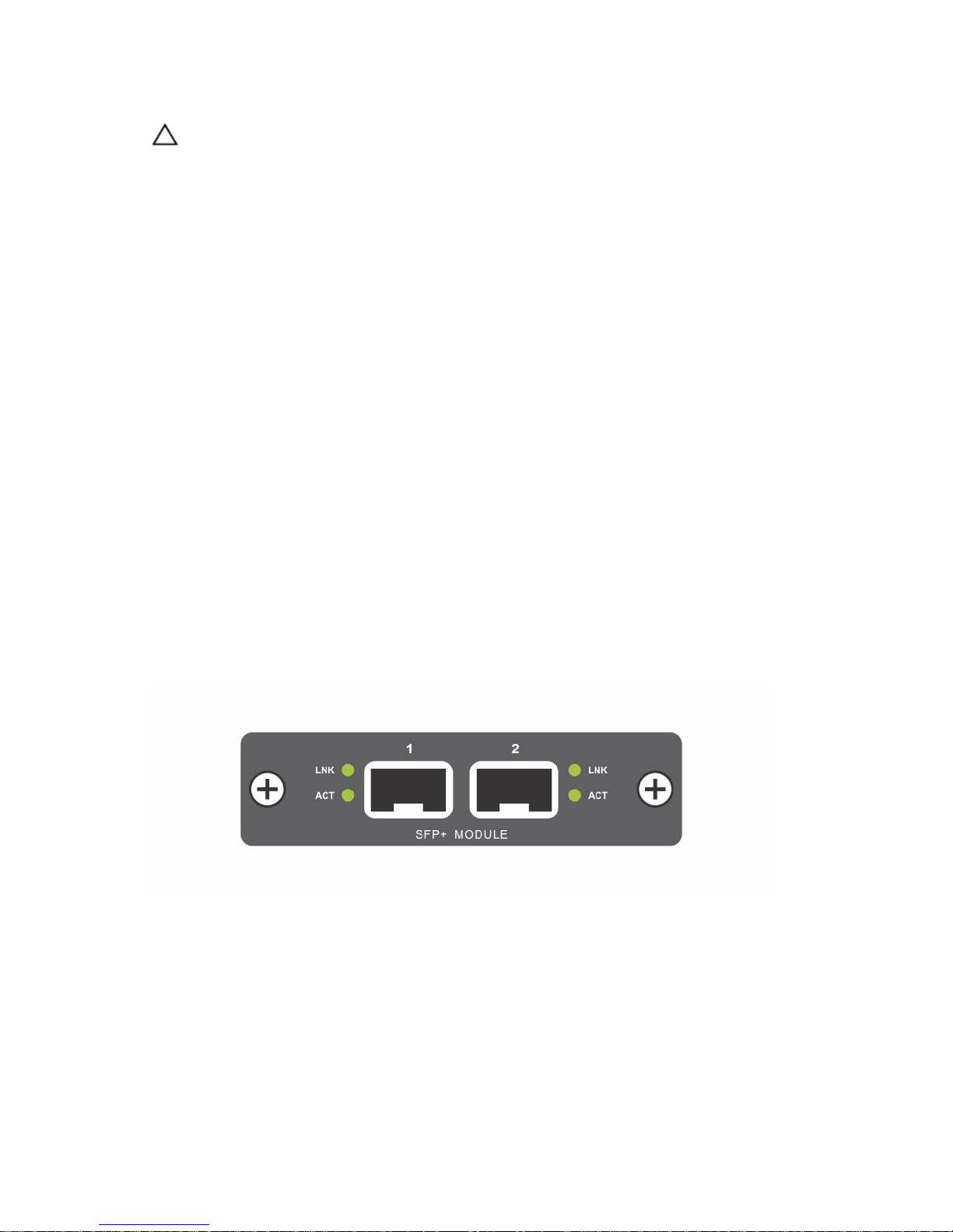
Plug-in Modules
One expansion slot is on the PSU side of the S3100 series chassis and can support either an SFP+ or
10GBase-T module.
Each plug-in module has two ports. The modules are sold separately.
Figure 9. SFP+ Module
S3100 Series Hardware Overview
11

Figure 10. 10GBase-T Module
LED Status Information
The S3100 systems include LED displays on both the I/O and PSU side of the chassis.
You can also view status information through the command line interface (CLI) show commands and
with the simple network management protocol (SNMP). For more information about these options, see
the Dell Command Line Reference Guide for the S3100 Series and the Dell Configuration Guide for the
S3100 Series.
NOTE: Within the S3100 series, the S3124P and S3148P platforms support stacking with Dell
Networking OS 9.8(2.0). The S3124 and S3124F platforms do not support stacking with Dell
Networking OS 9.8(2.0).
The S3124 I/O side (shown in the following illustration) includes LED displays for port, system, and stack
status.
Figure 11. S3124 I/O Side LEDs
12
S3100 Series Hardware Overview

1. Gigabit Ethernet (10/100/1000BASE-T) RJ-45 port LNK.
2. Gigabit Ethernet (10/100/1000BASE-T) RJ-45 port ACT.
3. Console port LNK.
4. Management port LNK.
5. Management port ACT.
6. Stack number.
7. Temperature.
8. PSU 1.
9. System Status.
10. Fan.
11. PSU 2.
12. M (Master).
13. SFP+ (10G) port ACT.
14. SFP+ (10G) port LNK.
15. Combo SFP (1G) port ACT.
16. Combo SFP (1G) port LNK.
Table 1. S3124 I/O Side LED Descriptions
Feature Detailed Description
Gigabit Ethernet
(10/100/1000BASE-T) RJ-45 port
LNK (Link speed):
• Green — link up at 1000 Mbps speed.
• Yellow — link up at 10/100 Mbps speed.
• Off — no link.
ACT (Data transmission):
• Blinking green — activity.
• Off — no activity.
Console port
LNK (Link speed):
• Off — no link.
• Solid green — link.
Management port
LNK (Link speed):
• Off — no link.
• Solid green — link on 1 G speed.
• Solid amber — link on 100 M or 10 M speeds.
ACT (Data transmission):
• Blinking green — activity.
• Off — no activity.
Stack number
• Displays the stack unit number of the switch.
• Displays 1 if switch is not part of a stack.
Temperature
• Solid green — system temperature is below threshold limit.
• Solid red — system temperature has exceeded the threshold
limit of 75°C.
S3100 Series Hardware Overview
13

Feature Detailed Description
PSU 1 and 2
• Off — power failure or no power.
• Solid green — normal operation.
• Blinking green — locator function is enabled.
System status
• Solid green — normal operation. The CLI prompt is available.
• Blinking green — boot-up in progress.
• Solid red — critical system error.
• Blinking red — noncritical system error (fan fail, power supply
fail).
Fan
• Solid green — fan is powered and running at the expected rpm.
• Solid red — fan failed.
M (Master)
• Solid green — system is in Stacking Master mode.
• Off — switch is in Slave mode.
SFP+ (10G) port
LNK (Link speed):
• Off — no link.
• Solid green — link on 10 G speed.
• Solid amber — link on 1 G speed.
ACT (Data transmission):
• Off — no link.
• Blinking green — activity.
Combo SFP (1G) port
LNK (Link speed):
• Off — no link.
• Solid green — link on 1000 Mbps speed.
• Solid amber — link on 100 Mbps speed.
ACT (Data transmission):
• Off — no link.
• Blinking green — activity.
The S3124F I/O side (shown in the following illustration) includes LED displays for port, system, and stack
status.
14
S3100 Series Hardware Overview
 Loading...