

Page 1

Dell Networking Operating System for
OpenFlow on N-Series (DNOS-OF)
User Guide v1.1b
Dell Networking Engineering (Campus)
June 2016
©2016 Dell Inc., All rights reserved. Except as stated below, no part of this document may be reproduced, distributed
or transmitted in any form or by any means, without express permission of Dell. You may distribute this document
within your company or organization only, without alteration of its contents.
THIS DOCUMENT IS PROVIDED “AS-IS”, AND WITHOUT ANY WARRANTY, EXPRESS OR IMPLIED. IMPLIED
WARRANTIES OF MERCHANTABILITY AND FITNESS FOR A PARTICULAR PURPOSE ARE SPECIFICALLY DISCLAIMED.
PRODUCT WARRANTIES APPLICABLE TO THE DELL PRODUCTS DESCRIBED IN THIS DOCUMENT MAY BE FOUND
AT: http://www.dell.com/learn/us/en/vn/terms-of-sale-commercial-and-public-sector-warranties Performance of
network reference architectures discussed in this document may vary with differing deployment conditions, network
loads, and the like. Third party products may be included in reference architectures for the convenience of the reader.
Inclusion of such third party products does not necessarily constitute Dell’s recommendation of those products.
Please consult your Dell representative for additional information.
Trademarks used in this text: Dell™, the Dell logo, Dell Boomi™, Dell Precision™ ,OptiPlex™, Latitude™, PowerEdge™,
PowerVault™, PowerConnect™, OpenManage™, EqualLogic™, Compellent™, KACE™, FlexAddress™, Force10™ and
Vostro™ are trademarks of Dell Inc. Other Dell trademarks may be used in this document. Cisco Nexus®, Cisco
MDS®, Cisco NX-0S®, and other Cisco Catalyst® are registered trademarks of Cisco System Inc. EMC VNX®, and
EMC Unisphere® are registered trademarks of EMC Corporation. Intel®, Pentium®, Xeon®, Core® and Celeron® are
registered trademarks of Intel Corporation in the U.S. and other countries. AMD®is a registered trademark and AMD
Opteron™, AMD Phenom™ and AMD Sempron™ are trademarks of Advanced Micro Devices, Inc. Microsoft®,
Windows®, Windows Server®, Internet Explorer®, MS-DOS®, Windows Vista® and Active Directory® are either
trademarks or registered trademarks of Microsoft Corporation in the United States and/or other countries. Red Hat®
and Red Hat® Enterprise Linux® are registered trademarks of Red Hat, Inc. in the United States and/or other countries.
Novell® and SUSE® are registered trademarks of Novell Inc. in the United States and other countries. Oracle® is a
registered trademark of Oracle Corporation and/or its affiliates. Citrix®, Xen®, XenServer® and XenMotion® are either
registered trademarks or trademarks of Citrix Systems, Inc. in the United States and/or other countries. VMware®,
Virtual SMP®, vMotion®, vCenter® and vSphere® are registered trademarks or trademarks of VMware, Inc. in the
United States or other countries. IBM® is a registered trademark of International Business Machines Corporation.
Broadcom® and NetXtreme® are registered trademarks of Broadcom Corporation. Qlogic is a registered trademark of
QLogic Corporation. Other trademarks and trade names may be used in this document to refer to either the entities
claiming the marks and/or names or their products and are the property of their respective owners. Dell disclaims
proprietary interest in the marks and names of others.
NOTE: A NOTE indicates important information that helps you make better use of your computer.
Page 2

CAUTION: A CAUTION indicates either potential damage to hardware or loss of data and tells you how to avoid the problem.
WARNING: A WARNING indicates a potential for property damage, personal injury, or death.
2015–03, Rev. A02
2
Page 3

Table of contents
1 Executive summary – DNOS-OF ............................................................................................................................................ 7
1.1 DNOS-OF Overview ....................................................................................................................................................... 7
1.2 About This Document .................................................................................................................................................... 7
1.3 Additional Documentation ............................................................................................................................................ 7
2 User Guide .................................................................................................................................................................................. 8
2.1 Embedded Management (CLI/GUI) ............................................................................................................................. 8
2.2 Supported Hardware ...................................................................................................................................................... 8
2.3 Limitations and Product Constraints ........................................................................................................................... 8
3 Product Features – SDN/OpenFlow and DNOS-OF ......................................................................................................... 10
3.1 Overview – What is SDN? ............................................................................................................................................ 10
3.2 Overview – What is OpenFlow? ................................................................................................................................. 10
3.3 Overview – What is DNOS-OF? .................................................................................................................................. 11
4 Product Details ......................................................................................................................................................................... 12
4.1 SDN and the OpenFlow Architecture ........................................................................................................................ 12
4.1.1 SDN/OpenFlow High Level Architectural Components ........................................................................................ 12
4.2 DNOS-OF Product Details........................................................................................................................................... 13
4.2.1 High Level Architecture................................................................................................................................................ 13
4.2.2 Indigo .............................................................................................................................................................................. 14
4.2.3 of-switch Main Application ......................................................................................................................................... 14
4.2.4 OF-DPA SDK .................................................................................................................................................................. 14
4.3 OpenFlow Multi Table Programming supported by DNOS-OF ........................................................................... 15
4.3.1 Bridging and Routing Functions ................................................................................................................................. 15
4.3.2 DNOS-OF Object Descriptions – Flow Tables and Group Tables ....................................................................... 16
4.3.2.1 Ingress Port Flow Table .................................................................................................................... 17
4.3.2.1.1 Match Criteria, Instructions, Actions/Action List/Action Set, Counters, Flow Expiry ............ 17
4.3.2.2 VLAN Flow Table .......................................................................................................................... 18
4.3.2.2.1 Match Criteria, Instructions, Actions/Action List/Action Set, Counters, Flow Expiry ........... 18
4.3.2.3 Termination MAC Flow Table ..................................................................................................... 20
4.3.2.3.1 Match Criteria, Instructions, Actions/Action List/Action Set, Counters, Flow Expiry ........... 20
4.3.2.4 Bridging Flow Table ..................................................................................................................... 22
4.3.2.4.1 Match Criteria, Instructions, Actions/Action List/Action Set, Counters, Flow Expiry ........... 22
4.3.2.5 Unicast Routing Flow Table ........................................................................................................ 24
4.3.2.5.1 Match Criteria, Instructions, Actions/Action List/Action Set, Counters, Flow Expiry ........... 24
4.3.2.6 Multicast Routing Flow Table ..................................................................................................... 26
3
Page 4

4.3.2.6.1 Match Criteria, Instructions, Actions/Action List/Action Set, Counters, Flow Expiry ........... 26
4.3.2.7 Policy ACL Flow Table ..................................................................................................................... 28
4.3.2.7.1 Match Criteria, Instructions, Actions/Action List/Action Set, Counters, Flow Expiry ........... 28
4.4 Group Table ................................................................................................................................................................... 32
4.4.1 DNOS-OF flow tables................................................................................................................................................... 33
4.4.2 DNOS-OF L2 Interface Group Entries ....................................................................................................................... 33
4.4.2.1 Naming Convention ........................................................................................................................ 34
4.4.2.2 Action Buckets.............................................................................................................................. 34
4.4.2.3 Counters ....................................................................................................................................... 34
4.4.3 DNOS-OF L2 Rewrite Group Entries ......................................................................................................................... 35
4.4.3.1 Naming Convention ........................................................................................................................ 35
4.4.3.2 Action Buckets.............................................................................................................................. 35
4.4.3.3 Counters ....................................................................................................................................... 35
4.4.4 DNOS-OF L3 Unicast Group Entries ......................................................................................................................... 36
4.4.4.1 Naming Convention .................................................................................................................... 36
4.4.4.2 Action Buckets.............................................................................................................................. 36
4.4.4.3 Counters ....................................................................................................................................... 37
4.4.5 DNOS-OF L2 Multicast Group Entries....................................................................................................................... 37
4.4.5.1 Naming Convention ........................................................................................................................ 37
4.4.5.2 Action Buckets.............................................................................................................................. 37
4.4.5.3 Counters ....................................................................................................................................... 38
4.4.6 DNOS-OF L2 Flood Group Entries............................................................................................................................. 38
4.4.6.1 Naming Convention ........................................................................................................................ 38
4.4.6.2 Action Buckets.............................................................................................................................. 39
4.4.6.3 Counters ....................................................................................................................................... 39
4.4.7 DNOS-OF L3 Interface Group Entries ....................................................................................................................... 39
4.4.7.1 Naming Convention ........................................................................................................................ 40
4.4.7.2 Action Buckets.............................................................................................................................. 40
4.4.7.3 Counters ....................................................................................................................................... 40
4.4.8 DNOS-OF L3 Multicast Group Entries ....................................................................................................................... 41
4.4.8.1 Naming Convention .................................................................................................................... 42
4.4.8.2 Naming Convention .................................................................................................................... 42
4.4.8.1 Counters ....................................................................................................................................... 42
4
Page 5

4.4.9 DNOS-OF L3 ECMP Group Entries ............................................................................................................................ 42
4.4.9.1 Naming Convention ........................................................................................................................ 43
4.4.9.2 Action Buckets.............................................................................................................................. 43
4.4.9.3 Counters ....................................................................................................................................... 43
4.4.10 Fast Failover Group Entries ..................................................................................................................................... 43
4.4.11 Meters.............................................................................................................................................................................. 43
4.4.12 Ports ............................................................................................................................................................................ 44
4.4.12.1 Physical Ports ............................................................................................................................... 44
4.4.12.2 Counters ....................................................................................................................................... 46
4.4.12.3 Reserved Ports .............................................................................................................................. 47
4.4.13 Vendor Extension Features ..................................................................................................................................... 48
4.4.13.1 Source MAC Learning .................................................................................................................. 48
4.4.13.2 Group Properties .......................................................................................................................... 48
4.5 OpenFlow Single Table Programming Supported by DNOS-OF (NEC PF6800 PFC Cluster Controller
compatibility mode) ................................................................................................................................................................ 49
4.5.1 Bridging and Routing Functions in NEC ................................................................................................................... 49
5 Installation, Configuration, Deployment ............................................................................................................................. 56
5.1 View current installed OS ............................................................................................................................................ 56
5.2 Install DNOS-OF ............................................................................................................................................................ 57
5.3 Configure Management Access ................................................................................................................................. 57
5.4 Configure Controller Communications Channel.................................................................................................... 58
5.4.1 Example Multitable (Ryu) Controller Configuration................................................................................................ 58
5.4.2 Example Singletable (NEC) Controller Configuration ............................................................................................ 61
5.5 Verifying the Switch to Controller Communications ............................................................................................. 64
5.5.1 Verfying Topology with Ryu Controller .................................................................................................................... 67
5.5.2 Verifying Topology with NEC Controller .................................................................................................................. 69
5.6 Logging ........................................................................................................................................................................... 72
5.6.1 View Logging Configuration ....................................................................................................................................... 72
5.6.1.1 show logging .................................................................................................................................... 72
5.6.1.2 show ip syslog service ..................................................................................................................... 73
5.6.2 Enable or Change Runtime Logging Levels/Components .................................................................................... 73
5.6.2.1 set logging component................................................................................................................... 73
5.6.2.2 set logging level ........................................................................................................................... 73
5.6.3 Enable or Change Default Logging Levels/Components ...................................................................................... 73
5.6.3.1 set default logging component ..................................................................................................... 73
5
Page 6

5.6.3.2 set default logging level .............................................................................................................. 74
5.6.4 Syslog Configuration .................................................................................................................................................... 74
5.7 Switch Configuration Storage..................................................................................................................................... 74
5.7.1 startup-config ................................................................................................................................................................ 74
5.7.2 running-config .............................................................................................................................................................. 75
5.7.3 backup-config ............................................................................................................................................................... 76
A Appendix - DNOS-OF CLI Command Reference .............................................................................................................. 79
A.1 Commands .....................................................................................................................................................................80
B Appendix – Setting up flows with the DNOS-OF SDN Agent, Ryu SDN Controller, and Ryu REST API ................ 137
1. Ryu 3.23.2 Installation ................................................................................................................................................ 137
2. Starting the Ryu controller with the REST API enabled ........................................................................................ 137
3. Where within the Ryu directory structure to find the REST API script .............................................................. 142
C Appendix - Example of setting up a basic Ethernet L2 Bridging topology for end to end traffic with Ryu .......... 143
C.1 System Diagram for example flow ........................................................................................................................... 143
C.2 Step 1 - Set up a VLAN flow with Ryu ...................................................................................................................... 144
C.3 Step 2 - Set up a Group Entry in Ryu ....................................................................................................................... 147
C.4 Step 3 - Set up a Bridging Flow in Ryu .................................................................................................................... 147
D Appendix - additional resources ......................................................................................................................................... 149
6
Page 7

1 Executive summary – DNOS-OF
SDN and OpenFlow is fast becoming a requirement in campus networking products due to the perceived
strategic value of SDN and the high perceived cost of proprietary legacy network gear. DNOS-OF is a campus
networking product based on existing N Series hardware and a custom firmware image.
1.1 DNOS-OF Overview
DNOS-OF is a web downloadable firmware image available for the Dell Networking N-Series hardware
that enables OpenFlow 1.3.4 support as a pure OpenFlow switch. It is intended to:
• Provide basic easy to use pure OpenFlow mode support on N-Series switches to enable SDN for Campus
networks, no hybrid mode is supported.
• Co-exist with the existing N-Series firmware images and image management, while not affecting any
existing functionality. This requires the ability to load DNOS-OF code from within the users existing
firmware, run as a pure OF switch, and revert back with no impact to the users existing firmware, including
their running configuration and switch settings.
• Leverage Broadcom’s OFDPA (OpenFlow Data Path Abstraction) SDK to provide basic OpenFlow agent
integration, along with abstracting the SOC hardware tables when presenting them as OpenFlow flow
tables.
• Network administrators are able to select the OS for the switch in the same manner they select which
firmware image they want to run today.
• Provide limited and simpler features and functionality in order to allow for delivery of a quick and low cost
solution that is easy to test out in customer lab environments.
• Provide support for the Ryu OpenFlow controller and the NEC PF6800 PFC controller cluster.
1.2 About This Document
This guide describes the product and its purpose, how to configure, monitor, and maintain DNOS-OF on
the Dell Networking N-Series switches, a reference for the DNOS-OF command-line interface (CLI) and
some basic examples showing how to set up Ryu for a single end to end Layer 2 traffic flow in DNOS-OF,
and a configuration guide for setting up Layer 2 vBridges and Layer 3 vRouters with VTN’s (virtual tenant
networks) in the NEC controller.
1.3 Additional Documentation
Documents for the Dell Networking series switches are available at dell.com/support.
7
Page 8

2 User Guide
2.1 Embedded Management (CLI/GUI)
There is a CLI provided by the DNOS-OF platform that is accessible from the serial port, telnet, and SSH.
There is currently no other management access, however a GUI is planned for release with DNOS-OF 1.1.
The CLI reference is also included in an appendix at the end of this document.
2.2 Supported Hardware
The DNOS-OF firmware is supported on the following N-Series platforms as of release 1.1:
– 1524
– 1524P
– 1548
– 1548P
– 2024
– 2024P
– 2048
– 2048P
– 3024
– 3024P
– 3048
– 3048P
– 4032
– 4032F
– 4064
– 4064F
2.3 Limitations and Product Constraints
Dell Networking N-Series switches with the DNOS-OF firmware installed are pure OpenFlow only
switches. No legacy functions are available, nor is hybrid mode
The primary user interface is CLI, however there is a GUI under development.
Only a single OpenFlow instance is supported, which includes all physical ports.
The OpenFlow 1.3.4 spec is the only initial mode of compatibility supported, there is no backwards
compatibility with prior versions of the OpenFlow spec.
DNOS-OF is only qualified with the Ryu controller and the NEC PF6800 PFC cluster controller. This is in
alignment with DNOS-9.x and their OpenFlow / SDN mode release compatibility and testing.
All OpenFlow 1.3.4 commands that are listed as “mandatory” in the spec are supported except for those
having to do with hybrid mode. Some OpenFlow 1.3.4 commands that are “optional” but that enhance the
product serviceability and value, or that are required for controller function are supported as well.
Stacking of DNOS-OF OpenFlow switches is not supported.
Basic SSH is provided in 1.1. TLS is planned for a future release,
Packet buffering is not supported.
8
Page 9

Except for minimal system internal and OpenFlow packet debugging, logging and output to the serial
console, only remote logging via SysLog is currently supported so as not to impact existing N Series code.
9
Page 10

Traditional non SDN networks vs SDN networks
3 Product Features – SDN/OpenFlow and DNOS-OF
3.1 Overview – What is SDN?
Software-Defined Networking (SDN) is a networking architecture that is dynamic, manageable, and
adaptable, making it useful for high-bandwidth applications. This architecture decouples the network
control and data plane forwarding functions, enabling the network control to become directly
programmable and the underlying infrastructure to be abstracted for applications and network services.
The OpenFlow™ protocol is a foundational element for building SDN solutions.
Some attributes of SDN architecture are:
Directly programmable: Network control is directly programmable because it is decoupled from
forwarding functions.
Agile: Abstracting control from forwarding lets administrators dynamically adjust network-wide traffic
flow to meet changing needs.
Centrally managed: Network intelligence is (logically) centralized in software-based SDN controllers
that maintain a global view of the network, which appears to applications and policy engines as a single,
logical switch.
Programmatically configured: SDN lets network managers configure, manage, secure, and optimize
network resources very quickly via dynamic, automated SDN programs, which they can write themselves
because the programs do not depend on proprietary software.
Open standards-based and vendor-neutral: When implemented through open standards, SDN
simplifies network design and operation because instructions are provided by SDN controllers instead of
multiple, vendor-specific devices and protocols.
3.2 Overview – What is OpenFlow?
The OpenFlow protocol is one instance of an SDN architecture, based on a set of specifications
maintained by the Open Networking Forum (ONF). At the core of the specifications is a definition of an
abstract packet processing machine, called a switch. The switch processes packets using a combination of
packet contents and switch configuration state. A protocol is defined for manipulating the switch's
configuration state as well as receiving certain switch events. Finally, a controller is an element that speaks
the protocol to manage the configuration state of many switches and respond to events.
More Information on the overview and genesis, current state of protocol:
https://www.opennetworking.org/images/stories/downloads/sdn-resources/white-papers/wp-sdnnewnorm.pdf
OpenFlow from Flowgrammable website: http://flowgrammable.org/
OpenFlow from Open Networking Spec website:
https://www.opennetworking.org/sdn-resources/openflow
10
Page 11

3.3 Overview – What is DNOS-OF?
As a product line, the Dell Networking Operating System – for OpenFlow, DNOS-OF is a firmware bundle
that allows a traditional N series switch to be used as a pure OpenFlow switch. DNOS-OF is designed to
1. Deliver a pure OpenFlow switch for the N series
2. Enable SDN in campus networks
3. Interoperate with any controller supporting OpenFlow 1.3.4 and multiple table support, as well
as with the NEC PF6800 PFC cluster controller.
DNOS-OF leverages the BigSwitch Networks open source Indigo agent (Indigo) and Broadcom’s
OpenFlow Data Plane Abstraction (OF-DPA) packages to provide OpenFlow support.
The DNOS-OF based abstract switch is a specialization of the OpenFlow 1.3.4 OFLS (OpenFlow logical
switch).
The DNOS-OF abstract switch objects can be thought of as programming points for the Ethernet
switching hardware. These include flow tables with action sets, group table entries, physical ports, and
queues. The DNOS-OF adaptation layer provides support for OpenFlow specific state, for example,
statistics counters. It also maps OpenFlow objects to hardware and manages hardware resources.
Supporting OpenFlow in switch hardware involves some tradeoffs. As has been noted elsewhere, the
generality promised by OpenFlow can come at a cost of latency, as well as cost and power inefficiencies.
In addition, to effectively use this generality a specific multi-table pipeline first needs to be designed and
configured. The DNOS-OF Abstract Switch may be viewed as coming preconfigured and optimized to
support single pass, full bandwidth packet processing performance that makes efficient use of the
hardware and available table memory resources, trading off unrestricted generality in favor of latency,
performance, and cost, while enabling a logically centralized control plane with programming flexibility.
The DNOS-OF Abstract Switch includes functionality to support bridging and routing functionality on the
switch chip, among other functions, by the use of flow descriptors. Flows represent groups of data plane
traffic that match the same flow description lasting for varying durations. The flow descriptors expose the
proper functionality in the switching hardware control the data path of the flows. Future versions of
DNOS-OF are expected to support additional features and packet flow use cases.
DNOS-OF implements a basic SDK based switch OS, with the primary functionality being an SDN agent, a
CLI and platform support for the various N-Series hardware components.
11
Page 12
OpenFlow Controller
User applic ation
REST
API
OpenFlow Agent
OpenFlow 1.3.4 protocol
TCP or TLS
OpenFlow Logical Switch Op enFlow Logical Switch
OpenFlow Agent
OpenFlow 1 .3.4 protocol
TCP or TLS
4 Product Details
4.1 SDN and the OpenFlow Architecture
4.1.1 SDN/OpenFlow High Level Architectural Components
At the core of the OpenFlow specifications is the definition of an abstract packet processing machine,
called a switch. The switch processes packets using a combination of packet contents and switch
configuration state. A protocol is defined for manipulating the switch's configuration state as well as
receiving certain switch events. Finally, a controller is an element that speaks the OpenFlow protocol
down to the switch based agent in order to manage the configuration state of many switches and respond
to switch events.
Controller Topology
The controllers provide flow programming instructions to agents running in the switches for setting up
switch functions and tables that are normally programmed to run on the legacy firmware on the switch
itself, such as VLAN’s, ACL entries, routing and bridging.
12
Page 13
4.2 DNOS-OF Product Details
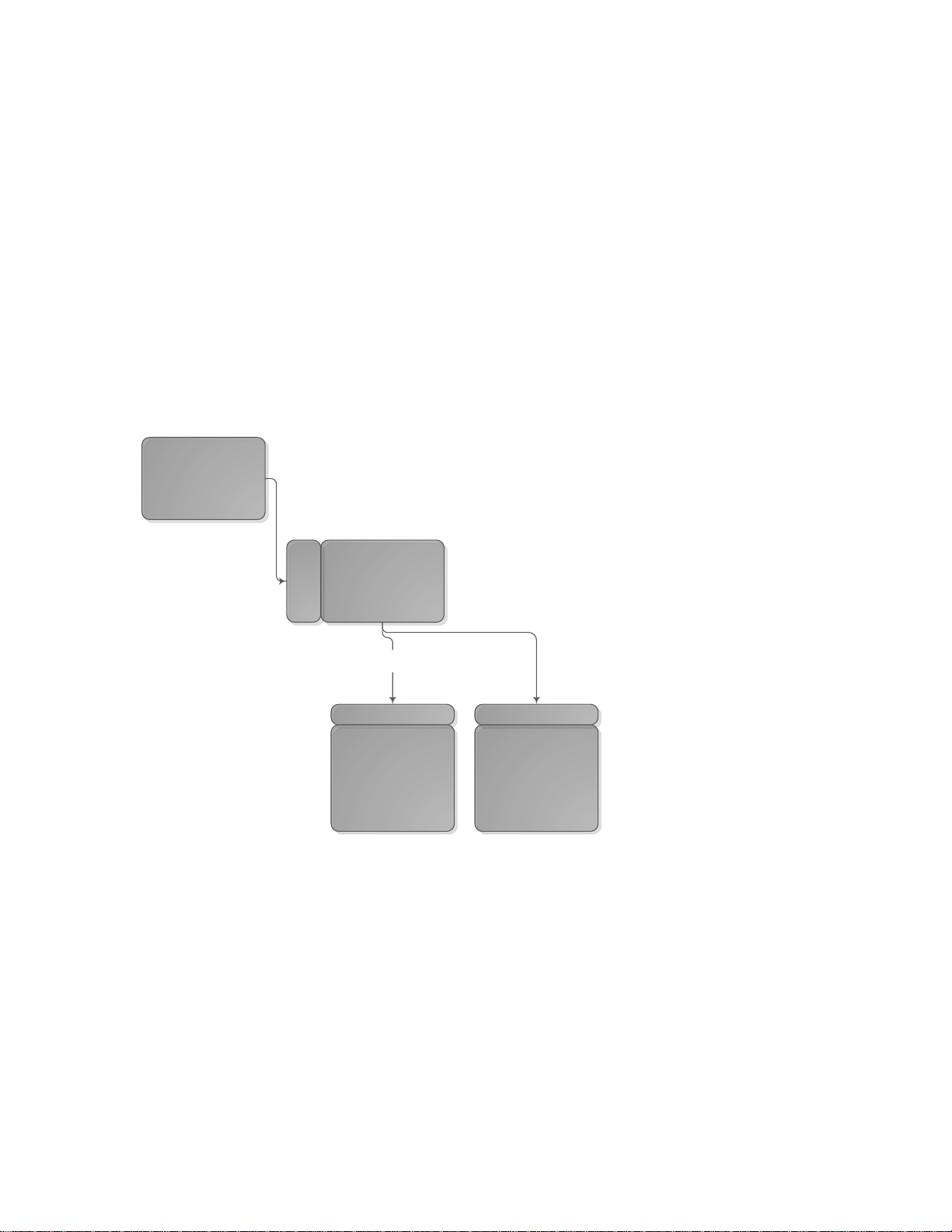
4.2.1 High Level Architecture
The network OS portion of DNOS-OF consists of minified Debian Linux kernel with a BusyBox distribution
for the main underlying core of the platform operating environment. There is some additional kernel
framework consisting of the kernel mode interface BDE drivers provided by the switch SDK.
There are also user mode drivers for all of the target platform hardware, which together makes up the Board
Support Package (BSP). There is also SDN agent functionality that handles the northbound interface to the
SDN controller. There is also functionality that implements, translates and encapsulates the SDN OpenFlow
1.3.4 protocol capability into instructions specific to the switch ASIC (the OF-DPA layer), as well as
functionality that controls the interface between the open source agent and the switch application. This
includes a CLI provided by the underlying platform interface.
The DNOS-OF 1.0 firmware was initially targeted for the N3024 and N3048 N-series family of campus
Ethernet switches from Dell and later added the PoE versions, N3024P and N3048P. DNOS-OF 1.1 added
support for the remaining N Series platforms, N1524, N1524P, N1548, N1548P, N2024, N2024P, N2048,
N2048P, N4032, N4032F, N4064, and N4064F.
Below are the primary components that make up the DNOS-OF firmware architecture in release 1.1.
Note that the OpenFlow controllers shown in this diagram are the ones officially supported by DNOS-OF
1.1, but any controller that is OpenFlow 1.3.4 compliant should work with DNOS-OF. This is mainly
dependent on the ability of the specific controller software to work with 1) OpenFlow 1.3.4, and 2) some
knowledge and support for the limitations of the hardware SOC based flow tables.
13
Page 14
4.2.2 Indigo
Indigo is an open source Big Switch Networks provided north bound OpenFlow API layer which has been
tied into the OF-DPA libraries and consequently into the switch application. It handles communications
from the OpenFlow controller to the OpenFlow agent in the DNOS-OF switch.
4.2.3 of-switch Main Application
The SDN agent providing a northbound interface to the SDN controller, the CLI, the board support
package providing platform monitoring, and the overall initiation and control of the switch applications
and various tasks takes place in the switch application.
The CLI is provided by the underlying DNOS-OF platform layer, and is currently accessible through the
serial console as well as telnet and SSH. Support for a REST API based GUI, SNMP MIB’s, and various other
management approaches are planned for a later release.
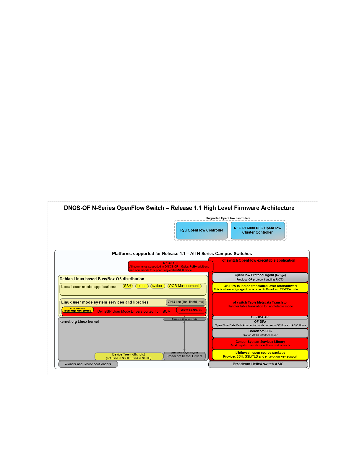
4.2.4 OF-DPA SDK
The OpenFlow Data Plane Abstraction SDK translates general OpenFlow protocol commands received and
processed by the Indigo OpenFlow agent on an abstract or virtual switch into specific rules and tables as
implemented on a Broadcom SOC product in order to establish flow directives on the hardware.
Here is a high level diagram of what is provided by OF-DPA.
14
Page 15
4.3 OpenFlow Multi Table Programming supported by DNOS-OF
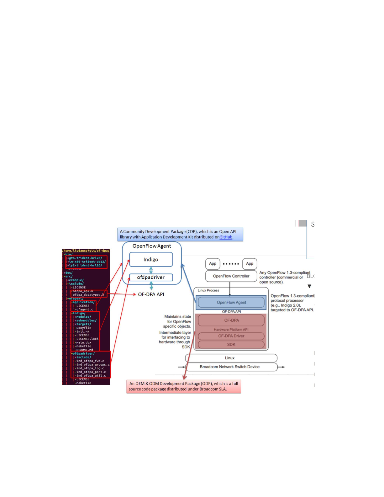
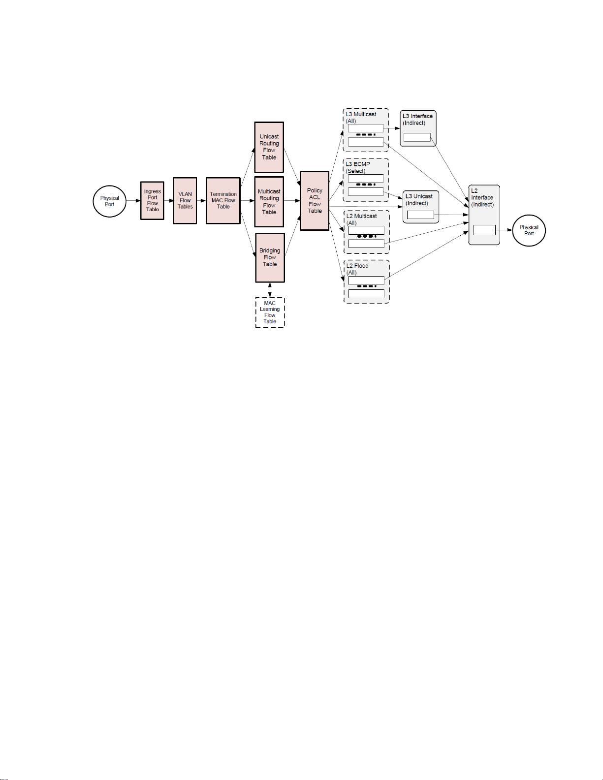
4.3.1 Bridging and Routing Functions
Figure 2. Abstract switch Objects Used for Bridging and Routing
The DNOS-OF Abstract Switch objects that can be programmed for bridging and routing in multi table
mode are shown in Figure 2.
Multi table mode exposes the tables highlighted and shown above to support direct flow table programming
access to controllers that can address multiple flow tables. The following sections describe the interface
provided by the DNOS-OF switch to the OpenFlow controller for the internal switch tables. The key OpenFlow
instruction required for multi table support is the “goto table” instruction, allowing the user to control the
data plane pipelining through the DNOS-OF switch.
Packets enter and exit the pipeline on physical ports local to the switch. The Ingress Port Flow Table (table 0) is
always the first table to process a packet. Flow entries in this table can distinguish traffic from different types
of input ports by matching associated Tunnel Id metadata. Normal bridging and routing packets from physical
ports have a Tunnel Id value of 0. To simplify programming, this table provides a default rule that passes
through packets with Tunnel Id 0 that do not match any higher priority rules. Logical ports are not supported
in DNOS-OF, so the Tunnel Id will always be 0.
All packets in the Bridging and Routing flow must have a VLAN. The VLAN Flow Table can do VLAN filtering
for tagged packets and VLAN assignment for untagged packets. If the packet has more than one VLAN tag,
the outermost VLAN Id is the one used for forwarding.
The Termination MAC Flow Table matches destination MAC addresses to determine whether to bridge or
route the packet and, if routing, whether it is unicast or multicast. MAC learning is supported using a “virtual”
flow table that is logically synchronized with the Bridging Flow Table.
When MAC learning is enabled, DNOS-OF does a lookup in the Bridging Flow Table using the source MAC,
outermost VLAN Id, and IN_PORT. A miss is reported to the controller using a Packet In message. Logically this
occurs before the Termination MAC Flow Table lookup. The MAC Learning Flow Table cannot be directly read
15
Page 16

or written by the controller. The MAC Learning Flow Table has a “virtual” table number which is reported to
the Controller in a table miss Packet-In message. It does not appear as part of the pipeline since its table
number assignment would violate the OpenFlow requirement for packets to traverse tables in monotonically
increasing order.
The ACL Policy Flow Table can perform multi-field wildcard matches, analogous to the function of an ACL in a
conventional switch.
DNOS-OF makes extensive use of OpenFlow Group entries, and most forwarding and packet edit actions are
applied based on OpenFlow group entry buckets. Groups support capabilities that are awkward or inefficient
to program in OpenFlow 1.0, such as multi-path and multicast forwarding, while taking advantage of
functionality built into the hardware.
4.3.2 DNOS-OF Object Descriptions – Flow Tables and Group Tables
DNOS-OF presents the application writer with a set of objects that can be programmed using OpenFlow 1.3.4.
The programmable objects include flow tables and group table entries.
This section provides programming descriptions for these objects. For details consult the DNOS-OF TTP (Table
Type Patterns) supplied with the firmware.
Flow tables have specific attributes, including entry types (rules) that have specific match fields, actions, and
instructions. Flow entries can have “Goto-Table” instructions that determine the next table to process the
packet. In other words, the flow entry programming determines the order in which packets traverse tables and
accumulate actions in an action set. Actions in the action set are applied prior to the packet being forwarded
when there is no next table specified. Specific forwarding actions, including egress packet edits, are for the
most part included within the action sets of the group entries. DNOS-OF uses specific types of group entries
to support different packet flow scenarios. Apply-actions instructions and action lists are also used for some
VLAN tag packet editing, and to send packets to the controller.
In the general OpenFlow case packets pass from flow table to flow table and can be arbitrarily modified
between tables. To take advantage of this generality each table stage would need to include a packet parser.
In DNOS-OF this kind of packet flow is conceptual - packets are parsed early in the pipeline and header fields
are extracted. After that it is only these fields that are passed between tables and used for matching or
modification by “apply actions” instructions. It is not expected that this distinction will matter to applications.
The next section describes the DNOS-OF flow tables in terms of their supported match fields, flow entry rule
types, instructions, actions, expiration provisions, and statistics counters. Default miss actions are also
specified for each table as applicable. Group table entry types and action set constraints are then described.
Ingress packets always have an associated Tunnel Id metadata value. For packets from physical ports this
value is always zero. Only Physical ports are supported in DNOS-OF, so no Tunnel Id values other than 0
are allowed.
NOTE: The software has other undocumented tables and groups implemented, but only the features
described here to support bridging and routing are described here. For complete table descriptions and
flow table programming capability, please consult the OF-DPA documentation.
16
Page 17

Type
Description
Normal Ethernet
Frames
Matches packets from local physical ports, identified by zero Tunnel Id. Normal
Ethernet rules have Goto-Table instructions that specify the VLAN Flow Table.
Field
Bits
Maskable
Optional
Description
IN_PORT
32
No
Yes
Ingress port. Depending on rule may be omitted to match any
IN_PORT.
Name
Argument
Description
Goto-Table
Table
Next table. For this release, must be the VLAN
Flow Table.
Apply-Actions
Action list
Can contain at most one instance of each of
the actions listed in Table 3.1
Name
Argument
Description
Set-Field
VRF
VRF for L3 lookups. Only applicable to Normal Ethernet Frame rules.
Optional.
Name
Type
Description
Active Entries,
Table
Reference count of number of active entries in the table
Duration
Per-entry
Seconds since this flow entry was installed
4.3.2.1 Ingress Port Flow Table
The Ingress Port Flow Table is the first table in the pipeline and, by convention, is numbered zero. OpenFlow
uses a 32 bit value for ifNums. In this version of DNOS-OF, the high order 16 bits are zero for physical ports
since no other port types are supported in 1.0.
The Ingress Port Flow Table presents what is essentially a de-multiplexing logic function as an OpenFlow table
that can be programmed from the controller. By default, packets from physical ports with null (zero) Tunnel Id
metadata go to the VLAN Flow Table. Entries in this table must admit ingress packets by matching the ingress
ifNum exactly, by matching Tunnel Id, or by some combination.
Note: DNOS-OF may prevent certain types of rules from being added to other tables unless there is
appropriate flow entry in the Ingress Port Flow Table.
The default on miss is for packets from physical ports to go to the VLAN Flow Table. There is no default rule
for data center overlay tunnel packets from logical ports, which are dropped on miss.
4.3.2.1.1 Match Criteria, Instructions, Actions/Action List/Action Set, Counters, Flow Expiry
The Ingress Port Flow Table supports the flow entry types listed in Table 1. This table would typically have one
rule enabling ingress packets from each port type. However, since in this release, only the physical port type
is supported, only one rule is enabled.
Table 1: Ingress Port Flow Table Entry Types
Table 2: Ingress Port Flow table Match Fields
Table 3: Ingress Port Flow Table Instructions
The Ingress Port Flow Table supports the single Goto-Table instruction listed in Table 3.
The Ingress Port Flow Table actions can optionally set the packet VRF using an action list.
Table 4: Ingress Port Flow Table Action List
Table 5: Ingress Port Flow Table Counters
17
Page 18

Type
Description
VLAN Filtering
Exact match on IN_PORT and VLAN_VID parsed from the packet. For tagged packets
with a VLAN tag containing a VLAN_VID greater than zero. Cannot be masked.
VLAN_VID cannot be used in a Port VLAN Assignment rule for untagged packets. The
only instruction is Goto-Table and must specify the Termination MAC Flow Table.
Tagged packets that do not match any rule are treated as VLAN_VIDs that are not
allowed on the port and are dropped. Can optionally assign a VRF for routed packets.
Untagged Packet
Port VLAN
Assignment
Exact match on IN_PORT and VLAN id == 0 (lower 12 bits of match field) value using
a mask value of 0x0fff (masks off OFPVID_PRESENT). Action set must assign a
VLAN_VID. The VLAN_VID value cannot be used in a VLAN Filtering rule. If the packet
does not have a VLAN tag, one will be pushed if necessary at packet egress. Rule
must have a Goto-Table instruction specifying the Termination MAC Flow Table.
Untagged packets are dropped if there is no port VLAN assignment rule. Can
optionally assign a VRF for routed packets.
Allow All VLANs
Wildcard VLAN match for a specific IN_PORT. Essentially turns off VLAN filtering
and/or assignment for a physical port. Must be lower priority than any overlapping
translation, filtering, MPLS, or VLAN assignment rule. Untagged packets that match
this rule will be assigned an illegal VLAN and may be subsequently dropped. Should
also define an L2 Unfiltered Interface group entry for the port.
VLAN Translate,
Single Tag, or
Single Tag to
Double Tag
Used to either modify the VLAN id on a single tagged packet, or to optionally modify
the VLAN id and then push another tag onto a single tagged packet. Can also
optionally assign a VRF for routed packets. By OpenFlow convention, the outermost
VLAN tag is matched independent of TPID.
4.3.2.2 VLAN Flow Table
The VLAN Flow Table is used for IEEE 801.Q VLAN assignment and filtering to specify how VLANs are to be
handled on a particular port. All packets must have an associated VLAN id in order to be processed by
subsequent tables. Packets that do not match any entry in the VLAN table are filtered, that is, dropped by
default. Note that IEEE defined BPDUs are always received untagged.
The VLAN Flow Table can optionally assign a nonzero VRF value to the packet based on the VLAN. OF-DPA
defines VRF as a new pipeline metadata field. The VRF defaults to zero if not set.
4.3.2.2.1 Match Criteria, Instructions, Actions/Action List/Action Set, Counters, Flow Expiry
The VLAN Flow Table supports the Flow Entry Types listed in Table 10. Flow entries are differentiated based
on IN_PORT, whether or not the packet was tagged, and the VLAN id in the tag.
OpenFlow has traditionally used a 16-bit field for VLAN id. Since only the low order 12 bits are needed to
express a VLAN id, OpenFlow has defined special values to indicate tagged and untagged packets. In
particular, the VLAN id 0x0000 (OFPVID_NONE, defined in the OpenFlow specification) is used to represent an
untagged packet, and 0x1000 (OFPVID_PRESENT) for a priority tagged packet. All tagged packets are
represented by VLAN id values between 0x1001 and 0x1FFE24 (OFPVID_PRESENT | VLAN id value). This
convention must be followed in programming rules from the controller. For further explanation consult the
OpenFlow 1.3.4 specification.
Note: DNOS-OF does not support matching packets just on whether or not they have a VLAN tag as
described in Table 13 of OpenFlow 1.3.4.
Note: At most two tags are supported. Entries in the OF-DPA VLAN Flow table are mutually exclusive. Any
explicit rule priority assignments are ignored.
Table 6: VLAN Flow Table Flow Entry Types
18
Page 19
Name
Argument
Description
Apply-Actions
Action List
The VLAN Flow Table supports the actions specified in Table 13.
Goto-Table
Table
For VLAN filtering or Port VLAN assignment the next table should
be the Termination MAC Flow Table.
Name
Argument
Description
Set
Field
VLAN_VID, must be
between 1 and 4094.
Sets the VLAN id on the outermost tag. If the packet is untagged
then one is pushed with the specified VLAN id and priority zero.
Set
Field
VRF
Optionally sets the VRF pipeline field. VRF must be the same in all
rules for the same VLAN.
Push
VLAN
TPID
Used in translating single to double tag. TPID must be 0x8100
(inner VLAN tag) or 0x88a8 (outer VLAN tag).
Note: The untagged packet rule applies to both untagged packets, which match VLAN_VID = 0x1000, and
IEEE 802.1P priority tagged packets, which match VLAN_VID = 0x0000. However the VLAN-PCP match field will
be set from the value in a priority VLAN tag rather than default to zero in the case of a packet without a VLAN
tag.
Note: A VLAN Flow Table rule cannot specify an IN_PORT and VLAN_VID combination that is used in a VXLAN
Access Logical Port configuration. Conversely, it must include a rule to permit an IN_PORT and VLAN_VID
combination used in a VXLAN Tunnel Next H
Table 8. VLAN Flow Table Instructions
The VLAN table uses Apply Actions for port VLAN tagging and assignment. The action list can have at most
one of each action type.
Table 9: VLAN Flow Table Action List
Note: The untagged packet action is the same as in OpenFlow 1.0. The implicit addition of a tag to an
untagged packet is tolerated but not condoned in OpenFlow 1.3.4.
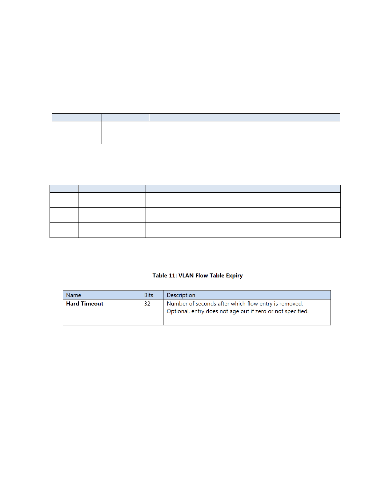
Only hard interval time-out ageing per entry is supported, as indicated in Table 9.
19
Page 20
\Field
Bits
Maskable
Optional
Description
IN_PORT
32
No
Yes
Physical (local) input port.
ETH_TYPE
16
No
No
Prerequisite for IPv4 (0x0800) or IPv6 (0x86dd).
ETH_DST
48
No
No
Ethernet destination MAC. Prefix maskable for only
the specific multicast IP flow entries in Table 28.
Can only be field masked for unicast destination
MACs.
VLAN_VID
16
Yes
Yes
Matches against the Outer VLAN id. Must be either
omitted or exact.
IPV4_DST
32
\Yes
Yes
Can only be used with 224/8 address and
224.0.0.0 mask values, otherwise must be omitted.
Prerequisite ETH_TYPE must be 0x0800.
IPv6_DST
128
Yes
Yes
Can only be used with FF00::/8 address and
FF00:0:0:0:0:0:0:0 mask values, otherwise must
be omitted. Prerequisite ETH_TYPE must be
0x86dd.
4.3.2.3 Termination MAC Flow Table
The Termination MAC Flow Table determines whether to do bridging or routing on a packet. It identifies
destination MAC, VLAN, and Ethertype for routed packets. Routed packet rule types use a goto instruction to
indicate that the next table is one of the routing tables. The default on a miss is to go to the Bridging Flow
Table.
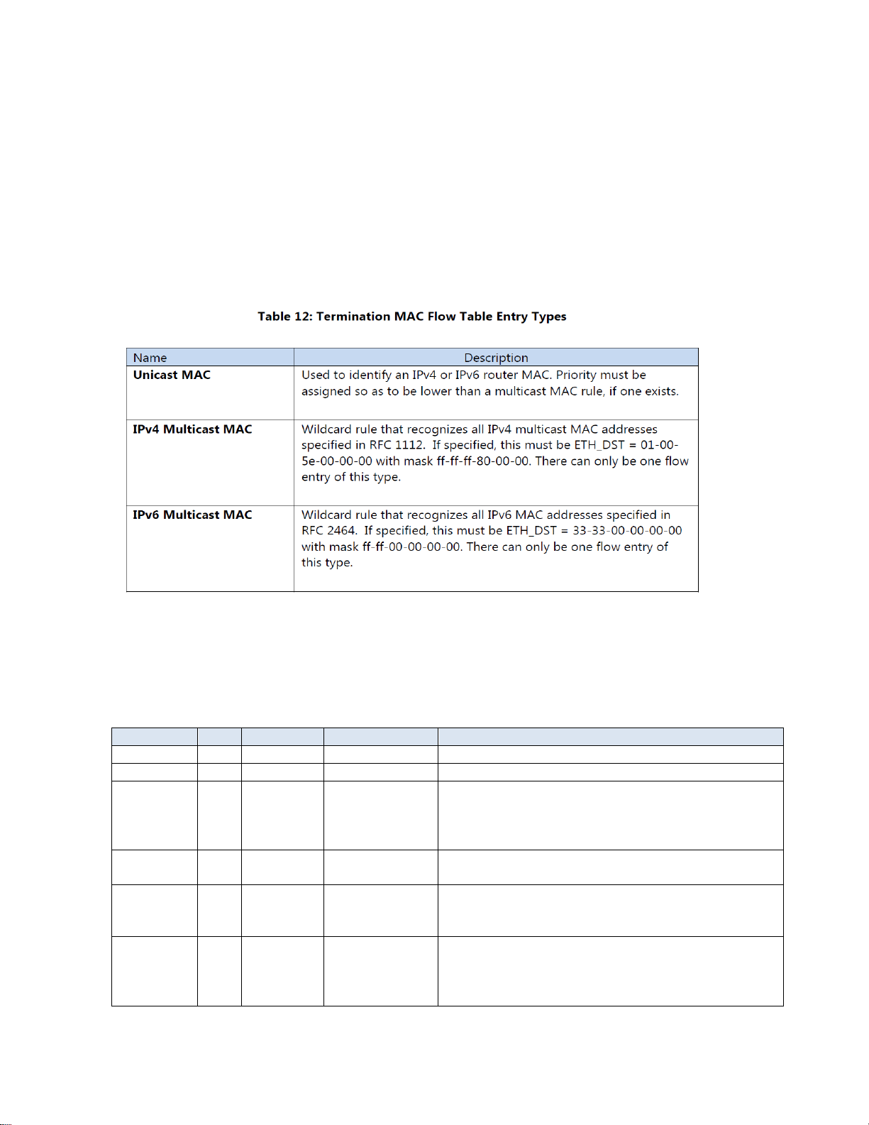
4.3.2.3.1 Match Criteria, Instructions, Actions/Action List/Action Set, Counters, Flow Expiry
The Termination MAC Flow Table implements the flow entry types listed in Table 12.
The Termination MAC Flow Table match fields are listed in Table 13. Strict rule priority must be assigned by the
controller so that every flow entry has a unique priority.
Table 13: Termination MAC Flow Table Match Fields
20
Page 21
Name
Argumen
t
Description
Goto-Table
T
a
b
l
e
Unicast MAC rules with multicast IPV4_DST or IPV6-DST should specify
the Multicast Routing Flow Table, otherwise they can only specify the
Unicast Routing Flow Table. Multicast MAC rules can only specify the
Multicast Routing Flow Table. The packet is dropped if the rule matches
and there is no Goto-Table instruction.
Apply
Actions Ac
t
i
o
n
L
i
s
t
Optional. If supplied can only contain one action, output a copy to
CONTROLLER.
The Termination MAC Flow Table can have the instructions shown in Table 14.
21
Page 22

Type
Description
Unicast
VLAN
Bridging
Matches switched unicast Ethernet frames by VLAN id and MAC_DST. MAC_DST must be
unicast and cannot be masked. VLAN id must be present and nonzero. Tunnel id must be
masked or omitted.
Multicast
VLAN
Bridging
Matches switched multicast Ethernet frames by VLAN id and MAC_DST. MAC_DST must
be multicast and cannot be masked. VLAN id must be present and nonzero. Tunnel id
must be masked or omitted.
DLF VLAN
Bridging
Matches switched Ethernet frames by VLAN id only. MAC_DST must be field masked and
match any destination. Must have lower relative priority than any unicast or multicast
flow entries that specify this VLAN. VLAN id must be present and nonzero. Tunnel id
must be masked or omitted.
Field
Bits
Maskable
Optional
Description
ETH_DST
48
Yes
Yes
Ethernet destination
MAC, allowed values
depend on flow entry
type. Exact match only
(mask must be all 1’s if
supplied).
VLAN_VID
16
Yes
Yes
VLAN id, allowed
values depend on flow
entry type. Exact
match only (mask
must be all 1’s if
supplied).
4.3.2.4 Bridging Flow Table
The Bridging Flow Table supports Ethernet packet switching for potentially large numbers of flow entries
using the hardware L2 tables. The default on a miss is to go to the Policy ACL Flow Table.
Note: The Policy ACL Flow Table is preferred for matching BPDUs.
The Bridging Flow Table forwards based on VLAN (normal switched packets) using the flow entry types in
Table 17.
Table 17: Bridging Flow Table Flow Entry Types
Note: Exact match rules must be given higher priority assignments than any wildcard rules. In any event,
exact match rules are evaluated before any wildcard rules.
4.3.2.4.1 Match Criteria, Instructions, Actions/Action List/Action Set, Counters, Flow Expiry
Match fields for flow entry types are described in the following tables.
Table 18. Bridging Flow Table Match Fields
Default next table if no match is the ACL Policy Flow Table.
22
Page 23
Type
Argument
Description
Unicast VLAN
Bridging
Group ID
Must be a DNOS_OF L2 Interface group entry for the
forwarding VLAN.
Multicast VLAN
Bridging
Group ID
Must be a DNOS_OF L2 Multicast group entry for the
forwarding VLAN.
DLF VLAN Bridging
Group ID
Must be a DNOS_OF L2 Flood group entry for the forwarding
VLAN.
The Bridging Flow Table supports the actions in Table 20 by flow entry type. The DNOS-OF API validates
consistency of flow entry type and DNOS-OF group entry type references.
Table 20: Bridging Flow Table Actions by Flow Entry Type
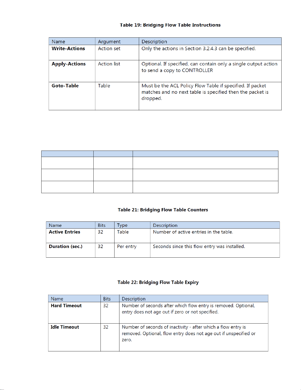
The Bridging Flow Table counters are listed in Table 21.
Bridging Flow Table expiry provisions are shown in Table 22.
23
Page 24

Type
Table
Prerequisite(s)
Description
IPv4 Unicast
Table 40
Ethertype=0x0800
Matches routed unicast IPv4
packets. The Goto-Table
instruction specifies the Policy
ACL Table.
IPv6 Unicast
Table 41
Ethertype=0x86dd
Matches routed unicast IPv6
packets. The Goto-Table
instruction specifies the Policy
ACL Table.
Field
Bits
Maskable
Optional
Description
ETH_TYPE
16
No
No
Must be 0x0800
VRF
16
No
Yes
If omitted or zero indicates the default routing table.
IPv4 DST
12
Yes
No
Must be a unicast IPv4 address. Prefix maskable only,
mask used for LPM forwarding.
Field
Bits
Maskable
Optional
Description
ETH_TYPE
16
No
No
Must be 0x86dd
VRF
16
No
Yes
If omitted or zero indicates the default routing table.
IPV6_DST
128
Yes
No
Must be a unicast IPv6 address. Prefix maskable only,
used for LPM forwarding.
Name
Argument
Description
Write-Actions
Action set
Only the actions in Table 27 can be specified.
Clear-Actions
-
Used to delete any forwarding decision so that the packet will be dropped.
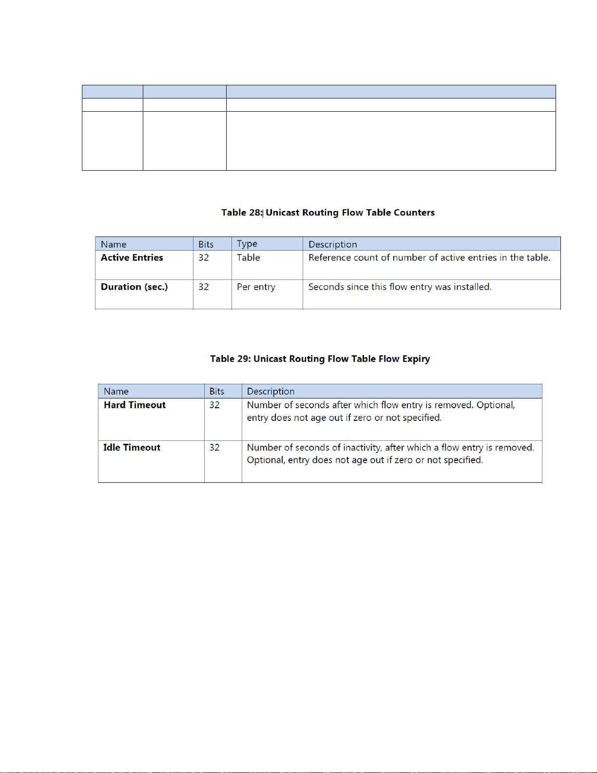
4.3.2.5 Unicast Routing Flow Table
The Unicast Routing Flow Table supports routing for potentially large numbers of IPv4 and IPv6 flow entries
using the hardware L3 tables.
The Unicast Routing Flow Table is a single table organized as two mutually exclusive logical subtables by IP
protocol, and supports flow entry types listed in Table 23. One table number is used for both logical tables.
Table 23. Unicast Routing Flow Table Entry Types
4.3.2.5.1 Match Criteria, Instructions, Actions/Action List/Action Set, Counters, Flow Expiry
Table 24. Unicast Routing Flow Table IPv4 Header Match Fields
Table 25. Unicast Routing Flow Table IPv6 Header Match Fields
Note: Exact match rules must be given higher priority assignments than any LPM prefix match rules. In any
event, the hardware evaluates exact match rules before any wildcard rules.
Note: Rules that specify a nonzero VRF must have higher relative priority than other overlapping rules. The
wildcard rules are effectively “global” or “default” in that they are matched last, that is, if no specific VRF
rule matches the packet. If the packet VRF is zero it can only match one of the wildcard rules.
Default next table on a miss is the ACL Policy Flow Table.
Table 26: Unicast Routing Flow Table Instructions
24
Page 25
Name
Argument
Description
Group
Group ID
Must be a DNOS-OF L3 Unicast Group Entry.
Decrement
TTL and
do MTU
check
-
MTU check is a vendor extension. An invalid TTL (zero before or after
decrement) is always dropped and a copy sent to the CPU for forwarding
to the CONTROLLER. Similarly, a packet that exceeds the MTU is
dropped and a copy sent to the CONTROLLER. Required.
Other instruction types, specifically Apply Actions, are not supported.
Table 27: Unicast Routing Flow Table Actions
The group entry includes the decrement TTL and MTU check actions, so these need not be explicitly
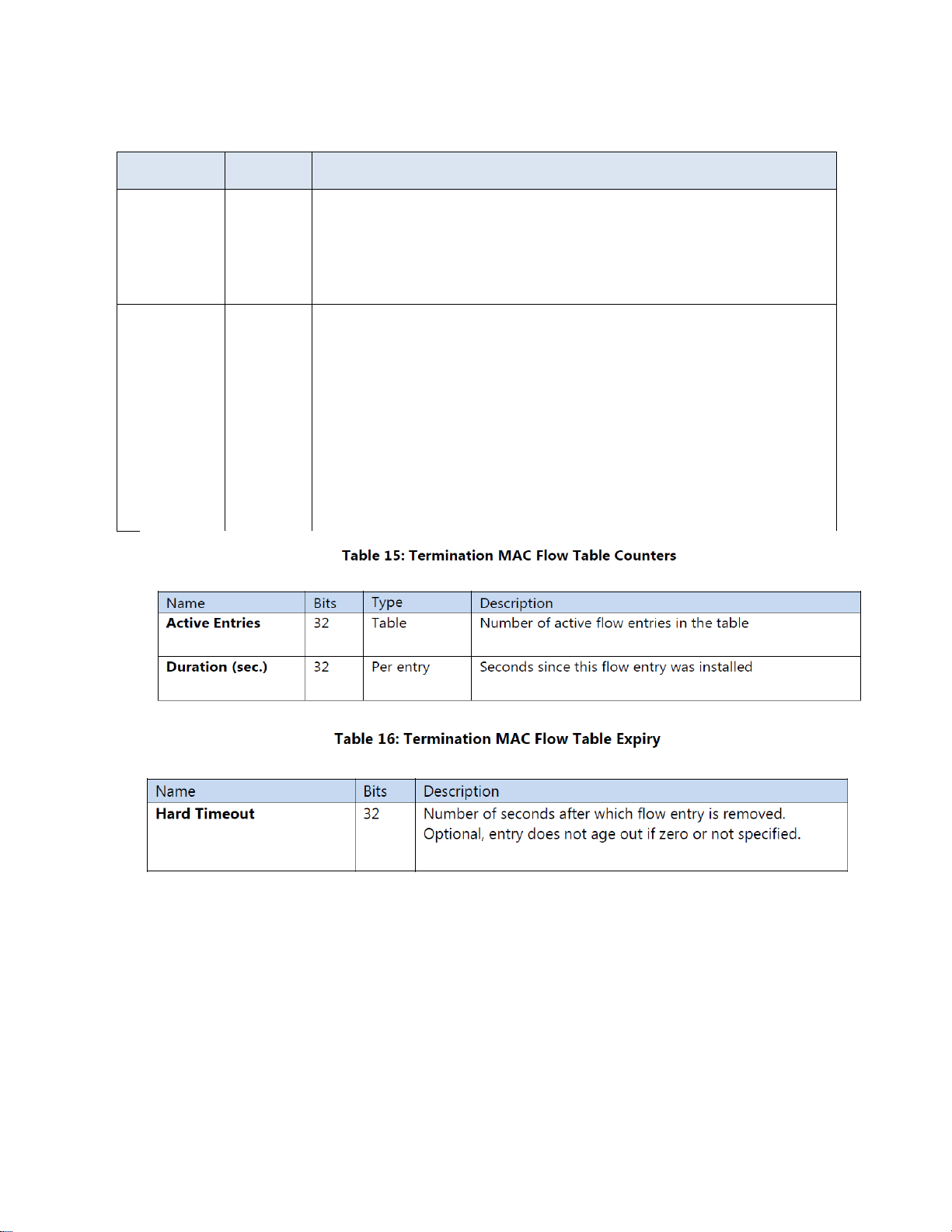
specified in the action set. The Routing Flow Table counters are listed in Table 28.
Unicast Routing Flow Table expiry provisions are shown in Table 29.
25
Page 26
Field
Bits
Maskable
Optional
Description
ETH_TYPE
16
N
o
No
Must be 0x0800. Required prerequisite.
VLAN_VID
16
N
o
No
VLAN id
VRF
16
N
o
Yes
VRF.
IPV4_SRC
32
Y
e
s
Yes
Cannot be bit masked, but can be omitted.
IPV4_DST
32
Y
e
s
No
Must be an IPv4 multicast group address.
Field
Bits
Maskable
Optional
Description
ETH_TYPE
16
No
No
Must be 0x86dd. Required
prerequisite.
VLAN_VID
16
No
No
VLAN id
VRF
16
No
Yes
VRF.
IPV6_SRC
128
Yes
Yes
Cannot be bit masked, but
can be omitted.
IPV6_DST
128
Yes
No
Must be an IPv6 multicast
group address.
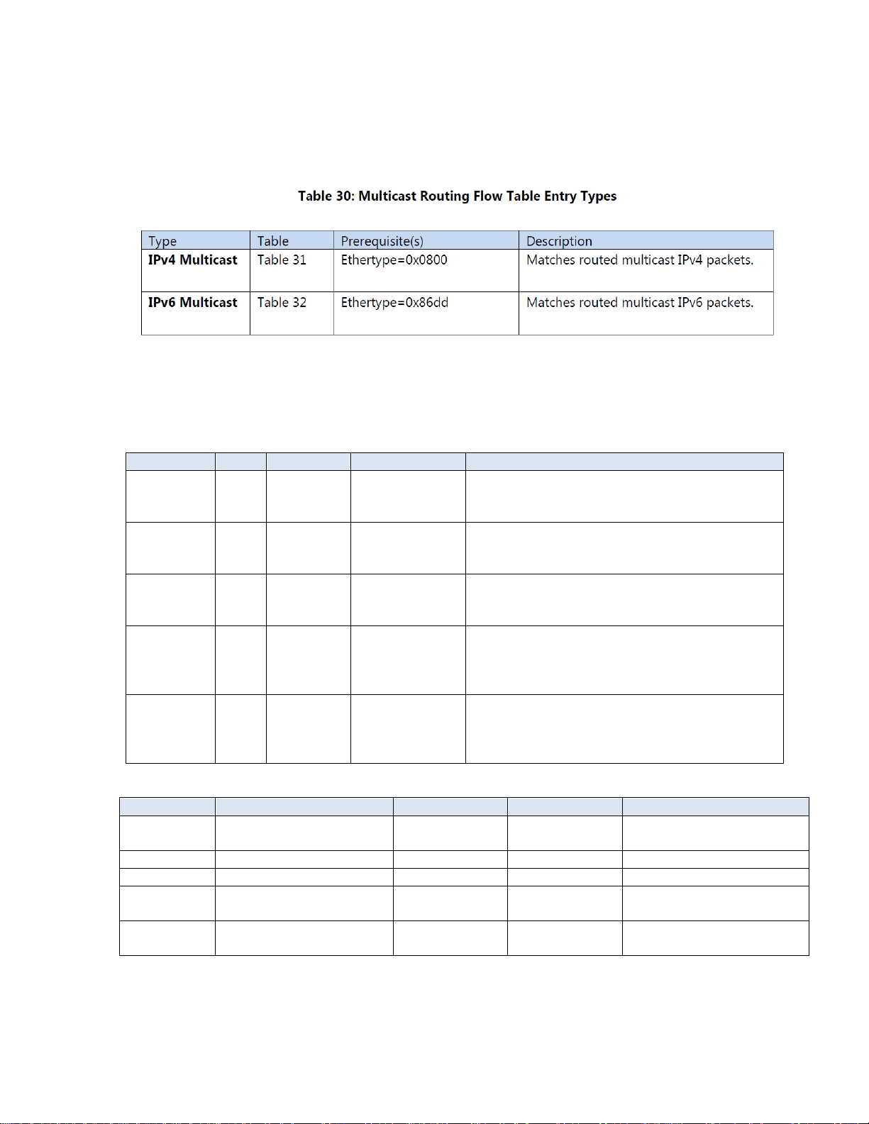
4.3.2.6 Multicast Routing Flow Table
The Multicast Routing Flow Table supports routing for IPv4 and IPv6 multicast packets.
The Multicast Routing Flow Table is also organized as two mutually exclusive logical sub tables by IP protocol,
and supports the flow entry types listed in Table 30.
4.3.2.6.1 Match Criteria, Instructions, Actions/Action List/Action Set, Counters, Flow Expiry
Match fields for flow entry types are described in the following tables.
Table 31. Multicast Routing Flow Table IPv4 Match Fields
Table 32. Multicast Routing Flow Table IPv6 Match Fields
Default next table on miss is the ACL Policy Flow Table.
26
Page 27
Name
Argument
Description
Write
Actions
Action set
Only the actions in Table 34 can be specified.
GotoTable
Table
Must be the Policy ACL Flow Table. In the event that there is no group
entry referenced and no next table specified, the packet will be
dropped.
Name
Argument
Description
Group
Group ID
Must be a DNOS-OF L3 Multicast group entry with the forwarding
VLAN ID as a name component.
Decrement
TTL and do
MTU check
-
MTU check is a vendor extension. An invalid TTL (zero before or
after decrement) is always dropped and a copy sent to the CPU
for forwarding to the CONTROLLER. Similarly, a packet that
exceeds the MTU is dropped and a copy sent to the
CONTROLLER. Required.
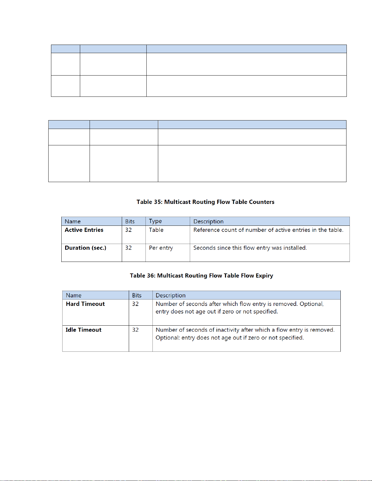
Table 33: Multicast Routing Flow Table Instructions
Other instruction types, specifically Apply Actions, are not supported.
Table 34: Multicast Routing Flow Table Actions
Note: The group entry includes the decrement TTL and MTU check actions.
27
Page 28

Type
Table
Prerequisite
Description
IPv4 VLAN
Table 38
Ethertype != 0x86dd
IN_PORT is a physical port.
Matches packers by VLAN ID except for IPv6.
VLAN ID is optional but must be nonzero if
supplied.
IPv6 VLAN
Table 39
Ethertype = 0x86dd
Matches only IPv6 packets by VLAN ID. VLAN ID
is optional but must be nonzero if supplied.
Field
Bits
Maskable
Optional
Description or Prerequisite
IN_PORT
32
No
Yes
Physical or logical ingress port.
ETH_SRC
48
Yes
Yes
Ethernet source MAC
ETH_DST
48
Yes
Yes
Ethernet destination MAC
ETH_TYPE
16
No
Yes
Any value except 0x86dd. Explicit prerequisite
must be 0x800 if IP fields are to be matched.
VLAN_VID
16
Yes
Yes
VLAN id. Cannot be masked for a VLAN bridging
rule that redirects to a different L2 output group.
Only applicable to VLAN flow entry types.
VLAN_PCP
3
No
Yes
802.1p priority field from VLAN tag. Always has a
value, will be zero if packet did not have a VLAN
tag.
VLAN_DEI
1
No
Yes
802.1p drop eligibility indicator field from VLAN
tag. Always has a value, will be zero if packet did
not have a VLAN tag.
VRF
16
No
Yes
VRF.
IPV4_SRC
32
Yes
Yes
Matches SIP if Ethertype = 0x0800
ARP_SPA
32
Yes
Yes
Matches ARP source protocol address if Ethertype
= 0x0806
IPV4_DST
32
Yes
Yes
Matches DIP if Ethertype = 0x0800
IP_PROTO
8
No
Yes
IP protocol field from IP header if Ethertype =
0x0800
4.3.2.7 Policy ACL Flow Table
The Policy ACL Flow Table supports wide, multi-field matching. Most fields can be wildcard matched, and
explicit priority must be included in all flow entry modification. This is the preferred table for matching
BPDU and ARP packets. It is also the only table where QoS actions are available.
The Policy ACL Flow Table is organized as mutually exclusive logical sub tables. Flow entries in the IPv6
logical tables match only IPv6 packets by VLAN ID. The non-IPv6 logical table matches any packet except
for IPv6 packets by VLAN ID. By OpenFlow single-entry match semantics, since the Policy ACL Flow Table
is considered a single table, a packet can match, at most, one rule in the entire table.
Note: The Ethertype prerequisite must be explicitly provided and cannot be masked.
The default on table miss is to do nothing. The packet will be forwarded using the output or group in the
action set, if any. If the action set does not have a group or output action the packet is dropped. The
Policy ACL Flow Table supports the flow entry types listed in Table 37.
Table 37: Policy ACL Flow Table Entry Types
4.3.2.7.1 Match Criteria, Instructions, Actions/Action List/Action Set, Counters, Flow Expiry
The available match fields for Policy ACL Flow Table flow entry types are as described in the following tables.
Table 38: Policy ACL Flow Table IPv4 Match Fields
28
Page 29

IP_DSCP
6
No
Yes
Bits 0 through 5 of the IP ToS Field as defined in
RFC 2474 if Ethertype = 0x0800
IP_ECN
2
No
Yes
Bits 6 through 7 of the IP ToS Field as defined in
RFC 3168 if Ethertype = 0x0800
TCP_SRC
16
No
Yes
If Ethertype = 0x0800 and IP_PROTO = 6
UDP_SRC
16
No
Yes
f Ethertype = 0x0800 and IP_PROTO = 17
SCTP_SRC
16
No
Yes
If Ethertype = 0x0800 and IP_PROTO = 132
ICMPV4_TYPE
8
No
Yes
If Ethertype = 0x0800 and IP_PROTO = 1
TCP_DST
16
No
Yes
If Ethertype = 0x0800 and IP_PROTO = 6
UDP_DST
16
No
Yes
if Ethertype = 0x0800 and IP_PROTO = 17
SCTP_DST
16
No
Yes
If Ethertype = 0x0800 and IP_PROTO = 132
ICMPv4_CODE
8
No
Yes
If Ethertype = 0x0800 and IP_PROTO = 1
Field
Bits
Maskable
Optional
Description
IN_PORT
32
No
Yes
Physical or logical ingress port.
ETH_SRC
48
Yes
Yes
Ethernet source MAC
ETH_DST
48
Yes
Yes
Ethernet destination MAC
ETH_TYPE
16
No
Yes
Must be 0x86dd
VLAN_VID
16
Yes
Yes
VLAN id. Cannot be masked for a
VLAN bridging rule that redirects to
a different L2 output group. Only
applicable to VLAN flow entry
types.
\VLAN_PCP
3
No
Yes
802.1p priority field from VLAN tag.
Always has a value, will be zero if
packet did not have a VLAN tag.
VLAN_DEI
1
No
Yes
802.1p drop eligibility indicator field
from VLAN tag. Always has a value,
will be zero if packet did not have a
VLAN tag.
VRF
16
No
Yes
VRF
IPV6_SRC
128
Yes
Yes
Matches IPv6 SIP
IPV6_DST
128
Yes
Yes
Matches IPv6 DIP
IP_PROTO
8
No
Yes
Matches IPv6 Next header
IPV6_FLABEL
20
No
Yes
Matches IPv6 flow label
IP_DSCP
6
No
Yes
Bits 0 through 5 of the IP ToS Field
as defined in RFC 2474 if Ethertype
= 0x86dd
IP_ECN
2
No
Yes
Bits 6 through 7 of the IP ToS Field
as defined in RFC 3168 if Ethertype
= 0x86dd
TCP_SRC
16
No
Yes
If Ethertype = 0x86dd and
IP_PROTO = 6
UDP_SRC
16
No
Yes
If Ethertype = 0x86dd and
IP_PROTO = 17
SCTP_SRC
16
No
Yes
If Ethertype = 0x86dd and
IP_PROTO = 132
ICMPV6_TYPE
8
No
Yes
If Ethertype = 0x86dd and
IP_PROTO = 58
TCP_DST
16
No
Yes
If Ethertype = 0x86dd 00 and
IP_PROTO = 6
Table 39: Policy ACL Flow Table IPv6 Match Fields.
29
Page 30

UDP_DST
16
No
Yes
If Ethertype = 0x86dd and
IP_PROTO = 17
SCTP_DST
16
No
Yes
If Ethertype = 0x86dd and
IP_PROTO = 132
ICMPv6_CODE
8
No
Yes
If Ethertype = 0x86dd and
IP_PROTO = 58
Name
Argument
Description
Apply Actions
Action list
Optional. Only the actions in Table 41 can be specified.
Clear Actions
Used to clear the action set for dropping the packet. Cannot
be combined with write actions.
Write Actions
Action set
Only the actions in Table 42 or Table 43 can be specified,
depending on rule type.
Name
Argument
Description
SetField
Traffic
Class
Name
Argument
Description
Group
Group
Sets output group entry for processing the packet after this table.
Group must exist, be consistent with the type of rule and packet;, and
can be any of: L2 Interface, L2 Rewrite, L2 Multicast, L3 Unicast, L3
Multicast, or L3 ECMP; must respect VLAN id naming conventions. In
particular, if the output is an L2 Rewrite group that does not set the
VLAN id, the L2 Interface group it references must be consistent with
the VLAN id in the matched flow entry.
SetQueue
Queue-id
Determines queue to be used when packet is finally forwarded. Zero
indicates the default queue. Cannot be used together with Set Traffic
Class in the action list.
Notes:
IPv6 Neighbor Discovery field matching is not supported in this version of DNOS-OF.
Not all IPv6 match fields are supported on all platforms.
DNOS-OF permits bit masking L4 source and destination ports, as well as ICMP code. The OpenFlow does
not require these to be maskable.
The only instruction is write actions. Since there is no next table, there can be no Goto-Table or Write
Metadata instructions.
Table 40: Policy ACL Flow Table Instruction Set
The packet is dropped if there is no group action that specifies output ports, since there is no next table.
Note: Apply-actions to CONTROLLER would be used in order to output the packet to the CONTROLLER
reserved port, rather than an output action in the write-actions action set.
The Policy ACL Flow Table supports the actions listed in Table 41.
Table 41: Policy ACL Flow Table Action List Actions
The Policy ACL Flow Table action set supports the actions listed in Table 70 for VLAN match rule types, and
the actions in Table 71 for tunnel match rule types.
Table 42: Policy ACL Flow Table VLAN Flow Entry Action Set
30
Page 31

As with Unicast and Multicast Routing Flow Table actions, the decrement TTL and MTU checks are encoded by
referencing an L3 Unicast or Multicast group entry. Note that if the group entry type is L2 Interface. L2
Rewrite, or L2 Multicast then these checks will not be done.
The Policy ACL Flow Table counters are listed in Table 43. These are applicable to VLAN flow entries.
Policy ACL Flow Table expiry provisions are shown in Table 44. Each flow entry can have its own time-out
values.
31
Page 32

Field
Bits
Description
Index
[27:0]
28-bit field, used to uniquely identify a group entry of the
indicated type. May be used to further encode properties of the
group entry, such as VLAN ID.
Type
[32:38]
-bit field that encodes the entry type, one of:
0: DNOS-OF L2 Interface
1: DNOS-OF L2 Rewrite
2: DNOS-OF L3 Unicast
3: DNOS-OF L2 Multicast
4: DNOS-OF L2 Flood
5: DNOS-OF L3 Interface
6: DNOS-OF L3 Multicast
7: DNOS-OF L3 ECMP
4.4 Group Table
Most forwarding actions are embodied in group table entries. DNOS-OF supports a defined set of group table
entry types, effectively partitioning the group table into logical sub tables.
Each group entry has an identifier, type, counters, and one or more action buckets. OpenFlow has a single
monolithic group table, but DNOS-OF differentiates among types of group entries. For this purpose, DNOSOF encodes the group entry type in a group entry identifier field. The basic naming convention followed is
illustrated in Table 45.
Table 45: DNOS-OF Group Table Entry Identifier Naming Convention
DNOS-OF performs consistency checks on the group entry type when a group action is used in a flow entry.
The index scheme varies by DNOS-OF group entry type and is described in the following sections.
32
Page 33

4.4.1 DNOS-OF flow tables
DNOS-OF flow tables accommodate specific types of flow entries with associated semantic rules,
including constraints such as which match fields are available, which instructions and actions are
supported, how priorities can be assigned to flow entries, which next table(s) flow entries can go to, and
so forth. The flow tables conform to the OpenFlow 1.3.4 specification. In addition to normal flows, two
types of special flow entries are supported as follows:
- Built-in: Built-in flow entries come preinstalled in specific tables. They are visible to the controller but
cannot be modified or deleted. Built-in entries have preassigned match fields, priority, and cookie values.
They are typically used for default entries.
- Automatic: Automatic flow entries are added by the switch as a side effect of the controller adding a flow
entry. They are visible to the controller but cannot be directly modified or deleted except by modifying or
deleting the rule that caused the automatic entry to be added. Match fields and priority are predetermined,
and the switch assigns the same cookie value as the initiating rule.
In addition to flow tables, DNOS-OF defines a set of group table entry types. The OpenFlow 1.3.4
specification defines four types of groups: indirect, all, select, and fast failover. DNOS-OF further types
group entries according to how they can be used in packet flows. This is done using specific naming
conventions, properties, and supported action buckets. All DNOS-OF group table entry types can be
programmed using OpenFlow 1.3.4 as long as group mods respect the typing conventions.
One motivation for group typing is supporting fundamental differences in use-case requirements. For
example, in order to support “one-arm” routing using group table entries, there needed to be a way to
override OpenFlow’s default source removal and allow routing back to the IN_PORT. This was
accomplished by defining L3 group entry types with different properties from L2 groups. Group entry
typing is also useful to enforce constraints on group entry chains and for Virtual Local Area Network
(VLAN) configuration on physical ports.
Remember that DNOS-OF tables are programming abstractions and do not necessary directly correspond
one-to-one with hardware tables. However, they are designed to faithfully capture both use-case
requirements and the hardware packet flow semantics, while being straightforward to program from
standard controllers.
Users must program flow tables and group entries according to the allowed entry types. The DNOS-OF
validates calls and returns errors if constraints and/or conventions are violated. This includes the
requirement that objects must exist before they can be referenced from other objects. The OpenFlow
agent that interfaces to OF-DPA may also do some argument validation and execute local iterative
procedures.
Many forwarding and editing actions for encapsulation/push and field modify are programmed using one
or more action buckets in group table entries. This not only proves to be a very efficient and modular
programming approach, in that the controller can optimize hardware resources better than the switch, but
the controller intrinsically has more CPU power and memory than the control processor on a typical
switch for this task. The controller also understands what the application is trying to do, especially when
programming requires updating multiple tables. However, when compared with OpenFlow 1.0
programming, it may require more messages between the controller and switches, since more objects
need to be programmed. It also potentially requires the controller to keep track of more switch state,
although this state can be interrogated as needed.
4.4.2 DNOS-OF L2 Interface Group Entries
L2 Interface Group entries are of OpenFlow indirect type, with a single action bucket.
DNOS-OF L2 Interface group entries are used for egress VLAN filtering and tagging. The identifier
convention is shown in Table 94. If a specific set of VLANs is allowed on a port, appropriate group entries
must be defined for the VLAN and port combinations.
33
Page 34

Field
Argument
Description
Output
Port
Physical output port.
Pop VLAN
None
Pop the VLAN tag before sending the packet.
Set Field
DSCP
Static DSCP value for IP packets
Set Field
VLAN PCP
Static 802.1p value
Set-Field
VLAN DEI
Static 802.1p value
4.4.2.1 Naming Convention
Table 46 details the DNOS-OF L2 Interface group entry identifier subfields that encode combinations of egress
port and VLAN ID.
4.4.2.2 Action Buckets
The single action bucket specifies the output port, and whether or not the packet is egressed tagged.
Although the pop action is a NOP if the packet has no VLAN tag, packets should always have a VLAN tag
when the actions in the output group table are applied.
Note: If the packet came in untagged and a port VLAN was assigned, a VLAN tag was pushed as a VLAN Flow
Table action.
Table 47: DNOS-OF L2 Interface Group Entry Bucket Actions
Clearly DNOS-OF L2 Interface group entries must be defined before being used. DNOS-OF maintains
reference counts for used entries, and an entry cannot be deleted if it is referenced by a flow entry or anothe r
group.
4.4.2.3 Counters
DNOS-OF L2 Interface group entry counters are as shown in Table 48.
34
Page 35

Field
Argument
Description
Group
Group
entry
Must chain to a L2 Interface group entry.
Required.
Set Field
MAC_SRC
Re-write the source MAC. Optional.
Set Field
MAC_DST
Re-write the destination MAC. Optional.
Set Field
VLAN-id
Re-write the VLAN id. Optional.
4.4.3 DNOS-OF L2 Rewrite Group Entries
DNOS-OF L2 Rewrite group entries are of indirect type and have a single action bucket. They are used when it
is desired to modify Ethernet header fields for bridged packets. Use of a DNOS-OF L2 Rewrite group entry is
optional, and can only be a Policy ACL Flow Table action.
DNOS-OF L2 Rewrite actions are optional with the exception of group. This permits a DNOS-OF L2 Rewrite
group entry to selectively modify the source MAC, destination MAC, and/or VLAN ID.
If a Set Field action sets the VLAN id, the VLAN id must be the same as in a chained L2 Interface group
entry. Note that if the VLAN id is not rewritten, the VLAN id in the L2 Interface group entry must be the
same as the VLAN id matched in the Policy ACL Flow Table flow entry that forwarded to the rewrite group.
4.4.3.1 Naming Convention
Table 49 details the DNOS-OF L2 Rewrite group entry identifier subfields that encode the type and VLAN ID.
4.4.3.2 Action Buckets
The single action bucket specifies the output group for forwarding the packet and optional Ethernet header
modifications.
4.4.3.3 Counters
Chained group entries must be defined before being used. DNOS-OF maintains reference counts for used
entries, and a group entry cannot be deleted if it is referenced by a flow entry or another group.
DNOS-OF L2 Rewrite group entry counters are as shown in Table 51 for completeness.
35
Page 36

Field
Argument
Description
Group
Group-id
Must chain to a L2 Interface group entry. ALLOW-IN_PORT permits the
chained group entry output action to include the packet IN_PORT.
Required.
Set Field
MAC_DST
Write the next hop destination MAC. Required.
Set Field
MAC_SRC
Write the source MAC corresponding to the L3 output interface. Required.
4.4.4 DNOS-OF L3 Unicast Group Entries
DNOS-OF L3 Unicast group entries are used to supply the routing next hop and output interface for packet
forwarding. To properly route a packet from either the Routing Flow Table or the Policy ACL Flow Table, the
forwarding flow entry must reference a DNOS-OF L3 Unicast Group entry.
DNOS-OF L3 Unicast automatically includes the ALLOW-IN_PORT vendor extension property to allow packets
to be sent out IN_PORT. This property overrides the OpenFlow default behavior, which is to not forward a
packet to IN_PORT, and is inherited by chained group entries. It is not visible to the controller and hence
cannot be modified or read.
All packets must have a VLAN tag. A chained L2 Interface group entry must be in the same VLAN as assigned
by the DNOS-OF L3 Unicast Group entry.
4.4.4.1 Naming Convention
The naming convention for DNOS-OF L3 Unicast Group entries is shown in Table 52.
4.4.4.2 Action Buckets
The single action bucket is as shown in Table 53. All actions are required.
Table 53: DNOS-OF L3 Unicast Bucket Actions
36
Page 37

Set Field
VLAN-id
Write the VLAN id corresponding to the L3 output interface. Required.
4.4.4.3 Counters
The DNOS-OF L3 Unicast group entry counters are as shown in Table 54.
4.4.5 DNOS-OF L2 Multicast Group Entries
DNOS-OF L2 multicast group entries are of OpenFlow ALL type. There can be multiple action buckets, each
referencing an output port by chaining to a DNOS-OF L2 Interface Group entry.
Note: By OpenFlow default, a packet cannot be forwarded back to the IN_PORT from which it came in. An
action bucket that specifies the particular packet’s ingress port is not evaluated.
All of the DNOS-OF L2 Interface Group entries referenced by the DNOS-OF Multicast Group entry, and the
DNOS-OF Multicast Group entry itself, must be in the same VLAN.
4.4.5.1 Naming Convention
DNOS-OF L2 Multicast group entries use the naming convention in Table 55.
4.4.5.2 Action Buckets
The contents of DNOS-OF L2 Multicast Group entry buckets can contain only the value shown in Table 56.
37
Page 38

4.4.5.3 Counters
The L2 Multicast group entry counters are as shown in Table 57.
4.4.6 DNOS-OF L2 Flood Group Entries
The OF-DPA L2 Flood Group entries are used by VLAN Flow Table wildcard (destination location forwarding,
or DLF) rules. Like OF-DPA L2 Multicast group entry types they are of OpenFlow ALL type. The action buckets
each encode an output port. Each OF-DPA L2 Flood Group entry bucket forwards a replica to an output port,
except for packet IN_PORT.
The main difference from OF-DPA L2 Multicast Group entries is how they are processed in the hardware.
All of the DNOS-OF L2 Interface Group entries referenced by the OF-DPA Flood Group entry, and the OF-DPA
Flood Group entry itself, must be in the same VLAN.
Note: There can only be one DNOS-OF L2 Flood Group entry defined per VLAN.
4.4.6.1 Naming Convention
DNOS-OF L2 Flood group entries follow the naming convention shown in Table 58.
38
Page 39

4.4.6.2 Action Buckets
The contents of the DNOS-OF L2 Flood Group Entry action buckets can contain only the values shown in
Table 59.
4.4.6.3 Counters
The DNOS-OF L2 Multicast group entry counters are as shown in Table 60.
4.4.7 DNOS-OF L3 Interface Group Entries
DNOS-OF L3 interface group entries are of indirect type and have a single action bucket. They are used to
supply outgoing routing interface properties for multicast forwarding. For unicast forwarding, use of DNOSOF L3 Unicast group entries is recommended.
DNOS-OF L3 Interface uses the ALLOW-IN-PORT vendor extension that permits packets to be sent out
IN_PORT.
The VLAN id in the name must be the same as the VLAN_VID assigned in the Set Field action and the VLAN
id in the name of the chained OF-DPA L2 Interface group.
39
Page 40

Field
Argument
Description
Group
Group entry
Must chain to a L2 Interface group entry. This group entry can output
the packet to IN_PORT. The VLAN id component of the chained group
entry’s name must match the Set Field value for VLAN id.
Set
Field
MAC_SRC
Write the source MAC corresponding to the L3 output interface.
Set
Field
VLAN-id
Write the VLAN id corresponding to the L3 output interface.
4.4.7.1 Naming Convention
Table 61 details the DNOS-OF L3 Interface group entry identifier subfields.
4.4.7.2 Action Buckets
The single action bucket specifies the MAC_SRC, VLAN_VID, TTL decrement action, and an output group for
forwarding the packet. All actions are required.
Table 62: DNOS-OF L3 Interface Group Entry Bucket Actions
Referenced group entries must be defined before being used. DNOS-OF maintains reference counts for
used entries, and an entry cannot be deleted if it is referenced by a flow entry or another group.
4.4.7.3 Counters
DNOS-OF L3 Interface group entry counters are as shown in Table 63 for completeness.
40
Page 41

4.4.8 DNOS-OF L3 Multicast Group Entries
DNOS-OF L3 Multicast group entries are of OpenFlow all type. The action buckets describe the interfaces to
which multicast packet replicas are forwarded.
IP multicast packets are forwarded differently, depending on whether they are switched or routed. Packets
must be switched in the VLAN in which they came in and cannot be output to IN_PORT. Packets that are
multicast in other VLANs must be routed and must be allowed to egress via IN_PORT. This difference is
reflected in the actions that are programmed in the action buckets.
Note that any chained DNOS-OF L2 Interface Group entries must be in the same VLAN as the DNOS-OF
L3 Multicast group entry. However chained DNOS-OF L3 Interface Group entries must be in different
VLANs from the DNOS-OF L3 Multicast Group entry, and from each other.
41
Page 42

Field
Argument
Description
Group
Group-id
Can chain to one of: L3 Interface; L2
Interface. Chained group entry names
must conform to the VLAN id
requirements above.
4.4.8.1 Naming Convention
The naming convention for DNOS-OF L3 Multicast Group entries is shown in Table 64.
4.4.8.2 Naming Convention
The action buckets contain the values shown in Table 65.
Table 65: DNOS-OF L3 Multicast Bucket Actions
4.4.8.1 Counters
The DNOS-OF L3 Multicast group entry counters are as shown in Table 66.
4.4.9 DNOS-OF L3 ECMP Group Entries
DNOS-OF L3 ECMP group entries are OpenFlow type SELECT. The action buckets reference the DNOS-OF L3
Unicast group entries that are members of the multipath group for ECMP forwarding.
A DNOS-OF L3 ECMP Group entry can be specified as a routing target instead of a DNOS-OF L3 Unicast
Group entry. Selection of an action bucket for forwarding a particular packet is hardware specific.
42
Page 43

Field
Bits
Description
Id
[27:0]
Used to differentiate OF-DPA L3 ECMP
group entries.
Type
[31:28]
7 (OF-DPA L3 ECMP)
Field
Argument
Description
Group
Group-id
May chain to a DNOS-OF L3
Unicast.
4.4.9.1 Naming Convention
The naming convention for DNOS-OF L3 ECMP Group entries is as shown in Table 67.
Table 67: DNOS-OF L3 ECMP Group Entry Naming Convention
4.4.9.2 Action Buckets
The action buckets contain the single value listed in Table 68.
Table 68. DNOS-OF L3 ECMP Group Entry Bucket Actions
4.4.9.3 Counters
The DNOS-OF L3 ECMP group entry counters are as shown in Table 69.
4.4.10 Fast Failover Group Entries
DNOS-OF does not support meter bands in Release 1.0.
4.4.11 Meters
DNOS-OF does not support meter bands in Release 1.0.
43
Page 44

Type
Numbering
Description
Physical
0x0000 xxxx
Physical (front panel) port
Reserved
0xFFFF xxxx
Reserved ports as defined in the OpenFlow specification.
Name
Bits
Configurable?
Description
Number
32
No
ifNum (should be the same as in interface MIB)
Hardware
Address
48
No
MAC address assigned to port.
Name
128
Yes
16-byte string name (should be the same as in
interface MIB)
Configured
State
32
Yes
Port is administratively up (0) or down (1)
Current
State
32
No
Port link (operational) state is up (0), live (4), or down
(1). Generally a port is live if operationally up.
Current
Features
32
No
DNOS-OF supports the feature bitmap in Table 74. A
one indicates the feature is currently active.
Advertised
Features
32
No
DNOS-OF supports the feature bitmap in Table 74. A
zero bit indicates the feature is not available.
Supported
Features
32
No
DNOS-OF supports the features in Table 74. A zero bit
indicates the feature is not supported.
Peer
Features
32
No
Bitmap indicating capabilities advertised by the peer
from Table 74.
Current
Speed
32
No
Current port bitrate in kbps
Max Speed
32
No
Maximum port bitrate in kbps
4.4.12 Ports
This section lists the DNOS-OF supported properties for physical and reserved ports.
4.4.12.1 Physical Ports
DNOS-OF supports physical ports that are available on specific target platforms. Ports are identified using a
32-bit ifNum value. The most significant two bytes indicate the type of port. Only physical ports are
supported in DNOS-OF. Physical ports are front panel ports on the abstract switch.
DNOS-OF supports the physical port features listed in Table 73.
Table 70: Port Type Numbering Conventions
Table 73. DNOS-OF Port Features
Note: Not all of the above may be applicable to the LOCAL or CONTROLLER reserved port.
Table 74 shows the port features bitmap referenced from the table above and the OpenFlow Port Features
subclasses in Figure 16.
44
45
Page 45

Page 46

4.4.12.2 Counters
DNOS-OF supports the port counters listed in Table 75.
46
Page 47

Name
Required
Description
Use
Supported?
ALL
Yes
Required but not supported in
DNOS-OF.
Output
No
IN_PORT
Yes
Used to send packets to the ingress
port to override OpenFlow default
behavior. DNOS-OF uses group
ALLOW-IN_PORT property instead.
Not to be confused with the
IN_PORT match field.
Output
No
CONTROLLER
Yes
The OpenFlow controller. Output
destination for sending packets to
the Agent which, in turn, sends to
the OpenFlow Controller in a
Packet_In message. Also can
optionally be used to indicate the
source of packets received by the
Agent in a Packet_Out message.
Input or
output
Yes
TABLE
Yes
Used in Packet_Out messages to
indicate that the packet must be
recirculated through the pipeline.
Must always be the first table in the
pipeline if specified.
Output
Yes
ANY
Yes
Special value used in some requests.
Neither
Yes
LOCAL
No
Used to send and receive packets
with the local Network Protection
App. Analogous to Controller but
the destination is a local OAM
engine rather than the Agent. The
exact mechanism is
implementation-dependent.
Input or
output
Yes, for OAM
NORMAL
No
Not supported in OF-DPA
Output
No
FLOOD
No
Not supported in OF-DPA
Output
No
4.4.12.3 Reserved Ports
DNOS-OF supports the reserved ports listed in Table 76.
Table 76. DNOS-OF Reserved Ports
47
Page 48

4.4.13 Vendor Extension Features
In many cases the vendor extension features only affect the OpenFlow abstract switch and can be
accommodated by the existing OpenFlow 1.3.4 protocol. In others, an OpenFlow 1.3.4 agent and compatible
controller can be extended using the OpenFlow Experimental facility to add new protocol elements as needed.
DNOS-OF provides vendor extensions for source MAC learning, and L3 forwarding IN_PORT control.
4.4.13.1 Source MAC Learning
OF-DPA provides vendor extensions for source MAC learning, L3 forwarding IN_PORT control, MPLS and OAM
actions and pipeline match fields, and new ancillary object types.
In many cases the vendor extension features only affect the OpenFlow abstract switch and can be
accommodated by the existing OpenFlow 1.3.4 protocol. In others, an OpenFlow 1.3.4 agent and compatible
controller can be extended using the OpenFlow Experimental facility to add new protocol elements as needed.
4.4.13.2 Group Properties
DNOS-OF adds the vendor extension property “ALLOW-IN_PORT” to DNOS-OF L3 Interface and L2
Loopback group entries. This property applies to the group entry and to any referenced group entries. L3
Interface and L2 Loopback group entries automatically come with the property set, and it cannot be
overridden. This obviates the need for special protocol support in OpenFlow 1.3.4.
48
Page 49

4.5 OpenFlow Single Table Programming Supported by DNOS-OF (NEC
PF6800 PFC Cluster Controller compatibility mode)
4.5.1 Bridging and Routing Functions in NEC
While the same set of tables shown above that are used and exposed in OF-DPA exist in single table NEC
mode, only a single table is exposed to the NEC PF6800 controller. For DNOS-OF 1.1, only NEC OF1.3+ mode
is supported. Support for the recently released NEC OEF multi table mode is planned for a later release of
DNOS-OF.
In NEC OF1.3+ single table mode, the controller only communicates with 1 table in the switch. The of-switch
application in DNOS-OF converts the table 0 incoming flow table programming instructions into the
appropriate flow table programming instructions for the multiple tables shown in the diagram above.
One of the main differences between the Ryu controller in multi table mode and the NEC controller in single
table mode is how individual flow instructions are programmed. In multi table mode the application
programmer is responsible for all flow table installation and programming, specifying the individual match
criteria, instructions and actions. However in single table mode the individual flow match criteria, instructions
and actions are all programmed by the NEC controller. The application programmer only works with virtual
constructs such as virtual tenant network (VTN) endpoint stations, virtual bridges (vBridges), and virtual routers
(vRouters) within the NEC environment. The physical network is separated from the virtual network, and all
physical network flow table programming is handled automatically by the controller.
49
Page 50

The following is a sample physical topology showing some of the components in the PF6800 PFC cluster
controller. There are 4 separate networks used in the PF6800 cluster controller, as shown below in these extracts
from the NEC PFC installation guide.
50
Page 51

The virtual components of the PFC network are shown below. The virtual router, virtual bridges and endpoints are
controlled by the application programmer, while the actual OpenFlow flow table programming of match criteria,
instructions and actions are handled by the controller. This transparency to the application programmer is a large
part of what adds value to the NEC PF6800 PFC cluster controller.
51
Page 52

Below are some examples showing the PF6800 web application GUI used in testing the PFC controller. The first
one shows a simple Layer 2 construct, a virtual bridge (vBridge), with 2 external traffic sources showing end to end
traffic running through the switch.
52
Page 53

The vBridge is combined with external data sources (vExternal connections to vInterfaces, as shown below) in order to
drive data across the virtual switch (vBridge). The vInterface definition screen is shown below.
53
Page 54

vBridges and vInterface data sources can be combined into Layer 3 vRouter constructs as shown in the examples below.
54
Page 55

These examples are only shown here for reference. For full documentation and detail on working with the PFC
controller see the NEC documentation and manuals.
55
Page 56

5 Installation, Configuration, Deployment
Since the target delivery mechanism is the web download, the only thing needed other than the actual N
series switch is the DNOS-OF .STK firmware image file. This section shows how it is downloaded,
configured and started.
This firmware image file is identical to the standard N Series firmware image file format and is loaded and
enabled the same way. The user can switch back and forth between the standard N-Series image .STK file
and the DNOS-OF .STK file the same way they do now between versions of the N-Series firmware with
“boot system <primary/backup>” command and then reloading the switch firmware.
Dell Networking N-series switches can currently store up to two software images in the flash partitions.
The dual image feature allows you to upgrade the switch without deleting the older software image. You
designate one image as the active image and the other image as the backup image.
The DNOS-OF switch firmware is obtained at www.dell.com/support
5.1 View current installed OS
From a terminal or the serial console use the show version command as below:
> sh ver
Machine Description............... Dell Networking Switch
System Model ID................... N3024
Machine Type...................... Dell Networking N3024
Serial Number..................... CN0PDJ93282984CT0290A02
Manufacturer...................... 0xbc00
Burned In MAC Address............. f8:b1:56:69:9d:9b
SOC Version....................... BCM56342_A0
HW Version........................ 5
CPLD Version...................... 13
unit active backup current-active next-active
---- ----------- ----------- -------------- -------------1 6.2.0.5 6.2.0.5 7.28.16.0 6.2.0.5
You can currently download system images to the switch by using TFTP, or by copying files to and from a
USB Flash drive that is plugged into the USB port on the front panel of the switch as shown in the
following section.
56
Page 57

5.2 Install DNOS-OF
To install from a TFTP server, copy the DNOS-OF image to the download directory of your TFTP server, then
from the terminal or serial console of the switch use the “copy” command as shown below. This example puts
the firmware into the backup partition on the switch:
ZBA123_console> copy tftp://<IP address of TFTP server>/DNOS-OF-xx.yy.zz.bb.stk <backup>
To install from USB, plug the USB stick containing the image into the switch and use the following command:
ZBA123_console> copy usb://<path to image>/DNOS-OF-xx.yy.zz.bb.stk <backup>
Once the file is copied, point the boot loader to the partition where the DNOS-OF firmware image was copied
by using the “boot” command as shown below. This example points the boot loader to the backup partition
where the new DNOS-OF image was just copied to and then issues a reload to boot into the new firmware:
ZBA123_console> boot system <backup>
ZBA123_console> reload
5.3 Configure Management Access
You can use any of the following methods to manage the switch and access the CLI:
o Telnet client
o SSH client
o direct serial console connection
The CLI syntax and semantics for all of the CLI commands are shown in Appendix A.
DNOS-OF comes initially configured with DHCP enabled, so if it is connected to a DHCP enabled network it
will pull the management port values from the DHCP server. You can see the initial management
configuration by using the show ip command as shown below:
FJ6K0Z1_console> show ip
Incomplete command!
possible subcommands:
address display management ip address
gateway display management ip gateway
ssh display ssh server status
syslog show system syslog information
telnet show telnet service status
FJ6K0Z1_console> show ip address
address: 198.18.3.119/24
FJ6K0Z1_console> show ip gateway
gateway: 198.18.3.254
The management access can be configured using the following commands:
FJ6K0Z1_console> set ip
set ip <subcommand>
possible subcommands:
address set ip address for the management port
dhcp enable the dhcp client service on the management port
gateway set the default gateway for the management port
FJ6K0Z1_console> set ip address 198.18.3.155/24
FJ6K0Z1_console> set ip gateway 198.18.3.254
57
Page 58

You can also see the management configuration information that is stored in the switch configuration and
shown in the running configuration:
"Management Interface":
{
"dhcp": false,
"ip address": "172.25.11.94/27",
"ip gateway": "172.25.11.254"
},
"SSH Service":
{
"enabled": false
},
"Telnet Service":
{
"enabled": true
}
5.4 Configure Controller Communications Channel
Since it is a pure OpenFlow switch, before the DNOS-OF switch can be used to control any switch traffic a
communications channel to the OpenFlow controller must be set up. This is done using the commands in the
following sections.
In the previous release of DNOS-OF 1.0, only one OpenFlow controller connection was supported. In DNOSOF 1.1, up to 10 simultaneous controller connections are supported. The CLI for configuring the OpenFlow
controller connection was modified to allow this as shown below.
Details of the new commands added to work with the Global OpenFlow Configuration and OpenFlow
Controller Configuration are listed in the CLI reference, but their use in creating a controller communications
channel are shown in the examples below.
5.4.1 Example Multitable (Ryu) Controller Configuration
The multitable controller communication channel configuration used with controllers such as Ryu is simpler
than that required by the singletable communications channel connection used by NEC. Below is an example
of setting up the multitable controller communications channel:
1) First set the table processing mode to multitable.
4TBK0Z1_console> set openflow mode multitable
OpenFlow table processing mode set to multitable
2) Set up the multitable mode HA features if desired. Only some of the HA features are used for multitable
mode, as shown below. For a full description of what each command does see the CLI Reference in the
appendix.
4TBK0Z1_console> set openflow hafeature <enabled | disabled>
Sets the current openflow HA feature mode enabled or disabled (echo timers, retries, failover timers, delay
times, etc.)
4TBK0Z1_console> set openflow hafeature enabled
4TBK0Z1_console> set openflow maxretries 5
OpenFlow controller connection max retries set to 5
58
Page 59

4TBK0Z1_console> set openflow retryinterval 5
OpenFlow controller connection retry intreval set to 5 seconds
4TBK0Z1_console> set openflow echo interval 5
OpenFlow echo interval set to 5
4TBK0Z1_console> set openflow echo timeout 5
OpenFlow echo timeout set to 5
4TBK0Z1_console> set openflow reset echo count 3
OpenFlow reset echo count set to 3
3) Create and set up the OpenFlow controller communication settings
4TBK0Z1_console> set openflow controller name test
Controller test (index 0) created
4TBK0Z1_console> set openflow controller primary test 172.25.11.123 6633
4TBK0Z1_console> set openflow controller backup test 172.25.11.124 6653
4TBK0Z1_console> set openflow controller connection test tcp (optional if tcp, tcp is the default
connection type)
4TBK0Z1_console> set openflow controller priority test 0 (optional if 0, this is the default priority)
4) Connect to the controller.
4TBK0Z1_console> set openflow controller state test enabled
Controller test enabled (connected)
Setting interface test UP
The OpenFlow Controller section of the “show running-config” command should now look something like
this, with the controller showing in an “enabled” state:
"OpenFlow Controller0":
{
"backup ip address": "172.25.11.124",
"backup tcp port": 6633,
"connection type": "tcp",
"name": "test",
"primary ip address": "172.25.11.123",
"primary tcp port": 6633,
"priority": 0,
"state": "enabled"
},
And the output of “show openflow config” command should look something like this, with the state of the
OpenFlow controller just configured showing connected:
4TBK0Z1_console> show openflow config
OpenFlow Configuration
--------------------- System Model ID : N3024P
System Serial Number : CN0C3M5M282984CN0208A02
System MAC Address : f8:b1:56:69:dd:1b
OpenFlow Protocol Version : OpenFlow 1.3.4
Table Processing Mode : Single Table
59
Page 60

HA features : Enabled
Connection Retry Interval (seconds) : 5
Connection Max Retries : 5
Connection Echo Interval (seconds) : 5
Connection Echo Timeout (seconds) : 5
Connection Reset Echo Count : 3
Connection Failover Delay Time : 4
Connection Failover Delay Time : 17
OpenFlow Datapath ID : 30637769011704
OpenFlow Datapath Description : DNOS-OF 1.1: N3024P(4TBK0Z1)
OpenFlow Control Network Primary : 192.168.0.10/24
OpenFlow Control Network Backup : 192.168.1.10/24
PID : 965
Failure Mode : SECURE
Flow Misses : CONTROLLER
Flow Tables Synopsis
------------------- Ingress Flow Table (0)
Current Number of Flows: 0
Max Number of Flows: 2000
VLAN Flow Table (10)
Current Number of Flows: 0
Max Number of Flows: 12288
Termination MAC Flow Table (20)
Current Number of Flows: 0
Max Number of Flows: 512
Unicast Routing Flow Table (30)
Current Number of Flows: 0
Max Number of Flows: 40960
Multicast Routing Flow Table (40)
Current Number of Flows: 0
Max Number of Flows: 8191
Bridging Flow Table (50)
Current Number of Flows: 0
Max Number of Flows: 32767
ACL/Policy Flow Table (60)
Current Number of Flows: 2
Max Number of Flows: 7680
OpenFlow SDN Controllers
-----------------------Controller 0 (name:test)
Primary : 172.25.11.123:6633
Backup : 172.25.11.124:6633
Priority : 0
Connection Type : TCP
Indigo Role : Master
Connection State: CONNECTED (HANDSHAKE_COMPLETE)
60
Page 61

5.4.2 Example Singletable (NEC) Controller Configuration
The NEC controller channel which functions as their control plane between the OFS (OpenFlow Switch) and
the PFC controller (which they call their “secure channel”) requires more setup to establish a successful
controller communication channel. The configuration used with the NEC in singletable mode is shown in the
example below:
1) First set the table processing mode to singletable.
4TBK0Z1_console> set openflow mode singletable
OpenFlow table processing mode set to singletable
2) Set up the NEC specific table mode HA features. All of the HA features are used for NEC singletable mode,
as shown below. For a full description of what each command does see the CLI Reference in the
appendix.
4TBK0Z1_console> set openflow hafeature <enabled | disabled>
Sets the current openflow HA feature mode enabled or disabled (echo timers, retries, failover timers, delay
times, etc.)
4TBK0Z1_console> set openflow hafeature enabled
4TBK0Z1_console> set openflow maxretries 5
OpenFlow controller connection max retries set to 5
4TBK0Z1_console> set openflow retryinterval 5
OpenFlow controller connection retry intreval set to 5 seconds
4TBK0Z1_console> set openflow echo interval 5
OpenFlow echo interval set to 5
4TBK0Z1_console> set openflow echo timeout 5
OpenFlow echo timeout set to 5
4TBK0Z1_console> set openflow reset echo count 3
OpenFlow reset echo count set to 3
4TBK0Z1_console> set openflow failover delay 4
OpenFlow failover delay time in seconds set to 4
4TBK0Z1_console> set openflow max failover time 17
OpenFlow max failover time in seconds set to 17
3) Set the OpenFlow primary and backup control network local port IP addresses. These are the two highest
numbered fixed ports on the switch (i.e. 23/24 on a 24 port model, or 47/48 on a 48 port model). These
are used for the OpenFlow Control Network in the NEC model (see the OF Control Network used for
“secure channel” communications in the physical example drawing in section 4.5.1). These are the local
inband ports on the switch that all control plane traffic uses between the agent and controller.
4TBK0Z1_console> set openflow primary control port 192.168.0.10/24
4TBK0Z1_console> set openflow backup control port 192.168.1.10/24
61
Page 62

4) Create and set up the OpenFlow controller communication channel settings
4TBK0Z1_console> set openflow controller name test
Controller test (index 0) created
4TBK0Z1_console> set openflow controller primary test 192.168.0.3 6633
4TBK0Z1_console> set openflow controller backup test 192.168.1.3 6633
4TBK0Z1_console> set openflow controller connection test tcp (optional if tcp, tcp is the default
connection type)
4TBK0Z1_console> set openflow controller priority test 0 (optional if 0, this is the default priority)
5) Connect to the controller.
4TBK0Z1_console> set openflow controller state test enabled
Controller test enabled (connected)
Setting interface test UP
The OpenFlow Controller section of the “show running-config” command should now look something like
this, with the controller showing in an “enabled” state:
"OpenFlow Controller0":
{
"backup ip address": "192.168.0.3",
"backup tcp port": 6633,
"connection type": "tcp",
"name": "test",
"primary ip address": "192.168.1.3",
"primary tcp port": 6633,
"priority": 0,
"state": "enabled"
},
And the output of “show openflow config” command should look something like this, with the state of the
OpenFlow controller just configured showing connected:
4TBK0Z1_console> show openflow config
OpenFlow Configuration
--------------------- DNOS-OF Version : 1.1
OpenFlow Protocol Version : OpenFlow 1.3.4
System Model ID : N3024P
System Serial Number : CN0C3M5M282984CE0129A02
System MAC Address : f8:b1:56:67:99:91
Table Processing Mode : Single Table
HA features : Enabled
Connection Retry Interval (seconds) : 5
Connection Max Retries : 5
Connection Echo Interval (seconds) : 5
Connection Echo Timeout (seconds) : 5
Connection Reset Echo Count : 3
Connection Failover Delay Time : 4
Connection Max Failover Time : 17
OpenFlow Datapath ID : 30637769011704
OpenFlow Datapath Description : DNOS-OF 1.1: N3024P(4TBK0Z1)
OpenFlow Control Network Primary : 192.168.0.10/24
OpenFlow Control Network Backup : 192.168.1.10/24
PID : 965
Failure Mode : SECURE
Flow Misses : CONTROLLER
62
Page 63

Flow Tables Synopsis
------------------- Ingress Flow Table (0)
Current Number of Flows: 0
Max Number of Flows: 2000
VLAN Flow Table (10)
Current Number of Flows: 0
Max Number of Flows: 12288
Termination MAC Flow Table (20)
Current Number of Flows: 0
Max Number of Flows: 512
Unicast Routing Flow Table (30)
Current Number of Flows: 0
Max Number of Flows: 40960
Multicast Routing Flow Table (40)
Current Number of Flows: 0
Max Number of Flows: 8191
Bridging Flow Table (50)
Current Number of Flows: 0
Max Number of Flows: 32767
ACL/Policy Flow Table (60)
Current Number of Flows: 24
Max Number of Flows: 7680
OpenFlow SDN Controllers
-----------------------Controller 0 (name:test)
Primary : 192.168.0.3:6633
Backup : 192.168.1.3:6633
Priority : 0
Connection Type : TCP
Indigo Role : Master
Connection State: CONNECTED (HANDSHAKE_COMPLETE)
63
Page 64

5.5 Verifying the Switch to Controller Communications
Once the firmware is installed, the management access is configured, and the controller access is configured,
you can verify the status of the controller connection. This is done using the following command:
show openflow config
Example use and expected output is shown below:
FJ6K0Z1_console> show openflow config
OpenFlow Configuration
--------------------- DNOS-OF Version : 1.1
OpenFlow Protocol Version : OpenFlow 1.3.4
System Model ID : N3024P
System Serial Number : CN0C3M5M282984CE0129A02
System MAC Address : f8:b1:56:67:99:91
Table Processing Mode : Single Table
HA features : Enabled
Connection Retry Interval (seconds) : 5
Connection Max Retries : 3
Connection Echo Interval (seconds) : 3
Connection Echo Timeout (seconds) : 5
Connection Reset Echo Count : 3
Connection Failover Delay Time : 4
Connection Failover Delay Time : 17
OpenFlow Datapath ID : 160088049758712
OpenFlow Datapath Description : DNOS-OF 1.1: N3024P(FJ6K0Z1)
OpenFlow Control Network Primary : 192.168.0.55/24
OpenFlow Control Network Backup : 192.168.1.55/24
PID : 965
Failure Mode : SECURE
Flow Misses : CONTROLLER
Flow Tables Synopsis
------------------- Ingress Flow Table (0)
Current Number of Flows: 0
Max Number of Flows: 2000
VLAN Flow Table (10)
Current Number of Flows: 0
Max Number of Flows: 12288
Termination MAC Flow Table (20)
Current Number of Flows: 0
Max Number of Flows: 512
Unicast Routing Flow Table (30)
Current Number of Flows: 0
Max Number of Flows: 40960
Multicast Routing Flow Table (40)
Current Number of Flows: 0
Max Number of Flows: 8191
Bridging Flow Table (50)
Current Number of Flows: 0
Max Number of Flows: 32767
ACL/Policy Flow Table (60)
Current Number of Flows: 5
Max Number of Flows: 7680
OpenFlow SDN Controllers
-----------------------Controller 0 (name:nec)
Primary : 192.168.0.3:6633
Backup : 192.168.1.3:6633
Priority : 0
Connection Type : TCP
Indigo Role : Master
Connection State: CONNECTED (HANDSHAKE_COMPLETE)
64
65
Page 65

Page 66

The controller communications channel goes through the OpenFlow connection handshake protocol (shown
below) and should end up at HANDSHAKE_COMPLETE/CONNECTED with communications established on
the primary connection channel.
Next you need to verify that the switch shows up on the controller topology as an OpenFlow node, as shown in
the following section.
66
Page 67

5.5.1 Verifying Topology with Ryu Controller
For the Ryu controller, in order to verify that the controller sees the switch and to obtain the unique datapath
ID, you can use the controller’s REST API. To start Ryu with the REST API enabled, use the Ryu ofctl_rest.py
script included with the controller package. From the Ryu server command line:
> ryu-manager –verbose ofctl_rest.py
You can then use the Ryu REST API’s to communicate with the switch via OpenFlow. The first API shown here
allows you to test the controller connection and the controller’s visibility into the switch node:
/stats/switches
Accessing this URL on the controllers IP address through a web server will allow you to see the Datapath ID
(DPID) of the switches known to that controller:
The datapath ID of the switch is shown above as 160088049758712. This datapath ID uniquely identifies this
switch node within the OpenFlow network and is used for all other OpenFlow communications with the
switch. Any REST capable interface will be able to access this, but for the following examples we use the
Postman REST application.
An example of accessing the switch stats and datapath ID using the Postman REST API application is also show
below. First set the REST command type to GET, and use the URL for accessing the stats/switches command
call, using your controller IP address for the address, i.e.:
http://<my controller IP address>:8080/stats/switches
Next set up basic authentication using username/password set up for the Ryu controller when it was installed:
67
Page 68

There is no body required for this API command so you can then hit the Send button to send the command to
the REST API. The output from the controller is captured and a status shown as seen below where you see
“200 OK” as the status of the call. If this call fails there will be an error code where the “200 OK” is, and error
status information shown below that, otherwise it returns the list of datapath ID’s that the controller knows
about. In this case since there is only one controller connected, it shows us our switch datapath ID. This
datapath ID will be used for all of the other communications with the switch via the Ryu controller for actions
such as adding, modifying and deleting flows, retrieving error and counter status and establishing default switch
behaviors.
If you can read the switch node ID from the controller then you have established communications with the
controller and can begin programming it for flows. For a continued example of setting up a simple end to end
traffic L2 bridging flow, see Appendix B.
68
Page 69

5.5.2 Verifying Topology with NEC Controller
For the NEC controller, you can use the NEC PF6800 web GUI application to see the topology of the
connected physical (“real”) networks as shown below. The DNOS-OF Switch should show up with the
appropriate information and a status showing whether it is currently connected or disconnected, along with
the currently assigned datapath ID of the DNOS-OF switch.
The following snapshots show the controller connection when all is well:
69
Page 70

The following snapshot shows detailed information about the OFS (OpenFlow Switch, in this case the DNOSOF switch) that the NEC PFC controller is connected to. Once the connection is up, the information that was
exchanged between the controller and the switch agent can be seen in the real network PFC GUI screens
under “ofses”, as shown here. Each OFS is listed by DPID (data path ID), the IP address, and the status of the
connection itself.
70
Page 71

The following show the NEC PFC controller connection state when there are issues with the connection from
the switch and it has disconnected it from the controller. In this case, you can try to reconnect the DNOS-OF
switch agent by using either the “set openflow controller state <xxx> disabled” CLI command, followed by the
“set openflow controller state <xxx> enabled” CLI command to bounce the controller connection, or if that fails
use the “no openflow controller <xxx>” command to delete and then recreate the connection from the switch
agent to the NEC PFC controller.
For more detailed information, see the NEC PF6800 PFC controller user guide, web GUI user guide, installation
guide and the NEC controller manuals and documentation.
71
Page 72

5.6 Logging
Due to the requirement not to impact any of the existing N series firmware, the DNOS-OF switch maintains
only a minimal set of in-memory trace logs that are accessible by engineering and support for internal program
debugging. All other user configurable logging is intended to use a remote syslog server or, if
necessary/desired, the serial console. Later releases of the firmware may add local logging.
The logging system allows for use of the component and verbosity as well as whether it is enabled or disabled,
to be controller. It also allows specification of the IP address and port for the syslog service to use for external
logging, the parameters needed to set the logging to that service and whether it is enabled or disabled.
The logging levels and components are configurable for either the runtime or stored configured values used by
the system. The set logging level/component commands are runtime only and do not affect the stored
logging settings in the running-config. The set default logging level/component commands are used to store
a given logging level or component to the running-config.
The default persistent logging values from the switch configuration are shown below:
"Default Logging":
{
"components":
{
"API": true,
"Mapping": true,
"OFDB": true,
"datapath": true
},
"level": 1
},
"Remote Syslog":
{
"enabled": false,
"ip address": "",
"ip port": 514
},
5.6.1 View Logging Configuration
5.6.1.1 show logging
Shows the current state of system logging. There are 8 levels and 4 different components that can be each be
enabled or disabled independently for logging. The levels are 0-7 and the components are API, Mapping,
OpenFlow Database, and Datapath. These can be seen in the output of the show logging command.
ZYA123_console> show logging
Current debug log settings
------------------------- Debug logging components available: API, Mapping, OpenFlow Database, Datapath
Debug logging components enabled: API Mapping OpenFlow Database Datapath
Debug logging verbosity levels available:
0 = OFF (FATAL only)
1 = BASIC (FATAL,ERROR,WARNING)
2 = INFO (FATAL,ERROR,WARNING,INFO)
3 = MESSAGE (FATAL,ERROR,WARNING,INFO,MESSAGEs)
4 = VERBOSE (and then some)
5 = TRACING
6 = ALMOST ALL (except for in progress debugging)
72
Page 73

7 = ALL
Current debug logging verbosity level: 1 (BASIC: FATAL, ERROR, WARNING )
5.6.1.2 show ip syslog service
To see the state of the syslog service in the logging, use the following command. This shows the default value
when the switch is first set up:
FJ6K0Z1_console> show ip syslog servers
Remote Syslog server(s): Not enabled
5.6.2 Enable or Change Runtime Logging Levels/Components
The runtime logging options can be seen by using the following command:
FJ6K0Z1_console> set logging
possible subcommands:
component set component for logging
level set level for logging
This shows that there are 2 logging subcommands available: level and component.
5.6.2.1 set logging component
Enables or disables logging components for specific internal code paths during runtime. This only changes
the values during this run of the system. To make this persistent in the running configuration use the set
default logging component command. See the examples below:
FJ6K0Z1_console> set logging component
set logging component command: valid components are 0-5
logging components currently set to 1,2
FJ6K0Z1_console> set logging component 1
Logging component 1 (API) enabled
FJ6K0Z1_console> set logging component 2
Logging component 2 (OFDB) enabled
5.6.2.2 set logging level
Sets the level that log messages are generated for during runtime. This only changes the values during this run
of the system. To make this persistent in the running configuration use the set default logging level
command. See the example below:
FJ6K0Z1_console> set logging level
set logging level command: valid levels are 0-7
5.6.3 Enable or Change Default Logging Levels/Components
Default logging values allow the users to set persistent values into the switch’s running-configuration for the
initial state of logging when the switch initially loads. This allows the initial configuration of the logging
components to be set to a user configurable value, while the runtime log levels can be changed as needed to
debug the system.
5.6.3.1 set default logging component
set default logging component
Sets the logging components in the running configuration to be used as the initial configuration when the
switch loads. It has the same range of values that the set logging component level has.
73
Page 74

5.6.3.2 set default logging level
set default logging level
Sets the logging level in the running configuration to be used as the initial configuration when the switch
loads. It has the same range of values that the set logging level has.
5.6.4 Syslog Configuration
As mentioned previously, there are currently no user accessible local logs kept in DNOS-OF, so setting up the
external syslog is very important if you want to actually see the log entries you have configured.
ZBA123_console> set ip syslog service <IP address> <IP port> – enables logging to the remote syslog server
Without a valid argument, logging level gives this message:
ZBA123_console> set logging level
set logging level command: valid levels are 0-7
NOT setting to level -1
With a valid argument, logging level gives this message:
ZBA123_console> set logging level 4
logging level set to 4
Sets the address and port for remote syslog from the management port.
5.7 Switch Configuration Storage
There are 3 configuration files used by DNOS-OF to control switch configuration: startup-config, running-
config, and backup-config. These store the configuration data in standard JSON object format. Note that
password is stored encrypted.
5.7.1 startup-config
The initial switch configuration is stored in flash, in a file called startup-config. When the switch is first booted
into DNOS-OF at the start of day, this will contain a set of default values as shown in the example below:
FJ6K0Z1_console> show startup-config
{
"Default Logging":
{
"components":
{
"API": false,
"Datapath": false,
"Mapping": false,
"OFDB": false
},
"level": 1
},
"Global OpenFlow Configuration":
{
"DNOS-OF version": "1.1",
"HA feature": "enabled",
"OFControlNetwork Backup Address": "192.168.1.55/24",
74
Page 75

"OFControlNetwork Primary Address": "192.168.0.55/24",
"OpenFlow protocol version": "OpenFlow 1.3.4",
"connection max retries": 3,
"connection retry interval [sec]": 500,
"echo timeout [sec]": 5,
"failover delay time [sec]": 4,
"max failover time [sec]": 17,
"periodic echo interval [sec]": 3,
"reset echo count": 3,
"table processing mode": "singletable"
},
"Management Interface":
{
"dhcp": true,
"ip address": "",
"ip gateway": ""
},
"OpenFlow Controller0":
{
"backup ip address": "192.168.1.3",
"backup tcp port": 6633,
"connection type": "tcp",
"name": "nec",
"primary ip address": "192.168.0.3",
"primary tcp port": 6633,
"priority": 0,
"state": "enabled"
},
"Password Hash": "dWAj3KHZgdo",
"Remote Syslog Service":
{
"enabled": false,
"ip address": "",
"ip port": 514
},
"SSH Service":
{
"enabled": false
},
"Telnet Service":
{
"enabled": true
}
}
5.7.2 running-config
The currently running switch configuration is also stored in flash, in a file called running-config. If any changes
are made to the switch configuration after it starts up they will be contained in this file. This running
information can be saved as the startup configuration by using the write command. The configuration
parameters in the running config and are accessed through the various CLI commands. Below is an example of
what the switch running configuration looks like showing changes from the default values:
FJ6K0Z1_console> show running-config
{
"Default Logging":
{
"components":
{
"API": false,
"Datapath": false,
"Mapping": false,
"OFDB": false
75
Page 76

},
"level": 1
},
"Global OpenFlow Configuration":
{
"DNOS-OF version": "1.1",
"HA feature": "enabled",
"OFControlNetwork Backup Address": "192.168.1.55/24",
"OFControlNetwork Primary Address": "192.168.0.55/24",
"OpenFlow protocol version": "OpenFlow 1.3.4",
"connection max retries": 3,
"connection retry interval [sec]": 500,
"echo timeout [sec]": 5,
"failover delay time [sec]": 4,
"max failover time [sec]": 17,
"periodic echo interval [sec]": 3,
"reset echo count": 3,
"table processing mode": "singletable"
},
"Management Interface":
{
"dhcp": true,
"ip address": "",
"ip gateway": ""
},
"OpenFlow Controller0":
{
"backup ip address": "192.168.1.3",
"backup tcp port": 6633,
"connection type": "tcp",
"name": "nec",
"primary ip address": "192.168.0.3",
"primary tcp port": 6633,
"priority": 0,
"state": "enabled"
},
"Password Hash": "dWAj3KHZgdo",
"Remote Syslog Service":
{
"enabled": false,
"ip address": "",
"ip port": 514
},
"SSH Service":
{
"enabled": false
},
"Telnet Service":
{
"enabled": true
}
}
5.7.3 backup-config
The switch configuration can be saved off and also stored in flash, in a file called backup-config. This can be
done using the “copy” command as shown below, and displayed using the show backup-config command.
FJ6K0Z1_console# copy running-config backup-config
FJ6K0Z1_console> show backup-config
{
76
Page 77

"Default Logging":
{
"components":
{
"API": false,
"Datapath": false,
"Mapping": false,
"OFDB": false
},
"level": 1
},
"Global OpenFlow Configuration":
{
"DNOS-OF version": "1.1",
"HA feature": "enabled",
"OFControlNetwork Backup Address": "192.168.1.55/24",
"OFControlNetwork Primary Address": "192.168.0.55/24",
"OpenFlow protocol version": "OpenFlow 1.3.4",
"connection max retries": 3,
"connection retry interval [sec]": 500,
"echo timeout [sec]": 5,
"failover delay time [sec]": 4,
"max failover time [sec]": 17,
"periodic echo interval [sec]": 3,
"reset echo count": 3,
"table processing mode": "singletable"
},
"Management Interface":
{
"dhcp": true,
"ip address": "",
"ip gateway": ""
},
"OpenFlow Controller0":
{
"backup ip address": "192.168.1.3",
"backup tcp port": 6633,
"connection type": "tcp",
"name": "nec",
"primary ip address": "192.168.0.3",
"primary tcp port": 6633,
"priority": 0,
"state": "enabled"
},
"Password Hash": "dWAj3KHZgdo",
"Remote Syslog Service":
{
"enabled": false,
"ip address": "",
"ip port": 514
},
"SSH Service":
{
"enabled": false
},
"Telnet Service":
{
"enabled": true
}
}
77
Page 78

78
Page 79

A Appendix - DNOS-OF CLI Command Reference
The following is a list of CLI commands available in the latest DNOS-OF firmware. At any time, to get help
on the DNOS-OF firmware from the command line interface, you can use the help command, as shown
below:
JFTP0Z1_console# help
Special keys:
DEL, BS .... delete previous character
Ctrl-A .... go to beginning of line
Ctrl-E .... go to end of line
Ctrl-F .... go forward one character
Ctrl-B .... go backward one character
Ctrl-D .... delete current character
Ctrl-U, X .... delete to beginning of line
Ctrl-K .... delete to end of line
Ctrl-W .... delete previous word
Ctrl-P .... go to previous line in history buffer
Ctrl-R .... rewrites or pastes the line
Ctrl-N .... go to next line in history buffer
Ctrl-Z .... return to root command prompt
Tab .... command-line completion
? .... list choices
possible subcommands:
boot change boot settings
clear clear system data structures
copy copy a file
crypto system crypto key management
debug debug system components
delete delete a file from local or usb storage
dir show files on local or usb storage
exit exit the current console session
help display help information
mount mount usb device
no clear system settings
reload shutdown and restart the system
set configure system settings
show show system information
system change system settings
unmount unmount usb device
write save configuration to local storage
The possible subcommands above represent all first level CLI commands supported by DNOS-OF.
There are significantly fewer of these available since much of the CLI that works with legacy or hybrid
mode switches is not there in a pure OpenFlow switch.
79
Page 80

A.1 Commands
boot top level command
The boot top level command shows what subcommands are available.
Example
JFTP0Z1_console# boot
boot <subcommand>
possible subcommands:
system select system partition to boot
boot system <subcommand>
Use the boot system command to specify the system image that the switch loads at bootup.
Syntax
boot system <image to boot>
boot system backup or boot system active
User Guidelines
Use the show bootvar or show version commands to find out which images are in the active and backup
partitions.
Example
boot system <active>
Tells switch to load from image in active partition
boot system <backup>
Tells switch to load from image in backup partition
clear top level command
The clear top level command shows what subcommands are available.
Example
JFTP0Z1_console# clear
clear <subcommand>
possible subcommands:
counters clear all interface statistics counters
openflow clear openflow data structures
power clear openflow data structures
clear counters command
Use the clear counters command to clear all interface statistics counters.
Example
JFTP0Z1_console# clear counters
This operation may take a few minutes. The console prompt will return when the operation
is complete
Port Stats cleared
80
Page 81

clear openflow <subcommand>
Shows what subcommands are available to clear various OpenFlow statistics.
Example
JFTP0Z1_console# clear openflow <subcommand>
possible subcommands:
flow clear OpenFlow flow data structures
group Clear OpenFlow groups from the group tables
port clear openflow port information
queue clear openflow queue information
statistics clear openflow statistics counters
clear openflow flow <subcommand>
Shows the subcommands available for clearing OpenFlow flow usage statistics only.
Example
JFTP0Z1_console# clear openflow flow
possible subcommands:
statistics clear openflow flow statistics counters
clear openflow flow statistics command
The clear openflow flow statistics command clears OpenFlow flow usage statistics only.
Example
JFTP0Z1_console# clear openflow flow statistics
Clearing OpenFlow flow table usage statistics
clear openflow group <subcommand>
Shows the subcommands available for clearing OpenFlow group usage statistics only.
Example
JFTP0Z1_console# clear openflow group
possible subcommands:
statistics clear openflow group statistics counters
clear openflow group statistics command
The clear openflow group statistics command clears OpenFlow group table usage statistics only.
Example
JFTP0Z1_console# clear openflow group statistics
Clearing OpenFlow group table usage statistics
clear openflow port <subcommand>
Shows the subcommands available for clearing OpenFlow port usage statistics only.
Example
JFTP0Z1_console# clear openflow port
possible subcommands:
statistics clear openflow port statistics counters
81
Page 82

clear openflow port statistics command
The clear openflow port statistics command clears OpenFlow port statistics only.
Example
JFTP0Z1_console# clear openflow port statistics
Clearing OpenFlow port statistics
clear openflow statistics command
Use the clear openflow statistics command to clear all openflow statistics data structures
Example
JFTP0Z1_console# clear openflow
clear openflow <subcommand>
possible subcommands:
statistics clear openflow statistics counters
JFTP0Z1_console# clear openflow statistics
Clearing all OpenFlow statistics
Clearing OpenFlow flow statistics for all flow tables
Clearing OpenFlow port statistics
Clearing queue statistics for all ports
Clearing OpenFlow statistics for port 1 for 8 queues
Clearing OpenFlow statistics for port 2 for 8 queues
Clearing OpenFlow statistics for port 3 for 8 queues
Clearing OpenFlow statistics for port 4 for 8 queues
Clearing OpenFlow statistics for port 5 for 8 queues
Clearing OpenFlow statistics for port 6 for 8 queues
Clearing OpenFlow statistics for port 7 for 8 queues
Clearing OpenFlow statistics for port 8 for 8 queues
Clearing OpenFlow statistics for port 9 for 8 queues
Clearing OpenFlow statistics for port 10 for 8 queues
Clearing OpenFlow statistics for port 11 for 8 queues
Clearing OpenFlow statistics for port 12 for 8 queues
Clearing OpenFlow statistics for port 13 for 8 queues
Clearing OpenFlow statistics for port 14 for 8 queues
Clearing OpenFlow statistics for port 15 for 8 queues
Clearing OpenFlow statistics for port 16 for 8 queues
Clearing OpenFlow statistics for port 17 for 8 queues
Clearing OpenFlow statistics for port 18 for 8 queues
Clearing OpenFlow statistics for port 19 for 8 queues
Clearing OpenFlow statistics for port 20 for 8 queues
Clearing OpenFlow statistics for port 21 for 8 queues
Clearing OpenFlow statistics for port 22 for 8 queues
Clearing OpenFlow statistics for port 23 for 8 queues
Clearing OpenFlow statistics for port 24 for 8 queues
Clearing OpenFlow statistics for port 50 for 8 queues
Clearing OpenFlow statistics for port 51 for 8 queues
Clearing OpenFlow statistics for port 52 for 8 queues
Clearing OpenFlow statistics for port 53 for 8 queues
All OpenFlow statistics cleared
82
Page 83

clear power <subcommand>
Shows the commands available to clear PoE.
Example
4TBK0Z1_console> clear power statistics 1
PoE statistics cleared for port 1
clear power statistics command
Clears PoE power usage statistics for the specified port.
Example
4TBK0Z1_console> clear power statistics 1
PoE statistics cleared for port 1
clear vlan-gate command
Clears VLAN Gate Configurations for the specified port.
Example
4TBK0Z1_console> clear vlan-gate 1
VLAN Gate Port Config 1 removed from Config
copy top level command
Use the copy command to copy files within the switch and to upload and download files to and from the
switch.
User Guidelines
copy <source URL> <destination URL>
Copies a file from source to destination URL.
Valid URLs:
active, backup, backup-config, startup-config
tftp://<server ip>/<file name>
usb://<file name>Valid source and destination URLs:
active, backup, backup-config, startup-config
tftp://<server ip>/<file name>
usb://<file name>
Example
copy tftp://aaa.bbb.cccc.ddd/<file to upload> <backup> - copies the file at the tftp
location specified into the backup partition.
copy <startup-config> <backup-config> - copies the config
83
Page 84

crypto top level command
System crypto key management commands.
Example
JFTP0Z1_console# crypto
crypto <subcommand>
possible subcommands:
key system crypto key management
crypto key <subcommand>
Use the crypto key generate command to generate server encryption keys
Example
JFTP0Z1_console# crypto key
crypto key <subcommand>
possible subcommands:
generate generate ssh server encrytion keys
zeroize remove the ssh server encryption
crypto key generate command
Use the crypto key generate command to generate server encryption keys
Example
JFTP0Z1_console> crypto key generate
Generate SSH server encryption keys.
crypto key zeroize command
Use the crypto key zeroize command to remove the keys.
Example
JFTP0Z1_console> crypto key zeroize
crypto key zeroize
Remove the SSH server encryption keys.
84
Page 85

debug top level command
Use for debugging system components.
Example
FTP0Z1_console# debug
debug <subcommand>
possible subcommands:
interface system debug interface commands...
ip system debug ip commands...
debug interface <subcommand>
Used for debugging system interface components.
Example
JFTP0Z1_console# debug interface
debug interface <subcommand>
possible subcommands:
no system debug interface no commands
shutdown shutdown a front-panel port
debug interface no <subcommand>
Use the debug interface no command to access subcommands.
Example
JFTP0Z1_console# debug interface no
debug interface no <subcommand>
possible subcommands:
shutdown re-enable a front-panel port
debug interface no shutdown command
Use the debug interface no shutdown command to reenable a front panel port.
Example
JFTP0Z1_console# debug interface no shutdown
debug interface shutdown command
Use the debug interface shutdown command to shut down a front panel port.
Example
JFTP0Z1_console# debug interface shutdown
85
Page 86

debug ip <subcommand>
Use the debug ip command to show the subcommands available under debug ip.
Example
JFTP0Z1_console# debug ip
debug ip <subcommand>
possible subcommands:
ping check accessibility of a network node
traceroute check routed path of a network node
debug ip ping command
Use the debug ip ping command to check the accessibility of a network node via the management port.
Example
JFTP0Z1_console# debug ip ping <IP address>
debug ip traceroute command
Check the routed path to another network node via the management port.
Example
JFTP0Z1_console# debug ip traceroute <IP address>
JFTP0Z1_console# debug ip traceroute
BusyBox v1.22.1 (Debian 1:1.22.0-9+deb8u1) multi-call binary.
Usage: traceroute [-46FIldnrv] [-f 1ST_TTL] [-m MAXTTL] [-p PORT] [-q PROBES]
[-s SRC_IP] [-t TOS] [-w WAIT_SEC] [-g GATEWAY] [-i IFACE]
[-z PAUSE_MSEC] HOST [BYTES]
Trace the route to HOST
-4,-6 Force IP or IPv6 name resolution
-F Set the don't fragment bit
-I Use ICMP ECHO instead of UDP datagrams
-l Display the TTL value of the returned packet
-d Set SO_DEBUG options to socket
-n Print numeric addresses
-r Bypass routing tables, send directly to HOST
-v Verbose
-m Max time-to-live (max number of hops)
-p Base UDP port number used in probes (default 33434)
-q Number of probes per TTL (default 3)
-s IP address to use as the source address
-t Type-of-service in probe packets (default 0)
-w Time in seconds to wait for a response (default 3)
-g Loose source route gateway (8 max)
86
Page 87

delete top level command
Use the delete command to delete files from the local or USB file system. Only certain files can be
deleted on the local system, while file on the USB can be deleted.
Example
JFTP0Z1_console# delete
delete <target URL>
Deletes a file from local or usb storage.
Valid URLs:
backup-config, startup-config
usb://<file name>
dir top level command
Use the dir command to list files in the file system. Valid file system areas are :
flash – list contents of the flash file system
usb – list contents of memory plugged into USB slot
Example
JFTP0Z1_console# dir
dir <subcommand>
possible subcommands:
flash list files on the local flash storage
usb list files on a mounted usb device
dir flash command
Lists files in the flash file system
Example
JFTP0Z1_console# dir flash
-rw-r--r-- 1 root root 922 Aug 7 10:25 startup-config
dir usb command
Lists files in the USB file system
Example
JFTP0Z1_console# dir usb
total 0
exit top level command
Use the exit command to quit a telnet or SSH login session. NOTE: This command has no effect when
connected via the serial console.
Example
JFTP0Z1_console# exit
87
Page 88

help top level command
Displays the CLI help screen shown below:
Example
JFTP0Z1_console> help
Special keys:
DEL, BS .... delete previous character
Ctrl-A .... go to beginning of line
Ctrl-E .... go to end of line
Ctrl-F .... go forward one character
Ctrl-B .... go backward one character
Ctrl-D .... delete current character
Ctrl-U, X .... delete to beginning of line
Ctrl-K .... delete to end of line
Ctrl-W .... delete previous word
Ctrl-P .... go to previous line in history buffer
Ctrl-R .... rewrites or pastes the line
Ctrl-N .... go to next line in history buffer
Ctrl-Z .... return to root command prompt
Tab .... command-line completion
? .... list choices
possible subcommands:
boot change boot settings
clear clear system data structures
copy copy a file
crypto system crypto key management
debug debug system components
delete delete a file from local or usb storage
dir show files on local or usb storage
exit exit the current console session
help display help information
mount mount usb device
no clear system settings
reload shutdown and restart the system
set configure system settings
show show system information
system change system settings
unmount unmount usb device
write save configuration to local storage
mount top level command
Displays the available subcommands for the mount command.
Example
JFTP0Z1_console> mount
mount <subcommand>
possible subcommands:
usb mount usb drive
mount usb command
Use the mount usb command to mount the usb file system.
Example
JFTP0Z1_console> mount usb
88
Page 89

no top level command
Displays the available subcommands for the no command.
Example
JFTP0Z1_console# no
no <subcommand>
possible subcommands:
ip clear system ip settings
openflow clear system openflow settings
password remove the password for remote ssessions
power no power subcommands
password disable vlan-gate for a port
no ip <subcommand>
no ip lists available subcommands.
Example
JFTP0Z1_console# no ip
no ip <subcommand>
possible subcommands:
address
dhcp disable the management port dhcp client
gateway remove the default gateway from the management port
ssh clear system ip ssh settings
syslog clear system ip syslog settings
telnet clear system ip telnet settings
no ip address command
no ip address removes the static IP address from the management interface.
Example
JFTP0Z1_console# no ip address
no ip address
Delete ip address from management interface
no ip dhcp command
This command shuts down the DHCP client on the switch and disables it in the running configuration.
Use the set ip dhcp command to enable it.
Example
FJ6K0Z1_console> no ip dhcp
no ip dhcp
Disable the management port dhcp client.
no ip gateway command
This command removes the default gateway from the management port.
Example
FJ6K0Z1_console> no ip gateway
no ip gateway
Remove the default gateway from the management port.
no ip ssh server command
This command disables the SSH server on the management port.
Example
FJ6K0Z1_console> no ip ssh
no ip ssh <subcommand>
possible subcommands:
server disable the ssh server on the management port
89
Page 90

no ip syslog service command
This command removes remote syslog service settings.
Example
FJ6K0Z1_console> no ip syslog
no ip syslog <subcommand>
possible subcommands:
service remove remote syslog service settings
no ip telnet server command
This command disables the telnet server on the management interface.
Example
FJ6K0Z1_console> no ip telnet
no ip telnet <subcommand>
possible subcommands:
server disable the telnet server on the management interface
no openflow <subcommand>
no openflow lists the available no openflow subcommands.
Example
JFTP0Z1_console# no openflow
no openflow <subcommand>
possible subcommands:
controller Clear system openflow controller settings
no openflow controller command
This command removes an openflow controller channel.
Example
FJ6K0Z1_console> no openflow controller
no openflow controller <name>
Remove an OpenFlow controller channel.
no password command
Removes the password for remote sessions.
Example
FJ6K0Z1_console> no password
no password
Remove the password for remote sessions.
90
Page 91

no power <subcommand>
no power lists the available no power subcommands.
Example
JFTP0Z1_console# no power
no power <subcommand>
possible subcommands:
high no power high (disable high power mode)
inline Disable PoE feature on switch
management no power management (set power management to default mode)
priority Disable inline power priority of a port and set to defaults
threshold Disable PoE power threshold checking and set to defaults
no power high command
Disable high power mode.
Example
FJ6K0Z1_console> no power high
PoE high power mode disabled
Power management mode set to default dynamic
no power inline command
Disable the PoE feature on the switch.
Example
FJ6K0Z1_console> no power inline
PoE feature disabled
no power management command
Set power management to default mode.
Example
FJ6K0Z1_console> no power management
Power management mode set to default mode
no power priority command
Disable inline power priority of a port and set to defaults.
Example
FJ6K0Z1_console> no power priority
Power management mode set to default mode
no power threshold command
Disable PoE power threshold checking and set to defaults.
Example
FJ6K0Z1_console> no power threshold
power threshold set to default (90)
91
Page 92

no vlan-gate enable command
Disables the vlan-gate for a port.
Example
FJ6K0Z1_console> no vlan-gate enable
No vlan-gate enable <port>
Disable vlan-gate a port.
no vlan-gate port command
Removes the VLAN ID from the associated vlan ID list of the vlan-gate on a port.
Example
FJ6K0Z1_console> no vlan-gate port
no vlan-gate port <port> <vlan ID>
Remove vlan id from a vlan-gate for a port.
no dscp-trust port command
Removes the IP DSCP mapping to egress queue for a port.
Example
FJ6K0Z1_console> no dscp-trust
no dscp-trust <port>
Disable dscp-trust for a port
reload command
Use the reload command to reboot the switch.
Example
FJ6K0Z1_console> reload
reload
Shuts down and restarts the system. The reload command takes no arguments.
92
Page 93

set top level command
Displays the available subcommands for the set command.
Example
FJ6K0Z1_console> set
set <subcommand>
possible subcommands:
default set system default logging settings
dscp-trust set dscp trust for a port
ip set system ip settings
logging set system logging settings
openflow set system openflow settings
password set password for remote ssessions
power set power PoE subcommands
vlan-gate set vlan gate state for a port
set default subcommands
Allows the user to change the default logging level and component that are loaded when the system
Example
FJ6K0Z1_console> set default
set default <subcommand>
Set system default logging settings.
possible subcommands:
logging set system default logging settings
set default logging subcommands
Allows the user to change the default logging level and component that are loaded when the system
initializes. These are written to the runtime configuration as seen here:
"Default Logging":
{
"components":
{
"API": true,
"Mapping": true,
"OFDB": true,
"datapath": true
},
"level": 1
},
Example
FJ6K0Z1_console> set default logging
set default logging <subcommand>
possible subcommands:
component enable or disable a specific component as running config logging default
level set the logging level stored as a default in the running configuration
set default logging components command
Use the set default logging components command to change the default logging components that are
enabled when the system starts.
Example
FJ6K0Z1_console> set default logging component
set default logging component <component>
Set default component for logging where component is:
0 = NONE
1 = API
2 = MAPPING
3 = OFDB
4 = DATAPATH
93
Page 94

5 = ALL
set default logging level command
Use the set default logging level command to change the default logging level that the switch uses when
the system starts.
Example
FJ6K0Z1_console> set default logging level
set default logging level <default level>
Set the default logging level. This is the persistent log level that the switch
initializes to by default when it starts up.
The level can be:
0 = OFF (FATAL only)
1 = BASIC (FATAL,ERROR,WARNING)
2 = INFO (FATAL,ERROR,WARNING,INFO)
3 = MESSAGE (FATAL,ERROR,WARNING,INFO,MESSAGEs)
4 = VERBOSE (and then some)
5 = TRACING
6 = ALMOST ALL (except for in progress debugging)
7 = ALL
set ip <subcommand>
Displays the subcommands supported under set ip.
Example
FJ6K0Z1_console> set ip
set ip <subcommand>
possible subcommands:
address set ip address for the management port
dhcp enable the dhcp client service on the management port
gateway set the default gateway for the management port
ssh set system ip ssh settings
syslog set system ip syslog settings
telnet set system ip telnet settings
set ip address command
Use to set the static IP address of the switch.
Example
FJ6K0Z1_console> set ip address
set ip address <ip address>/<masklength>
Set ip address for the management port. This command uses CIDR notation.
set ip dhcp command
Use to enable DHCP on the switch and store this information into the switch configuration. Use the no ip
dhcp command to disable it.
Example
FJ6K0Z1_console> set ip dhcp
set ip dhcp
Enable the DHCP client service.
94
Page 95

set ip gateway command
Use to set the default IP gateway on the management port and store this information to the switch
configuration.
Example
FJ6K0Z1_console> set ip gateway
set ip gateway <gateway address>
Set the default_gateway for the management port.
set ip ssh server command
Use to enable the ssh server on the management port and store that state to the switch configuration.
Example
FJ6K0Z1_console> set ip ssh ?
set ip ssh <subcommand>
possible subcommands:
server enable the ssh server on the management port
set ip syslog service command
Use to enable the syslog service on the management port and store that state to the switch configuration.
Example
FJ6K0Z1_console> set ip syslog service ?
set ip syslog service <ip address> <port>
Set the address and port for remote syslog from the management port. The port
is optional and will default to 514.
set ip telnet server command
Used to enable the telnet service on the management port and store that state to the switch
configuration.
Example
FJ6K0Z1_console> set ip telnet server
set ip telnet server
Enable the IP telnet server on the management port.
set logging <subcommand>
Use to enable the telnet service on the management port and store that state to the switch configuration.
Example
FJ6K0Z1_console> set logging
set logging <subcommand>
possible subcommands:
component set component for logging
level
95
Page 96

set logging component command
Use this API to set the runtime logging components on the switch until rebooted. Use the “set default
logging …” command to store the setting into the system flash running-configuration
Example
FJ6K0Z1_console> set logging
set logging <subcommand>
possible subcommands:
component set component for logging
level
FJ6K0Z1_console> set logging component
set logging component command: valid components are 0-5
FJ6K0Z1_console> help set logging component
set logging component <component>
Set component for logging where component is:
0 = NONE
1 = API
2 = MAPPING
3 = OFDB
4 = DATAPATH
5 = ALL
set logging level command
Use this API to set the runtime logging level for the switch until rebooted. Use the “set default logging …”
command to store the setting into the system flash running-configuration
Example
FJ6K0Z1_console> set logging level
set logging level <level>
Set the logging level. Values above 3 should probably not be turned on for
serial port backed IO like screen consoles/maintenance ports.
The level can be:
0 = OFF (FATAL only)
1 = BASIC (FATAL,ERROR,WARNING)
2 = INFO (FATAL,ERROR,WARNING,INFO)
3 = MESSAGE (FATAL,ERROR,WARNING,INFO,MESSAGEs)
4 = VERBOSE (and then some)
5 = TRACING
6 = ALMOST ALL (except for in progress debugging)
7 = ALL
set dscp-trust command
This command enables the DSCP to egress queue mapping for a packet.
Example
FJ6K0Z1_console> set dscp-trust <port>
Set dscp-trust for a port
FJ6K0Z1_console> set dscp-trust 2
96
Page 97

set openflow <subcommand>
Displays available subcommands for global OpenFlow settings.
Example
FJ6K0Z1_console> set openflow
set openflow <subcommand>
possible subcommands:
backup set openflow controller backup IP address and port
connection set openflow controller connection type <tcp or tls>
name set openflow controller name
primary set openflow controller primary IP address and port
priority set openflow controller priority
state set openflow controller state
In the switch configuration:
"Global OpenFlow Configuration":
{
"DNOS-OF version": "1.1",
"OFControlNetwork Backup Address": "192.168.1.181/24",
"OFControlNetwork Primary Address": "192.168.0.181/24",
"OpenFlow DataPath ID": "0x0000000000000181",
"OpenFlow Mirror-Packet Cookie": "0xC823000000000000",
"OpenFlow Packet-In Cookie": "0x0",
"OpenFlow protocol version": "OpenFlow 1.3.4",
"Periodic Echo Interval [sec]": 3,
"Reset Echo Count": 3,
"table processing mode": "singletable"
}
set openflow backup <subcommand>
Displays the available subcommands for set openflow backup.
Example
FJ6K0Z1_console> set openflow backup
set openflow backup <subcommand>
possible subcommands:
control set system openflow backup control settings
set openflow backup control <subcommand>
Displays the available subcommands for set openflow backup control.
Example
FJ6K0Z1_console> set openflow backup control
set openflow backup control <subcommand>
possible subcommands:
port set the backup OpenFlow control ports network IP address
97
Page 98

set openflow backup control port command
Used to set the OpenFlow Control Network backup control port IP address and subnet mask in CIDR
notation for the port on this switch used for communications with the NEC PFC OpenFlow controller.
.
Example
4TBK0Z1_console> set openflow backup control port
set openflow backup control port <IP address/CIDR subnet>
Set the IP address of the backup OpenFlow control network port used for
communications with the NEC PFC OpenFlow controller
4TBK0Z1_console> set openflow backup control port 192.168.0.10/24
set openflow controller <subcommand>
Displays the available Open Flow controller subcommands.
Example
FJ6K0Z1_console> set openflow controller <subcommand>
possible subcommands:
backup set openflow controller backup IP address and port
connection set openflow controller connection type <tcp or tls>
name set openflow controller name
primary set openflow controller primary IP address and port
priority set openflow controller priority
state set openflow controller state
set openflow controller backup command
Assigns the Open Flow controller backup ip address and port to the given named controller object.
Example
4TBK0Z1_console> set openflow controller backup
set openflow controller backup <controller name> <ip address> <port>
Assigns the backup ip address and port to the given named controller.
ex. set openflow controller backup ryu1 192.1.2.4 6653
assigns the backup controller IP address and TCP port for the controller named ryu1
ex. set openflow controller backup nec_pfc_1 192.1.2.4 6633
assigns the backup controller IP address and port for the controller named nec_pfc_1
The controller name specified must already have been created by using the
'set openflow controller name <new name>' CLI command or the command will return an error
set openflow controller connection command
set openflow controller connection
possible subcommands:
tcp-buffer set openflow controller connection tcp-buffer <controller name> <send buffer> <receive
buffer>
HV9Q0Z1_console# set openflow controller connection tcp-buffer 16 16
set openflow controller name command
98
Page 99

Creates a new OpenFlow controller connection object with the user specified name. The specified name
can be any alphanumeric string up to 64 characters. Use 'no openflow controller <name>' to remove the
specified controller.
Note that this will create a new controller object instance in the running config which can be seen either
by using the show running-config or the show openflow config CLI commands, as shown below.
Example
FJ6K0Z1_console> set openflow controller name test2
Controller test2 (index 0) created
From show openflow config:
OpenFlow Configuration
--------------------- DNOS-OF Version : 1.1
OpenFlow Protocol Version : OpenFlow 1.3.4
System Model ID : N3024P
System Serial Number : CN0C3M5M282984CN0208A02
System MAC Address : f8:b1:56:69:dd:1b
Table Processing Mode : Single Table
Connection Echo Interval (seconds) : 3
Connection Reset Echo Count : 3
OpenFlow Datapath ID : 0x0000000000000181
OpenFlow Datapath Description : DNOS-OF 1.1: N3024P(4TBK0Z1)
OpenFlow Control Network Primary : 192.168.0.10/24
OpenFlow Control Network Backup : 192.168.0.10/24
PID : 965
Failure Mode : SECURE
Flow Misses : CONTROLLER
Flow Tables Synopsis
------------------- Ingress Flow Table (0)
Current Number of Flows: 0
Max Number of Flows: 2000
VLAN Flow Table (10)
Current Number of Flows: 0
Max Number of Flows: 12288
Termination MAC Flow Table (20)
Current Number of Flows: 0
Max Number of Flows: 512
Unicast Routing Flow Table (30)
Current Number of Flows: 0
Max Number of Flows: 40960
Multicast Routing Flow Table (40)
Current Number of Flows: 0
Max Number of Flows: 8191
Bridging Flow Table (50)
Current Number of Flows: 0
Max Number of Flows: 32767
ACL/Policy Flow Table (60)
Current Number of Flows: 2
Max Number of Flows: 7680
OpenFlow SDN Controllers
-----------------------Controller 0 (name:test2)
Primary : (not configured)
99
Page 100

Backup : (not configured)
Priority : 0
Connection Type : TCP
Indigo Role : Unknown
Connection State: DISCONNECTED
From the running-config:
"OpenFlow Controller0":
{
"backup ip address": "",
"backup tcp port": 6633,
"connection type": "tcp",
"name": "test2",
"primary ip address": "",
"primary tcp port": 6633,
"priority": 0,
"state": "disabled"
}
set openflow controller priority command
Sets the Open Flow controller priority for the given named controller object.
Example
set openflow controller priority <controller name> <priority>
Sets the priority for the given named controller.
ex. set openflow controller priority ryu1 1
sets the priority to use for the controller named ryu1 to 1.
ex. set openflow controller priority nec_pfc_1 tls
sets the priority to use for the controller named nec_pfc_1 to 1.
The controller name specified must already have been created by using the 'set openflow
controller name <new name>' CLI command or this command will return an error
set openflow controller primary command
Assigns the Open Flow controller primary ip address and port to the given named controller object.
Example
4TBK0Z1_console> set openflow controller primary
set openflow controller primary <controller name> <ip address> <port>
Assigns the primary ip address and port to the given named controller.
ex. set openflow controller primary ryu1 192.1.2.4 6653
assigns the primary controller IP address and TCP port for the controller named ryu1
ex. set openflow controller primary nec_pfc_1 192.1.2.4 6633
assigns the primary controller IP address and port for controller named nec_pfc_1
The controller name specified must already have been created by using the
'set openflow controller name <new name>' CLI command or the command will return an error
100
 Loading...