

Page 1

Dell N20xx/N30xx
Series Switch
Getting Started Guide
Guide de mise en route
Handbuch zum Einstieg
Руководство по началу работы
Guía de introducción
Başlangıç Kılavuzu
הדובע תליחת ךירדמ
Regulatory Models: N2024, N2024P,
N2048, N2048P, N3024, N3024P, N3048,
N3048P, N3024F
Page 2

Page 3

Dell N20xx/N30xx
Series Switch
Getting Started Guide
Regulatory Models: N2024, N2024P,
N2048, N2048P, N3024, N3024P, N3048,
N3048P, N3024F
Page 4

Notes, Cautions, and Warnings
NOTE: A NOTE indicates important information that helps you make better use of
your switch.
CAUTION: A CAUTION indicates either potential damage to hardware or loss of
data and tells you how to avoid the problem.
WARNING: A WARNING indicates a potential for property damage, personal
injury, or death.
____________________
© 2013 Dell Inc.
®
Trademarks used in this text: Dell
trademarks of Dell Inc. Microsoft
in the United States and/or other countries.
, the DELL logo, OpenManage™, and ReadyRails™ are
®
, and Windows® are registered trademarks of Microsoft Corporation
Regulatory Models N2024, N2024P, N2048, N2048P, N3024, N3024P, N3048, N3048P, N3024F
December 2013 P/N F5CWH Rev. A00
Page 5

Contents
1 Introduction . . . . . . . . . . . . . . . . . . . . . . . . 7
2 N20xx Series Overview
3 N20xx Series Hardware Overview
. . . . . . . . . . . . . . . 7
. . . . . . . 8
N20xx Series Front Panel . . . . . . . . . . . . . . . . . 8
Switch Ports
Console Port
USB Port
Reset Button
Port and System LEDs
Stack Master LED and Stack Number Display
N20xx Series Back Panel
Power Supplies
Ventilation System
N20xx Model Summary
. . . . . . . . . . . . . . . . . . . . 10
. . . . . . . . . . . . . . . . . . . . 10
. . . . . . . . . . . . . . . . . . . . . . 11
. . . . . . . . . . . . . . . . . . . . 11
. . . . . . . . . . . . . . . 11
. . . 11
. . . . . . . . . . . . . . . . 12
. . . . . . . . . . . . . . . . . . . 12
. . . . . . . . . . . . . . . . . 13
. . . . . . . . . . . . . . . . . 13
4 N20xx Series Installation . . . . . . . . . . . . 14
Site Preparation . . . . . . . . . . . . . . . . . . . . . 14
Unpacking the N20xx Switch
Package Contents
Unpacking Steps
. . . . . . . . . . . . . . . . . 15
. . . . . . . . . . . . . . . . . . 15
. . . . . . . . . . . . . . 15
Contents 3
Page 6

Rack Mounting a N20xx Switch . . . . . . . . . . . . . 15
Installing in a Rack
Installing as a Free-standing Switch
. . . . . . . . . . . . . . . . . 15
. . . . . . . . 17
Stacking Multiple N20xx Switches
Creating a Switch Stack
. . . . . . . . . . . 17
. . . . . . . . . . . . . . 17
5 Starting and Configuring the N20xx Switch 20
Connecting a N20xx Switch to a Terminal . . . . . . . 21
Connecting a N20xx Switch to a Power Source
AC and DC Power Connection
Booting the N20xx Switch
. . . . . . . . . . . 22
. . . . . . . . . . . . . . . . 23
Performing the N20xx Initial Configuration
Enabling Remote Management
Initial Configuration Procedure
Example Session
. . . . . . . . . . . . . . . . . . 26
. . . . . . . . . . . 24
. . . . . . . . . . . 25
Dell Easy Setup Wizard Console Example
Next Steps
. . . . . . . . . . . . . . . . . . . . . 30
. . . . 22
. . . . . . . 24
. . . . . 27
6 N30xx Series Overview . . . . . . . . . . . . . 31
7 N30xx Series Hardware Overview
4 Contents
. . . . . 31
N30xx Series Front Panel . . . . . . . . . . . . . . . . 32
Switch Ports
Console Port
Out-of-Band Management Port
USB Port
Reset Button
. . . . . . . . . . . . . . . . . . . . 34
. . . . . . . . . . . . . . . . . . . . 34
. . . . . . . . . . . 35
. . . . . . . . . . . . . . . . . . . . . . 35
. . . . . . . . . . . . . . . . . . . . 35
Page 7

Port and System LEDs . . . . . . . . . . . . . . . 35
Stack Master LED and Stack Number Display
. . . 36
N30xx Series Back Panel
Expansion Slots for Plug-in Modules
Power Supplies
Ventilation System
N30xx Model Summary
. . . . . . . . . . . . . . . . 36
. . . . . . . . 37
. . . . . . . . . . . . . . . . . . . 38
. . . . . . . . . . . . . . . . . 38
. . . . . . . . . . . . . . . . . 39
8 N30xx Series Installation . . . . . . . . . . . . 40
Site Preparation . . . . . . . . . . . . . . . . . . . . . 40
Unpacking the N30xx Switch
Package Contents
Unpacking Steps
Rack Mounting a N30xx Switch
Rack Mounting Safety Considerations
Installing the Dell ReadyRail System
Installing as a Free-standing Switch
Stacking Multiple N30xx Switches
Creating a Switch Stack
. . . . . . . . . . . . . . 41
. . . . . . . . . . . . . . . . . 41
. . . . . . . . . . . . . . . . . . 41
. . . . . . . . . . . . . 42
. . . . . . . 42
. . . . . . . . 43
. . . . . . . . 47
. . . . . . . . . . . 47
. . . . . . . . . . . . . . 47
9 Starting and Configuring the N30xx Switch 49
Connecting a N30xx Switch to a Terminal . . . . . . . 50
Connecting a N30xx Switch to a Power Source
AC and DC Power Connection
Booting the N30xx Switch
. . . . . . . . . . . 51
. . . . . . . . . . . . . . . . 52
Performing the N30xx Initial Configuration . . . . . . . 53
. . . . 51
Contents 5
Page 8

Enabling Remote Management . . . . . . . . . . . 53
Initial Configuration Procedure
Example Session
. . . . . . . . . . . . . . . . . . 55
Dell Easy Setup Wizard Console Example
Next Steps
. . . . . . . . . . . . . . . . . . . . . 59
. . . . . . . . . . . 54
. . . . . 56
6 Contents
Page 9

Introduction
This document provides basic information about the Dell N20xx/N30xx
Series switches, including how to install a switch and perform the initial
configuration. For information about how to configure and monitor switch
features, see the User’s Configuration Guide, which is available on the Dell
Support website at dell.com/support/manuals, for the latest updates on
documentation and firmware.
This document contains the following sections:
• N20xx Series Overview
• N20xx Series Hardware Overview
• N20xx Series Installation
• Starting and Configuring the N20xx Switch
• N30xx Series Overview
• N30xx Series Hardware Overview
• N30xx Series Installation
• Starting and Configuring the N30xx Switch
NOTE: Switch administrators are strongly advised to maintain Dell Networking
switches on the latest version of the Dell Networking Operating System (DNOS).
Dell Networking continually improves the features and functions of DNOS based on
feedback from you, the customer. For critical infrastructure, prestaging of the new
release into a noncritical portion of the network is recommended to verify network
configuration and operation with the new DNOS version.
N20xx Series Overview
The Dell N20xx switches are stackable Layer 2 Gigabit Ethernet switches and
include the following models:
• Dell N2024
• Dell N2024P
• Dell N2048
• Dell N2048P
Getting Started Guide 7
Page 10

N20xx Series Hardware Overview
48 10/100/1000BASE-T Ports
SFP+
Ports
Console Port
USB Port
This section contains information about device characteristics and modular
hardware configurations for the N20xx Series switches.
All N20xx non-PoE models are 1U, rack-mountable switches with the
following physical dimensions:
• 440.0 x 257.0 x 43.5 mm (W x D x H).
• 17.3 x 10.1 x 1.7 inches (W x D x H).
All N20xx PoE models are 1U, rack-mountable switches with the following
physical dimensions:
• 440.0 x 387.0 x 43.5 mm (W x D x H).
• 17.3 x 15.2 x 1.7 inches (W x D x H).
N20xx Series Front Panel
The following images show the front panels of the switch models in the
N20xx Series.
Figure 1-1. N2048 Series with 48 10/100/1000BASE-T Ports (Front Panel)
In addition to the switch ports, the front panel of each model in the N20xx
series includes the following ports:
• Console port
• USB port
8 Getting Started Guide
Page 11

Figure 1-2. N2024 Close-up
The N20xx front panel, shown in Figure 1-2, has status LEDs for overtemperature alarm, internal power, and status on the top row. The bottom
row of status LEDs displays stack master, redundant power supply (RPS)
status and fan alarm status.
Figure 1-3. N2024P Close-up
The N20xxP front panel, shown in Figure 1-3, has status LEDs for overtemperature alarm, internal power and status on the top row. The bottom row
of status LEDs displays stack master, modular power supply (MPS) status and
fan alarm status.
Getting Started Guide 9
Page 12

Switch Ports
The N2024/N2024P front panel provides 24 Gigabit Ethernet
(10/100/1000BASE-T) RJ-45 ports that support auto-negotiation for speed,
flow control, and duplex. The N2024/N2024P models support two SFP+ 10G
ports. Dell-qualified SFP+ transceivers are sold separately.
The N2048/N2048P front panel provides 48 Gigabit Ethernet (10BASE-T,
100BASE-TX, 1000BASE-T) RJ-45 ports that support auto-negotiation for
speed, flow control, and duplex. The N2048/N2048P support two SFP+ 10G
ports. Dell-qualified SFP+ transceivers are sold separately.
The front-panel switch ports have the following characteristics:
• The switch automatically detects the difference between crossed and
straight-through cables on RJ-45 ports and automatically chooses the MDI
or MDIX configuration to match the other end.
• SFP ports support Dell-qualified transceivers.
• RJ-45 ports support full-duplex mode 10/100/1000 Mbps speeds on
standard Category 5 UTP cable.
• SFP+ ports support SFP+ transceivers and SFP+ copper twin-ax
technology plus SFP transceivers operating at 1G.
• The N2024P/N2048P front panel ports support PoE (15.4W) and PoE+
(30W).
Console Port
The console port provides serial communication capabilities, which allows
communication using RS-232 protocol. The serial port provides a direct
connection to the switch and allows access to the CLI from a console
terminal connected to the port through the provided serial cable (with RJ45
YOST to female DB-9 connectors).
The console port is separately configurable and can be run as an asynchronous
link from 1200 baud to 115,200 baud.
The Dell CLI only supports changing the speed. The defaults are 9600 baud
rate, 8 data bits, No Parity, 1 Stop Bit, No Flow Control.
10 Getting Started Guide
Page 13

USB Port
The Type-A, female USB port supports a USB 2.0-compliant flash memory
drive. The Dell Networking switch can read or write to a flash drive formatted
as FAT-32. You can use a USB flash drive to copy switch configuration files
and images between the USB flash drive and the switch. You can also use the
USB flash drive to move and copy configuration files and images from one
switch to other switches in the network.
The USB port does not support any other type of USB device.
Reset Button
The reset button is accessed through the pinhole and allows you to perform a
hard reset on the switch. To use the reset button, insert an unbent paper clip
or similar tool into the pinhole. When the switch completes the boot process
after the reset, it resumes operation with the most recently saved
configuration. Any changes made to the running configuration that were not
saved to the startup configuration prior to the reset are lost.
Port and System LEDs
The front panel contains light emitting diodes (LEDs) that indicate the
status of port links, power supplies, fans, stacking, and the overall system
status.
For information about the status that the LEDs indicate, see the User’s
Configuration Guide.
Stack Master LED and Stack Number Display
When a switch within a stack is the master unit, the stack master LED, which
is labeled M, is solid green. If the M LED is off, the stack member is not the
master unit. The Stack No. panel displays the unit number for the stack
member. If a switch is not part of a stack (in other words, it is a stack of one
switch), the M LED is illuminated, and the unit number is displayed.
Getting Started Guide 11
Page 14

N20xx Series Back Panel
Fan Vents
AC Power Receptacle
Mini-SAS stacking ports
The following images show the back panels of the N20xx switches.
Figure 1-4. N20xx Back Panel
Figure 1-5. N2024P/N2048P Back Panel
The term mini-SAS refers to the stacking port cable connections shown in
Figure 1-6. See Stacking Multiple N20xx Switches for information on using
the mini-SAS ports to connect switches.
Figure 1-6. N2048 Mini-SAS Stacking Ports and Fans
Power Supplies
N2024 and N2048
N2024 and N2048 switches have an internal 100-watt power supply. The
additional redundant power supply (Dell Networking RPS720) provides 180
watts of power and gives full redundancy for the switch.
12 Getting Started Guide
Page 15

N2024P and N2048P
Dell Networking N2024P and N2048P switches have an internal 1000-watt
power supply feeding up to 24 PoE devices at full PoE+ power (850W). An
additional external power supply (MPS1000) provides 1000 watts and gives
full power coverage for all 48 PoE devices (1800W).
NOTE: PoE power is dynamically allocated. Not all ports will require the full PoE+
power.
CAUTION: Remove the power cable from the power supplies prior to removing
the power supply module itself. Power must not be connected prior to insertion in
the chassis.
Ventilation System
Two fans cool the N20xx switches.
N20xx Model Summary
Table 1-1. N20xx Model Summary
Marketing
Model
Name
N2024 24x1G/2x10G SFP+/2x
N2024P 24x1G/2x10G SFP+/2x
N2048 48x1G/2x10G SFP+/2x
N2048P 48x1G/2x10G SFP+/2x
Description Power
Stacking
Stacking/24x PoE+ Ports
Stacking
Stacking/48x PoE+ Ports
Regulatory
Supply
Unit
100W E04W E04W001
1000W E05W E05W001
100W E04W E04W002
1000W E05W E05W002
Model Number
Getting Started Guide 13
Regulatory
Ty pe
Number
Page 16

N20xx Series Installation
Site Preparation
N20xx Series switches can be mounted in a standard 48.26 cm (19-inch) rack
or placed on a flat surface.
Make sure that the chosen installation location meets the following site
requirements:
•
Power
— The switch is installed near an easily accessible 100–240 VAC,
50–60 Hz outlet.
•
Clearance
access. Allow clearance for cabling, power connections, and ventilation.
•
Cabling
as radio transmitters, broadcast amplifiers, power lines, and fluorescent
lighting fixtures.
•
Ambient Temperature
range is 0 to 45ºC (32 to 113ºF) at a relative humidity of up to 95 percent,
non-condensing.
NOTE: Decrease the maximum temperature by 1°C (1.8°F) per 300 m (985 ft.) above
•
Relative Humidity
(noncondensing) with a maximum humidity gradation of 10% per hour.
— There is adequate front and rear clearance for operator
— The cabling is routed to avoid sources of electrical noise such
— The ambient switch operating temperature
900m (2955 ft.).
— The operating relative humidity is 8% to 85%
14 Getting Started Guide
Page 17

Unpacking the N20xx Switch
Package Contents
When unpacking each switch, make sure that the following items are
included:
• One Dell Networking switch
• One RJ-45 to DB-9 female cable
• One rack-mount kit (N20xx) for rack installation, two mounting brackets,
bolts, and cage nuts
• One set of self-adhesive rubber pads for the free-standing switch (four pads
are included)
Unpacking Steps
NOTE: Before unpacking the switch, inspect the container and immediately report
any evidence of damage.
1
Place the container on a clean, flat surface and cut all straps securing the
container.
2
Open the container or remove the container top.
3
Carefully remove the switch from the container and place it on a secure
and clean surface.
4
Remove all packing material.
5
Inspect the product and accessories for damage.
Rack Mounting a N20xx Switch
WARNING: Read the safety information in the Safety and Regulatory Information
as well as the safety information for other switches that connect to or support the
switch.
The AC power connector is on the back panel of the switch.
Installing in a Rack
WARNING: Do not use rack mounting kits to suspend the switch from under a
table or desk, or attach it to a wall.
Getting Started Guide 15
Page 18

CAUTION: Disconnect all cables from the switch before continuing. Remove all
self-adhesive pads from the underside of the switch, if they have been attached.
CAUTION: When mounting multiple switches into a rack, mount the switches
from the bottom up.
1
Place the supplied rack-mounting bracket on one side of the switch,
ensuring that the mounting holes on the switch line up to the mounting
holes in the rack-mounting bracket. Figure 1-7 illustrates where to mount
the brackets.
Figure 1-7. Attaching the Brackets
2
Insert the supplied bolts into the rack-mounting holes and tighten with a
screwdriver.
3
Repeat the process for the rack-mounting bracket on the other side of the
switch.
4
Insert the switch into the 48.26 cm (19 inch) rack, ensuring that the rackmounting holes on the switch line up to the mounting holes in the rack.
5
Secure the switch to the rack with either the rack bolts or cage nuts and
cage-nut bolts with washers (depending on the kind of rack you have).
Fasten the bolts on bottom before fastening the bolts on top.
CAUTION: Make sure that the supplied rack bolts fit the pre-threaded holes in the
rack.
NOTE: Make sure that the ventilation holes are not obstructed.
16 Getting Started Guide
Page 19

Installing as a Free-standing Switch
NOTE: We strongly recommend mounting the switch in a rack.
Install the switch on a flat surface if you are not installing it in a rack. The
surface must be able to support the weight of the switch and the switch
cables. The switch is supplied with four self-adhesive rubber pads.
1
Attach the self-adhesive rubber pads on each location marked on the
bottom of the switch.
2
Set the switch on a flat surface, and make sure that it has proper
ventilation by leaving 5 cm (2 inches) on each side and 13 cm (5 inches) at
the back.
Stacking Multiple N20xx Switches
You can stack N20xx switches up to 12 switches high using the mini-SAS
ports located on the rear of the switch. N20xx switches support stacking only
with other N20xx series switches. When multiple switches are connected
together through the stack ports, they operate as a single unit with up to 576
front panel ports. The stack operates and is managed as a single entity.
NOTE: If you are installing a stack of switches, you need to assemble and cable the
stack before powering up and configuring it. When a stack is powered up for the
first time, the switches elect a Master Switch, which may occupy any location in
the stack. The Master LED on the front panel is illuminated on the master unit.
Creating a Switch Stack
Create a stack by connecting adjacent units using the mini-SAS stacking
ports on the back panel of the switch. Figure 1-8 on page 18 shows the
switches connected in a ring topology, which is the recommended topology
for a stack.
1
Connect one of the mini-SAS cables into either of the stacking ports of the
top switch and the switch directly below it.
If necessary, use a separately purchased, longer (1 meter or 3 meter) miniSAS cable to connect the switches.
2
Repeat this process until all of the devices are connected.
3
Use the remaining stacking cable to connect the two remaining stacking
ports together so that a ring topology is assembled.
Getting Started Guide 17
Page 20

Unit 1
Unit 2
Unit 3
Figure 1-8. Connecting a Stack of Switches
The stack in Figure 1-8 is connected in a ring topology and has the following
physical connections between the switches:
• The bottom mini-SAS port on Unit 1 is connected to the top mini-SAS
port on Unit 2.
• The bottom mini-SAS port on Unit 2 is connected to the top mini-SAS
port on Unit 3.
• The bottom mini-SAS port on Unit 3 is connected to the top mini-SAS
port on Unit 1.
18 Getting Started Guide
Page 21

Stacking Standby
The stacking feature supports a Standby or backup unit that assumes the
Master unit role if the Master unit in the stack fails. As soon as a Master
failure is detected in the stack, the Standby unit initializes the control plane
and enables all other stack units with the current configuration. The Standby
unit maintains a synchronized copy of the running configuration for the
stack. The Standby unit is automatically selected in the stack; however, you
can use the CLI to select a different stack member as Standby. See the User’s
Configuration Guide or the CLI Reference Guide for more information.
Getting Started Guide 19
Page 22

Starting and Configuring the N20xx Switch
The following flow chart provides an overview of the steps you use to perform
the initial configuration after the switch is unpacked and mounted.
Figure 1-9. Installation and Configuration Flow Chart
20 Getting Started Guide
Page 23

Connecting a N20xx Switch to a Terminal
After completing all external connections, connect a terminal to a switch to
configure the switch.
NOTE: Read the Release Notes for this product before proceeding. You can
download the Release Notes from the Dell Support website at
dell.com/support/manuals.
NOTE: We recommend that you obtain the most recent version of the user
documentation from the Dell Support website at dell.com/support/manuals.
To monitor and configure the switch via serial console, use the console port
on the front panel of the switch (see Figure 1-1 on page 8) to connect it to a
VT100 terminal or to a computer running VT100 terminal emulation
software. The console port is implemented as a data terminal equipment
(DTE) connector.
The following equipment is required to use the console port:
• VT100-compatible terminal or a computer with a serial port running
VT100 terminal emulation software,
• A serial cable (provided) with an RJ-45 connector for the console port and
DB-9 connector for the terminal.
Perform the following tasks to connect a terminal to the switch console port:
1
Connect the DB-9 connector on the serial cable to the terminal or
computer running VT100 terminal emulation software.
2
Configure the terminal emulation software as follows:
a
Select the appropriate serial port (for example, COM 1) to connect to
the console.
b
Set the data rate to 9600 baud.
c
Set the data format to 8 data bits, 1 stop bit, and no parity.
d
Set the flow control to none.
e
Set the terminal emulation mode to
f
Select Terminal keys for Function, Arrow, and Ctrl keys. Make sure
that the setting is for Terminal keys (not Microsoft Windows keys).
such as Microsoft HyperTerminal.
VT100
.
Getting Started Guide 21
Page 24

3
Console Port
Connect the RJ-45 connector on the cable directly to the switch console
port. The Dell Networking console port is located on the right side of the
front panel and is labeled with a
|O|O|
symbol, as shown in Figure 1-10
on page 22.
NOTE: Serial console access to the stack manager is available from any
serial port via the local CLI. Only one serial console session at a time is
supported.
Figure 1-10. N2024P Front Panel with Console Port
Connecting a N20xx Switch to a Power Source
CAUTION: Read the safety information in the Safety and Regulatory Information
manual as well as the safety information for other switches that connect to or
support the switch.
All N20xx models have one internal power supply. The
on the back panel.
power receptacles are
AC and DC Power Connection
1
Make sure that the switch console port is connected to a VT100 terminal
or VT100 terminal emulator via the RJ-45 to DB-9 female cable.
2
Using a 5-foot (1.5 m) standard power cable with safety ground connected,
connect the power cable to the AC main receptacle located on the back
panel (see Figure 1-11 on page 23).
3
Connect the power cable to a grounded AC outlet.
22 Getting Started Guide
Page 25

4
To DC Power Source (Optional)
To AC Power Source
If you are using a redundant or external DC power supply, such as the Dell
Networking RPS720 or Dell Networking MPS1000, connect the DC power
cable to the DC receptacle located on the back panel. In Figure 1-11 on
page 23, the redundant power supply feed is in the middle and is labeled
RPS.
Figure 1-11. AC and DC Power Connection to an N2048 Switch
Booting the N20xx Switch
When the power is turned on with the local terminal already connected, the
switch goes through a power-on self-test (POST). POST runs every time the
switch is initialized and checks hardware components to determine if the
switch is fully operational before completely booting. If POST detects a
critical problem, the program flow stops. If POST passes successfully, valid
firmware is loaded into RAM. POST messages are displayed on the terminal
and indicate test success or failure. The boot process runs for approximately
60 seconds.
You can invoke the Boot menu after the first part of the POST is completed.
From the Boot menu, you can perform configuration tasks such as resetting
the system to factory defaults, activating the backup image, or recovering a
password. For more information about the Boot menu functions, see the CLI
Reference Guide.
Getting Started Guide 23
Page 26

Performing the N20xx Initial Configuration
The initial configuration procedure is based on the following assumptions:
• The Dell Networking switch was never configured before.
• The Dell Networking switch booted successfully.
• The console connection was established, and the
prompt appears on the screen of a VT100 terminal or terminal equivalent.
The initial switch configuration is performed through the console port. After
the initial configuration, you can manage the switch from the alreadyconnected console port or remotely through an interface defined during the
initial configuration.
NOTE: The switch is not configured with a default user name, password, or IP
address.
Before setting up the initial configuration of the switch, obtain the following
information from your network administrator:
• The IP address to be assigned to the management interface.
• The IP subnet mask for the network.
• The IP address of the management interface default gateway.
These settings are necessary to allow the remote management of the switch
through Telnet (Telnet client) or HTTP (Web browser).
Enabling Remote Management
On the N20xx switches, you can use any of the switch ports on the front panel
for in-band management. By default, all in-band ports are members of VLAN
1.
The Dell Easy Setup Wizard includes prompts to configure network
information for the VLAN 1 interface on the N20xx switch. You can assign a
static IP address and subnet mask or enable DHCP and allow a network
DHCP server to assign the information.
See the CLI Reference Guide for information about the CLI commands you
use to configure network information.
Dell Easy Setup Wizard
24 Getting Started Guide
Page 27

Initial Configuration Procedure
You can perform the initial configuration by using the Dell Easy Setup
Wizard or by using the CLI. The wizard automatically starts when the switch
configuration file is empty. You can exit the wizard at any point by entering
[ctrl+z], but all configuration settings specified will be discarded, and the
switch will use the default values.
NOTE: If you do not run the Dell Easy Setup Wizard or do not respond to the initial
Easy Setup Wizard prompt within 60 seconds, the switch enters CLI mode. You must
reset the switch with an empty startup configuration in order to rerun the Dell Easy
Setup Wizard.
For more information about performing the initial configuration by using the
CLI, see the CLI Reference Guide. This Getting Started Guide shows how to
use the Dell Easy Setup Wizard for initial switch configuration. The wizard
sets up the following configuration on the switch:
• Establishes the initial privileged user account with a valid password. The
wizard configures one privileged user account during the setup.
• Enables CLI login and HTTP access to use the local authentication setting
only.
• Sets up the IP address for the VLAN 1 routing interface, of which all
in-band ports are members.
• Sets up the SNMP community string to be used by the SNMP manager at
a given IP address. You may choose to skip this step if SNMP management
is not used for this switch.
• Allows you to specify the network management system IP address or
permit management access from all IP addresses.
• Configures the default gateway IP address for the VLAN 1 interface.
Getting Started Guide 25
Page 28

Example Session
This section describes a Dell Easy Setup Wizard session. The following
values are used by the example session:
• The SNMP community string to be used is
• The network management system (NMS) IP address is
• The user name is
admin
, and the password is
• The IP address for the VLAN 1 routing interface is
subnet mask of
• The default gateway is
255.255.255.0
10.1.1.1
.
The setup wizard configures the initial values as defined above. After
completing the wizard, the switch is configured as follows:
• SNMPv2 is enabled and the community string is set up as defined above.
SNMPv3 is disabled by default.
• The admin user account is set up as defined.
• A network management system is configured. From the management
station, you can access the SNMP, HTTP, and CLI interfaces. You may also
choose to allow all IP addresses to access these management interfaces by
choosing the (0.0.0.0) IP address.
• An IP address is configured for the VLAN 1 routing interface.
• A default gateway address is configured.
public
.
admin123
10.1.2.100
.
10.1.1.200
.
with a
NOTE: In the example below, the possible user options or default values are
enclosed in [ ]. If you press <Enter> with no options defined, the default value is
accepted. Help text is in parentheses.
26 Getting Started Guide
Page 29

Dell Easy Setup Wizard Console Example
The following example contains the sequence of prompts and responses
associated with running an example Dell Easy Setup Wizard session, using
the input values listed above.
After the switch completes the POST and is booted, the following dialog
appears:
Unit 1 - Waiting to select management unit)>
Applying Global configuration, please wait...
Welcome to Dell Easy Setup Wizard
The Setup Wizard guides you through the initial switch
configuration, and gets you up and running as quickly
as possible. You can skip the setup wizard, and enter
CLI mode to manually configure the switch. You must
respond to the next question to run the setup wizard
within 60 seconds, otherwise the system will continue
with normal operation using the default system
configuration. Note: You can exit the setup wizard at
any point by entering [ctrl+z].
Would you like to run the setup wizard (you must
answer this question within 60 seconds)? [Y/N] y
Step 1:
The system is not set up for SNMP management by
default. To manage the switch using SNMP (required for
Dell Network Manager) you can
. Set up the initial SNMP version 2 account now.
. Return later and set up other SNMP accounts. (For
more information on setting up an SNMP version 1 or
3 account, see the user documentation).
Would you like to set up the SNMP management interface
now? [Y/N] y
To set up the SNMP management account you must specify
the management system IP address and the “community
string” or password that the particular management
system uses to access the switch. The wizard
Getting Started Guide 27
Page 30

automatically assigns the highest access level
[Privilege Level 15] to this account. You can use Dell
Network Manager or other management interfaces to
change this setting, and to add additional management
system information later. For more information on
adding management systems, see the user documentation.
To add a management station:
Please enter the SNMP community string to be used.
[public]: public
NOTE: If it is configured, the default access level is set to the highest available
access for the SNMP management interface. Initially only SNMPv2 will be
activated. SNMPv3 is disabled until you return to configure security access for
SNMPv3 (e.g. engine ID, view, etc.).
Please enter the IP address of the Management System
(A.B.C.D) or wildcard (0.0.0.0) to manage from any
Management Station. [0.0.0.0]: 10.1.2.100
Step 2:
Now we need to set up your initial privilege (Level
15) user account. This account is used to login to the
CLI and Web interface. You may set up other accounts
and change privilege levels later. For more
information on setting up user accounts and changing
privilege levels, see the user documentation.
To set up a user account:
Please enter the user name. [root]:admin
Please enter the user password: ********
Please reenter the user password: ********
Step 3:
Next, an IP address is set up on the VLAN 1 routing
interface.
You can use the IP address to access the CLI, Web
interface, or SNMP interface of the switch.
28 Getting Started Guide
Page 31

To access the switch through any Management Interface
you can
. Set up the IP address for the Management Interface.
. Set up the default gateway if IP address is
manually configured on the routing interface.
Step 4:
Would you like to set up the VLAN1 routing interface
now? [Y/N] y
Please enter the IP address of the device (A.B.C.D) or
enter “DHCP” (without the quotes) to automatically
request an IP address from the network DHCP server:
10.1.1.200
Please enter the IP subnet mask (A.B.C.D or /nn):
255.255.255.0
Step 5:
Finally, set up the default gateway. Please enter the
IP address of the gateway from which this network is
reachable. [0.0.0.0]: 10.1.1.1
This is the configuration information that has been
collected:
SNMP Interface = “public”@10.1.2.100
User Account setup = admin
Password = ********
VLAN1 Router Interface IP = 10.1.1.200 255.255.255.0
Default Gateway = 10.1.1.1
Step 6:
If the information is correct, please enter (Y) to
save the configuration and copy the settings to the
start-up configuration file. If the information is
incorrect, enter (N) to discard the configuration and
restart the wizard: [Y/N] y
Thank you for using the Dell Easy Setup Wizard. You
will now enter CLI mode.
Getting Started Guide 29
Page 32

Applying Interface configuration, please wait...
Next Steps
After completing the initial configuration described in this section, you can
connect any of the front-panel switch ports to your production network for inband remote management.
If you specified DHCP for the VLAN 1 management interface IP address, the
interface will acquire its IP address from a DHCP server on the network. To
discover the dynamically-assigned IP address, use the console port connection
to issue the following command:
• For the VLAN 1 routing interface, enter
To access the Dell OpenManage Switch Administrator interface, enter the
VLAN 1 management interface IP address into the address field of a Web
browser. For remote management access to the CLI, enter the VLAN 1
management interface IP address into a Telnet or SSH client. Alternatively,
you can continue to use the console port for local CLI access to the switch.
Your N20xx switch supports basic switching features such as VLANs and
spanning tree protocol. Use the Web-based management interface or the CLI
to configure the features your network requires. For information about how to
configure the switch features, see the User’s Configuration Guide or CLI
Reference Guide available on the support site: dell.com/support/manuals.
show ip interface
.
30 Getting Started Guide
Page 33

N30xx Series Overview
The Dell N30xx switches are stackable Layer 2 and Layer 3 Gigabit Ethernet
switches and include the following models:
• Dell N3024
• Dell N3024P
• Dell N3048
• Dell N3048P
• Dell N3024F
N30xx Series Hardware Overview
This section contains information about device characteristics and modular
hardware configurations for the N30xx Series switches.
All N30xx models are 1U, rack-mountable switches with the following
physical dimensions:
• 434.0 x 407.0 x 43.5 mm (W x D x H).
• 17.1 x 16.0 x 1.7 inches (W x D x H).
Getting Started Guide 31
Page 34

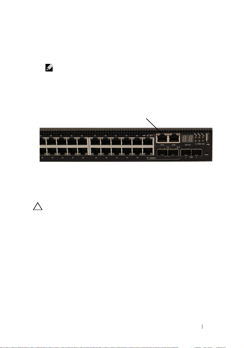
N30xx Series Front Panel
Combo
Ports
10/100/1000BASE-T Auto-sensing
Full Duplex RJ-45 Ports
SFP+
Ports
10/100/1000BASE-T Auto-sensing
Full Duplex RJ-45 Ports
Combo
Ports
SFP+
Ports
The following images show the front panels of the switch models in the
N30xx Series.
In addition to the switch ports, the front panel of each model in the N30xx
series includes the following ports:
• Console port
• USB port
• Out-of-band (OOB) management port
Figure 1-12. N3024F with 24 10/100/1000BASE-T Ports (Front Panel)
The N30xx series switch includes two combo ports. The combo ports are SFP
on the N30xx series and 1000BaseT on the N3024F switch.
Figure 1-13. N3048 with 48 10/100/1000BASE-T Ports (Front Panel)
The additional ports are on the right side of the front panel, as shown in
Figure 1-13 and Figure 1-14 on page 33.
32 Getting Started Guide
Page 35

Figure 1-14. Additional N30xx Series Ports
Combo Ports
Reset Button
USB Port
Console Port Out-of-Band Management Port
SFP+ Ports
The N30xx front panel above also contains a reset button (pinhole) and
several status LEDs. See Figure 1-14.
Figure 1-15. N30xx Close-up
The N30xx/N3024F/N30xxP front panel in Figure 1-15 displays status LEDs
for over-temperature alarm, internal power supply 1 and switch status on the
top row. The bottom row of status LEDs displays stack master, internal power
supply 2 and fan alarm.
Getting Started Guide 33
Page 36

Switch Ports
The N3024/N3024P front panel provides 24 Gigabit Ethernet
(10/100/1000BASE-T) RJ-45 ports that support auto-negotiation for speed,
flow control, and duplex. The N3024/N3024P models support two SFP+ 10G
ports. Dell-qualified SFP+ transceivers are sold separately.
The N3024F front panel provides 24 Gigabit Ethernet 100BASEFX/1000BASE-X SFP ports plus 2 1000BASE-T combo ports. Dell-qualified
SFP transceivers are sold separately.
The N3048/N3048P front panel provides 48 Gigabit Ethernet (10BASE-T,
100BASE-TX, 1000BASE-T) RJ-45 ports that support auto-negotiation for
speed, flow control, and duplex. The N3048/N3048P support two SFP+ 10G
ports. Dell-qualified SFP+ transceivers are sold separately.
The front-panel switch ports have the following characteristics:
• The switch automatically detects the difference between crossed and
straight-through cables on RJ-45 ports and automatically chooses the MDI
or MDIX configuration to match the other end.
• SFP ports support Dell-qualified transceivers.
• RJ-45 ports support full-duplex mode 10/100/1000 Mbps speeds on
standard Category 5 UTP cable.
• SFP+ ports support SFP+ transceivers and SFP+ copper twin-ax
technology plus SFP transceivers operating at 1G.
• The N3024P/N3048P front panel ports support PoE (15.4W) and PoE+
(30W).
Console Port
The console port provides serial communication capabilities, which allows
communication using RS-232 protocol. The serial port provides a direct
connection to the switch and allows access to the CLI from a console
terminal connected to the port through the provided serial cable (with RJ45
YOST to female DB-9 connectors).
The console port is separately configurable and can be run as an asynchronous
link from 1200 baud to 115,200 baud.
The Dell CLI only supports changing the speed.
34 Getting Started Guide
Page 37

The defaults are 9600 baud rate, 8 data bits, No Parity, 1 Stop Bit, No Flow
Control.
Out-of-Band Management Port
The Out-of-Band (OOB) management port is a 10/100/1000BASE-T
Ethernet port dedicated to remote switch management. Traffic on this port is
segregated from operational network traffic on the switch ports and cannot be
switched or routed to or from the operational network.
USB Port
The Type-A, female USB port supports a USB 2.0-compliant flash memory
drive. The Dell Networking switch can read or write to a flash drive formatted
as FAT-32. You can use a USB flash drive to copy switch configuration files
and images between the USB flash drive and the switch. You can also use the
USB flash drive to move and copy configuration files and images from one
switch to other switches in the network.
The USB port does not support any other type of USB device.
Reset Button
The reset button is accessed through the pinhole and allows you to perform a
hard reset on the switch. To use the reset button, insert an unbent paper clip
or similar tool into the pinhole. When the switch completes the boot process
after the reset, it resumes operation with the most recently saved
configuration. Any changes made to the running configuration that were not
saved to the startup configuration prior to the reset are lost.
Port and System LEDs
The front panel contains light emitting diodes (LEDs) that indicate the
status of port links, power supplies, fans, stacking, and the overall system
status.
For information about the status that the LEDs indicate, see the User’s
Configuration Guide.
Getting Started Guide 35
Page 38

Stack Master LED and Stack Number Display
Dual 10G Slots for SFP+, 10GBASE-T,
or Stacking/10GbE Modules
AC Power
Receptacle
Fan Vents
When a switch within a stack is the master unit, the stack master LED, which
is labeled M, is solid green. If the M LED is off, the stack member is not the
master unit. The Stack No. panel displays the unit number for the stack
member. If a switch is not part of a stack (in other words, it is a stack of one
switch), the M LED is illuminated, and the unit number is displayed.
N30xx Series Back Panel
The following images show the back panels of the N30xx switches.
Figure 1-16. N30xx Back Panel
Figure 1-17. N3024P/N3048P Back Panel
36 Getting Started Guide
Page 39
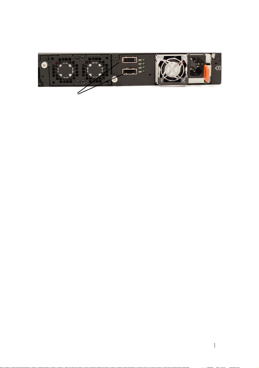
Figure 1-18. N3048 Mini-SAS Stacking Ports Close-up
Mini-SAS stacking ports
The term mini-SAS refers to the stacking port cable connections shown in
Figure 1-18. See Stacking Multiple N30xx Switches for information on using
the mini-SAS ports to connect switches.
Expansion Slots for Plug-in Modules
One expansion slot is located on the back of the N30xx models and can
support the following modules:
• 10GBASE-T module
• SFP+ module
Each plug-in module has two ports. The plug-in modules include hot-swap
support, so you do not need to reboot the switch after you install a new
module.
Getting Started Guide 37
Page 40

Power Supplies
N3024, N3024F and N3048
N3024, N3024F and N3048 switches support two 200-watt Field Replaceable
Unit (FRU) power supplies which give full power redundancy for the switch.
The N3024, N3024F and N3048 switches offer the V-lock feature for users
desiring the need to eliminate accidental power disconnection. The V-lock
receptacle on the
that has the V-lock feature to create an integral secure locking connection.
N3024P and N3048P
Dell Networking N3024P and N3048P switches support one or two 1100-watt
FRU power supplies. The N3024P switch comes with a single 715-watt power
supply (the default configuration), and supports either one or two 1100-watt
supplies. For the N3048P switch, an 1100-watt power supply is the default
configuration.
A single 1100-watt power supply can feed up to 24 PoE devices at full PoE+
power (950W). Dual-equipped switches will feed up to 48 PoE devices at full
PoE+ power (1800W), as well as provide power supply redundancy.
NOTE: PoE power is dynamically allocated. Not all ports will require the full PoE+
power.
Power Supply Unit (
PSU) allows for the use of a power cord
CAUTION: Remove the power cable from the power supplies prior to removing
the power supply module itself. Power must not be connected prior to insertion in
the chassis.
Ventilation System
Two fans cool the N30xx switches. The N30xx switches additionally have a
fan in each internal power supply. The N30xx fan is a FRU.
38 Getting Started Guide
Page 41

N30xx Model Summary
Table 1-2. N30xx Model Summary
Marketing
Model
Name
N3024 24x1G/2x1G combo/2x10G
N3024F 24x1G SFP/2x1G
N3024P 24x1G/2x1G combo/2x10G
N3048 48x1G/2x1G combo/2x10G
N3048P 48x1G/2x1G combo/2x10G
Description Power Supply
SFP+/2x Stacking/ 1x
Modular Bay/N+1
Redundant Pluggable Power
Supply Units (PSUs)/1x
Removable Fan Module
combo/2x10G SFP+/2x
Stacking/ 1x Modular
Bay/N+1 Redundant
Pluggable PSUs/1x
Removable Fan Module
SFP+/2x Stacking/ 1x
Modular Bay/N+1
Redundant Pluggable
PSUs/24x PoE+ ports/12
UPoE Capable Ports/1x
Removable Fan Module
SFP+/2x Stacking/ 1x
Modular Bay/N+1
Redundant Pluggable
PSUs/1x Removable Fan
Module
SFP+/2x Stacking/ 1x
Modular Bay/N+1
Redundant Pluggable
PSUs/48x PoE+ ports/12
UPoE Capable Ports/1x
Removable Fan Module
Regulatory
Unit
200W E07W E07W001
200W E07W E07W003
1100W/715W E06W E06W001
200W E07W E07W002
1100W/715W E06W E06C002
Model Number
Regulatory
Type
Number
Getting Started Guide 39
Page 42

N30xx Series Installation
Site Preparation
N30xx Series switches can be mounted in a standard 48.26 cm (19-inch) rack
or placed on a flat surface.
Make sure that the chosen installation location meets the following site
requirements:
•
Power
— The switch is installed near an easily accessible 100–240 VAC,
50–60 Hz outlet.
•
Clearance
access. Allow clearance for cabling, power connections, and ventilation.
•
Cabling
as radio transmitters, broadcast amplifiers, power lines, and fluorescent
lighting fixtures.
•
Ambient Temperature
range is 0 to 45ºC (32 to 113ºF) at a relative humidity of up to 95 percent,
non-condensing.
NOTE: Decrease the maximum temperature by 1°C (1.8°F) per 300 m (985 ft.) above
•
Relative Humidity
(noncondensing) with a maximum humidity gradation of 10% per hour.
— There is adequate front and rear clearance for operator
— The cabling is routed to avoid sources of electrical noise such
— The ambient switch operating temperature
900m (2955 ft.).
— The operating relative humidity is 8% to 85%
40 Getting Started Guide
Page 43

Unpacking the N30xx Switch
Package Contents
When unpacking each switch, make sure that the following items are
included:
• One Dell Networking switch
• One RJ-45 to DB-9 female cable
• One ReadyRail kit for rack installation, two mounting brackets, bolts, and
cage nuts
• One set of self-adhesive rubber pads for the free-standing switch (four pads
are included)
•One PSU
Unpacking Steps
NOTE: Before unpacking the switch, inspect the container and immediately report
any evidence of damage.
1
Place the container on a clean, flat surface and cut all straps securing the
container.
2
Open the container or remove the container top.
3
Carefully remove the switch from the container and place it on a secure
and clean surface.
4
Remove all packing material.
5
Inspect the product and accessories for damage.
Getting Started Guide 41
Page 44

Rack Mounting a N30xx Switch
You may either place the switch on the rack shelf or mount the switch directly
into a 19" wide, EIA-310-E compliant rack (four-post, two-post, or threaded
methods). The Dell ReadyRail system is provided for 1U front-rack, and twopost installations. The ReadyRail system includes two separately packaged rail
assemblies.
WARNING: This is a condensed reference. Read the safety instructions in your
Safety, Environmental, and Regulatory information booklet before you begin.
NOTE: The illustrations in this document are not intended to represent a specific
switch.
Rack Mounting Safety Considerations
• Rack loading—Overloading or uneven loading of racks may result in shelf
or rack failure, causing damage to equipment and possible personal injury.
Stabilize racks in a permanent location before loading begins. Mount
components beginning at the bottom of the rack, then work to the top. Do
not exceed your rack load rating.
• Power considerations—Connect only to the power source specified on the
unit. When multiple electrical components are installed in a rack, ensure
that the total component power ratings do not exceed circuit capabilities.
Overloaded power sources and extension cords present fire and shock
hazards.
• Elevated ambient temperature—If installed in a closed rack assembly, the
operating temperature of the rack environment may be greater than room
ambient. Use care not to exceed the 45 degrees C maximum ambient
temperature of the switch.
• Reduced air flow—Install the equipment in the rack so that the amount of
airflow required for safe operation of the equipment is not compromised.
• Reliable earthing—Maintain reliable earthing of rack-mounted
equipment. Pay particular attention to supply connections other than
direct connections to the branch circuit, for example: use of power strips.
• Product should not be mounted with the rear panel facing in the
downward position.
42 Getting Started Guide
Page 45

Installing the Dell ReadyRail System
The ReadyRail rack mounting system is provided to easily configure your rack
for installation of your switch. The ReadyRail system can be installed using
the 1U tool-less method or one of three possible 1U tooled methods (twopost flush mount, two-post center mount, or four-post threaded).
1U Tool-less Configuration (Four-post Square Hole or Unthreaded Round Hole)
1
With the ReadyRail flange ears facing outward, place one rail between the
left and right vertical posts. Align and seat the rear flange rail pegs in the
rear vertical post flange. In Figure 1-19, item 1 and its extractions illustrate
how the pegs appear in both the square and unthreaded round holes.
Figure 1-19. 1U Tool-less Configuration
2
Align and seat the front flange pegs in the holes on the front side of the
vertical post. See Figure 1-19, item 2.
3
Repeat this procedure for the second rail.
4
To remove each rail, pull on the latch release button on each flange ear and
unseat each rail. See Figure 1-19, item 3.
Getting Started Guide 43
Page 46

Two-post Flush-mount Configuration
1
For this configuration, the castings must be removed from the front side of
each ReadyRail assembly. See Figure 1-20, item 1 on page 44. Use a Torx
driver to remove the two screws from each front flange ear (on the switch
side of the rail) and remove each casting. Retain the castings for future
rack requirements. It is not necessary to remove the rear flange castings.
Figure 1-20. Two-post Flush-mount Configuration
2
Attach one rail to the front post flange with two user-supplied screws. See
Figure 1-20, item 2.
44 Getting Started Guide
Page 47

3
Slide the plunger bracket forward against the vertical post and secure the
plunger bracket to the post flange with two user-supplied screws. See
Figure 1-20, item 3.
4
Repeat this procedure for the second rail.
Two-post Center-mount Configuration
1
Slide the plunger bracket rearward until it clicks into place and secure the
bracket to the front post flange with two user-supplied screws. See
Figure 1-21, item 1.
Figure 1-21. Two-post Center-mount Configuration
2
Slide the back bracket towards the post and secure it to the post flange
with two user-supplied screws. See Figure 1-21, item 2.
3
Repeat this procedure for the second rail.
Getting Started Guide 45
Page 48

Four-post Threaded Configuration
1
For this configuration, the flange ear castings must be removed from each
end of the ReadyRail assemblies. Use a Torx driver to remove the two
screws from each flange ear and remove each casting. See Figure 1-22, item
1. Retain the castings for future rack requirements.
2
For each rail, attach the front and rear flanges to the post flanges with two
user-supplied screws at each end. See Figure 1-22, item 2.
Figure 1-22. Four-post Threaded Configuration
46 Getting Started Guide
Page 49

Installing as a Free-standing Switch
NOTE: We strongly recommend mounting the switch in a rack.
Install the switch on a flat surface if you are not installing it in a rack. The
surface must be able to support the weight of the switch and the switch
cables. The switch is supplied with four self-adhesive rubber pads.
1
Attach the self-adhesive rubber pads on each location marked on the
bottom of the switch.
2
Set the switch on a flat surface, and make sure that it has proper
ventilation by leaving 5 cm (2 inches) on each side and 13 cm (5 inches) at
the back.
Stacking Multiple N30xx Switches
You can stack N30xx switches up to 12 switches high using the mini-SAS
ports located on the rear of the switch. N30xx switches only support stacking
with other N30xx switches. When multiple switches are connected together
through the stack ports, they operate as a single unit with up to 576 front
panel ports. The stack operates and is managed as a single entity.
NOTE: If you are installing a stack of switches, you need to assemble and cable the
stack before powering up and configuring it. When a stack is powered up for the
first time, the switches elect a Master Switch, which may occupy any location in
the stack. The Master LED on the front panel is illuminated on the master unit.
Creating a Switch Stack
Create a stack by connecting adjacent units using the mini-SAS stacking
ports on the back panel of the switch. Figure 1-23 on page 48 shows the
switches connected in a ring topology, which is the recommended topology
for a stack.
1
Connect one of the mini-SAS cables into either of the stacking ports of the
top switch and the switch directly below it.
If necessary, use a separately purchased, longer (1 meter or 3 meter) miniSAS cable to connect the switches.
2
Repeat this process until all of the devices are connected.
3
Use the remaining stacking cable to connect the two remaining stacking
ports together so that a ring topology is assembled.
Getting Started Guide 47
Page 50

Figure 1-23. Connecting a Stack of Switches
Unit 1
Unit 2
Unit 3
The stack in Figure 1-23 is connected in a ring topology and has the following
physical connections between the switches:
• The bottom mini-SAS port on Unit 1 is connected to the top mini-SAS
port on Unit 2.
• The bottom mini-SAS port on Unit 2 is connected to the top mini-SAS
port on Unit 3.
• The bottom mini-SAS port on Unit 3 is connected to the top mini-SAS
port on Unit 1.
Stacking Standby
The stacking feature supports a Standby or backup unit that assumes the
Master unit role if the Master unit in the stack fails. As soon as a Master
failure is detected in the stack, the Standby unit initializes the control plane
and enables all other stack units with the current configuration. The Standby
unit maintains a synchronized copy of the running configuration for the
stack. The Standby unit is automatically selected in the stack; however, you
can use the CLI to select a different stack member as Standby. See the User’s
Configuration Guide or the CLI Reference Guide for more information.
48 Getting Started Guide
Page 51

Starting and Configuring the N30xx Switch
The flow chart in Figure 1-24 provides an overview of the steps you use to
perform the initial configuration after the switch is unpacked and mounted.
Figure 1-24. Installation and Configuration Flow Chart
Getting Started Guide 49
Page 52

Connecting a N30xx Switch to a Terminal
After completing all external connections, connect a terminal to a switch to
configure the switch.
NOTE: Read the Release Notes for this product before proceeding. You can
download the Release Notes from the Dell Support website at
dell.com/support/manuals.
NOTE: We recommend that you obtain the most recent version of the user
documentation from the Dell Support website at dell.com/support/manuals.
To monitor and configure the switch via serial console, use the console port
on the front panel of the switch (see Figure 1-25 on page 51) to connect it to
a VT100 terminal or to a computer running VT100 terminal emulation
software. The console port is implemented as a data terminal equipment
(DTE) connector.
The following equipment is required to use the console port:
• VT100-compatible terminal or a computer with a serial port running
VT100 terminal emulation software,
• A serial cable (provided) with an RJ-45 connector for the console port and
DB-9 connector for the terminal.
Perform the following tasks to connect a terminal to the switch console port:
1
Connect the DB-9 connector on the serial cable to the terminal or
computer running VT100 terminal emulation software.
2
Configure the terminal emulation software as follows:
g
Select the appropriate serial port (for example, COM 1) to connect to
the console.
h
Set the data rate to 9600 baud.
i
Set the data format to 8 data bits, 1 stop bit, and no parity.
j
Set the flow control to none.
k
Set the terminal emulation mode to
l
Select Terminal keys for Function, Arrow, and Ctrl keys. Make sure
that the setting is for Terminal keys (not Microsoft Windows keys).
such as Microsoft HyperTerminal.
VT100
.
50 Getting Started Guide
Page 53
3
Console Port
Connect the RJ-45 connector on the cable directly to the switch console
port. The Dell Networking console port is located on the right side of the
front panel and is labeled with a
NOTE: Serial console access to the stack manager is available from any
serial port via the local CLI. Only one serial console session at a time is
supported.
Figure 1-25. N3048 Console Port Location
|O|O|
symbol, as shown in Figure 1-25.
The RJ-45 port to the right of the console port is for out-of-band Ethernet
management.
Connecting a N30xx Switch to a Power Source
CAUTION: Read the safety information in the Safety and Regulatory Information
manual as well as the safety information for other switches that connect to or
support the switch.
The N30xx switches have two FRU power supplies for redundant or loadsharing operation.
AC and DC Power Connection
1
Make sure that the switch console port is connected to a VT100 terminal
or VT100 terminal emulator via the RJ-45 to DB-9 female cable.
2
Using a 5-foot (1.5 m) standard power cable with safety ground connected,
connect the power cable to the AC main receptacle located on the back
panel (see Figure 1-26 on page 52).
3
Connect the power cable to a grounded AC outlet.
Getting Started Guide 51
Page 54

Figure 1-26. Two Redundant Power Supplies on N3048 Switch
To AC Power Source
Booting the N30xx Switch
When the power is turned on with the local terminal already connected, the
switch goes through a power-on self-test (POST). POST runs every time the
switch is initialized and checks hardware components to determine if the
switch is fully operational before completely booting. If POST detects a
critical problem, the program flow stops. If POST passes successfully, valid
firmware is loaded into RAM. POST messages are displayed on the terminal
and indicate test success or failure. The boot process runs for approximately
60 seconds.
You can invoke the Boot menu after the first part of the POST is completed.
From the Boot menu, you can perform configuration tasks such as resetting
the system to factory defaults, activating the backup image, or recovering a
password. For more information about the Boot menu functions, see the CLI
Reference Guide.
52 Getting Started Guide
Page 55

Performing the N30xx Initial Configuration
The initial configuration procedure is based on the following assumptions:
• The Dell Networking switch was never configured before.
• The Dell Networking switch booted successfully.
• The console connection was established, and the
prompt appears on the screen of a VT100 terminal or terminal equivalent.
The initial switch configuration is performed through the console port. After
the initial configuration, you can manage the switch from the alreadyconnected console port or remotely through an interface defined during the
initial configuration.
NOTE: The switch is not configured with a default user name or password. The
default IP address is set to DHCP for the out-of-band
Before setting up the initial configuration of the switch, obtain the following
information from your network administrator:
• The IP address to be assigned to the management interface.
• The IP subnet mask for the network.
• The IP address of the management interface default gateway.
These settings are necessary to allow the remote management of the switch
through Telnet (Telnet client) or HTTP (Web browser).
Enabling Remote Management
The N30xx switch’s front panel contains a Gigabit Ethernet port for OOB
management. The OOB port is located to the right of the console port. On
the N30xx switches, you can use the OOB port or any of the switch ports on
the front panel for in-band management. By default, all in-band ports are
members of VLAN 1.
The Dell Easy Setup Wizard includes prompts to configure network
information for the OOB management interface on the N30xx switch and the
VLAN 1 interface on the N30xx switches. For either management interface,
you can assign a static IP address and subnet mask or enable DHCP and allow
a network DHCP server to assign the information.
See the CLI Reference Guide for information about the CLI commands you
use to configure network information.
Dell Easy Setup Wizard
(OOB) port.
Getting Started Guide 53
Page 56

Initial Configuration Procedure
You can perform the initial configuration by using the Dell Easy Setup
Wizard or by using the CLI. The wizard automatically starts when the switch
configuration file is empty. You can exit the wizard at any point by entering
[ctrl+z], but all configuration settings specified will be discarded, and the
switch will use the default values.
NOTE: If you do not run the Dell Easy Setup Wizard or do not respond to the initial
Easy Setup Wizard prompt within 60 seconds, the switch enters CLI mode. You must
reset the switch with an empty startup configuration in order to rerun the Dell Easy
Setup Wizard.
For more information about performing the initial configuration by using the
CLI, see the CLI Reference Guide. This Getting Started Guide shows how to
use the Dell Easy Setup Wizard for initial switch configuration. The wizard
sets up the following configuration on the switch:
• Establishes the initial privileged user account with a valid password. The
wizard configures one privileged user account during the setup.
• Enables CLI login and HTTP access to use the local authentication setting
only.
• Sets up the IP address for the OOB management interface.
• Sets up the IP address for the VLAN 1 routing interface, of which all
in-band ports are members.
• Sets up the SNMP community string to be used by the SNMP manager at
a given IP address. You may choose to skip this step if SNMP management
is not used for this switch.
• Allows you to specify the network management system IP address or
permit management access from all IP addresses.
• Configures the default gateway IP address for the VLAN 1 interface.
54 Getting Started Guide
Page 57

Example Session
This section describes a Dell Easy Setup Wizard session. The following
values are used by the example session:
• The SNMP community string to be used is
• The network management system (NMS) IP address is
• The user name is
admin
, and the password is
• The OOB management interface uses
• The IP address for the VLAN 1 routing interface is
subnet mask of
255.255.255.0
• The default gateway is
10.1.1.1
.
The setup wizard configures the initial values as defined above. After
completing the wizard, the switch is configured as follows:
• SNMPv2 is enabled and the community string is set up as defined above.
SNMPv3 is disabled by default.
• The admin user account is set up as defined.
• A network management system is configured. From the management
station, you can access the SNMP, HTTP, and CLI interfaces. You may also
choose to allow all IP addresses to access these management interfaces by
choosing the (0.0.0.0) IP address.
• DHCP is enabled on the OOB management interface.
• An IP address is configured for the VLAN 1 routing interface.
• A default gateway address is configured.
public
.
10.1.2.100
admin123
DHCP
for IP address assignment.
.
10.1.1.200
.
with a
NOTE: In the example below, the possible user options or default values are
enclosed in [ ]. If you press <Enter> with no options defined, the default value is
accepted. Help text is in parentheses.
Getting Started Guide 55
Page 58

Dell Easy Setup Wizard Console Example
The following example contains the sequence of prompts and responses
associated with running an example Dell Easy Setup Wizard session, using
the input values listed above.
After the switch completes the POST and is booted, the following dialog
appears:
Unit 1 - Waiting to select management unit)>
Applying Global configuration, please wait...
Welcome to Dell Easy Setup Wizard
The Setup Wizard guides you through the initial switch
configuration, and gets you up and running as quickly
as possible. You can skip the setup wizard, and enter
CLI mode to manually configure the switch. You must
respond to the next question to run the setup wizard
within 60 seconds, otherwise the system will continue
with normal operation using the default system
configuration. Note: You can exit the setup wizard at
any point by entering [ctrl+z].
Would you like to run the setup wizard (you must
answer this question within 60 seconds)? [Y/N] y
Step 1:
The system is not set up for SNMP management by
default. To manage the switch using SNMP (required for
Dell Network Manager) you can
. Set up the initial SNMP version 2 account now.
. Return later and set up other SNMP accounts. (For
more information on setting up an SNMP version 1 or
3 account, see the user documentation).
Would you like to set up the SNMP management interface
now? [Y/N] y
To set up the SNMP management account you must specify
the management system IP address and the “community
string” or password that the particular management
system uses to access the switch. The wizard
56 Getting Started Guide
Page 59

automatically assigns the highest access level
[Privilege Level 15] to this account. You can use Dell
Network Manager or other management interfaces to
change this setting, and to add additional management
system information later. For more information on
adding management systems, see the user documentation.
To add a management station:
Please enter the SNMP community string to be used.
[public]: public
NOTE: If it is configured, the default access level is set to the highest available
access for the SNMP management interface. Initially only SNMPv2 will be
activated. SNMPv3 is disabled until you return to configure security access for
SNMPv3 (e.g. engine ID, view, etc.).
Please enter the IP address of the Management System
(A.B.C.D) or wildcard (0.0.0.0) to manage from any
Management Station. [0.0.0.0]: 10.1.2.100
Step 2:
Now we need to set up your initial privilege (Level
15) user account. This account is used to login to the
CLI and Web interface. You may set up other accounts
and change privilege levels later. For more
information on setting up user accounts and changing
privilege levels, see the user documentation.
To set up a user account:
Please enter the user name. [root]:admin
Please enter the user password: ********
Please reenter the user password: ********
Step 3:
Next, IP addresses are set up on the OOB (Out-Of-Band)
Interface and/or the VLAN 1 routing interface.
You can use these IP addresses to access the CLI, Web
interface, or SNMP interface of the switch.
Getting Started Guide 57
Page 60

To access the switch through any Management Interface
you can
. Set up the IP address for the Management Interface.
. Set up the default gateway if IP address is
manually configured on both routing and OOB interface.
Would you like to set up the Out-Of-Band interface
now? [Y/N] y
Please enter the IP address of the device (A.B.C.D) or
enter “DHCP” (without the quotes) to automatically
request an IP address from the network DHCP server.
[DHCP]: dhcp
Step 4:
Would you like to set up the VLAN1 routing interface
now? [Y/N] y
Please enter the IP address of the device (A.B.C.D) or
enter “DHCP” (without the quotes) to automatically
request an IP address from the network DHCP server:
10.1.1.200
Please enter the IP subnet mask (A.B.C.D or /nn):
255.255.255.0
Step 5:
Finally, set up the default gateway. Please enter the
IP address of the gateway from which this network is
reachable. [0.0.0.0]: 10.1.1.1
This is the configuration information that has been
collected:
SNMP Interface = “public”@10.1.2.100
User Account setup = admin
Password = ********
Out-of-band IP address = DHCP
VLAN1 Router Interface IP = 10.1.1.200 255.255.255.0
Default Gateway = 10.1.1.1
58 Getting Started Guide
Page 61

Step 6:
If the information is correct, please enter (Y) to
save the configuration and copy the settings to the
start-up configuration file. If the information is
incorrect, enter (N) to discard the configuration and
restart the wizard: [Y/N] y
Thank you for using the Dell Easy Setup Wizard. You
will now enter CLI mode.
Applying Interface configuration, please wait...
Next Steps
After completing the initial configuration described in this section, you can
connect the OOB port to your management network for out-of-band remote
management, or you can connect any of the front-panel switch ports to your
production network for in-band remote management.
If you specified DHCP for the OOB or VLAN 1 management interface IP
address, the interface will acquire its IP address from a DHCP server on the
network. To discover the dynamically-assigned IP address, use the console
port connection to issue the following commands:
• For the OOB interface, enter
• For the VLAN 1 routing interface, enter
To access the Dell OpenManage Switch Administrator interface, enter the
OOB management interface IP address into the address field of a Web
browser. For remote management access to the CLI, enter the VLAN 1
management interface IP address into a Telnet or SSH client. Alternatively,
you can continue to use the console port for local CLI access to the switch.
Your N30xx switch supports basic switching features such as VLANs and
spanning tree protocol. The N30xx switches also support advanced Layer 3
features such as dynamic routing and multicast. Use the Web-based
management interface or the CLI to configure the features your network
requires. For information about how to configure the switch features, see the
User’s Configuration Guide or CLI Reference Guide available on the support
site: dell.com/support/manuals.
show ip interface out-of-band
show ip interface
.
.
Getting Started Guide 59
Page 62

60 Getting Started Guide
Page 63

Commutateur de série
N20xx/N30xx Dell
Guide de mise en route
Modèles réglementaires : N2024, N2024P,
N2048, N2048P, N3024, N3024P, N3048,
N3048P, N3024F
Page 64

Remarques, précautions et avertissements
REMARQUE : Une REMARQUE indique des informations importantes qui peuvent
vous aider à mieux utiliser votre commutateur.
PRÉCAUTION : Une PRÉCAUTION vous avertit d'un risque de dommage matériel
ou de perte de données et vous indique comment éviter le problème.
AVERTISSEMENT : UN AVERTISSEMENT indique un risque potentiel
d'endommagement du matériel, de blessure corporelle ou de mort.
____________________
© 2013 Dell Inc.
®
Marques utilisées dans ce document : Dell
marques commerciales de Dell Inc. Microsoft
Corporation aux Etats-Unis et/ou dans d'autres pays.
, le logo DELL, OpenManage™ et ReadyRails™ sont des
®
, et Windows® sont des marques déposées de Microsoft
Modèle réglementaire N2024, N2024P, N2048, N2048P, N3024, N3024P, N3048, N3048P, N3024F
Décembre 2013 P/N F5CWH Rév. A00
Page 65

Tables des matières
1 Introduction . . . . . . . . . . . . . . . . . . . . . . . 67
2 Présentation de la série N20xx
3 Présentation du matériel
de la série N20xx
Panneau avant de la série N20xx . . . . . . . . . . . . 68
Ports de commutateur
Port de console
Port USB
Bouton Reset (Réinitialisation)
Voyants des ports et du système
Voyant maître de la pile et affichage
du numéro de la pile
Panneau arrière de la série N20xx
Les blocs d'alimentation
Système de ventilation
Récapitulatif des modèles N20xx
. . . . . . . . . . . . . . . . . . 68
. . . . . . . . . . . . . . . 70
. . . . . . . . . . . . . . . . . . . 70
. . . . . . . . . . . . . . . . . . . . . . 71
. . . . . . . . . . . 71
. . . . . . . . . . 71
. . . . . . . . . . . . . . . . 72
. . . . . . . . . . . 73
. . . . . . . . . . . . . . 74
. . . . . . . . . . . . . . . 74
. . . . . . . . . . . . 75
. . . . . . . . 67
Tables des matières 63
Page 66

4 Installation de la série N20xx . . . . . . . . 75
Préparation du site. . . . . . . . . . . . . . . . . . . . 75
Déballage du commutateur N20xx
Contenu du carton
Étapes du déballage
. . . . . . . . . . . . . . . . . 77
. . . . . . . . . . . . . . . . 77
Montage en rack d'un commutateur N20xx
Montage en rack
. . . . . . . . . . . . . . . . . . 78
Installation d'un commutateur autonome
Empilage de plusieurs commutateurs N20xx
Création d'une pile de commutateurs
5 Démarrage et configuration
du commutateur N20xx
Connexion du commutateur N20xx à un terminal. . . . 83
Connexion d'un commutateur N20xx
à une source d'alimentation
Connexion des câbles d'alimentation
en CA et en CC
Démarrage du commutateur N20xx
. . . . . . . . . . . . . . . . . . . 84
. . . . . . . . . . . . . . 81
. . . . . . . . . . . . . . . 84
. . . . . . . . . . . 77
. . . . . . . 77
. . . . . 79
. . . . . . 79
. . . . . . . 79
. . . . . . . . . . . 85
Réalisation de la configuration initiale N20xx
Activation de la gestion à distance
Procédure de configuration initiale
Exemple de session
Exemple console de l'Assistant
Dell Easy Setup
Prochaines étapes
64 Tables des matières
. . . . . 86
. . . . . . . . . 86
. . . . . . . . . 87
. . . . . . . . . . . . . . . . . 88
. . . . . . . . . . . . . . . . . . . 89
. . . . . . . . . . . . . . . . . 94
Page 67

6 Présentation de la série N30xx . . . . . . . . 96
7 Présentation du matériel
de la série N30xx
N30xxPanneau avant de la série . . . . . . . . . . . . 97
Ports de commutateur
Port de console
Port de gestion hors bande
Port USB
Bouton Reset (Réinitialisation)
Voyants des ports et du système
Voyant maître de la pile et affichage
du numéro de la pile
. . . . . . . . . . . . . . . . . . 96
. . . . . . . . . . . . . . . 99
. . . . . . . . . . . . . . . . . . . 100
. . . . . . . . . . . . . 100
. . . . . . . . . . . . . . . . . . . . . . 101
. . . . . . . . . . . 101
. . . . . . . . . . 101
. . . . . . . . . . . . . . . . 101
Panneau arrière de la série N30xx
Logements d'extension pour modules plug-in
Blocs d'alimentation
. . . . . . . . . . . . . . . . 103
Système de ventilation
Récapitulatif des modèles N30xx
. . . . . . . . . . . 102
. . . 103
. . . . . . . . . . . . . . . 104
. . . . . . . . . . . . 104
8 Installation de la série N30xx . . . . . . . . 106
Préparation du site . . . . . . . . . . . . . . . . . . . 106
Déballage du commutateur N30xx
Contenu du carton
Étapes du déballage
. . . . . . . . . . . . . . . . . 107
. . . . . . . . . . . . . . . . 107
Montage en rack d'un commutateur N30xx
Sécurité relative au montage d'un rack
Installation du système ReadyRail de Dell
Installation d'un commutateur autonome
. . . . . . . . . . . 107
. . . . . . . 108
. . . . . . 108
. . . . . 109
. . . . . 114
Tables des matières 65
Page 68

Empilage de plusieurs commutateurs N30xx . . . . . 114
Création d'une pile de commutateurs
9 Démarrage et configuration
du commutateur N30xx
Connexion du commutateur N30xx à un terminal. . . 118
Connexion d'un commutateur N30xx
à une source d'alimentation
Connexion des câbles d'alimentation
en CA et en CC
Démarrage du commutateur N30xx . . . . . . . . . . 120
. . . . . . . . . . . . . . . . . . 120
. . . . . . . . . . . . . 116
. . . . . . . . . . . . . . 119
. . . . . . 114
Réalisation de la configuration initiale N30xx
Activation de la gestion à distance
Procédure de configuration initiale
Exemple de session
. . . . . . . . . . . . . . . . 123
. . . . . . . . 121
. . . . . . . . 122
Exemple console de l'Assistant Dell Easy Setup
Prochaines étapes
. . . . . . . . . . . . . . . . 130
. . . . 121
. 124
66 Tables des matières
Page 69

Introduction
Ce document contient des informations générales sur les commutateurs de la
série N20xx/N30xxDell, ainsi que des informations relatives à l'installation et
à la configuration initiale d'un commutateur. Pour obtenir des informations
sur la configuration et le contrôle des fonctions du commutateur, reportezvous au User's Configuration Guide (Guide de configuration), disponible sur
le site du Support Dell à l'adresse dell.com/support/manuals et prenez
connaissance des dernières mises à jour concernant la documentation et le
micrologiciel.
Ce document contient les sections suivantes :
• Présentation de la série N20xx
• Présentation du matériel de la série N20xx
• Installation de la série N20xx
• Démarrage et configuration du commutateur N20xx
• Présentation de la série N30xx
• Présentation du matériel de la série N30xx
• Installation de la série N30xx
• Démarrage et configuration du commutateur N30xx
• Informations NOM (Mexique uniquement)
REMARQUE : Nous conseillons fortement aux administrateurs de commutateur de
s'assurer que les commutateurs de mise en réseau Dell disposent de la dernière
version de Dell Networking Operating System (DNOS). La mise en réseau Dell
améliore continuellement les fonctionnalités et les fonctions du DNOS en fonction
des commentaires des clients. Pour une infrastructure critique, impliquant la sortie
d'une partie non critique du réseau, il est recommandé de vérifier la configuration
du réseau et son fonctionnement avec la nouvelle version de DNOS.
Présentation de la série N20xx
Les commutateurs N20xx Dell sont des commutateurs Ethernet Gigabit
de couche 2 empilables et comprennent les six modèles suivants :
• Dell N2024
• Dell N2024P
• Dell N2048
• Dell N2048P
Guide de mise en route 67
Page 70

Présentation du matériel de la série
48 ports 10/100/1000 BASE-T
Ports
SFP+
Port de console SFP+
Port USB SFP+
N20xx
Cette section contient des informations sur les caractéristiques du dispositif
et sur les configurations matérielles des modules des commutateurs de la
série N20xx.
Tous les modèles N20xx sans fonction PoE sont des commutateurs 1U
montables sur rack avec les dimensions suivantes :
• 440,0 x 257,0 x 43,5 mm (Largeur x Profondeur x Hauteur)
• 17,3 x 10,1 x 4,32 cm (Largeur x Profondeur x Hauteur)
Tous les modèles N20xx avec fonction PoE sont des commutateurs 1U
montables sur rack avec les dimensions suivantes :
• 440,0 x 387,0 x 43,5 mm (Largeur x Profondeur x Hauteur)
• 17,3 x 15,2 x 4,32 cm (Largeur x Profondeur x Hauteur)
Panneau avant de la série N20xx
Les images suivantes présentent les panneaux avant des modèles
de commutateurs de la série N20xx.
Figure 1-1. Série N2048 avec 48 ports 10/100/1000 BASE-T (Panneau avant)
En plus des ports de commutateur, le panneau avant de chaque modèle
de la série N20xx comprend les ports suivants :
• Port de console
•Port USB
68 Guide de mise en route
Page 71

Figure 1-2. N2024 Gros plan
Le panneau avant N20xx, affiché à la Figure 1-2, est équipé de voyant d'état
pour prévenir en cas de température excessive, d'alimentation interne et
d'état sur la première rangée. La deuxième rangée de voyants d'état affiche
l'état du maître de la pile, du bloc d'alimentation redondant (RPS) et l'alarme
du ventilateur.
Figure 1-3. N2024P Gros plan
Le panneau avant P N20xx, affiché à la Figure 1-3, est équipé de voyant d'état
pour prévenir en cas de température excessive, de l'état de l'alimentation
interne et de l'état sur la première rangée. La deuxième rangée de voyants
d'état affiche l'état du maître de la pile, du bloc d'alimentation modulaire
(MPS) et l'alarme du ventilateur.
Guide de mise en route 69
Page 72

Ports de commutateur
Le panneau avant N2024/N2024P est équipé de 24 ports Gigabit Ethernet
(10/100/1000BASE-T) RJ-45 qui prennent en charge la négociation
automatique de la vitesse, le contrôle du débit et le mode duplex.
Les modèles N2024/N2024P prennent en charge deux ports SFP+ 10G.
Les émetteurs-récepteurs SFP+ approuvés par Dell sont vendus séparément.
Le panneau avant N2048/N2048P est équipé de 48 ports Gigabit Ethernet
(10BASE-T, 100BASE-TX, 1000BASE-T) RJ-45 qui prennent en charge la
négociation automatique de la vitesse, le contrôle du débit et le mode duplex.
Les modèles N2048/N2048P prennent en charge deux ports SFP+ 10G.
Les émetteurs-récepteurs SFP+ approuvés par Dell sont vendus séparément.
Les ports de commutateurs du panneau avant disposent des caractéristiques
suivantes :
• Le commutateur détecte automatiquement le type de câble branché
sur les ports RJ-45 (directs ou croisés) et choisit automatiquement la
configuration MDI ou MDIX pour correspondre à l'autre extrémité.
• Les ports SFP prennent en charge les émetteurs-récepteurs SFP+
approuvés par Dell.
• Les ports RJ-45 prennent en charge les vitesses (10/100/1 000 Mpbs)
du mode duplex intégral pour un câble UTP standard de catégorie 5.
• Les ports SFP+ prennent en charge les émetteurs-récepteurs SFP+ et
les émetteurs-récepteurs SFP+ avec câble de cuivre twinax fonctionnant
à 1G.
• Les ports du panneau avant N2024P/N2048P prennent en charge la
fonction PoE (15,4 W) et PoE+ (30 W).
Port de console
Le port de console offre des capacités de communication de série qui
permettent d'effectuer des communications à l'aide du protocole RS-232.
Ce port de série offre une connexion directe au commutateur et vous permet
d'accéder à l'interface CLI depuis un terminal de console connecté au port via
le câble série fourni (RJ-45 YOST vers des connecteurs DB-9 femelles).
70 Guide de mise en route
Page 73

Le port de console est configurable séparément et peut être exécuté comme
lien asynchrone avec un débit compris entre 1 200 bauds et 115 200 bauds.
Le CLI Dell ne prend en charge que le changement de vitesse. Les valeurs par
défaut : débit de 9 600 bauds, 8 bits de données, pas de parité, 1 bit d'arrêt,
aucun contrôle de flux.
Port USB
Le port USB femelle de type A prend en charge un lecteur à mémoire flash
compatible USB 2.0. Le commutateur Dell Networking peut lire ou écrire des
données sur un lecteur flash formaté en FAT-32. Vous pouvez utiliser un
lecteur USB flash pour transférer des fichiers ou des images de configuration
entre le lecteur USB flash et le commutateur. Vous pouvez également utiliser
le lecteur flash USB pour déplacer et copier les fichiers et les images de
configuration d'un commutateur vers les autres commutateurs du réseau.
Le port USB ne prend en charge aucun autre type de périphérique USB.
Bouton Reset (Réinitialisation)
Le bouton de réinitialisation est accessible par l'intermédiaire du trou
d'épingle et vous permet d'effectuer une réinitialisation à froid du
commutateur. Pour utiliser ce bouton, insérez un trombone déplié ou un outil
similaire dans le trou d'épingle. Lorsque le commutateur a terminé le
processus de redémarrage après la réinitialisation, il reprend son
fonctionnement avec la dernière configuration enregistrée. Toute
modification apportée à la configuration en cours qui n'a pas été enregistrée
dans la configuration de démarrage avant la réinitialisation, sera perdue.
Voyants des ports et du système
Le panneau avant est équipé de voyants indiquant l'état des liaisons des ports,
des blocs d'alimentation, des ventilateurs, de l'empilement et de l'ensemble
du système.
Pour obtenir des informations sur l'état indiqué par les voyants, reportez-vous
au User's Configuration Guide (Guide de configuration).
Guide de mise en route 71
Page 74

Voyant maître de la pile et affichage du numéro de la pile
Lorsque qu'un commutateur de la pile est l'unité maître, le voyant maître
de la pile, désigné par M, est en vert fixe. Si le voyant M est éteint, le membre
de la pile n'est pas l'unité maître. Le panneau du numéro de la pile affiche
le numéro de l'unité du membre de la pile. Si un commutateur ne fait pas
partie d'une pile (en d'autres termes, il s'agit d'un pile d'un commutateur),
le voyant M est allumé et le numéro de l'unité de la pile est affiché.
72 Guide de mise en route
Page 75

Panneau arrière de la série N20xx
Ouvertures des ventilateurs
Prise d'alimentation en CA
Les images suivantes présentent les panneaux arrière des commutateurs
N20xx.
Figure 1-4. Panneau arrière N20xx
Figure 1-5. Panneau arrière N2024P/N2048P
Le terme mini-SAS reprend les connexions du câble du port d'empilage
présenté à la Figure 1-6. Reportez-vous à Empilage de plusieurs
commutateurs N20xx pour obtenir des information sur l'utilisation des ports
mini-SAS pour connecter des commutateurs.
Guide de mise en route 73
Page 76

Figure 1-6. Ventilateurs et ports d'empilage mini-SAS N2048
Ports d'empilage mini-SAS
Les blocs d'alimentation
N2024 et N2048
N2024 et N2048 les commutateurs possèdent un bloc d'alimentation interne
de 100 watts. Le bloc d'alimentation redondant supplémentaire (Dell
Networking RPS720) fournit une puissance de 180 watts et offre une pleine
redondance au commutateur.
N2024P et N2048P
les commutateurs Dell Networking N2024P et N2048P sont équipés d'un bloc
d'alimentation 1 000 Watts pouvant alimenter jusqu'à 24 périphériques PoE à
une puissance totale PoE+ (850 W). Un bloc d'alimentation externe
supplémentaire (MPS1000) offre 1 000 Watts ainsi qu'une couverture
énergétique totale pour les 48 périphériques PoE (1 800 Watts).
REMARQUE : L'alimentation PoE est allouée de manière dynamique. Tous les ports
n'ont pas besoin de l'alimentation PoE+ maximale.
PRÉCAUTION : Retirez le câble d'alimentation des blocs d'alimentation avant de
retirer le bloc d'alimentation lui-même. L'alimentation ne doit pas être connectée
avant l'insertion du bloc dans le châssis.
Système de ventilation
Deux ventilateurs refroidissent les commutateurs N20xx.
74 Guide de mise en route
Page 77

Récapitulatif des modèles N20xx
Tableau 1-1. N20xx Récapitulatif des modèles
Nom
marketing
du modèle
N2024 Empilage 24x1G/2x10G
N2024P Empilage 24x1G/2x10G
N2048 Empilage 48x1G/2x10G
N2048P Empilage 48x1G/2x10G
Description Bloc
d'alimentation
100 W E04W E04W001
SFP+/2x
1 000 W E05W E05W001
SFP+/2x/24 ports PoE
100 W E04W E04W002
SFP+/2x
1 000 W E05W E05W002
SFP+/2x/48 ports PoE
Numéro
du modèle
réglementaire
Numéro
du type
réglementaire
Installation de la série N20xx
Préparation du site
Les commutateurs de la série N20xx peuvent être montés dans un rack
standard de 19 pouces (48,26 cm) ou posés sur une surface plane.
Vérifiez que l'emplacement de l'installation choisi répond aux conditions
suivantes :
•
Alimentation
électrique facilement accessible de 100-240 VCA à 50-60 Hz.
•
Dégagement
dégagés pour rester accessibles à un opérateur. Prévoyez un dégagement
pour le câblage, les connexions électriques et la ventilation.
•
Câblage
bruit électrique, telles que les émetteurs radioélectriques, les
amplificateurs de diffusion, les lignes électriques et les luminaires pour
lampes fluorescentes.
: le commutateur doit être installé à proximité d'une prise
: l'avant et l'arrière de l'unité doivent être suffisamment
: les câbles doivent être acheminés de façon à éviter les sources de
Guide de mise en route 75
Page 78

•
Température ambiante
: la température ambiante du commutateur doit
être comprise entre 0 et 45° C (32 et 113° F), avec une humidité relative
maximale de 95 % sans condensation.
REMARQUE : Au-dessus de 900 mètres (2 955 pieds), réduisez la température
maximale d'un degré Celsius (1,8°F) par 300 mètres (985 pieds).
•
Humidité relative
: l'humidité relative de fonctionnement est comprise
entre 8 % et 85 % (sans condensation) avec une augmentation maximale
de 10 % par heure.
76 Guide de mise en route
Page 79

Déballage du commutateur N20xx
Contenu du carton
Lors du déballage de chaque commutateur, vérifiez que le carton contient
les éléments suivants :
• Un commutateur Dell Networking
• Un câble RJ-45 vers un connecteur DB-9 femelle
• Un kit de montage (N20xx) pour l'installation en rack, deux supports
de fixation, boulons et écrous à cage
• Quatre patins adhésifs en caoutchouc pour l'installation du commutateur
autonome
Étapes du déballage
REMARQUE : Avant de déballer le commutateur, examinez le carton et signalez
immédiatement tout dommage apparent.
1
Posez le carton sur une surface plane et propre et coupez toutes les sangles
d'attache.
2
Ouvrez le carton ou retirez le couvercle.
3
Retirez avec précaution le commutateur de son carton et posez-le sur
une surface propre et stable.
4
Retirez tout le matériel d'emballage.
5
Vérifiez que le produit et ses accessoires ne sont pas endommagés.
Montage en rack d'un commutateur N20xx
AVERTISSEMENT : Prenez connaissance des consignes de sécurité figurant
dans le document Safety and Regulatory Information (Informations sur la sécurité
et les réglementations), ainsi que des informations concernant la sécurité des
autres appareils connectés au commutateur.
Le connecteur d'alimentation en CA se trouve sur le panneau arrière
du commutateur.
Guide de mise en route 77
Page 80

Montage en rack
AVERTISSEMENT : N'utilisez pas les kits de montage en rack pour fixer le
commutateur sous une table ou un bureau, ni pour une installation murale.
PRÉCAUTION : Débranchez tous les câbles du commutateur avant de continuer
la procédure. Retirez tous les patins adhésifs situés sous le commutateur, le cas
échéant.
PRÉCAUTION : Si vous installez plusieurs commutateurs dans un rack,
commencez par les emplacements du bas et procédez en remontant vers le haut
du rack.
1
Placez le support de fixation du rack sur un côté du commutateur, en
alignant les orifices de montage des deux éléments. La Figure 1-7 indique
l'emplacement approprié pour le montage des supports.
Figure 1-7. Fixation des supports
2
Insérez les boulons qui vous ont été fournis dans les orifices de montage,
puis serrez-les à l'aide d'un tournevis.
3
Répétez l'opération de l'autre côté du commutateur.
4
Insérez le commutateur dans le rack de 19 pouces (48,26 cm), en veillant
à ce que ses orifices de montage soient bien alignés sur ceux du rack.
5
Fixez le commutateur dans le rack en utilisant le système de fixation
approprié à votre rack (boulons, écrous à cage ou avec rondelles).
Fixez les boulons du bas avant ceux du haut.
PRÉCAUTION : Assurez-vous que les boulons fournis correspondent aux orifices
pré-filetés du rack.
REMARQUE : Vérifiez que les entrées d'air ne sont pas obstruées.
78 Guide de mise en route
Page 81

Installation d'un commutateur autonome
REMARQUE : Nous vous recommandons fortement de monter le commutateur
dans un rack.
Si vous n'installez pas le commutateur dans un rack, posez-le sur une surface
plane. Cette surface doit pouvoir supporter le poids de l'appareil et de ses
câbles. Le commutateur est livré avec quatre patins adhésifs en caoutchouc.
1
Fixez les patins adhésifs en caoutchouc sur les emplacements marqués,
sous le commutateur.
2
Installez le commutateur sur une surface plane. Pour une ventilation
correcte, laissez un espace de 5 cm (2 pouces) de chaque côté et de 13 cm
(5 pouces) à l'arrière.
Empilage de plusieurs commutateurs N20xx
Vous pouvez empiler jusqu'à 12 commutateurs N20xx grâce aux ports miniSAS situés sur l'avant du commutateur. Les commutateurs N20xx prennent
en charge uniquement l'empilage avec d'autres commutateurs de la série
N20xx. Lorsque plusieurs commutateurs sont connectés ensemble à l'aide des
ports d'empilage, ils fonctionnent comme une seule unité avec un maximum
de 576 ports sur le panneau avant. La pile fonctionne est gérée comme une
seule entité.
REMARQUE : Si vous installez une pile de commutateurs, vous devez terminer son
montage et son câblage avant de la mettre sous tension et de la configurer.
Lorsqu'une pile est mise sous tension pour la première fois, l'un des commutateurs
est désigné comme commutateur maître de la pile. Ce commutateur peut occuper
n'importe quel emplacement. Le voyant maître situé sur le panneau avant est
allumé sur l'unité maître.
Création d'une pile de commutateurs
Créez une pile en connectant les unités adjacentes à l'aide des ports
d'empilage mini-SAS situés sur le panneau arrière du commutateur.
La Figure 1-8 à la page 80 présente les commutateurs connectés selon une
typologie en anneau, qui est la topologie recommandée pour une pile.
1
Utilisez un câble mini-SAS pour relier l'un des ports d'empilage
du commutateur situé en haut de la pile au commutateur situé juste
en-dessous.
Guide de mise en route 79
Page 82

Au besoin, utilisez un câble mini-SAS plus long (1 ou 3 mètres, non
Unité 1
Unité 2
Unité 3
fourni) pour connecter les commutateurs.
2
Répétez l'opération jusqu'à ce que toutes les unités soient connectées.
3
Utilisez le câble d'empilage restant pour connecter les deux derniers ports
d'empilage restants ensemble afin de terminer la topologie en anneau.
Figure 1-8. Connexion d'une pile de commutateurs
La pile illustrée à la Figure 1-8 est connectée selon une typologie en anneau
et présente les connexions suivantes entre les commutateurs :
• Le port mini-SAS situé en bas de l'unité 1 est connecté au port mini-SAS
de l'unité 2.
• Le port mini-SAS situé en bas de l'unité 2 est connecté au port mini-SAS
de l'unité 3.
• Le port mini-SAS situé en bas de l'unité 3 est connecté au port mini-SAS
de l'unité 1.
80 Guide de mise en route
Page 83

Unité de secours
La fonction d'empilage permet d'utiliser une unité de secours prévue pour
prendre le relais en cas de panne de l'unité maître de la pile. Dès qu'une
panne de l'unité maître de la pile est détectée, l'unité de secours initialise
la carte de contrôle et active la configuration en cours sur toutes les autres
unités de la pile. Cette unité de secours gère une copie synchronisée de la
configuration en cours pour la pile. L'unité de secours de la pile est
sélectionnée automatiquement, mais vous pouvez utiliser l'interface CLI
pour sélectionner un autre membre de la pile comme unité de secours.
Pour obtenir plus d'informations, reportez-vous au User's Configuration
Guide (Guide de configuration) ou au CLI Reference Guide (Guide de
référence CLI).
Démarrage et configuration du commutateur N20xx
L'organigramme ci-dessous présente un aperçu des étapes que vous devez
effectuer lors de la configuration initiale après avoir déballé et monté le
commutateur.
Guide de mise en route 81
Page 84

Figure 1-9. Organigramme des procédures d'installation et de configuration
Connexion de
l'alimentation
et de la console
Mise sous tension
Choix de l'option 2
Menu d'amorçage
(fonctions
spéciales)
Redémarrage
Chargement du
programme de la
mémoire flash
vers la RAM
Configuration
initiale manuelle
Assistant de
configuration Easy
Setup
Configuration
avancée
Entrer
Entrer
dans l'Assistant ?
Oui
Non
Oui
Non
dans le menu
d'amorçage ?
82 Guide de mise en route
Page 85

Connexion du commutateur N20xx à un terminal
Une fois toutes les connexions externes effectuées, connectez un terminal à
un commutateur pour configurer ce dernier.
REMARQUE : avant de continuer, lisez les notes de publication concernant ce
produit. Vous pouvez les télécharger à partir du site du Support Dell à l'adresse
dell.com/support/manuals.
REMARQUE : nous vous recommandons de vous procurer la version la plus
récente de la documentation utilisateur disponible sur le site du Support Dell à
l'adresse http://support.dell.com/manuals.
Pour pouvoir gérer et configurer le commutateur à partir d'une console série,
utilisez le port de console situé à l'avant du commutateur (voir la Figure 1-1 à
la page 68) pour le relier à un terminal VT100 ou à un système exécutant un
logiciel d'émulation de terminal VT100. Le port de console est implémenté
en tant que connecteur d'équipement de terminal de données (DTE).
Pour utiliser le port de console, vous devez disposer de l'équipement suivant :
• un terminal compatible VT100, ou un ordinateur équipé d'un port série et
exécutant un logiciel d'émulation de terminal VT100,
Microsoft HyperTerminal
;
• un câble série (fourni) doté d'un connecteur RJ-45 pour le port de console
et d'un connecteur DB-9 pour le terminal.
Pour connecter un terminal au port de console du commutateur, procédez
comme suit :
1
Reliez le connecteur DB-9 du câble série au terminal ou à l'ordinateur
exécutant le logiciel d'émulation de terminal VT100.
2
Configurez le logiciel d'émulation de terminal comme suit :
a
Sélectionnez le port série approprié (par exemple COM 1) pour vous
connecter à la console.
b
Réglez le débit de données sur 9 600 bauds.
c
Configurez le format de données sur 8 bits de données, 1 bit d'arrêt
et aucune parité.
d
Définissez le contrôle de flux sur aucun.
e
Réglez le mode d'émulation du terminal sur
par exemple,
VT100
.
Guide de mise en route 83
Page 86

f
Port de console
Choisissez les touches de terminal pour les touches de fonction,
de direction et Ctrl. Vérifiez que le paramétrage correspond bien à
Touches de terminal (et non à Touches Microsoft Windows).
3
Branchez le connecteur RJ-45 du câble directement au commutateur du
port de console. Le port de console Dell Networking est situé sur le côté
droit du panneau avant et est désigné par le symbole
indiqué sur la Figure 1-10 à la page 84.
REMARQUE : L'accès de la console de série au maître de la pile est possible
depuis n'importe quel port de série via le CLI local. Une seule session de
console de série est prise en charge à la fois.
Figure 1-10. Panneau avant N2024P avec port de console
|O|O|
, comme
Connexion d'un commutateur N20xx à une source d'alimentation
PRÉCAUTION : Prenez connaissance des consignes de sécurité figurant dans
le manuel Safety and Regulatory Information (Informations sur la sécurité et les
réglementations), ainsi que des informations concernant la sécurité des autres
appareils connectés au commutateur.
Tous les modèles N20xx sont équipés d'un bloc d'alimentation interne.
Les
prises d'alimentation se trouvent sur le panneau arrière.
Connexion des câbles d'alimentation en CA et en CC
1
Assurez-vous que le port de console du commutateur est connecté à un
terminal VT100 ou à un émulateur de terminal VT100 via le câble RJ-45
vers le câble DB-9 femelle.
2
Branchez un câble d'alimentation standard de 1,5 m (5 pieds) avec mise à
la terre à la prise CA principale, située sur le panneau arrière (voir la
Figure 1-11 à la page 85).
84 Guide de mise en route
Page 87

3
Vers une source d'alimentation en CC (facultatif)
Vers une source d'alimentation en CA
Branchez le câble d'alimentation à une prise CA avec mise à la terre.
4
Si vous utilisez un bloc d'alimentation en CC redondant ou externe
(Dell Networking RPS720 ou Dell Networking MPS1000), branchez le
câble d'alimentation en CC sur la prise correspondante, situé sur le
panneau arrière de l'appareil. Sur la Figure 1-11 à la page 85, le bloc
d'alimentation redondant se trouve au milieu et est nommé RPS.
Figure 1-11. Connexion des câbles d'alimentation en CA et en CC à un commutateur N2048
Démarrage du commutateur N20xx
À la mise sous tension, lorsque le terminal local est déjà connecté, le
commutateur effectue un auto-test de démarrage. Ce test s'exécute à chaque
initialisation du commutateur ; il passe les composants matériels en revue
pour vérifier que le commutateur est totalement opérationnel avant de
terminer le démarrage. Si le test détecte un problème critique, le processus
s'arrête. Si l'auto-test de démarrage se déroule sans incident, le micrologiciel
valide est chargé dans la RAM. Les messages de l'auto-test de démarrage sont
affichés sur le terminal et indiquent le succès ou l'échec du test. Le processus
de démarrage dure environ 60 secondes.
Vous pouvez faire appel au menu Boot (Amorçage), à la fin de la première
partie de l'auto-test de démarrage. Depuis ce menu, vous pouvez effectuer
des tâches de configuration, telles que rétablir le système sur les paramètres
d'usine par défaut, activer l'image de sauvegarde ou récupérer un mot de
passe. Pour obtenir plus d'informations sur les fonctions du menu Boot
(Amorçage), reportez-vous au CLI Reference Guide (Guide de référence CLI).
Guide de mise en route 85
Page 88

Réalisation de la configuration initiale N20xx
La procédure de configuration initiale repose sur les conditions suivantes :
• Le commutateur Dell Networking n'a jamais été configuré avant.
• Le commutateur Dell Networking a démarré correctement.
• La connexion à la console est établie et l'invite de l'
est affichée sur l'écran d'un terminal VT100 ou équivalent.
Setup
La configuration initiale du commutateur est effectuée via le port de console.
Une fois cette première étape effectuée, le commutateur peut être géré soit
à partir de la console connectée, soit à distance, via une interface définie lors
de la configuration initiale.
REMARQUE : Le commutateur ne possède pas de nom d'utilisateur, de mot
de passe, ni d'adresse IP par défaut.
Avant de procéder à la configuration initiale du commutateur, demandez
les informations suivantes à votre administrateur réseau :
• l'adresse IP à affecter à l'interface de gestion ;
• le masque de sous-réseau IP ;
• l'adresse IP correspondant à la passerelle par défaut de l'interface
de gestion.
Ces paramètres sont nécessaires pour permettre la gestion à distance
du commutateur via Telnet (client Telnet) ou HTTP (navigateur Web).
Assistant Dell Easy
Activation de la gestion à distance
Sur les commutateurs N20xx, vous pouvez utiliser n'importe quels ports
de commutateur du panneau avant pour une gestion intrabande. Par défaut,
tous les ports intrabande sont membres du VLAN 1.
L'Assistant Dell Easy Setup inclut des invites afin de configurer les
informations du réseau de l'interface VLAN 1 sur le commutateur N20xx.
Vous pouvez assigner une adresse IP statique et un masque de sous-réseau,
ou activer le protocole DHCP et permettre à un serveur réseau DHCP
d'assigner les informations.
Reportez-vous au CLI Reference Guide (Guide de référence CLI) pour
obtenir des informations sur les commandes CLI que vous utilisez pour
configurer les informations réseau.
86 Guide de mise en route
Page 89

Procédure de configuration initiale
Vous pouvez effectuer la configuration initiale à l'aide de l'interface CLI ou
de l'Assistant Dell Easy Setup. Cet assistant démarre automatiquement si
le fichier de configuration du commutateur est vide. Vous pouvez quitter
l'assistant à tout moment en appuyant sur [ctrl+z]. Dans ce cas, tous les
paramètres de configuration spécifiés sont supprimés et le commutateur
utilise les valeurs par défaut.
REMARQUE : Si vous n'exécutez pas l'Assistant Dell Easy Setup ou ne répondez
pas à l'invite de l'Assistant Easy Setup dans les 60 secondes, le commutateur entre
en mode CLI. Vous pouvez réinitialiser le commutateur avec une configuration de
démarrage vide afin d'exécuter à nouveau l'Assistant Dell Easy Setup.
Pour plus d'informations sur la configuration initiale à l'aide de l'interface
CLI, reportez-vous au CLI Reference Guide (Guide de référence CLI). Ce
Getting Started Guide (Guide de mise en route)présente la manière d'utiliser
l'Assistant Dell Easy Setup pour effectuer le configuration initiale du
commutateur. L'assistant effectue les opérations de configuration suivantes
sur le commutateur :
• Il met en place le compte utilisateur privilégié initial et lui attribue un mot
de passe valide. Un compte utilisateur privilégié est configuré par
l'assistant lors de l'installation.
• Il configure l'ouverture de session de l'interface CLI et l'accès HTTP
de sorte qu'ils utilisent uniquement l'authentification locale.
• Il configure l'adresse IP pour l'interface de routage VLAN 1, où tous
les ports intrabandes y sont membres.
• Il définit la chaîne de communauté SNMP de sorte que le gestionnaire
SNMP l'utilise sur une adresse IP donnée. Vous pouvez ignorer cette étape
si le commutateur n'est pas géré via SNMP.
• Il vous permet d'indiquer l'adresse IP du système de gestion du réseau ou
d'autoriser l'accès aux fonctions de gestion à partir de toutes les adresses IP.
• Il configure l'adresse IP de la passerelle par défaut pour l'interface VLAN 1.
Guide de mise en route 87
Page 90

Exemple de session
Cette section décrit une session Assistant Dell Easy Setup. Les valeurs
suivantes sont utilisées dans l'exemple :
• La chaîne de communauté SNMP à utiliser est
• L'adresse IP du système de gestion du réseau (NMS) est
• Le nom d'utilisateur est
admin
et le mot de passe est
• L'adresse IP pour l'interface de routage VLAN 1 est
le masque de sous-réseau est
• La passerelle par défaut est
255.255.255.0
10.1.1.1
.
L'assistant définit les valeurs initiales comme indiqué ci-dessus. Une fois
l'exécution de l'assistant terminée, le commutateur est configuré de la façon
suivante :
• SNMPv2 est activé et la chaîne de communauté est définie comme
indiqué ci-dessus. SNMPv3 est désactivé par défaut.
• Le compte utilisateur admin est configuré comme indiqué ci-dessus.
• Un système de gestion du réseau est configuré. À partir de la station
de gestion, vous pouvez accéder aux interfaces SNMP, HTTP et CLI.
Vous pouvez également décider d'autoriser toutes les adresses IP à accéder
à ces interfaces de gestion en sélectionnant l'adresse IP 0.0.0.0.
• Une adresse IP est configurée pour l'interface de routage du VLAN 1.
• Une adresse de passerelle par défaut est configurée.
.
public
10.1.1.200
.
10.1.2.100
admin123
;
.
.
REMARQUE : Dans l'exemple ci-après, les options que l'utilisateur peut
sélectionner ou les valeurs par défaut sont présentées entre crochets [ ]. Si vous
appuyez sur <Entrée> sans avoir défini d'options, la valeur par défaut est acceptée.
Le texte de l'aide se trouve entre parenthèses.
88 Guide de mise en route
Page 91

Exemple console de l'Assistant Dell Easy Setup
L'exemple suivant montre une suite d'invites et de réponses affichées dans
l'Assistant Dell Easy Setup. Les valeurs utilisées sont indiquées ci-dessus.
Au démarrage du commutateur (après l'auto-test de démarrage), la boîte
de dialogue suivante s'affiche :
Unit 1 - Waiting to select management unit)> (Unité
1 – En attente de sélection d'une unité de gestion)
Applying Global configuration, please wait ...
(Application de la configuration globale, veuillez
patienter…)
Welcome to Dell Easy Setup Wizard (Bienvenue dans
l'Assistant Dell Easy Setup)
The Setup Wizard guides you through the initial switch
configuration, and gets you up and running as quickly
as possible. (L'Assistant de configuration vous guide
au cours de la configuration initiale du commutateur
et vous permet une mise en route aussi rapide que
possible.) You can skip the setup wizard, and enter
CLI mode to manually configure the switch. (Vous
pouvez passer cet assistant et entrer en mode CLI afin
de configurer manuellement le commutateur.) You must
respond to the next question to run the setup wizard
within 60 seconds, otherwise the system will continue
with normal operation using the default system
configuration. (Vous devez répondre à la question
suivante dans les 60 secondes pour exécuter
l'Assistant de configuration, sinon le système va
utiliser la configuration système par défaut et
poursuivre son fonctionnement normal.) Note: You can
exit the setup wizard at any point by entering
[ctrl+z]. (Remarque : vous pouvez quitter l'assistant
de configuration à tout moment en appuyant sur
[ctrl+z].)
Guide de mise en route 89
Page 92

Would you like to run the setup wizard (you must
answer this question within 60 seconds)? (Souhaitezvous exécuter l'assistant de configuration [vous devez
répondre à la question dans les 60 secondes] ?) [Y/N]
y ([O/N] o)
Step 1: (Étape 6 :)
The system is not set up for SNMP management by
default. (Le système n'est pas configuré par défaut
pour la gestion SNMP.) To manage the switch using SNMP
(required for Dell Network Manager) you can (Pour
gérer le commutateur à l'aide de SNMP (requis pour
Dell Network Manager) vous pouvez)
Set up the initial SNMP version 2 account now.
(configurer le compte initial SNMP version 2
maintenant.)
Return later and set up other SNMP accounts.
(revenir plus tard et configurer d'autres comptes
SNMP.) (For more information on setting up an SNMP
version 1 or 3 account, see the user
documentation). [Pour obtenir plus d'informations sur
le paramétrage de comptes utilisant la version 1 ou 3,
reportez-vous à la documentation d'utilisation.]
Would you like to set up the SNMP management interface
now? (Souhaitez-vous configurer l'interface de
gestion SNMP immédiatement ?) [Y/N] y ([O/N] o)
To set up the SNMP management account you must specify
the management system IP address and the "community
string" or password that the particular management
system uses to access the switch. (Pour configurer le
compte de gestion SNMP, vous devez indiquer l'adresse
IP du système de gestion ainsi que la « chaîne de
communauté » ou le mot de passe que le système de
gestion utilise pour accéder au commutateur.) The
wizard automatically assigns the highest access level
[Privilege Level 15] to this account. (L'assistant
assigne automatiquement le niveau d'accès le plus
élevé [niveau de privilège 15] à ce compte.)
90 Guide de mise en route
Page 93

You can use Dell Network Manager or other management
interfaces to change this setting, and to add
additional management system later. (Vous pouvez
utiliser Dell Network Manager ou d'autres interfaces
pour modifier ce paramètre et pour ajouter des
informations système de gestion supplémentaires
ultérieurement.) For more information on adding
management systems, see the user documentation.
(Pour obtenir plus d'informations sur l'ajout de
systèmes de gestion, reportez-vous à la documentation
utilisateur.)
To add a management station: (Pour ajouter une station
de gestion :)
Please enter the SNMP community string to be used.
(Veuillez entrer la chaîne de communauté SNMP à
utiliser.) [public]: public
REMARQUE : S'il est configuré, le niveau d'accès par défaut est défini sur l'accès
maximum disponible pour l'interface de gestion SNMP. Initialement, seul SNMPv2
est activé. SNMPv3 est désactivé jusqu'à ce que vous l'activiez de manière
explicite en paramétrant l'ID du moteur, la vue, etc.
Please enter the IP address of the Management System
(A.B.C.D) or wildcard (0.0.0.0) to manage from any
Management Station. (Veuillez entrer l'adresse IP du
système de gestion (A.B.C.D) ou un masque (0.0.0.0)
pour gérer le système depuis n'importe quelle station
de gestion.) [0.0.0.0]: 10.1.2.100
Step 2: (Étape 2 :)
Now we need to set up your initial privilege (Level
15) user account. (À présent il faut configurer votre
compte utilisateur privilège initial [niveau 15].)
This account is used to login to the CLI and Web
interface. (Ce compte est utilisé pour se connecter à
l'interface CLI et à l'interface Web.) You may set up
other accounts and change privilege levels later.
(Vous pouvez configurer d'autres comptes et modifier
les niveaux de privilège ultérieurement.)
Guide de mise en route 91
Page 94

For more information on setting up user accounts and
changing privilege levels, see the user documentation.
(Pour obtenir plus d'informations sur la configuration
de comptes utilisateur et la modification des niveaux
de privilège, reportez-vous à la documentation
utilisateur.)
To set up a user account: (Pour configurer un compte
utilisateur :)
Please enter the user name. (Veuillez entrer votre nom
d'utilisateur.) [root]:admin
Please enter the user password: (Veuillez entrer votre
mot de passe :) ********
Please reenter the user password: (Veuillez confirmer
votre mot de passe :) ********
Step 3: (Étape 3 :)
Next, an IP address is set up on the VLAN 1 routing
interface. (Ensuite, une adresse IP est configurée
pour l'interface de routage VLAN 1.)
You can use the IP address to access the CLI, Web
interface, or SNMP interface of the switch. (Vous
pouvez utiliser cette adresse IP pour accéder à
l'interface CLI, à l'interface Web ou à l'interface
SNMP du commutateur.)
To access the switch through any Management Interface
you can (Pour accéder au commutateur via n'importe
quelle interface de gestion, vous pouvez)
Set up the IP address for the Management Interface.
(configurer l'adresse IP de l'interface de gestion.)
Set up the default gateway if IP address is
manually configured on the routing interface.
(configurer la passerelle par défaut si l'adresse IP
est configurée manuellement sur l'interface de
routage.)
92 Guide de mise en route
Page 95

Step 4: (Étape 4 :)
Would you like to set up the VLAN1 routing interface
now? (Souhaitez-vous configurer l'interface de
routage VLAN1 maintenant ?) [Y/N] y ([O/N] o)
Please enter the IP address of the device (A.B.C.D) or
enter "DHCP" (without the quotes) to automatically
request an IP address from the network DHCP server:
(Veuillez entrer l'adresse IP du périphérique
(A.B.C.D) ou entrer « DHCP » (sans les guillemets)
pour demander automatiquement une adresse IP depuis
le serveur réseau DHCP :) 10.1.1.200
Please enter the IP subnet mask (A.B.C.D or /nn):
(Veuillez entrer le masque de sous-réseau [A.B.C.D
ou /nn] :) 255.255.255.0
Step 5: (Étape 5 :)
Finally, set up the default gateway. (Enfin,
configurez la passerelle par défaut.) Please enter the
IP address of the gateway from which this network is
reachable. (Veuillez entrer l'adresse IP de la
passerelle à partir de laquelle ce réseau est
accessible.) [0.0.0.0]: 10.1.1.1
This is the configuration information that has been
collected: (Voici les informations de configuration
collectées :)
SNMP Interface = “public‽@10.1.2.100 (Interface
SNMP)
User Account setup = admin (Configuration compte
utilisateur)
Password = ********** (Mot de passe)
VLAN1 Router Interface IP = 10.1.1.200 255.255.255.0
(Adresse IP de l'interface de routage VLAN1)
Default Gateway = 10.1.1.1 (Passerelle par défaut)
Guide de mise en route 93
Page 96

Step 6: (Étape 6 :)
If the information is correct, please enter (Y) to
save the configuration and copy the settings to the
start-up configuration file. (Si les informations sont
correctes, veuillez saisir (Y) pour enregistrer la
configuration et copier les paramètres dans le fichier
de configuration de démarrage.) If the information is
incorrect, enter (N) to discard the configuration and
restart the wizard: (Si les informations sont
incorrectes, entrez (N) pour annuler la configuration
et redémarrer l'assistant :) [Y/N] y ([O/N] o)
Thank you for using the Dell Easy Setup Wizard. (Merci
d'avoir utilisé l'Assistant Dell Easy Setup.) You will
now enter CLI mode. (Vous allez entrer maintenant en
mode CLI.)
Applying Interface configuration, please wait...
(Application de la configuration d'interface,
veuillez patienter…)
Prochaines étapes
Une fois la configuration initiale décrite dans cette section terminée, vous
pouvez connecter n'importe quel port situé sur le panneau avant du
commutateur à votre réseau de production pour une gestion à distance
intrabande.
Si vous avez spécifié DHCP pour l'adresse IP de l'interface de gestion VLAN
1, l'interface va obtenir son adresse IP à partir d'un serveur DHCP sur le
réseau. Pour détecter une adresse IP affectée de manière dynamique, utilisez
la connexion du port de console et entrez la commande suivante :
• Pour l'interface de routage VLAN 1, tapez
l'interface IP).
Pour accéder à l'interface Dell OpenManage Switch Administrator, entrez
l'adresse IP de l'interface de gestion VLAN 1 dans le champ d'adresse d'un
navigateur Internet. Pour un accès de gestion à distance à l'interface CLI,
entrez l'adresse IP de l'interface de gestion VLAN 1 dans un client Telnet ou
SSH. Sinon, vous pouvez continuer d'utiliser le port de console pour un accès
local via l'interface CLI au commutateur.
show ip interface
(afficher
94 Guide de mise en route
Page 97

Votre commutateur N20xx prend en charge les fonctions de commutation
de base telles que les protocoles VLAN et STP. Utilisez l'interface de gestion
Web ou CLI pour configurer les fonctions requises par votre réseau. Pour
obtenir des informations sur la manière de configurer les fonctions du
commutateur, reportez-vous au User's Configuration Guide (Guide de
configuration) ou au CLI Reference Guide (Guide de référence CLI)
disponible sur le site de Support à l'adresse : dell.com/support/manuals.
Guide de mise en route 95
Page 98

Présentation de la série N30xx
Les commutateurs N30xx Dell sont des commutateurs Ethernet Gigabit
de couches 2 et 3 empilables et comprennent les modèles suivants :
• Dell N3024
• Dell N3024P
• Dell N3048
• Dell N3048P
• Dell N3024F
Présentation du matériel de lasérieN30xx
Cette section contient des informations sur les caractéristiques du dispositif
et sur les configurations matérielles des modules des commutateurs de la
série N30xx.
Tous les modèles N30xx sont des commutateurs 1U montables sur rack avec
les dimensions suivantes :
• 434,0 x 407,0 x 43,5 mm (Largeur x Profondeur x Hauteur)
• 17,1 x 16,0 x 4,32 cm (Largeur x Profondeur x Hauteur)
96 Guide de mise en route
Page 99

N30xxPanneau avant de la série
Ports
combo
Ports RJ-45 10/100/1000 BASE-T
en duplex intégral et à détection automatique
Ports
SFP+
Ports RJ-45 10/100/1000 BASE-T
en duplex intégral et à détection automatique
Ports
combo
Ports
SFP+
Les images suivantes présentent les panneaux avant des modèles de
commutateurs de la série N30xx.
En plus des ports de commutateur, le panneau avant de chaque modèle
de la série N30xx comprend les ports suivants :
• Port de console
•Port USB
• Port de gestion hors bande (OOB)
Figure 1-12. Série N3024F avec 24 ports 10/100/1000 BASE-T (Panneau avant)
Le commutateur de série N30xx comprend deux ports combo. Les ports
combo sont des ports SFP pour le commutateur de série N30xx et des ports
1000BaseT pour le commutateur de série N3024F.
Figure 1-13. Série N3048 avec 48 ports 10/100/1000 BASE-T (Panneau avant)
Guide de mise en route 97
Page 100

Les ports supplémentaires se trouvent sur le panneau avant du côté droit,
Ports combo
Bouton Reset
(Réinitialisation)
Port USB
Port de console Port de gestion hors bande
Ports SFP+
comme illustré sur la Figure 1-13 et la Figure 1-14 à la page 98.
Figure 1-14. Ports supplémentaires présents sur les commutateurs N30xx
Le panneau avant N30xx comporte également un bouton de réinitialisation
(trou d'épingle) et plusieurs voyants d'état. Voir la Figure 1-14.
98 Guide de mise en route
 Loading...