

Page 1

Migrating Exchange 2010 to Dell
Advanced Infrastructure Manager
Environment
A Dell Technical White Paper
Global Solutions Engineering Team
Feedback:
solutionfeedback@dell.com
Page 2

Migrating Exchange 2010 To Dell Advanced Infrastructure Manager Environment
THIS WHITE PAPER IS FOR INFORMATIONAL PURPOSES ONLY, AND MAY CONTAIN TYPOGRAPHICAL
ERRORS AND TECHNICAL INACCURACIES. THE CONTENT IS PROVIDED AS IS, WITHOUT EXPRESS OR
IMPLIED WARRANTIES OF ANY KIND.
© 2010 Dell Inc. All rights reserved. Reproduction of this material in any manner whatsoever without
the express written permission of Dell Inc. is strictly forbidden. For more information, contact Dell.
Dell, the DELL logo, PowerEdge, PowerConnect, PowerVault, and EqualLogic are trademarks of Dell
Inc. Symantec and the SYMANTEC logo are trademarks or registered trademarks of Symantec
Corporation or its affiliates in the US and other countries. Microsoft, Windows, Windows Server, and
Active Directory are either trademarks or registered trademarks of Microsoft Corporation in the United
States and/or other countries. Other trademarks and trade names may be used in this document to
refer to either the entities claiming the marks and names or their products. Dell Inc. disclaims any
proprietary interest in trademarks and trade names other than its own.
November 2011
Page ii
Page 3

Migrating Exchange 2010 To Dell Advanced Infrastructure Manager Environment
Contents
Introduction ............................................................................................................. 4
Audience and Scope .................................................................................................... 4
Hardware Summary..................................................................................................... 5
Dell AIM and Its Components ......................................................................................... 5
AIM Controller ........................................................................................................ 5
Personas ............................................................................................................... 5
Management Consoles ............................................................................................... 5
Networking with AIM ................................................................................................ 6
Overview of Exchange ................................................................................................. 7
Exchange Database Availability Group ........................................................................... 7
Exchange Sample Solution Summary ............................................................................. 8
Deploying Exchange with AIM - A Brownfield scenario ......................................................... 11
Preparation for an AIM Environment ........................................................................... 11
Network Planning for Exchange with AIM ...................................................................... 11
Preparation for deploying AIM Software ....................................................................... 13
Installing AIM Software ........................................................................................... 14
Installing the AIM License file and Final Steps ................................................................ 16
AIM CLI Editor Setup and Use .................................................................................... 17
Migrating Exchange 2010 to AIM Environment ................................................................ 18
Creating and Configuring AIM Networks ....................................................................... 19
Configure AIM Networks .......................................................................................... 20
Boot up Persona and Install Agent .............................................................................. 20
Bring up Exchange services and mount the DB Copies on AIM managed Exchange Server ............ 20
Completing the Migration by Migrating Second Exchange 2010 server ................................... 20
Deploying Exchange with AIM - A Greenfield scenario ......................................................... 21
Upgrading firmware ............................................................................................... 21
Plan and configure Networking .................................................................................. 21
Install and setup AIM Controller software ..................................................................... 21
Discover the hardware resources to be managed by AIM ................................................... 21
Operating System Installation on local drives ................................................................ 21
Prepare the image for net boot ................................................................................. 21
Clone the Gold Copy .............................................................................................. 21
Creating and Configuring AIM Networks ....................................................................... 22
Page 1
Page 4

Migrating Exchange 2010 To Dell Advanced Infrastructure Manager Environment
Boot-up Persona and Install Agent .............................................................................. 22
Install Exchange Server ........................................................................................... 22
Create databases and users ...................................................................................... 22
Advantages of AIM and Exchange 2010 DAG being used together ............................................ 22
Performance Analysis of Exchange 2010 .......................................................................... 22
Database Latencies ................................................................................................ 23
Log Latencies ....................................................................................................... 25
RPC Results ......................................................................................................... 26
Exchange queue lengths .......................................................................................... 27
Disk Latencies ...................................................................................................... 28
Processor and Memory Utilization .............................................................................. 29
Summary ............................................................................................................... 30
Conclusion ............................................................................................................. 30
References ............................................................................................................. 31
Tables
Table 1. Hardware used in this study .............................................................................. 5
Table 2. Exchange 2010 test solution summary ................................................................. 8
Table 3. AIM-specific components ............................................................................... 10
Table 4. Networks for Exchange on AIM ......................................................................... 11
Table 5. Resource Configurations ................................................................................ 22
Figures
Figure 1. Exchange 2010 logical topology ......................................................................... 9
Figure 2. Exchange 2010 logical topology in AIM environment .............................................. 10
Figure 3. Physical cabling for Exchange on AIM: rack switches, blades and iSCSI storage .............. 12
Figure 4. Controller Web Management IP Address Settings. ................................................. 15
Figure 5. Parameters for the SCN Network and DHCP IP address range. ................................... 15
Figure 6. AIM Admin console screen .............................................................................. 16
Figure 7. AIM CLI on Windows ...................................................................................... 17
Figure 8. Exchange 2010 active database latencies ........................................................... 24
Figure 9. Exchange 2010 passive database latencies .......................................................... 24
Figure 10. Exchange 2010 database log latencies ............................................................ 25
Figure 11. Exchange 2010 database log latencies ............................................................ 25
Page 2
Page 5

Migrating Exchange 2010 To Dell Advanced Infrastructure Manager Environment
Figure 12. RPC requests ........................................................................................... 26
Figure 13. RPC latencies .......................................................................................... 26
Figure 14. Queue length - mailbox .............................................................................. 27
Figure 15. Queue length – hub transport ....................................................................... 28
Figure 16. Disk latencies .......................................................................................... 28
Figure 17. Processor Utilization.................................................................................. 29
Figure 18. Memory utilization .................................................................................... 29
Page 3
Page 6

Migrating Exchange 2010 To Dell Advanced Infrastructure Manager Environment
Introduction
Dell Advanced Infrastructure Manager (AIM) is datacenter software that manages an environment so
that workloads can be isolated from the underlying hardware. AIM changes the traditional way in which
elements of the datacenter are managed: it controls the logical networks and the server boot
environment. Using AIM, you can create a pool of backup servers that are ready to step in and do the
work of any failed server. The pool allows adding or reducing the number of servers fulfilling the
service availability needs provided by the datacenter based, for example, on computational load.
This paper describes a method to integrate an existing Microsoft™ Exchange 2010 SP1 (henceforth
referred to as Exchange 2010) ecosystem with AIM environment by taking advantage of Exchange 2010‘s
native high availability – a Brownfield scenario. It also provides guidelines to freshly deploy Exchange
2010 into AIM environment – a Greenfield scenario. The environment that provides flexibility in
managing a datacenter should also be validated for ease of integrating workloads to it. It should be
ensured the environment does not hamper the performance of the workloads it supports.
The paper summarizes the results of lab exercises for Exchange 2010 running in a standalone (without
being managed by AIM) environment and in an AIM-managed environment. The performance comparison
over these scenarios indicates that IT departments can take advantage of AIM while seeing minimal
impact on the performance of their Exchange 2010 infrastructure. The primary measures for
performance were: Exchange Database Read Latencies, Exchange Database Write Latencies, and
Exchange Log Write Latencies.
Audience and Scope
This whitepaper is intended for sales engineers, IT administrators, and field engineers interested in
quickly getting a grip on Dell AIM and Exchange 2010 co-existence. The paper covers Exchange 2010
migration to an AIM environment as a series of summarized steps both in Brownfield and Greenfield
scenarios.
In order to ensure that the AIM environment would not affect Exchange 2010 performance, lab results
for running Loadgen (an Exchange sizing tool from Microsoft) in a standalone Exchange environment
and in an AIM managed environment have been shown as proof points. The paper helps answer the
following concerns:
- Is there a performance impact for Outlook users connecting to Exchange on AIM versus an
identical deployment without AIM?
- How can the boot- and application-specific networks be provisioned effectively in an AIM
environment?
- How do field engineers and administrators migrate their Exchange deployments to AIM with
minimal impact to the organization‘s users?
Page 4
Page 7

Migrating Exchange 2010 To Dell Advanced Infrastructure Manager Environment
Servers
5x PowerEdgeTM M610 blades hosted in 1x PowerEdge Modular enclosure M1000e
Storage arrays
2x EqualLogicTM PS6000E and 1x EqualLogic PS4000X
Switches
2x PowerConnectTM 6248s - used as top of rack switches
6x PowerConnect M6220s:
Modular switch fabric A: modular switches A1 and A2 (2x PowerConnect M6220s)
Modular switch fabric B: modular switches B1 and B2 (2x PowerConnect M6220s)
Modular switch fabric C: modular switches C1 and C2 (2x PowerConnect M6220s)
Hardware Summary
This section provides an overview of the hardware used to study Exchange 2010 with AIM.
Table 1. Hardware used in this study
Dell AIM and Its Components
Dell AIM is enterprise class software that allows you to detach your workload and its execution
environment (the Operating System (OS)) from your server hardware. AIM achieves this by supporting
Preboot Execution Environment (PXE) boot of an OS from a Storage Area Network (SAN). The operating
system and application no longer reside on the server‘s local hard drive, but are instead LUNs carved
out of a SAN. Along with central booting, AIM manages the switches and networking for the net booted
operating systems. Dell AIM and its environment primarily consist of following components:
AIM Controller
The Dell AIM controller is software that can manage both physical and virtual servers in a datacenter
environment. It runs on a dedicated server, and communicates with the environment via the existing
network infrastructure. The Controller also hosts the Dell AIM Console, a web-based user interface that
can be used to monitor and work with the elements in the Dell AIM environment. Apart from the webbased interface, it provides both a Command-line Interface (CLI) and Application Programming
Interfaces (APIs).
Personas
AIM uses the concept of personas to isolate the application and its operating system from underlying
hardware. Personas are server environments captured on disk—the operating system, optional Dell AIM
agent software, application software, and networking components. The Dell AIM agent is a software
utility you can install when you create the persona; the agent reports detailed persona status to the
Controller and configures networking and other settings on the persona at the direction of the
Controller. Personas can reside on a server‘s local disk or on any of a number of types of Ethernet or
Fibre Channel network storage resources, including NAS, iSCSI, and SAN-based storage servers. When a
persona resides on network storage, the Controller can assign it to any appropriate network-bootable
server, or retarget it to a backup server in case the first server fails. In this paper we consider iSCSI
booted personas.
Management Consoles
There are two primary interfaces for managing and configuring an AIM 3.4 environment. The first is the
management web console accessed through an IP address entered during the start of controller setup.
The second is the CLI provided with the Software Development Kit (SDK), through which administrators
can enter commands in auto-complete mode. The CLI is used to configure switch parameters, add and
remove resources from the AIM environment, and etc. Once configured, the switches are managed by
AIM, and the management console can be used for most tasks.
Page 5
Page 8

Migrating Exchange 2010 To Dell Advanced Infrastructure Manager Environment
1
Using AIM, CLI commands are applied to the database immediately upon submitting the configuration
changes. The Controller maintains a database of the resources identified in the Dell AIM environment.
When users connect to the Controller by using the Console or the CLI, the Controller projects to the
Console or CLI a copy of the most current database to monitor and change. When you make changes to
the database using the Console or CLI (adding a resource, changing a network, starting a persona, and
so on), the changes are committed to the database using the ‗save‘ command. The commands used to
interact with the controller are listed in later sections.
Networking with AIM
Analogous to physical networks, AIM networks are logical constructs with IPv4 network address and
network masks. These logical constructs behave the same way in a Dell AIM managed environment as
do conventional networks, except that they‘re built out of Virtual Local Area Networks (VLANs) over
physical Network Interface Cards (NICs), switches, and cables. AIM networks are easy to create and
manage compared to physical networks as they do not require any re-wiring of your network
infrastructure. Many networks can be added to the AIM environment even if there is only a single
physical NIC available. The number of AIM networks is limited by the number of VLANs supported by
physical switches.
AIM organizes physical network resources into channels, and a channel ID is assigned to each managed
switch. An AIM managed switch has default channel 1 for all its ports, which should be changed based
on your network configuration. For example, you can have your AIM bootable NIC‘s on channel 1, MAPI
network on channel 3, and Replication Network on channel 4.
The Controller uses the System Control Network (SCN), which is an AIM-defined logical network used to
discover new servers and their capabilities, to communicate status and configuration changes between
itself and personas, to connect servers with the network storage devices that contain the images that
personas boot from, and to manage many other aspects of how personas are configured, including how
they are connected to networks. AIM personas connect to AIM networks through Network Connections.
Personas have hidden network connections to the SCN. A persona can be configured to have its
networking in trunk, access or auto mode by configuring the ‗Mode‘ parameter of the persona.
When the network mode is set to trunk, each physical network interface on the persona is configured
so it can access multiple VLANs. This means that the Dell AIM software agent will create tagged
network interfaces on top of the physical interfaces in the operating system, and then configure all the
networking settings required by the persona‘s network connections using those interfaces. Additional
network interfaces are observed at the operating system level. The persona in trunk mode performs
efficiently provided the operating system has the Dell AIM agent software installed. AIM agent software
communicates with the controller and helps configure networks dynamically on the operating system.
AIM agent software also helps the controller to monitor the health of the server on which the persona is
booted. Every switch port to which the persona is connected will be configured in trunk mode with the
user VLANs added to the list of allowed VLANs as required by the persona‘s network connections. AIM
persona networks in trunk mode1 can combine traffic from multiple VLANs and hence provide ways to
configure failover channels for network interfaces.
In access mode, the network interfaces on the operating system are managed by AIM. However, the
access mode of the persona configures each network interface on the on the operating system to
access a single VLAN. This means that no additional network interfaces are created at the operating
AIM personas in trunk mode do not support jumbo frames at present.
Page 6
Page 9

Migrating Exchange 2010 To Dell Advanced Infrastructure Manager Environment
system and the agent will configure all the networking settings required by the persona‘s network
connections directly on the existing network interfaces. The concept of NIC failover does not apply to
access mode since usually a single channel is assigned to each NIC.
In certain scenarios, a persona may be migrated from a physical server to a virtual server (virtual
machine) or vice versa. In such scenarios, Dell recommends that you set the persona mode to auto. In
auto mode, the AIM controller automatically picks either the access or trunk mode depending on
whether the persona is booted on a physical server or a virtual machine. If the persona is booted on a
physical server the mode will be set to trunk, and if the persona is booted on a virtual machine the
mode will be set to access.
AIM relies on centralized booting mechanisms in order to decouple an application/workload and its
execution environment (OS) from the underlying hardware. In this paper we consider iSCSI/PXE boot
from SAN as one of the methods of central booting. Centralized booting involves boot through Network
Interface Cards (NICs), and AIM prefers two NICs for SAN-booted operating systems. Two NICs help
provide redundancy and protect against boot NIC failures. We allocate two NICs associated with
modular switch fabrics C1 and C2 (fabric C) listed in Table-1 for boot NICs. Fabric C is assumed to be
unused in the Exchange-only environment. Fabric B (Table-1) is used for the Exchange iSCSI database
network, and Fabric A (Table -1) is used for both Exchange MAPI and replication networks.
Overview of Exchange
Microsoft Exchange Server is one of the leading enterprise messaging systems. Exchange 2010 is
comprised of multiple sub-systems, which are also known as server roles. A server role is an application
layer entity and multiple roles can be collocated on a single machine. Here is a quick overview of the
Exchange 2010 server roles:
1. Mailbox Server (MBX): A back-end server capable of hosting mailboxes and public folders.
Multiple MBX roles can be clustered using a Database Availability Group or DAG.
2. Client Access Sever (CAS): A server role that supports all messaging clients such as Outlook,
etc. and Exchange Web Services.
3. Hub Transport Server (Hub): A routing server that routes a message within the Exchange
organization.
4. Edge-Transport Server (Edge): A server role residing on the edge of the topology that routes
messages in and out of the Exchange organization.
5. Unified Messaging Server (UM): A server role that connects a PBX system to the Exchange
topology and helps combine voice and email messages into a single messaging infrastructure.
Note that this role is presently not supported on a Virtual Machine.
All server roles except the Edge Transport role can be collocated as a multi-role Exchange server. A
Domain Controller (Active Directory role) is required for Exchange 2010, and primarily provides user
authentication and domain name services to Exchange users. For the purposes of this paper, the
Mailbox, Client Access and Hub Transport roles are most relevant. A solution summary for 1800 users is
shown below in Table 2.
Exchange Database Availability Group
A Database Availability Group (DAG) forms the basis of native High Availability (HA) provided by
Exchange 2010. Essentially, a DAG is a cluster of mailbox servers responsible for hosting databases. In
case of failures affecting servers or storage, this cluster ensures availability at the database level. In
order to ensure high availability, databases have one active copy and one or more passive copies. In
Page 7
Page 10

Migrating Exchange 2010 To Dell Advanced Infrastructure Manager Environment
Number of mailboxes
1800
Average user I/O profile (messages/day)
.15 IOPS (~160 messages/day)
Average mailbox size limit
512MB
Total active/passive copies per database
2
Not included in this solution
Backup and recovery infrastructure
Disaster recovery or site resiliency
UM and Edge roles
Server Configurations
Detail
Multi-role (Mailbox/Hub/CAS) server
2x PowerEdge M610 servers
2x quad-core processors and 48GB of RAM
Active Directory servers
2x PowerEdge M610 server
2x quad-core processors and 48GB of RAM
Number of DAGs
1
Servers per DAG
2
Number of Active and Passive Mailboxes per
Server
900 active + 900 passive
Storage Configuration
Details
Storage hardware
2x EqualLogic PS6000E
16 drives each; 32 total drives
Data volumes per mailbox server
2
Databases per volume
1
Mailboxes per database
900
Disk type
3.5‖ 7.2k rpm SATA – 500GB
RAID type
RAID 10
Additional details
Databases and logs combined;
1 volume = 1 DB + 1 Log
38% estimated capacity for growth
NTFS allocation unit size = 64KB
case of failure to access an active copy of a database, one of the passive copies of the database is
activated to provide availability.
AIM‘s high availability complements Exchange DAG. As an example scenario, consider an infrastructure
which already has two Exchange 2010 mailbox servers that are in a Database Availability Group (DAG).
If one of these servers fails, the other active server can mount those database copies. The AIM
controller will then detect that there has been a failure in the managed pool and will re-target the
failed operating system image along with the application on to the stand-by server. The original
distribution of databases can then be restored on the running servers. A pool of servers can be assigned
to these personas or images on SAN. AIM can automatically restore normalcy or provide availability to
IT environments.
Exchange Sample Solution Summary
Table 2. Exchange 2010 test solution summary
For the above deployment, 48 GB of RAM was used across the board for non-AIM and AIM environment
test results. As explored in the results section, 20 GB per server should be sufficient.
Exchange has its own application-specific networks, namely the public/MAPI (Messaging API) network,
primarily used by Active Directory/Domain controller to communicate to the mailbox servers and a
private/replication network used for log-based synchronization of databases in the Database
Page 8
Page 11

Migrating Exchange 2010 To Dell Advanced Infrastructure Manager Environment
Availability Group (DAG). The DAG is an Exchange 2010-specific feature that allows clustering of
mailbox servers.
Figure 1 shows the logical view of the Exchange 2010 solution described in Table 2, without an AIM
environment. Two active directories can be used to provide immunity towards failure of one of the
domain controllers. Note that in the lab exercise, one machine was used for the domain controller.
Figure 1. Exchange 2010 logical topology
The multi-role Exchange servers and the domain controllers—eventually become part of the AIM
managed server pool. We added a standby server that acts as a backup server in case any operational
server fails. Thus in the AIM environment, we can have one domain controller. In case of its failure, the
domain controller will be retargeted to the standby server.
The AIM environment requires few more components as summarized in Table 3. The AIM controller runs
on a separate server and does not become part of any AIM managed server pool. Dell recommends that
the servers in the AIM managed pool belong to same family (same server generation) and satisfy the
networking requirements of the persona planned to run on them.
Page 9
Page 12
Migrating Exchange 2010 To Dell Advanced Infrastructure Manager Environment
AIM Configuration
Details
AIM Controller
1x PowerEdge M610 server
2x quad-core processors and 4GB of RAM
Standby Server
1x PowerEdge M610 server
2x quad-core processors and 64GB of RAM
Storage hardware for Persona
1x EqualLogic PS4000X
16x drives RAID 10
Table 3. AIM-specific components
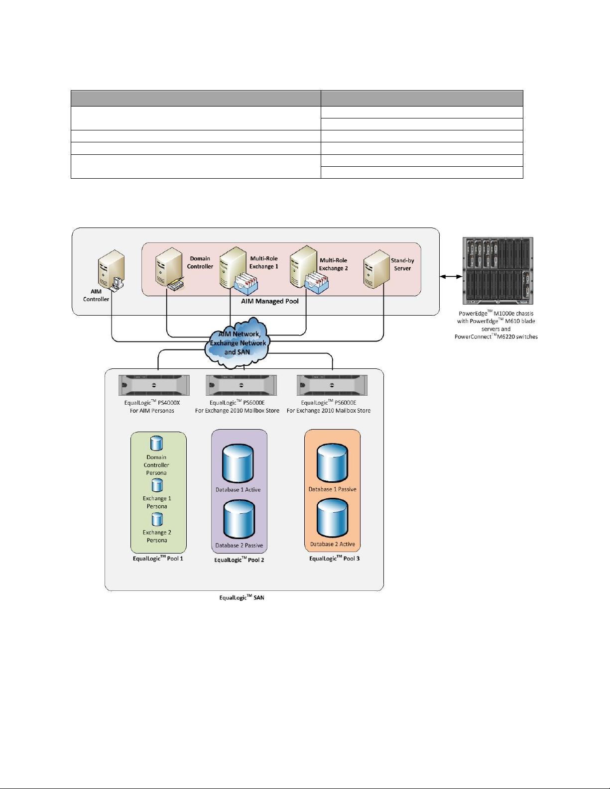
Figure 2. Exchange 2010 logical topology in AIM environment
Figure 2 shows the logical topology once the Exchange ecosystem is integrated with AIM. The AIM
managed pool now consists of four PowerEdge M610 blade servers, while the AIM controller runs on
another PowerEdge M610 blade. The persona images for the domain controller and multi-role Exchange
servers are stored on LUNs on EqualLogic PS4000X.
Page 10
Page 13

Migrating Exchange 2010 To Dell Advanced Infrastructure Manager Environment
Fabric A1
Public/MAPI Network
192.168.15.X / 24
VLAN 15
Fabric A2
Private/Replication Network
192.168.18.X / 24
VLAN 18
Fabric B1
Exchange iSCSI Database Network
192.168.16.X / 24
VLAN 16
Fabric B2
Exchange iSCSI Database Network
192.168.16.Y / 24
VLAN 16
Fabric C1
AIM SCN Network
192.168.14.X / 24
VLAN 14
Fabric C2
AIM SCN Network
192.168.14.Y / 24
VLAN 14
iDRAC
Management Network
192.168.17.X
VLAN 17
Deploying Exchange with AIM - A Brownfield scenario
This section describes setting up Exchange with AIM environment in a Brownfield scenario. A Brownfield
scenario assumes that an Exchange ecosystem already exists, and an AIM environment needs to be
integrated in a cooperative manner to the existing Exchange ecosystem. In this effort, we first plan and
set up an AIM environment suitable for the Exchange ecosystem, and then integrate it. We have an
existing topology to take in to consideration when deploying AIM and planning network architecture.
Also, the availability of Exchange services to Outlook clients is a major consideration. Taking advantage
of the application‘s native high availability (i.e. DAG), we migrate one server at a time into the AIM
environment, once setup is complete. The following subsections describe a step-by-step procedure to
deploy Exchange with AIM.
Preparation for an AIM Environment
This section describes the preparation of an AIM environment required to set up and/or integrate
Exchange 2010. Preparation was done with respect to AIM release 3.4.1 GA. Dell recommends that you
update the firmware on the modular switch fabrics PowerConnect M6220s, the Chassis Management
Controller (CMC), Integrated Dell Remote Access Controller (iDRAC), and the network interfaces as
mentioned in the AIM 3.4.1 GA interoperability matrix.
Network Planning for Exchange with AIM
AIM provides a ‗cable once and reconfigure repeatedly‘ kind of network environment. Dell recommends
planning for the design and deployment of the network scheme once, taking application and AIM
networking requirements into consideration. Exchange 2010 with SAN mounted databases has three
specific networks, a public (MAPI) network, private (replication) network, and iSCSI network for SAN
mounted databases. AIM requires its own network i.e. SCN.
Table 4. Networks for Exchange on AIM
The IP subnets mentioned in the above table are optional, and depict an example network scheme. In
order to mimic a typical Brownfield, Fabrics A1 and A2 are used for Exchange public and Exchange
private network respectively. Fabrics B1 and B2 are used for Exchange database iSCSI network enabled
for Multi Path I/O (MPIO). The C fabric is assumed to be unused, and NICs attached to these fabrics are
leveraged later for the AIM SCN once Exchange 2010 is incorporated into AIM environment.
Before proceeding further with your deployment please identify the NICs on the servers associated with
each fabric, and identify 2 channels available for the AIM SCN network. In order to support the above
network configuration, each PowerEdge M610 blade server used in the deployment requires two dual
port 1 Gb add-on mezzanine cards. The iDRAC management network is used by the AIM controller to
power-on and power-off servers using Intelligent Platform Management Interface (IPMI) commands. In
Page 11
Page 14

Migrating Exchange 2010 To Dell Advanced Infrastructure Manager Environment
an AIM environment, servers mapped to personas will be power-cycled typically during failover and
retarget scenarios.
Apart from the modular chassis switches, two top-of-the-rack PowerConnect 6248 switches are used in
the deployment configuration to perform routing between VLANs and are a redundant pair. The top-ofthe-rack switches are not managed by AIM. Figure 3 shows the physical cabling between the chassis,
EqualLogic arrays, and top-of-the-rack switches.
Figure 3. Physical cabling for Exchange on AIM: rack switches, blades and iSCSI storage
As can be seen from the above figure, there are two top-of-the-rack layer-3 switches that do all the
routing between the different VLANs. They are an active-active pair. The first 12 ports of each switch
are connected via a 2-port trunk to the M6220 modular switches are the back of the M1000e modular
enclosure. Ports 13-20 are used for iSCSI connections to the Exchange mailbox stores on two EqualLogic
PS 6000E enclosures. Port 21 is a direct connection to the CMC modules in the blade chassis. Ports 2324 are used for the iSCSI persona store on an EqualLogic PS 4000X. In the setup two 10Gbps uplink
modules were used to provide connectivity between the switches and Virtual Router Redundancy
Protocol (VRRP) was enabled. As an alternative to the 10Gbps links, the user may consider using
multiple trunked 1 Gbps links between the switches with the same configuration.
Page 12
Page 15

Migrating Exchange 2010 To Dell Advanced Infrastructure Manager Environment
The blade chassis has a total of six fabrics that can be used for 1 Gbps Ethernet networking and a
redundant pair of Chassis Management Controllers (CMC). The first fabric (A1) was used for the MAPI
network. The Domain Controller resides on this network. The second fabric (A2), is used for replication
of logs from active database copies to passive database copies. Fabrics B1 and B2 are used for iSCSI
connectivity to the Exchange mailbox store. The store consists of a total of 4 databases distributed
among two EqualLogic PS6000E storage enclosures. Each enclosure consists of one active and one
passive database copy. The AIM SCN network is used once Dell AIM has been introduced into the
environment. It resides on Fabric C.
The IP addresses are assigned dynamically in the AIM environment by a DHCP Server running on the
server running AIM controller. Two NIC‘s connected to Fabric C1 and C2 are bonded together to have a
network IP address of 192.168.14.5. As an alternative, the NIC attached to Fabric C1 can be assigned
this address and the NIC attached to fabric C2 can be left unconfigured. For deployment purposes, we
set up machines to run a Loadgen simulator and collect Performance data. These can be ignored for
production deployments.
In order to measure the performance of Exchange 2010 as accurately, Dell recommends that you design
and deploy separate storage groups for AIM operating system images (persona images) and Exchange
Databases/Information Store. Since the servers that are being managed by AIM receive IPs from the
DHCP server running on an AIM controller; the controller should have a range available to allocate the
IP addresses from. The AIM Web Console should be accessible using the management IP address from
other machines on the network.
Preparation for deploying AIM Software
This section explains how to prepare an environment to install AIM software. We planned to install AIM
controller on a Dell PowerEdge M610 blade server. The controller software runs on a Linux platform.
The Linux distribution recommended is Red Hat Enterprise Linux® version 5 update 5 (RHEL 5.5). The
following steps ensure creation of the correct environment for installing an AIM controller:
1. Install two PowerConnect M6220 switches into slots C1 and C2 with configurations per the
networking scheme.
2. Configure the ports on the Top of Rack 1 as per the networking scheme.
3. Configure the ports on the Top of Rack 2 as per the networking scheme.
4. Install RHEL 5.5 on the blade server designated as the AIM controller. The controller blade is
usually placed in slot 16 of the blade chassis.
5. During RHEL 5.5 installation:
o Use the default layout for partitions.
o For the Network Devices, remove the ‗Active on Boot‘ checkmark for eth0 and eth1 and
add the checkmark for eth4 and eth5. For simplicity, the AIM controller will use NICs
eth4 and eth5 on fabric C of the blade chassis. Fabric A and B are already used for
Exchange networking and iSCSI by other servers.
o The Software Development and Web Server packages do not need to be installed
o SELinux should be disabled.
6. On completion of RHEL 5.5, we are ready to configure the network interface setup.
o Dell recommends that you have bonded NICs for redundancy
o Optionally you can have a single network interface setup.
7. Configure your PowerEdge M1000e Modular enclosure Chassis Management Console.
8. Configure iDRAC users for all the servers that will be managed by AIM.
Page 13
Page 16

Migrating Exchange 2010 To Dell Advanced Infrastructure Manager Environment
Installing AIM Software
Gather the following information before beginning the installation of your controller software:
1. Controller IP address—this is the IP address that is used to access the Controller from the web
browser or CLI editor. It is not the IP address of the network interface.
2. System ID—More than one AIM environment can be installed in the same data center, or in data
centers that can communicate with each other. To ensure that the MAC addresses and other
configurations the controller creates are unique, a unique number from 0 to 31 must be
assigned to each AIM environment when installed.
3. Controller Services Virtual IP Address—This is the IP address configured to host the three
controller services: AIM console access (from GUI, CLI and SDK), communication with elements
in the AIM environment, and receive SNMP traps sent by network switches and other devices. In
a basic installation, a single IP address is configured to host all three services; this is a virtual
IP address and gets instantiated when the controller starts and typically binds to the same NIC
that the controller‘s real IP address is configured to use.
4. System Control Network (SCN) and AIM DHCP—This is a private network used by the controller
to communicate with the managed entities in the AIM environment. The AIM DHCP network is
used temporarily during the new server discovery process. The range of IPs for both networks
can be modified post installation; however, it is preferable to have this information entered in
during the installation process.
Install and configure the AIM controller software with the steps listed below:
1. Mount the AIM Linux media, and install the controller RPMs (packages) by executing the
installController.sh utility found in the root directory of the image. This utility will also
install any missing OS packages needed for AIM controller function. However, the utility needs
to refer to the Red Hat Enterprise Linux® installation media:
# ./installController.sh RedHatHost=<path to the Red Hat installation>.
E.g.:
# ./installController.sh RedHatHost=/dev/cdrom
The user may want to use an additional CD ROM or copy the AIM installation media locally in
order to refer to the Red Hat Installation later.
2. Configure the AIM controller by executing the /opt/dell/aim/bin/setupController.sh
utility. This utility will bring up a wizard that walks through the configuration process; the
questions are self-explanatory and customers should pick the ―Basic Installation‖. Once the
information detailed in the previous step is entered, the utility configures the installation.
3. Set the Controller IP address settings as shown in Figure 4. Note that this is the IP address that
Administrators will use to manage their AIM infrastructure through a HTTP session. Please
choose an IP address that will be convenient to recall at a later time.
Page 14
Page 17

Migrating Exchange 2010 To Dell Advanced Infrastructure Manager Environment
Figure 4. Controller Web Management IP Address Settings.
4. Set the parameters for the SCN Network – which should be on the same subnet as the
previously assigned IP address to the controller services. The DHCP and Discovery IP ranges
must not overlap and it is recommended that you have sufficiently large number of available IP
addresses available for your environment.
Figure 5. Parameters for the SCN Network and DHCP IP address range.
Page 15
Page 18

Migrating Exchange 2010 To Dell Advanced Infrastructure Manager Environment
5. In our scenario, the DHCP IP addresses would not be used since the Exchange Servers and
Active Directory have static IP addresses. This does not affect the ability to re-target a failed
persona on a stand-by server.
Installing the AIM License file and Final Steps
Once the installation is complete, the utility will prompt to copy the license.dat file provided when
the software was registered. This file needs to be copied to the /var/opt/dell/aim/license
directory on the controller. After the file is in place, run the command service aim start to start
the controller service. Open the web-browser to the controller services IP address, 192.168.14.10. Use
the following credentials: Username: admin, Password: admin. Verify that page similar to the following
opens up:
Figure 6. AIM Admin console screen
Page 16
Page 19

Migrating Exchange 2010 To Dell Advanced Infrastructure Manager Environment
AIM CLI Editor Setup and Use
AIM Editor Software provides a Command-line Interface (CLI) to configure, control and monitor the AIM
environment. It is distributed as part of Dell AIM Software Development Kit (SDK).
Starting CLI on Linux machine
The CLI can be accessed on a Linux machine with SDK installed. Typically the Linux machine running
the controller software has the SDK installed. In order to access the CLI:
Change to the directory where you installed the SDK (the default is /opt/dell/aim/bin):
# cd /opt/dell/aim/bin
# ./sdk shell=true
Starting CLI on Windows machine
A remote machine with a Windows server platform, capable of communicating with the AIM controller,
can also be used for hosting a remote AIM admin console and AIM Editor. The ‗setup_sdk‘ executable
available with the AIM software distribution should be used to set up the AIM Editor. AIM Simulator
software is also installed during this setup. On successful installation, open the Dell AIM Editor tool
present on the desktop.
Here are few commands to begin interacting with AIM environment:
- Login account=admin password=admin host=<controller IP address> protocol=http port=80
- Open: opens a fresh connection to the controller database.
- List <options>(switches / blades etc) : view the controller database contents
- Save <config/ all>: save the configuration changes made to the AIM environment
- Help: command that provides usage description of all other commands.
Note that you would want to change the controller IP address according to your configuration.
Figure 7. AIM CLI on Windows
Page 17
Page 20

Migrating Exchange 2010 To Dell Advanced Infrastructure Manager Environment
2
Migrating Exchange 2010 to AIM Environment
The Exchange 2010 solution considered in this paper consists of a two-copy DAG. We migrate one
Exchange 2010 multi-role servers one at a time in order to keep the databases available during the
migration process. Server Migration Utility (SMU) is used to copy the OS bits to the shared storage and
prepare them for net booting2.
Discovery of hardware components by AIM
AIM needs to identify the servers and switches in order to manage them. We discover and configure the
components in following order:
1. Discover PowerEdge M1000e modular enclosure (Needs CLI).
2. Discover chassis switches as well as top of rack (TOR) switches in read only mode.
3. Set the default channel ID for the switches (Needs CLI).
4. Configure the switchports on the chassis and TOR switches as host / unmanaged/ external /
interconnect from AIM console as needed (Needs CLI).
5. Update the switches to fully managed mode (Needs CLI).
6. Discover the Servers to be managed by AIM: This can be accomplished by simply restarting the
machine from the SMU. Ensure that a PXE boot is in progress. After a couple of minutes, the
server will shut down and the AIM console should show all the NIC‘s on the server with their
MAC addresses and channels. If all the NIC‘s have not been discovered, it may be necessary to
boot up the server in to the discovery image again.
Please refer to the CLI reference distributed with AIM documentation for detailed guide on using CLI
commands.
Migration using Server Migration Utility: Moving over to an image on SAN
The next step is to use the SMU and transition the Exchange servers, one at a time. In order to ensure
availability to end users, it is recommended that you migrate members of a DAG one at a time. For
example, in the test bed, all the copies of the database were mounted on Exchange-2 manually.
Exchange-1 was then rebooted into the SMU, moved over to the SAN on EqualLogic PS 4000X (Array 3)
first. Then the databases were mounted using the SAN image for Exchange-1. Migration of Exchange-2
was performed at this point and then the original High Availability (HA) pair configuration was
restored, with AIM managing the personas and networking. The single server migration process includes
copying the operating system image having Exchange 2010 multi-role server installed, from local disks
to SAN. Once copied, the newly copied image on the SAN needs to be prepared for network boot.
1. Boot into the SMU CD.
2. Copy the image from the local disk to the EqualLogic array
a. Advanced Operations > Mount a LUN via iSCSI connection
Enter your initiator (any string value) and target (192.168.14.50). Use the default port (3260)
3. Main Menu > Copy Windows Boot Image
a. Choose the local disk source (usually C)
b. Choose the iSCSI LUN previously created on the SAN array
Ensure that the iSCSI LUN is at least as large as the local disk‘s LUN before copying the image. Dell
recommends that you use 10k or 15k disks in your SAN for the OS images. The process to transfer the
image should take about five minutes. Reboot the machine once complete.
SMU version 3.4.3 or later should be used with AIM release 3.4.1 GA.
Page 18
Page 21

Migrating Exchange 2010 To Dell Advanced Infrastructure Manager Environment
4. Identify the Fabric C NIC‘s
Upon reboot, press <Ctrl+S> to enter the Network Configuration Menus. In the lab deployment, the
NIC‘s on Fabric C or PCI bus 05:00:00 and 5:00:01 were used for SCN networking. Note these two MAC
addresses. In the MBA Configuration menus for these two C channel NIC‘s choose the boot protocol as
PXE. All the other NIC‘s can be set to the default option (None). You would also need to enter the
System Setup menu (press <F2>) and update the boot priority so that the NICs are assigned higher
priority than the local disk.
5. Inject the drivers
Using the previously identified NICs, inject the drivers using the SMU to only these NICs. Identify them
using the MAC addresses just noted.
a. Mount the iSCSI LUN that contains the OS image just copied.
b. Advanced Operations > Prepare Image for iSCSI boot > Physical PXE > OS Volume on iSCSI
LUN
o Prepare the NIC attached to fabric C1
c. Repeat Step ‗b‘ for NIC attached to fabric C2.
Creation of Personas
Create Windows Server 2008 R2 personas for both Exchange servers considering following points:
- Either create persona in trunk or access mode depending on whether you desire to have
failover capabilities for the network interfaces on the SAN booted OS image
- Provide appropriate boot parameters
o Ensure boot method to be iSCSI boot
o Provide Storage details pertaining to EqualLogic group hosting OS images
- Specify Persona DNS, Gateways and routes pertaining to Networks per Exchange server
Creation of Server Pools
Server pools provide ability of server failovers. On detecting a server failure, the controller will
retarget the persona running on the failed server to a standby server within the pool, thereby resuming
the failed server OS, with some downtime for the application running on it. Create server pools
considering following points:
- Add the discovered servers (along with the stand-by server to the pool)
- Add the created personas to the pool
Creating and Configuring AIM Networks
This section has two parts; the first part describes how to configure AIM networks, while the second
section describes how to modify the Networks per persona (Exchange server) requirements.
Create AIM Networks
An Exchange ecosystem requires the configuration of three specific networks: public (MAPI) network,
private (Replication) network, and iSCSI database network. We created one AIM network per Exchange
network with corresponding configurations and taking into consideration following points:
- Specify the network IP address and the Netmask
- Specify primary and secondary channels and VLAN ID
- Assign Personas to the network
Page 19
Page 22

Migrating Exchange 2010 To Dell Advanced Infrastructure Manager Environment
Create three AIM networks corresponding to three Exchange networks.
Configure AIM Networks
While creating the networks, we added persona to them, which essentially establishes network
connections between the persona and the AIM networks. Once AIM networks are created, they should
be configured as per the persona requirements. Update an existing network connection of a persona:
- Set NetBIOS over TCP to ‗default‘
- Register with DNS to ‗default‘
- Set IP address type: ‗Manually set to fixed IP‘
- Manually add the IP addresses intended for the network interfaces on the OS; the Exchange
iSCSI network will have to IP addresses added manually for MPIO
Update all the three network connections for both personas.
Boot up Persona and Install Agent
Once the persona and its networking are configured, it is ready to be started. Before staring the
persona ensure server on which the persona will be started has the correct number of NICs for the
channels configured with the persona networks. Since the persona is part of server pool, you can
specify a server or let AIM select one for you. In the latter case, make sure all the servers in the pool
are discovered with an appropriate number of NICs mapped to corresponding persona network
channels.
When personas boot up, install the AIM agent software by running the ‗setup_persona‘ executable
provided with the AIM software for Windows platform. The AIM agent communicates with the controller
about the persona states, and also configures virtual networking on Windows. On completion of the
agent installation, the persona will reboot.
Bring up Exchange services and mount the DB Copies on AIM managed Exchange Server
Once the exch-1 persona booted with agent is installed, Exchange databases can be redistributed as
before. Exchange database 1 active copy can be mounted back on persona exch-1 and Exchange
database 2 passive copy can be resumed. At this time one of the Exchange servers is SAN booted and is
managed by AIM while other Exchange server (exch-2) is local booted and is AIM agnostic.
Completing the Migration by Migrating Second Exchange 2010 server
At this point in migration, both the databases can be mounted on persona exch-1. The unmanaged
server exch-2 can now be migrated to the AIM environment in the same way as migration of exch-1.
Once exch-2 is completely migrated to AIM, the databases can be redistributed so that the database 2
primary copy is mounted on persona exch-2. The exchange deployment is now fully migrated.
Page 20
Page 23

Migrating Exchange 2010 To Dell Advanced Infrastructure Manager Environment
Deploying Exchange with AIM - A Greenfield scenario
This section describes setting up an Exchange with AIM environment in a Greenfield scenario. A
Greenfield scenario assumes that both AIM and Exchange are yet to be deployed. We first set up the
AIM environment, and then deploy Exchange into the environment. The primary difference between a
Brownfield scenario and a Greenfield scenario is that there is no existing topology to take into
consideration when deploying AIM. Therefore the network planning is easier. Also, the availability of
Exchange services to Outlook clients is not a concern. The following subsections describe a step-by-step
deployment of Exchange with AIM.
Upgrading firmware
This is the first and most important step as it ensures efficiency in the AIM environment. The
preparation was done with respect to AIM release 3.4.1 GA. Dell recommends that you update the
firmware on the modular switch fabrics PowerConnect M6220s, the Chassis Management Console (CMC),
iDRAC and the network interfaces as mentioned in the AIM 3.4.1 GA interoperability matrix.
Plan and configure Networking
In a Greenfield scenario, the user has more flexibility in selecting fabrics for AIM SCN and Exchange
networking than that in a Brownfield scenario. Allocate chassis switch fabrics for:
- AIM SCN – boot NICs (E.g. Fabrics A1 and A2)
- Exchange public network (E.g. Fabric B1)
- Exchange private network (E.g. Fabric B2)
- Exchange iSCSI database network (E.g. Fabrics C1and C2)
Plan the VLANs for all the above networks and configure the chassis switches and top-of-the-rack
switches accordingly. Ensure that you configure Virtual Redundancy Routing Protocol (VRRP) on the
top-of-the-rack switches.
Install and setup AIM Controller software
Once the networking is configured, you can install the AIM controller software on a dedicated M610
blade server. Before you install the controller software, make sure you complete all the prerequisites:
follow prepare for AIM controller installation section described in the Brownfield scenario.
Discover the hardware resources to be managed by AIM
Refer to the Hardware discovery section of the Brownfield scenario.
Operating System Installation on local drives
Select a sample server with RAIDed local drives to install an operating system. Follow standard
installation of Windows 2008 R2 OS on the local drives in this case.
Prepare the image for net boot
Once the OS has been installed on the local drives, it can be migrated to SAN using SMU. Prepare the
boot NICs (Fabric A1 and A2) for iSCSI booting. Refer to the migration section in the Brownfield
environment. Make sure you refer to the fabrics selected for AIM in this scenario, e.g. A1 and A2.
Clone the Gold Copy
Preserve the OS image on the SAN prepared for iSCSI booting as a gold copy. Whenever needed, you
can clone this copy to save the OS installation time.
Page 21
Page 24

Migrating Exchange 2010 To Dell Advanced Infrastructure Manager Environment
Servers
2 x M610
Processor (per server)
2 x quad-core Intel X5550 @ 2.67GHz
Memory (per server)
48 GB
Operating System
Windows Server 2008 R2
Exchange Version
Exchange 2010 SP1
Storage
2 x Equallogic PS 6000E
Creation of Personas
Refer to the persona creation section.
Creation of Server Pools
Refer to the server pool creation section.
Creating and Configuring AIM Networks
Refer to the Creating and Configuring AIM Networks section.
Boot-up Persona and Install Agent
Refer to the Boot Persona and Install Agent Section
Install Exchange Server
Once the persona is up and ready with the agent, you can install Exchange 2010. This installation will
be carried out on the iSCSI LUN directly since the OS has iSCSI booted.
Create databases and users
On successful Exchange installation, you can create Exchange users as per the solution described in
Table 2
Advantages of AIM and Exchange 2010 DAG being used together
The Exchange 2010 Database Availability Group (DAG) provides application level High Availability (HA).
AIM provides HA at infrastructure level, and complements the native HA implemented through DAG in
Mailbox Server roles to provide greater fault tolerance to the Exchange ecosystem.
In case of server failure, AIM can compensate for the failed server by bringing up the persona on AIM
managed standby server. During failover, Exchange‘s native high availability would be in action first,
because the Active Manager would detect the failure at the application level, including the cluster
nodes. A standby server brought up by AIM would be ready for database redistribution.
For example, if the server running persona exch-1 fails, Exchange native HA would detect the failure
and activate the passive copies on the server running persona exch-2, thus providing continued
messaging service. AIM would also detect the failure of server running persona exch-1 and will retarget
the persona to the stand-by server in the pool. Once the persona exch-1 boots up on the standby
server, it is ready for hosting the database copies to mount on exch-1.
Performance Analysis of Exchange 2010
This section describes the lab results obtained by running Loadgen with AIM managed Exchange 2010
multi-role servers. Loadgen is simulator software from Microsoft used to evaluate the capabilities of
Exchange 2010 solutions. The lab setup consisted of two Exchange 2010 multi-role servers with the
following hardware configuration. The servers required at least 20 GB of memory. These servers were
part of two-copy DAG.
Table 5. Resource Configurations
Page 22
Page 25

Migrating Exchange 2010 To Dell Advanced Infrastructure Manager Environment
Disks (per storage unit)
16 x 500GB 7.2k SATA
RAID
2 x { RAID 10 of 14 disks + 2 hot spares }
LUN‘s (per storage unit)
2 (1 active / 1 passive)
Total Number of Active Databases
2
Total Number of Passive Databases
2
EqualLogic Controller Firmware
5.0.5
Number of pools
2 (1 member per pool)
Memory Requirement = 4 GB + 9MB per mailbox x 1800 users = at least 20GB.
Settings for Jumbo Maximum Transmission Unit (MTU) and flow-control were enabled on the switches
and server ports used for iSCSI communication. Each M610 had an active and a passive database copy
that were stored on a PS6000E array using 500GB SATA disks in RAID 10. The results collected are
summarized in the succeeding sections for Exchange 2010 stand-alone and Exchange 2010 with AIM.
The deployment with AIM consists of performance measurements for persona in access mode and trunk
mode scenarios. In all cases, the results are well within thresholds proposed by Microsoft. Three
scenarios were tested and validated. Loadgen tests were run for all three scenarios, and results are
expressed as the average of results from multiple tests.
Scenario 1: Standalone Exchange 2010 ecosystem, without AIM‘s management. Results pertaining to
this scenario are considered baseline results.
Scenario 2: Exchange 2010 integrated within AIM environment and Exchange servers are AIM-managed
with personas in access mode. Jumbo frames and Flow control were enabled during this scenario. This
configuration does allow Exchange to fail-over from one server to another within the AIM pool, but does
not offer NIC redundancy.
Scenario 3: Exchange 2010 integrated within AIM environment and Exchange server is AIM-managed
with personas in trunk mode. Personas in trunk mode allow not only failover within servers in a pool,
but also offer NIC failover within a server.
Database Latencies
The most important consideration in validating the Exchange deployment is whether or not active
database latencies are below their targets. Active database read and write latencies must be below 20
milliseconds (ms). Passive database read and write latencies can be much higher, and on average are
less than 200 ms. Latencies were measured using the MS Exchange Database counters. The read latency
is the time taken to read from a database file, and the write latency is the time taken to write to the
file. The results indicate no performance degradation from Scenario 1 to Scenario 2 or Scenario 3.
Figure 8 shows the active database latencies and Figure 9 shows passive database latencies for all the
three scenarios. The latencies associated with active database copies in non-AIM as well as AIM
environment are well within the threshold. With Exchange servers in AIM environment, there is
increase in latencies associated with passive database copies.
Page 23
Page 26

Migrating Exchange 2010 To Dell Advanced Infrastructure Manager Environment
Figure 8. Exchange 2010 active database latencies
Figure 9. Exchange 2010 passive database latencies
The average write latency for an active copy should be less than 20 ms, and indicates the time it takes
to write to a database file. Latencies on passive copies are typically higher since the IO size is larger.
Note that higher passive copy latencies will have no impact on end-user experience and functionality.
There is an increase in the passive database read latency when using personas in trunk mode but these
values were well within the 200 ms threshold provided by Microsoft. The database page fault stalls/sec
counter indicates the number of page faults that cannot be serviced because there are no pages
available in the database cache. This value is 0 as desired.
Page 24
Page 27

Migrating Exchange 2010 To Dell Advanced Infrastructure Manager Environment
Log Latencies
Log writes are indicators of the time taken to write log buffers to log files, and are indicators of active
copy performance. The log writes are sequential, and hence these transactions should be faster. The
threshold is 10 ms, and measured values are within the acceptable range. Log reads indicate the
typical time to read from a log file, and indicate log replay performance. These values are within the
desired range. The threshold is 200 ms. The Log Record Stalls indicate whether or not log records are
being written to log buffers. If this value exceeds the threshold of 10/sec, then the log buffers are full.
The values are within limits. Figure 10 shows the results for Exchange database Log read latencies and
Figure 11 shows the results for Exchange database Log write Latencies in case of all the three
scenarios.
Figure 10. Exchange 2010 database log latencies
Figure 11. Exchange 2010 database log latencies
From the above figures it can be seen that the read and write latencies have increased in scenario 3.
However, the latencies are well below their specified targets and should not impact Exchange
performance.
Page 25
Page 28
Migrating Exchange 2010 To Dell Advanced Infrastructure Manager Environment
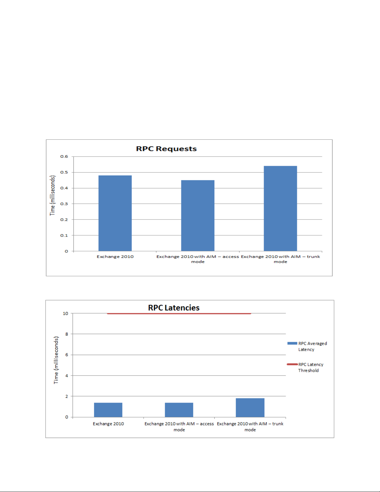
RPC Results
The ‗MSExchangeIS\RPC Requests‘ counter indicates the number of Remote Procedure Call (RPC)
requests that are being handled by the Information Store. The target limit specified for this counter is
70. The ‗RPC Averaged Latency‘ counter indicates the latency for all operations in the last 1024
packets and should be below 10 ms.
Figure 12 shows the results for RPC requests for all three scenarios. The counter shows increase in
value with scenario 3, but is within its target limits. Figure 13 shows the results for RPC latencies for
the three scenarios.
Figure 12. RPC requests
Figure 13. RPC latencies
Page 26
Page 29

Migrating Exchange 2010 To Dell Advanced Infrastructure Manager Environment
Exchange queue lengths
This section discusses the performance in terms of various queue lengths. The copy queue length
measures the number of logs that need to be copied from the active to the passive log folder, and
should be below. The replay queue length is the number of logs that are waiting to be replayed to the
passive copy, and the target value of this counter should be less than 5. Figure 14 shows the results for
these two counters. Both counters were observed within limits during the three test scenarios.
Figure 14. Queue length - mailbox
The number of submitted messages to the hub transport layer but not processed is indicated by the
‗Messages Queued for Submission‘ counter. This number is well within the threshold value. The total
messages queued for delivery in all queues is indicated by Aggregate Delivery Queue Length (All
Queues) and must be less than 3000. ‗Active Mailbox Delivery Queue Length‘ represents the number of
messages in active remote and mailbox delivery queues and this counter must be less than 250.
The submission queue should be less than 100 and it is represented by ‗Submission Queue Length‘
counter. The retry mailbox delivery queue consists of messages being attempted to be delivered to a
remote mailbox, indicated by ‗Retry Mailbox Delivery Queue Length‘; it should be less than 100. All the
queue lengths are optimal for all the three scenarios as shown Figure 15.
Page 27
Page 30

Migrating Exchange 2010 To Dell Advanced Infrastructure Manager Environment
Figure 15. Queue length – hub transport
Disk Latencies
This section describes the disk performance with Exchange installed and booted on local disks (Scenario
1) v/s Exchange booted from SAN (Scenario 2 and 3). The performance counters represent the latency
for Windows Server 2008 R2 with Exchange on local disk vs. Exchange on EqualLogic PS4000X single
array SAN as a RAID10 array. There seems to be a performance improvement in the disk latency when
moved in to the SAN. Figure 16 shows the values for corresponding counters. All these counters have
the limit of 20 ms.
Figure 16. Disk latencies
The counters above re-iterate the disk latencies that were observed for the database and log reads and
writes. They are within acceptable thresholds.
Page 28
Page 31

Migrating Exchange 2010 To Dell Advanced Infrastructure Manager Environment
Processor and Memory Utilization
This section discusses the processor and memory utilization in all the three scenarios. The processor
utilization was targeted at less than 75% at all times as a design validation requirement. This ensures
that all processes within the server are being executed in a timely fashion.
Memory plays an important role in your Exchange 2010 deployment as pages can be fetched faster
without having to go to disk. The total memory made available to each of the servers was 48 GB. Since
the memory manager in Exchange is designed to use as much physical memory as available, the Memory
Utilization is at approximately 36 GB, about 16 GB higher than the recommended 20 GB. Exchange 2010
collects pages to be written in memory and then performs fewer write operations to disk periodically,
thereby minimizing disk activity. For production deployments, the initial calculation of 20GB per server
should be sufficient. In our lab runs, 48 GB was available and was used. Figure 17 and Figure 18 show
the Processor and Memory utilization during the tests for all three scenarios.
Figure 17. Processor Utilization
Figure 18. Memory utilization
Page 29
Page 32

Migrating Exchange 2010 To Dell Advanced Infrastructure Manager Environment
Summary
The paper focuses on a method to migrate Exchange 2010 SP1 to an AIM managed environment – A
brownfield scenario. It also provides guidelines to freshly deploy Exchange 2010 in a newly configured
AIM environment. It is goes without saying that once migrated, Exchange 2010 in AIM environment
should be validated to see possible impact on its performance.
From the values discussed in the Performance Analysis section, it is clear that using Exchange 2010
with AIM does not affect the performance. The disk latencies are somewhat better with AIM. There is
an increase in the passive Database Write Latency with persona is configured in trunk mode, but these
values are well within thresholds. CPU and memory utilization is also comparable between AIM and
non-AIM environments.
Conclusion
In the case of Brownfield deployment, migration should be done one Exchange Server at a time to
ensure that there is no loss of service to end users. Greenfield deployments are simpler to implement
since the AIM controller networking can be setup as desired. The AIM management console, CLI with
auto-complete and SMU are the primary tools that work together to ease migration to an AIM
environment. Exchange on AIM presents an advantage to IT departments seeking to minimize
management overhead while not compromising on performance. The primary motivation for using AIM
is to separate your OS and application from local disks and make them available to a pool of servers. If
one server fails, the OS and application are brought up on another server in the same pool.
Page 30
Page 33

Migrating Exchange 2010 To Dell Advanced Infrastructure Manager Environment
References
Dell Advanced Infrastructure Manager
http://www.dell.com/aim
Dell Email Solutions
http://www.dell.com/exchange
Page 31
 Loading...