

Page 1

Dell Vostro 3471
Service Manual
Regulatory Model: D13S
Regulatory Type: D13S003
Page 2

Contents
1 Working on your computer............................................................................................................ 5
Safety instructions................................................................................................................................................................ 5
Turning off your computer — Windows 10....................................................................................................................... 5
Before working inside your computer................................................................................................................................. 6
After working inside your computer....................................................................................................................................6
2 Technology and components......................................................................................................... 7
USB features.......................................................................................................................................................................... 7
HDMI 1.4................................................................................................................................................................................. 9
3 Removing and installing components............................................................................................ 10
Recommended tools............................................................................................................................................................ 10
Screw size list.......................................................................................................................................................................10
System board layout.............................................................................................................................................................11
Cover..................................................................................................................................................................................... 12
Removing the cover.......................................................................................................................................................12
Installing the cover......................................................................................................................................................... 13
Front Bezel............................................................................................................................................................................14
Removing the front bezel..............................................................................................................................................14
Installing the front bezel................................................................................................................................................ 16
Cooling shroud......................................................................................................................................................................18
Removing the cooling shroud....................................................................................................................................... 18
Installing the cooling shroud..........................................................................................................................................19
Expansion card.....................................................................................................................................................................20
Removing the PCIe X1 expansion card-optional........................................................................................................20
Installing the PCIe X1 expansion card–optional......................................................................................................... 22
Removing the PCIe X16 expansion card–optional.....................................................................................................24
Installing the PCIe X16 expansion card–optional.......................................................................................................26
Installing PCIe expansion card in slot 1– optional...................................................................................................... 28
3.5-inch hard drive chassis................................................................................................................................................. 31
Removing the 3.5-inch hard drive chassis ................................................................................................................. 31
Installing the 3.5-inch hard drive chassis ...................................................................................................................33
3.5-inch hard drive........................................................................................................................................................ 35
Drive cage.............................................................................................................................................................................37
Removing the drive cage.............................................................................................................................................. 37
Installing the drive cage................................................................................................................................................ 38
Optical drive................................................................................................................................................................... 40
M.2 SATA SSD ....................................................................................................................................................................42
Removing M.2 SATA SSD ........................................................................................................................................... 42
Installing M.2 SATA SSD ..............................................................................................................................................43
WLAN card...........................................................................................................................................................................44
Removing the WLAN card............................................................................................................................................44
Installing the WLAN card.............................................................................................................................................. 45
Heat sink assembly..............................................................................................................................................................46
2 Contents
Page 3

Removing the heat sink assembly............................................................................................................................... 46
Installing the heat sink assembly..................................................................................................................................48
Memory modules.................................................................................................................................................................50
Removing the memory module....................................................................................................................................50
Installing the memory module....................................................................................................................................... 51
Power switch....................................................................................................................................................................... 52
Removing power switch............................................................................................................................................... 52
Installing the power switch...........................................................................................................................................54
Power supply unit................................................................................................................................................................56
Removing the power supply unit PSU........................................................................................................................ 56
Installing the power supply unit PSU.......................................................................................................................... 59
Coin-cell battery.................................................................................................................................................................. 62
Removing the coin cell battery.................................................................................................................................... 62
Installing the coin cell battery.......................................................................................................................................63
Processor..............................................................................................................................................................................64
Removing the processor...............................................................................................................................................64
Installing the processor.................................................................................................................................................65
System board.......................................................................................................................................................................66
Removing the system board........................................................................................................................................ 66
Installing the system board............................................................................................................................................71
TPM 2.0 installation.......................................................................................................................................................76
4 Troubleshooting......................................................................................................................... 79
Enhanced Pre-Boot System Assessment — ePSA diagnostics................................................................................... 79
Running the ePSA Diagnostics.....................................................................................................................................79
Diagnostics........................................................................................................................................................................... 80
Diagnostic error messages................................................................................................................................................. 80
System error messages...................................................................................................................................................... 83
5 Getting help...............................................................................................................................84
Contacting Dell.................................................................................................................................................................... 84
Contents
3
Page 4

Identifier GUID-5B8DE7B7-879F-45A4-88E0-732155904029
Status Released
Notes, cautions, and warnings
NOTE: A NOTE indicates important information that helps you make better use of your product.
CAUTION: A CAUTION indicates either potential damage to hardware or loss of data and tells you how to avoid the
problem.
WARNING: A WARNING indicates a potential for property damage, personal injury, or death.
© 2019 -2020 Dell Inc. or its subsidiaries. All rights reserved. Dell, EMC, and other trademarks are trademarks of Dell Inc. or its
subsidiaries. Other trademarks may be trademarks of their respective owners.
2019 - 08
Rev. A00
Page 5

1
Identifier GUID-9CCD6D90-C1D1-427F-9E77-D4F83F3AD2B6
Status Released
Working on your computer
Identifier GUID-9821EDD0-9810-4752-8B3C-AF89B67C2DB0
Status Released
Safety instructions
GUID-9821EDD0-9810-4752-8B3C-AF89B67C2DB0
Use the following safety guidelines to protect your computer from potential damage and to ensure your personal safety. Unless otherwise
noted, each procedure included in this document assumes that the following conditions exist:
• You have read the safety information that shipped with your computer.
• A component can be replaced or, if purchased separately, installed by performing the removal procedure in reverse order.
NOTE: Disconnect all power sources before opening the computer cover or panels. After you finish working inside the
computer, replace all covers, panels, and screws before connecting to the power source.
WARNING: Before working inside your computer, read the safety information that shipped with your computer. For
additional safety best practices information, see the Regulatory Compliance Homepage
CAUTION: Many repairs may only be done by a certified service technician. You should only perform troubleshooting and
simple repairs as authorized in your product documentation, or as directed by the online or telephone service and
support team. Damage due to servicing that is not authorized by Dell is not covered by your warranty. Read and follow
the safety instructions that came with the product.
CAUTION: To avoid electrostatic discharge, ground yourself by using a wrist grounding strap or by periodically touching
an unpainted metal surface at the same time as touching a connector on the back of the computer.
CAUTION: Handle components and cards with care. Do not touch the components or contacts on a card. Hold a card by
its edges or by its metal mounting bracket. Hold a component such as a processor by its edges, not by its pins.
CAUTION: When you disconnect a cable, pull on its connector or on its pull-tab, not on the cable itself. Some cables
have connectors with locking tabs; if you are disconnecting this type of cable, press in on the locking tabs before you
disconnect the cable. As you pull connectors apart, keep them evenly aligned to avoid bending any connector pins. Also,
before you connect a cable, ensure that both connectors are correctly oriented and aligned.
NOTE: The color of your computer and certain components may appear differently than shown in this document.
Identifier GUID-7AC629FC-CB78-43E9-83EF-6B8836FDDAD4
Status Released
Turning off your computer — Windows 10
GUID-7AC629FC-CB78-43E9-83EF-6B8836FDDAD4
CAUTION:
computer or remove the side cover.
To avoid losing data, save and close all open files and exit all open programs before you turn off your
1. Click or tap .
2. Click or tap and then click or tap Shut down.
Working on your computer 5
Page 6

NOTE: Ensure that the computer and all attached devices are turned off. If your computer and attached devices did
not automatically turn off when you shut down your operating system, press and hold the power button for about 6
seconds to turn them off.
Identifier GUID-CEF5001C-74CA-41CA-8C75-25E2A80E8909
Status Released
Before working inside your computer
GUID-CEF5001C-74CA-41CA-8C75-25E2A80E8909
To avoid damaging your computer, perform the following steps before you begin working inside the computer.
1. Ensure that you follow the Safety Instruction.
2. Ensure that your work surface is flat and clean to prevent the computer cover from being scratched.
3. Turn off your computer.
4. Disconnect all network cables from the computer.
CAUTION: To disconnect a network cable, first unplug the cable from your computer and then unplug the cable from
the network device.
5. Disconnect your computer and all attached devices from their electrical outlets.
6. Press and hold the power button while the computer is unplugged to ground the system board.
NOTE: To avoid electrostatic discharge, ground yourself by using a wrist grounding strap or by periodically touching
an unpainted metal surface at the same time as touching a connector on the back of the computer.
Identifier GUID-F99E5E0D-8C96-4B55-A6C9-5722A035E20C
Status Released
After working inside your computer
GUID-F99E5E0D-8C96-4B55-A6C9-5722A035E20C
After you complete any replacement procedure, ensure that you connect any external devices, cards, and cables before turning on your
computer.
1. Connect any telephone or network cables to your computer.
CAUTION:
computer.
2. Connect your computer and all attached devices to their electrical outlets.
3. Turn on your computer.
4. If required, verify that the computer works correctly by running ePSA diagnostics.
To connect a network cable, first plug the cable into the network device and then plug it into the
6
Working on your computer
Page 7

Identifier GUID-185D6308-9C53-4477-B3DB-8203E60E623A
Status Released
Technology and components
Identifier GUID-2FE1F42C-4FCF-4580-9C68-D258E212454D
Status Released
USB features
GUID-2FE1F42C-4FCF-4580-9C68-D258E212454D
Universal Serial Bus, or USB, was introduced in 1996. It dramatically simplified the connection between host computers and peripheral
devices like mice, keyboards, external drivers, and printers.
Let's take a quick look on the USB evolution referencing to the table below.
Table 1. USB evolution
Type Data Transfer Rate Category Introduction Year
USB 2.0 480 Mbps High Speed 2000
USB 3.0/USB 3.1 Gen 1 5 Gbps Super Speed 2010
USB 3.1 Gen 2 10 Gbps Super Speed 2013
2
USB 3.0/USB 3.1 Gen 1 (SuperSpeed USB)
For years, the USB 2.0 has been firmly entrenched as the de facto interface standard in the PC world with about 6 billion devices sold, and
yet the need for more speed grows by ever faster computing hardware and ever greater bandwidth demands. The USB 3.0/USB 3.1 Gen 1
finally has the answer to the consumers' demands with a theoretically 10 times faster than its predecessor. In a nutshell, USB 3.1 Gen 1
features are as follows:
• Higher transfer rates (up to 5 Gbps)
• Increased maximum bus power and increased device current draw to better accommodate power-hungry devices
• New power management features
• Full-duplex data transfers and support for new transfer types
• Backward USB 2.0 compatibility
• New connectors and cable
The topics below cover some of the most commonly asked questions regarding USB 3.0/USB 3.1 Gen 1.
Speed
Currently, there are 3 speed modes defined by the latest USB 3.0/USB 3.1 Gen 1 specification. They are Super-Speed, Hi-Speed and FullSpeed. The new SuperSpeed mode has a transfer rate of 4.8Gbps. While the specification retains Hi-Speed, and Full-Speed USB mode,
commonly known as USB 2.0 and 1.1 respectively, the slower modes still operate at 480Mbps and 12Mbps respectively and are kept to
maintain backward compatibility.
USB 3.0/USB 3.1 Gen 1 achieves the much higher performance by the technical changes below:
• An additional physical bus that is added in parallel with the existing USB 2.0 bus (refer to the picture below).
Technology and components 7
Page 8
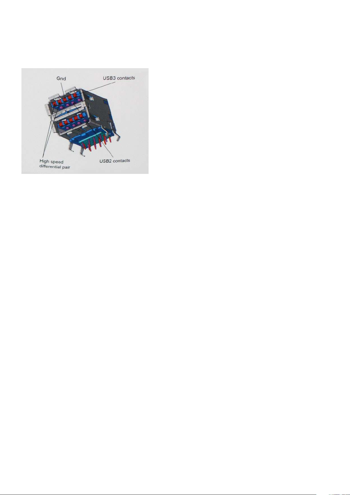
• USB 2.0 previously had four wires (power, ground, and a pair for differential data); USB 3.0/USB 3.1 Gen 1 adds four more for two
pairs of differential signals (receive and transmit) for a combined total of eight connections in the connectors and cabling.
• USB 3.0/USB 3.1 Gen 1 utilizes the bidirectional data interface, rather than USB 2.0's half-duplex arrangement. This gives a 10-fold
increase in theoretical bandwidth.
With today's ever increasing demands placed on data transfers with high-definition video content, terabyte storage devices, high
megapixel count digital cameras etc., USB 2.0 may not be fast enough. Furthermore, no USB 2.0 connection could ever come close to the
480Mbps theoretical maximum throughput, making data transfer at around 320Mbps (40MB/s) — the actual real-world maximum.
Similarly, USB 3.0/USB 3.1 Gen 1 connections will never achieve 4.8Gbps. We will likely see a real-world maximum rate of 400MB/s with
overheads. At this speed, USB 3.0/USB 3.1 Gen 1 is a 10x improvement over USB 2.0.
Applications
USB 3.0/USB 3.1 Gen 1 opens up the laneways and provides more headroom for devices to deliver a better overall experience. Where USB
video was barely tolerable previously (both from a maximum resolution, latency, and video compression perspective), it's easy to imagine
that with 5-10 times the bandwidth available, USB video solutions should work that much better. Single-link DVI requires almost 2Gbps
throughput. Where 480Mbps was limiting, 5Gbps is more than promising. With its promised 4.8Gbps speed, the standard will find its way
into some products that previously weren't USB territory, like external RAID storage systems.
Listed below are some of the available SuperSpeed USB 3.0/USB 3.1 Gen 1 products:
• External Desktop USB 3.0/USB 3.1 Gen 1 Hard Drives
• Portable USB 3.0/USB 3.1 Gen 1 Hard Drives
• USB 3.0/USB 3.1 Gen 1 Drive Docks & Adapters
• USB 3.0/USB 3.1 Gen 1 Flash Drives & Readers
• USB 3.0/USB 3.1 Gen 1 Solid-state Drives
• USB 3.0/USB 3.1 Gen 1 RAIDs
• Optical Media Drives
• Multimedia Devices
• Networking
• USB 3.0/USB 3.1 Gen 1 Adapter Cards & Hubs
Compatibility
The good news is that USB 3.0/USB 3.1 Gen 1 has been carefully planned from the start to peacefully co-exist with USB 2.0. First of all,
while USB 3.0/USB 3.1 Gen 1 specifies new physical connections and thus new cables to take advantage of the higher speed capability of
the new protocol, the connector itself remains the same rectangular shape with the four USB 2.0 contacts in the exact same location as
before. Five new connections to carry receive and transmitted data independently are present on USB 3.0/USB 3.1 Gen 1 cables and only
come into contact when connected to a proper SuperSpeed USB connection.
8
Technology and components
Page 9

Identifier GUID-F015869F-9930-4CD6-A002-678BC87259A3
Status Released
HDMI 1.4
GUID-F015869F-9930-4CD6-A002-678BC87259A3
This topic explains the HDMI 1.4 and its features along with the advantages.
HDMI (High-Definition Multimedia Interface) is an industry-supported, uncompressed, all-digital audio/video interface. HDMI provides an
interface between any compatible digital audio/video source, such as a DVD player, or A/V receiver and a compatible digital audio and/or
video monitor, such as a digital TV (DTV). The intended applications for HDMI TVs, and DVD players. The primary advantage is cable
reduction and content protection provisions. HDMI supports standard, enhanced, or high-definition video, plus multichannel digital audio
on a single cable.
NOTE: The HDMI 1.4 will provide 5.1 channel audio support.
HDMI 1.4 Features
• HDMI Ethernet Channel - Adds high-speed networking to an HDMI link, allowing users to take full advantage of their IP-enabled
devices without a separate Ethernet cable
• Audio Return Channel - Allows an HDMI-connected TV with a built-in tuner to send audio data "upstream" to a surround audio
system, eliminating the need for a separate audio cable
• 3D - Defines input/output protocols for major 3D video formats, paving the way for true 3D gaming and 3D home theater applications
• Content Type - Real-time signaling of content types between display and source devices, enabling a TV to optimize picture settings
based on content type
• Additional Color Spaces - Adds support for additional color models used in digital photography and computer graphics
• 4K Support - Enables video resolutions far beyond 1080p, supporting next-generation displays that will rival the Digital Cinema
systems used in many commercial movie theaters
• HDMI Micro Connector - A new, smaller connector for phones and other portable devices, supporting video resolutions up to 1080p
• Automotive Connection System - New cables and connectors for automotive video systems, designed to meet the unique
demands of the motoring environment while delivering true HD quality
Advantages of HDMI
• Quality HDMI transfers uncompressed digital audio and video for the highest, crispest image quality.
• Low -cost HDMI provides the quality and functionality of a digital interface while also supporting uncompressed video formats in a
simple, cost-effective manner
• Audio HDMI supports multiple audio formats from standard stereo to multichannel surround sound
• HDMI combines video and multichannel audio into a single cable, eliminating the cost, complexity, and confusion of multiple cables
currently used in A/V systems
• HDMI supports communication between the video source (such as a DVD player) and the DTV, enabling new functionality
Technology and components
9
Page 10
Identifier GUID-7FBB11D7-9820-47BB-AFAA-48FA912314D9
Status Released
Removing and installing components
Identifier GUID-6B3E81F5-5AC2-45BF-B1DD-36F28AC108A5
Status Released
Recommended tools
GUID-6B3E81F5-5AC2-45BF-B1DD-36F28AC108A5
The procedures in this document require the following tools:
• Phillips # 1 screwdriver
• Phillips # 2 screwdriver
• Small plastic scribe
3
Identifier
Status Released
GUID-9DC45B3A-E001-444B-B431-BDFD458CA89B
Screw size list
GUID-9DC45B3A-E001-444B-B431-BDFD458CA89B
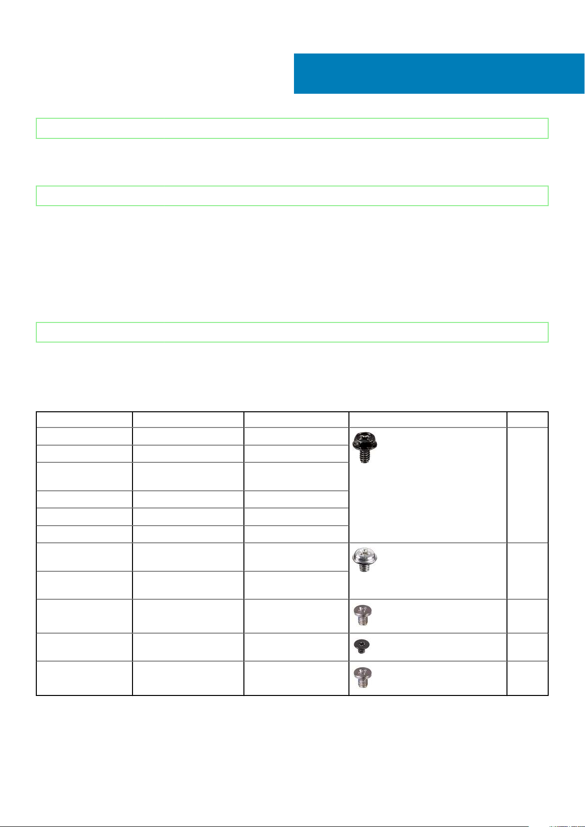
Table 2. Vostro 3471
Component Screw type Quantity Image Color
System board 6-32xL6.35 6 Black
Power Supply Unit 6-32xL6.35 3
3.5-inch hard drive
chassis
Drive cage 6-32xL6.35 1
Cover 6-32xL6.35 2
IO bracket 6-32xL6.35 1
3.5-inch hard drive to
3.5- hard drive bracket
2.5-inch hard drive
chassis
2.5–inch hard drive to
drive bracket
6-32xL6.35 2
6-32xL3.6 2 Silver
6-32xL3.6 1
M3x3.5 4 Silver
Optical drive to optical
drive bracket
WLAN card M2x3.5 1 Silver
10 Removing and installing components
M2x2 3 Black
Page 11

Identifier GUID-0B939728-5042-4649-AE68-D97898E910B7
Status Released
System board layout
GUID-0B939728-5042-4649-AE68-D97898E910B7
1. Power switch connector
2. M.2 connector for WIFI card
3. Coin cell battery connector
4. SATA power connector (Black)
5. SATA0 connector (Blue)
6. SATA3 connector (Black)
7. ATX Power Connector(ATX_SYS)
8. SATA2 connector (White)
9. Service mode / password clear/CMOS clear jumpers
10. PCI-e X16 Connector(SLOT2)
11. PCI-e X1 Connector(SLOT1)
12. M.2 SATA Connector for SSD
13. Processor socket
14. CPU Power Connector(ATX_CPU)
15. CPU Fan Connector(FAN_CPU)
16. Memory-module slots (DIMM1, DIMM2)
Removing and installing components
11
Page 12
Identifier GUID-E4057972-BBB3-4E21-904F-8F96933795B9
Status Released
Cover
GUID-E4057972-BBB3-4E21-904F-8F96933795B9
Identifier GUID-040FD613-8469-40DD-B4FA-D8BDF1FB6559
Status Released
Removing the cover
GUID-040FD613-8469-40DD-B4FA-D8BDF1FB6559
1. Follow the procedure in Before working inside your computer.
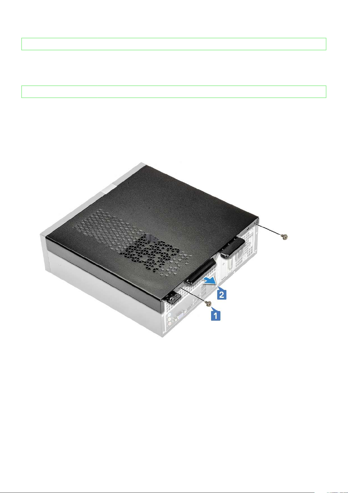
2. Follow the steps to remove the cover:
a) Remove the two 6-32xL6.35 screws that secure the cover to the computer [1].
b) Slide the computer cover towards the back of the computer [2].
c) Lift and remove the cover from the computer .
12
Removing and installing components
Page 13

Identifier GUID-CDC47A10-166B-4047-8DB6-F73859DC4177
Status Released
Installing the cover
GUID-CDC47A10-166B-4047-8DB6-F73859DC4177
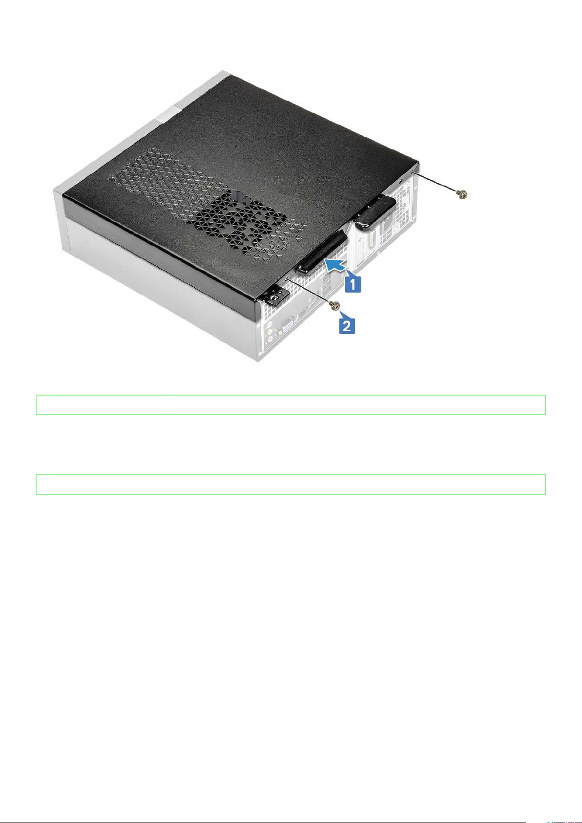
1. Slide the cover from the back of the computer, until the latches snap-in [1].
2. Replace the two 6-32xL6.35 screws to secure the cover [2].
Removing and installing components
13
Page 14
3. Follow the procedures in After Working Inside Your Computer
Identifier
Status Released
GUID-A73EBADB-AAC5-4773-9725-D58B244270EA
Front Bezel
GUID-A73EBADB-AAC5-4773-9725-D58B244270EA
Identifier
Status Released
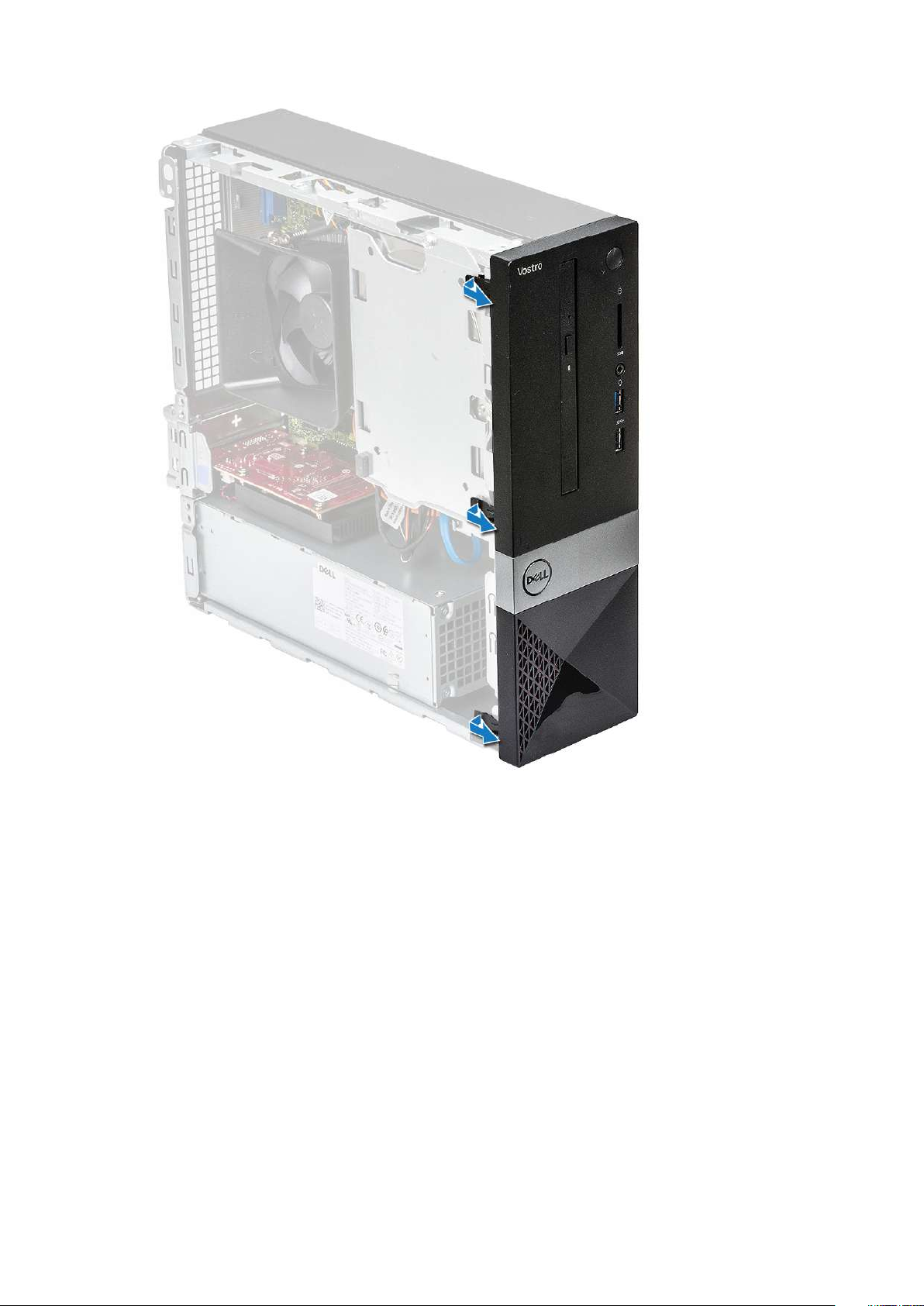
Removing the front bezel
GUID-568701C6-B538-4379-B228-0F8EFECDDBF9
1. Follow the procedure in Before working inside your computer.
2. Remove cover.
3. Follow the steps to remove the front bezel:
a) Pull the tabs to remove the front bezel.
GUID-568701C6-B538-4379-B228-0F8EFECDDBF9
14
Removing and installing components
Page 15
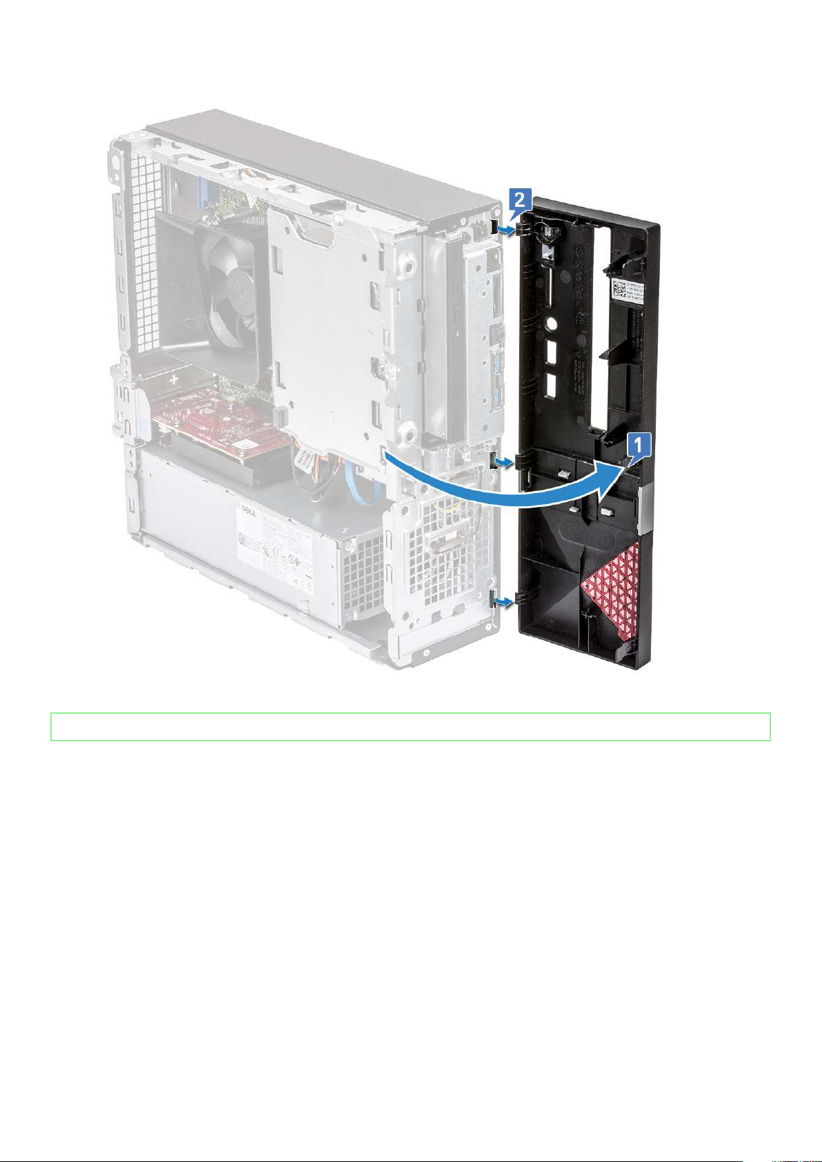
b) Rotate the front bezel away from the computer [1] and pull to release the tabs on the front bezel from the front-panel slots [2].
Removing and installing components
15
Page 16
Identifier GUID-15B3D0BB-388E-40BA-88D8-3E5AEDB338A4
Status Released
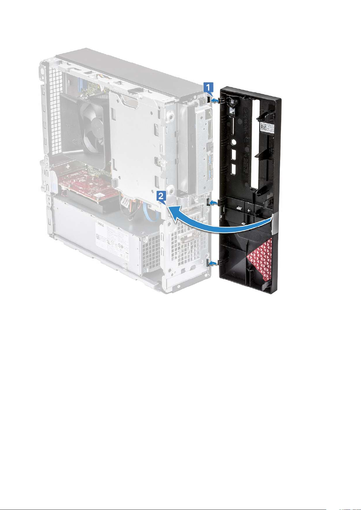
Installing the front bezel
GUID-15B3D0BB-388E-40BA-88D8-3E5AEDB338A4
1. Hold the bezel and ensure that the hooks on the tabs snap into the notches on the computer [1].
2. Rotate the front bezel toward the front of the computer [2].
16
Removing and installing components
Page 17
3. Press the front bezel until the tabs snap in.
Removing and installing components
17
Page 18
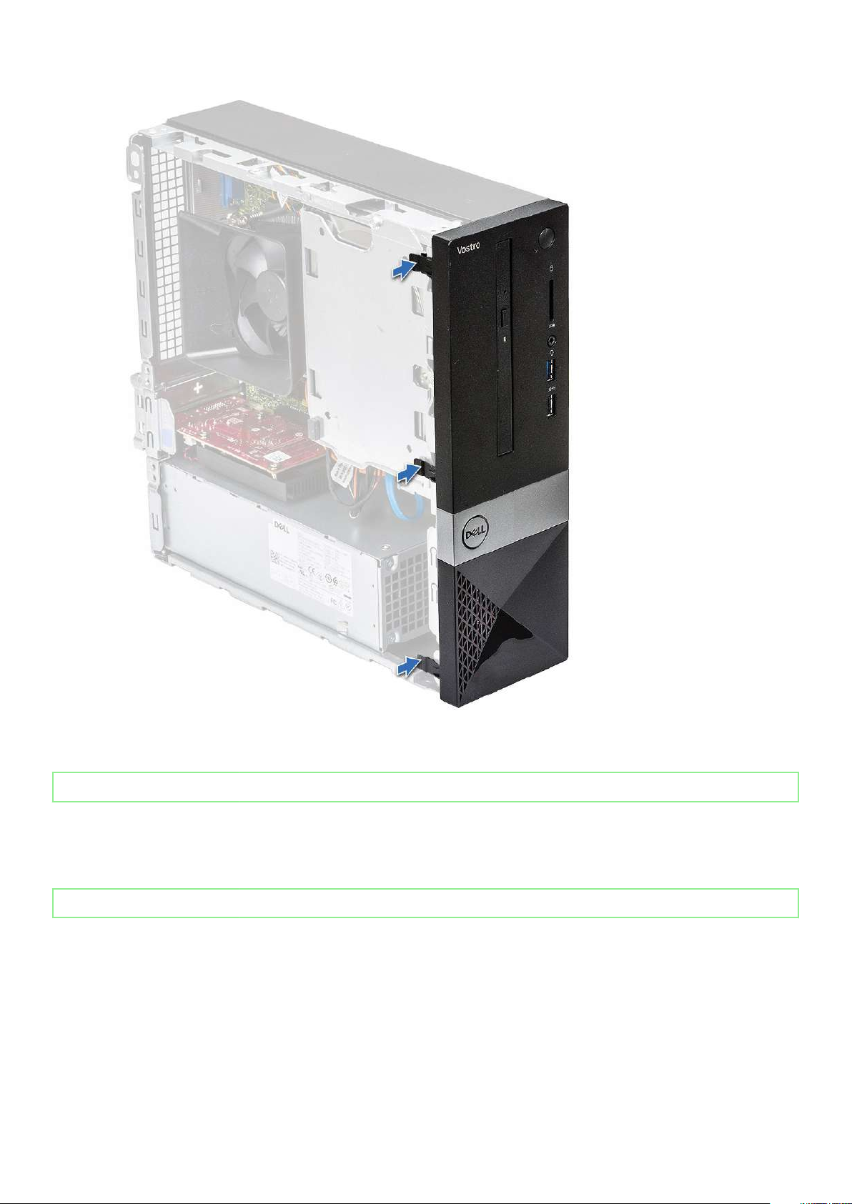
4. Install the cover.
5. Follow the procedure in After Working Inside Your Computer.
Identifier
Status Released
GUID-60A52EA6-2990-49F4-9800-B9A7C0A5D6BC
Cooling shroud
GUID-60A52EA6-2990-49F4-9800-B9A7C0A5D6BC
Identifier
Status Released
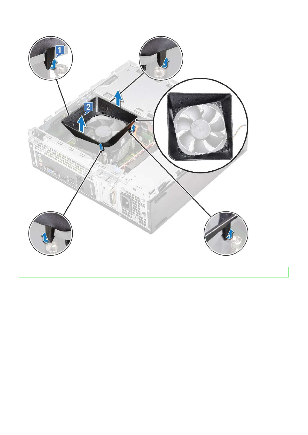
Removing the cooling shroud
GUID-6B576122-84FB-401B-8D7A-C21EA01FA0F6
1. Follow the procedure in Before working inside your computer.
2. Remove the cover
3. Follow the steps to remove the heat sink fan cover:
a) Pry the plastic notches that secure the fan cover in an outward direction [1].
b) Remove the fan cover from the heat sink assembly [2].
18
Removing and installing components
GUID-6B576122-84FB-401B-8D7A-C21EA01FA0F6
Page 19
Identifier GUID-28CDA800-289E-4E4C-9FCA-EE0C9C52D5C1
Status Released
Installing the cooling shroud
GUID-28CDA800-289E-4E4C-9FCA-EE0C9C52D5C1
1. Align the tabs on the cooling shroud with the securing slots on the computer.
2. Lower the cooling shroud into the chassis until the notches secure with a click sound and the cooling shroud is firmly seated.
Removing and installing components
19
Page 20
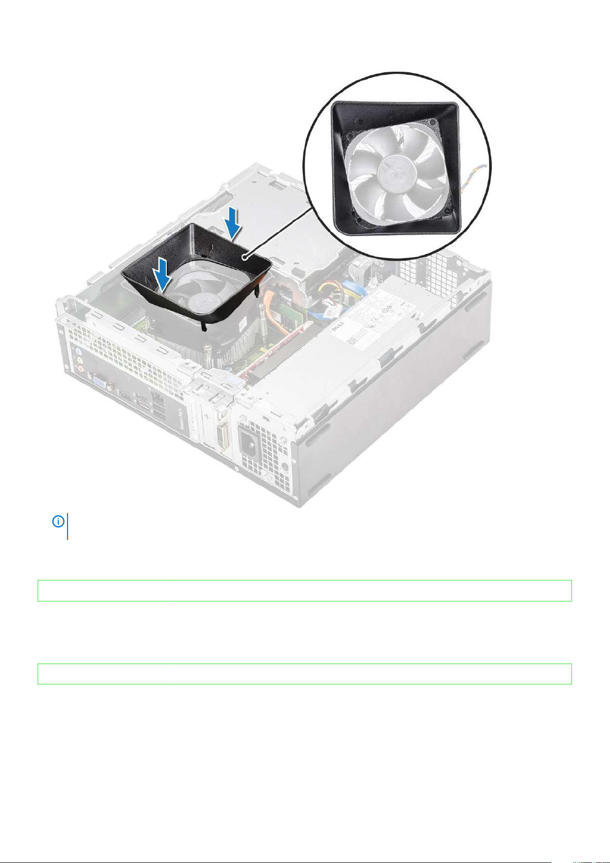
NOTE: Make sure the cooling shroud is placed such that the 'REAR' mark on the cooling shroud is towards the rear
side of the system.
3. Install the cover.
4. Follow the procedure in After Working Inside Your Computer.
Identifier
Status Released
GUID-14C0D031-FA0A-4269-B841-B2EBD0633192
Expansion card
GUID-14C0D031-FA0A-4269-B841-B2EBD0633192
Identifier
Status Released
Removing the PCIe X1 expansion card-optional
GUID-4F12F1C3-22A1-4861-AEBA-F624D63B8F75
1. Follow the procedure in Before working inside your computer.
2. Remove the cover.
3. Perform the following steps to remove the expansion card:
20
Removing and installing components
GUID-4F12F1C3-22A1-4861-AEBA-F624D63B8F75
Page 21
a) Pull the metal tab to release the expansion card.
b) Remove the expansion card from the slot on the computer
Removing and installing components
21
Page 22
Identifier GUID-2B8B9C30-2700-427F-9D78-840417C7153D
Status Released
Installing the PCIe X1 expansion card–optional
GUID-2B8B9C30-2700-427F-9D78-840417C7153D
1. Insert the expansion card on the slot.
22
Removing and installing components
Page 23
2. Push the metal tab until it snaps in place.
Removing and installing components
23
Page 24
3. Install the cover
4. Follow the procedure in After Working Inside Your Computer.
Identifier
Status Released
GUID-9CB95972-CD04-4F3C-8910-BC99DF8E6C6A
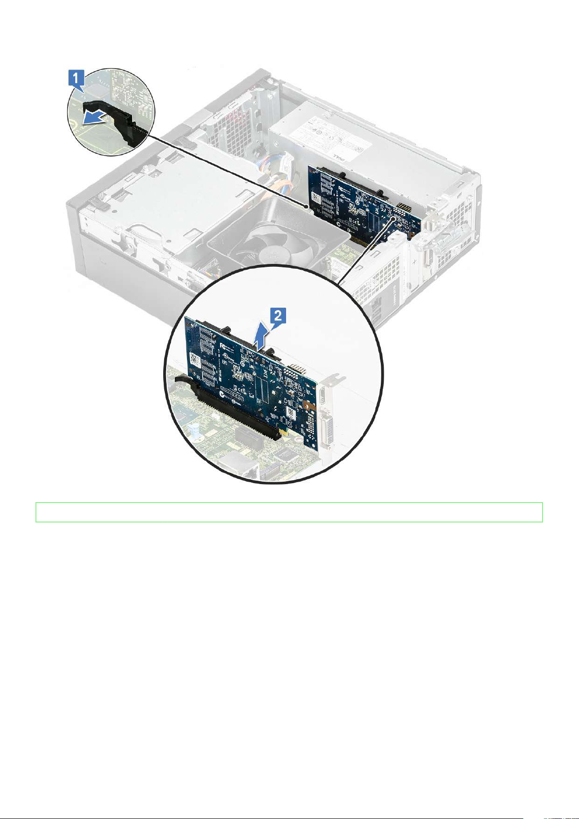
Removing the PCIe X16 expansion card–optional
GUID-9CB95972-CD04-4F3C-8910-BC99DF8E6C6A
1. Follow the procedure in Before working inside your computer.
2. Remove the cover.
3. Perform the following steps to remove the expansion card:
a) Pull the metal tab to release the expansion card.
24
Removing and installing components
Page 25
b) Pull the card-retention tab [1], and remove the expansion card from the slot on the computer [2].
Removing and installing components
25
Page 26
Identifier GUID-E3A861CA-4F34-46F4-977A-0245E619E662
Status Released
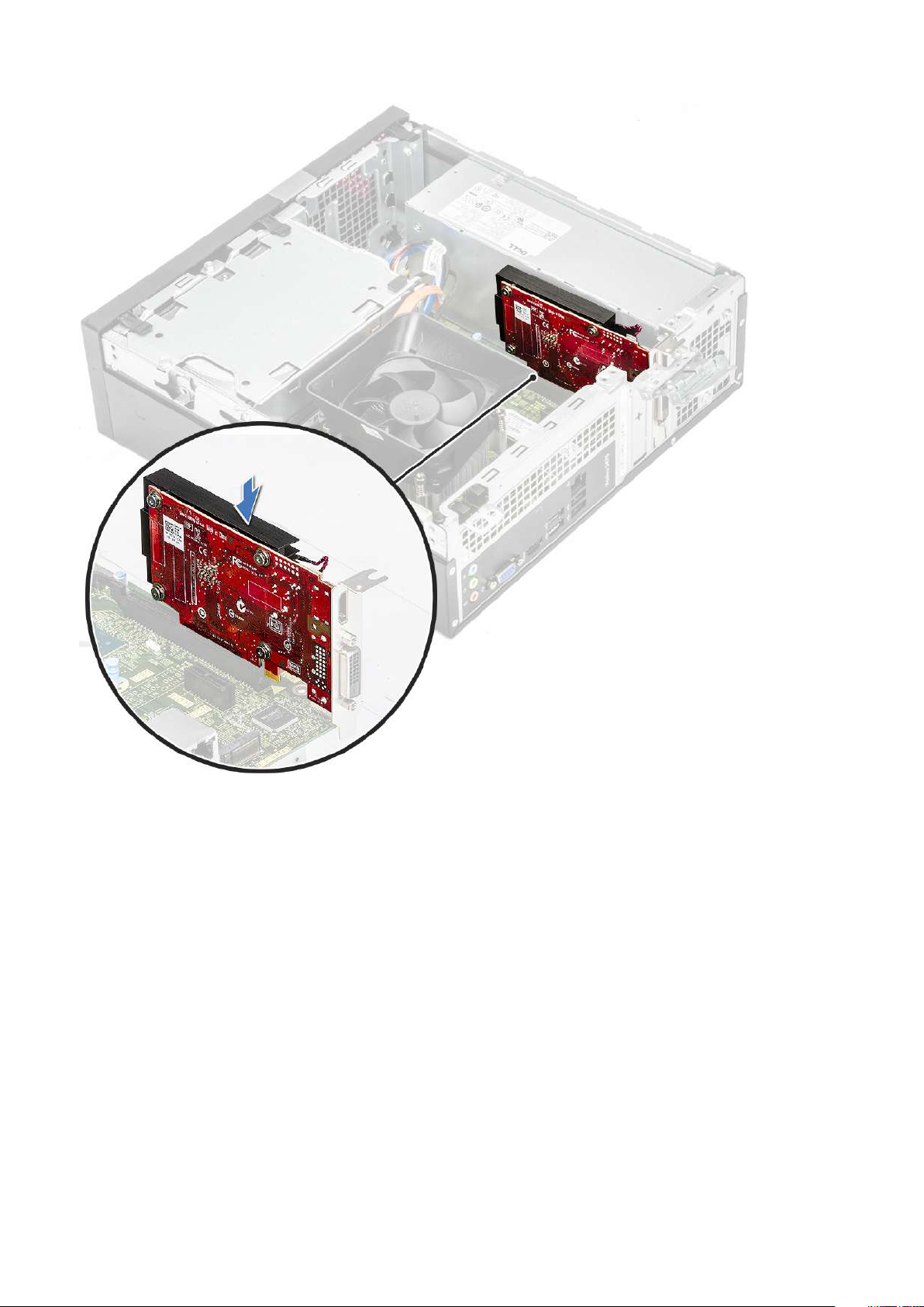
Installing the PCIe X16 expansion card–optional
GUID-E3A861CA-4F34-46F4-977A-0245E619E662
1. Insert the expansion card on the slot [1].
2. Push the card-retention latch to secure the expansion card [2].
26
Removing and installing components
Page 27

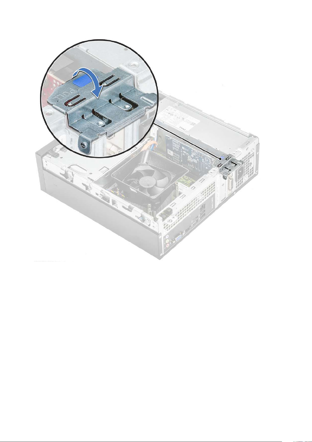
3. Push the metal tab until it snaps in place.
Removing and installing components
27
Page 28

4. Install the cover
5. Follow the procedure in After Working Inside Your Computer.
Identifier
Status Released
GUID-1FD8C8BB-5E57-4632-B82F-6BD5C3ED76B8
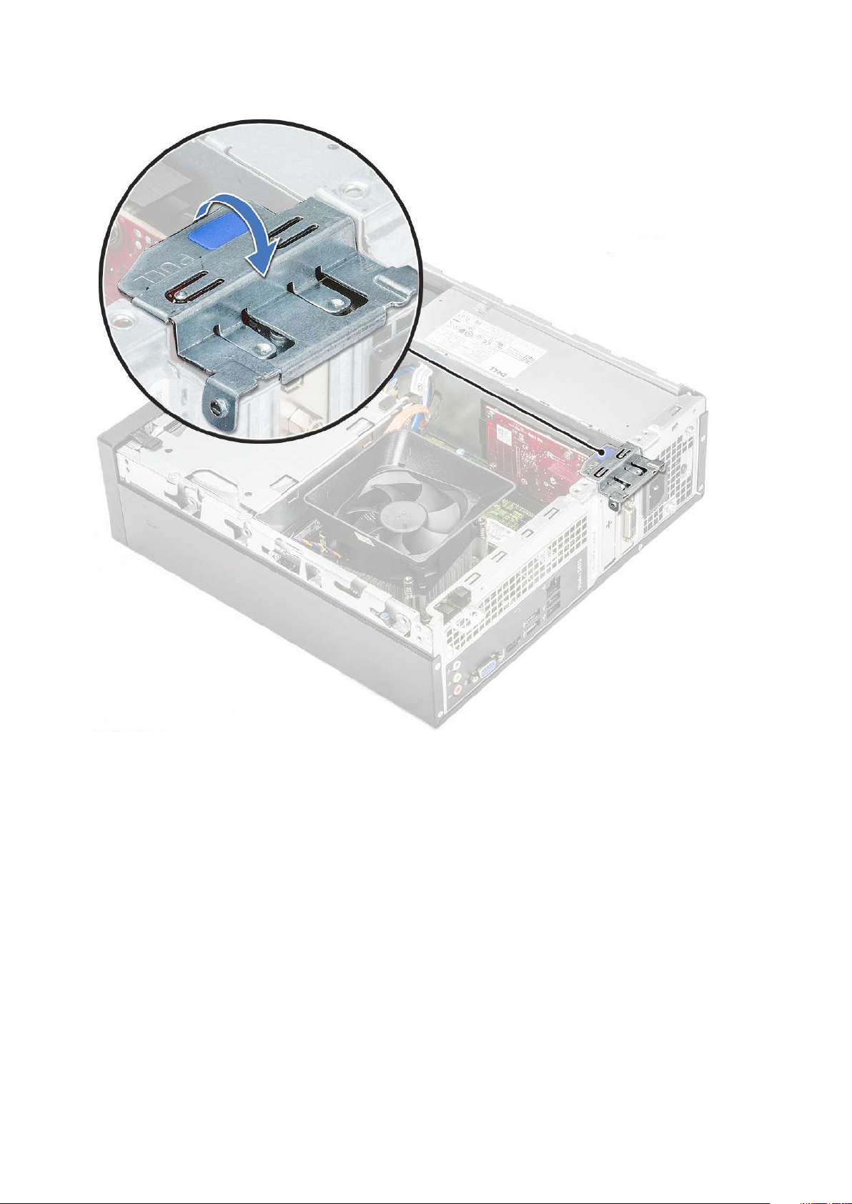
Installing PCIe expansion card in slot 1– optional
GUID-1FD8C8BB-5E57-4632-B82F-6BD5C3ED76B8
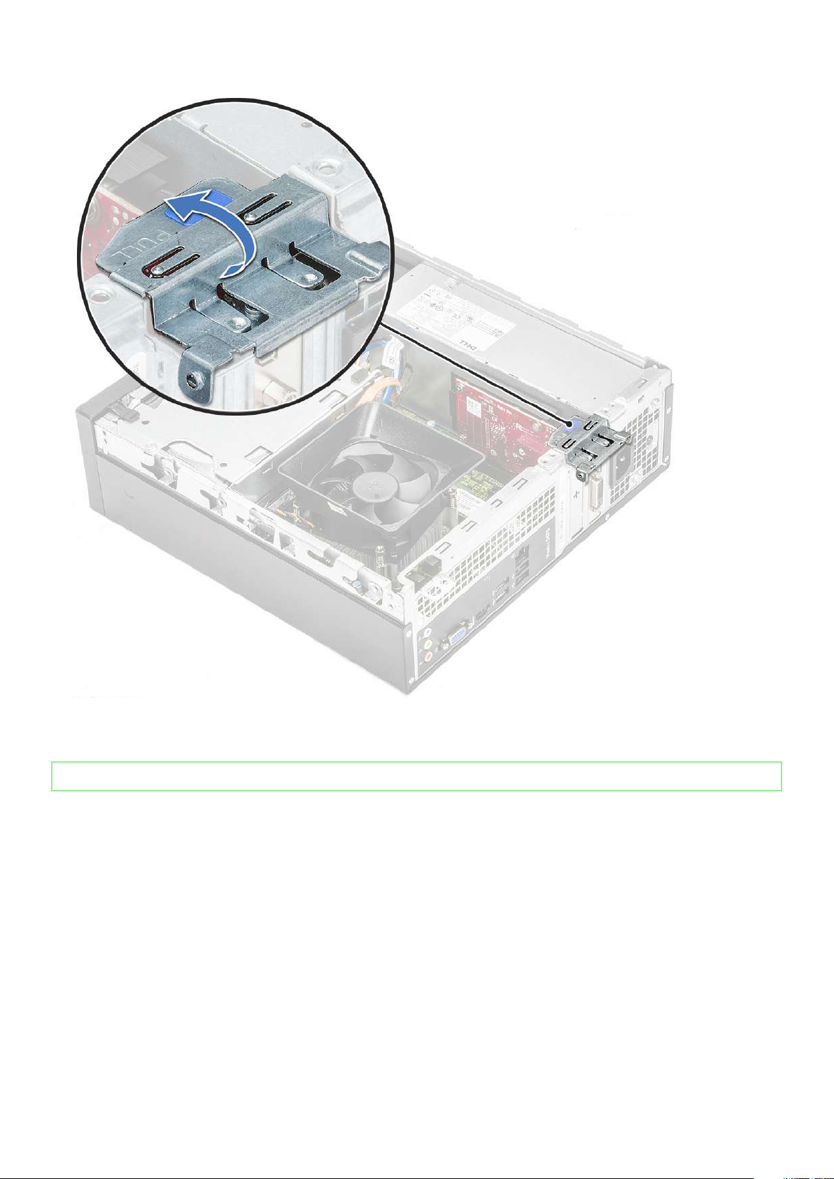
1. Pull the release latch to open .
28
Removing and installing components
Page 29

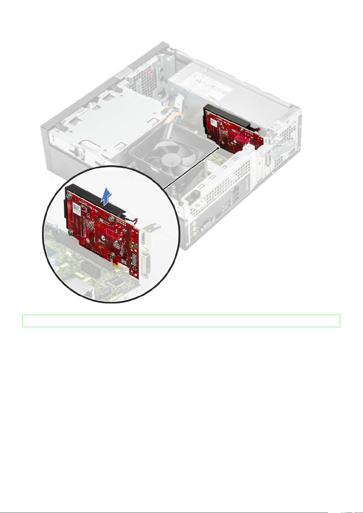
2. To remove the PCIe bracket as shown below, insert a flathead screwdriver in the hole of PCIe bracket [1], and repeatedly spin
screwdriver from 0-45 degrees to release the bracket [2].
Removing and installing components
29
Page 30

3. Insert the PCIe expansion card to the connector on the system board.
30
Removing and installing components
Page 31

4. Close the release latch.
5. Install the:
a) cover
6. Follow the procedure in After working inside your computer.
Identifier
Status Released
GUID-1183D437-9A73-41DC-895F-F1C2C5572202
3.5-inch hard drive chassis
GUID-1183D437-9A73-41DC-895F-F1C2C5572202
Identifier
Status Released
Removing the 3.5-inch hard drive chassis
GUID-C5C24213-AD5A-4A0C-8C8F-0A3151D2A02A
1. Follow the procedure in Before working inside your computer.
2. Remove the:
a) cover
GUID-C5C24213-AD5A-4A0C-8C8F-0A3151D2A02A
Removing and installing components
31
Page 32

b) front bezel
3. Disconnect the power and the data cables from the hard drive [1].
4. Remove the two 6-32xL6.35 screws that secure the 3.5-inch hard drive chassis to the drive bay [2].
5. Slide the 3.5-inch hard drive chassis and lift it from the system.
32
Removing and installing components
Page 33

Identifier GUID-51B06D73-6BA2-47AB-9DC6-8375EF6EB0BF
Status Released
Installing the 3.5-inch hard drive chassis
GUID-51B06D73-6BA2-47AB-9DC6-8375EF6EB0BF
1. Slide the 3.5-inch hard drive chassis into the drive bay.
Removing and installing components
33
Page 34

2. Replace the two 6-32xL3.5 screws to secure the 3.5-inch hard drive chassis to the computer [1].
3. Connect the data and power cables to the hard drive [2].
34
Removing and installing components
Page 35

4. Install:
a) front bezel
b) cover
5. Follow the procedures in After Working Inside Your Computer.
Identifier
Status Released
GUID-E483003F-ABE9-4947-A15F-DF6686A41352
3.5-inch hard drive
GUID-E483003F-ABE9-4947-A15F-DF6686A41352
Identifier
Status Released
Removing the 3.5-inch hard drive from the hard drive bracket
GUID-1279830A-4B0C-4AA7-9875-7BCC411DDE07
1. Follow the procedures in Before Working Inside Your Computer.
2. Remove:
a) cover
b) front bezel
GUID-1279830A-4B0C-4AA7-9875-7BCC411DDE07
Removing and installing components
35
Page 36

c) 3.5-inch hard drive chassis
3. Follow the steps to remove hard drive:
a) Remove the two 6-32xL3.6 screws that secure the hard drive to the bracket [1].
b) Slide and remove the hard drive from the bracket [2].
Identifier GUID-74A2D1C5-B615-4D6E-A23E-F2F4ECDC9558
Status Released
Installing the 3.5-inch hard drive into the hard drive bracket
GUID-74A2D1C5-B615-4D6E-A23E-F2F4ECDC9558
1. Slide the hard drive into the hard drive bracket [1].
2. Replace the two 6-32xL3.6 screws to secure the hard drive to the bracket [2].
3. Install:
a) 3.5-inch hard drive chassis
36
Removing and installing components
Page 37

b) front bezel
c) cover
4. Follow the procedure in After Working Inside Your Computer.
Identifier GUID-7139C960-2B26-4445-B232-D6D7EBBFA587
Status Released
Drive cage
GUID-7139C960-2B26-4445-B232-D6D7EBBFA587
Identifier GUID-CDA50E01-8EAC-4FCA-AAEA-4D158063E4B2
Status Released
Removing the drive cage
GUID-CDA50E01-8EAC-4FCA-AAEA-4D158063E4B2
1. Follow the procedure in Before working inside your computer.
2. Remove the:
a) cover
b) front bezel
c) cooling shroud
d) 3.5-inch hard drive chassis
3. Follow the steps to release the drive cage:
a) Remove the 6-32xL6.35 screw that secures the drive cage to the drive bay [1].
b) Press the blue tab to release the drive cage [2].
c) Slide the drive cage from the computer [3].
Removing and installing components
37
Page 38

4. Follow the steps to remove the drive cage:
a) Disconnect the power and the data cables from the optical drive [1].
b) Lift the optical drive cage from the system [2].
Identifier GUID-22E0D8B4-3AD1-411D-86C9-11D432346C10
Status Released
Installing the drive cage
GUID-22E0D8B4-3AD1-411D-86C9-11D432346C10
1. Place the drive cage in the chassis [1] and connect the data and power cables to the optical drive [2].
38
Removing and installing components
Page 39

2. Insert the drive cage into the slot until it clicks into place [1].
3. Replace the 6-32xL6.35 screw to secure the drive cage to the chassis [2].
Removing and installing components
39
Page 40

4. Install the:
a) 3.5-inch hard drive chassis
b) cooling shroud
c) front bezel
d) cover
5. Follow the procedure in After Working Inside Your Computer.
Identifier
Status Released
GUID-78527CE0-7E4A-4B32-A077-A2DAA34B0418
Optical drive
GUID-78527CE0-7E4A-4B32-A077-A2DAA34B0418
Identifier
Status Released
Removing the optical drive
GUID-B60C3226-F1CB-480B-89D1-FD3BA6B1E228
1. Follow the procedure in Before working inside your computer.
2. Remove the:
a) cover
b) front bezel
c) cooling shroud
d) 3.5-inch hard drive chassis
e) drive cage
3. Follow the steps to remove the bracket from the optical drive.
40
Removing and installing components
GUID-B60C3226-F1CB-480B-89D1-FD3BA6B1E228
Page 41

a) Remove the three M2x2 screws that secure the bracket to the optical drive [1].
b) Slide the optical drive from the bracket [2].
Identifier GUID-8D368588-ECF8-404B-99FF-D12B1BC0860F
Status Released
Installing the optical drive
GUID-8D368588-ECF8-404B-99FF-D12B1BC0860F
1. Slide the optical drive into the drive bay until it snaps [1].
2. Tighten the three M2x2 screws to secure the optical drive to the bracket [2].
3. Install the:
a) drive cage
b) 3.5-inch hard drive chassis
c) cooling shroud
Removing and installing components
41
Page 42

d) front bezel
e) cover
4. Follow the procedures in After working inside your computer.
Identifier GUID-C26DFCD2-CBE7-4C53-BDD1-618DB16026C4
Status Released
M.2 SATA SSD
GUID-C26DFCD2-CBE7-4C53-BDD1-618DB16026C4
Identifier GUID-F7018538-73CB-4866-B391-0E0FD6B607C0
Status Released
Removing M.2 SATA SSD
GUID-F7018538-73CB-4866-B391-0E0FD6B607C0
1. Follow the procedure in Before working inside your computer.
2. Remove the:
a) cover
3. To remove the M.2 SATA SSD:
a) Pull the blue tab that secures the M.2 SATA SSD to the system board [1].
b) Slide out the M.2 SATA SSD from the connector on the system board [2].
42
Removing and installing components
Page 43

Identifier GUID-A675B965-06A1-44B8-8CCC-33B114A1C157
Status Released
Installing M.2 SATA SSD
GUID-A675B965-06A1-44B8-8CCC-33B114A1C157
1. Insert the M.2 SATA SSD to the connector [1].
2. Press the blue tab to secure the M.2 SATA SSD [2].
Removing and installing components
43
Page 44

3. Install the:
a) cover
4. Follow the procedure in After working inside your computer.
Identifier
Status Released
GUID-CCAA203F-6E60-4861-BC9C-1EED5672FD0D
WLAN card
GUID-CCAA203F-6E60-4861-BC9C-1EED5672FD0D
Identifier
Status Released
Removing the WLAN card
GUID-002EFD07-0446-4ED8-A98B-37DA7FAA0612
1. Follow the procedure in Before working inside your computer.
2. Remove the:
a) cover
b) front bezel
44
Removing and installing components
GUID-002EFD07-0446-4ED8-A98B-37DA7FAA0612
Page 45

c) cooling shroud
d) 3.5-inch hard drive chassis
e) drive cage
3. Perform the following steps to remove the WLAN card from the computer:
a) Remove the M2L3.5 screw to release the plastic tab that secures the WLAN card to the computer [1, 2].
b) Disconnect the WLAN cables from the connectors on the WLAN card [3].
c) Remove the WLAN card from its connector on the system board [4].
Identifier GUID-3959438A-F195-4045-91A0-39F9C0CEDFCC
Status Released
Installing the WLAN card
GUID-3959438A-F195-4045-91A0-39F9C0CEDFCC
1. Insert the WLAN card to the connector on the system board [1].
2. Connect the WLAN cables to the connectors on the WLAN card[ 2] .
3. Place the plastic tab and tighten the M2x3.5 screw to secure the WLAN card to the system board [3].
Removing and installing components
45
Page 46

4. Install:
a) drive cage
b) 3.5-inch hard drive chassis
c) cooling shroud
d) front bezel
e) cover
5. Follow the procedure in After Working Inside Your Computer.
Identifier
Status Released
GUID-ED545F68-B25E-4947-9311-B6FAC5952525
Heat sink assembly
GUID-ED545F68-B25E-4947-9311-B6FAC5952525
Identifier
Status Released
Removing the heat sink assembly
GUID-AAAF0340-E497-4D36-9AB9-2D03BD9AA8D5
1. Follow the procedure in Before working inside your computer.
46
Removing and installing components
GUID-AAAF0340-E497-4D36-9AB9-2D03BD9AA8D5
Page 47

2. Remove the:
a) cover
b) cooling shroud
3. Follow the steps to remove the heat sink assembly:
a) Disconnect the heat sink assembly cable from the system board.
b) Remove the screws securing the heatsink assembly in a sequential order [1,2,3,4].
c) Lift the heat sink and remove it from the chassis.
Removing and installing components
47
Page 48

Identifier GUID-07C04835-60BF-4F55-8646-2A39C38FB3FD
Status Released
Installing the heat sink assembly
GUID-07C04835-60BF-4F55-8646-2A39C38FB3FD
1. Place the heat sink assembly in the slot by aligning with the screw holders.
2. Tighten the screws in a sequential order to secure the heat sink assembly to the system board [1,2,3,4].
48
Removing and installing components
Page 49

3. Connect the heat sink assembly cable to the connector on the system board.
Removing and installing components
49
Page 50

4. Install:
a) cooling shroud
b) cover
5. Follow the procedure in After Working Inside Your Computer.
Identifier
Status Released
GUID-B4BFAFB3-4A6A-47FD-A777-9CA7EF95C20B
Memory modules
GUID-B4BFAFB3-4A6A-47FD-A777-9CA7EF95C20B
Identifier
Status Released
Removing the memory module
GUID-0D6D66A9-4F4F-4CF9-8FB6-9955CF9ABB98
1. Follow the procedure in Before working inside your computer.
2. Remove the: .
a) cover
b) front bezel
c) 3.5-inch hard drive chassis
d) drive cage
e) Cooling shroud
3. To remove the front memory module:
a) Pull the clips securing the memory module until the memory module pops up [1].
GUID-0D6D66A9-4F4F-4CF9-8FB6-9955CF9ABB98
50
Removing and installing components
Page 51

b) Remove the memory module from the system board [2].
Identifier GUID-DE8AF270-AA21-48F0-AF5D-C2BAAB193D1A
Status Released
Installing the memory module
GUID-DE8AF270-AA21-48F0-AF5D-C2BAAB193D1A
1. Insert the memory module into the memory module socket until the clips secure the memory module.
Removing and installing components
51
Page 52

2. Install the: .
a) cooling shroud
b) drive cage
c) 3.5-inch hard drive chassis
d) front bezel
e) cover
3. Follow the procedure in After working inside your computer.
Identifier
Status Released
GUID-D35BA2D9-0E49-4AD7-A90D-A8139F114BAA
Power switch
GUID-D35BA2D9-0E49-4AD7-A90D-A8139F114BAA
Identifier
Status Released
Removing power switch
GUID-965E28EE-77A9-4CBC-84DA-29013BDB1943
1. Follow the procedure in Before working inside your computer.
52
Removing and installing components
GUID-965E28EE-77A9-4CBC-84DA-29013BDB1943
Page 53

2. Remove the:
a) cover
b) front bezel
c) 3.5-inch hard drive chassis
d) drive cage
3. To remove the power switch:
a) Remove the 6-32xL6.35 screw that secures the IO bracket [1] to the chassis and open the IO bracket[2].
b) Disconnect the power switch cable from the connector on the system board [1].
c) Press the power switch retention tabs [2] and pull the power switch out from the computer [3].
Removing and installing components
53
Page 54

Identifier GUID-C029358D-33F5-4A33-BC02-C40024F40841
Status Released
Installing the power switch
GUID-C029358D-33F5-4A33-BC02-C40024F40841
1. Slide the power switch module into the slot on the chassis until it clicks into place [1].
2. Connect the power switch cable to the connector on the system board [2].
54
Removing and installing components
Page 55

3. Push the IO bracket until it secures to the chassis [1].
4. Replace the 6-32xL6.35 screw to secure the IO bracket to the system [2].
Removing and installing components
55
Page 56

5. Install the:
a) drive cage
b) 3.5-inch hard drive chassis
c) front bezel
d) cover
6. Follow the procedure in After working inside your computer.
Identifier
Status Released
GUID-F8164337-4D5F-47F7-AEB2-E426D33BEB4B
Power supply unit
GUID-F8164337-4D5F-47F7-AEB2-E426D33BEB4B
Identifier
Status Released
Removing the power supply unit PSU
GUID-866F64E2-6B13-4A23-B28D-579386A20F67
1. Follow the procedure in Before working inside your computer.
2. Remove the:
a) cover
b) front bezel
c) cooling shroud
d) 3.5-inch hard drive chassis
e) drive cage
3. Perform the following steps to remove the power supply unit (PSU) from the computer:
a) Disconnect the PSU cables from the connectors on the system board [1, 3].
b) Unroute the PSU cables from the metal clips [2,,4].
GUID-866F64E2-6B13-4A23-B28D-579386A20F67
56
Removing and installing components
Page 57

4. Perform the following steps to remove the PSU:
a) Remove the three 6-32xL6.35 screws that secure the PSU [1].
b) Press the blue release tab to release the PSU [2].
Removing and installing components
57
Page 58

c) Slide and lift the PSU from the computer.
58
Removing and installing components
Page 59

Identifier GUID-928A874B-3531-4693-8B71-44D20F83892A
Status Released
Installing the power supply unit PSU
GUID-928A874B-3531-4693-8B71-44D20F83892A
1. Slide the PSU towards the back of the computer until it snaps into place.
Removing and installing components
59
Page 60

2. Replace the three 6-32xL6.35 screws to secure the power supply unit to the computer.
60
Removing and installing components
Page 61

3. Route the PSU cables through the placeholder.
4. Connect the PSU cables to their connectors on the system board.
Removing and installing components
61
Page 62

5. Install the:
a) drive cage
b) 3.5-inch hard drive chassis
c) cooling shroud
d) front bezel
e) cover
6. Follow the procedure in After Working Inside Your Computer.
Identifier
Status Released
GUID-B369D04D-3080-4AE8-912A-8F95B80E032D
Coin-cell battery
GUID-B369D04D-3080-4AE8-912A-8F95B80E032D
Identifier
Status Released
Removing the coin cell battery
GUID-CF3AB38C-5385-472E-AC9E-124C3FDCDA03
1. Follow the procedures in Before working inside your computer.
2. Remove the:
a) cover
62
Removing and installing components
GUID-CF3AB38C-5385-472E-AC9E-124C3FDCDA03
Page 63

b) front bezel
c) cooling shroud
d) 3.5-inch hard drive chassis
e) drive cage
3. Perform the following steps to remove the coin cell battery:
a) Press the coin cell battery on the open space of the socket using your finger so that the battery pops up from the socket [1].
b) Lift the coin cell battery out of the computer [2].
Identifier GUID-272B046A-B6AF-47B3-BF00-1568291C36FC
Status Released
Installing the coin cell battery
GUID-272B046A-B6AF-47B3-BF00-1568291C36FC
1. Place the coin cell battery in its slot on the system board [1] and press until it snaps in place [2]..
Removing and installing components
63
Page 64

2. Install the:
a) drive cage
b) 3.5-inch hard drive chassis
c) cooling shroud
d) front bezel
e) cover
3. Follow the procedures in After Working Inside Your Computer.
Identifier
Status Released
GUID-6D80D2E4-6FDC-4158-B13A-DD044EFA533C
Processor
GUID-6D80D2E4-6FDC-4158-B13A-DD044EFA533C
Identifier
Status Released
Removing the processor
GUID-8B64C840-647C-4BC8-9855-E1FB8A7EF345
1. Follow the procedure in Before working inside your computer.
64
Removing and installing components
GUID-8B64C840-647C-4BC8-9855-E1FB8A7EF345
Page 65

2. Remove the:
a) cover
b) cooling shroud
c) heatsink assembly
3. To remove the processor:
a) Press the release lever down and then move it outward to release it from the retention hook [1].
CAUTION: The processor socket pins are fragile and can be permanently damaged. Be careful not to bend the
pins in the processor socket when removing the processor out of the socket.
b) Lift the processor cover [2], remove the processor from the socket and place it in an antistatic bag [3].
Identifier GUID-DE671B53-9EB1-4B32-A29B-CEBFC8D29268
Status Released
Installing the processor
GUID-DE671B53-9EB1-4B32-A29B-CEBFC8D29268
1. Insert the processor in the processor socket. Ensure the processor is properly seated [1].
CAUTION:
the socket.
2. Lower the processor cover [2].
Do not use force to seat the processor. When the processor is positioned correctly, it engages easily into
Removing and installing components
65
Page 66

3. Press the release lever down and then move it inward to secure it with the retention hook [3].
4. Install the:
a) heat sink assembly
b) cooling shroud
c) cover
5. Follow the procedure in After working inside your computer.
Identifier
Status Released
GUID-57A55927-6E1E-400D-8732-224AC53A7435
System board
GUID-57A55927-6E1E-400D-8732-224AC53A7435
Identifier
Status Released
Removing the system board
GUID-E0DFA395-72BD-412A-9F1D-6E1110B68595
1. Follow the procedure in Before working inside your computer.
66
Removing and installing components
GUID-E0DFA395-72BD-412A-9F1D-6E1110B68595
Page 67

2. Remove the
a) cover
b) front bezel
c) 3.5-inch hard drive chassis
d) drive cage
e) memory module
f) cooling shroud
g) expansion card (optional)
h) M.2 SATA SSD
i) heat sink assembly
j) WLAN card
3. Follow the steps to open the IO bracket:
a) Remove the 6-32xL6.35 screw that secures the IO bracket to the chassis [1].
b) Pull the IO bracket to open the IO bracket [2].
4. Disconnect the following cables from the system board- ODD SATA cable and PSU cable [1], HDD SATA cable and HDD/ODD power
cable [2], power switch cable [3], and PSU cable [4]
Removing and installing components
67
Page 68

5. Follow the steps to remove the system board:
a) Remove the six 6-32xL6.35 screws that secure system board to the chassis.
68
Removing and installing components
Page 69

b) Pull the system board towards the front of the system.
Removing and installing components
69
Page 70

c) Lift the system board from the chassis.
70
Removing and installing components
Page 71

Identifier GUID-5F353059-74DE-422D-AC4D-2870AE5EAA60
Status Released
Installing the system board
GUID-5F353059-74DE-422D-AC4D-2870AE5EAA60
1. Insert the system board and ensure that ports are aligned to the holes on the back panel.
NOTE: Make sure to open the IO bracket before placing the system board in the system.
Removing and installing components 71
Page 72

2. Push the system board towards the rear side of the system.
72
Removing and installing components
Page 73

3. Replace the six 6-32xL6.35 screws to secure the system board.
Removing and installing components
73
Page 74

4. Connect the following cables to the system board- PSU cable [1], power switch cable [2], HDD SATA cable and HDD/ODD power
cable [3], ODD SATA cable and PSU cable [4].
74
Removing and installing components
Page 75

5. Close the IO bracket [1] and replace the 6-32xL6.35 screw to secure the IO bracket to the chassis [2].
Removing and installing components
75
Page 76

6. Install the:
a) heat sink assembly
b) WLAN card
c) expansion card (optional)
d) M.2 SATA SSD
e) drive cage
f) 3.5-inch hard drive chassis
g) cooling shroud
h) memory module
i) front bezel
j) cover
7. Follow the procedures in After Working Inside Your Computer.
Identifier
Status Released
GUID-2FA9BA72-E6AB-49CE-BFF3-9501CCC4FD18
TPM 2.0 installation
GUID-2FA9BA72-E6AB-49CE-BFF3-9501CCC4FD18
When you replace the system board for Windows 10 systems, the TPM 2.0 utility needs to be downloaded from Dell.com/support and
updated. The act of updating the TPM 2.0 is the customer's responsibility. Failure to update to TPM 2.0 does not cause any major
functionality issues with the system. Without TPM 2.0, some of the new, advanced security features of TPM 2.0 cannot be enabled
through Windows 10. At that point the customer can still update the system to TPM 2.0. While DSP technicians are encouraged to help
customers update to TPM 2.0 where possible, the risks of unavailable internet connection and restrictions have been taken into account
and as such this approach is flagged as a best effort basis.
Identifier
Status Released
Installing Dell TPM Update Utility for Windows or DOS
GUID-2C2FBB0C-C12A-4642-85C3-E92581A7641E
76
Removing and installing components
GUID-2C2FBB0C-C12A-4642-85C3-E92581A7641E
Page 77

1. Download the TPM.
a) Click Download File, to download the file.
b) When the File Download window appears, click Save to save the file to your hard drive.
2. Clear the TPM (See Notes 2, 3 and 4 below).
a) Before running the TPM update utility, clear the TPM Owner.
3. Disable TPM Auto Provisioning in Windows (See Note 4).
a) Boot to Windows.
b) Launch the PowerShell Command window in Administrator mode.
c) At the Powershell command prompt, execute the command: > Disable-TpmAutoProvisioning.
d) Confirm the following results:- AutoProvisioning: Disabled.
e) Reboot the system, to BIOS Setup by pressing F2.
f) Navigate to Security > TPM 1.2/2.0 Security .
g) Click the Clear checkbox and select Yes at the prompt to clear the TPM settings. (You can skip it if the item is grayed out).
h) Click Exit to save changes.
i) Reboot system to Windows.
j) Confirm the TPM is not owned. The TPM should no longer be automatically provisioned by Windows.
k) When the TPM update is finished, launch the PowerShell command in Administrator mode to re-enable the auto provisioning.
Enable-TpmAutoProvisioning.
l) Confirm the following results:- AutoProvisioning: Enabled.
4. Run the TPM update utility from Windows environment.
a) Browse to the location where you downloaded the file and double-click the new file.
b) Windows System will auto restart and update the TPM during the system startup.
c) When the TPM update is finished, the system will auto reboot to take effect.
5. Run the TPM update utility from DOS environment, if Legacy Boot mode (Non-Windows users).
a) Copy the downloaded file to a bootable DOS USB key.
b) Power on the system, then Press F12 key and Select USB Storage Device and Boot to DOS prompt.
c) Run the file by typing copied file name where the executable is located.
d) DOS system will auto restart and update the TPM during the system startup.
e) When the TPM update is finished, the system will auto reboot to take effect.
6. Run the BIOS update utility from DOS environment if UEFI Boot Mode (Non-Windows users).
Note 1:You will need to provide a bootable DOS USB key. This executable file does not create the DOS system files.
Note 2: If BitLocker is enabled on your system, please make sure you suspend BitLocker encryption before updating TPM on a
BitLocker enabled system.
Note 3: The TPM must be ON and Enabled in BIOS Setup, and the TPM must not be owned. If the TPM is owned, go to BIOS Setup
and clear the TPM before proceeding. You may need to run TPM.msc to re-initial the TPM under Windows OS.
Note 4: When the TPM ownership is cleared, some operating system will automatically take ownership of the TPM on the next boot
(TPM AutoProvisioning). This feature will need to be disabled in the OS to proceed with the update.
a) Copy the downloaded file to a bootable DOS USB key.
b) Power on the system, then go to BIOS Setup by pressing F2 and go to General > Boot Sequence > Boot List Option .
c) Change "UEFI" to "Legacy" of Boot List Option.
d) Click Apply, Exit to save changes and reboot system.
e) Press F12, then Select USB Storage Device and Boot to DOS prompt.
f) Run the file by typing copied file name where the executable is located.
g) When the TPM update is finished, the system will auto reboot to take effect.
h) Go to BIOS Setup by pressing F2 and go to General > Boot Sequence > Boot List Option.
i) Change "Legacy" to "UEFI" Boot Option.
j) Click Apply, Exit to save changes and reboot system.
Identifier
Status Released
GUID-F6B90CAA-F8BE-4D01-AE59-E4793ED160A0
Enabling firmware TPM in China
GUID-F6B90CAA-F8BE-4D01-AE59-E4793ED160A0
Removing and installing components
77
Page 78

Beginning May 2018, new systems with Windows 10 shipped to China region will be defaulted to firmware TPM (fTPM). The fTPM
improves and provides added security.
To check fTPM setting in BIOS Setup:
User can check the fTPM setting in the BIOS under the Security option, as shown below. The option lets you control whether the
Platform Trust Technology Feature (PTT) is visible to the operating system.
NOTE: The Enable Legacy Option ROMs option should be disabled to make the above setting.
78 Removing and installing components
Page 79

4
Identifier GUID-A27EB21E-BACD-423F-AC5C-DC2A051C2B48
Status Released
Troubleshooting
Identifier GUID-3A3576E1-EF1B-46DB-906F-9A07B70DACE5
Status Released
Enhanced Pre-Boot System Assessment — ePSA diagnostics
GUID-3A3576E1-EF1B-46DB-906F-9A07B70DACE5
The ePSA diagnostics (also known as system diagnostics) performs a complete check of your hardware. The ePSA is embedded with the
BIOS and is launched by the BIOS internally. The embedded system diagnostics provides a set of options for particular devices or device
groups allowing you to:
The ePSA diagnostics can be initiated by the FN+PWR buttons while powering on the computer.
• Run tests automatically or in an interactive mode
• Repeat tests
• Display or save test results
• Run thorough tests to introduce additional test options to provide extra information about the failed device(s)
• View status messages that inform you if tests are completed successfully
• View error messages that inform you of problems encountered during testing
NOTE:
terminal when the diagnostic tests are performed.
Identifier GUID-5FC0D943-B848-4BDC-9A26-78A5E88FDA45
Status Released
Some tests for specific devices require user interaction. Always ensure that you are present at the computer
Running the ePSA Diagnostics
GUID-5FC0D943-B848-4BDC-9A26-78A5E88FDA45
Invoke diagnostics boot by either of the methods that are suggested below:
1. Power on the computer.
2. As the computer boots, press the F12 key when the Dell logo is displayed.
3. In the boot menu screen, use Up/Down arrow key to select the Diagnostics option and then press Enter.
NOTE:
The diagnostics starts running the tests on all the detected devices.
4. Press the arrow in the lower-right corner to go to the page listing.
The detected items are listed and tested.
5. To run a diagnostic test on a specific device, press Esc and click Yes to stop the diagnostic test.
6. Select the device from the left pane and click Run Tests.
7. If there are any issues, error codes are displayed.
Note the error code and contact Dell.
The Enhanced Pre-boot System Assessment window displays, listing all devices detected in the computer.
Troubleshooting 79
Page 80

Identifier GUID-60C17CE6-CCEB-4E5B-B208-324CC3996AB5
Status Released
Diagnostics
GUID-60C17CE6-CCEB-4E5B-B208-324CC3996AB5
The computer POST (Power On Self Test) ensures that it meets the basic computer requirements and the hardware is working
appropriately before the boot process begins. If the computer passes the POST, the computer continues to start in a normal mode.
However, if the computer fails the POST, the computer emits a series of LED codes during the start-up. The system LED is integrated on
the Power button.
The following table shows different light patterns and what they indicate.
Table 3. Diagnostics
Amber Blinking Pattern Possible Problem Problem Description
2, 1 System board System board failure
2, 2 System board, PSU, or cabling System board, PSU, or cabling failure
2, 3 System board, memory, CPU System board, memory, or CPU failure
2, 4 CMOS (coin-cell) battery Coin-cell battery failure
2, 5 BIOS Corrupt BIOS. Recovery image is not found
or is invalid during auto BIOS recovery
process.
2, 6 CPU CPU configuration error or CPU failure
2, 7 Memory Memory failure
3, 1 PCI/video PCI or video card / chip failure
3, 2 Storage/USB Storage and USB configuration error or
failure
3, 3 Memory No memory detected
3, 4 System board System board error
3, 5 Memory Memory configuration error, incompatible
memory, or invalid memory configuration
3, 6 BIOS Recovery image not found
3, 7 BIOS Recovery image found but invalid
Identifier GUID-6C8A4AD6-8487-434C-8EF5-5E43DA8BAF61
Status Released
Diagnostic error messages
GUID-6C8A4AD6-8487-434C-8EF5-5E43DA8BAF61
Table 4. Diagnostic error messages
Error messages Description
AUXILIARY DEVICE FAILURE
BAD COMMAND OR FILE NAME
CACHE DISABLED DUE TO FAILURE
CD DRIVE CONTROLLER FAILURE
80 Troubleshooting
The touchpad or external mouse may be faulty. For an external
mouse, check the cable connection. Enable the Pointing Device
option in the System Setup program.
Ensure that you have spelled the command correctly, put spaces in
the proper place, and used the correct path name.
The primary cache internal to the microprocessor has failed.
Contact Dell
The optical drive does not respond to commands from the
computer.
Page 81

Error messages Description
DATA ERROR
DECREASING AVAILABLE MEMORY
DISK C: FAILED INITIALIZATION
DRIVE NOT READY
ERROR READING PCMCIA CARD
EXTENDED MEMORY SIZE HAS CHANGED
THE FILE BEING COPIED IS TOO LARGE FOR THE
DESTINATION DRIVE
A FILENAME CANNOT CONTAIN ANY OF THE FOLLOWING
CHARACTERS: \ / : * ? " < > | -
GATE A20 FAILURE
GENERAL FAILURE
HARD-DISK DRIVE CONFIGURATION ERROR
HARD-DISK DRIVE CONTROLLER FAILURE 0
HARD-DISK DRIVE FAILURE
HARD-DISK DRIVE READ FAILURE
INSERT BOOTABLE MEDIA
INVALID CONFIGURATION INFORMATION-PLEASE RUN
SYSTEM SETUP PROGRAM
KEYBOARD CLOCK LINE FAILURE
The hard drive cannot read the data.
One or more memory modules may be faulty or improperly seated.
Reinstall the memory modules or, if necessary, replace them.
The hard drive failed initialization. Run the hard drive tests in Dell
Diagnostics.
The operation requires a hard drive in the bay before it can
continue. Install a hard drive in the hard drive bay.
The computer cannot identify the ExpressCard. Reinsert the card
or try another card.
The amount of memory recorded in non-volatile memory (NVRAM)
does not match the memory module installed in the computer.
Restart the computer. If the error appears again, Contact Dell
The file that you are trying to copy is too large to fit on the disk, or
the disk is full. Try copying the file to a different disk or use a larger
capacity disk.
Do not use these characters in filenames.
A memory module may be loose. Reinstall the memory module or, if
necessary, replace it.
The operating system is unable to carry out the command. The
message is usually followed by specific information. For example,
Printer out of paper. Take the appropriate
action.
The computer cannot identify the drive type. Shut down the
computer, remove the hard drive, and boot the computer from an
optical drive. Then, shut down the computer, reinstall the hard
drive, and restart the computer. Run the Hard Disk Drive tests in
Dell Diagnostics.
The hard drive does not respond to commands from the computer.
Shut down the computer, remove the hard drive, and boot the
computer from an optical drive. Then, shut down the computer,
reinstall the hard drive, and restart the computer. If the problem
persists, try another drive. Run the Hard Disk Drive tests in Dell
Diagnostics.
The hard drive may be defective. Shut down the computer, remove
the hard drive, and boot the computer from an optical. Then, shut
down the computer, reinstall the hard drive, and restart the
computer. If the problem persists, try another drive. Run the Hard
Disk Drive tests in Dell Diagnostics.
The operating system is trying to boot to non-bootable media, such
as an optical drive. Insert bootable media.
The system configuration information does not match the
hardware configuration. The message is most likely to occur after a
memory module is installed. Correct the appropriate options in the
system setup program.
For external keyboards, check the cable connection. Run the
Keyboard Controller test in Dell Diagnostics.
Troubleshooting 81
Page 82

Error messages Description
KEYBOARD CONTROLLER FAILURE
KEYBOARD DATA LINE FAILURE
KEYBOARD STUCK KEY FAILURE
LICENSED CONTENT IS NOT ACCESSIBLE IN
MEDIADIRECT
MEMORY ADDRESS LINE FAILURE AT ADDRESS, READ
VALUE EXPECTING VALUE
MEMORY ALLOCATION ERROR
MEMORY DOUBLE WORD LOGIC FAILURE AT ADDRESS,
READ VALUE EXPECTING VALUE
MEMORY ODD/EVEN LOGIC FAILURE AT ADDRESS, READ
VALUE EXPECTING VALUE
MEMORY WRITE/READ FAILURE AT ADDRESS, READ
VALUE EXPECTING VALUE
NO BOOT DEVICE AVAILABLE
NO BOOT SECTOR ON HARD DRIVE
NO TIMER TICK INTERRUPT
NOT ENOUGH MEMORY OR RESOURCES. EXIT SOME
PROGRAMS AND TRY AGAIN
OPERATING SYSTEM NOT FOUND
OPTIONAL ROM BAD CHECKSUM
SECTOR NOT FOUND
SEEK ERROR
SHUTDOWN FAILURE
TIME-OF-DAY CLOCK LOST POWER
For external keyboards, check the cable connection. Restart the
computer, and avoid touching the keyboard or the mouse during
the boot routine. Run the Keyboard Controller test in Dell
Diagnostics.
For external keyboards, check the cable connection. Run the
Keyboard Controller test in Dell Diagnostics.
For external keyboards or keypads, check the cable connection.
Restart the computer, and avoid touching the keyboard or keys
during the boot routine. Run the Stuck Key test in Dell
Diagnostics.
Dell MediaDirect cannot verify the Digital Rights Management
(DRM) restrictions on the file, so the file cannot be played.
A memory module may be faulty or improperly seated. Reinstall the
memory module or, if necessary, replace it.
The software you are attempting to run is conflicting with the
operating system, another program, or a utility. Shut down the
computer, wait for 30 seconds, and then restart it. Run the
program again. If the error message still appears, see the software
documentation.
A memory module may be faulty or improperly seated. Reinstall the
memory module or, if necessary, replace it.
A memory module may be faulty or improperly seated. Reinstall the
memory module or, if necessary, replace it.
A memory module may be faulty or improperly seated. Reinstall the
memory module or, if necessary, replace it.
The computer cannot find the hard drive. If the hard drive is your
boot device, ensure that the drive is installed, properly seated, and
partitioned as a boot device.
The operating system may be corrupted, Contact Dell.
A chip on the system board may be malfunctioning. Run the
System Set tests in Dell Diagnostics.
You have too many programs open. Close all windows and open the
program that you want to use.
Reinstall the operating system. If the problem persists, Contact
Dell.
The optional ROM has failed. Contact Dell.
The operating system cannot locate a sector on the hard drive. You
may have a defective sector or corrupted File Allocation Table
(FAT) on the hard drive. Run the Windows error-checking utility to
check the file structure on the hard drive. See Windows Help and
Support for instructions (click Start > Help and Support). If a
large number of sectors are defective, back up the data (if
possible), and then format the hard drive.
The operating system cannot find a specific track on the hard
drive.
A chip on the system board may be malfunctioning. Run the
System Set tests in Dell Diagnostics. If the message reappears,
Contact Dell.
System configuration settings are corrupted. Connect your
computer to an electrical outlet to charge the battery. If the
problem persists, try to restore the data by entering the System
Setup program, then immediately exit the program. If the message
reappears, Contact Dell.
82 Troubleshooting
Page 83

Error messages Description
TIME-OF-DAY CLOCK STOPPED
TIME-OF-DAY NOT SET-PLEASE RUN THE SYSTEM SETUP
PROGRAM
TIMER CHIP COUNTER 2 FAILED
UNEXPECTED INTERRUPT IN PROTECTED MODE
X:\ IS NOT ACCESSIBLE. THE DEVICE IS NOT READY
Identifier GUID-602C06E2-7AF7-4CD3-9446-4F5A4064DC18
Status Released
The reserve battery that supports the system configuration
settings may require recharging. Connect your computer to an
electrical outlet to charge the battery. If the problem persists,
Contact Dell.
The time or date stored in the system setup program does not
match the system clock. Correct the settings for the Date and
Time options.
A chip on the system board may be malfunctioning. Run the
System Set tests in Dell Diagnostics.
The keyboard controller may be malfunctioning, or a memory
module may be loose. Run the System Memory tests and the
Keyboard Controller test in Dell Diagnostics or Contact Dell.
Insert a disk into the drive and try again.
System error messages
GUID-602C06E2-7AF7-4CD3-9446-4F5A4064DC18
Table 5. System error messages
System message Description
Alert! Previous attempts at booting this system
have failed at checkpoint [nnnn]. For help in
resolving this problem, please note this
checkpoint and contact Dell Technical Support
CMOS checksum error
CPU fan failure
System fan failure
Hard-disk drive failure
Keyboard failure
No boot device available
The computer failed to complete the boot routine three
consecutive times for the same error.
RTC is reset, BIOS Setup default has been loaded.
CPU fan has failed.
System fan has failed.
Possible hard disk drive failure during POST.
Keyboard failure or loose cable. If reseating the cable does not
solve the problem, replace the keyboard.
No bootable partition on hard disk drive, the hard disk drive cable is
loose, or no bootable device exists.
• If the hard drive is your boot device, ensure that the cables are
connected and that the drive is installed properly and
partitioned as a boot device.
• Enter system setup and ensure that the boot sequence
information is correct.
No timer tick interrupt
NOTICE - Hard Drive SELF MONITORING SYSTEM has
reported that a parameter has exceeded its
normal operating range. Dell recommends that
you back up your data regularly. A parameter
out of range may or may not indicate a
potential hard drive problem
A chip on the system board might be malfunctioning or
motherboard failure.
S.M.A.R.T error, possible hard disk drive failure.
Troubleshooting 83
Page 84

Identifier GUID-BE16C181-0959-44C3-B434-E44A0A602A4C
Status Released
Topics:
• Contacting Dell
5
Getting help
Identifier
Status Released
GUID-7A3627F9-0363-4515-A1D4-1B7878F4B8C4
Contacting Dell
GUID-7A3627F9-0363-4515-A1D4-1B7878F4B8C4
NOTE: If you do not have an active Internet connection, you can find contact information on your purchase invoice,
packing slip, bill, or Dell product catalog.
Dell provides several online and telephone-based support and service options. Availability varies by country and product, and some services
may not be available in your area. To contact Dell for sales, technical support, or customer service issues:
1. Go to Dell.com/support.
2. Select your support category.
3. Verify your country or region in the Choose a Country/Region drop-down list at the bottom of the page.
4. Select the appropriate service or support link based on your need.
84 Getting help
 Loading...