

Page 1

Dell Latitude 5520/E5520/E5520m Owner's Manual
Regulatory Model: P16G
Regulatory Type: P16G001
Page 2

Notes, Cautions, and Warnings
NOTE: A NOTE indicates important information that helps you make better use of your computer.
CAUTION: A CAUTION indicates potential damage to hardware or loss of data if instructions are not followed.
WARNING: A WARNING indicates a potential for property damage, personal injury, or death.
Page 3

Contents
Notes, Cautions, and Warnings...................................................................................................2
1 Working on Your Computer.......................................................................................................7
Before Working Inside Your Computer.....................................................................................................................7
Recommended Tools................................................................................................................................................8
Turning Off Your Computer.......................................................................................................................................8
After Working Inside Your Computer........................................................................................................................9
2 Battery.........................................................................................................................................11
Removing the Battery.............................................................................................................................................11
Installing the Battery..............................................................................................................................................11
3 PC Card.......................................................................................................................................13
Removing the PC Card............................................................................................................................................13
Installing the PC Card.............................................................................................................................................14
4 Secure Digital (SD) Card..........................................................................................................15
Removing The Secure Digital (SD) Card.................................................................................................................15
Installing The Secure Digital (SD) Card..................................................................................................................15
5 Subscriber Identity Module (SIM) Card................................................................................17
Removing the Subscriber Identity Module (SIM) Card...........................................................................................17
Installing the Subscriber Identity Module (SIM) Card............................................................................................17
6 ExpressCard...............................................................................................................................19
Removing the ExpressCard.....................................................................................................................................19
Installing the ExpressCard......................................................................................................................................19
7 Back Panel.................................................................................................................................21
Removing the Back Panel.......................................................................................................................................21
Installing the Back Panel........................................................................................................................................21
8 Keyboard Trim............................................................................................................................23
Removing the Keyboard Trim..................................................................................................................................23
Installing the Keyboard Trim...................................................................................................................................24
9 Keyboard.....................................................................................................................................25
Removing the Keyboard..........................................................................................................................................25
Page 4

Installing the Keyboard...........................................................................................................................................27
10 Optical Drive.............................................................................................................................29
Removing the Optical Drive....................................................................................................................................29
Installing the Optical Drive.....................................................................................................................................30
11 Hard Drive.................................................................................................................................31
Removing the Hard Drive........................................................................................................................................31
Installing the Hard Drive.........................................................................................................................................32
12 Wireless Local Area Network (WLAN) Card......................................................................33
Removing the Wireless Local Area Network (WLAN) Card...................................................................................33
Installing The Wireless Local Area Network (WLAN) Card...................................................................................34
13 Wireless Wide Area Network (WWAN) Card....................................................................35
Removing the Wireless Wide Area Network (WWAN) Card..................................................................................35
Installing The Wireless Wide Area Network (WWAN) Card..................................................................................36
14 Memory.....................................................................................................................................37
Removing the Memory Module..............................................................................................................................37
Installing the Memory Module................................................................................................................................37
15 CPU Door..................................................................................................................................39
Removing the CPU Door..........................................................................................................................................39
Installing the CPU Door...........................................................................................................................................39
16 Heat Sink...................................................................................................................................41
Removing the Heat Sink..........................................................................................................................................41
Installing the Heat Sink...........................................................................................................................................41
17 Processor.................................................................................................................................43
Removing the Processor.........................................................................................................................................43
Installing the Processor..........................................................................................................................................43
18 Palm Rest..................................................................................................................................45
Removing the Palm Rest.........................................................................................................................................45
Installing the Palm Rest..........................................................................................................................................47
19 ExpressCard/Smart Card/PCMCIA Module........................................................................49
Removing the ExpressCard/Smart Card/PCMCIA Module.....................................................................................49
Installing the ExpressCard/Smart Card/PCMCIA Module......................................................................................50
20 Bluetooth Card.........................................................................................................................51
Page 5

Removing the Bluetooth Card.................................................................................................................................51
Installing the Bluetooth Card..................................................................................................................................52
21 Display Assembly....................................................................................................................53
Removing the Display Assembly.............................................................................................................................53
Installing the Display Assembly..............................................................................................................................55
22 Brackets....................................................................................................................................57
Removing the Support Brackets.............................................................................................................................57
Installing the Support Brackets..............................................................................................................................59
23 Modem Card.............................................................................................................................61
Removing the Modem Card....................................................................................................................................61
Installing the Modem Card.....................................................................................................................................62
24 Audio Board.............................................................................................................................63
Removing the Audio Board.....................................................................................................................................63
Installing the Audio Board......................................................................................................................................64
25 System Board...........................................................................................................................65
Removing the System Board...................................................................................................................................65
Installing the System Board....................................................................................................................................67
26 Coin-Cell Battery.....................................................................................................................69
Removing the Coin-Cell Battery..............................................................................................................................69
Installing the Coin-Cell Battery...............................................................................................................................69
27 Input/Output Panel..................................................................................................................71
Removing the Input/Output (I/O) Panel...................................................................................................................71
Installing the Input/Output (I/O) Panel....................................................................................................................72
28 Power Connector....................................................................................................................73
Removing the Power Connector.............................................................................................................................73
Installing the Power Connector..............................................................................................................................74
29 Modem Connector..................................................................................................................75
Removing the Modem Connector...........................................................................................................................75
Installing the Modem Connector............................................................................................................................75
30 Thermal Fan..............................................................................................................................77
Removing the Thermal Fan.....................................................................................................................................77
Installing the Thermal Fan......................................................................................................................................78
Page 6

31 Speaker.....................................................................................................................................81
Removing the Speakers..........................................................................................................................................81
Installing the Speakers...........................................................................................................................................82
32 Display Bezel............................................................................................................................85
Removing the Display Bezel...................................................................................................................................85
Installing the Display Bezel.....................................................................................................................................86
33 Display Panel...........................................................................................................................87
Removing the Display Panel...................................................................................................................................87
Installing the Display Panel....................................................................................................................................88
34 Display Hinges.........................................................................................................................89
Removing the Display Hinges.................................................................................................................................89
Installing the Display Hinges..................................................................................................................................91
35 Camera......................................................................................................................................93
Removing the Camera.............................................................................................................................................93
Installing the Camera..............................................................................................................................................94
36 Specifications..........................................................................................................................95
Technical Specifications........................................................................................................................................95
37 System Setup.........................................................................................................................101
Overview ..............................................................................................................................................................101
Entering System Setup..........................................................................................................................................101
System Setup Options...........................................................................................................................................101
38 Diagnostics.............................................................................................................................109
Diagnostics...........................................................................................................................................................109
Device Status LightsBattery Status LightsBattery Charge and HealthKeyboard Status Lights....................109
39 Contacting Dell......................................................................................................................111
Contacting Dell.....................................................................................................................................................111
Page 7
Working on Your Computer
Before Working Inside Your Computer
Use the following safety guidelines to help protect your computer from potential damage and to help to ensure your
personal safety. Unless otherwise noted, each procedure included in this document assumes that the following
conditions exist:
• You have performed the steps in Working on Your Computer.
• You have read the safety information that shipped with your computer.
• A component can be replaced or--if purchased separately--installed by performing the removal procedure in
reverse order.
WARNING: Before working inside your computer, read the safety information that shipped with your computer. For
additional safety best practices information, see the Regulatory Compliance Homepage at www.dell.com/
regulatory_compliance.
CAUTION: Many repairs may only be done by a certified service technician. You should only perform
troubleshooting and simple repairs as authorized in your product documentation, or as directed by the online or
telephone service and support team. Damage due to servicing that is not authorized by Dell is not covered by your
warranty. Read and follow the safety instructions that came with the product.
CAUTION: To avoid electrostatic discharge, ground yourself by using a wrist grounding strap or by periodically
touching an unpainted metal surface, such as a connector on the back of the computer.
1
CAUTION: Handle components and cards with care. Do not touch the components or contacts on a card. Hold a
card by its edges or by its metal mounting bracket. Hold a component such as a processor by its edges, not by its
pins.
CAUTION: When you disconnect a cable, pull on its connector or on its pull-tab, not on the cable itself. Some
cables have connectors with locking tabs; if you are disconnecting this type of cable, press in on the locking tabs
before you disconnect the cable. As you pull connectors apart, keep them evenly aligned to avoid bending any
connector pins. Also, before you connect a cable, ensure that both connectors are correctly oriented and aligned.
NOTE: The color of your computer and certain components may appear differently than shown in this document.
To avoid damaging your computer, perform the following steps before you begin working inside the computer.
1. Ensure that your work surface is flat and clean to prevent the computer cover from being scratched.
2. Turn off your computer (see Turning Off Your Computer).
3. If the computer is connected to a docking device (docked) such as the optional Media Base or Battery Slice,
undock it.
CAUTION: To disconnect a network cable, first unplug the cable from your computer and then unplug the
cable from the network device.
4. Disconnect all network cables from the computer.
5. Disconnect your computer and all attached devices from their electrical outlets.
7
Page 8
6. Close the display and turn the computer upside-down on a flat work surface.
NOTE: To avoid damaging the system board, you must remove the main battery before you service the
computer.
7. Remove the main battery (see Battery).
8. Turn the computer top-side up.
9. Open the display.
10. Press the power button to ground the system board.
CAUTION: To guard against electrical shock, always unplug your computer from the electrical outlet before
opening the display.
CAUTION: Before touching anything inside your computer, ground yourself by touching an unpainted metal
surface, such as the metal at the back of the computer. While you work, periodically touch an unpainted metal
surface to dissipate static electricity, which could harm internal components.
11. Remove any installed ExpressCards or Smart Cards from the appropriate slots.
Recommended Tools
The procedures in this document may require the following tools:
• Small flat-blade screwdriver
• #0 Phillips screwdriver
• #1 Phillips screwdriver
• Small plastic scribe
• Flash BIOS update program CD
Turning Off Your Computer
CAUTION: To avoid losing data, save and close all open files and exit all open programs before you turn off your
computer.
1. Shut down the operating system:
– In Windows Vista :
Click Start , then click the arrow in the lower-right corner of the Start menu as shown below, and then
click Shut Down.
– In Windows XP:
Click Start → Turn Off Computer → Turn Off . The computer turns off after the operating system shutdown
process is complete.
2. Ensure that the computer and all attached devices are turned off. If your computer and attached devices did not
automatically turn off when you shut down your operating system, press and hold the power button for about 4
seconds to turn them off.
8
Page 9

After Working Inside Your Computer
After you complete any replacement procedure, ensure you connect any external devices, cards, and cables before
turning on your computer.
CAUTION: To avoid damage to the computer, use only the battery designed for this particular Dell computer. Do not
use batteries designed for other Dell computers.
1. Connect any external devices, such as a port replicator, battery slice, or media base, and replace any cards, such
as an ExpressCard.
2. Connect any telephone or network cables to your computer.
CAUTION: To connect a network cable, first plug the cable into the network device and then plug it into the
computer.
3. Replace the battery.
4. Connect your computer and all attached devices to their electrical outlets.
5. Turn on your computer.
9
Page 10

10
Page 11
Battery
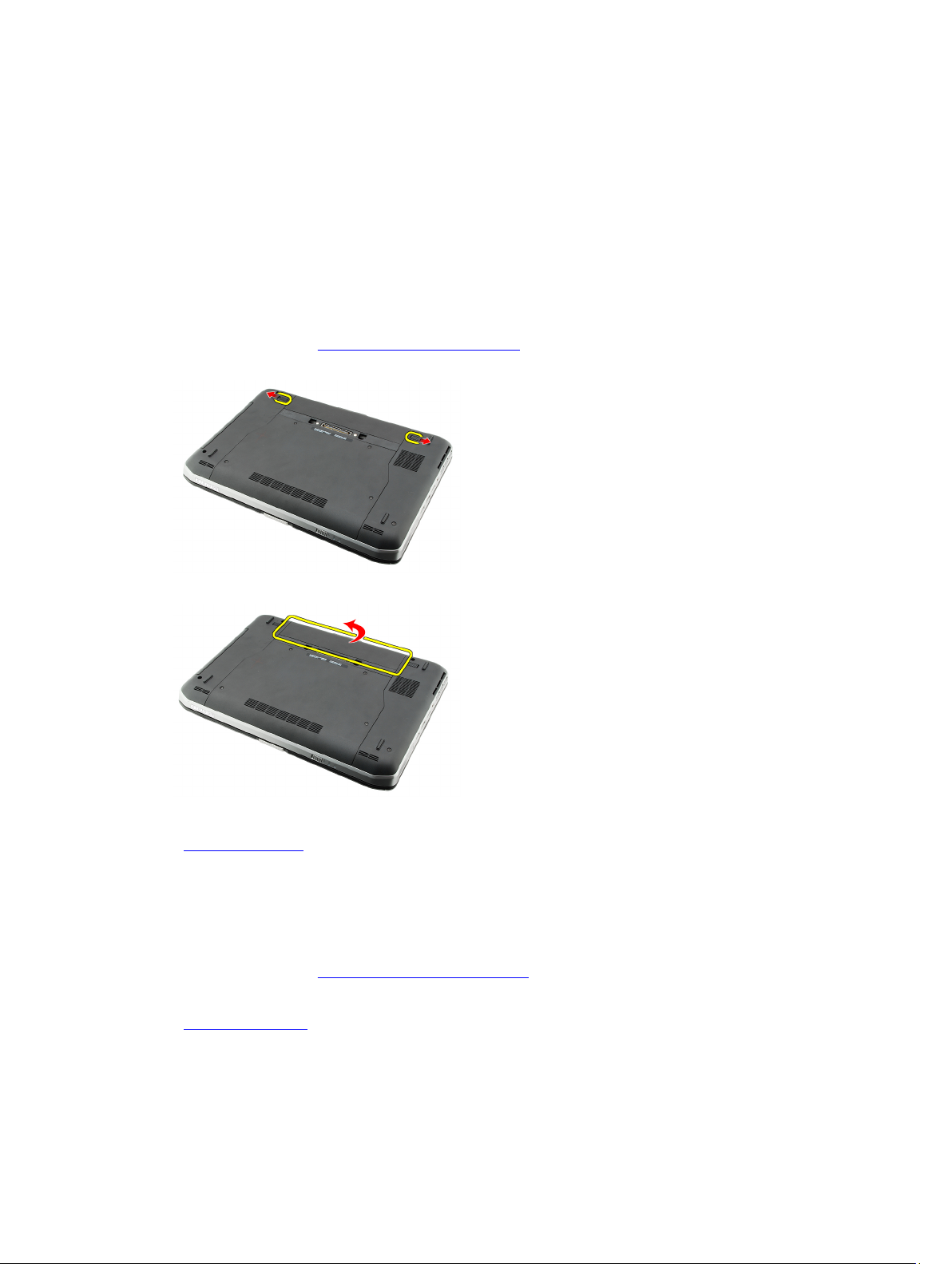
Removing the Battery
1. Follow the procedures in Before Working On Your Computer.
2. Slide the release latches to unlock the battery.
3. Remove the battery from the computer.
2
Related Links
Installing the Battery
Installing the Battery
1. Slide the battery back into the computer.
The release latches automatically click into the lock position.
2. Follow the procedures in After Working Inside Your Computer.
Related Links
Removing the Battery
11
Page 12

12
Page 13
PC Card
Removing the PC Card
1. Follow the procedures in Before Working On Your Computer.
2. Press in on the PC latch to release the latch.
3. Press in on the PC latch to release the PC card.
3
4. Slide the PC card out of the computer.
Related Links
Installing the PC Card
13
Page 14

Installing the PC Card
1. Push the PC latch to lock it.
2. Push the PC card to its slot until it clicks.
3. Follow the procedures in After Working Inside Your Computer.
Related Links
Removing the PC Card
14
Page 15
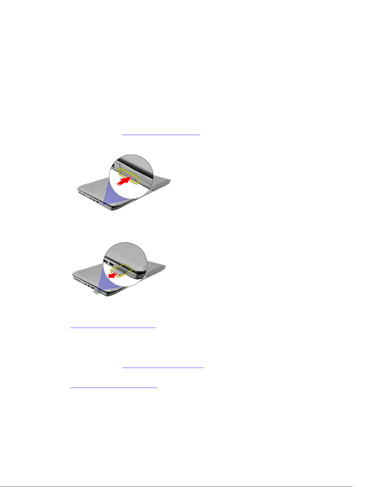
Secure Digital (SD) Card
Removing The Secure Digital (SD) Card
1. Follow the procedures in Before Working On Your Computer.
2. Push in on the SD card.
3. Slide the SD card out of the computer.
4
Related Links
Installing The Secure Digital (SD) Card
Installing The Secure Digital (SD) Card
1. Slide the SD card into its slot until it clicks into place.
2. Follow the procedures in After Working Inside Your Computer.
Related Links
Removing The Secure Digital (SD) Card
15
Page 16

16
Page 17
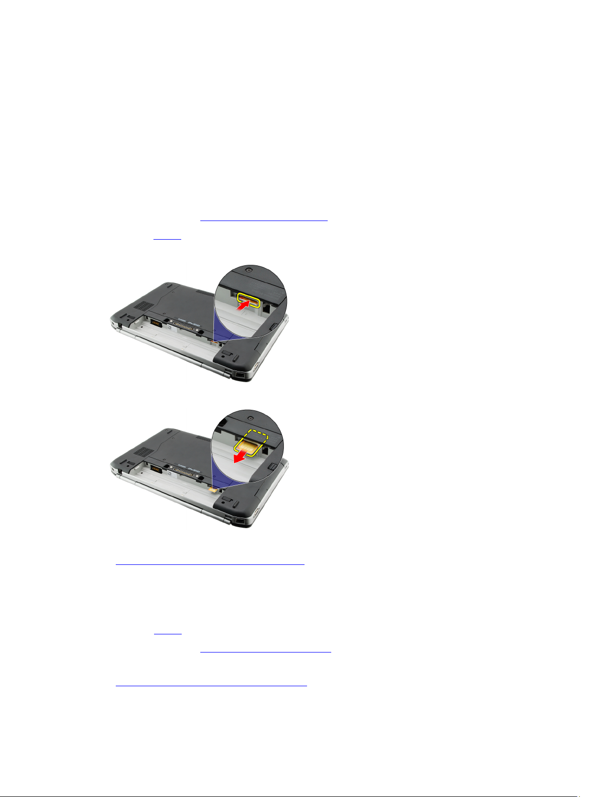
Subscriber Identity Module (SIM) Card
Removing the Subscriber Identity Module (SIM) Card
1. Follow the procedures in Before Working On Your Computer.
2. Remove the battery.
3. Press and release the SIM card located on the battery wall.
4. Slide the SIM card from the computer.
5
Related Links
Installing the Subscriber Identity Module (SIM) Card
Installing the Subscriber Identity Module (SIM) Card
1. Insert the SIM card into the slot.
2. Replace the battery.
3. Follow the procedures in After Working Inside Your Computer.
Related Links
Removing the Subscriber Identity Module (SIM) Card
17
Page 18

18
Page 19
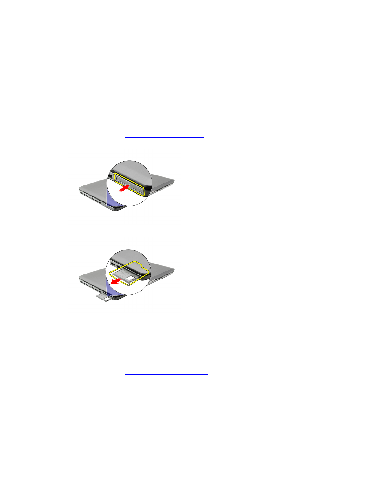
ExpressCard
Removing the ExpressCard
1. Follow the procedures in Before Working On Your Computer.
2. Push in on the ExpressCard.
3. Slide the ExpressCard out of the computer.
6
Related Links
Installing the ExpressCard
Installing the ExpressCard
1. Insert the ExpressCard into the slot until it clicks into place.
2. Follow the procedures in After Working Inside Your Computer.
Related Links
Removing the ExpressCard
19
Page 20

20
Page 21
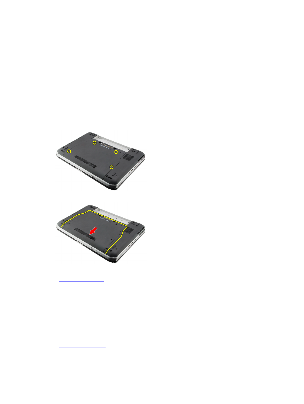
Back Panel
Removing the Back Panel
1. Follow the procedures in Before Working On Your Computer.
2. Remove the battery.
3. Remove the screws that secure the back panel.
4. Slide and remove the back panel toward the front of the computer .
7
Related Links
Installing the Back Panel
Installing the Back Panel
1. Slide the back panel towards the back of the computer.
2. Tighten the screws to secure the back panel.
3. Replace the battery.
4. Follow the procedures in After Working Inside Your Computer.
Related Links
Removing the Back Panel
21
Page 22

22
Page 23
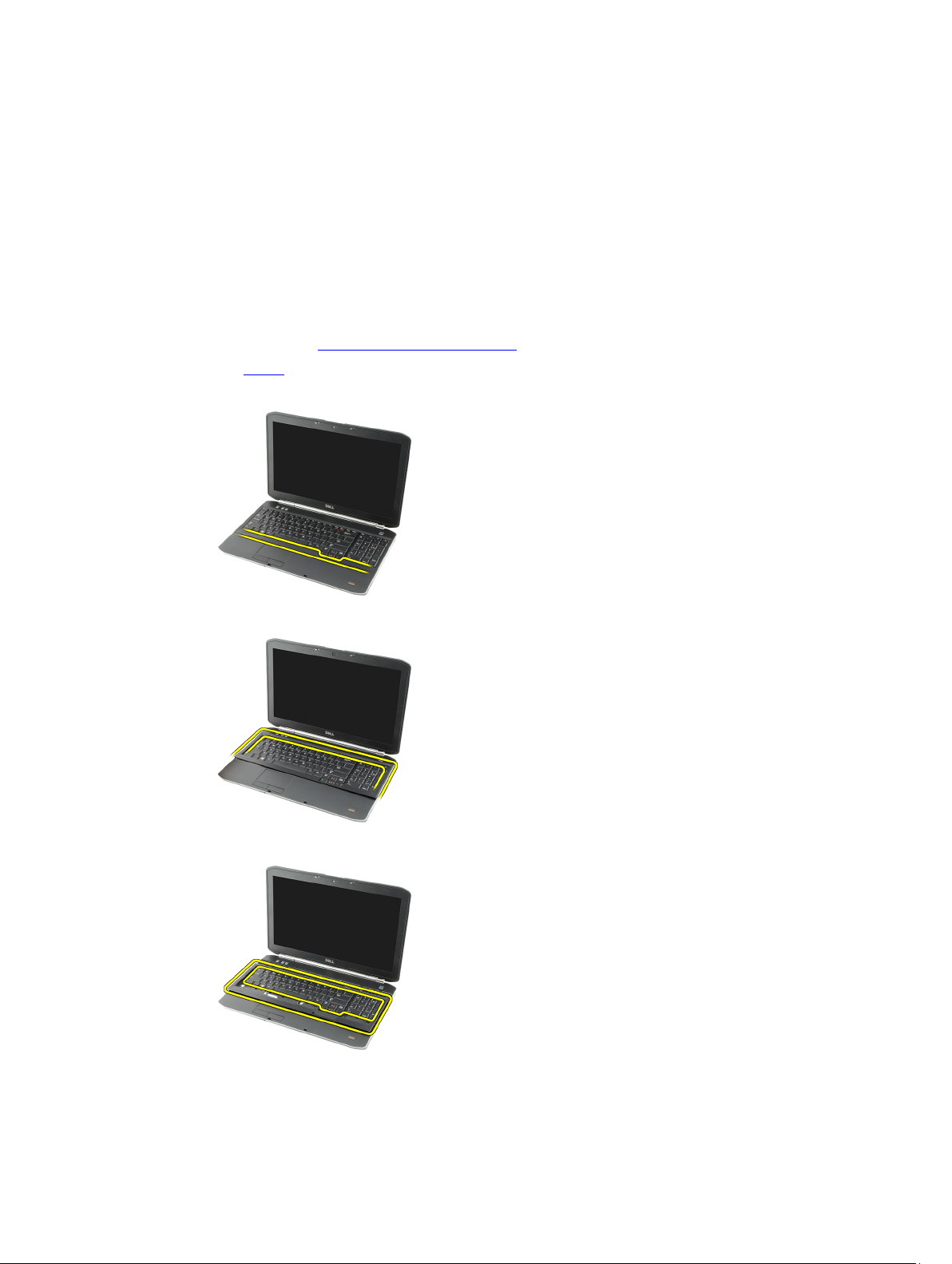
Keyboard Trim
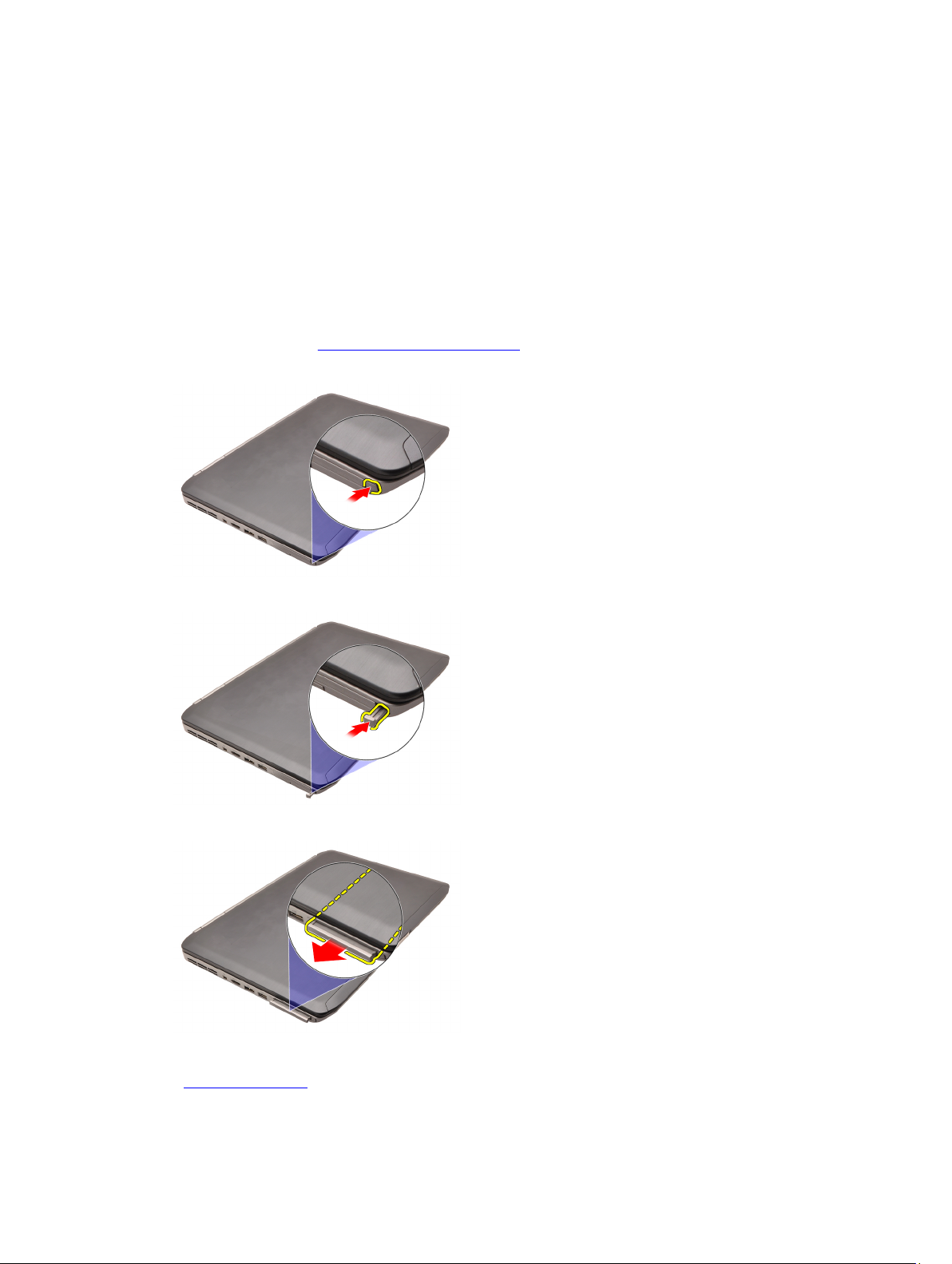
Removing the Keyboard Trim
1. Follow the procedures in Before Working On Your Computer
2. Remove the battery.
3. Pry up the keyboard trim from the bottom edge.
4. Pry up the keyboard trim from the top edge.
8
5. Remove the keyboard trim from the computer.
Related Links
23
Page 24

Installing the Keyboard Trim
Installing the Keyboard Trim
1. Align the keyboard trim with the tabs on top of the palm rest.
2. Press the keyboard trim down along the edges until it clicks into place.
3. Replace the battery.
4. Follow the procedures in After Working Inside Your Computer.
Related Links
Removing the Keyboard Trim
24
Page 25
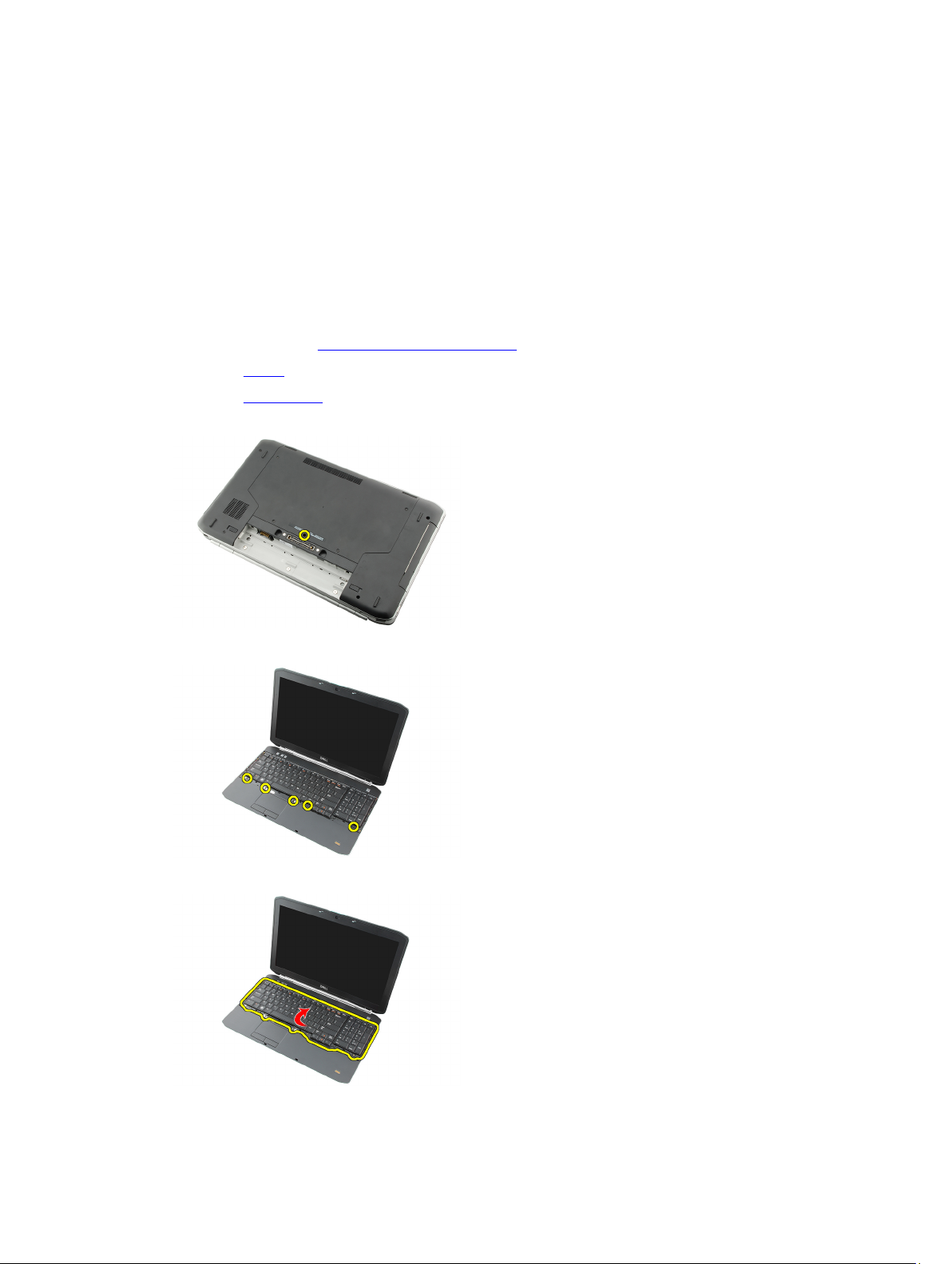
Keyboard
Removing the Keyboard
1. Follow the procedures in Before Working On Your Computer
2. Remove the battery.
3. Remove the keyboard trim.
4. Flip the computer and remove the screw that secures the keyboard to the back of the computer.
5. Flip the computer and remove the screws that secure the keyboard to the front of the computer.
9
6. Pry the keyboard from its edges and turn the keyboard over.
25
Page 26
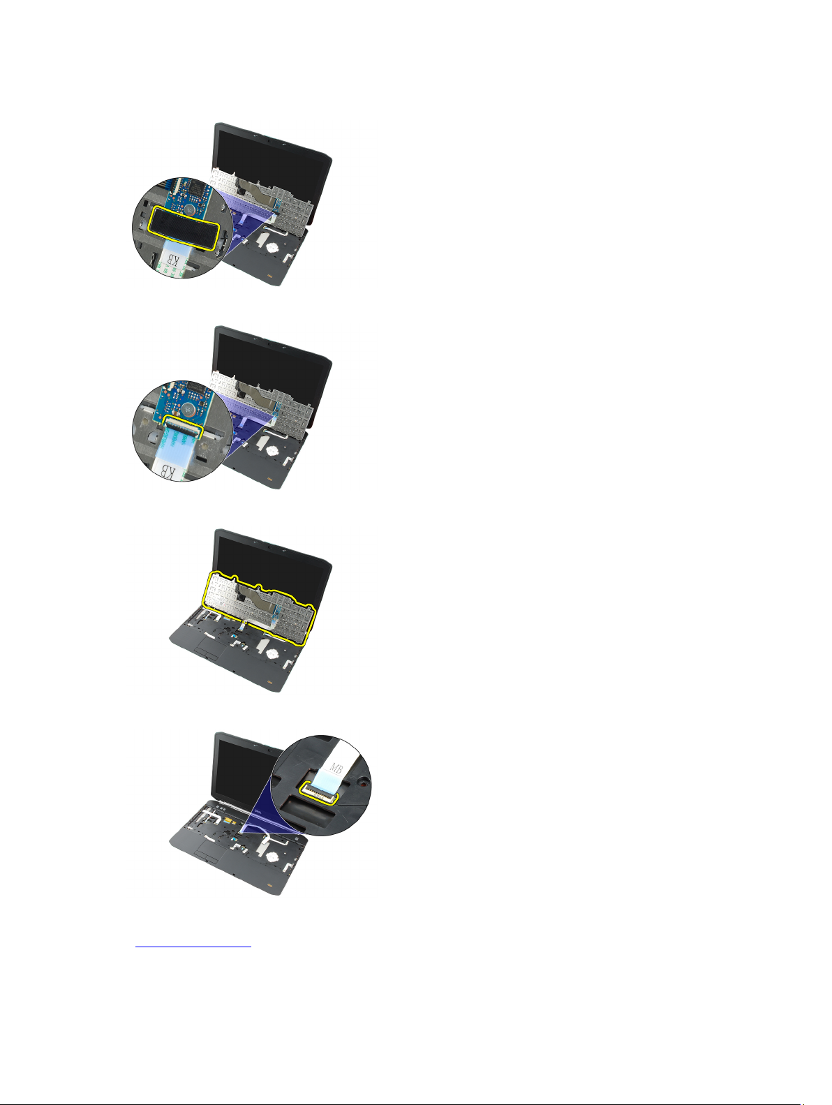
7. Remove the mylar tape that secures the keyboard data cable to the back of the keyboard.
8. Disconnect the keyboard data cable.
9. Flip the keyboard.
10. Disconnect the keyboard data cable and remove it from the computer.
Related Links
Installing the Keyboard
26
Page 27

Installing the Keyboard
1. Connect the keyboard-data cable to the system board.
2. Connect the keyboard-data cable to the back of the keyboard.
3. Replace the tape to secure the keyboard-data cable to the back of the keyboard.
4. Replace the keyboard on the palm rest to align the screw holes.
5. Tighten the keyboard screws.
6. Flip the computer and tighten the screw on the back of the computer.
7. Replace the keyboard trim.
8. Replace the battery.
9. Follow the procedures in After Working Inside Your Computer.
Related Links
Removing the Keyboard
27
Page 28

28
Page 29
Optical Drive
Removing the Optical Drive
1. Follow the procedures in Before Working On Your Computer.
2. Remove the battery.
3. Remove the back panel.
4. Remove the screw that secures the optical drive to the computer.
5. Push the screw tab away from the computer to release the optical drive from the drive bay.
10
6. Remove the optical drive from the computer.
Related Links
29
Page 30

Installing the Optical Drive
Installing the Optical Drive
1. Slide the optical drive into the drive bay on the right side of the computer.
2. Tighten the screw on the back of the computer to secure the optical drive.
3. Replace the back panel.
4. Replace the battery.
5. Follow the procedures in After Working Inside Your Computer.
Related Links
Removing the Optical Drive
30
Page 31

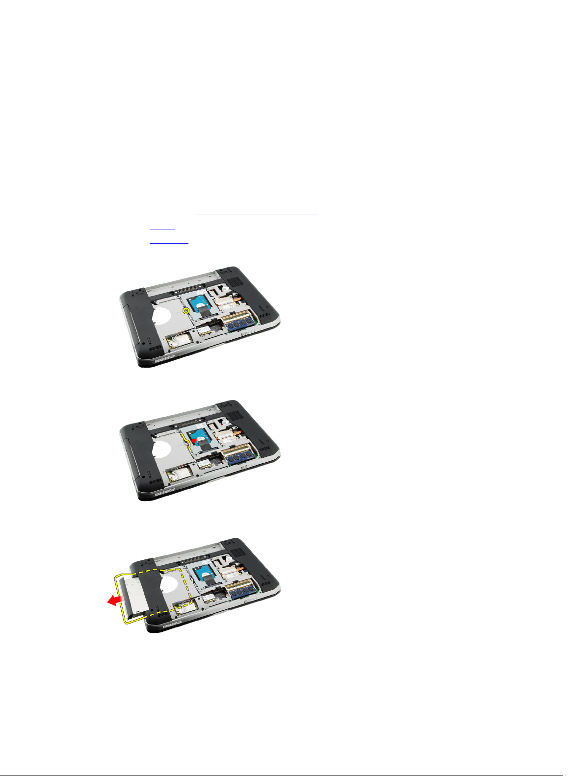
Hard Drive
Removing the Hard Drive
1. Follow the procedures in Before Working On Your Computer.
2. Remove the battery.
3. Remove the back panel.
4. Remove the screws that secure the hard-drive bracket to the computer.
5. Use the tab to pull the hard-drive bracket upward and remove it from the computer.
11
6. Remove the hard-drive bracket screws.
31
Page 32

7. Disconnect the bracket from the hard drive.
8. Disconnect the hard-drive connector from the hard drive.
Related Links
Installing the Hard Drive Assembly
Installing the Hard Drive
1. Reconnect the hard-drive connector to the hard drive.
2. Attach the hard-drive bracket to the hard drive.
3. Tighten the hard-drive bracket screws to ensure that the bracket is correctly aligned and holding the hard drive.
4. Slide the hard drive into the bay towards the connector on the system board.
5. Tighten the screws to secure the hard drive.
6. Replace the back panel.
7. Replace the battery.
8. Follow the procedures in After Working Inside Your Computer.
Related Links
Removing the Hard Drive Assembly
32
Page 33

Wireless Local Area Network (WLAN) Card
Removing the Wireless Local Area Network (WLAN) Card
1. Follow the procedures in Before Working On Your Computer.
2. Remove the battery.
3. Remove the back panel.
4. Disconnect the antenna cables from the WLAN card.
5. Remove the screw that secures the WLAN card to system board.
12
6. Remove the WLAN card.
33
Page 34

Related Links
Installing the Wireless Local Area Network (WLAN) Card
Installing The Wireless Local Area Network (WLAN) Card
1. Slide the WLAN card into its slot.
2. Tighten the screw to secure the WLAN card to the computer.
3. Connect the antenna cables according to the color code on the WLAN card.
4. Replace the back panel.
5. Replace the battery.
6. Follow the procedures in After Working Inside Your Computer.
Related Links
Removing the Wireless Local Area Network (WLAN) Card
34
Page 35

Wireless Wide Area Network (WWAN) Card
Removing the Wireless Wide Area Network (WWAN) Card
1. Follow the procedures in Before Working On Your Computer.
2. Remove the battery.
3. Remove the back panel.
4. Disconnect the antenna cables from the WWAN card.
5. Remove the screw that secures the WWAN card to the system board.
13
6. Remove the WWAN card.
35
Page 36

Related Links
Installing the Wireless Wide Area Network (WWAN) card
Installing The Wireless Wide Area Network (WWAN) Card
1. Slide the WWAN card into its slot.
2. Tighten the screw to secure the WWAN card to the computer.
3. Connect the antenna cables according to the color code on the WWAN card.
4. Replace the back panel.
5. Replace the battery.
6. Follow the procedures in After Working Inside Your Computer.
Related Links
Removing the Wireless Wide Area Network (WWAN) Card
36
Page 37

Memory
Removing the Memory Module
1. Follow the procedures in Before Working On Your Computer.
2. Remove the battery.
3. Remove the back panel.
4. Pry the retention clips away from the memory module.
5. Remove the memory module from the computer.
14
Related Links
Installing The Memory Module
Installing the Memory Module
1. Insert the memory module into the slot in the computer.
2. Press down the memory module until the retention clips secure the memory module.
3. Replace the back panel.
4. Replace the battery.
5. Follow the procedures in After Working Inside Your Computer.
37
Page 38

Related Links
Removing the Memory Module
38
Page 39

CPU Door
Removing the CPU Door
1. Follow the procedures in Before Working On Your Computer.
2. Remove the battery.
3. Remove the back panel.
4. Remove the screws that secure the CPU door to the computer.
5. Remove the CPU door.
15
Related Links
Installing the CPU Door
Installing the CPU Door
1. Slide the CPU door downwards and towards the back of the computer.
2. Tighten the screws to secure the CPU door.
3. Replace the back panel.
4. Replace the battery.
5. Follow the procedures in After Working Inside Your Computer.
39
Page 40

Related Links
Removing the CPU Door
40
Page 41

Heat Sink
Removing the Heat Sink
1. Follow the procedures in Before Working On Your Computer.
2. Remove the battery.
3. Remove the back panel.
4. Remove the CPU door.
5. Loosen the screws on the heat sink.
6. Lift the heat sink and remove it from the computer.
16
Related Links
Installing the Heat Sink
Installing the Heat Sink
1. Tighten the screws as per the numerical sequence on the heat sink module.
2. Replace the CPU door.
3. Replace the back panel.
4. Replace the battery.
5. Follow the procedures in After Working Inside Your Computer.
41
Page 42

Related Links
Removing the Heat Sink
42
Page 43

Processor
Removing the Processor
1. Follow the procedures in Before Working On Your Computer.
2. Remove the battery.
3. Remove the back panel
4. Remove the CPU door.
5. Remove the heat sink.
6. Rotate the processor-cam screw in counter-clockwise direction.
17
7. Remove the processor.
Related Links
Installing the Processor
Installing the Processor
1. Insert the processor into the processor socket.
Ensure that the processor is seated securely.
2. Replace the heat sink.
3. Replace the CPU door.
43
Page 44

4. Replace the back panel.
5. Replace the battery.
6. Follow the procedures in After Working Inside Your Computer.
Related Links
Removing the Processor
44
Page 45

Palm Rest
Removing the Palm Rest
1. Follow the procedures in Before Working On Your Computer.
2. Remove the battery.
3. Remove the back panel.
4. Remove the keyboard trim.
5. Remove the keyboard.
6. Remove the optical drive.
7. Remove the CPU door.
8. Remove the screws from the bottom of the computer.
18
9. Flip the computer and remove the screws on the palm rest.
10. Disconnect the media button cable.
45
Page 46

11. Disconnect the power LED cable.
12. Disconnect the touchpad cable.
13. Disconnect the power-button cable.
14. Disconnect the fingerprint cable.
46
Page 47

15. Lift up the right edge of the palm rest assembly.
16. Release the tabs on the left edge of the palm rest assembly and remove the palm rest.
Related Links
Installing the Palm Rest
Installing the Palm Rest
1. From the left edge of the palm rest, press the palm rest downwards on the computer on all the edges.
2. Press down on all edges to ensure that the tabs are engaged.
3. Connect all the cables to the palm rest.
4. Tighten the screws to secure the palm rest.
5. Flip the computer over and tighten the screws to secure the palm rest.
6. Replace the CPU door.
7. Replace the keyboard.
8. Replace the keyboard trim.
9. Replace the optical drive.
47
Page 48

10. Replace the back panel.
11. Replace the battery.
12. Follow the procedures in After Working Inside Your Computer.
Related Links
Removing the Palm Rest
48
Page 49

ExpressCard/Smart Card/PCMCIA Module
Removing the ExpressCard/Smart Card/PCMCIA Module
1. Follow the procedures in Before Working On Your Computer.
2. Remove the battery.
3. Remove the back panel.
4. Remove the keyboard trim.
5. Remove the keyboard.
6. Remove the optical drive.
7. Remove the CPU door.
8. Remove the palm rest.
9. Remove the screws that secure the ExpressCard/Smart Card/PCMCIA module to the computer.
19
10. Remove the ExpressCard/Smart Card/PCMCIA module.
Related Links
Installing the ExpressCard/Smart Card/PCMCIA module
49
Page 50

Installing the ExpressCard/Smart Card/PCMCIA Module
1. Attach the connector on the back of the ExpressCard/Smart Card/PCMCIA module to the marking on the connector
on the system board.
2. Tighten the screws to secure the ExpressCard/Smart Card/PCMCIA module.
3. Replace the palm rest.
4. Replace the CPU door.
5. Replace the keyboard trim.
6. Replace the keyboard.
7. Replace the optical drive.
8. Replace the back panel.
9. Replace the battery.
10. Follow the procedures in After Working Inside Your Computer.
Related Links
Removing the ExpressCard/Smart Card/PCMCIA Module
50
Page 51

Bluetooth Card
Removing the Bluetooth Card
1. Follow the procedures in Before Working On Your Computer.
2. Remove the battery.
3. Remove the back panel.
4. Remove the keyboard trim.
5. Remove the keyboard.
6. Remove the optical drive.
7. Remove the CPU door.
8. Remove the palm rest.
9. Disconnect the Bluetooth cable from the system board.
20
10. Remove the screw that secures the Bluetooth card.
11. Remove the Bluetooth card.
51
Page 52

12. Disconnect the Bluetooth cable from the Bluetooth card.
Related Links
Installing the Bluetooth Card
Installing the Bluetooth Card
1. Connect the Bluetooth card cable to the card.
2. Place the Bluetooth card in the computer.
3. Tighten the screw to secure the Bluetooth card in the computer.
4. Connect the Bluetooth cable to the system board.
5. Replace the palm rest.
6. Replace the CPU door.
7. Replace the keyboard trim.
8. Replace the keyboard.
9. Replace the optical drive.
10. Replace the back panel.
11. Replace the battery.
12. Follow the procedures in After Working Inside Your Computer.
Related Links
Removing the Bluetooth Card
52
Page 53

Display Assembly
Removing the Display Assembly
1. Follow the procedures in Before Working On Your Computer.
2. Remove the battery.
3. Remove the back panel.
4. Remove the keyboard trim.
5. Remove the keyboard.
6. Remove the optical drive.
7. Remove the hard drive.
8. Remove the CPU door.
9. Remove the palm rest.
10. Disconnect the antenna cables.
21
11. Remove the antenna cables from the routing channels.
12. Disconnect the low-voltage differential signaling (LVDS) cable.
53
Page 54

13. Disconnect the camera cable.
14. Pull the antenna cables through the opening at the top of the computer.
15. Remove the screws that secure the display assembly to the computer.
16. Remove the display assembly.
54
Page 55

Related Links
Installing the Display Assembly
Installing the Display Assembly
1. Attach the display assembly to the base of the computer.
2. Tighten the screws to secure the display assembly.
3. Connect the low-signal differential signaling (LVDS) cable to the system board.
4. Connect the camera cable to system board.
5. Push the antenna through the opening to the bottom of the computer.
6. Secure the antenna cable to the routing channels.
7. Connect the antenna to the WLAN/WLAN cards.
8. Replace the palm rest.
9. Replace the CPU door
10. Replace the keyboard.
11. Replace the keyboard trim.
12. Replace the optical drive.
13. Replace the hard drive.
14. Replace the back panel.
15. Replace the battery.
16. Follow the procedures in After Working Inside Your Computer.
Related Links
Removing the Display Assembly
55
Page 56

56
Page 57

Brackets
Removing the Support Brackets
1. Follow the procedures in Before Working On Your Computer.
2. Remove the battery.
3. Remove the back panel.
4. Remove the keyboard trim.
5. Remove the keyboard.
6. Remove the optical drive.
7. Remove the CPU door.
8. Remove the palm rest.
9. Remove the display assembly.
10. Remove the audio board.
11. Remove the bluetooth card.
12. Remove the modem card.
13. Disengage the modem cable and remove the screw that secures the right support bracket.
22
14. Remove the right-support bracket.
15. Disconnect the modem cable from the modem.
57
Page 58

16. Remove the modem cable from the routing channel.
17. Remove the screws that secure the left-support bracket.
18. Slide the left-support bracket along the modem cable and remove it from the computer.
Related Links
Installing the Support Brackets
58
Page 59

Installing the Support Brackets
1. Slide the modem cable through the opening of the left-support bracket.
2. Place the left-support bracket in the original position.
3. Tighten the screws to secure the left-support bracket.
4. Secure the modem connector cable to its routing channel.
5. Connect the modem connector cable to the modem card.
6. Place the right-support bracket in the original position.
7. Tighten the screw to secure the right-support bracket.
8. Replace the modem card.
9. Replace the Bluetooth card.
10. Replace the audio board.
11. Replace the display assembly.
12. Replace the palm rest.
13. Replace the CPU door.
14. Replace the keyboard trim.
15. Replace the keyboard.
16. Replace the optical drive.
17. Replace the back panel.
18. Replace the battery.
19. Follow the procedures in After Working Inside Your Computer.
Related Links
Removing the Support Brackets
59
Page 60

60
Page 61

Modem Card
Removing the Modem Card
1. Follow the procedures in Before Working On Your Computer.
2. Remove the battery.
3. Remove the back panel.
4. Remove the keyboard trim.
5. Remove the keyboard.
6. Remove the optical drive.
7. Remove the hard drive.
8. Remove the CPU door
9. Remove the palm rest.
10. Remove the display assembly.
11. Disconnect the modem cable from the modem.
23
12. Remove the screws that secure the modem card.
13. Lift the modem card, to disengage from the connector on the back of the card, and remove it from the computer.
61
Page 62

Related Links
Installing the Modem Card
Installing the Modem Card
1. Attach the connector on the back of the modem card to the connector on the system board.
2. Tighten the screws to secure the modem card.
3. Connect the modem card cable.
4. Replace the display assembly.
5. Replace the palm rest.
6. Replace the CPU door.
7. Replace the hard drive.
8. Replace the optical drive.
9. Replace the keyboard.
10. Replace the keyboard trim.
11. Replace the back panel.
12. Replace the battery.
13. Follow the procedures in After Working Inside Your Computer.
Related Links
Removing the Modem Card
62
Page 63

Audio Board
Removing the Audio Board
1. Follow the procedures in Before Working On Your Computer.
2. Remove the battery.
3. Remove the back panel.
4. Remove the keyboard trim.
5. Remove the keyboard.
6. Remove the optical drive
7. Remove the CPU door.
8. Remove the palm rest
9. Remove the Bluetooth card
10. Disconnect the audio-board cables from the system board.
24
11. Remove the screw that secures the audio board to the computer.
12. Remove the audio board.
63
Page 64

Related Links
Installing the Audio Board
Installing the Audio Board
1. Place the audio board in the computer.
2. Tighten the screw to secure the audio board.
3. Connect the audio cables to the system board.
4. Replace the bluetooth card.
5. Replace the palm rest.
6. Replace the CPU door.
7. Replace the keyboard trim.
8. Remove the keyboard.
9. Replace the optical drive
10. Replace the back panel.
11. Replace the battery.
12. Follow the procedures in After Working Inside Your Computer.
Related Links
Removing the Audio Board
64
Page 65

System Board
Removing the System Board
1. Follow the procedures in Before Working On Your Computer.
2. Remove the battery.
3. Remove the subscriber identity module (SIM) card
4. Remove the secure digital (SD) card
5. Remove the back panel.
6. Remove the memory
7. Remove the keyboard trim.
8. Remove the keyboard.
9. Remove the optical drive
10. Remove the hard drive.
11. Remove the wireless local area network (WLAN)
12. Remove the wireless wide area network (WWAN)
13. Remove the CPU door.
14. Remove the heat sink.
15. Remove the processor.
16. Remove the palm rest.
17. Remove the ExpressCard/Smart Card/PCMCIA module.
18. Remove the display assembly.
19. Remove the audio board.
20. Remove the Bluetooth.
21. Remove the modem.
22. Remove the support brackets.
23. Disconnect the coin-cell battery cable from the system board.
25
24. Disconnect the thermal fan cable.
65
Page 66

25. Remove the DC-In cable.
26. Disconnect the following cables:
– speaker cable
– bluetooth cable
– audio board cable
27. Remove the screws that secure the system board to the computer.
28. Lift the right edge of the system board, to release it from the port connectors, and remove the system board.
66
Page 67

Related Links
Installing the System Board
Installing the System Board
1. Align the system board to the port connectors and place the system board in the computer.
2. Engage the connector on the back of the system board to the I/O panel.
3. Tighten the screws to secure the system board.
4. Connect the following cables:
– speaker cable
– audio board cable
– bluetooth cable
5. Connect the DC-In cable to the system board.
6. Connect the thermal fan cable to the system board.
7. Connect the coin-cell cable to the system board.
8. Replace the support brackets.
67
Page 68

9. Replace the modem card.
10. Replace the Bluetooth card.
11. Replace the audio board.
12. Replace the display assembly.
13. Replace the ExpressCard/Smart Card/PCMCIA module.
14. Replace the palm rest.
15. Replace the processor.
16. Replace the heat sink.
17. Replace the CPU door.
18. Replace the wireless local area network (WLAN).
19. Replace the wireless wide area network (WWAN).
20. Replace the hard drive.
21. Replace the optical drive.
22. Replace the keyboard.
23. Replace the keyboard trim.
24. Replace the memory.
25. Replace the back panel.
26. Replace the secure digital (SD) card.
27. Replace the subscriber identity module (SIM) card.
28. Replace the battery.
29. Follow the procedures in After Working Inside Your Computer.
Related Links
Removing the System Board
68
Page 69

Coin-Cell Battery
Removing the Coin-Cell Battery
1. Follow the procedures in Before Working On Your Computer.
2. Remove the battery.
3. Remove the back panel.
4. Remove the CPU door.
5. Lift the coin-cell battery from the system board.
6. Pry and remove the coin-cell battery from the adhesive.
26
Related Links
Installing the Coin-Cell Battery
Installing the Coin-Cell Battery
1. Attach the coin-cell battery to the coin-cell compartment.
2. Connect the coin-cell battery to the system board.
3. Replace the CPU door.
4. Replace the back panel.
5. Replace the battery.
69
Page 70

6. Follow the procedures in After Working Inside Your Computer.
Related Links
Removing the Coin-Cell Battery
70
Page 71

Input/Output Panel
Removing the Input/Output (I/O) Panel
1. Follow the procedures in Before Working On Your Computer.
2. Remove the battery.
3. Remove the subscriber identity module (SIM) card
4. Remove the secure digital (SD) card.
5. Remove the back panel.
6. Remove the memory.
7. Remove the keyboard trim.
8. Remove the keyboard.
9. Remove the optical drive.
10. Remove the hard drive.
11. Remove the wireless wide area network (WWAN)
12. Remove the wireless local area network (WLAN).
13. Remove the CPU door.
14. Remove the heat sink.
15. Remove the processor.
16. Remove the palm rest.
17. Remove the ExpressCard/Smart Card/PCMCIA module.
18. Remove the display assembly.
19. Remove the audio board.
20. Remove the Bluetooth card.
21. Remove the modem card.
22. Remove the support brackets.
23. Remove the system board.
24. Remove the screws that secure the I/O panel.
27
25. Remove the I/O panel.
71
Page 72

Related Links
Installing the Input/Output (I/O) Panel
Installing the Input/Output (I/O) Panel
1. Place the I/O panel in the original position.
2. Tighten the screws to secure the I/O panel.
3. Replace the system board.
4. Replace the support brackets.
5. Replace the modem card.
6. Replace the bluetooth card.
7. Replace the audio board.
8. Replace the display assembly.
9. Replace the ExpressCard/Smart Card/PCMCIA module.
10. Replace the palm rest.
11. Replace the processor.
12. Replace the heat sink.
13. Replace the CPU door.
14. Replace the wireless local area network (WLAN).
15. Replace the wireless wide area network (WWAN).
16. Replace the hard drive.
17. Replace the optical drive.
18. Replace the keyboard.
19. Replace the keyboard trim
20. Replace the memory.
21. Replace the modem card.
22. Replace the subscriber identity module (SIM) card.
23. Replace the secure digital (SD) card.
24. Replace the battery.
25. Follow the procedures in After Working Inside Your Computer.
Related Links
Removing the Input/Output (I/O) Panel
72
Page 73

Power Connector
Removing the Power Connector
1. Follow the procedures in Before Working On Your Computer.
2. Remove the battery.
3. Remove the subscriber identity module (SIM) card
4. Remove the secure digital (SD) card.
5. Remove the back panel.
6. Remove the memory.
7. Remove the keyboard trim.
8. Remove the keyboard.
9. Remove the optical drive.
10. Remove the hard drive.
11. Remove the wireless local area network (WLAN)
12. Remove the wireless wide area network (WWAN)
13. Remove the CPU door.
14. Remove the heat sink.
15. Remove the processor.
16. Remove the palm rest..
17. Remove the ExpressCard/Smart Card/PCMCIA module.
18. Remove the display assembly.
19. Remove the audio board.
20. Remove the Bluetooth card.
21. Remove the modem card.
22. Remove the support brackets.
23. Remove the system board.
24. Remove the power connectors cable from the routing channel.
28
25. Remove the power connector.
73
Page 74

Related Links
Installing the Power Connector
Installing the Power Connector
1. Secure the power connector to the routing channel on the processor fan.
2. Replace the system board.
3. Replace the support brackets.
4. Replace the modem card.
5. Replace the bluetooth card.
6. Replace the audio board.
7. Replace the display assembly.
8. Replace the ExpressCard/Smart Card/PCMCIA module.
9. Remove the palm rest.
10. Replace the processor.
11. Replace the heat sink.
12. Remove the CPU door.
13. Replace the wireless wide area network (WWAN).
14. Replace the wireless local area network (WLAN).
15. Replace the hard drive.
16. Replace the optical drive.
17. Remove the keyboard.
18. Remove the keyboard trim.
19. Replace the memory.
20. Replace the back panel.
21. Replace the secure digital (SD) card.
22. Replace the subscriber identity module (SIM) card.
23. Replace the battery.
24. Follow the procedures in After Working Inside Your Computer.
Related Links
Removing the Power Connector
74
Page 75

Modem Connector
Removing the Modem Connector
1. Follow the procedures in Before Working On Your Computer.
2. Remove the battery.
3. Remove the back panel.
4. Remove the keyboard trim.
5. Remove the keyboard.
6. Remove the optical drive.
7. Remove the hard drive.
8. Remove the CPU door.
9. Remove the palm rest.
10. Remove the display assembly.
11. Remove the support brackets.
12. Remove the modem connector.
29
Related Links
Installing the Modem Connector
Installing the Modem Connector
1. Secure the modem connector into the routing channel on the thermal fan.
2. Replace the support brackets.
3. Replace the display assembly.
4. Replace the palm rest.
5. Replace the CPU door.
6. Replace the hard drive.
7. Replace the optical drive.
8. Replace the keyboard.
75
Page 76

9. Replace the keyboard.
10. Replace the keyboard trim.
11. Replace the battery.
12. Follow the procedures in After Working Inside Your Computer.
Related Links
Removing the Modem Connector
76
Page 77

Thermal Fan
Removing the Thermal Fan
1. Follow the procedures in Before Working On Your Computer.
2. Remove the battery.
3. Remove the SIM card.
4. Remove the SD card.
5. Remove the back panel.
6. Remove the memory
7. Remove the keyboard trim.
8. Remove the keyboard.
9. Remove the optical drive.
10. Remove the hard drive.
11. Remove the wireless local area network (WLAN).
12. Remove the wireless wide area network (WWAN)
13. Remove the CPU door.
14. Remove the heat sink.
15. Remove the processor.
16. Remove the palm rest.
17. Remove the ExpressCard/Smart Card/PCMCIA module.
18. Remove the display assembly.
19. Remove the support brackets.
20. Remove the system board.
21. Disengage the DC-In cable from the routing channel.
30
22. Remove the screw that secures the thermal fan.
77
Page 78

23. Remove the thermal fan.
Related Links
Installing the Thermal Fan
Installing the Thermal Fan
1. Place the thermal fan in the original position.
2. Tighten the screw to secure the thermal fan.
3. Replace the system board.
4. Replace the support brackets.
5. Replace the display assembly.
6. Replace the ExpressCard/Smart Card/PCMCIA module.
7. Replace the palm rest.
8. Replace the processor.
9. Replace the heat sink.
10. Replace the CPU door.
11. Replace the wireless local area network (WLAN).
12. Replace the wireless wide area network (WWAN).
13. Replace the hard drive
14. Replace the optical drive
15. Replace the keyboard.
16. Replace the keyboard trim.
17. Replace the memory.
18. Replace the back panel.
19. Replace the secure digital (SD) card.
20. Replace the subscriber identity module (SIM) card.
78
Page 79

21. Replace the battery.
22. Follow the procedures in After Working Inside Your Computer.
Related Links
Removing the Thermal Fan
79
Page 80

80
Page 81

Speaker
Removing the Speakers
1. Follow the procedures in Before Working On Your Computer.
2. Remove the battery.
3. Remove the secure digital (SD) card.
4. Remove the subscriber identity module (SIM) card.
5. Remove the back panel.
6. Remove the memory.
7. Remove the keyboard trim.
8. Remove the keyboard.
9. Remove the optical drive.
10. Remove the hard drive.
11. Remove the wireless local area network (WLAN).
12. Remove the wireless wide area network (WWAN).
13. Remove the CPU door.
14. Remove the heat sink
15. Remove the processor
16. Remove the palm rest.
17. Remove the ExpressCard/Smart Card/PCMCIA module.
18. Remove the display assembly.
19. Remove the audio board.
20. Remove the Bluetooth card
21. Remove the modem card.
22. Remove the support brackets.
23. Remove the system board.
24. Remove the screws that secure the speakers.
31
25. Remove the speaker cables from the routing guides.
81
Page 82

26. Remove the speakers.
Related Links
Installing the Speakers
Installing the Speakers
1. Secure the speaker cables to the routing channels.
2. Replace the speakers in the original position.
3. Tighten the screws to secure the speakers.
4. Replace the system board.
5. Replace the support brackets.
6. Replace the modem card.
7. Replace the Bluetooth card.
8. Replace the audio board.
9. Replace the display assembly.
10. Replace the ExpressCard/Smart Card/PCMCIA module.
11. Remove the palm rest.
12. Replace the processor.
13. Replace the heat sink.
14. Replace the CPU door.
15. Replace the wireless local area network (WLAN).
16. Replace the wireless wide area network (WWAN).
17. Replace the hard drive.
18. Replace the optical drive.
19. Replace the keyboard.
20. Replace the keyboard trim.
82
Page 83

21. Replace the memory.
22. Replace the back panel.
23. Replace the secure digital (SD) card.
24. Replace the subscriber identity module (SIM) card.
25. Replace the battery.
26. Follow the procedures in After Working Inside Your Computer.
Related Links
Removing the Speakers
83
Page 84

84
Page 85

Display Bezel
Removing the Display Bezel
1. Follow the procedures in Before Working On Your Computer.
2. Remove the battery.
3. Pry up the bottom edge of the display bezel.
4. Work your way around the sides and the top edge of the display bezel.
32
5. Remove the display bezel.
Related Links
85
Page 86

Installing the Display Bezel
Installing the Display Bezel
1. Place the display bezel in the original position.
2. From the top edge, press downward on the display bezel to engage the tabs.
3. Work your way around the side and the bottom edge.
4. Replace the battery.
5. Follow the procedures in After Working Inside Your Computer.
Related Links
Removing the Display Bezel
86
Page 87

Display Panel
Removing the Display Panel
1. Follow the procedures in Before Working On Your Computer.
2. Remove the battery.
3. Remove the display bezel.
4. Remove the screws that secure that back panel.
5. Flip the display panel and disconnect the low-voltage differential signalling (LVDS) cable.
33
6. Remove the display panel from the display assembly.
87
Page 88

Related Links
Installing the Display Panel
Installing the Display Panel
1. Align the display brackets with the display panel.
2. Tighten the screws to secure the display panel.
3. Connect the low-voltage differential signalling (LVDS) cable to the back of the display panel.
4. Place the display panel in the display cover.
5. Tighten the screws to secure the display panel.
6. Replace the display bezel.
7. Replace the battery.
8. Follow the procedures in After Working Inside Your Computer.
Related Links
Removing the Display Panel
88
Page 89

Display Hinges
Removing the Display Hinges
1. Follow the procedures in Before Working On Your Computer.
2. Remove the battery.
3. Remove the back panel.
4. Remove the keyboard trim.
5. Remove the keyboard.
6. Remove the optical drive.
7. Remove the CPU door.
8. Remove the palm rest.
9. Remove the display assembly.
10. Remove the display bezel.
11. Remove the display panel.
12. Remove the screws that secure the display hinges.
34
13. Remove the display-hinge caps.
14. Rotate the right-display hinge tower to a vertical position.
89
Page 90

15. Pull the antenna cable routed through the right-hinge tower through the opening on the right side.
16. Pull the right-hinge tower along the antenna cables and remove it.
17. Remove the left-display hinge cap.
18. Remove the left-display hinge tower.
90
Page 91

19. Release and remove the left-hinge tower from the cables.
Related Links
Installing the Display Hinges
Installing the Display Hinges
1. Replace the left hinge tower with the offset end facing inward.
2. Position the low-voltage differential signaling (LVDS) and camera cables through the hinge tower slits towards the
centre of the display cover.
3. Insert the left-display hinge into the hinge tower.
4. Insert the left-display hinge cap on the end of the left hinge.
5. Insert the antenna cables through the right hinge tower with the hinge tower offset facing inward.
6. Position the antenna cables through the hinge tower slits towards the center of the display cover.
7. Insert the right-display hinge into the right hinge tower.
8. Insert the right-display hinge cap on the end of the right hinge.
9. Replace and tighten the screws to secure the display hinges.
10. Replace the display panel.
11. Replace the display bezel.
12. Replace the display assembly.
13. Replace the palm rest.
14. Replace the CPU door.
15. Replace the hard drive.
16. Replace the optical drive.
17. Replace the keyboard.
18. Replace the keyboard trim.
19. Replace the back panel.
91
Page 92

20. Replace the battery.
21. Follow the procedures in After Working Inside Your Computer.
Related Links
Removing the Display Hinges
92
Page 93

Camera
Removing the Camera
1. Follow the procedures in Before Working On Your Computer.
2. Remove the battery.
3. Remove the display bezel.
4. Remove the display panel.
5. Disconnect the camera cable.
6. Loosen the screw that secures the camera and the microphone module.
35
7. Lift and remove the camera module.
93
Page 94

Related Links
Installing the Camera
Installing the Camera
1. Place the camera module on the display cover.
2. Replace and tighten the screw to secure the camera.
3. Connect the camera cable to the camera module.
4. Replace the display panel.
5. Replace the display bezel.
6. Replace the battery.
7. Follow the procedures in After Working Inside Your Computer.
Related Links
Removing the Camera
94
Page 95

Specifications
Technical Specifications
NOTE: Offerings may vary by region. The following specifications are only those required by law to ship with your
computer. For more information regarding the configuration of your computer, click Start → Help and Support and
select the option to view information about your computer.
System Information
Chipset
Latitude 5420/E5420/ 5520/E5520 Intel HM65 Express chipset
Latitude E5420m/E5520m Intel GM45 Express chipset
DRAM bus width 64-bit
Flash EPROM SPI 32 Mbits
PCIe Gen1 bus 100 MHz
Processor
Types
36
Latitude 5420/E5420/ 5520/E5520 Intel Core i3/i5/i7 series
Latitude E5420m/E5520m Intel Core 2 series
Intel Celeron (Socket P) series
Memory
Memory connector two SODIMM slots
Memory capacity 1 GB, 2 GB, 4 GB, or 8 GB
Memory type
Latitude 5420/E5420/5520/E5520 DDR3 SDRAM, 1333 MHz
Latitude E5420m/E5520m DDR3 SDRAM, 1066 MHz
Minimum memory 1 GB
Maximum memory 8 GB
NOTE: Only 64-bit operating systems support more than
4 GB memory.
95
Page 96

Audio
Type two-channel high definition audio
Controller 92HD90B
Stereo Conversion 24-bit (analog-to-digital and digital-to-analog)
Interface:
Internal high definition audio
External microphone-in connector, stereo headphones/external
speakers connector
Speakers 1.5 W stereo
Internal speaker amplifier 1.5 W mono
Volume controls media buttons for Media control
Video
Type Intel UMA video
Data bus integrated video
Video controller
Latitude 5420/E5420/5520/E5520 Intel HD Graphics
Intel HD Graphics 3000
Latitude E5420m/E5520m Intel GM45
Output 15-pin video connector
19-pin HDMI connector
Communications
Network adapter 10/100/1000 Mbps Ethernet LAN
Wireless internal wireless local area network (WLAN), wireless wide
area network (WWAN), and Bluetooth wireless support
Ports and Connectors
Audio microphone connector, stereo headphone/speakers
connector
Video 15-pin VGA connector
Network adapter RJ-45 connector
USB three 4-pin USB 2.0-compliant connectors, one eSATA/USB
2.0-compliant connector
Memory card reader 5-in-1 memory card reader
96
Page 97

Display
Type White Light Emitting Diode (WLED) display
Size
Latitude 5420/E5420/E5420m 14.0 inch high definition WLED
Latitude 5520/E55420/E5520m 15.6 inch high definition WLED
Active area (X/Y)
Latitude 5420/E5420/E5420m 309.60 mm/173.90 mm
Latitude 5520/E55420/E5520m 344.20 mm/193.50 mm
Dimensions:
Height
Latitude 5420/E5420/E5420m 192.50 mm (7.57 inches)
Latitude 5520/E55420/E5520m 210.00 mm (8.27 inches)
Width
Latitude 5420/E5420/E5420m 324.00 mm (12.75 inches)
Latitude 5520/E55420/E5520m 360.00 mm (14.17 inches)
Z-Height
Latitude 5420/E5420/E5420m 5.20 mm (0.20 inch)
Latitude 5520/E55420/E5520m 5.80 mm (0.23 inch)
Diagonal
Latitude 5420/E5420/E5420m 344.6 mm (14.00 inches)
Latitude 5520/E55420/E5520m 396.24 mm (15.60 inches)
Maximum resolution
Latitude 5420/E5420/E5420m
HD 1366 x 768 at 262 K colors
HD+ 1600 x 900 at 262 K colors
Latitude 5520/E55420/E5520m
HD 1366 x 768 at 263 K colors
FHD 1920 x 1080 at 262 K colors
Typical Brightness 200 nits
Operating angle 0° (closed) to 135°
Refresh rate 60 Hz
Minimum Viewing angles:
Horizontal +40°/–40°
Vertical +10°/–30°
97
Page 98

Display
Pixel pitch
Latitude 5420/E5420/E5420m
HD 0.2265 mm x 0.2265 mm
HD+ 0.1935 mm x 0.1935 mm
Latitude 5520/E55420/E5520m
HD 0.2520 mm x 0.2520 mm
FHD 0.1935 mm x 0.1935 mm
Keyboard
Number of keys United States: 86 keys, United Kingdom: 87 keys, Brazil: 87
keys, and Japan: 90 keys
Layout QWERTY/AZERTY/Kanji
Touchpad
Active Area
X-axis 80.00 mm
Y-axis 40.70 mm
Battery
Type 4-, 6- or 9-cell "smart" lithium ion
Dimensions:
Height
4-, 6-, and 9-cell 20.00 mm (0.79 inch)
Width
4- and 6-cell 208.00 mm (8.18 inches)
9-cell 214.00 mm (8.43 inches)
Depth
4- and 6-cell 48.08 mm (1.89 inches)
9-cell 71.79 mm (2.83 inches)
Weight
4-cell 240.00 g (0.53 lb)
6-cell 344.73 g (0.76 lb)
9-cell 508.20 g (1.12 lb)
Voltage
98
Page 99

Battery
4-cell 14.8 VDC
6- and 9-cell 11.1 VDC
Temperature range:
Operating 0 °C to 50 °C (32 °F to 122 °F)
Non-Operating –40 °C to 85 °C (–40 °F to 185 °F)
NOTE: The battery pack is capable of safely
withstanding the above storage temperatures with
100% charge.
NOTE: The battery pack is also capable of withstanding
storage temperatures from –20 °C to +60 °C with no
degradation in its performance.
Coin-cell battery 3 V CR2032 lithium coin cell
AC Adapter
Input voltage 100 VAC to 240 VAC
Input current (maximum) 1.5 A, 1.6 A, or 1.7 A
Input frequency 50 Hz to 60 Hz
Output power 65 W or 90 W
Output current 65 W 90 W
3.34 A (continuous) 4.62 A (continuous)
Rated output voltage 19.5 +/– 1.0 VDC
Dimensions
65 W 90 W
Height 16.00 mm (0.63 inch) 16.00 mm (0.63 inch)
Width 66.00 mm (2.60 inches) 70.00 mm (2.76 inches)
Length 127.00 mm (5.00 inches) 147.00 mm (5.79 inches)
Temperature range:
Operating 0 °C to 40 °C (32 °F to 104 °F)
Non-Operating –40 °C to 70 °C (–40 °F to 158 °F)
Physical
Height
Latitude 5420/E5420/E5420m 29.90 mm to 32.50 mm (1.18 inches to 1.28 inches)
Latitude 5520/E5520/E5520m 30.20 mm to 33.20 mm (1.19 inches to 1.31 inches)
Width
99
Page 100

Physical
Latitude 5420/E5420/E5420m 350.00 mm (13.78 inches)
Latitude 5520/E5520/E5520m 388.00 mm (15.28 inches)
Depth
Latitude 5420/E5420/E5420m 240.00 mm (9.45 inches)
Latitude 5520/E5520/E5520m 251.00 mm (9.88 inches)
Weight
Latitude 5420/E5420/E5420m 2.27 kg (5.00 lb)
Latitude 5520/E5520 2.54 kg (5.60 lb)
Latitude E5520m 2.63 kg (5.80 lb)
Environmental
Temperature:
Operating 0 °C to 35 °C (32 °F to 95 °F)
Storage –40 °C to 65 °C (–40 °F to 149 °F)
Relative humidity (maximum):
Operating 10 % to 90 % (noncondensing)
Storage 5 % to 95 % (noncondensing)
Altitude (maximum):
Operating –15.20 m to 3048 m (–50 ft to 10,000 ft)
Non-Operating –15.20 m to 10,668 m (–50 ft to 35,000 ft)
Airborne contaminant level G1 or lower as defined by ISA-S71.04–1985
100
 Loading...