

Page 1

Dell Latitude D400 Service Manual
Dell™ Latitude™ D400 Service Manual
Before You Begin
Preparing to Work Inside the Computer
Recommended Tools
Computer Orientation
Screw Identification
Using the Dell Diagnostics
When to Use the Dell Diagnostics
Features of the Dell Diagnostics
Starting the Dell Diagnostics
System Components
Keyboard
Removing the Keyboard
Installing the Keyboard
Memory
Installing a Memory Module Under the Memory
Module/Modem Cover
Installing a Memory Module Under the Keyboard
Mini PCI Card
Modem
Hard Drive
Removing the Hard Drive
Installing the Hard Drive
Removing the Interposer
Replacing the Interposer
Docking Doors
Removing the Docking Doors
Installing the Docking Doors
Bluetooth™
Display
Removing the Display Assembly
Replacing the Display Latch
Palm Rest
Cooling Fan
file:///F|/Service%20Manuals/Dell/Latitude/d400/index.htm (1 of 3) [2/28/2004 8:05:56 AM]
Page 2
Dell Latitude D400 Service Manual
Touch Pad
System Board
Removing the System Board
Replacing the System Board
Reserve Battery
Flashing the BIOS
Speakers
Battery Latch
Pin Assignments for I/O Connectors
USB Connector
Video Connector
Serial Connector
Dell D/Bay Connector
Mini Recommended Spares List
Notes, Notices, and Cautions
NOTE: A NOTE indicates important information that helps you make better use
of your computer.
NOTICE: A NOTICE indicates either potential damage to hardware or loss of
data and tells you how to avoid the problem.
CAUTION: A CAUTION indicates a potential for property damage,
personal injury, or death.
Trademarks used in this text: Dell, the DELL logo, and Latitude are trademarks of Dell Inc.; Microsoft
and Windows are registered trademarks of Microsoft Corporation; Bluetooth is a trademark owned by
Bluetooth SIG, Inc. and is used by Dell Inc. under license.
Other trademarks and trade names may be used in this document to refer to either the entities
claiming the marks and names or their products. Dell Inc. disclaims any proprietary interest in
trademarks and trade names other than its own.
file:///F|/Service%20Manuals/Dell/Latitude/d400/index.htm (2 of 3) [2/28/2004 8:05:56 AM]
Page 3

Dell Latitude D400 Service Manual
Model PPT
October 2003 Rev. A02
file:///F|/Service%20Manuals/Dell/Latitude/d400/index.htm (3 of 3) [2/28/2004 8:05:56 AM]
Page 4
Before You Begin: Dell Latitude D400 Service Manual
Back to Contents Page
Before You Begin
Dell™ Latitude™ D400 Service Manual
Preparing to Work Inside the Computer
Recommended Tools
Computer Orientation
Screw Identification
Preparing to Work Inside the Computer
CAUTION: Only a certified service technician should perform repairs on
your computer. Damage due to servicing that is not authorized by Dell
is not covered by your warranty. Read and follow the safety instructions
in the System Information Guide that came with the computer.
CAUTION: To prevent static damage to components inside your
computer, discharge static electricity from your body before you touch
any of your computer's electronic components. You can do so by
touching an unpainted metal surface.
CAUTION: Handle components and cards with care. Do not touch the
components or contacts on a card. Hold a card by its edges or by its
metal mounting bracket. Hold a component such as a microprocessor by
its edges, not by its pins.
NOTICE: To avoid damaging the computer, perform the following steps before
you begin working inside the computer.
1. Ensure that the work surface is flat and clean to prevent scratching the
computer cover.
2. Save any work in progress and exit all open programs.
3. Turn off the computer and all attached devices.
file:///F|/Service%20Manuals/Dell/Latitude/d400/begin.htm (1 of 7) [2/28/2004 8:06:07 AM]
Page 5

Before You Begin: Dell Latitude D400 Service Manual
NOTE: Ensure that the computer is off and not in a power management mode.
If you cannot shut down the computer using the computer operating system,
press and hold the power button for 4 seconds.
4. If the computer is connected to a docking device (docked), undock it.
5. Disconnect the computer from the electrical outlet.
6. To avoid possible damage to the system board, wait 10 to 20 seconds and then
disconnect any attached devices.
7. Disconnect all other external cables from the computer.
8. Remove any installed PC Cards from the PC Card slot.
9. Close the display and turn the computer upside down on a flat work surface.
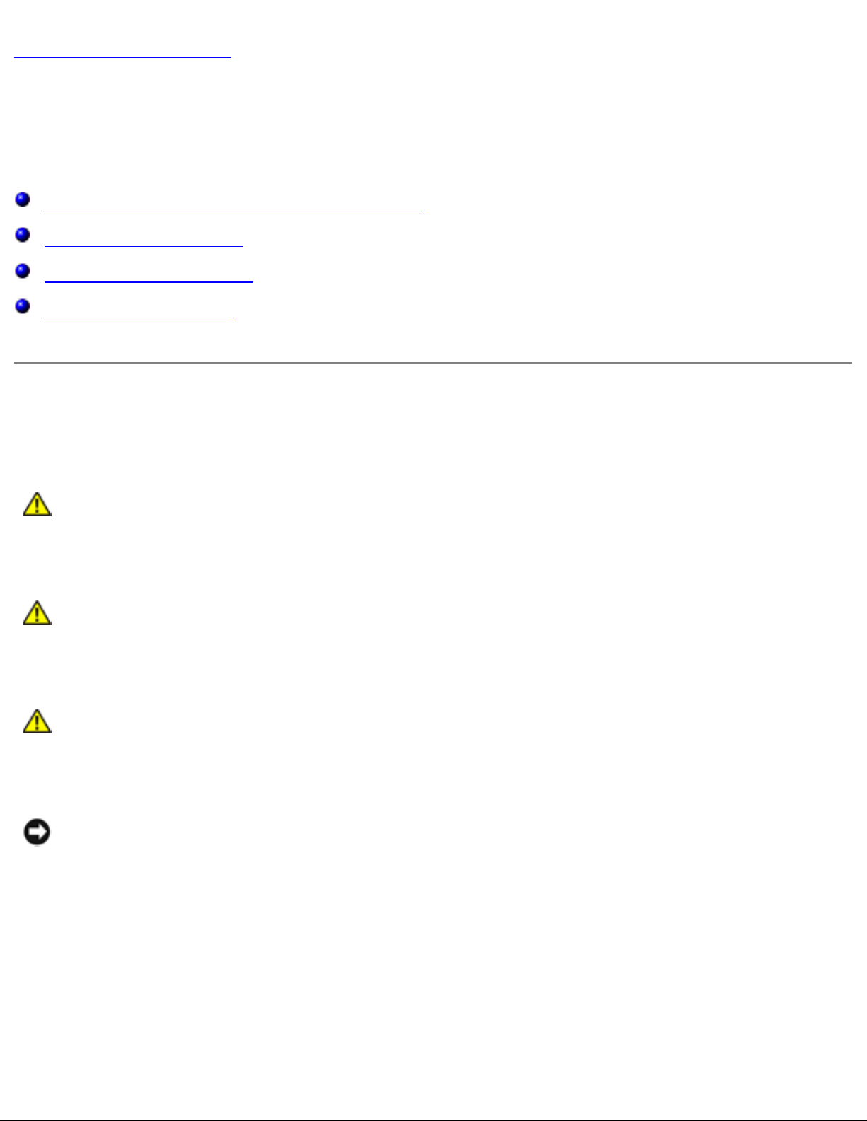
NOTICE: To avoid damaging the system board, you must remove the main
battery before you service the computer.
10. Slide and hold the battery-bay latch release on the bottom of the computer, and
then remove the battery from the bay.
file:///F|/Service%20Manuals/Dell/Latitude/d400/begin.htm (2 of 7) [2/28/2004 8:06:07 AM]
Page 6
Before You Begin: Dell Latitude D400 Service Manual
Recommended Tools
The procedures in this manual require the following tools:
● Phillips screwdriver
● Flat-blade screwdriver
● Small plastic scribe
● Flash BIOS update program floppy disk or CD
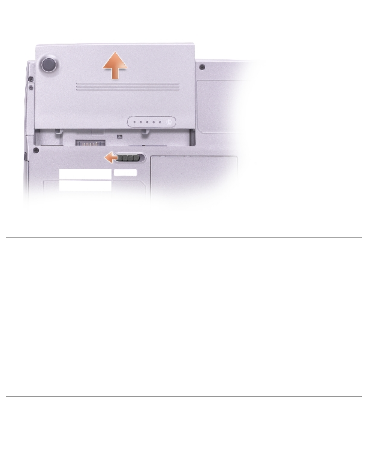
Computer Orientation
file:///F|/Service%20Manuals/Dell/Latitude/d400/begin.htm (3 of 7) [2/28/2004 8:06:07 AM]
Page 7
Before You Begin: Dell Latitude D400 Service Manual
1
back
2
right
3
front
4
left
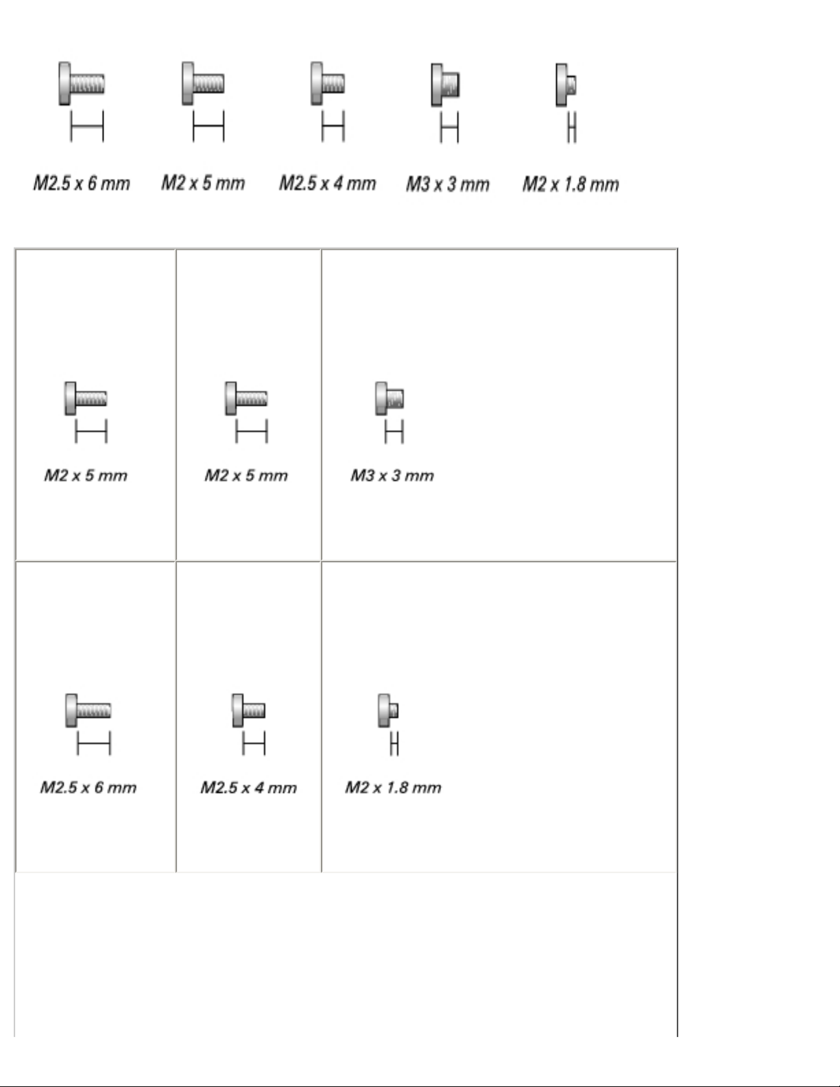
Screw Identification
When you are removing and replacing components, photocopy "Screw Identification"
as a tool to lay out and keep track of the screws. The screw identification chart
provides the number of screws and their sizes.
file:///F|/Service%20Manuals/Dell/Latitude/d400/begin.htm (4 of 7) [2/28/2004 8:06:07 AM]
Page 8
Before You Begin: Dell Latitude D400 Service Manual
keyboard
(two each)
1428U
modem
(one each)
1428U
hard drive
(four each)
2864D
display removal
(six each)
4911U
display bezel
(six each)
7166P
display latch
(two each)
5H953
file:///F|/Service%20Manuals/Dell/Latitude/d400/begin.htm (5 of 7) [2/28/2004 8:06:07 AM]
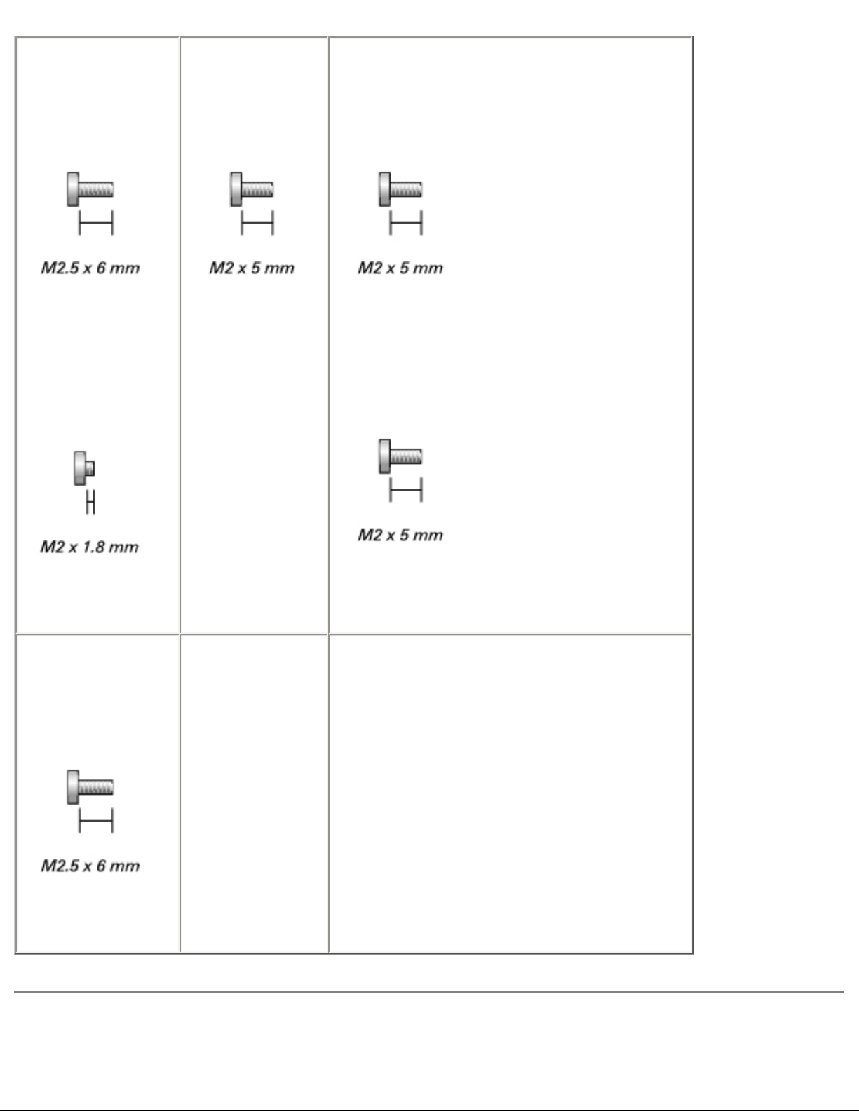
Page 9
Before You Begin: Dell Latitude D400 Service Manual
palm rest
(thirteen each)
4911U
(two each)
5H953
fan
(three each)
1428U
system board
(six each)
1428U
(one each, if a BIOS card is present)
1428U
speakers
(two each)
4911U
Back to Contents Page
file:///F|/Service%20Manuals/Dell/Latitude/d400/begin.htm (6 of 7) [2/28/2004 8:06:07 AM]
Page 10

Before You Begin: Dell Latitude D400 Service Manual
file:///F|/Service%20Manuals/Dell/Latitude/d400/begin.htm (7 of 7) [2/28/2004 8:06:07 AM]
Page 11

Using the Dell Diagnostics:
Back to Contents Page
Using the Dell Diagnostics
When to Use the Dell Diagnostics
Features of the Dell Diagnostics
Starting the Dell Diagnostics
When to Use the Dell Diagnostics
Whenever a major component or device in your computer does not function properly,
you may have a component failure. If you are experiencing a problem with your Dell™
computer, perform the checks in the "Solving Problems" section in the User's Guide
and run the Dell Diagnostics before you call Dell for technical assistance. Running the
Dell Diagnostics may help you to resolve the problem yourself quickly without having
to contact Dell for assistance.
If you are experienced with computers and know what component(s) you need to test,
select the appropriate diagnostic test group(s) or subtest(s). If you are unsure about
how to begin diagnosing a problem, see "
Starting the Dell Diagnostics."
Features of the Dell Diagnostics
The Dell Diagnostics helps you to check your computer hardware without any
additional equipment and without destroying any data. By using the diagnostics, you
can have confidence in the operation of your computer. If you find a problem that you
cannot solve by yourself, the diagnostic tests can provide you with important
information you need when talking to Dell's service and support personnel.
NOTICE: Use the Dell Diagnostics to test only your Dell computer. Using this
program with other computers may cause incorrect computer responses or
result in error messages.
file:///F|/Service%20Manuals/Dell/Latitude/d400/diag.htm (1 of 5) [2/28/2004 8:06:08 AM]
Page 12

Using the Dell Diagnostics:
The diagnostic test groups or subtests also have the following features:
● Options that let you perform express, extended, or custom tests on one or all
devices
● An option that allows you to select tests based on a symptom of the problem
you are having
● An option that allows you to choose the number of times a test group or subtest
is repeated
● The ability to display test results
● Options to temporarily suspend testing if an error is detected, or to terminate
testing
● Extensive online Help that describes the tests and devices
● Status messages that inform you whether test groups or subtests were
completed successfully
● Error messages that appear if any problems are detected
Starting the Dell Diagnostics
The Dell Diagnostics is located on a hidden Diagnostic utility partition on your hard
drive.
NOTE: If your computer cannot display a screen image, contact Dell. See the
User's Guide for contact information.
1. Shut down the computer.
2. If the computer is connected to a docking device (docked), undock it. See the
documentation that came with your docking device for instructions.
3. Connect the computer to an electrical outlet.
file:///F|/Service%20Manuals/Dell/Latitude/d400/diag.htm (2 of 5) [2/28/2004 8:06:08 AM]
Page 13

Using the Dell Diagnostics:
NOTE: If you do not see anything on your display, hold down the mute button
and press the power button (instead of <F12>) to begin the Dell Diagnostics.
You do not need to highlight Diagnostics and press <Enter>. The computer
automatically runs the Pre-boot System Assessment.
4. Turn on the computer. When the DELL™ logo appears, press <F12>
immediately. If you wait too long and the Microsoft® Windows® logo appears,
continue to wait until you see the Windows desktop. Then shut down your
computer and try again.
5. When the boot device list appears, highlight Diagnostics and press <Enter>.
The computer begins to run the Pre-boot System Assessment, a series of
embedded diagnostics that perform initial testing on your system board,
keyboard, hard drive, and display.
● During the assessment, answer any questions that appear.
● If a component failure is detected, the computer stops and beeps. To stop
the assessment and reboot to the operating system, press <N>; to
continue to the next test, press <Y>; to retest the component that failed,
press <R>.
● If failures are detected during the Pre-boot System Assessment, write
down the error code(s) and contact Dell before continuing on to the Dell
Diagnostics. See the User's Guide for contact information.
● If you receive a message stating that no Diagnostics utility partition has
been found, follow the instructions on the screen to run the Dell
Diagnostics from your Drivers and Utilities CD.
If the Pre-boot System Assessment completes successfully, you receive the
message Booting Dell Diagnostic Utility Partition. Press any key to
continue.
6. Press any key to start the Dell Diagnostics from the Diagnostics utility partition
on your hard drive.
7. After the Dell Diagnostics loads and the Main Menu screen appears, click the
button for the option you want.
file:///F|/Service%20Manuals/Dell/Latitude/d400/diag.htm (3 of 5) [2/28/2004 8:06:08 AM]
Page 14
Using the Dell Diagnostics:
NOTE: The Service Tag for your computer is located in the title bar of each
screen.
Option Function
Express Test Performs a quick test of devices. The test typically takes 10 to 20
minutes and requires no interaction on your part. Run Express Test
first to increase the possibility of tracing the problem quickly.
Extended Test Performs a thorough check of devices. The test typically takes 1
hour or more and requires you to answer questions periodically.
Custom Test Tests a specific device. You can customize the tests to be run.
Symptom Tree Allows you to select tests based on a symptom of the problem you
are experiencing. The option lists the most common symptoms.
8. If a problem is encountered during a test, a message appears, displaying the
error code and a description of the problem. Write down the error code and
problem description and follow the instructions on the screen. If you cannot
resolve the error condition, contact Dell. See the User's Guide for contact
information.
9. If you run a test from the Custom Test or Symptom Tree option, click the
applicable tab described in the following table for more information.
Tab Function
Results Displays the results of the test and any error conditions encountered.
Errors Displays error conditions encountered, error codes, and problem
description.
Help Describes the test and may indicate requirements for running the
test.
file:///F|/Service%20Manuals/Dell/Latitude/d400/diag.htm (4 of 5) [2/28/2004 8:06:08 AM]
Page 15
Using the Dell Diagnostics:
Configuration Displays your hardware configuration for the selected device.
The Dell Diagnostics obtains your configuration information for all
devices from the system setup program, memory, and various
internal tests and displays the information in the device list in the left
pane of the screen (see the User's Guide for information on the
system setup program). The device list may not display the names of
all the components installed on your computer or all devices attached
to your computer.
Parameters Allows you to customize the test by changing the test settings.
10. When you have finished running a test, close the screen to return to the Main
Menu screen. To exit the Dell Diagnostics and reboot the computer, close the
Main Menu screen.
Back to Contents Page
file:///F|/Service%20Manuals/Dell/Latitude/d400/diag.htm (5 of 5) [2/28/2004 8:06:08 AM]
Page 16
System Components:
Back to Contents Page
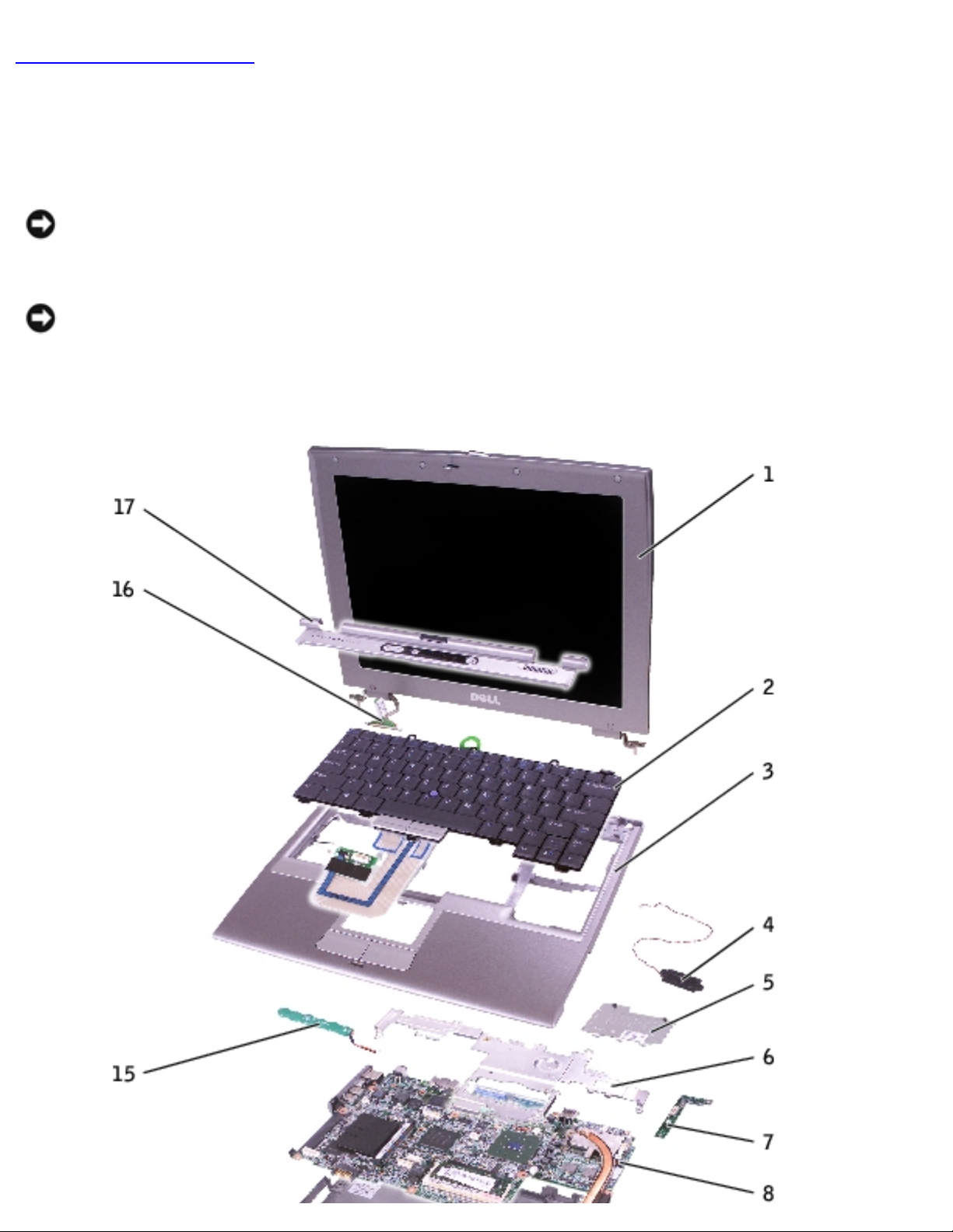
System Components
NOTICE: Only a certified service technician should perform repairs on your
computer. Damage due to servicing that is not authorized by Dell is not covered
by your warranty.
NOTICE: Unless otherwise noted, each procedure in this document assumes
that a part can be replaced by performing the removal procedure in reverse
order.
file:///F|/Service%20Manuals/Dell/Latitude/d400/system.htm (1 of 2) [2/28/2004 8:06:09 AM]
Page 17
System Components:
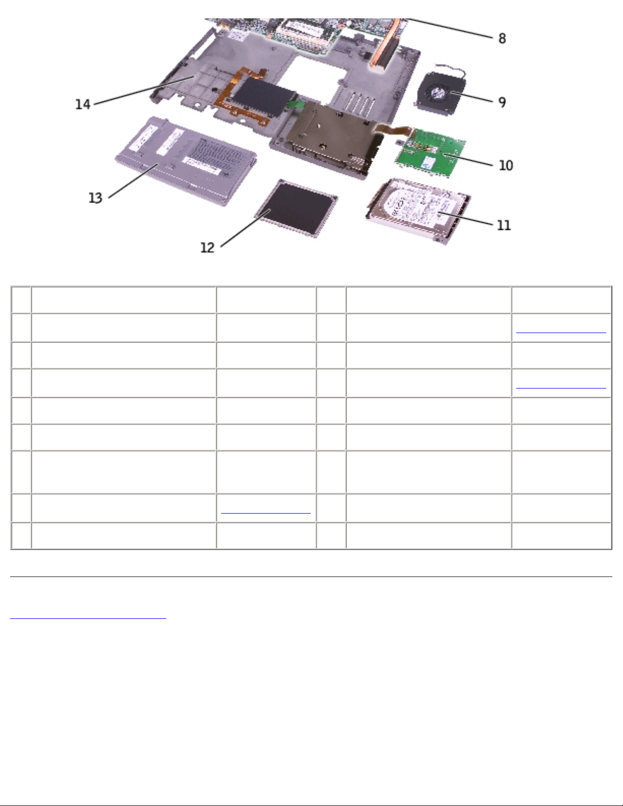
1
display P1291
10
smart card reader 0X740
2
keyboard P1290
11
hard drive
See Mini RSL
3
palm rest 4U782
12
memory module cover P0777
4
speaker 4U782
13
battery
See Mini RSL
5
DIMM1 cover 2X386
14
computer base D2389
6
metal shield 2X370
15
reserve battery 3U490
7
Hard drive controller
card
2X372
16
display connector 2X241
8
system board
See Mini RSL
17
center control cover 5U447
9
fan 6U568
Back to Contents Page
file:///F|/Service%20Manuals/Dell/Latitude/d400/system.htm (2 of 2) [2/28/2004 8:06:09 AM]
Page 18
Keyboard:
Back to Contents Page
Keyboard
Removing the Keyboard
Installing the Keyboard
Removing the Keyboard
CAUTION: Before performing the following procedures, read the safety
instructions in your System Information Guide.
NOTICE: To avoid electrostatic discharge, ground yourself by using a wrist
grounding strap or by periodically touching an unpainted metal surface (such as
the back panel) on the computer.
1. Follow the instructions in "
Preparing to Work Inside the Computer" to remove
the battery and prepare the computer for work.
2. Open the display approximately 180 degrees.
3. Use a plastic scribe or, if a plastic scribe is not available, carefully use a small
flat-blade screwdriver to lift the notched right edge of the center control cover,
and pry the cover loose from the bottom case.
file:///F|/Service%20Manuals/Dell/Latitude/d400/keyboard.htm (1 of 5) [2/28/2004 8:06:10 AM]
Page 19

Keyboard:
1
center control cover 5U447
4. Remove the two M2 x 5-mm screws from the top of the keyboard.
5. Use the pull-tab to pull the keyboard up and out (toward the display) of the
bottom case.
file:///F|/Service%20Manuals/Dell/Latitude/d400/keyboard.htm (2 of 5) [2/28/2004 8:06:10 AM]
Page 20

Keyboard:
1
keyboard P1290
2
keyboard pull-tab
3
M2 x 5-mm screws (2) 1428U
4
securing tabs (5)
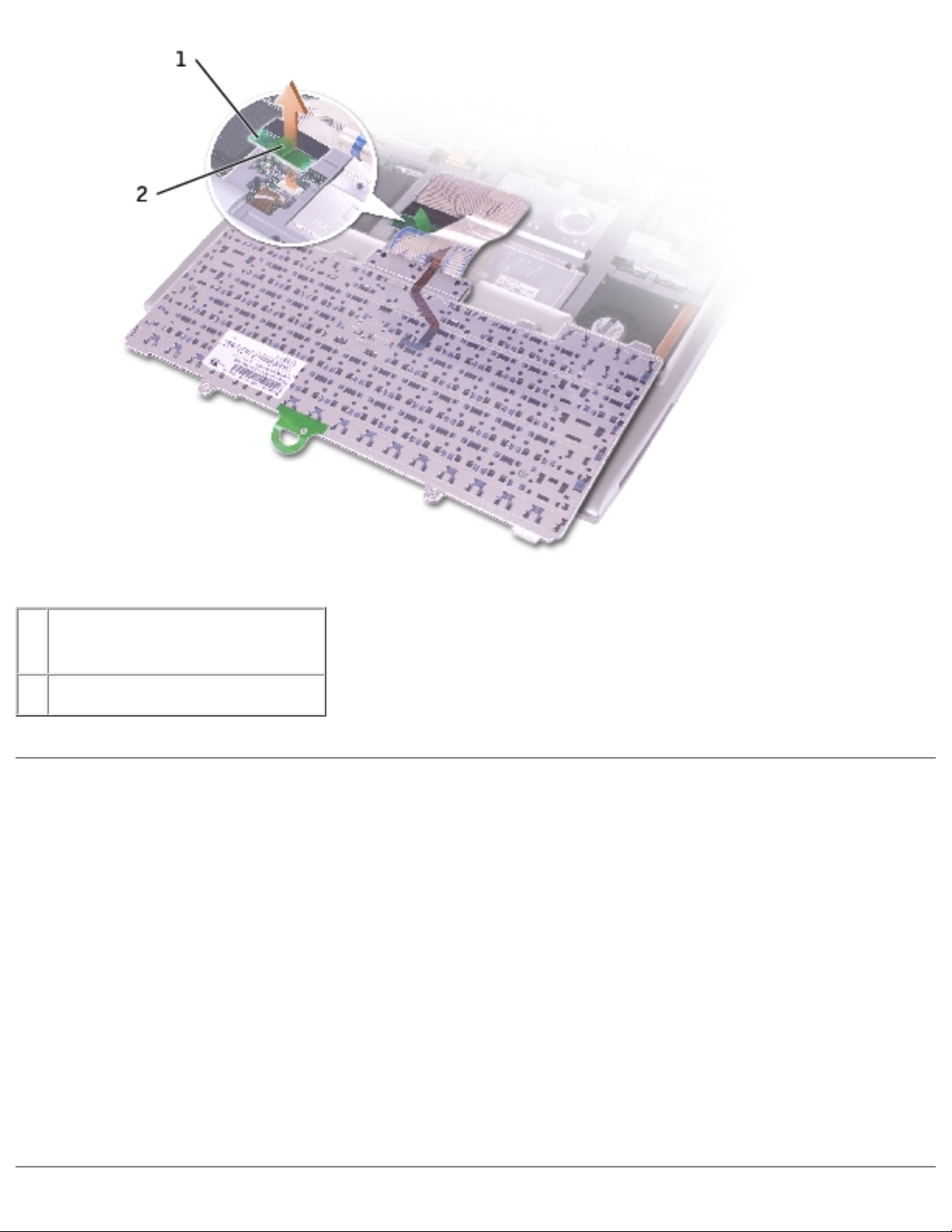
6. Rest the keyboard face down on the palm rest.
7. Pull straight up on the pull-tab that is attached to the keyboard connector to
disconnect the connector from the interface connector on the system board.
file:///F|/Service%20Manuals/Dell/Latitude/d400/keyboard.htm (3 of 5) [2/28/2004 8:06:10 AM]
Page 21
Keyboard:
1
pull-tab on keyboard
connector
2
keyboard connector
Installing the Keyboard
1. Connect the keyboard connector to the interface connector on the system board.
2. Insert the five securing tabs on the keyboard into their respective slots in the
palm rest.
3. Replace the two screws at the top of the keyboard.
4. Replace the center control cover and snap it down starting on the left side and
working to the right side so that it is flush with the palm rest.
file:///F|/Service%20Manuals/Dell/Latitude/d400/keyboard.htm (4 of 5) [2/28/2004 8:06:10 AM]
Page 22

Keyboard:
Back to Contents Page
file:///F|/Service%20Manuals/Dell/Latitude/d400/keyboard.htm (5 of 5) [2/28/2004 8:06:10 AM]
Page 23

Memory:
Back to Contents Page
Memory
Installing a Memory Module Under the Memory Module/Modem Cover
Installing a Memory Module Under the Keyboard
CAUTION: Before performing the following procedures, read the safety
instructions in your System Information Guide.
NOTICE: To avoid electrostatic discharge, ground yourself by using a wrist
grounding strap or by periodically touching an unpainted metal surface (such as
the back panel) on the computer.
1. Follow the instructions in "
Preparing to Work Inside the Computer" to remove
the battery and prepare the computer for work.
2. Continue to the appropriate section:
● "Installing a Memory Module Under the Memory Module/Modem Cover"
● "Installing a Memory Module Under the Keyboard"
Installing a Memory Module Under the
Memory Module/Modem Cover
1. Turn the computer over, loosen the captive screws on the memory
module/modem cover, and then remove the cover.
file:///F|/Service%20Manuals/Dell/Latitude/d400/memory.htm (1 of 7) [2/28/2004 8:06:11 AM]
Page 24

Memory:
1 captive screws (2)
2 memory module/modem cover P0777
NOTICE: To prevent damage to the memory module connector, do not use
tools to spread the memory-module securing clips.
2. If you are replacing a memory module, remove the existing module:
a. Use your fingertips to carefully spread apart the securing clips on each end
of the memory module connector until the module pops up.
b. Remove the module from the connector.
file:///F|/Service%20Manuals/Dell/Latitude/d400/memory.htm (2 of 7) [2/28/2004 8:06:11 AM]
Page 25

Memory:
1 memory module
See Mini RSL
2 securing clips (2)
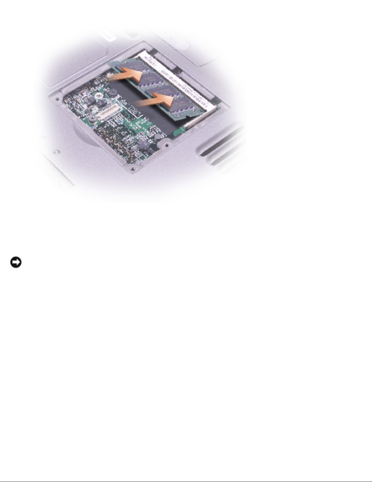
3. Ground yourself and install the new memory module:
a. Align the notch in the module edge connector with the tab in the connector
slot.
b. Slide the module firmly into the slot at a 45-degree angle, and rotate the
module down until it clicks into place. If you do not feel the click, remove
the module and reinstall it.
NOTE: If the memory module is not installed properly, the computer may not
boot properly. No error message indicates this failure.
file:///F|/Service%20Manuals/Dell/Latitude/d400/memory.htm (3 of 7) [2/28/2004 8:06:11 AM]
Page 26
Memory:
4. Replace the cover.
NOTICE: If the cover is difficult to close, remove the module and reinstall it.
Forcing the cover to close may damage your computer.
5. Insert the battery into the battery bay, or connect the AC adapter to your
computer and an electrical outlet.
6. Turn on the computer.
As the computer boots, it detects the additional memory and automatically updates
the system configuration information.
To confirm the amount of memory installed in the computer:
● In the Microsoft® Windows® XP operating system, click the Start button, click
Help and Support, and then click Computer Information.
● In Windows 2000, right-click the My Computer icon on your desktop, and then
click the General tab.
file:///F|/Service%20Manuals/Dell/Latitude/d400/memory.htm (4 of 7) [2/28/2004 8:06:11 AM]
Page 27

Memory:
Installing a Memory Module Under the
Keyboard
1. Remove the keyboard.
2. Loosen the two captive screws in the cover labeled "DIMM1."
1
captive screws (2)
2
DIMM1 cover 2X386
3
memory module
See Mini RSL
file:///F|/Service%20Manuals/Dell/Latitude/d400/memory.htm (5 of 7) [2/28/2004 8:06:11 AM]
Page 28

Memory:
4
securing clips (2)
5
securing tabs (3)
NOTICE: To prevent damage to the memory module connector, do not use
tools to spread the memory-module securing clips.
3. If you are replacing a memory module, remove the existing module:
a. Use your fingertips to carefully spread apart the securing clips on each end
of the memory module connector until the module pops up.
b. Remove the module from the connector.
4. Ground yourself and install the new memory module:
a. Align the notch in the module edge connector with the tab in the connector
slot.
b. Slide the module firmly into the slot at a 45-degree angle, and rotate the
module down until it clicks into place. If you do not feel the click, remove
the module and reinstall it.
NOTE: If the memory module is not installed properly, the computer may not
boot properly. No error message indicates this failure.
5. Insert the three securing tabs on the DIMM1 cover into the notches above the
memory module connector and tighten the captive screws.
NOTICE: If the DIMM1 cover is difficult to replace, remove the module and
reinstall it. Forcing the cover to close may damage your computer.
6.
Replace the keyboard.
7. Insert the battery into the battery bay, or connect the AC adapter to your
computer and an electrical outlet.
8. Turn on the computer.
As the computer boots, it detects the additional memory and automatically updates
file:///F|/Service%20Manuals/Dell/Latitude/d400/memory.htm (6 of 7) [2/28/2004 8:06:11 AM]
Page 29

Memory:
the system configuration information. You may have to press <F1> to acknowledge
that you have added additional memory.
To confirm the amount of memory installed in the computer:
● In Windows XP, click the Start button, click Help and Support, and then click
Computer Information.
● In Windows 2000, right-click the My Computer icon on your desktop, and then
click the General tab.
Back to Contents Page
file:///F|/Service%20Manuals/Dell/Latitude/d400/memory.htm (7 of 7) [2/28/2004 8:06:11 AM]
Page 30

Mini PCI Card:
Back to Contents Page
Mini PCI Card
CAUTION: Before performing the following procedures, read the safety
instructions in your System Information Guide.
NOTICE: To avoid electrostatic discharge, ground yourself by using a wrist
grounding strap or by periodically touching an unpainted metal surface (such as
the back panel) on the computer.
1. Follow the instructions in "
Preparing to Work Inside the Computer" to remove
the battery and prepare the computer for work.
2.
Remove the keyboard.
3. If a Mini PCI card is not already installed, go to
step 4. If you are replacing a
Mini PCI card, remove the existing card:
a. Disconnect the Mini PCI card from the attached cables.
file:///F|/Service%20Manuals/Dell/Latitude/d400/minipci.htm (1 of 4) [2/28/2004 8:06:12 AM]
Page 31

Mini PCI Card:
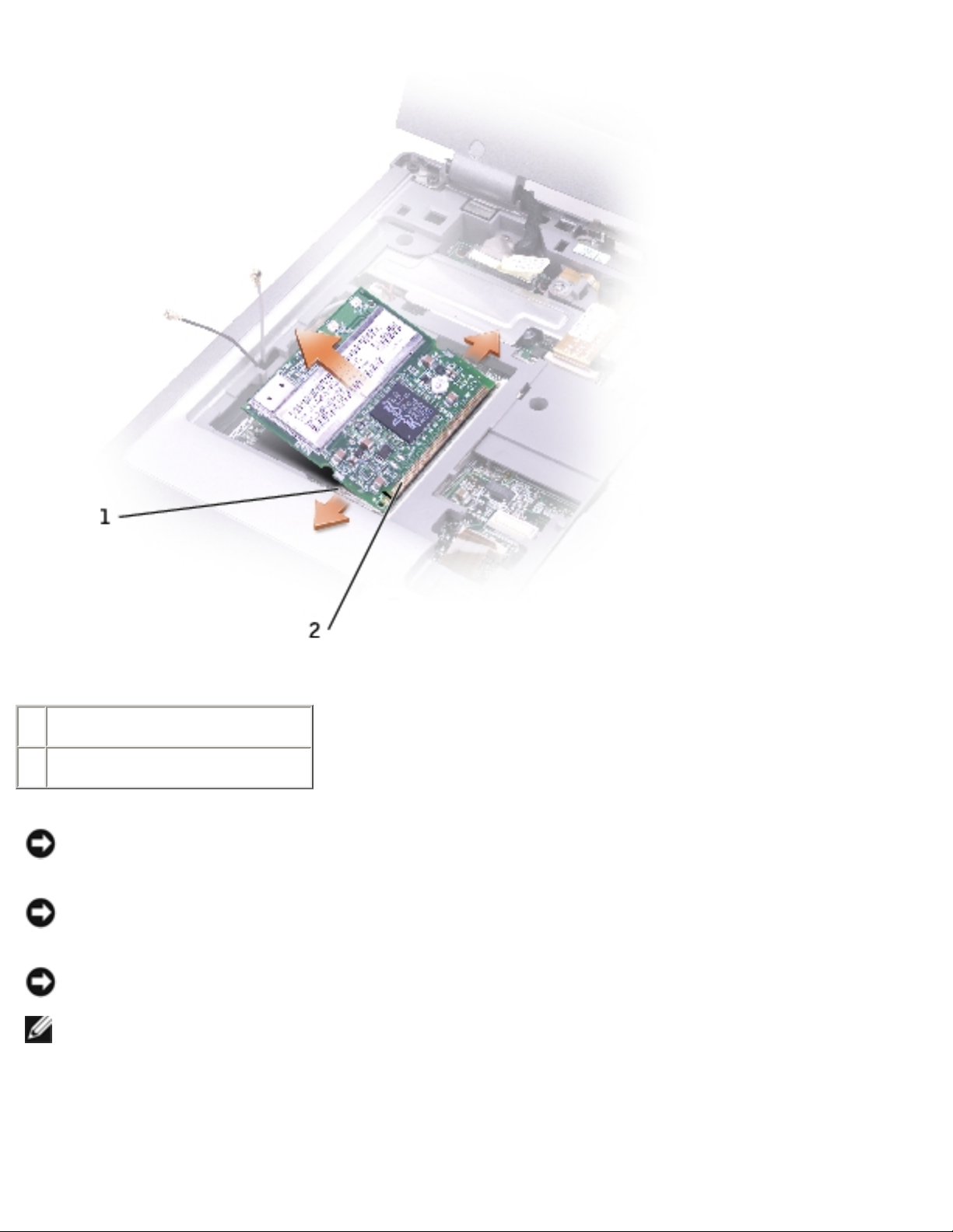
1 antenna cables (2)
2 Mini PCI card 9Y200
3X548
J0846
b. Release the Mini PCI card by spreading the metal securing tabs until the
card pops up slightly.
c. Lift the Mini PCI card out of its connector.
file:///F|/Service%20Manuals/Dell/Latitude/d400/minipci.htm (2 of 4) [2/28/2004 8:06:12 AM]
Page 32
Mini PCI Card:
1 securing tabs (2)
2 Mini PCI card connector
NOTICE: To avoid damaging the Mini PCI card, never place cables on top of or
under the card.
NOTICE: The connectors are keyed to ensure correct insertion. If you feel
resistance, check the connectors and realign the card.
NOTICE: Handle the antenna cables with care because they are very fragile.
NOTE: If a Mini PCI card was not already installed, remove the foam that
secures the antenna cables before you install the card.
4. Align the Mini PCI card with the connector at a 45-degree angle, and press the
Mini PCI card into the connector until you feel a click.
file:///F|/Service%20Manuals/Dell/Latitude/d400/minipci.htm (3 of 4) [2/28/2004 8:06:12 AM]
Page 33

Mini PCI Card:
5. Connect the antenna cables to the Mini PCI card, with the white cable in the Mini
PCI connector closer to the palm rest, and the black cable in the Mini PCI card
connector closer to the display.
6. Replace the keyboard.
Back to Contents Page
file:///F|/Service%20Manuals/Dell/Latitude/d400/minipci.htm (4 of 4) [2/28/2004 8:06:12 AM]
Page 34

Modem:
Back to Contents Page
Modem
CAUTION: Before performing the following procedures, read the safety
instructions in your System Information Guide.
NOTICE: To avoid electrostatic discharge, ground yourself by using a wrist
grounding strap or by periodically touching an unpainted metal surface (such as
the back panel) on the computer.
1. Follow the instructions in "
Preparing to Work Inside the Computer" to remove
the battery and prepare the computer for work.
NOTICE: Handle components and cards by their edges, and avoid touching pins
and contacts. Ground yourself by touching a metal connector on the back of the
computer. Continue to ground yourself periodically during this procedure.
2. Turn the computer over, loosen the captive screws on the memory
module/modem cover, and then remove the cover.
file:///F|/Service%20Manuals/Dell/Latitude/d400/modem.htm (1 of 3) [2/28/2004 8:06:12 AM]
Page 35

Modem:
1
M2 x 5-mm screw 1428U
2
pull-tab
3
modem cable
3. If a modem is not already installed, go to
step 4. If you are replacing a modem,
remove the existing modem:
a. Remove the M2 x 5-mm screw securing the modem to the system board,
and set it aside.
b. Pull straight up on the attached pull-tab to lift the modem out of its
connector on the system board, and disconnect the modem cable.
4. Connect the modem cable to the modem.
NOTICE: The cable connectors are keyed for correct insertion; do not force the
connections.
5. Align the modem with the screw hole, and press the modem into the connector
on the system board.
file:///F|/Service%20Manuals/Dell/Latitude/d400/modem.htm (2 of 3) [2/28/2004 8:06:12 AM]
Page 36

Modem:
6. Install the screw to secure the modem to the system board.
7. Replace the modem cover.
Back to Contents Page
file:///F|/Service%20Manuals/Dell/Latitude/d400/modem.htm (3 of 3) [2/28/2004 8:06:12 AM]
Page 37

Hard Drive:
Back to Contents Page
Hard Drive
Removing the Hard Drive
Installing the Hard Drive
Removing the Interposer
Replacing the Interposer
Removing the Hard Drive
CAUTION: If you remove the hard drive from the computer when the
drive is warm, do not touch the metal housing of the hard drive.
CAUTION: Before performing the following procedures, read the safety
instructions in your System Information Guide.
NOTICE: To avoid electrostatic discharge, ground yourself by using a wrist
grounding strap or by periodically touching an unpainted metal surface (such as
the back panel) on the computer.
NOTICE: To prevent data loss, turn off your computer before removing the
hard drive. Do not remove the hard drive while the computer is on, in standby
mode, or in hibernate mode.
NOTICE: Hard drives are extremely fragile; even a slight bump can damage the
drive.
NOTE: Dell does not guarantee compatibility or provide support for hard drives
from sources other than Dell.
To remove the hard drive in the hard drive bay:
1. Follow the instructions in "
Preparing to Work Inside the Computer" to remove
the battery and prepare the computer for work.
2. Turn the computer over, and remove the two M3 x 3-mm screws.
file:///F|/Service%20Manuals/Dell/Latitude/d400/hdd.htm (1 of 5) [2/28/2004 8:06:13 AM]
Page 38

Hard Drive:
NOTICE: When the hard drive is not in the computer, store it in protective,
antistatic packaging. See "Protecting Against Electrostatic Discharge" in your
System Information Guide.
1
M3 x 3-mm screws (2) 2864D
2
hard drive
See Mini RSL
3. Slide the hard drive out of the computer.
Installing the Hard Drive
1. Remove the new drive from its packaging.
Save the original packaging for storing or shipping the hard drive.
file:///F|/Service%20Manuals/Dell/Latitude/d400/hdd.htm (2 of 5) [2/28/2004 8:06:13 AM]
Page 39

Hard Drive:
2. Slide the hard drive into the bay until it is fully seated.
3. Replace and tighten the two M3 x 3-mm screws.
4. Use the Operating System CD to install the operating system for your computer.
5. Use the Drivers and Utilities CD to install the drivers and utilities for your
computer.
Removing the Interposer
1. Follow the instructions in "Preparing to Work Inside the Computer" to remove
the battery and prepare the computer for work.
2. Remove the
hard drive.
3. Remove the two M3 x 3-mm screws from the side of the hard drive, and remove
the hard drive carrier.
file:///F|/Service%20Manuals/Dell/Latitude/d400/hdd.htm (3 of 5) [2/28/2004 8:06:13 AM]
Page 40

Hard Drive:
1
M3 x 3-mm screws (2) 2864D
2
hard drive carrier 7X499
4. Carefully remove the interposer by pulling it straight off the hard drive.
1
interposer 8267R
Replacing the Interposer
NOTICE: Use firm and even pressure to slide the drive into place. If you use
excessive force, you may damage the connector.
1. Attach the hard drive carrier to the new hard drive, and replace the two M3 x 3mm screws.
2. Carefully attach the interposer from the old hard drive by pushing it straight
onto the hard drive. Ensure that the pins are oriented correctly. When the
file:///F|/Service%20Manuals/Dell/Latitude/d400/hdd.htm (4 of 5) [2/28/2004 8:06:13 AM]
Page 41

Hard Drive:
interposer is attached correctly, four extra pins are on one side.
1
interposer 8267R
3. Install the
hard drive.
Back to Contents Page
file:///F|/Service%20Manuals/Dell/Latitude/d400/hdd.htm (5 of 5) [2/28/2004 8:06:13 AM]
Page 42

Docking Doors:
Back to Contents Page
Docking Doors
Removing the Docking Doors
Installing the Docking Doors
Removing the Docking Doors
CAUTION: Before performing the following procedures, read the safety
instructions in your System Information Guide.
NOTICE: To avoid electrostatic discharge, ground yourself by using a wrist
grounding strap or by periodically touching an unpainted metal surface (such as
the back panel) on the computer.
1. Follow the instructions in "
Preparing to Work Inside the Computer" to remove
the battery and prepare the computer for work.
2. Gently bend the docking doors and lift them away from the computer base.
file:///F|/Service%20Manuals/Dell/Latitude/d400/dockdoor.htm (1 of 3) [2/28/2004 8:06:14 AM]
Page 43

Docking Doors:
1
docking doors 8X516
Installing the Docking Doors
Slide the side of the docking doors with the spring over the longer posts.
file:///F|/Service%20Manuals/Dell/Latitude/d400/dockdoor.htm (2 of 3) [2/28/2004 8:06:14 AM]
Page 44

Docking Doors:
1
docking doors with spring 8X516
2
longer post
Back to Contents Page
file:///F|/Service%20Manuals/Dell/Latitude/d400/dockdoor.htm (3 of 3) [2/28/2004 8:06:14 AM]
Page 45

Bluetooth™:
Back to Contents Page
Bluetooth™
CAUTION: Before performing the following procedures, read the safety
instructions in your System Information Guide.
NOTICE: To avoid electrostatic discharge, ground yourself by using a wrist
grounding strap or by periodically touching an unpainted metal surface (such as
the back panel) on the computer.
1. Follow the instructions in "
Preparing to Work Inside the Computer" to remove
the battery and prepare the computer for work.
2. Turn the computer over, loosen the captive screw in the Bluetooth module
cover, and remove the cover.
1
Bluetooth module cover 0X737
file:///F|/Service%20Manuals/Dell/Latitude/d400/blue.htm (1 of 3) [2/28/2004 8:06:15 AM]
Page 46

Bluetooth™:
2
captive screw
3
battery bay
3. Remove the existing module:
a. Pull the Bluetooth module out of the slot.
b. Disconnect the cable from the module.
1
Bluetooth connector
2
Bluetooth module (front) 2U381
4. Ensure that the front of the Bluetooth module (silver) is facing outward, and
connect the cable to the module.
5. Insert the module into the slot.
6. Replace the cover and tighten the captive screw.
file:///F|/Service%20Manuals/Dell/Latitude/d400/blue.htm (2 of 3) [2/28/2004 8:06:15 AM]
Page 47

Bluetooth™:
Back to Contents Page
file:///F|/Service%20Manuals/Dell/Latitude/d400/blue.htm (3 of 3) [2/28/2004 8:06:15 AM]
Page 48
Display:
Back to Contents Page
Display
Removing the Display Assembly
Replacing the Display Latch
Removing the Display Assembly
CAUTION: Before performing the following procedures, read the safety
instructions in your System Information Guide.
NOTICE: To avoid electrostatic discharge, ground yourself by using a wrist
grounding strap or by periodically touching an unpainted metal surface (such as
the back panel) on the computer.
1. Follow the instructions in "
Preparing to Work Inside the Computer" to remove
the battery and prepare the computer for work.
2. Remove the battery.
3. Remove the
hard drive.
4. Remove the
center control cover.
5. Remove the two M2.5 x 6-mm screws next to each hinge.
file:///F|/Service%20Manuals/Dell/Latitude/d400/display.htm (1 of 4) [2/28/2004 8:06:16 AM]
Page 49

Display:
1
display-feed flex cable
2
M2.5 x 6-mm screws (6) 4911U
3
display-feed flex cable hold-down board
4
pull-tab
6. Remove the two M2.5 x 6-mm screws from the display-feed flex cable holddown board.
7. Use the pull-tab to disconnect the display-feed flex cable from its connector on
the system board.
8. Move the display assembly to an upright position and pull it up out of the
computer.
Replacing the Display Latch
file:///F|/Service%20Manuals/Dell/Latitude/d400/display.htm (2 of 4) [2/28/2004 8:06:16 AM]
Page 50
Display:
CAUTION: Before performing the following procedures, read the safety
instructions in your System Information Guide.
NOTICE: To avoid electrostatic discharge, ground yourself by using a wrist
grounding strap or by periodically touching an unpainted metal surface (such as
the back panel) on the computer.
To replace the display latch, you must remove the whole bezel.
1. Follow the instructions in "
Preparing to Work Inside the Computer."
2. Remove the
hard drive.
3. Remove the
keyboard.
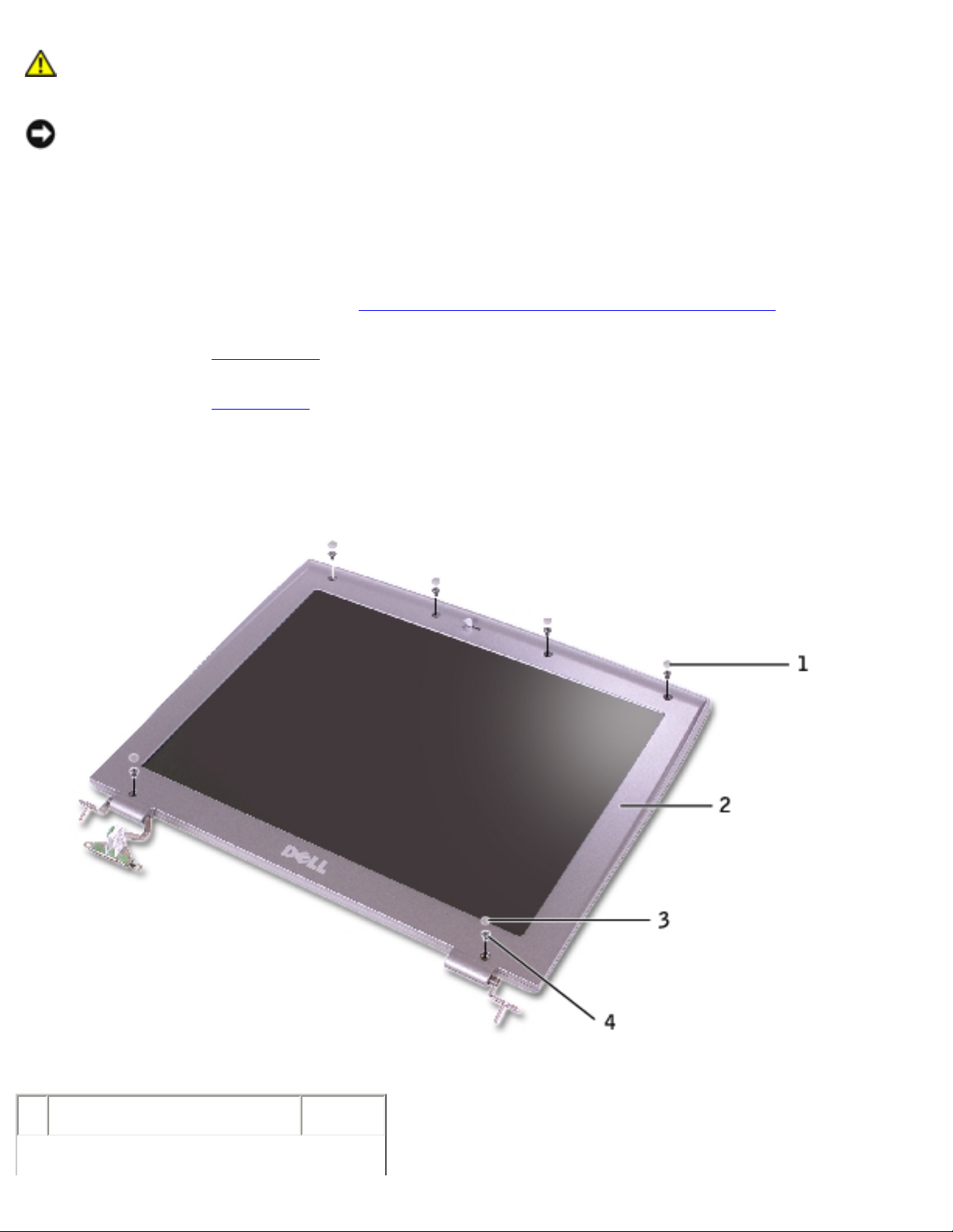
4. Open the display 180 degrees, and remove the two rubber screw covers, four
rubber screw bumpers, and the six M2.5 x 4-mm screws that secure the bezel.
1
rubber screw bumpers 6U549
file:///F|/Service%20Manuals/Dell/Latitude/d400/display.htm (3 of 4) [2/28/2004 8:06:16 AM]
Page 51

Display:
2
bezel
3
rubber screw covers 2U940
4
M2.5 x 4-mm screws 7116P
5. Use your fingers to carefully pry around the perimeter of the bezel until the
bezel separates from the display assembly.
6. Remove the two display latch screws, and remove the display latch.
1
M2 x 1.8-mm screws (2) 5H953
2
display latch
NOTICE: When you replace the bezel, ensure that the display cable is routed
correctly.
Back to Contents Page
file:///F|/Service%20Manuals/Dell/Latitude/d400/display.htm (4 of 4) [2/28/2004 8:06:16 AM]
Page 52

Palm Rest:
Back to Contents Page
Palm Rest
CAUTION: Before performing the following procedures, read the safety
instructions in your System Information Guide.
NOTICE: To avoid electrostatic discharge, ground yourself by using a wrist
grounding strap or by periodically touching an unpainted metal surface (such as
the back panel) on the computer.
1. Follow the instructions in "
Preparing to Work Inside the Computer" to remove
the battery and prepare the computer for work.
2. Remove the
hard drive.
3. Remove the
keyboard.
NOTICE: You must remove the display assembly before you remove the palm
rest; the display hinges pass through the back of the palm rest.
4. Remove the
display.
5. Turn the computer over and remove the nine M2.5 x 6-mm screws.
file:///F|/Service%20Manuals/Dell/Latitude/d400/palmrest.htm (1 of 5) [2/28/2004 8:06:17 AM]
Page 53

Palm Rest:
1
M2 x 1.8-mm screws (2) 5H953
2
M 2.5 x 6-mm screws (9) 4911U
6. Remove the two M2 x 1.8-mm screws located inside the battery bay.
7. Turn the computer over and remove the four M2.5 x 6-mm screws.
file:///F|/Service%20Manuals/Dell/Latitude/d400/palmrest.htm (2 of 5) [2/28/2004 8:06:17 AM]
Page 54

Palm Rest:
1
M2.5 x 6-mm screws (4) 4911U
8. Disconnect the speaker connector, and remove the speaker cable.
file:///F|/Service%20Manuals/Dell/Latitude/d400/palmrest.htm (3 of 5) [2/28/2004 8:06:17 AM]
Page 55

Palm Rest:
1
ZIF connector
2
speaker connector
9. Pull up on the palm rest connector tab, and disconnect the ZIF connector from
the system board.
10. Disengage the four battery bay tabs.
file:///F|/Service%20Manuals/Dell/Latitude/d400/palmrest.htm (4 of 5) [2/28/2004 8:06:17 AM]
Page 56

Palm Rest:
11. Lift the palm rest away.
Back to Contents Page
file:///F|/Service%20Manuals/Dell/Latitude/d400/palmrest.htm (5 of 5) [2/28/2004 8:06:17 AM]
Page 57

Cooling Fan:
Back to Contents Page
Cooling Fan
CAUTION: Before performing the following procedures, read the safety
instructions in your System Information Guide.
NOTICE: To avoid electrostatic discharge, ground yourself by using a wrist
grounding strap or by periodically touching an unpainted metal surface (such as
the back panel) on the computer.
1. Follow the instructions in "
Preparing to Work Inside the Computer" to remove
the battery and prepare the computer for work.
2. Remove any installed
memory modules, smart card, modem, or PC Card.
3. Remove the
hard drive.
4. Remove the
keyboard.
5. Remove the
display.
6. Remove the
palm rest.
7. Remove the fan cable from the fan extender cable that runs under the system
board.
file:///F|/Service%20Manuals/Dell/Latitude/d400/fan.htm (1 of 2) [2/28/2004 8:06:17 AM]
Page 58

Cooling Fan:
1
fan cable
2
M2 x 5-mm screws (3) 1428U
8. Remove the three M2 x 5-mm screws that secure the cooling fan.
9. Lift out the cooling fan.
Back to Contents Page
file:///F|/Service%20Manuals/Dell/Latitude/d400/fan.htm (2 of 2) [2/28/2004 8:06:17 AM]
 Loading...