

Page 1

Dell™ Latitude™ CPx H -Series/J-Series User's Guide
Preface
Introduction
Setup and Operation
Powering Your Computer
Intel SpeedStep Options
Traveling With Your Computer
Drivers
Customizing Your Computer
Removing and Replacing Parts
Troubleshooting Your Computer
Technical Specifications
Getting Help
Information in this document is subject to change without notice.
© 1999 – 2000 Dell Computer Corporation. All rights reserved.
Reproduction in any manner whatsoever without the written permission of Dell Computer Corporation is strictly forbidden.
Trademarks used in this text: Dell, Latitude, Dimension, Inspiron, Optiplex, ExpressCharge , HyperCool, and DellWare are
trademarks of Dell Computer Corporation; Microsoft, Windows, Windows NT , and MS-DOS are registered trademarks of Microsoft
Corporation; Intel and Pentium are registered trademarks and SpeedStep is trademark of Intel Corporation. As an ENERGY STAR
partner, Dell Computer Corporation has determined that this product meets the ENERGY STAR guidelines for energy efficiency.
Other trademarks and trade names may be used in this document to refer to either the entities claiming the marks and names or
their products. Dell Computer Corporation disclaims any proprietary interest in trademarks and trade names other than its own.
This product incorporates copyright protection technology that is protected by method claims of certain U.S. patents and other
intellectual property rights owned by Macrovision Corporation and other rights owners. Use of this copyright protection technology
must be authorized by Macrovision Corporation and is intended for home and other limited viewing uses only unless otherwise
authorized by Macrovision Corporation. Reverse engineering or disassembly is prohibited.
Model PPX
Initial release: 15 Nov 1999
Last revised: 28 Aug 2000
Page 2

Back to Contents Page
Preface: Dell™ Latitude™ CPx H-Series/J-Series User's Guide
About This Guide Notational Conventions
Warranty and Return Policy Information Typographical Conventions
Other Documents You May Need
About This Guide
This guide is intended for anyone who uses the Dell Latitude CPx H-Series/J-Series portable computers. It
can be used by both first-time and experienced computer users who want to learn about the features of the
computer. This guide also provides basic troubleshooting procedures and instructions for using the Dell
Diagnostics to test your computer and its components. The sections are summarized as follows:
"Introduction" — overview of the computer features and available upgrades
"Setup and Operation" — instructions on operating your computer
"Powering Your Computer" — instructions and options on how to power your computer
"Traveling With Your Computer" — suggestions on how to travel safely with your computer
"Drivers" — instructions on how to install driver software on your computer
"Customizing Your Computer" — instructions on accessing the System Setup program, power
management software, and the Suspend-to-Disk utility, all of which allow you to change system
settings affecting your computer's power conservation features
"Removing and Replacing Parts" — instructions on how to remove and install hard-disk drives and
memory modules
"Troubleshooting Your Computer" — initial checks and procedures that can be used to solve basic
computer problems, general guidelines on analyzing software problems, messages, and beep codes
"Technical Specifications" — reference material about the details of your computer
"Getting Help" — help tools Dell provides to assist you if you have a problem with the computer and
explains how and when to call Dell for technical assistance
Warranty and Return Policy Information
Dell Computer Corporation ("Dell") manufactures its hardware products from parts and components that are
new or equivalent to new in accordance with industry-standard practices.
For information about the Dell warranty and return policy, see the System Information guide that came with
your computer.
Page 3

Other Documents You May Need
other options that appear on the monitor screen or display. They are presented in bold.
Besides this User's Guide, the following documentation is included with your computer:
NOTE: Documentation updates are sometimes included with your computer to describe changes to
your computer or software. Always read these updates before consulting any other documentation
because the updates contain the latest information.
An operating system Setup Guide, which describes how to set up the operating system installed on
your Dell computer.
Operating system documentation is included if you ordered your operating system from Dell. This
documentation describes how to configure and use your operating system software.
Documentation is included with any options you purchase separately from your computer. This
documentation includes information that you need to configure and install these options in your Dell
computer.
"Readme" files may be installed on your hard-disk drive to provide last-minute updates about technical
changes to your computer or advanced technical reference material intended for experienced users or
technicians.
Notational Conventions
The following subsections list notational conventions used in this document.
Notes, Notices, and Cautions
Throughout this guide, blocks of text may be accompanied by an icon and printed in bold type or in italic
type. These blocks are notes, notices, and cautions, and they are used as follows:
NOTE: A NOTE indicates important information that helps you make better use of your computer.
NOTICE: A NOTICE indicates either potential damage to hardware or loss of data and tells you how
to avoid the problem.
CAUTION: A CAUTION indicates a potentially hazardous situation which, if not avoided, may
result in minor or moderate injury.
Typographical Conventions
The following list defines (where appropriate) and illustrates typographical conventions used as visual cues
for specific elements of text throughout this document:
Interface components are window titles, button and icon names, menu names and selections, and
Page 4

Example: Click OK.
Keycaps, the labeling that appears on the keys on a keyboard, are enclosed in angle brackets.
Example: <Enter>
Key combinations are series of keys to be pressed simultaneously (unless otherwise indicated) to
perform a single function.
Example: <Ctrl><Alt><Enter>
Commands presented in lowercase bold are for reference purposes only and are not intended to be
typed at that particular point in the discussion.
Example: "Use the setup command to . . . ."
In contrast, commands presented in the Courier New font are intended to be typed as part of an
instruction.
Example: "Type format to format the diskette in drive A."
Filenames and directory names are presented in lowercase bold.
Examples: autoexec.bat and c:\windows
Syntax lines consist of a command and all its possible parameters. Commands are displayed in
lowercase bold; variable parameters (those for which you substitute a value) are displayed in lowercase
italics; constant parameters are displayed in lowercase bold. The brackets indicate items that are
optional.
Example: del [drive:] [[path]filename] [/p]
Command lines consist of a command and may include one or more of the command's possible
parameters. Command lines are presented in the Courier New font.
Example: del c:\myfile.doc
Screen text is text that appears on the screen of your display or external monitor. It can be a system
message, for example, or it can be text that you are instructed to type as part of a command (referred
to as a command line). Screen text is presented in the Courier New font.
Example: The following message appears on your screen:
No boot device available
Variables are symbols for which you substitute a value. They are presented in italics.
Example: module n (where n represents the memory module number)
Page 5

Back to Contents Page
Page 6
Back to Contents Page
Introduction: Dell™ Latitude™ CPx H -Series/J-Series User's Guide
Overview Available Options
Features Getting Help
Overview
The Dell Latitude CPx H-Series/J-Series portable computers are expandable multimedia systems using the latest Intel® Mobile
Pentium® technology. In addition, the J-Series supports Intel SpeedStep™ technology. The CPx H-Series/J-Series computers
include the Dell DualPoint integrated pointing device, which provides a touch pad and a track stick to control the cursor on the
display screen. This section describes the major hardware and software features of your computer. Figure 1
front and back view of the computer, respectively.
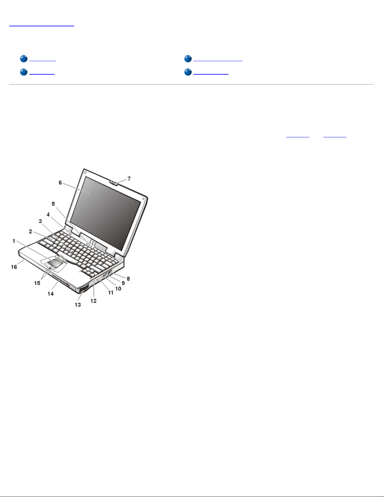
Figure 1. Front View of the Computer
and Figure 2 show the
1 Touch pad
2 Keyboard
3 Track stick
4 Power button
5 Keyboard status LEDs
6 Display
7 Display latch
8 Air intake
9 Internal modem connector (available only on CPt S-
Series)
10 S-Video connector
11 Audio jacks (3)
Page 7
12 Integrated microphone
13 Speaker
14 Modular bay
15 DualPoint buttons
16 Battery bay
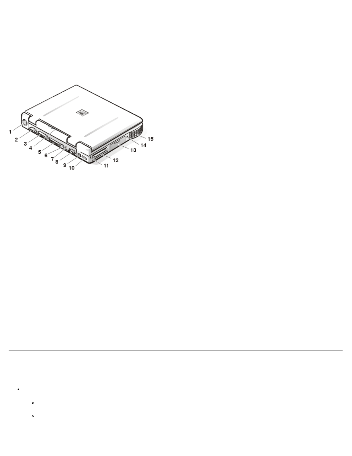
Figure 2. Back View of the Computer
1 Fan
2 Video connector
3 Parallel connector
4 Status indicator panel
5 Docking connector
6 USB connector
7 PS/2 connector
8 Serial connector
9 AC adapter connector
10 Infrared port
11 Security cable slot
12 PC Card slots (2)
13 Hard-disk drive
14 Security cable slot
15 Speaker
Features
Your Dell computer has the following features:
Full multimedia capability through the following standard features:
A 14.1-inch extended graphics array (XGA), thin film transistor (TFT) 1024 x 768 active-matrix color display.
A CD-ROM drive that can be used in the modular bay. When you unpack your computer, look for the CD-ROM drive in
the accessories box of the shipping carton.
Page 8

64-bit hardware-accelerated video support, with 8 megabytes (MB) of video memory.
Support for a zoomed video (ZV) PC Card in the lower PC Card connector.
used in some other batteries (such as watch batteries).
For H-Series computers, ESS Maestro 2E audio controller with hardware wavetable support and 3D surround sound.
For J-Series computers, ESS Maestro 3I audio controller with software wavetable support and 3D surround sound.
Three audio jacks for connecting external speakers or headphones, a microphone, and a record/playback device to
your computer.
Integrated microphone and two stereo speakers.
Accelerated graphics port (AGP) architecture that increases the computer's performance, particularly video
performance.
An ENERGY STAR® partner, Dell Computer Corporation has determined that this product meets the ENERGY STAR
guidelines for energy efficiency.
A modular bay that supports a DVD-ROM drive, CD-ROM drive, CD-RW drive, diskette drive, second battery, second
hard-disk drive, or SuperDisk LS-120 drive module. To make the computer as light as possible when you travel, use the
special travel module in the modular bay.
NOTE: Your computer was shipped with a diskette drive in the modular bay. For information on removing the
diskette drive and installing a different device in the bay, see "Modular Bay
."
A minimum of 32-MB synchronous dynamic random-access memory (SDRAM) module is standard. You can increase
memory up to 512 MB by installing combinations of 32-, 64-, 128-, 192-, or 256-MB SDRAM modules in the two memory
module sockets on the system board.
NOTE: Your computer is capable of supporting two 256-MB SDRAM modules for a total of 512 MB of memory.
Two power conservation modes — suspend mode and suspend-to-disk mode — that help you conserve battery power. If the
batteries run out of power, suspend-to-disk mode prevents data loss by copying all system data to the hard-disk drive and
turning off the computer.
Connectors for two 3.3-volt (V) or 5-V PC Cards. The lower PC Card connector supports ZV PC Cards.
NOTE: The PC Card controller supports the CardBus standard for 32-bit data transfer on the PC Card.
Hardware and software support for the Dell Latitude C/Port Family Advanced Port Replicator (APR) and the Dell Latitude
C/Dock Family Expansion Station.
A DualPoint integrated pointing device which includes both a touch pad and a track stick. These pointing devices are
positioned for both left- and right-handed users. The track stick is positioned in the keyboard to allow you to move the cursor
while keeping your fingers in a typing position. Two sets of left and right buttons, located above and below the touch pad,
mimic mouse buttons. You can also perform many pointing functions by tapping the touch pad or the track stick. Click-anddrag buttonless functions are also supported.
A lithium ion battery in the battery bay, with support for a second battery in the modular bay. The Dell ExpressCharge™
technology charges a single battery in approximately 1 hour (when the computer is off or in suspend mode).
NOTICE: Do not puncture or incinerate the battery. When your battery no longer holds a charge, call your local waste
disposal agency or environmental agency for advice on disposing of the computer's lithium ion battery. The lithium ion
technology used in the battery is significantly less hazardous to the environment than the lithium metal technology
Page 9

High-performance parallel and serial ports and a multipurpose Personal System/2 (PS/2) connector for attaching external
devices, a monitor connector for attaching an external monitor to your computer, and a Universal Serial Bus (USB) connector
that supports stand-alone and hub devices.
An infrared port that permits file transfer without the use of cable connections. The port is compatible with the Infrared Data
Association (IrDA) Standard 1.1 (Fast IR) and Standard 1.0 (Slow IR) for use with external devices.
Dell HyperCool™ an automatic thermal management system that uses a variable-speed fan, microprocessor speed changes,
and Intel's Remote Heat Exchanger technology to keep the system running at the optimum temperature.
CAUTION: Do not allow your Latitude portable computer to operate with the base resting directly on exposed skin.
With extended operation, heat can potentially build up in the base. Allowing sustained contact with the skin could
cause discomfort or, eventually, a burn.
The following software is included with your Dell computer:
The Microsoft® Windows® 95, Windows 98 Second Edition (SE), or Windows NT® 4.0, Windows 2000 or higher operating
system is installed on your hard-disk drive. For more information, see your operating system documentation.
For Latitude CPx J-Series computers, the Intel SpeedStep technology is installed on your hard-disk drive.
The System Setup program lets you view and change the system configuration. For more information, see "Using the System
Setup Program."
Dell Diagnostics for evaluating the computer's components and devices.
NOTE: If Dell did not install an operating system on your hard-disk drive, the drivers, system utilities, and diagnostics are
available separately from Dell. To order them, see "Getting Help
" for the appropriate telephone number in your location.
Available Options
As your computing requirements change, you can extend your computer's capabilities with a C/Port Family APR or C/Dock Family
Expansion Station. You can also install a hard-disk drive of larger capacity, increase system memory, and add functionality with PC
Cards. Dell also offers additional modules that you can install in the modular bay, including a second hard-disk drive, a DVD-ROM
drive, a CD-ROM drive, a CD-RW drive, an LS-120 drive module, and a second battery.
Dell offers the following devices and upgrade options:
C/Port Family APRs and C/Dock Family Expansion Stations
Additional batteries
External keyboards and a numeric keypad
External monitors
External pointing devices
External speakers, headphones, and microphones
Printers
Hard-disk drives
Second hard-disk drive for the modular bay
DVD-ROM drive modules
CD-RW drive modules
Second CD-ROM drive module
SuperDisk LS-120 drive modules
AC adapter
PC Cards
32-, 64-, 128-, 192-, and 256-MB memory modules
Carrying case
Instructions for connecting or installing these options are included in the upgrade kit you receive from Dell.
Page 10

Getting Help
If at any time you don't understand a procedure described in this guide, or if your computer does not perform as expected, Dell
provides a number of tools to help you. For more information on these help tools, see "Getting Help
Back to Contents Page
."
Page 11

Back to Contents Page
Setup and Operation: Dell™ Latitude™ CPx H -Series/J-Series
User's Guide
AC Adapter PC Cards
Batteries Modular Bay
CD-ROM, DVD-ROM, and CD-RW
Drives
Display Securing Your Computer
Diskette Drive Connecting External Devices
Keyboard I/O Connectors
Back to Contents Page
DualPoint Integrated Pointing Device
Page 12

Back to Contents Page
Powering Your Computer: Dell™ Latitude™ CPx H -Series/J-Series
User's Guide
AC Adapter
Power Management Settings
Batteries
Back to Contents Page
Page 13

Back to Contents Page
Intel® SpeedStep™ Options: Dell™ Latitude™ CPx H-Series/JSeries User's Guide
Using Intel SpeedStep
Using the Adjust Properties Option
Setting the Advanced Options
Using Intel SpeedStep
The Intel SpeedStep technology, included with the Latitude CPx J-Series, allows you to set the performance
level of the processor whether the computer is running on battery or AC power.
To access the Intel SpeedStep properties window, perform the following steps:
1. Right click the flag icon in the system tray on the Windows® taskbar to access further performance
level options. The following three options appear:
Maximum Performance option — switches your computer to the highest possible
performance level even if the computer is running on battery
Battery Optimized Performance option — lets your computer run on performance level
optimized for battery power even if the computer is connected to an electrical outlet
Adjust Properties — lets you change the more performance options
2. To change the performance level, click the desired option.
To access the Intel SpeedStep options when the flag icon is not visible on the taskbar and if your computer is
running under ACPI, perform the following steps:
1. Click the Start button and point to Settings.
2. Click Control Panel.
3. Click Power Management.
4. Select the Intel SpeedStep tab and select the options desired.
5. After you make any changes, click OK to accept the settings and close the Intel SpeedStep window.
Using the Adjust Properties Option
1. To access the Intel SpeedStep option window, either right click the flag icon and click the Adjust
Properties option or double click the flag icon.
Page 14

The Intel SpeedStep technology options window opens.
2. You can adjust the following performance options:
Automatically change performance when the power source changes (the default) —
changes the performance level of your computer automatically when it is running on battery
or connected to an electrical outlet.
Ask me before automatically changing performance — when selected, the computer
prompts you for confirmation before the computer changes performance level.
Running on batteries and Plugged in pull-down menus — change performance level
options.
3. Click Apply to accept the settings.
4. Click OK to close the Intel SpeedStep technology options window.
Setting the Advanced Options
The Advanced options lets you disable various options. To set Advanced options, perform the following
steps:
1. Click the flag icon in the Windows® system tray on the taskbar.
2. Click the Adjust Properties option.
The Intel SpeedStep window opens.
3. Click the Advanced button.
The Advanced window opens.
4. Click any of the following options:
Disable Intel SpeedStep technology control.
Remove flag icon.
Disable audio notification when performance changes.
5. Click Apply to accept the settings.
6. Click OK to close the Intel SpeedStep technology window.
Back to Contents Page
Page 15

Back to Contents Page
Traveling With Your Computer: Dell™ Latitude™ CPx H -Series/JSeries User's Guide
Identifying Your Computer
Preparing Your Computer for Travel
Travel Tips
Identifying Your Computer
As an antitheft measure, assign a primary password and a hard-disk drive password to prohibit unauthorized
access to the computer.
Dell recommends that you follow these precautions before you travel with your computer:
Write down your service tag number, and put it in a safe place separate from the computer or carrying
case. If the computer is lost or stolen, use the service tag number when reporting to law enforcement
officials and to Dell.
Use a text editor (such as Microsoft® Windows® Notepad) to create a file called if_found in your root
directory. Place information such as your name, address, and telephone number in this file. (For
instructions on using the appropriate text editor, see the documentation that came with your operating
system.)
Attach your business card or other name tag to the computer.
Contact your credit-card company and ask if it offers coded identification tags that allow your property
to be returned to you without the risk of revealing your name, address, or telephone number.
Use a permanent marking or stenciling device to write your driver’s license number or some other
unique identifying mark on the computer. If a lost or stolen computer is recovered, such marking
identifies the computer as your property.
Service Tag Number
The service tag number is an alphanumeric code on a bar code label located on the bottom of the computer.
The number is unique to your computer and allows Dell technical assistance personnel to identify the
computer and its configuration quickly if you call for assistance.
If Your Computer Is Lost or Stolen
If your computer is lost or stolen, Dell suggests that you perform the following steps:
1. Call a law enforcement agency to report the lost or stolen computer.
Page 16

Include the service tag number in your description of the computer. Ask that a case number be
assigned, and write it down. Also write down the name, address, and telephone number of the
law enforcement agency. If possible, obtain the name of the investigating officer.
If you know where the computer was lost or stolen, call a law enforcement agency in that area. If
you do not know, call a law enforcement agency where you live.
2. If the computer belongs to a company, notify the security office of the firm.
3. Call Dell technical assistance to report the missing computer.
Provide the computer’s service tag number, the case number, and the name, address, and
telephone number of the law enforcement agency to which you reported the missing computer. If
possible, give the name of the investigating officer.
The Dell support technician will log your report under the computer’s service tag number and flag
the computer as missing or stolen. If someone calls Dell for technical assistance and gives your
service tag number, the computer is identified automatically as missing or stolen. The technician
will attempt to get the phone number and address of the caller. Dell will then contact the law
enforcement agency to which you made the report of the missing or stolen computer.
Preparing Your Computer for Travel
To prepare your computer for travel, perform the following steps:
1. Remove any external devices attached to the computer, and store them in a safe place. If a diskette is
in the diskette drive, remove it. Remove any cables attached to installed PC Cards (you do not have to
remove the PC Cards themselves).
2. To make the computer as light as possible, remove the storage drive from the modular bay and install
the travel module.
3. To maximize battery life, check the charge on your battery. Then fully charge the battery and any
spares you plan to carry with you.
4. Turn off the computer or press <Fn><a> to enter suspend-to-disk mode. (On a French keyboard, press
<Fn><q>.)
NOTICE: When you disconnect the AC adapter from the computer, grasp the adapter cable's
connector, not the cable itself, and pull gently but firmly to avoid damaging the cable.
Disconnect the AC adapter.
NOTICE: When the display is closed, items left on the keyboard could damage the display.
6. Make sure that there is nothing on the keyboard and palmrest that can damage the display when you
close it. Then close the display.
7. Pack all your computing accessories.
Page 17

With the optional Dell carrying case, you can pack the computer and its accessories together.
NOTE: Follow the travel tips and take special precautions if you are planning to travel by air.
Accessories
You may want to take some of the following accessories with you when you travel:
Spare batteries
AC adapter and AC power cable
Backup diskettes
Appropriate printer driver files if you will be using a printer
Cables for PC Cards (such as modem and network cards)
Power adapters for foreign electrical outlets and modem cable adapters
for foreign telephone networks
CD-ROM drive
DVD-ROM drive
LS-120 drive
CD-RW drive
Diskette drive and parallel cable for using the drive as an external device
Travel module
Traveling by Air
You may want to take the following precautions when you are traveling by air with your computer:
Notify airport security in advance that you are bringing a portable computer.
Be sure to have a charged battery or the AC adapter and power cable available in case you are asked
to turn on the computer.
Do not check the computer as baggage.
NOTICE: Have airport security personnel check the computer by hand. If the computer passes
through a metal detector, data loss may occur. If you must pass the computer through a metal
detector, first remove the hard-disk drive.
Do not put the computer through a metal detector.
Page 18

The computer can go through an airport X-ray security machine.
Before you use the computer on an airplane, check the in-flight magazine or ask the flight crew to verify
that such use is permitted. Some airlines forbid the use of electronic devices during the flight. All
airlines forbid the use of electronic devices during takeoff and landing.
Dell has several carrying cases that protect the computer and accessories during travel.
If you pack the computer in a suitcase, do not pack so tightly that the computer display breaks or so
loosely that the computer slides around.
Avoid packing the computer with items such as shaving cream, colognes, perfumes, or food.
Protect the computer, the battery, and the hard-disk drive from hazards such as extreme temperatures;
overexposure to sunlight; and exposure to dirt, dust, or liquids.
Pack the computer so that it does not slide around in the trunk of your car or in an overhead storage
compartment.
If you are carrying a second hard-disk drive separately, protect the drive from exposure to static
electricity by placing the drive in an antistatic bag or wrapping it in a nonconductive fabric.
Travel Tips
Consider changing the settings of your power management options to maximize battery life if you will
be using battery power for extended periods.
If you are traveling internationally, carry proof of ownership to speed your passage through customs. If
the computer is provided by your employer, carry documentation of your right to use the computer.
Investigate the customs regulations of the countries you plan to visit, and consider acquiring an
international carnet
Power interruptions can occur frequently in some countries. Always have a charged battery available if
traveling abroad.
Credit card holders should check with their credit card companies for information about the kinds of
emergency travel assistance they offer to users of portable computers. Many companies provide
services that help you solve problems, such as quickly locating 3.5-inch diskettes or providing a directdial telephone line for your modem connection.
NOTICE: Do not use removable media drives while the computer is in motion. The vibrations could
interrupt the flow of data to and from the storage devices and the hard-disk drive or diskette drive.
from your government if you travel through many different countries.
Carnet
A carnet is an international customs document (also known as a merchandise passport) that facilitates
temporary imports into foreign countries and is valid for up to 1 year.
Page 19

Back to Contents Page
Page 20

Back to Contents Page
Drivers: Dell™ Latitude™ CPx H-Series/J -Series User's Guide
Installing Microsoft® Windows® 95 and Windows 98 Drivers
Installing Microsoft® Windows NT® Drivers
Installing Microsoft® Windows 2000 Drivers
NOTE: For more information on using the operating system installed on your computer by Dell, see
the operating system user's guide that came with your computer.
Back to Contents Page
Page 21

Back to Contents Page
Customizing Your Computer: Dell™ Latitude™ CPx H-Series/J Series User's Guide
Using the System Setup Program
System Setup Options
Power Management Settings
Suspend-to-Disk Utility
Back to Contents Page
Page 22
Back to Contents Page
Removing and Replacing Parts: Dell™ Latitude™ CPx H-Series/JSeries User's Guide
Installing a Primary Hard-Disk Drive
Preparing to Remove or Install Memory Modules
Removing or Installing Memory Modules
Installing a Primary Hard-Disk Drive
NOTICE: To prevent data loss, turn off your computer before you remove the hard-disk drive. Do
not remove the hard-disk drive if the computer is in suspend mode or if the drive access indicator is
lit. Removing the drive under these conditions will lead to loss of data.
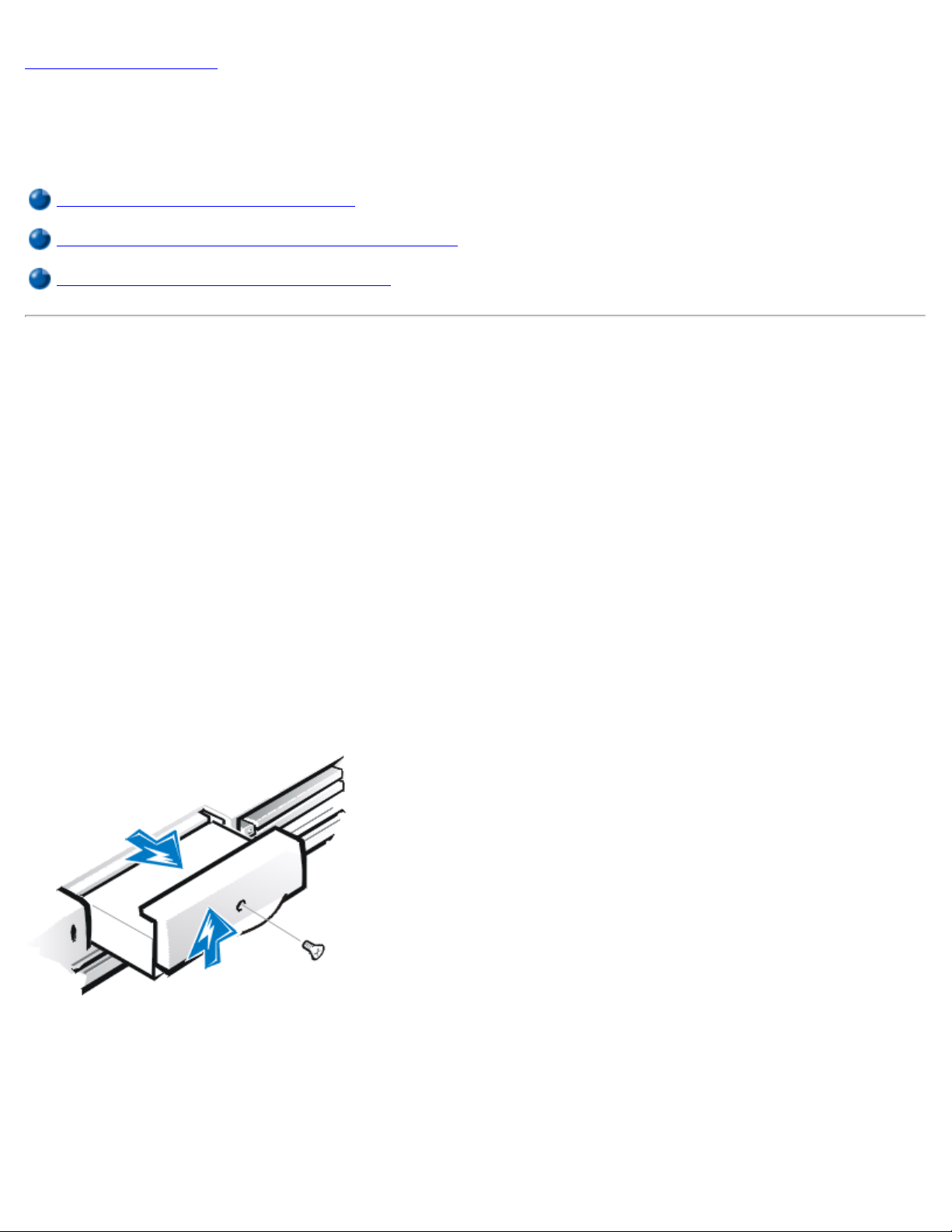
To install a primary hard-disk drive, perform the following steps:
1. Save any open files, turn off the computer, and remove any installed batteries.
2. Remove the hard-disk drive from the drive bay.
Close the display and turn the computer over. Using a small Phillips-head screwdriver, remove the
screw (see Figure 1) that holds the drive carrier in the drive bay. Save the screw for use later in this
procedure.
Figure 1. Removing a Hard-Disk Drive
3. Gently pull the drive carrier out of the drive bay.
When the hard-disk drive is not in the computer, protect the drive from exposure to static
electricity. See "Protecting Against Electrostatic Discharge" in your System Information Guide for
more information.
4. Remove the new hard-disk drive from its packaging.
Page 23

Save the original packaging to use when you store or ship the hard-disk drive.
5. Install the new hard-disk drive into the computer (it comes in a drive carrier).
NOTICE: If the drive carrier does not slide in easily, pull it out and try again. To avoid damage, do
not force the drive carrier into the bay.
6. Gently push the drive carrier into the drive bay until the carrier door is flush with the computer case.
7. Replace the screw you removed in step 2. Be careful not to overtighten the screw.
If you have installed a new hard-disk drive, follow the directions that came with the drive to partition and
logically format the drive and to create a suspend-to-disk (S2D) partition.
NOTICE: Hard-disk drives are extremely fragile and must be handled carefully to avoid damage.
Follow these guidelines:
The primary hard-disk drive is installed in a metal carrier to protect the drive and make
installation easier. When you remove and install hard-disk drives, handle the drive carrier, not
the drive itself.
Never press down on the top of the drive.
Do not drop the drive. Even a slight jar or bump can damage the drive heads and spinning
plates, thus rendering the drive inoperable.
CAUTION: The primary hard-disk drive may be hot to the touch under extreme environmental
conditions. If the drive is hot, allow it to cool before you replace it.
Preparing a New Primary Drive
Every primary hard-disk drive must be physically formatted, partitioned, and logically formatted before it can
be used to store data. Every primary hard-disk drive from Dell is physically formatted before it is sent to you.
Use the program(s) provided by your operating system to partition and logically format the hard-disk drive.
Preparing to Remove or Install Memory Modules
To prepare the computer for the removal or installation of memory modules, perform the following steps.
NOTES: If necessary, print these instructions for reference before proceeding.
NOTICE: Your portable computer does not support extended-data out (EDO) memory modules.
Only synchronous dynamic random-access memory (SDRAM) modules are supported for use in
Dell Latitude CPx H-Series/J-Series computers.
NOTICE: Do not install memory modules while the computer is in suspend, standby, or suspend-todisk mode.
NOTICE: Ground yourself by touching an unpainted metal surface of a connector on the back of the
Page 24
computer. While you work, periodically touch the connector to dissipate any static electricity that
might harm internal components.
1. Turn off the computer and any attached peripherals, and disconnect them from their electrical outlets to
reduce the potential for personal injury or shock.
2. If the computer is docked, undock it.
3. Disconnect the AC adapter and any attached peripherals, including telephone or telecommunication
lines, from the computer.
4. Remove the battery from the battery bay or the modular bay.
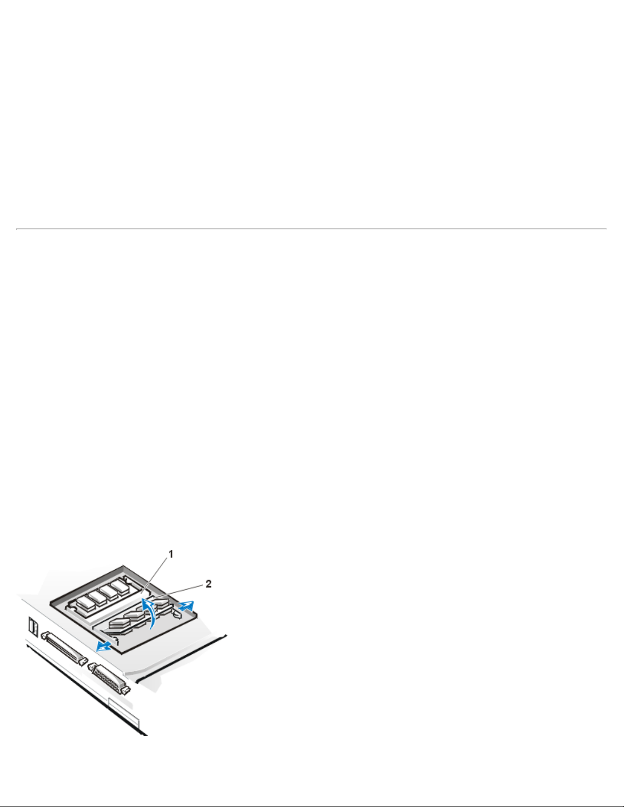
Removing or Installing Memory Modules
To remove or install memory modules, perform the following steps:
1. Close the display, and turn the computer upside down.
2. Remove the memory module cover.
Locate the small rectangular indentation at one end of the memory module cover. Place the tip of
your finger under the cover by the indentation and firmly lift it up. When the door pops up, lift it up
to remove it and expose the memory modules underneath it.
3. If you are replacing a memory module, remove the old one.
Carefully spread apart the inner metal tabs of the memory module socket just far enough for the
memory module to disengage from the socket (it should pop up slightly). Then lift the memory module
away from the socket (see Figure 2).
Figure 2. Removing a Memory Module
Page 25

1 DIMM A
memory:
2 DIMM B
4. Ground yourself and unpack the new memory module from the upgrade kit.
5. Install the new memory module into the appropriate slot.
NOTES: If you are installing a 192-MB memory module, be sure that it is inserted with the
double-stacked memory chips facing you. A 192-MB memory module inserted with the doublestacked memory chips facing down does not fit properly in the socket.
192-MB memory modules are designed for either the socket labeled DIMM A or the socket
labeled DIMM B. They are not interchangeable.
The socket labeled DIMM A should be populated before the socket labeled DIMM B. If you only
have one memory module, you should install it in the DIMM A socket. (See Figure 2
Memory modules are keyed, or designed to fit into their sockets in only one direction. The slots on
the system board are notched so that the memory module can be firmly seated only one way.
a. Align the memory module’s edge connector with the slot in the center of the memory
module socket.
.)
b. With the module at a 45-degree angle, press the memory module’s edge connector firmly
into the memory module socket.
c. Pivot the memory module down until it clicks into place.
If you do not hear a click as each end of the memory module snaps into the metal tabs, remove
the memory module and reinstall it.
NOTICE: After installation, if the memory module cover does not fit or is difficult to close, you may
have installed the memory module improperly into the wrong slots. Remove the memory modules
and reinstall them. Do not force the memory module cover to close because you may damage your
computer.
6. Replace the memory module cover as follows:
a. Set the memory module cover loosely over the opening, making sure that the tabs on the
bottom of the cover catch in the slots on either side of the opening.
b. Slide the cover into place and press down on it until you hear it click.
7. Reconnect your computer and peripherals to their electrical outlets and turn them on.
As the computer boots, it detects the presence of additional memory and automatically updates
the system configuration information.
8. In one of the following ways, verify that the System Memory option reflects the newly installed
Page 26

Click the Start button, point to Settings, click Control Panel, and double-click the System
icon. The amount of memory installed in the computer is displayed in the lower-right corner
of the General tab window.
In the System Setup program, the System Memory option appears in the lower-right corner
of pages 1, 2, and 4.
To run the System Setup program, press <Fn><F1> on the computer’s keyboard (or <Scroll
Lock><F1> on an external keyboard if the External Hot Key option is enabled).
If the total amount of memory shown is incorrect, the memory module(s) may not be installed
properly. Repeat preparatory steps
until the memory total is correct.
9. Run the System Memory test of the Dell Diagnostics to confirm that all installed memory modules are
operating correctly.
10. Use the Suspend-to-Disk utility to update the S2D partition on your hard-disk drive. The S2D partition
stores system data while the computer is in suspend-to-disk mode.
1 through 4 and removal and installation steps 1 through 8
Back to Contents Page
Page 27

Back to Contents Page
Troubleshooting Your Computer: Dell™ Latitude™ CPx H -Series/JSeries User's Guide
Dell Diagnostics
Error Messages and Flash Codes
Back to Contents Page
Page 28

Back to Contents Page
Technical Specifications: Dell™ Latitude™ CPx H-Series/J -Series
User's Guide
Processor Keyboard
Chip Set and Bus Battery
PC Cards AC Adapter
Memory Physical
Connectors Environmental (Computer)
Audio Touch Pad
Video Track Stick
14.1-Inch Display
Processor
Latitude CPx H-Series/J-Series Intel® Mobile Pentium® III microprocessor. For J-Series,
microprocessor includes Intel SpeedStep™ technology
Chip Set and Bus
System chip set Intel Mobile 440BX AGPset
Microprocessor data bus width 64 bits
DRAM bus width 64 bits
Address bus width 32 bits
Flash EPROM 4 Mb
AGP bus 66 MHz
PCI bus 33 MHz
PC Cards
CardBus controller Texas Instruments PCI 1225 CardBus controller
PC Card connectors two (supports type I and type II cards in any combination; type
Page 29

III cards can be used only in the lower connector; the lower
connector supports zoomed video cards on systems using the
Microsoft® Windows® 95 or Windows 98 operating system)
Cards supported 3.3-V and 5-V
PC Card connector size 68 pins
Data width (maximum):
PCMCIA 16 bits
CardBus 32 bits
Memory
Architecture SDRAM
Memory module sockets two
Memory module capacities and type 32-, 64-, 128-, 192-, and 256-MB
3.3-V SDRAM
1
modules
Standard RAM 32-MB memory module
Maximum RAM 512 MB
Memory clock speed 100 MHz
Memory access time CL2 or CL3 (Note: CL3 indicates a CAS latency of 3 clocks)
BIOS address F000:0000-F000:FFFF
Connectors
Serial (DTE) 16,550-compatible, 16-byte buffer connector
Parallel unidirectional, bidirectional, or ECP connector
Video connector
PS/2 mini-DIN connector
Infrared port compatible with both IrDA Standard 1.1
(Fast IR) and IrDA Standard 1.0 (Slow IR)
Audio microphone-in jack;
line-in/audio-in jack;
headphones/speakers jack
USB USB-compliant connector
Page 30

Docking connector for the C/Port Family Advanced Port
Replicator or C/Dock Family Expansion Station
S-Video 7-pin mini-DIN connector (an S-Video to composite video
Adapter is also included with the computer)
Audio
Audio type Sound Blaster (software emulation-capable)
Audio controller For the H-Series, ESS Maestro 2E; for the J-Series, ESS
Maestro 3I
Stereo conversion 16 bit (analog-to-digital and digital-to-analog)
Interfaces:
Internal PCI bus/AC97
External stereo line-in minijack;
microphone-in minijack;
headphones/speakers-out minijack
Speakers two 8-ohm speakers
Internal speaker amplifier 1 W channel into 8 ohms stereo
Controls volume can be controlled through key combinations, application
program menus, or the Speaker window in the Dell Control
Center (Windows 95 only)
Video
Video type 64-bit hardware-accelerated
Data bus 2X AGP
Video controller ATI Mobility M1
Video memory 8.0 MB
14.1-Inch Display
Type XGA, active-matrix color (TFT)
Dimensions (active area):
Height 214.3 mm (8.4 inches)
Page 31

Width 285.7 mm (11.3 inches)
Diagonal 357.1 mm (14.1 inches)
Maximum resolution/colors 1024 x 768; 24-bit color
Response time (typical) 20 ms rise (maximum)/50 ms fall (maximum)
Operating angle 0° (closed) to 180°
Viewing angles:
Horizontal ± 45°
Vertical +15°/–30°
Dot pitch 0.28 mm
Power consumption:
Panel (typical) 1.0 W
Backlight 3.4 W
Controls brightness can be controlled through a key combination
Keyboard
Number of keys 87 (U.S., Canada, Korea, Thailand, and locations that use
traditional Chinese);
88 (Europe);
90 (Japan)
Key travel 2.8 mm ± 0.4 mm
(0.11 inch ± 0.016 inch)
Key spacing 19.05 mm ± 0.3 mm (0.75 inch ± 0.012 inch)
Battery
Type lithium ion
Dimensions:
Height 21.5 mm (0.83 inch)
Depth 88.5 mm (3.48 inches)
Page 32

Width 139.0 mm (5.47 inches)
Weight 0.39 kg (0.87 lb)
Voltage 14.8 VDC
Capacity 53 WH
2
Charge time (approximate)
:
Computer on 2.5 hours
Computer off 1 hour
Life span (approximate)
2
500 discharge/charge cycles
Temperature range:
Charge 0° to 35°C (32° to 95°F)
Storage –40° to 65°C (–40° to 149°F)
AC Adapter
Input voltage 90 to 135 VAC and 164 to 264 VAC
Input current (maximum) 1.5 A
Input frequency 47 to 63 Hz
Output current 4.5 A (maximum at 4-second pulse);
3.51 A (continuous)
Rated output voltage 20.0 VDC
Height 27.94 mm (1.1 inches)
Width 58.42 mm (2.3 inches)
Depth 133.35 mm (5.25 inches)
Weight (with cables) 0.4 kg (0.9 lb)
Temperature range:
Operating 0° to 40°C (32° to 104°F)
Storage –40° to 65°C (–40° to 149°F)
Page 33

Physical
Height 45.0 mm (1.77 inches)
Width 319.0 mm (12.55 inches)
Depth 252.5 mm (9.94 inches)
Weight
3
with 14.1-inch display 2.73 kg (6.02 lb) with travel module installed in modular bay
2.93 kg (6.46 lb) with diskette drive installed in modular bay
3.06 kg (6.74 lb) with CD-ROM drive installed in modular bay
Environmental (Computer)
Temperature:
Operating 0° to 35°C (32° to 95°F)
Storage –40° to 65°C (–40° to 149°F)
Relative humidity (maximum):
Operating 10% to 90% (noncondensing)
Storage 5% to 95% (noncondensing)
Maximum vibration:
Operating 0.9 GRMS using a random-vibration spectrum that simulates
user environment
Storage 1.3 GRMS using a random-vibration spectrum that simulates
air/truck shipment
Maximum shock
Operating 152.4 cm/sec (60.0 inches/sec)
Storage 203.2 cm/sec (80 inches/sec)
Altitude (maximum):
Operating –15.2 m to 3048 m (–50 to 10,000 ft)
4
:
(equal to a half-sine pulse width of 2 ms)
(equal to a half-sine pulse width of 2 ms)
Storage –15.2 m to 10,668 m (–50 to 35,000 ft)
Page 34

Touch Pad
1
Interface PS/2-compatible
X/Y position resolution (graphics table
mode)
Size:
Thickness 2.8 mm (0.11 inch) at highest component
Width (sensor-active area) 55mm (2.17 inch)
Height 39-mm (1.54-inch) rectangle
Weight 9.02 g (0.29 oz)
Power:
Supply voltage 5 V ± .5 VDC
Supply current 25 mA (maximum operating for track stick and touch pad
240 cpi
combined)
ESD In accordance with IEC-801-2
Track Stick
Interface PS/2-compatible
X/Y position resolution 250 counts/sec.@100gf
Size: Protrudes .5 mm higher than surrounding keycaps
Power:
Supply voltage 5 V ± .5 VDC
Supply current 25 mA (maximum operating for track stick and touch pad
combined)
ESD In accordance with IEC-801-2
NOTES:
Page 35

The Dell Latitude CPx H-Series/J-Series does not support some memory modules from older models of
Dell portable computers, such as the Latitude CP, XP, XPi CD, or LM. The H-Series only supports
SDRAM modules and does not support EDO memory modules.
2
Battery performance features such as charge time and life span can vary according to the conditions
under which the computer and battery are used.
3
Weights are shown with a hard-disk drive, a battery in the battery bay, and a travel module, diskette
drive, or a CD-ROM drive in the modular bay. Your computer might weigh more or less, depending on its
configuration.
4
Measured with the hard-disk drive in head-parked position.
Back to Contents Page
Page 36

Back to Contents Page
Getting Help: Dell™ Latitude™ CPx H -Series/J-Series User's Guide
Help Overview
Contacting Dell
Back to Contents Page
Page 37

Back to Contents Page
Modular Bay: Dell™ Latitude™ CPx H-Series/J -Series User's Guide
Using the Modular Bay
Installing Devices in the Modular Bay With Softex Docking Services or Softex BayManager Software
Installing Devices in the Modular Bay Without Softex Docking Services or Softex BayManager Software
Using the Modular Bay
Your computer comes with a diskette drive installed in the modular bay. You can also install a battery, a CDROM drive, a CD-RW drive, a DVD-ROM drive, a SuperDisk LS-120 drive module, or second hard-disk drive
in the modular bay. To make the computer as light as possible, use the travel module in the modular bay in
place of any of the available drives.
NOTICE: When the drives are not inside the computer, they are fragile and must be handled
carefully to avoid damage. Do not press down on the drives or place heavy objects on top of them.
Place the drives in a travel case to keep them free of dust and liquids. Store the drives in a safe
place.
If your system is running Microsoft® Windows NT® with Softex Docking Services installed or if your system
is running Windows® 95 or Windows 98 with Softex BayManager installed, see "Installing Devices in the
Modular Bay With Softex Docking Services or Softex BayManager Software."
If your system does not have Softex Docking Services or Softex BayManager, see "Installing Devices in the
Modular Bay Without Softex Docking Services or Softex BayManager Software."
If you are removing a device from the modular bay and installing a battery, see "Batteries
If your system is running Windows 2000, device swapping in the modular bay is supported by the operating
system. Although you can physically remove and install devices as described in the following subsections,
refer to the information on unplugging or ejecting hardware in your Windows 2000 documentation instead of
following the Softex- or System Setup-related steps in the following subsections.
NOTE: A new hard-disk drive must be formatted before you can use it. For instructions, see the
documentation that came with the drive.
."
Installing Devices in the Modular Bay With Softex Docking Services or BayManager
Software
Your computer may be using Windows 95 or Windows 98 with Softex BayManager software or Windows NT
with Softex Docking Services software. This software allows you to hot-swap devices such as diskette
drives, hard-disk drives, SuperDisk LS-120 drives, CD-ROM drives, CD-RW drives, and DVD-ROM drives
to and from your computer’s modular bay and the C/Dock Family Expansion Station’s media bay. Hotswapping capability allows you to remove and replace a device while the computer is on. You do not have to
Page 38

shut down or restart the computer for the device to be recognized.
To install a device in the modular bay, perform the following steps:
1. Verify that the Diskette Reconfig
2. Verify that the Display Close option in the System Setup program is set to Active.
3. Save your work and close all open files and application programs.
4. If the computer is docked, undock it.
5. Double-click the Docking Services or BayManager icon in the Windows system tray on the task bar.
The Softex BayManager window appears for Windows 95 or Windows 98, and the Docking Services
window appears for Windows NT.
6. Click the Remove/Swap button.
7. If the modular bay contains a device, remove the device as follows:
a. Close the computer display and turn the computer over.
b. Slide the modular bay latch toward the Unlock icon.
option in the System Setup program is set to Any Time.
Keep holding the modular bay latch with one hand while pulling the device out of the bay with the
other hand.
c. After you remove the device, release the modular bay latch.
8. Slide the new device firmly into the modular bay.
You should hear a click when the device is fully seated.
NOTE: Softex BayManager and Softex Docking Services do not report a second battery installed
in the modular bay on the Storage Devices tab.
9. Click OK. Then click OK again to close the Softex window.
For the latest information on Softex Docking Services, see the Softex user’s guides at
http://www.dell.com/. Click Small Business Center or Medium & Large Business. Click Notebooks;
then, if applicable, click Choose Latitude. Look for Softex Utilities Installation Guide on the left of the
screen.
If you are removing a device from the modular bay and installing a battery, see "Batteries
."
Installing Devices in the Modular Bay Without Softex Docking Services or Softex
BayManager Software
To install a device in the modular bay, perform the following steps:
1. Verify that the Diskette Reconfig
option in the System Setup program is set to Any Time.
Page 39

Save your work and close all open files and application programs.
3. Turn your computer off.
4. If the computer is docked, undock it.
5. If the modular bay contains a device, remove the device as follows:
a. Close the computer display and turn the computer over.
b. Slide the modular bay latch toward the Unlock icon.
Keep holding the modular bay latch with one hand while pulling the device out of the bay with the
other hand.
c. After you remove the device, release the modular bay latch.
Slide the new device firmly into the modular bay.
You should hear a click when the device is fully seated.
7. Dock the computer if necessary.
8. Turn on the computer.
Back to Contents Page
Page 40

Back to Contents Page
Using the System Setup Program: Dell™ Latitude™ CPx HSeries/J -Series User's Guide
Overview
Entering the System Setup Program
Using the System Setup Program
Overview
Each time you turn on your computer, it compares the installed hardware with the system configuration
information stored in nonvolatile random-access memory (NVRAM). If the system detects a discrepancy, it
generates an error message for each incorrect configuration setting.
Power Management Compliance (APM Versus ACPI)
The system configuration process differs depending on the type of power management scheme used by the
operating system. Microsoft® Windows® 95 and Windows NT use Advanced Power Management (APM).
Windows 2000 uses Advanced Configuration and Power Management (ACPI). Windows 98 can be either
APM- or ACPI-compliant, depending on the version you are using. If you have Windows 98, you can
determine which power scheme you have by accessing the System devices list in the Device Manager.
For Windows 98 with APM, click Start—> Settings—> Control Panel—> System—> Device Manager—>
System devices.
For Windows 98 with ACPI, click Start—> Settings—> Control Panel—> System—> Hardware—>
Device Manager—> System devices.
Either APM or ACPI options will appear at the top of the System devices list.
To adjust the configuration settings for APM operating systems, such as Microsoft Windows 95,
Windows 98 with APM, or Windows NT®, you can use the System Setup program.
ACPI operating systems, such as Windows 2000 and Windows 98 with ACPI, automatically configure
most of the setup options available in the System Setup program. In such cases, the operating system
overrides system setup options entered through the System Setup program. One exception is the
External Hot Key option, which you can disable or enable only through the System Setup program.
For more information on configuring features for these operating systems, see your Microsoft Windows
Help.
NOTE: For ACPI operating systems, the System Setup program is accessible only during the
system boot routine.
You can use the System Setup program as follows:
Page 41

To set or change user-selectable features — for example, your password or power management
features
To verify information about your computer's current configuration, such as the amount of system
memory
For some setup options, you must reboot the computer before any changes take effect. Changes for other
options take effect immediately.
NOTE: If you change an option that is activated by rebooting, the System Setup program displays the
setting you selected rather than the setting currently in effect. You must reboot for the new setting to
take effect.
After you set up your computer, run the System Setup program to familiarize yourself with your system
configuration information and optional settings. Dell recommends that you write down the information for
future reference.
NOTE: If the computer uses the Microsoft Windows 95 operating system, you can also use the Dell
Control Center to view and change the system configuration. Access the Dell Control Center from the
Dell Accessories folder.
For more information, see "
System Setup Options."
Entering the System Setup Program
Enter and use the System Setup program as follows:
For APM operating systems, such as Windows 95, Windows 98 with APM, and Windows NT, press
<Fn><F1> at any time on the keyboard (or <Scroll Lock><F1> on an external keyboard if the External Hot
Key option is enabled). If you press <Fn><F3> (or <Scroll Lock><F3> on an external keyboard if the
External Hot Key option is enabled), the System Setup program opens directly to the Battery Status
screen.
For ACPI operating systems, such as Windows 2000 and Windows 98 with ACPI, you must enter System
Setup before the operating system loads. Enter System Setup by pressing <F2> when the F2 message
appears during the system boot routine.
Press <Esc> to exit the System Setup program. If you change the setting of an option that requires rebooting
to take effect, exit the operating system before rebooting. (The Help text in the upper-right corner of System
Setup screens 1, 2, and 4 tells you if the computer must be rebooted.)
NOTE: If the System Setup program is running when the computer enters suspend mode, the
computer exits the System Setup program and then activates suspend mode.
For more information, see "System Setup Options."
Using the System Setup Program
Page 42

The System Setup screens display the current setup and configuration information and optional settings for
your computer. Information on the screens is organized in five boxed areas:
Title
The box at the top of all screens lists the page number, system name, and version number of the basic
input/output system (BIOS).
Options
The box on the left half of screens 1, 2, and 4 lists options that define the installed hardware in your
computer and the power conservation and security features for your computer.
Fields next to the options contain settings or values. You can change those values that appear bright
on the screen. Options or values that you cannot change (because they are determined or calculated
by the computer) appear less bright.
Help
The box on the upper-right half of screens 1, 2, and 4 displays help information for the option with a
currently highlighted field.
Computer data
The box in the lower-right corner of screens 1, 2, and 4 displays information about your computer.
Key functions
The line of boxes across the bottom of all screens lists keys and their functions within the System
Setup program.
For more information, see "
Back to Contents Page
System Setup Options."
Page 43

Back to Contents Page
Dell™ Diagnostics: Dell Latitude™ CPx H -Series/J-Series User's Guide
Overview Dell Diagnostics Main Screen Overview
Features of the Dell Diagnostics Confirming the System Configuration Information
When to Use the Dell Diagnostics How to Use Dell Diagnostics
Starting the Dell Diagnostics
Overview
Unlike many diagnostic programs, the Dell Diagnostics helps you check your computer's hardware without any
additional equipment and without destroying any data. By using the diagnostics, you can have confidence in your
computer's operation. And if you find a problem you cannot solve by yourself, the diagnostic tests can provide you
with important information you will need when talking to Dell's service and support personnel.
NOTICE: Use the Dell Diagnostics to test only your Dell computer. Using this program with other computers
may cause incorrect computer responses or result in error messages.
Features of the Dell Diagnostics
The Dell Diagnostics provides a series of menus and options from which you choose particular test groups or
subtests. You can also control the sequence in which the tests are run. The diagnostic test groups or subtests also
have these helpful features:
Options that let you run tests individually or collectively
An option that allows you to choose the number of times a test group or subtest is repeated
The ability to display or print out test results, or to save them in a file
Options to temporarily suspend testing if an error is detected, or to terminate testing when an adjustable error
limit is reached
A menu category called Devices that briefly describes each test and its parameters
A menu category called Config that describes the configuration of the devices in the selected device group
Status messages that inform you whether test groups or subtests were completed successfully
Error messages that appear if any problems are detected
When to Use the Dell Diagnostics
Whenever a major component or device in your computer does not function properly, you may have a component
failure. As long as the microprocessor and the input and output components of your computer (the display, keyboard,
and diskette drive) are working, you can use the Dell Diagnostics. If you are experienced with computers and know
what component(s) you need to test, simply select the appropriate diagnostic test group(s) or subtest(s). If you are
unsure about how to begin diagnosing a problem, read the rest of this section.
Page 44

Starting the Dell Diagnostics
Perform the following steps to start the diagnostics:
1. Turn off the computer.
2. Undock the computer if you have it docked.
3. Turn on the computer.
4. Press <F2> at the Dell BIOS splash screen to access the System Setup menu.
5. Select the following boot sequence:
Boot First Device: Diskette Drive
Boot Second Device: CDROM / DVDROM Drive
Boot Third Device: Internal HDD
6. Insert the Dell System Software CD into the CD-ROM drive.
7. Turn the computer off.
8. Turn the computer on. The system restarts and automatically begins to run the Dell Diagnostics.
9. When you have completed running diagnostics, remove the Dell System Software CD from the CD-ROM drive.
To change the boot sequence, repeat steps 1 through 5, customizing the boot sequence to fit your needs. Then
restart your system.
NOTE: Before you read the rest of this subsection, you may want to start the Dell Diagnostics so that you can
see it on your display.
When you start the diagnostics, the Dell logo screen appears, followed by a message telling you that the diagnostics
is loading.
After the diagnostics loads, the Diagnostics Menu appears (see Figure 1
diagnostic tests or to exit to the MS-DOS prompt.
For a quick check of your computer, select the Quickly Test All Devices option. This option runs only the subtests
that do not require user interaction and that do not take a long time to run. Dell recommends that you choose this
option first to increase the odds of tracing the source of the problem quickly. For a thorough check of your computer,
select the Fully Test All Devices option. To check a particular area of your computer, select the Select Devices to
Test option.
). The menu allows you to run all or specific
To select an option from this menu, highlight the option and press <Enter>, or press the key that corresponds to the
highlighted letter in the option you choose.
Figure 1. Diagnostics Menu
Page 45

Dell Diagnostics Main Screen Overview
When you select Select Devices to Test from the Diagnostics Menu, the main screen of the diagnostics appears
(see Figure 2
and allows you to select categories from a menu. From this screen, you can enter two other types of screens.
Information on the main screen of the diagnostics is presented in the following five areas:
Two lines at the top of the screen identify the version number of the Dell Diagnostics.
On the left side of the screen, the Device Groups area lists the diagnostic test groups in the order they will run
if you select All from the Run tests menu category. Press the up- or down-arrow key to highlight a test device
group.
On the right side of the screen, the Devices for Highlighted Group area lists the computer's currently
detected hardware and some of the relevant settings.
The lower-right side of the screen displays information about your integrated drive electronics (IDE) hard-disk
and CD-ROM drive(s).
Two lines at the bottom of the screen make up the menu area. The first line lists the categories you can select;
press the left- or right-arrow key to highlight a menu category. The second line gives information about the
category currently highlighted.
). The main screen lists the diagnostic test device groups, lists the devices of the selected device group,
NOTE: The options displayed on your screen should reflect the hardware configuration of your computer.
Figure 2. Dell Diagnostics Main Screen
Page 46

Confirming the System Configuration Information
When you boot your computer from your diagnostics diskette, the diagnostics checks your system configuration
information and displays it in the Device Groups area on the main screen.
The following sources supply this configuration information for the diagnostics:
The system configuration information settings (stored in nonvolatile random-access memory [NVRAM]) that you
selected while using the System Setup program
Identification tests of the microprocessor, the video controller, the keyboard controller, and other key
components
Basic input/output system (BIOS) configuration information temporarily saved in RAM
Do not be concerned if the Device Groups area does not list the names of all the components or devices you know
are part of your computer. For example, you may not see a printer listed, although you know one is attached to your
computer. Instead, the printer is listed as a parallel port. The computer recognizes the parallel port as LPT1, which is
an address that tells the computer where to send outgoing information and where to look for incoming information.
Because your printer is a parallel communications device, the computer recognizes the printer by its LPT1 address
and identifies it as a parallel port. You can test your printer connection in the Parallel Ports tests.
How to Use Dell Diagnostics
Six comprehensive, menu-driven, online Help categories provide instructions on how to use the program and explain
Page 47

each menu item, test group, subtest, and test and error result. To enter the Help menu, perform the following steps:
Back to Contents Page
1. Highlight Select Devices to Test in the Diagnostics Menu.
2. Press <Enter>.
3. Press <h>.
The six Help menu categories are Menu
provides detailed descriptions of the devices that you are testing. The Help categories are explained below.
Menu Category
The Menu Help category provides descriptions of the main menu screen area, the Device Groups, and the different
diagnostic menus and commands and instructions on how to use them.
Keys Category
The Keys Help category explains the functions of the all of the keystrokes that can be used in Dell Diagnostics.
Device Group Category
The Device Group Help category describes the test group that is presently highlighted in the Device Groups list on
the main menu screen. It also provides reasoning for using some tests.
Device Category
The Device Help category is the educational section of online Help. It describes the function and purpose of the
highlighted device in the Device Groups. For example, the following information appears when you select the
Device Help category for Diskette in the Device Groups list:
, Keys, Device Group, Device, Test, and Versions. The online Help also
Diskette drive A:
The diskette disk drive device reads and writes data to and from diskettes. Diskettes
are flexible recording media, sometimes contained in hard shells. Diskette recording
capacities are small and access times are slow relative to hard disk drives, but they
provide a convenient means of storing and transferring data.
Test Category
The Test Help category provides a thorough explanation of the test procedure of each presently highlighted test
group subtest. An example of the Diskette subtest Diskette Drive Seek Test is as follows:
Diskette drive A: - Diskette Drive Seek Test
This test verifies the drive's ability to position its read/write heads. The test
operates in two passes: first, seeking from the beginning to ending cylinders
inclusively, and second, seeking alternately from the beginning to ending cylinders
with convergence towards the middle.
Versions Category
The Versions Help category lists the version numbers of the subtests that are used by the Dell Diagnostics.
Page 48

Page 49

Back to Contents Page
AC Adapter: Dell™ Latitude™ CPx H-Series/J -Series User's Guide
Using the AC Adapter
Connecting the AC Adapter
Turning the Computer On
Using the AC Adapter
The AC adapter converts AC power to the DC power required by the computer. The AC adapter kit includes
two cables: the AC adapter cable and an AC power cable.
You can connect the AC adapter with your computer either turned on or off.
The AC adapter works with electrical outlets worldwide. However, power connectors vary among countries.
Before you use AC power in a foreign country, you may need to obtain a new power cable adapter designed
for use in that country.
If the computer is docked to one of Dell's C/Port Family Advanced Port Replicators (APR) or C/Dock Family
Expansion Stations, you can run the computer on AC power by connecting the AC adapter to the C/Port APR
or C/Dock Expansion Station.
NOTE: If you are running your computer on AC power with a battery installed, the AC adapter charges
the battery (if needed) and then maintains the battery's charge.
NOTICE: To avoid overheating, the AC adapter should be in a ventilated area, such as on a desktop
or on the floor, when used to power the computer or charge the battery. Do not use the AC adapter
in a poorly ventilated environment, such as inside a carrying case.
Connecting the AC Adapter
To connect the AC adapter, perform the following steps:
1. Connect the AC adapter power cable to the AC adapter (See Figure 1
2. Plug the AC adapter power cable into an electrical outlet.
3. Plug the AC adapter cable into the AC adapter connector on the computer.
).
Figure 1. Connecting the AC Adapter
Page 50

1 AC adapter power cable
2 AC adapter
3 AC adapter cable
Turning the Computer On
To turn on the computer, press the power button. (See Figure 1 in "Introduction.")
NOTE: If your computer's operating system is "locked up"— that is, it does not respond to commands
— press and hold down the power button for at least five seconds to shut it off.
Back to Contents Page
Page 51

Back to Contents Page
PC Cards: Dell™ Latitude™ CPx H-Series/J -Series User's Guide
About PC Cards Removing PC Cards
Installing PC Cards Configuring PC Cards
About PC Cards
The computer has a slot into which you can install up to two PC Cards if the PC Cards comply with Release
2.01 of the Personal Computer Memory Card International Association (PCMCIA) standard and Release 4.2
of the Japanese Electronic Industry Development Association (JEIDA) standard.
The computer supports type I, type II, and type III PC Cards (including memory cards) and advanced
technology attachment (ATA) cards that emulate integrated drive electronics (IDE) hard-disk drives. Also
supported are input/output (I/O) cards such as modems, local area network (LAN) cards, wireless LAN cards,
and small computer system interface (SCSI) cards.
If you are using the Microsoft® Windows® 95, Windows 98, or Windows 2000 operating system, you can use
a zoomed video (ZV) PC Card only in the lower PC Card connector. (The Microsoft Windows NT® 4.0
operating system does not support ZV.)
NOTES: A PC Card is not a boot device. The "type" of a card refers to its thickness, not its
functionality.
Your computer recognizes most I/O cards and automatically loads the device driver associated with
that card.
NOTICE: Take extra precautions if you use extended PC Cards in your computer. Extended cards
are longer versions of standard PC Cards. They fit into, and operate correctly with, your computer.
However, they extend beyond the edge of the computer when installed. If something strikes the
exposed end of an installed card, your system board can be damaged. Because of space
considerations, you may have trouble using two PC Cards in your computer if one of them is an
extended card. It may be easier to use an extended card if you install it in the upper PC Card
connector. Always remove an extended PC Card before you pack the computer in its carrying case.
Installing PC Cards
You can use the following PC Card combinations in the PC Card slots:
A single type I or type II card (using either the upper or lower PC Card connector)
A single type III card (using the lower PC Card connector only)
One type I card and one type II card (using either connector)
Two type I cards or two type II cards
Page 52

Note: Use a ZV PC Card in the lower connector only.
3. Gently remove the card.
PC Cards are generally marked with a symbol, such as a triangle or an arrow, to indicate which end should
be inserted into the slot. The cards are keyed to prevent incorrect insertion. If card orientation is not clear,
see the documentation that came with the card.
You do not need to turn off your computer or exit suspend or standby mode before you install a PC Card. To
install a PC Card (see Figure 1
1. If necessary, remove the blank from the PC Card connector you intend to use by pressing the eject
button and pulling the blank out.
2. Hold the card with its orientation symbol pointing into the slot and the top side of the card facing up.
3. Insert the card into the slot, and press in firmly until the card is completely seated in the internal PC
Card connector.
4. If you encounter too much resistance when inserting it, do not force the card. Check the card's
orientation and try again.
Figure 1. Installing a PC Card
), perform the following steps:
PC Card Blanks
Save the blank to use whenever you do not have a PC Card installed. The blank protects the PC Card
connector from dust and other particles.
Removing PC Cards
NOTICE: If you are using Windows 95, Windows 98, or Windows 2000, use the PC Card
configuration utility on the taskbar to select and stop a card before you remove it. If you do not
remove the card in the configuration utility, you could lose data from open application programs.
To remove a PC Card (see Figure 2
1. Stop the PC Card using the PC Card configurations utility on the taskbar.
2. Press the PC Card eject button.
The PC Card or blank protrudes from the slot slightly. It does not come out all the way.
), perform the following steps:
Page 53

Figure 2. Removing a PC Card
To protect the PC Card connectors, install a blank if you are not going to use the connector.
Configuring PC Cards
The PC Card configuration utility performs the following functions:
Notifies you whenever a PC Card is inserted and tells you how the card is configured
Automatically loads the proper device driver if it is available on the hard-disk drive
If drivers are not available on the hard-disk drive, prompts you to install them using the device driver
diskette that came with the card
The operating system automatically detects a PC Card and opens the Add New Hardware menu from the
Control Panel. For more information, see the PC Card operating system documentation.
Back to Contents Page
Page 54

Back to Contents Page
Batteries: Dell™ Latitude™ CPx H -Series/J-Series User's Guide
About the Batteries Second Low-Battery Warning
Charging a Hot Battery Charging the Battery
Battery Usage Detecting Battery Problems
Installing a Battery in the Battery Bay Battery Disposal
Installing a Second Battery About Battery Power
Battery Charge Gauge Turning the Computer On
First Low-Battery Warning
About the Batteries
Your computer’s lithium ion battery provides power when an electrical outlet is not available. A battery in the battery bay
is standard with the computer. Lithium ion batteries are longer lived than conventional batteries and do not require
replacement as often. To double battery life, install a second battery in the modular bay. Lithium ion batteries do not
have the "memory effect" that is exhibited by nickel-metal hydride (NiMH) and nickel-cadmium (NiCD) batteries. You do
not need to drain a lithium ion battery completely before recharging it. A lithium ion battery will not "forget" at which point
it is fully charged. NiMH and NiCD batteries may not charge fully if they are partially drained then recharged.
The lithium ion technology used in your computer’s battery is significantly less hazardous to the environment than the
lithium metal technology used in some other batteries (such as watch batteries). Spent batteries should not be placed
with common household waste products. Contact local authorities for the location of a chemical waste collection
program nearest you.
Keep the following information in mind when you are running your computer from the battery:
You can expect 2.5 to 5 hours of battery life with a single fully charged battery and 6 to 10 hours of battery life with
two fully charged batteries. Actual performance varies, depending on which power management features are
enabled and which application programs are being used.
When two batteries are installed, the AC adapter first charges the battery in the battery bay.
The integrated charge gauge lets you check a battery’s charge before you insert it into the computer.
The battery’s self-test capability alerts you to battery conditions such as low charge.
There is no battery memory effect with lithium ion batteries—you can charge the battery whenever you like without
fear of reducing its charge capacity.
A battery has a life span of up to 500 full charges and 2000 partial charges, provided it is charged at normal room
temperature.
Charging a Hot Battery
If your battery is hot from being used in your computer or being in a hot environment, take note of the following
precautions:
Page 55

A hot battery will not charge when you connect the AC adapter to the computer. This safety feature is important
because charging a hot battery shortens the battery’s life span and may damage the battery and the computer.
The battery is too hot to start charging if the battery indicator flashes alternately green and amber. If this occurs,
disconnect the computer from its electrical outlet and allow it and the battery to return to room temperature.
Reconnect the computer to the electrical outlet and continue charging the battery.
If the computer is not allowed to return to room temperature, the battery stops charging before it reaches its full
capacity.
Battery Usage
The battery is partially charged when you receive it. Dell recommends that you charge your battery to full capacity
before using it to power the computer.
If you are powering the computer from a battery, try to conserve battery power. A number of factors affect battery
operating time:
Power conservation features that you use
Type of display and microprocessor your computer has
Use of the optical or storage drive modules
Number and type of PC Cards and other external devices you use
Kinds of application programs you run
Capacity of the memory modules you install (the higher the capacity, the more power used)
Use of the infrared port
When you activate suspend mode (known as standby
can run on battery power for approximately one week (if the battery was fully charged before activating suspend or
standby mode).
If you are going to store the computer, disconnect all peripheral devices and turn off the computer. Remove the battery
when you store your computer for an extended period of time. A battery will drain when not in use during prolonged
storage. After a long storage period, recharge the battery fully before you attempt to run your computer from battery
power.
in the Microsoft® Windows® 98 operating system), the computer
Installing a Battery in the Battery Bay
NOTICE: To avoid data loss, do not replace a battery while the computer is turned on unless the computer is
connected to an electrical outlet or a second battery is installed.
To install a battery in the battery bay, perform the following steps (see Figure 1).
NOTES: You can also install a battery in the modular bay.
If necessary, print these instructions for reference before proceeding.
Figure 1. Installing a Battery
Page 56

1. Save your work and close all open files and application programs.
2. If the computer is docked, undock it.
3. If the modular bay contains a battery, go to step 5.
4. If the only battery in the computer is in the battery bay and that is the battery you want to replace, connect the
computer to an electrical outlet or preserve your data in one of these ways:
Use suspend mode.
Place the computer in suspend mode by pressing <Fn><Esc> (or <Scroll Lock><Esc> on an external
keyboard if the External Hot Key option is enabled in the System Setup program). Then shut down the
computer.
Use suspend-to-disk mode.
Place the computer in suspend-to-disk mode by pressing <Fn><a> (or <Fn><q> on a French
keyboard). When the green power indicator turns off, continue.
5. Remove the battery from the battery bay.
a. Close the computer display and turn the computer over.
b. Slide the battery bay latch toward the Unlock icon. Hold the latch with one hand while pulling the
battery out of the bay with the other hand.
c. Release the latch after you remove the battery.
6. Slide the new battery firmly into the battery bay. You should hear a click when the battery is fully seated.
7. If you put the computer into suspend or suspend-to-disk mode, press the power button to resume normal
operation.
Installing a Second Battery
NOTICE: To avoid data loss, do not replace a battery while the computer is turned on unless the computer is
connected to an electrical outlet or a second battery is installed.
NOTE: The following procedure applies only if you are replacing a storage module that has been operating in the
modular bay. If you are installing a battery into an empty modular bay, you can hot-swap the battery (insert the
battery while the computer is on).
1. Save your work and close all open files and application programs.
2. If the computer is docked, undock it.
Page 57

3. If your system does not have Softex Docking Services or Softex BayManager, go to step 5.
4. If your system is running Microsoft Windows NT® with Softex Docking Services installed or if your system is
running Windows 95 or Windows 98 with Softex BayManager installed, perform the following steps.
a. Double-click the Docking Services or BayManager icon in the Windows system tray on the task bar.
The Softex BayManager window appears for Windows 95 or Windows 98. The Docking Services
window appears for Windows NT.
b. Click the Remove/Swap button.
5. If BayManager is not installed, preserve your data in one of these ways and then go to step 6:
Use the suspend mode.
Place the computer in suspend mode by pressing <Fn><Esc> (or <Scroll Lock><Esc> on an external
keyboard if the External Hot Key option is enabled in the System Setup program).
Use the suspend-to-disk mode.
Place the computer in suspend-to-disk mode by pressing <Fn><a> (or <Fn><q> on a French
keyboard). When the green power indicator turns off, continue.
6. Remove any device that may be installed in the modular bay (see Figure 2
a. Close the computer display and turn the computer over.
b. Slide the modular bay latch toward the Unlock icon to release the device in the bay. Hold the latch in
the unlock position while pulling the device out of the bay.
c. Release the latch after you remove the device.
Figure 2. Removing a Device from the Modular Bay
).
7. Slide the new battery firmly into the battery bay. You should hear a click when the battery is fully seated.
NOTE: Softex BayManager and Docking Services do not report a second battery installed in the modular
bay on the Storage Devices tab.
8. If your system is running Microsoft Windows NT with Softex Docking Services or Windows 95 or Windows 98 with
Softex BayManager, click OK. Then click OK to close the Softex window.
Page 58

9. If you put the computer into suspend or suspend-to-disk mode, press the power button to resume normal
operation.
Battery Charge Gauge
The battery charge gauge consists of five indicators. Each indicator represents 20 percent of full charge. If only one
indicator lights up, recharge the battery before using it.
To check the charge level, press the battery test button that is next to the indicators (see Figure 3
number of indicators lights up for a few seconds to indicate the amount of charge remaining in the battery. For example,
if three indicators light up, your battery has between 41 percent and 60 percent of its charge left.
Figure 3.Battery Charge Gauge
NOTES: An indicator that blinks rapidly when you check the battery’s charge level indicates a
temporary failure or a potentially recoverable failure like overheating. Allow the battery to cool for
several minutes before checking the charge level again.
). The appropriate
If the battery is experiencing a permanent failure, when you press the battery test button, you will see
no indicators. If you install such a battery into the computer, the amber battery indicator on the
computer flashes rapidly. To purchase a new battery, call Dell
site at http://www.dell.com. Dispose of the old battery properly.
Percentage of Charge
When you press the battery test button, the number of indicators that light up shows an estimate of the remaining
battery charge:
If one indicator lights up, the battery has 1 to 20 percent of its charge remaining.
If two indicators light up, the battery has 21 to 40 percent of its charge remaining.
If three indicators light up, the battery has 41 to 60 percent of its charge remaining.
If four indicators light up, the battery has 61 to 80 percent of its charge remaining.
If five indicators light up, the battery has 81 to 100 percent of its charge remaining.
or access the Dell World Wide Web
Page 59

First Low-Battery Warning
properly closing any open files.
The first low-battery warning—a blinking amber battery indicator—occurs when you have about 15 minutes of battery
life left under current conditions and the computer is not connected to an electrical outlet. Figure 4 shows the battery
indicator status lights.
Figure 4. Status Lights
1 Power indicator
2 Drive access indicator
3 Battery indicator
NOTICE: When you see a low-battery warning, save your work immediately. Then replace the battery or
connect your computer to an electrical outlet.
After the first low-battery warning, if no input/output (I/O) activity occurs within 75 seconds, the computer activates
suspend-to-disk mode. If the computer has no suspend-to-disk partition, the computer enters suspend mode. The
computer can preserve data for several hours in suspend mode.
If you have set the computer to enter suspend-to-disk mode after a certain amount of time with no I/O activity, the
computer enters suspend-to-disk mode before the final low-battery warning. Once suspend-to-disk mode is activated,
no further power is consumed.
NOTICE: Never turn off the computer while the drive access indicator is on. Doing so could cause data loss.
Instead, close all of your application programs before you turn off the computer.
Second Low-Battery Warning
The second low-battery warning—a steady amber battery indicator—occurs when you have about 5 minutes of battery
life left under current conditions and the computer is not connected to an electrical outlet.
After the second low-battery warning, if no further I/O activity occurs within 15 seconds, the computer activates
suspend-to-disk mode. If there is no suspend-to-disk partition, the computer enters suspend mode. The computer can
preserve data for several hours in suspend mode.
If the computer is already in suspend mode when a final low-battery warning occurs, the computer activates suspendto-disk mode immediately. If suspend-to-disk mode has been disabled, the computer reenters suspend mode.
NOTICE: To avoid losing data (and possibly corrupting data areas on your hard-disk drive), save your work
immediately after a second low-battery warning. Then connect your computer to an electrical outlet, or place
the computer in suspend mode. If the battery runs completely out of power, the computer shuts off without
Page 60

Charging the Battery
Each time you connect the computer to an electrical outlet or install a battery in a computer that is connected to an
electrical outlet, the computer checks the battery's charge. The AC adapter charges the battery (if needed) and then
maintains the battery's charge.
NOTE: For maximum battery performance, charge the battery only at normal room temperature.
If two batteries are installed in the computer, the AC adapter first charges the battery in the battery bay, then the battery
in the modular bay.
When installed in a computer connected to an electrical outlet, the battery immediately starts charging. The green power
indicator remains steady while the AC adapter charges the battery. The indicator starts blinking when the express
charge cycle is complete. While the indicator is blinking, the AC adapter provides a trickle charge to bring the battery to
full capacity. The indicator continues to blink until you remove the battery or disconnect the computer from its electrical
outlet.
NOTICE: If the battery indicator flashes alternately green and amber while the computer is connected to an
electrical outlet, disconnect the computer from the outlet and allow the computer and the battery to return to
room temperature. Then reconnect the computer to its electrical outlet and continue charging the battery. If
the computer is not allowed to return to room temperature, the battery stops charging before it reaches full
capacity.
If the computer is turned off and connected to an electrical outlet through the AC adapter, it takes the AC adapter about
1 hour to fully charge a battery that has been completely discharged. If the computer determines that the battery is near
full capacity, the AC adapter skips the express-charging process and starts trickle-charging the battery. If the computer
is on, it takes up to 2.5 hours to charge a fully discharged battery, depending on which devices you are using and which
programs you are running.
NOTE: You can leave the battery in the computer as long as you like. The battery's integrated circuitry prevents
the battery from overcharging.
Detecting Battery Problems
A battery problem may prevent the battery from being charged to its full potential and can lead to unpredictable
operation. To obtain a new battery, call Dell
Dell suggests you follow these precautions when using the battery:
To avoid installing a defective battery in your computer, first check the battery's charge, indicated by the battery
charge indicators on the battery itself, by pressing the battery test button (see Figure 3
NOTE: If the battery has a 0 (zero) percent charge, you cannot use the battery test button to check
the battery's capacity. The battery gauge indicator will not light if the battery is completely drained.
or access the Dell World Wide Web site at http://www.dell.com.
).
If, after you insert the battery in the computer, the computer's battery indicator status light (see Figure 4) flashes
alternately green and amber, the battery is too hot to charge. Turn off the computer, and let the battery and
computer cool to room temperature.
If, after you insert the battery in the computer, the computer's battery indicator status light (see Figure 4) flashes
amber for 4 seconds when you connect or disconnect the AC adapter or when you press the power button, you
Page 61

need to replace the battery.
If, after you insert the battery in the computer, the computer's battery indicator status light (see Figure 4) flashes
rapidly amber, the battery is defective and needs to be replaced.
Battery Disposal
When your battery no longer holds a charge, call your local waste disposal agency or environmental agency for advice
on disposing the computer’s lithium ion battery.
CAUTION: Do not puncture or incinerate the battery.
NOTES: The lithium ion technology used in your computer’s battery is significantly less hazardous to the
environment than the lithium metal technology used in some other batteries (such as watch batteries).
This computer is supplied with a lithium ion battery. Lithium ion batteries are longer lived than conventional
batteries and do not require replacement as often. Spent batteries should not be placed in common household
waste products. Contact local authorities for the location of a chemical waste collection program nearest you. To
purchase a new battery, call Dell
or access the Dell World Wide Web site at http://www.dell.com.
About Battery Power
You automatically conserve battery power each time you attach the computer to an electrical outlet. The battery is even
being recharged when you use AC power. The battery's life expectancy is largely determined by the number of charges
it receives, so use an electrical outlet to run the computer whenever possible.
You can customize power management by individually controlling the computer's power conservation features. These
features reduce power consumption by monitoring application programs and computer devices for inactivity and slowing
down or stopping some of the computer’s internal devices.
NOTES: When you use power conservation features, you often trade some of the performance of the computer
for increased battery operating time. For example, if you turn off the hard-disk drive, you may experience a delay
the next time the computer tries to access the hard-disk drive.
Other power conservation features, such as suspend mode, stop almost all system activity. They allow you to
maximize power conservation when your work is interrupted.
Experiment with power conservation features to achieve the optimum power conservation for your work environment.
Turning the Computer On
To turn on the computer, press the power button (See Introduction).
NOTE: If your computer's operating system is "locked up"— that is, it does not respond to commands— press
and hold down the power button for at least five seconds to shut it off.
Back to Contents Page
Page 62

Back to Contents Page
CD-ROM, DVD -ROM, and CD -RW Drives: Dell™ Latitude™ CPx H Series/J -Series User's Guide
Using the CD-ROM and DVD-ROM Drives
Caring for CDs,DVDs, and CD-RW Discs
Types of Supported Discs
Using the Drives
The DVD-ROM and CD-ROM drives are read-only devices that let you play most commercially available 8or 12-centimeter (cm) sound and video CDs on the computer. In addition to playing most CDs, the DVDROM drive can also play DVDs. CD-rewritable (CD-RW) drives can write to and play CD-RWs and can play
CDs. Dell installed the appropriate CD-ROM drive device drivers on your hard-disk drive.
Use the DVD-ROM, CD-ROM, or CD-RW drive in the computer’s modular bay or the modular bay in a
C/Port Family Advanced Port Replicator (APR) or a C/Dock Family Expansion Station. None of these drives
can be used externally without an APR or an Expansion Station. You must turn the computer off before
installing the drive in the modular bay. For detailed instructions on installing devices in the modular bay, see
"Using the Modular Bay
Figure 1. DVD-ROM, CD-ROM, or CD-RW Drive Installed in Computer
NOTICE: Protect the DVD-ROM and CD-ROM drives when they are not in the modular bay. Do not
squeeze the drive or place objects on top of it; doing so could damage the drive motor. Keep the
drive as clean as possible.
."
NOTICE: Always use compressed air to clean the lens in the drive. Never touch the lens.
NOTICE: If the CD or DVD is not seated correctly, the drive can be damaged.
To play a CD, press the eject button on the face of the CD-ROM or DVD-ROM drive or press <Fn><F10>.
When the tray slides out, place the CD into the tray label side up. Make sure that the CD is seated correctly
on the spindle by pressing down on the disc until it clicks in place. Then gently push in the tray.
To play a DVD, press the eject button on the face of the DVD-ROM drive or press <Fn><F10>. When the
Page 63

tray slides out, place the DVD into the tray label side up. Make sure that the DVD is seated correctly on the
spindle by pressing down on the disc until it clicks in place. Then gently push in the tray.
NOTICE: Do not use the drive while the computer is in motion. Doing so could interrupt the flow of
data between the disc and the hard-disk drive or diskette drive.
When the CD-ROM or DVD-ROM drive is in use, the drive access indicator blinks on the computer’s front
panel.
If you are using the Microsoft® Windows® 95 or Windows 98 operating system, disable the autoplay feature
while you use the CD-ROM or DVD-ROM drive. (The autoplay feature can interfere with the computer’s
power management functions.) If Dell installed the operating system, the autoplay feature has been disabled.
If you reinstall the operating system or if you installed it yourself, be sure to disable the autoplay feature if you
want to use the CD-ROM or DVD-ROM drive.
For instructions on changing the Auto Insert Notification option, see the operating system user’s guide.
Caring for CD, DVD, CD-RW Discs
When handling and using the discs, follow these precautions:
Never use a damaged or warped disc.
Always hold the disc by its edges. Do not touch the surface of the disc.
Use a clean, dry cloth to remove dust, smudges, or fingerprints from the surface of the disc. When
cleaning, wipe from the center of the disc to the edge.
Never use solvents, such as benzene, record cleaners, or antistatic sprays, to clean the disc.
Do not write on the surface of the disc.
Store disc in its containers, placing them in a cool, dry place. Extreme temperatures may damage
discs.
Do not bend or drop a disc.
Do not place objects on top of a disc.
Types of Supported Discs
Your computer's CD-ROM, DVD-ROM, and CD-RW drives are able to play the following types of disc
formats:
CD-ROM red-book audio discs (CD-DA)
CD-ROM yellow-book mode-1 and mode-2 data discs
CD-ROM XA (mode-2 form 1 and form 2; without Adaptive Differential Pulse Code modulation
Page 64

[ADPCM])
CD-I (mode-2 form 1 and form 2)
CD-I Ready
CD-Bridge
Photo CD, CD-recordable (CD-R) (single and multisession)
Video CD
CD-rewritable (CD-RW) (the 24x CD-ROM and DVD-ROM drives can read, but not write to, CD-RW
discs; only the CD-RWs can write to this type of disc)
DVD-5 (the DVD-ROM drive supports the DVD-5 format)
Back to Contents Page
Page 65

Back to Contents Page
DualPoint Integrated Pointing Device: Dell™ Latitude™ CPx H Series/J -Series User's Guide
Cursor Pointing Devices Customizing the DualPoint Integrated Pointing Device
Using the Touch Pad Changing the Track Stick Cap
Using the Track Stick
Cursor Pointing Devices
Your Dell portable computer is equipped with the unique Dell DualPoint integrated pointing device. The
DualPoint integrated pointing device supports two types of cursor pointing devices (see Figure 1
2) that perform traditional mouse functions: the touch pad and the track stick. You can choose to use the
touch pad only, the track stick only, or both at the same time.
Two sets of buttons located above and below the touch pad enable you to perform standard mouse functions
with you thumb without removing your hands from the keyboard. You can also take advantage of "buttonless" selection by simply clicking or double-clicking on either the touch pad or the track stick.
and Figure
DualPoint integrated pointing device software allows you to set the default for the type of cursor pointing
device you want to use, as well as sensitivity, motion, and drag and drop features of both the touch pad and
track stick.
NOTES: When enabled, the DualPoint integrated pointing device (whether touch pad only, track
stick only, or both) uses interrupt request (IRQ) 12. No other device can use IRQ12 while the
DualPoint integrated pointing device is enabled.
When you attach an external PS/2-mouse to the computer, the DualPoint integrated pointing
device is automatically disabled.
Using the Touch Pad
The Personal System/2 (PS/2) touch pad (see Figure 1) detects the position of your finger over a touchsensitive area to position the cursor within the display screen. The touch pad provides the computer full
mouse functionality. The touch pad’s two buttons, located directly below the touch pad, correspond to the left
and right buttons on a standard mouse.
Figure 1. PS/2 Touch Pad
Page 66

To best use the touch pad, use the following techniques:
To move the cursor, lightly slide your finger over the smooth sensor area.
To select an object, gently tap once on the surface of the touch pad or use your thumb to press the left
touch pad button. The touch pad buttons perform standard mouse functions.
To select and move (or drag) an object, position the cursor on the object and tap down-up-down on the
touch pad. On the second down motion, leave your finger on the touch pad and move the selected
object by sliding your finger across the surface.
To double-click an object, position the cursor on the object and then tap the touch pad or the left touch
pad button twice.
Using the Track Stick
The track stick (see Figure 2) detects the pressure and direction that you move your finger when touching
the track stick cap located near the center of the keyboard. The two buttons located between the touch pad
and the space bar on the keyboard correspond to the left and right buttons on a standard mouse.
Figure 2. Track Stick
To best use the track stick, use the following techniques:
To move the cursor, apply pressure to the track stick with your right or left index finger. Press up or
down to move the cursor to the top or bottom of the display screen. Press left or right to move the
cursor to the left or right of the display screen.
Page 67

To select an object, tap once on the track stick or use your thumb to press the left track stick
button. The track stick buttons perform standard mouse functions.
To select and move (or drag) an object, position the cursor on the object. Then press and hold the left
track stick button. Leave your thumb on the button and move the selected object by pressing the track
stick in the desired direction.
To double-click an object, position the cursor on the object and then tap the left track stick button twice
or tap the track stick itself twice. The track stick functions much like the touch pad in that it allows you
to use buttons for mouse functions or the pointing device itself.
Customizing the DualPoint Integrated Pointing Device
The DualPoint integrated pointing device software allows you to set the default for the type of cursor pointing
device you want to use, as well as sensitivity, motion, and drag and drop features of both the touch pad and
track stick.To customize the DualPoint integrated pointing device, perform the following steps:
1. Click the Start button, point to Settings, and click Control Panel.
2. Double-click the Mouse icon to open the Mouse Properties window and click the Touch tab.
3. Select the settings that work best for you and click Apply.
4. Click OK to save the settings and close the window.
You can also click the touch pad icon on the taskbar and click Touch Pad Properties to open the Mouse
Properties control panel.
Changing the Track Stick Cap
Your computer came with four additional track stick caps in assorted colors. You may need to change the
track stick cap if it wears down from prolonged use.
To change the track stick cap, perform the following:
1. Pull the cap off the track stick (see Figure 3).
Figure 3. Removing the Track Stick Cap
Page 68

2. Align a new cap over the square track stick post and gently press the cap down onto the post.
3. Test the track stick to ensure that the cap is seated properly.
Back to Contents Page
Page 69

Back to Contents Page
Display: Dell™ Latitude™ CPx H -Series/J-Series User's Guide
Adjusting the Brightness Customizing Video Resolution
Expanded Video Mode Dual-Display Mode
Video Drivers and Video Resolution If You Have Display Problems
Adjusting the Brightness
To accommodate local lighting conditions or video output from the software you are using, you can use the
key combinations shown in Table 1
NOTE: When you run the computer on battery power, set your computer's brightness control to the
lowest setting that affords comfortable viewing. You can conserve up to 10 percent of battery power
by using the minimum brightness setting.
.
Table 1. Brightness Key Combinations and Their Functions
Key Combinations Function
<Fn> + down arrow Decreases brightness
<Fn> + up arrow Increases brightness
NOTES: You cannot change contrast on an active-matrix (thin film transistor [TFT]) display.
To use key combinations on an external keyboard, enable the External Hot Key option in the System
Setup program and use <Scroll Lock> instead of <Fn>.
Expanded Video Mode
When working in text mode, you can select the font used to display text. Press <Fn><F7> to toggle between
a regular serif font and a serif font with extra leading. Expanded video mode is useful if you are working in
800 x 600 resolution on a 14.1-inch XGA display.
NOTE: You may have trouble using the display fonts feature with MS-DOS® programs that use
downloaded fonts.
Page 70

Video Drivers and Video Resolution
The Dell-installed video drivers work with the operating system to let you customize the video resolution and
number of screen colors on your display.
NOTE: The Dell-installed video drivers are designed to offer the best performance on your computer.
Dell recommends that you use only these drivers with your factory-installed operating system.
Table 2 lists the combinations of resolutions and colors that the computer supports.
Table 2. Display Resolution, Colors, and Refresh Rates
Resolution Color Depth External CRT Display
Available Refresh
640 x 480 (VGA) 256 (8-bit) 60, 75, 85 Hz 60 Hz NTSC, 50 Hz PAL
640 x 480 (VGA) 65 k (16-bit) 60, 75, 85 Hz 60 Hz NTSC, 50 Hz PAL
640 x 480 (VGA) 16 M (24-bit) 60, 75, 85 Hz 60 Hz NTSC, 50 Hz PAL
640 x 480 (VGA) 4.2 B (32-bit) 60, 75, 85 Hz 60 Hz NTSC, 50 Hz PAL
800 x 600 (SVGA) 256 (8-bit) 60, 75, 85 Hz 60 Hz NTSC, 50 Hz PAL
800 x 600 (SVGA) 65 k (16-bit) 60, 75, 85 Hz 60 Hz NTSC, 50 Hz PAL
800 x 600 (SVGA) 16 M (24-bit) 60, 75, 85 Hz 60 Hz NTSC, 50 Hz PAL
800 x 600 (SVGA) 4.2 B (32-bit) 60, 75, 85 Hz 60 Hz NTSC, 50 Hz PAL
Television as Secondary
Display
Available Refresh
1024 x 768 (XGA) 256 (8-bit) 60, 70, 75, 85 Hz 60 Hz NTSC, 50 Hz PAL
1024 x 768 (XGA) 65 k (16-bit) 60, 70, 75, 85 Hz 60 Hz NTSC, 50 Hz PAL
1024 x 768 (XGA) 16 M (24-bit) 60, 70, 75, 85 Hz 60 Hz NTSC, 50 Hz PAL
1024 x 768 (XGA) 4.2 B (32-bit) 60, 70, 75, 85 Hz 60 Hz NTSC, 50 Hz PAL
1280 x 1024 (SXGA)* 256 (8-bit) 60, 70, 75, 85 Hz 60 Hz NTSC, 50 Hz PAL
1280 x 1024 (SXGA)* 65 k (16-bit) 60, 70, 75, 85 Hz 60 Hz NTSC, 50 Hz PAL
1280 x 1024 (SXGA)* 16 M (24-bit) 60, 70, 75, 85 Hz 60 Hz NTSC, 50 Hz PAL
1280 x 1024 (SXGA)* 4.2 B (32-bit) 60, 70, 75, 85 Hz 60 Hz NTSC, 50 Hz PAL
Page 71

1600 x 1200 (UGA)* 256 (8-bit) 60 Hz, 85 Hz 60 Hz NTSC, 50 Hz PAL
1600 x 1200 (UGA)* 65 k (16-bit) 60 Hz, 85 Hz 60 Hz NTSC, 50 Hz PAL
1600 x 1200 (UGA)* 16 M (24-bit) 60 Hz, 85 Hz 60 Hz NTSC, 50 Hz PAL
1600 x 1200 (UGA)* 4.2 B (32-bit) 60 Hz, 85 Hz 60 Hz NTSC, 50 Hz PAL
*NOTE: Pan mode may be turned on for the 1280 x 1024 (SXGA), 1400 x 1050 (SXGA Plus), and 1600 x
1200 (UGA) computer displays. In pan mode the screen resolution is too high to be completely displayed on
the computer display. For example, the taskbar that usually appears at the bottom of the desktop may no
longer be visible. To view the rest of the screen, use the touch pad or track stick to pan up and down and left
and right.
NOTICE: Before adjusting the refresh rate on an external monitor, refer to the monitor's user's guide.
You can damage the monitor by using an unsupported refresh rate.
To display more colors, select a lower resolution. If you select a resolution and color combination that the
system does not support, the system automatically selects the next supported combination.
NOTE: Color depth is based on 256 colors for 8 bit, 65,536 colors for 16 bit, 16,842,752 colors for 24
bit, and 4,294,967,296 colors for 32 bit displays.
Table 3 lists the maximum color depth possible for various combinations of resolutions without DVD and 3D.
Table 3. Display Resolution and Color Depth Without DVD and 3D Running
Primary/Secondary 640 x 480 800 x 600 1024 x 768 1280 x 1024
640 x 480 (8 bit)
800 x 600 (8 bit)
1024 x 768 (8 bit)
1280 x 1024 (8 bit)
1600 x 1200 (8 bit)
text text t t t
640 x 480 (16 bit)
800 x 600 (16 bit)
1024 x 768 (16 bit)
Maximum Color Depth Possible (in bits)
32 32 32 32
32 32 32 32
32 32 32 32
32 32 32 32
32 32 32 32
32 32 32 32
32 32 32 32
32 32 32 32
1280 x 1024 (16 bit)
1600 x 1200 (16 bit)
t t t t t
640 x 480 (24 bit)
32 32 32 32
32 32 24 24
32 32 32 32
Page 72

800 x 600 (24 bit)
32 32 32 32
1024 x 768 (24 bit)
1280 x 1024 (24 bit)
1600 x 1200 (24 bit)
t t t t t
640 x 480 (32 bit)
800 x 600 (32 bit)
1024 x 768 (32 bit)
1280 x 1024 (32 bit)
1600 x 1200 (32 bit)
32 32 32 32
32 32 32 24
24 24 16 8
32 32 32 32
32 32 32 32
32 32 32 24
32 32 24 16
8 8 -- --
Customizing Video Resolution
1. Click the Start button, point to Settings, and then click Control Panel.
The Control Panel window appears.
2. Double-click the Display icon.
The Display Properties window appears.
3. Click the Settings tab, and then set the resolution by dragging the slider in the Screen Area box. In
the Colors box, choose the number of colors from the menu provided. For more information, see your
operating system documentation.
If you choose a resolution or color palette that is higher than the display supports, the settings adjust
automatically to the closest possible setting.
Dual-Display Mode
With the Microsoft® Windows® 98 operating system, you can use an external monitor as an extension of
your display. To set up your computer for dual-display mode, perform the following steps:
1. Connect the external monitor, TV, or projector.
2. Click the Start button, point to Settings, and then click Control Panel.
3. In the Control Panel window, double-click the Display icon.
4. In the Display Properties window, click the Settings tab.
5. Change the Colors option to 256 Color or True Color (24 bit).
Page 73

6. Change the Screen Area to the appropriate size for your display.
7. Click the Advanced... button.
8. When the RAGE MOBILITY -M1 Properties window appears, select the Displays tab.
9. Click the Monitor button.
The dual display option is activated.
10. Click Yes when prompted to restart your system.
11. When the system has restarted, reopen the Display icon in the Control Panel.
12. Click the Settings tab.
Two displays now appear in this window.
13. Click the display that is grayed out. When asked if you want to enable this display, click Yes, and
then click Apply.
NOTE: True Simul-mode (the ability to simultaneously display video of the same content and
resolution on both the computer display screen and the external display) is not supported if the
system is booted to MS-DOS®, using a full-screen MS-DOS session under a Microsoft Windows
operating system, or the ATI Mobility M1 video driver is not loaded. This limitation may also be noted
in operating systems other than Microsoft Windows.
If You Have Display Problems
If your computer is receiving power, but nothing appears on your display (such as light, text, or graphics) or
the display image does not appear as you would expect, try the following measures to resolve the problem:
1. If the display is blank, you may be in suspend or standby mode. Press the power button to resume from
suspend mode or standby mode. If the display is blank and the power light-emitting diode (LED) is on,
the display may have timed out. In this case, press any key on the keyboard or move the mouse to
resume normal operation.
2. If the low-battery light is blinking, connect the AC adapter to the computer or replace the battery.
3. Adjust the brightness.
4. If your computer is attached to an external monitor, press <Fn><F8> to switch the video image to the
display.
Back to Contents Page
Page 74

Back to Contents Page
Securing Your Computer: Dell™ Latitude™ CPx H -Series/J-Series
User's Guide
About Passwords Using a Hard-Disk Drive Password
Using a Primary Password Physically Securing the Computer and the Hard-Disk Drive
Using an Administrator Password Asset Tag Utility
About Passwords
A primary password prevents unauthorized access to the computer at start-up. An administrator password
can be used in place of the primary password. A hard-disk drive password helps prevent the unauthorized
access of data on the hard-disk drive, even when the device is placed into another computer.
NOTES: All three passwords are disabled when you receive your computer. You need to assign those
passwords if you require password security for your computer. Some companies may assign any or
all of these passwords before distributing the computer.
If you are using the Microsoft® Windows NT® operating system, use the System Setup program to
assign all passwords.
NOTICE: The password features provide a high level of security for the data in your computer or
hard-disk drive. However, they are not foolproof. If your data requires more security, you should
obtain and use additional forms of protection, such as data encryption programs or PC Cards with
encryption features.
If you forget any of your passwords, call Dell
for proof of your identity to make sure that an unauthorized person is not trying to use the computer.
. For your protection, Dell’s technical support staff will ask you
Using a Primary Password
The primary password allows you to protect the computer from unauthorized access.
After assigning a primary password, you must enter it each time you turn on your computer. The following
message appears each time you turn on the computer:
Please type in the primary or administrator password and press <Enter>.
To continue, type your password and press <Enter>.
NOTE: If no password is entered within 2 minutes, the computer returns to its previous state.
If you have assigned an administrator password, you can use it instead of the primary password. The
computer does not specifically prompt you for the administrator password.
Page 75

NOTICE: If you disable the administrator password, the primary password is also disabled.
Using an Administrator Password
The administrator password is designed to give system administrators or service technicians in large
companies access to computers for repair or reconfiguration. The administrators or technicians can
assign identical administrator passwords to groups of computers as they are unpacked and configured,
leaving the primary password free to be assigned by the user.
When you set an administrator password, the Configure Setup
Setup program. The Configure Setup option allows you to restrict access to the System Setup program in
the same way a system password restricts access to the system.
The administrator password can be used in place of the primary password. Whenever you are prompted to
enter the primary password, you can enter the administrator password instead.
NOTE: The administrator password provides access to the system, but it does not provide access to
the hard-disk drive when it is protected by a password.
If you forget the primary password and do not have an administrator password assigned, or if you have both
a primary and an administrator password assigned but forget them both, call Dell
NOTICE: If you disable the administrator password, the primary password is also disabled.
option becomes available in the System
.
Using a Hard-Disk Drive Password
The hard-disk drive password helps protect the data on your hard-disk drive from unauthorized access. You
can also assign a password for the modular hard-disk drive (if one is being used) that can be the same as or
different from the password for the primary hard-disk drive.
NOTE: Only hard-disk drives purchased from Dell for use with the Latitude C-Family of portable
computers support the hard-disk drive password option.
After assigning a hard-disk drive password, you must enter it each time you turn on the computer and each
time you resume normal operation from suspend mode or standby mode.
If the hard-disk drive password is enabled, the following message appears each time you turn on the
computer:
Please type in the hard-disk drive password and press <Enter>.
To continue, enter the hard-disk drive password. Press <Esc> to return the computer to its previous state—
suspend or standby mode.
NOTE: If no password is entered within 2 minutes, the computer returns to its previous state.
If you enter the wrong password, the following message appears:
Page 76

Invalid password
[Press Enter to retry]
If the correct password is not entered in three attempts, the computer tries to boot from another bootable
device if the Boot First d
option is not set to allow booting from another device, the computer returns to the state it was in when you
turned it on—suspend or standby mode.
NOTES: If the hard-disk drive password, the modular hard-disk drive password, and the primary
password are the same, you are prompted only for the primary password. If the hard-disk drive
password is different from the primary password, you are prompted for both. Two different passwords
provide greater security.
The administrator password provides access to the system, but it does not provide access to the
hard-disk drive when it is protected by a password.
evice option in the System Setup program is set to allow it. If the Boot First device
Physically Securing the Computer and the Hard-Disk Drive
To prevent unauthorized removal of the computer, you can use a security cable to attach the computer to an
immovable object. Your computer has two security cable slots: One security cable slot is located between
the speaker and the hard-disk drive. (See Figure 1
between the S-Video connector and the fan's air intake. (See Figure 2
in "Introduction.") The other security cable slot is located
in "Introduction.")
Description of Security Cable Slots
The security cable slots allow you to attach a commercially available antitheft device to the computer.
Antitheft devices for portable computers usually include a segment of metal-stranded cable with an attached
locking device and associated key.
When your computer is installed in a Dell Latitude C/Dock Family Expansion Station, use the security cable
slot located between the S-Video connector and the fan's air intake to secure your computer.
You can use either security cable slot to secure your computer when it is not docked to a Dell Latitude
C/Dock Family Expansion Station. However, to lock your computer and prevent unauthorized removal of the
hard-disk drive, insert the locking device into the security cable slot located between the hard-disk drive and
the speaker, and lock the device with its associated key.
Basic Instructions for Using Security Cable Slots
To prevent unauthorized removal of your computer, loop the cable around an immovable object, insert the
locking device into either of the security cable slots, and lock the device. See Figure 1 for an example of how
to secure your computer. Complete instructions for installing this kind of antitheft device are usually included
with the device.
Figure 1. Securing the Computer
Page 77

NOTE: Antitheft devices differ in design. Before purchasing such a device, make sure that it will work
with the security cable slot in your computer.
Asset Tag Utility
Dell has installed the Asset Tag utility on your computer. The Asset Tag utility allows you to enter an asset
tag number that you or your company assigns to the computer. The default System Setup screens do not
show the asset tag number unless you enter one by using this utility.
You can also use the Asset Tag utility to enter an owner tag that appears in the system log-on screen and
with the primary password prompt.
Viewing Existing Asset Tag and Service Numbers
To view existing asset tag and service tag numbers, perform the following steps:
1. Click the Start button, point to Programs, and click MS-DOS Prompt.
2. Type cd c:\Dell\Util and press <Enter>.
3. Type asset and press <Enter>.
Assigning an Asset Tag Number
An asset tag number can have up to ten characters; any combination of characters excluding spaces is valid.
To assign or change an asset tag number, perform the following steps:
1. Click the Start button, point to Programs, and click MS-DOS Prompt.
2. Type cd c:\Dell\Util and press <Enter>.
3. Type asset and a space followed by the new number, and press <Enter>.
For example, type the following command line and press <Enter>:
asset 1234$ABCD&
4. When the system prompts you to verify the asset tag number, type y and press <Enter>.
Page 78

The system displays the new or modified asset tag number and the service tag number.
Deleting an Asset Tag Number
To delete the asset tag number without assigning a new one, perform the following steps:
1. Click the Start button, point to Programs, and click MS-DOS Prompt.
2. Type cd c:\Dell\Util and press <Enter>.
3. Type asset /d and press <Enter>.
Assigning an Owner Tag
An owner tag can have up to 48 characters; any combination of letters, numbers, and spaces is valid. To
assign an owner tag, perform the following steps:
1. Click the Start button, point to Programs, and click MS-DOS Prompt.
2. Type cd c:\Dell\Util and press <Enter>.
3. Type asset /o and a space followed by the new owner tag, and press <Enter>.
For example, type the following command line and press <Enter>:
asset /o ABC Company
4. When the system prompts you to verify the owner tag, type y and press <Enter>.
The system displays the new owner tag.
Deleting an Owner Tag
To delete the owner tag without assigning a new one, perform the following steps:
1. Click the Start button, point to Programs, and click MS-DOS Prompt.
2. Type cd c:\Dell\Util and press <Enter>.
3. Type asset /o /d and press <Enter>.
NOTE: For security, you cannot set, change, or delete the owner tag if the primary or administrator
passwords are set.
Table 1 lists the command-line options you can use with the Asset Tag utility. To use one of these options,
open an MS-DOS® prompt, type asset and a space followed by the option, and then press <Enter>.
Table 1. Asset Tag Utility Command-Line Options
Asset Tag
Page 79

Option Description
/d Deletes the asset tag number
/o <tag> Specifies a new owner tag
/o /d Deletes the owner tag
/? Displays the Asset Tag utility help screen
Back to Contents Page
Page 80

Back to Contents Page
Diskette Drive: Dell™ Latitude™ CPx H-Series/J -Series User's
Guide
Your computer was shipped with a 3.5-inch diskette drive (see Figure 1) in the modular bay. To use another
device in the modular bay, first remove the diskette drive. For detailed instructions on installing devices in the
modular bay, see "Using the Modular Bay
NOTE: If the computer is docked to the C/Port Family Advanced Port Replicator (APR) or the C/Dock
Family Expansion Station, turn off the computer and undock it before installing or removing a diskette
drive.
The diskette drive lets you install programs and transfer data using 3.5-inch diskettes.
Figure 1. Diskette Drive Installed in Computer
."
To use the diskette drive, insert a 3.5-inch diskette into the drive (label side up and metal end first). Push the
diskette into the drive until the eject button extends outside the drive casing.
NOTICE: Do not travel with a diskette in the diskette drive. Doing so could break the eject button
and damage the drive.
To remove a diskette from the drive, press the eject button to release the diskette, and then pull the diskette
out of the drive.
When data is being accessed from the diskette drive in the modular bay, the drive access indicator blinks.
NOTE: You can use the diskette drive externally by connecting it to the parallel connector on the back
of the computer. If you are running either the Microsoft® Windows® 95, Windows 98, or Windows
2000 operating system on your computer and the Diskette Reconfig
Setup program, you do not have to reboot the computer when you connect the diskette drive to the
parallel connector. If you are running the Microsoft Windows NT® operating system on your computer,
you do need to reboot the computer after you connect the diskette drive.
Back to Contents Page
option is enabled in the System
Page 81

Back to Contents Page
Connecting External Devices: Dell™ Latitude™ CPx H-Series/J Series User's Guide
Connectors Mouse
Audio Diskette Drive
S-Video TV-Out Connecting an External Monitor
Keyboard Using an External Monitor
Keypad
Connectors
Use Figure 1 to locate the connectors on the back of the computer.
NOTICE: When disconnecting external devices from the back of the computer, wait 5 seconds after
turning off the computer before you disconnect a device to avoid possible damage to the system
board.
Figure 1. I/O Connectors
1 Video connector
2 Parallel connector
3 Docking connector
4 USB connector
5 PS/2 connector
6 Serial connector
7 AC power connector
8 Infrared port
Use Figure 2 to locate the connectors on the side of the computer.
Figure 2. I/O Connectors on Right Side of Computer
Page 82

1 Internal modem connector (available only on CPt S-
Series)
2 S-Video connector
3 Audio jacks (3)
Audio
You can connect audio devices such as speakers, microphones, headphones, and record/playback devices
to your computer. The following information tells you how to connect the cables. Figure 3
locations of the audio jacks and the S-Video connector.
Connect the audio cable from a microphone to the microphone jack, also called the MIC IN jack.
Connect the audio cable from the speakers to the headphones/speakers jack, also called the line-
out/speaker-out jack.
Connect the line-out cable from a record/playback device to the line-in/audio-in jack. Cassette players,
CD players, radios, stereo systems, and tape players are all record/playback devices.
Connect the S-Video input/output (I/O) cable from a record/playback device to the S-Video connector.
VCRs and video cameras are record/playback devices.
shows the
Figure 3. Connecting Audio and S-Video Devices
Page 83

1 Microphone (MIC IN)
2 Speakers and headphones (line-out/speaker-out)
3 Record/Playback (line-in/audio-in)
4 S-Video connector
NOTE: The C/Port Family Advanced Port Replicator (APR) also has a headphones/speaker jack. The
C/Dock Family Expansion Station has all three jacks.
If your computer is running the Microsoft® Windows® 95 operating system, you can control the sound on
your computer through the Dell Control Center Speaker window, the System Setup program, and key
combinations.
S-Video TV-Out
You can connect a television with an S-Video connector to your computer. Figure 3 shows the location of the
S-Video connector.
To connect the cables, follow these guidelines:
If your television uses an S-Video cable for video input, connect one end of that cable directly to your
computer's S-Video TV-out connector and the other end into your television's S-Video connector.
Connecting the S-Video cable that came with your television to the television's S-Video connector and
to the S-Video TV-out connector on your computer allows your computer to output video information to
your television.
If your television uses a composite video cable for video input, you need both the Composite TV-Out
Adapter cable that came with your computer and the composite video cable that came with your
television. Connecting these cables together, then connecting them to your television composite videoin connector and your computer's S-Video TV-out connector, allows your computer to output video
information to your television.
To connect a television which has a composite video-in connector to your computer's S-Video TV-out
connector, perform the following steps:
1. Connect the Composite TV-Out Adapter cable that came with your computer to your
computer's S-Video TV-out connector.
2. Connect the other end of the Composite TV-Out Adapter cable to your television's
composite video cable.
3. Connect the composite video cable to your television's composite video connector.
Keyboard
You can attach a Personal System/2 (PS/2)-compatible external 101- or 102-key keyboard to the computer's
mini-Deutsche Industrie Norm (DIN) connector, as shown in Figure 4.
Page 84

Figure 4. Attaching an External Keyboard
NOTE: If the computer is in suspend mode or suspend-to-disk mode when you attach an external
keyboard, the device is recognized immediately by the computer when it resumes normal operation.
You can use the computer's keyboard and an external keyboard at the same time. When you attach a
keyboard to the computer, the embedded numeric keypad is automatically disabled.
On an external keyboard, the <Scroll Lock> key acts the same way as the <Fn> key on the computer’s
keyboard (if the External Hot Key option is enabled in the System Setup program).
You can also connect an external keyboard to the C/Port Family APR or the C/Dock Family Expansion
Station.
Keypad
You can attach a PS/2-compatible external numeric keypad to the computer's mini-DIN keypad connector.
NOTE: If the computer is in suspend mode or suspend-to-disk mode when you attach an external
keypad, the device is recognized immediately by the computer when it resumes normal operation.
When you attach a numeric keypad to the computer, the embedded numeric keypad is automatically
disabled. The indicators on the integrated keyboard track the operation of an external numeric keypad.
You can also connect an external keypad to the C/Port Family APR or C/Dock Family Expansion Station.
Mouse
You can attach a PS/2-compatible mouse to the computer's mini-DIN mouse connector, as shown in Figure
5.
Figure 5. Connecting an External Mouse
Page 85

NOTE: If the computer is in suspend mode or suspend-to-disk mode when you attach an external
mouse, the device is recognized immediately by the computer when it resumes normal operation.
However, programs that were already running may need to be restarted in order to recognize the
mouse.
When you attach a PS/2 mouse to the computer, the DualPoint integrated pointing device is automatically
disabled. If you disconnect the mouse, you must shut down the computer or enter suspend or standby mode
and then resume from it before the DualPoint integrated pointing device is operational. If you do not do this,
the DualPoint integrated pointing device resumes operation in standard PS/2 mode, which means that many
of the configuration features are disabled.
If you are using a PS/2-compatible mouse that is not made by Microsoft and the mouse does not work
properly, reboot the computer. If the mouse still does not work, install the drivers from the diskette that came
with the mouse and reboot the computer.
You can also connect an external mouse to the C/Port Family APR or the C/Dock Family Expansion Station.
Diskette Drive
The diskette drive can be used as an external device if you have a CD-ROM, DVD-ROM, second hard-disk,
or LS-120 drive; battery; or travel module in the modular bay. The external diskette drive letter is A. If there is
a diskette drive in the modular bay, the external diskette drive letter is B.
Use the parallel diskette drive cable that came with the computer to connect the drive to the parallel
connector on the I/O panel, as shown in Figure 6.
Figure 6. Using the Diskette Drive As an External Device
Page 86

NOTICE: When the diskette drive is not being used externally, remove the parallel diskette drive
cable from the parallel connector.
NOTICE: Use the parallel diskette drive cable only with the diskette drive. Do not try to connect any
other device to the computer with this cable.
If the Diskette Reconfig
computer off when you connect the diskette drive to the parallel connector.
The drive access indicator does not blink when data is being accessed from the diskette drive connected to
the parallel connector.
NOTICE: Protect the diskette drive when it is not in the modular bay. Do not squeeze the drive or
place objects on top of it; doing so could damage the drive motor.
option is set to Any Time in the System Setup program, you do not have to turn the
Connecting an External Monitor
The computer's video connector is used to connect an external monitor to the computer. To attach an
external monitor, perform the following steps.
NOTICE: Do not place the monitor directly on top of your portable computer, even if it is closed.
Doing so can crack the computer case, the display, or both.
1. Make sure that the external monitor is turned off. Set the monitor on a monitor stand, desk top, or other
level surface near your computer.
2. Connect the external monitor's video cable to the computer.
Plug the video cable connector into the matching video connector on the back of the computer,
as shown in Figure 7. If the video cable is not permanently attached to the monitor, connect it to
the monitor also.
Figure 7. Connecting an External Monitor
Page 87

Be sure to tighten all the screws on the video cable connector(s) to eliminate radio frequency
interference (RFI).
3. Connect your external monitor to a grounded electrical outlet.
Plug the three-prong connector on one end of the monitor's power cable into a grounded power
strip or some other grounded power source. If the cable is not permanently attached to the
monitor, connect it to the monitor also.
You can also connect an external monitor to the C/Port Family APR or the C/Dock Family
Expansion Station.
NOTE: If you are using the Microsoft Windows 98 operating system, you can use an
external monitor as an extension of your display. For more information, see the Windows
98 documentation or "Dual-Display Mode
."
Using an External Monitor
When an external monitor is connected to the computer, the video image automatically appears on the
external monitor's screen when you boot your computer.
To toggle the video image between the display, an external monitor, or both simultaneously, press
<Fn><F8> on the keyboard. Press <Scroll Lock><F8> on an external keyboard if the External Hot Key
option is enabled in the System Setup program.
If the external monitor is turned off when you boot your computer, the computer still sends the video image to
the external monitor. In this case, you will not see an image on either the computer's display or the external
monitor. To see an image, turn on the external monitor or switch the video image to the computer’s display
by pressing <Fn><F8> on the keyboard or <Scroll Lock><F8> on an external keyboard if the External Hot
Key option is enabled in the System Setup program.
Back to Contents Page
Page 88

Back to Contents Page
uppercase characters/functions of the keyboard
Keyboard: Dell™ Latitude™ CPx H-Series/J -Series User's Guide
Embedded Numeric Keypad Speaker Key Combinations
Display Key Combinations System Function Key Combinations
Power Conservation Key Combinations Optical Media Drive Key Combinations
Processing Speed Key Combinations
Embedded Numeric Keypad
As you work, you may want to use the embedded numeric keypad (see Figure 1) to enter numbers in
spreadsheet or financial programs. The embedded numeric keypad shares some of the keys on your
computer's keyboard. The number and symbol characters are marked to the right on these keys. To activate
the embedded numeric keypad, press <Num Lk>. The Num Lock indicator lights up.
Figure 1. Embedded Numeric Keypad
Some key combinations can be used whether the keypad is off or on.
NOTE: On an external keyboard, use <Scroll Lock> with the appropriate keys if the External Hot Key
option is enabled in the System Setup program.
Use the numeric keypad combinations in Table 1 to enable and disable several numeric keypad functions.
Table 1. Embedded Numeric Keypad Key Combinations
When Keypad Is On Function
<Num Lk> Toggles the embedded numeric keypad off
<Fn><key> Temporarily disables the embedded numeric keypad; enables the
lowercase characters/functions of the keyboard
<Fn><Shift><key> Temporarily disables the embedded numeric keypad; enables the
Page 89

<Shift><cursor key> Temporarily enables a cursor-control key in the embedded
combination may not be supported under certain conditions.
numeric keypad
When Keypad Is Off Function
<Num Lk> Toggles the embedded numeric keypad on
<Fn><cursor key> Temporarily enables a cursor-control key in the embedded
numeric keypad
<Fn><Shift><number key> Temporarily enables a number or symbol key in the embedded
numeric keypad
Display Key Combinations
NOTE: On an external keyboard, use <Scroll Lock> with the appropriate keys if the External Hot Key
option is enabled in the System Setup program.
Use the key combinations in Table 2 to adjust the computer's display.
Table 2. Display Key Combinations
Key Combinations Function
<Fn> + down arrow Incrementally decreases brightness.
<Fn> + up arrow Incrementally increases brightness.
<Fn> + right arrow Decreases contrast, which has no effect on an active-matrix display. (Not
1
supported on DSTN screens.
)
<Fn> + left arrow Increases contrast, which has no effect on an active-matrix display. (Not
1
)
<Fn><F5>
supported on DSTN screens.
Toggles the computer's display between regular video mode and reverse
video mode (white on black). This key combination works only if the
(not supported on Dell
Latitude CPx H-Series/JSeries)
computer is in text mode; it has no effect if the computer is running a
graphical operating system or application program. (Not supported on the
Dell Latitude CPx H-Series/J-Series portable computer with ATI Mobility M1
video controller.)
<Fn><F7> Toggles the computer’s display between expanded mode and regular video
mode.
<Fn><F8> Switches the video image to the next display in the following sequence: the
display, an external monitor, or both displays simultaneously. This key
2
Page 90

<Fn><d> Turns off the display. This key combination may not be supported under
certain conditions.
3
1
Contrast cannot be changed on an active-matrix (thin film transistor [TFT]) display.
To use key combinations on an external keyboard, enable the External Hot Key option in the System
Setup program and use <Scroll Lock> instead of <Fn>.
2
True Simul-mode (the ability to simultaneously display video of the same content and resolution on both
the computer display screen and the external display) is not supported if the system is booted to MSDOS®, using a full-screen MS-DOS session under a Microsoft® Windows® operating system, or the ATI
Mobility M1 video driver is not loaded. This limitation may also be noted in operating systems other than
Microsoft Windows.
3
Certain key combinations may not function with the Advanced Configuration and Power Interface (ACPI)
or may require configuration with the Power Management Properties window in the Control Panel. See
Power Management Settings
.
Power Conservation Key Combinations
NOTE: On an external keyboard, use <Scroll Lock> with the appropriate keys if the External Hot Key
option is enabled in the System Setup program.
Use the key combinations in Table 3 to activate or turn off the computer's power conservation features.
Table 3. Power Conservation Key Combinations
Key Combinations Function
<Fn><d> Turns off the display*
<Fn><h> Turns off the hard-disk drive*
<Fn><Esc> Activates suspend, sleep, or standby mode
<Fn><a> or
<Fn><q> on French keyboards
Activates suspend-to-disk mode*
* This key combination does not function with ACPI if the settings have not been configured with the Power
Management Properties window in the Control Panel. See Power Management Settings
.
Processing Speed Key Combinations
NOTE: On an external keyboard, use <Scroll Lock> with the appropriate keys if the External Hot Key
Page 91

option is enabled in the System Setup program.
Use the key combinations in Table 4 to change the computer's processing speed.
Table 4. Processing Speed Key Combinations
<Fn><\> Switches between the microprocessor's maximum speed and a slower compatibility
speed
<Ctrl><\> In full MS-DOS mode or in a full-screen MS-DOS box, switches between the
microprocessor’s maximum speed and a slower compatibility speed
Speaker Key Combinations
NOTE: On an external keyboard, use <Scroll Lock> with the appropriate keys if the External Hot Key
option is enabled in the System Setup program.
Use the key combinations in Table 5 to adjust the computer's speaker volume and to enable and disable the
speakers.
Table 5. Speaker Key Combinations
Key Combinations Function
<Fn><Page Up> Volume Up: Increases the volume of the integrated speakers and the
external speakers, if attached
<Fn><Page Dn> Volume Down: Decreases the volume of the integrated speakers and
the external speakers, if attached
<Fn><End> Mute Toggle: Enables and disables the integrated speakers and the
external speakers, if attached
System Function Key Combinations
NOTE: On an external keyboard, use <Scroll Lock> with the appropriate keys if the External Hot Key
option is enabled in the System Setup program.
Use the key combinations in Table 6 to access MS-DOS, open the System Setup program, and open the
Battery Status screen of the System Setup program.
Table 6. System Function Key Combinations
Key Combinations Function
<Ctrl><Alt><Del> Restarts (reboots) the computer in MS-DOS mode.
Page 92

For Microsoft Windows 95, Windows 98, Windows 2000, and Windows NT®
operating systems, click the Start button and click Shut Down.
<Fn><F1>* Opens the System Setup program.
<Fn><F3>* Opens the Battery Status screen of the System Setup program.
* This key combination does not function with ACPI.
Optical Media Drive Key Combinations
NOTE: On an external keyboard, use <Scroll Lock> with the appropriate keys if the External Hot Key
option is enabled in the System Setup program.
To eject drive, press <Fn><F10>.
Back to Contents Page
Page 93

Back to Contents Page
I/O Connectors: Dell™ Latitude™ CPx H -Series/J-Series User's
Guide
About the I/O Connectors PS/2 Connector
Video Connector Serial Connector
Parallel Connector AC Power Connector
Docking Connector Infrared Port
USB Connector
About the I/O Connectors
You can connect external devices to the input/output (I/O) connectors. The computer's basic input/output
system (BIOS) detects the presence of external devices when you boot (start) or reboot your computer.
Figure 1 shows the connectors on the back of your computer.
NOTE: For more information, see "Connecting External Devices."
NOTICE: When disconnecting external devices from the back of the computer, wait 5 seconds after
turning off the computer before you disconnect a device to avoid possible damage to the system
board.
Figure 1. I/O Connectors
1 Video connector
2 Parallel connector
3 Docking connector
4 USB connector
5 PS/2 connector
6 Serial connector
7 AC power connector
8 Infrared port
Page 94

NOTE: Some external devices require you to load software called device drivers into system memory
before the devices will work. These device drivers help your computer recognize the external device
and direct its operation. Instructions for installing this software are usually included in the upgrade kits.
Video Connector
Use the 15-hole video connector to attach an external monitor to the computer. See "Connecting an External
Monitor" for more information about connecting an external monitor.
Parallel Connector
Use the 25-hole parallel connector to attach a parallel device to the computer. The parallel connector is used
primarily for printers. You can also connect the diskette drive to the parallel connector.
The parallel port sends and receives data in parallel format, where eight data bits (one byte) are sent
simultaneously over eight separate lines. The port can be configured as a unidirectional (output-only) port for
devices such as a printer or as a bidirectional port for devices such as a network adapter.
The computer's integrated parallel port is designated as LPT1. The Microsoft® Windows® operating systems
automatically recognize the parallel device and configure it correctly. The parallel port can also be configured
for compatibility with the PS/2 standard.
Docking Connector
The docking connector supports Dell's C/Port Family APR and C/Dock Family Expansion Station docking
solutions.
USB Connector
The USB connector supports the use of a USB hub device to attach multiple devices. USB devices are
typically low-speed peripherals such as mice, keyboards, printers, and computer speakers. The C/Port APR
Family and the C/Dock Expansion Station Family docking solutions have two USB connectors.
NOTE: If you are using a USB external keyboard, do not enter the System Setup program by using a
keyboard command on the external keyboard. Instead, press <Fn><F1> on the computer's keyboard.
PS/2 Connector
Use the mini-Deutsche Industrie Norm (DIN) PS/2 connector to attach PS/2-compatible devices such as a
mouse, keyboard, or external numeric keypad.
NOTE: If the computer is in suspend mode when you attach a mouse, you can use the mouse when
the computer resumes normal operation. Otherwise, you must reboot the computer to use the mouse.
While the mouse is attached to the computer, the DualPoint integrated pointing device is disabled.
Page 95

Serial Connector
To attach a serial device to the computer, use the 9-pin serial connector.
The serial port passes data in serial format (one bit at a time over one line). This port supports a variety of
devices that require serial data transmission, including a serial mouse, serial printer, plotter, or external
modem.
AC Power Connector
Use the AC power connector to attach the AC adapter to the computer. The AC adapter converts AC power
to the DC power required by the computer.
You can connect the AC adapter with your computer either turned on or off.
The AC adapter works with electrical outlets worldwide. However, power connectors vary among countries.
Before using AC power in a foreign country, you may need to obtain a new power cable designed for use in
that country.
Infrared Port
The computer’s infrared (IR) port is compatible with Infrared Data Association (IrDA) 1.1 (Fast IR) and 1.0
(Slow IR) standards. An infrared port lets you transfer files from your computer to another infraredcompatible device without using cable connections. An infrared data stream is transmitted through a lens in
the computer up to a distance of 1 meter (m) (3.3 feet [ft]). This light is received by a compatible computer,
printer, mouse, or remote control.
The default address of the infrared port is COM3. To avoid resource conflicts with other devices, remap the
address of the infrared port.
When the computer is being used with the C/Port APR Family or C/Dock Expansion Station Family docking
solution, the infrared port on the computer is automatically disabled.
Point the computer’s infrared port directly at the compatible device’s infrared port. Infrared devices transmit
data in a 30-degree cone of infrared light. Start the data communications software on both devices, and then
begin to transfer files. Read the documentation that came with your compatible device to make sure that you
operate it correctly.
For more information about using an infrared device, see the documentation that came with your operating
system. The Microsoft Windows NT® 4.0 operating system does not support the use of infrared devices.
NOTES: Make sure that no books, papers, or other objects come between the two infrared devices
and that the two devices are within the 30-degree cone.
If the infrared device does not work, the computer and device may be misaligned. Move the device
and computer to bring them into the 30-degree cone.
Back to Contents Page
Page 96

Page 97

Back to Contents Page
Power Management Settings: Dell™ Latitude™ CPx H-Series/JSeries User's Guide
Experimenting With Power Conservation Suspend-to-Disk Mode for Windows 95,
Windows 98, and Windows NT
Using Key Combinations with Windows 95, Windows
98, and Windows NT
Using Key Combinations with Windows 98 and
Windows 2000
Closing the Display Power Management Properties for
Suspend Mode Power Options Properties for Microsoft
Standby Mode ENERGY STAR Emblem
Hibernate Mode for Windows 98 and
Windows 2000
Power Management Properties for
Microsoft Windows 98
Microsoft Windows NT
Windows 2000
Experimenting With Power Conservation
In general, the lower the value you set for each power conservation feature, the longer the battery's charge
lasts. On the other hand, setting high values tends to optimize the computer's performance.
To evaluate the way that different settings affect how long you can operate the computer on battery power
versus the relative efficiency of how the software performs, experiment as follows:
Use the computer with all the options set at their default values.
Use the computer with all the options disabled or set to Off.
Use the computer with all the options set to their minimum or maximum values.
NOTE: For Advanced Configuration and Power Interface (ACPI) compliant systems, power
management settings are controlled by the Power Management or Power Options Properties in
the Control Panel. In other systems, power management settings are controlled from the System
Setup program.
Using Key Combinations with Windows 95, Windows 98, and Windows NT
Table 1 identifies the power management key combinations for systems that are APM compliant.
NOTE: To use key combinations on an external keyboard, enable the External Hot Key option in the
System Setup program, and press <Scroll Lock> instead of <Fn>.
Table 1. Key Combinations to Activate/Deactivate Features
Page 98

Feature Activate/Deactivate
Turn off display To activate, press <Fn><d>.
To deactivate, move the cursor or press a key on the integrated or
external keyboard. (If nothing happens, the computer may be in suspend
mode. Press the power button to resume normal operation.)
Turn off hard-disk drive To activate, press <Fn><h>.
Automatically deactivates when the hard-disk drive is accessed.
NOTE: If a modular hard drive is installed in the C/Dock media bay, you
cannot turn off the hard-disk drive by pressing <Fn><h>.
Suspend mode
Standby mode (Windows 98
systems)
Suspend-to-disk mode To activate, press <Fn><a>. (On a French keyboard, press <Fn><q>.)
To activate, press <Fn><Esc>. To deactivate, press the power button.
To deactivate, press the power button.
Using Key Combinations with Windows 98 and Windows 2000
Table 1 identifies the power management key combinations for systems that are ACPI compliant.
NOTE: To use key combinations on an external keyboard, enable the External Hot Key option in the
System Setup program, and press <Scroll Lock> instead of <Fn>.
NOTE: These key combinations function for Advanced Configuration and Power Interface (ACPI)
compliant systems.
Table 1. Key Combinations to Activate/Deactivate Features
Feature Activate/Deactivate
Sleep mode (ACPI compliant
Windows 98 systems)
Standby mode (Windows 2000
systems)
NOTE: With systems running under ACPI, settings for power management features, such as key
combinations and standby or hibernate mode are controlled from the Power Management or Power
Options Properties window in the Control Panel. See Power Management Properties for Windows
To activate, press <Fn><Esc> or the Sleep key on some external
keyboards. To deactivate, press the power button.
Page 99

98 and Power Options Properties for Windows 2000.
Closing the Display
One way to conserve power on the computer is to close the display when the computer is not in use.
Closing the Display on Windows 95, Windows 98, and Windows NT Systems
When you close the display and an external monitor is not connected, the computer's liquid crystal display
(LCD) shuts off automatically. If you set the Display Close option, in System Setup, to Suspend, the
computer enters the suspend mode when the display is closed. If you set the Display Option to Active, the
display shuts off when it is closed and does not enter the suspend mode.
NOTE: If an external monitor is connected when you close the display, the computer does not activate
suspend mode. You can still use the external monitor.
If the computer detects a wakeup alarm or receives a modem call while the display is closed, the computer
handles the alarm or answers the call. After such input/output (I/O) activity ceases, the computer waits 1
minute before reactivating suspend mode.
To resume work, open the display. (The computer may take several seconds to resume operation.)
Closing the Display on Windows 98 and Windows 2000 Systems
When you close the display and an external monitor is not connected, the computer's liquid crystal display
(LCD) shuts off automatically. You can set the Display Close option, in the Power Management or Power
Options Properties window in the Control Panel to several selections, such as Standby, Hibernate, or
Power Off. The computer performs the specified operation when the display is closed.
NOTE: If an external monitor is connected when you close the display, the computer does not activate
a standby or hibernate mode. You can still use the external monitor.
If the computer detects a wakeup alarm or receives a modem call while the display is closed, the computer
handles the alarm or answers the call. After such input/output (I/O) activity ceases, the computer waits 1
minute before reactivating the standby or hibernate mode.
To resume work, open the display. (The computer may take several seconds to resume operation.)
Suspend Mode
If your computer is running the Microsoft® Windows® 95 or Microsoft Windows NT® operating system,
suspend mode stops almost all computer activity, but leaves the computer ready to resume operations
immediately in about 20 to 30 seconds. Use suspend mode whenever you leave the computer unattended.
NOTE: Systems that are ACPI compliant, such as Windows 2000 and some Windows 98 systems do
not support suspend mode. ACPI compliant systems support standby mode and hibernate mode.
See Microsoft Windows 2000 system help for information on power management settings.
Page 100

Suspend mode conserves battery power by turning off the microprocessor clock; the display; the hard-disk
drive; the CD-ROM, CD-RW, DVD-ROM, or LS-120 drive module (if installed); the external monitor
connector; the external keyboard (if attached); the parallel port; the serial port; the touch pad; and the
diskette drive.
You can activate suspend mode immediately by pressing <Fn><Esc> (or <Scroll Lock><Esc> on an external
keyboard if the External Hot Key option is enabled in the System Setup program).
When your system is in suspend mode, the power indicator is not lit.
Resume from suspend mode by pressing the power button. The computer may take several seconds to
return to normal operation.
NOTE: On resumption from suspend mode, if a password is set, the system displays the password
prompt screen. At the password prompt screen, if you do not enter a password within 2 minutes, the
system returns to suspend mode.
Standby Mode
If your computer is running the Microsoft Windows 98 or Windows 2000 operating system, standby mode
turns off the display, stops the hard-disk drive, and turns off other internal devices so that the computer uses
less battery power. When the computer resumes operation from standby mode, the desktop is restored
exactly as it was before entering standby mode.
NOTICE: The computer saves data to random-access memory (RAM), not to your hard-disk drive,
before entering standby mode. If the computer enters standby mode while running on battery
power, data loss from RAM can occur if the battery discharges completely.
You can activate standby mode by pressing <Fn><Esc>.To resume operation from standby mode, press the
power button.
NOTE: With systems running under ACPI, settings for power management features, such as key
combinations and standby mode are controlled from the Power Management or Power Options
Properties window in the Control Panel. To activate standby mode, make sure that you have made
the appropriate selections from the Power Management or Power Options Properties window.
Suspend-to-Disk Mode for Windows 95, Windows 98, and Windows NT
Suspend-to-disk (S2D) mode copies all system data to a reserved area—the S2D partition—on the harddisk drive and then turns off all power to the computer. When you resume normal operation, the same
programs will be running and the same files will be open that were loaded before you activated this mode.
NOTE: Systems that are ACPI compliant, such as Windows 2000 and some Windows 98 systems do
not support suspend-to-disk mode. ACPI compliant systems support hibernate mode. See Hibernate
Mode for Windows 98 and Windows 2000.
Place the computer in S2D mode if you intend to store the computer for longer than 40 days. S2D mode
preserves the configuration information stored in nonvolatile random-access memory (NVRAM). The reserve
 Loading...