

Page 1

Dell Latitude 14 Rugged Extreme – 7414
Owner's Manual
Regulatory Model: P45G
Regulatory Type: P45G002
Page 2

Notes, cautions, and warnings
NOTE: A NOTE indicates important information that helps you make better use of your computer.
CAUTION: A CAUTION indicates either potential damage to hardware or loss of data and tells you
how to avoid the problem.
WARNING: A WARNING indicates a potential for property damage, personal injury, or death.
© 2016 Dell Inc. All rights reserved. This product is protected by U.S. and international copyright and intellectual
property laws. Dell and the Dell logo are trademarks of Dell Inc. in the United States and/or other jurisdictions. All other
marks and names mentioned herein may be trademarks of their respective companies.
2016 -06
Rev. A00
Page 3

Contents
1 Working on your computer.................................................................................9
Safety instructions................................................................................................................................. 9
Before working inside your computer................................................................................................10
Turning off your computer................................................................................................................. 10
Turning off your computer — Windows 10..................................................................................10
Turning off your computer — Windows 8.................................................................................... 11
Turning off your computer — Windows 7.....................................................................................11
After working inside your computer................................................................................................... 11
2 System overview................................................................................................. 12
System top view...................................................................................................................................12
System front view................................................................................................................................ 13
System back view................................................................................................................................ 14
System base view.................................................................................................................................15
System side view..................................................................................................................................16
3 Removing and installing components............................................................ 17
Recommended tools...........................................................................................................................17
Press latch doors..................................................................................................................................17
Opening the press latch doors......................................................................................................17
Closing the press latch doors........................................................................................................17
Removing the press latch doors................................................................................................... 18
Installing the press latch doors..................................................................................................... 18
Stylus and tether..................................................................................................................................18
Removing the stylus and tether.................................................................................................... 18
Installing the stylus and tether...................................................................................................... 19
Battery..................................................................................................................................................19
Hot swap battery........................................................................................................................... 19
Removing the battery....................................................................................................................20
Installing the battery......................................................................................................................20
Base cover............................................................................................................................................21
Removing the base cover..............................................................................................................21
Installing the base cover................................................................................................................21
Battery connector................................................................................................................................21
Removing the battery connector..................................................................................................21
Installing the battery connector................................................................................................... 22
Hard drive............................................................................................................................................ 22
Removing the hard drive...............................................................................................................22
3
Page 4

Installing the hard drive.................................................................................................................23
Solid State Drive (SSD).........................................................................................................................23
Removing the SSD.........................................................................................................................23
Installing the SSD...........................................................................................................................25
Handle..................................................................................................................................................25
Removing the handle.................................................................................................................... 25
Installing the handle......................................................................................................................26
Docking board.....................................................................................................................................26
Removing the docking board....................................................................................................... 26
Installing the docking board......................................................................................................... 27
Memory module..................................................................................................................................27
Removing the memory module....................................................................................................27
Installing the memory module..................................................................................................... 28
ExpressCard module...........................................................................................................................28
Removing the ExpressCard module.............................................................................................28
Installing the ExpressCard module...............................................................................................29
Optical drive........................................................................................................................................ 30
Removing the optical drive...........................................................................................................30
Installing the optical drive............................................................................................................. 31
Graphics Processing Unit (GPU)......................................................................................................... 32
Removing the GPU........................................................................................................................32
Installing the GPU..........................................................................................................................32
Heat sink.............................................................................................................................................. 33
Removing the heat sink.................................................................................................................33
Installing the heat sink...................................................................................................................33
System fan........................................................................................................................................... 34
Removing the system fan............................................................................................................. 34
Installing the system fan............................................................................................................... 34
Global Positioning System (GPS)........................................................................................................34
Removing the GPS module...........................................................................................................34
Installing the GPS module.............................................................................................................35
USH daughter board........................................................................................................................... 35
Removing the USH daughter board............................................................................................. 35
Installing the USH daughter board............................................................................................... 36
LED board............................................................................................................................................ 37
Removing the LED board.............................................................................................................. 37
Installing the LED board................................................................................................................ 37
Fingerprint reader................................................................................................................................38
Removing the fingerprint reader board........................................................................................38
Installing the fingerprint reader board..........................................................................................38
Subscriber Identity Module(SIM) board..............................................................................................39
Removing the SIM board.............................................................................................................. 39
4
Page 5

Installing the SIM board................................................................................................................ 39
Coin cell battery..................................................................................................................................40
Removing the coin cell battery.................................................................................................... 40
Installing the coin cell battery...................................................................................................... 40
WLAN card........................................................................................................................................... 41
Removing the WLAN card............................................................................................................. 41
Installing the WLAN card............................................................................................................... 41
WWAN card..........................................................................................................................................41
Removing the WWAN card............................................................................................................41
Installing the WWAN card............................................................................................................. 42
RF cable holder................................................................................................................................... 42
Removing the RF cable holder..................................................................................................... 42
Installing the RF holder................................................................................................................. 43
GPS holder.......................................................................................................................................... 44
Removing the GPS holder............................................................................................................ 44
Installing the GPS holder.............................................................................................................. 44
System board.......................................................................................................................................45
Removing the system board.........................................................................................................45
Installing the system board...........................................................................................................46
Smart card module..............................................................................................................................47
Removing the Smart card module................................................................................................47
Installing the Smart card module................................................................................................. 48
Palmrest...............................................................................................................................................48
Removing the palmrest.................................................................................................................48
Installing the palmrest...................................................................................................................50
Input/Output(I/O) board.....................................................................................................................50
Removing the I/O board ..............................................................................................................50
Installing the I/O board ................................................................................................................ 52
Keyboard..............................................................................................................................................52
Removing the keyboard................................................................................................................52
Installing the keyboard .................................................................................................................53
Keyboard control board......................................................................................................................54
Removing the keyboard control board........................................................................................ 54
Installing the keyboard control board..........................................................................................54
Speaker................................................................................................................................................ 55
Removing the speaker...................................................................................................................55
Installing the speaker.................................................................................................................... 56
Power connector................................................................................................................................ 56
Removing the power connector.................................................................................................. 56
Installing the power connector.....................................................................................................57
Display assembly.................................................................................................................................58
Removing the display assembly....................................................................................................58
5
Page 6

Installing the display assembly..................................................................................................... 60
Display panel.......................................................................................................................................60
Removing the display panel..........................................................................................................60
Installing the display panel............................................................................................................ 61
Camera.................................................................................................................................................61
Removing the camera................................................................................................................... 61
Installing the camera.....................................................................................................................62
Touchscreen controller board........................................................................................................... 62
Removing the touch screen controller board............................................................................. 62
Installing the touch screen controller board............................................................................... 63
4 System Setup.......................................................................................................64
Boot Sequence....................................................................................................................................64
Navigation keys................................................................................................................................... 64
System Setup overview.......................................................................................................................65
General screen options.................................................................................................................65
System Configuration screen options..........................................................................................66
Video screen options.................................................................................................................... 69
Security screen options................................................................................................................ 69
Secure Boot screen options.......................................................................................................... 71
Performance screen options.........................................................................................................72
Power Management screen options.............................................................................................72
POST Behavior screen options..................................................................................................... 74
Virtualization support screen options...........................................................................................75
Maintenance screen options.........................................................................................................76
System Log screen options...........................................................................................................76
Updating the BIOS ..............................................................................................................................76
System and setup password................................................................................................................77
Assigning a system password and setup password......................................................................77
Deleting or changing an existing system and/or setup password.............................................. 78
5 Diagnostics...........................................................................................................79
Enhanced Pre-Boot System Assessment (ePSA) diagnostics............................................................79
Running the ePSA diagnostics...................................................................................................... 79
Device status lights............................................................................................................................. 80
Battery Status Lights........................................................................................................................... 80
6 Using your computer......................................................................................... 81
Using the backlit keyboard..................................................................................................................81
Turning the keyboard backlight on/off or adjusting brightness..................................................81
Changing the keyboard backlight color....................................................................................... 81
Customizing the backlit keyboard in System Setup (BIOS).........................................................82
6
Page 7

Function Fn key lock features.......................................................................................................82
Stealth mode....................................................................................................................................... 83
Turning stealth mode on/off........................................................................................................ 83
Disabling stealth mode in the system setup (BIOS).....................................................................83
Enabling and disabling the wireless (WiFi) feature.............................................................................84
Quick Disconnect (QD) connector.................................................................................................... 84
Installing the QD connector.........................................................................................................84
Removing the QD connector.......................................................................................................84
7 Technology and components.......................................................................... 85
Processors........................................................................................................................................... 85
Identifying processors in Windows 10..........................................................................................85
Identifying processors in Windows 8........................................................................................... 85
Identifying processors in Windows 7............................................................................................86
Verifying the processor usage in Task Manager...........................................................................87
Verifying the processor usage in Resource Monitor................................................................... 88
Chipsets...............................................................................................................................................89
Downloading the chipset driver................................................................................................... 89
Identifying the chipset in Device Manager on Windows 10........................................................89
Identifying chipset in Device Manager on Windows 8................................................................ 89
Identifying chipset in Device Manager on Windows 7................................................................ 90
Intel HD Graphics 520.........................................................................................................................91
Intel HD Graphics drivers.............................................................................................................. 91
Display options.................................................................................................................................... 91
Identifying the display adapter......................................................................................................91
Rotating the display.......................................................................................................................92
Downloading drivers..................................................................................................................... 92
Changing the screen resolution................................................................................................... 92
Adjusting brightness in Windows 10.............................................................................................93
Adjusting brightness in Windows 8.............................................................................................. 93
Adjusting brightness in Windows 7...............................................................................................93
Cleaning the display......................................................................................................................93
Connecting to external display devices....................................................................................... 94
Using touch screen in Windows 8/ Windows 10...............................................................................94
Hard drive options...............................................................................................................................94
Identifying the hard drive in Windows 10.....................................................................................94
Identifying the hard drive in Windows 8.......................................................................................95
Identifying the hard drive in Windows 7.......................................................................................95
Entering BIOS setup...................................................................................................................... 96
Camera features..................................................................................................................................96
Identifying the camera in Device Manager on Windows 10........................................................96
Identifying the camera in Device Manager on Windows 8..........................................................97
7
Page 8

Identifying the camera in Device Manager on Windows 7..........................................................97
Starting the camera.......................................................................................................................98
Starting the camera app................................................................................................................98
Memory features.................................................................................................................................99
Verifying system memory ............................................................................................................ 99
Verifying system memory in setup.............................................................................................100
Testing memory using ePSA.......................................................................................................100
Realtek HD audio drivers.................................................................................................................. 100
8 Technical specifications..................................................................................101
System information specifications....................................................................................................101
Processor specifications................................................................................................................... 101
Memory specifications...................................................................................................................... 101
Battery specifications........................................................................................................................102
Audio specifications..........................................................................................................................102
Video specifications.......................................................................................................................... 103
Communication specifications.........................................................................................................103
Port and connector specifications................................................................................................... 103
Display specifications........................................................................................................................104
Touchpad specifications...................................................................................................................104
Keyboard specifications....................................................................................................................105
Adapter specifications.......................................................................................................................105
Physical dimension specifications....................................................................................................105
Environmental specifications........................................................................................................... 106
9 General troubleshooting.................................................................................107
10 Contacting Dell...............................................................................................109
8
Page 9
1
Working on your computer
Safety instructions
Use the following safety guidelines to help protect your computer from potential damage and to help to
ensure your personal safety. Unless otherwise noted, each procedure included in this document assumes
that the following conditions exist:
• You have read the safety information that shipped with your computer.
• A component can be replaced or--if purchased separately--installed by performing the removal
procedure in reverse order.
WARNING: Disconnect all power sources before opening the computer cover or panels. After you
finish working inside the computer, replace all covers, panels, and screws before connecting to
the power source.
WARNING: Before working inside your computer, read the safety information that shipped with
your computer. For additional safety best practices information, see the Regulatory Compliance
Homepage at www.dell.com/regulatory_compliance
CAUTION: Many repairs may only be done by a certified service technician. You should only
perform troubleshooting and simple repairs as authorized in your product documentation, or as
directed by the online or telephone service and support team. Damage due to servicing that is
not authorized by Dell is not covered by your warranty. Read and follow the safety instructions
that came with the product.
CAUTION: To avoid electrostatic discharge, ground yourself by using a wrist grounding strap or
by periodically touching an unpainted metal surface, such as a connector on the back of the
computer.
CAUTION: Handle components and cards with care. Do not touch the components or contacts
on a card. Hold a card by its edges or by its metal mounting bracket. Hold a component such as a
processor by its edges, not by its pins.
CAUTION: When you disconnect a cable, pull on its connector or on its pull-tab, not on the cable
itself. Some cables have connectors with locking tabs; if you are disconnecting this type of cable,
press in on the locking tabs before you disconnect the cable. As you pull connectors apart, keep
them evenly aligned to avoid bending any connector pins. Also, before you connect a cable,
ensure that both connectors are correctly oriented and aligned.
NOTE: The color of your computer and certain components may appear differently than shown in
this document.
9
Page 10
Before working inside your computer
To avoid damaging your computer, perform the following steps before you begin working inside the
computer.
1. Ensure that you follow the Safety instructions.
2. Ensure that your work surface is flat and clean to prevent the computer cover from being scratched.
3. Turn off your computer (see Turning off your computer).
4. If the computer is connected to a docking device (docked) such as the optional Media Base or
Battery Slice, undock it.
CAUTION: To disconnect a network cable, first unplug the cable from your computer and
then unplug the cable from the network device.
5. Disconnect all network cables from the computer.
6. Disconnect your computer and all attached devices from their electrical outlets.
7. Close the display and turn the computer upside-down on a flat work surface.
NOTE: To avoid damaging the system board, remove the main battery before you service the
computer.
8. Remove the main battery.
9. Turn the computer top-side up.
10. Open the display.
11. Press the power button to ground the system board.
CAUTION: Before touching anything inside your computer, ground yourself by touching an
unpainted metal surface, such as the metal at the back of the computer. While you work,
periodically touch an unpainted metal surface to dissipate static electricity, which could
harm internal components.
12. Remove any installed ExpressCards or Smart Cards from the appropriate slots.
Turning off your computer
Turning off your computer — Windows 10
CAUTION: To avoid losing data, save and close all open files and exit all open programs before
you turn off your computer.
1. Click or tap .
2. Click or tap and then click or tap Shut down.
NOTE: Ensure that the computer and all attached devices are turned off. If your computer and
attached devices did not automatically turn off when you shut down your operating system,
press and hold the power button for about 6 seconds to turn them off.
10
Page 11
Turning off your computer — Windows 8
CAUTION: To avoid losing data, save and close all open files and exit all open programs before
you turn off your computer.
1. Turning off your computer:
• In Windows 8 (using a touch enabled device):
1. Swipe in from the right edge of the screen, opening the Charms menu and select Settings.
2. Tap and then tap Shut down
• In Windows 8 (using a mouse):
1. Point to upper-right corner of the screen and click Settings.
2. Click and then click Shut down.
2. Ensure that the computer and all attached devices are turned off. If your computer and attached
devices did not automatically turn off when you shut down your operating system, press and hold
the power button for about 6 seconds to turn them off.
Turning off your computer — Windows 7
CAUTION: To avoid losing data, save and close all open files and exit all open programs before
you turn off your computer.
1. Click Start.
2. Click Shut Down.
NOTE: Ensure that the computer and all attached devices are turned off. If your computer and
attached devices did not automatically turn off when you shut down your operating system,
press and hold the power button for about 6 seconds to turn them off.
After working inside your computer
After you complete any replacement procedure, ensure that you connect external devices, cards, and
cables before turning on your computer.
CAUTION: To avoid damage to the computer, use only the battery designed for this particular
Dell computer. Do not use batteries designed for other Dell computers.
1. Connect any external devices, such as a port replicator or media base, and replace any cards, such as
an ExpressCard.
2. Connect any telephone or network cables to your computer.
CAUTION: To connect a network cable, first plug the cable into the network device and then
plug it into the computer.
3. Replace the battery.
4. Connect your computer and all attached devices to their electrical outlets.
5. Turn on your computer.
11
Page 12
System overview
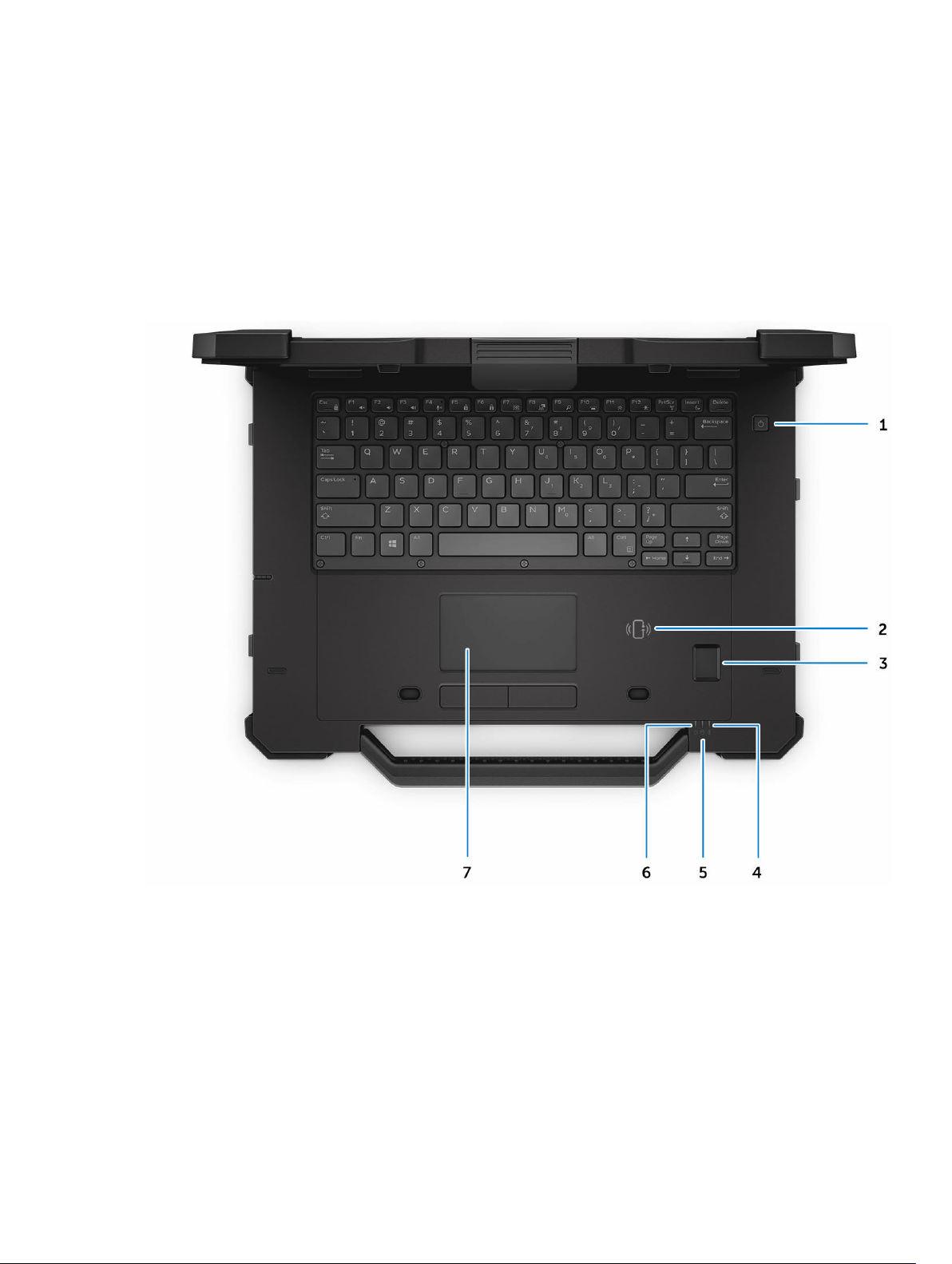
System top view
2
Figure 1. System top view
1. power button 2. contactless Smart card reader
3. fingerprint reader 4. battery status light
5. hard drive status light 6. power status light
7. touchpad
12
Page 13
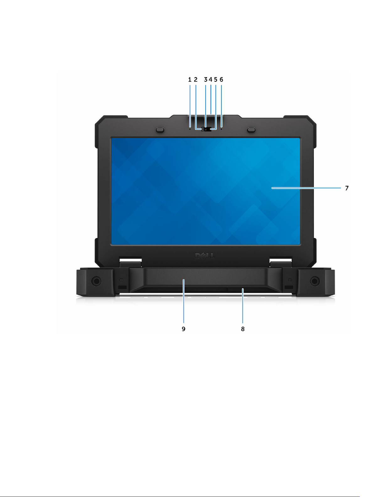
System front view
Figure 2. System front view
1. microphone 2. privacy shutter (optional)
3. camera (optional) 4. display latch
5. camera status light (optional) 6. microphone
7. outdoor readable display/touchscreen 8. speaker
9. handle
13
Page 14
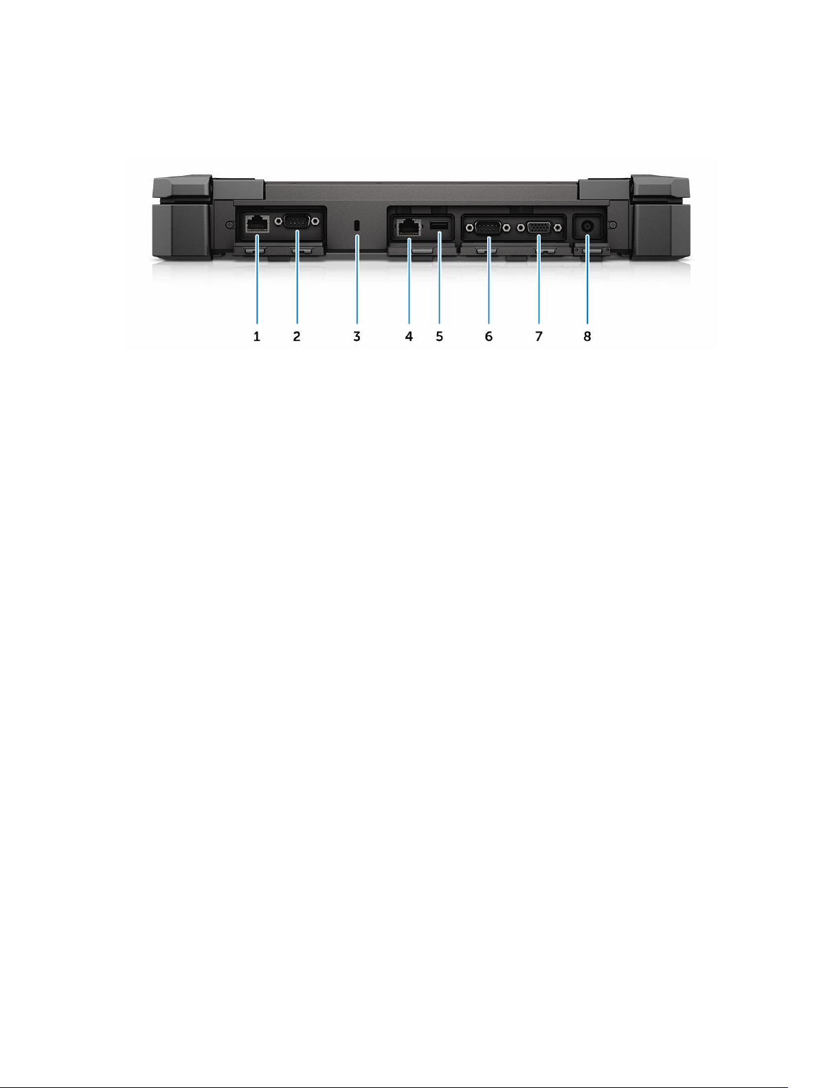
System back view
Figure 3. System back view
1. network port 2. serial port
3. security cable slot 4. network port
5. USB 2.0 port 6. serial port
7. VGA port 8. power connector
14
Page 15
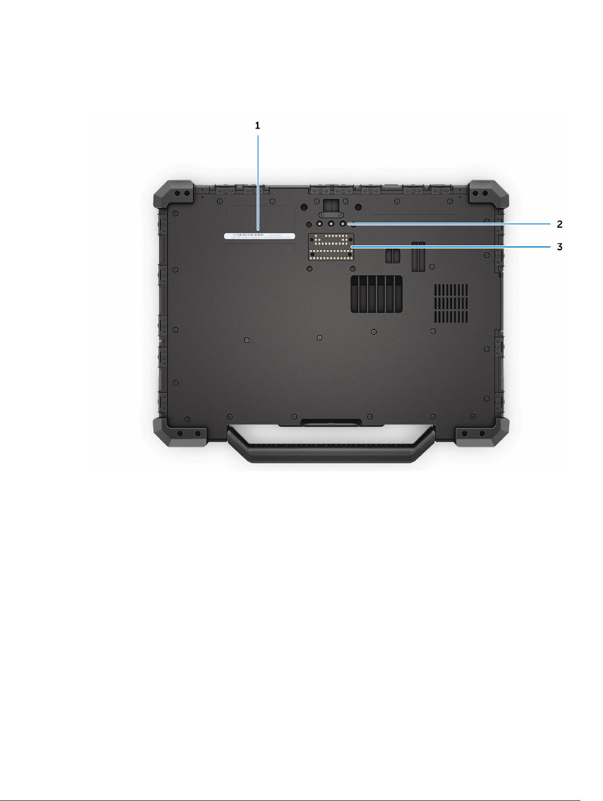
System base view
Figure 4. System base view
1. service tag 2. radio frequency pass-through connectors
3. docking device connector
15
Page 16
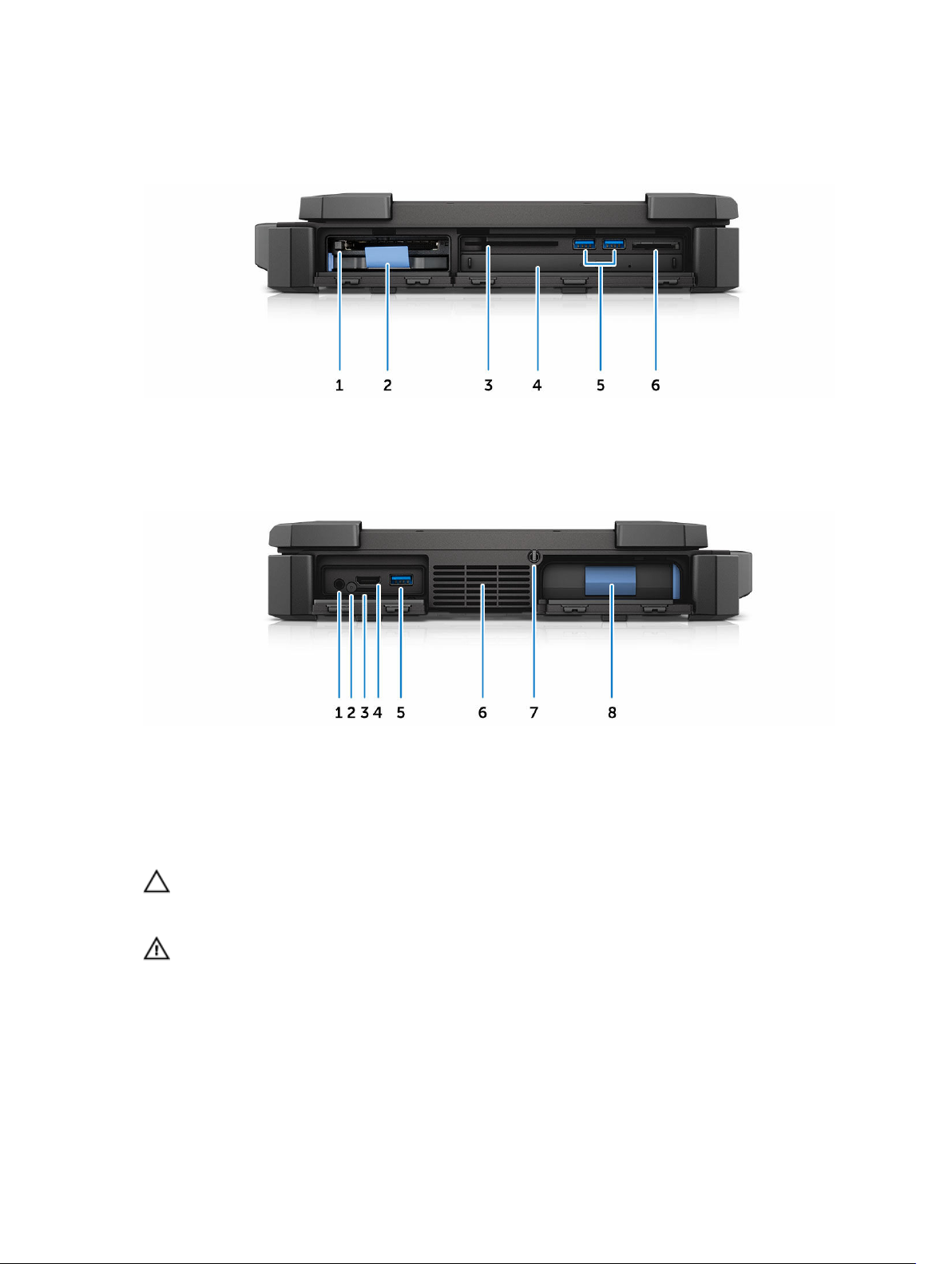
System side view
Figure 5. System side view — right
1. ExpressCard reader/PCMCIA (optional) 2. hard drive
3. Smart card reader 4. optical drive (optional)
5. USB 3.0 ports 6. memory card reader
Figure 6. System side view — left
1. audio port 2. SIM card security screw
3. SIM card slot 4. HDMI port
5. USB 3.0 port with PowerShare 6. QuadCool sealed thermal chamber
7. stylus 8. battery
CAUTION: EXPLOSION HAZARD—External connections (power adapter port, HDMI port, USB
ports, RJ45 port, serial ports, audio port, Smart Card reader slot, SD card reader slot, Express
Card reader slot, PC card reader slot, SIM card slot) should not to be used in a hazardous location.
WARNING: Do not block, push objects into, or allow dust to accumulate in the air vents. Do not
store your Dell computer in a low-airflow environment, such as a closed briefcase, while it is
running. Restricting the airflow can damage the computer. The computer turns on the fan when
the computer gets hot. Fan noise is normal and does not indicate a problem with the fan or the
computer.
16
Page 17
Removing and installing components
This section provides detailed information on how to remove or install the components from your
computer.
Recommended tools
The procedures in this document require the following tools:
• Small flat blade screwdriver
• Phillips #0 screwdriver
• Phillips #1 screwdriver
• Hex screwdriver
• Small plastic scribe
Press latch doors
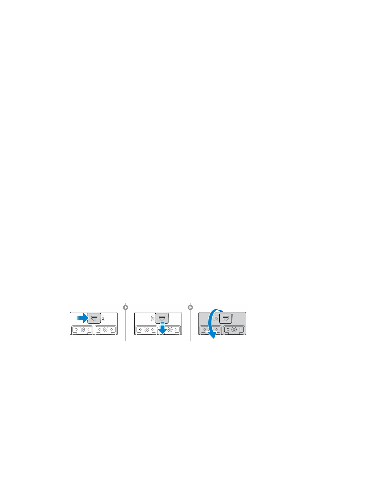
Opening the press latch doors
The computer includes eight press latch doors:
• Four on the back of the computer
• Two on the right side of the computer
• Two on the left side of the computer
3
1. Slide the latch until the unlock icon is visible.
2. Press the latch and open the press latch door in the downward direction.
Closing the press latch doors
1. Close the latch door back by pressing it toward the computer.
2. To lock the latch doors, slide the latch until the lock icon is visible.
17
Page 18
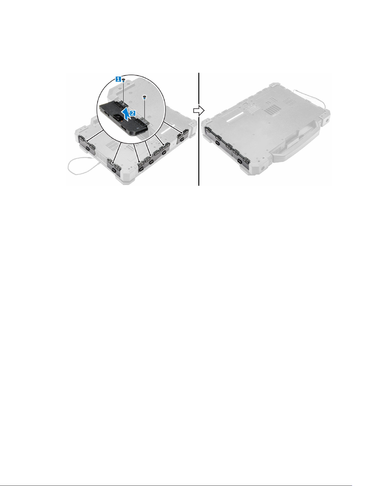
Removing the press latch doors
Remove the screws that secure the press-latch door and lift it from the computer [1,2].
Installing the press latch doors
1. Align the press latch door with the screw holes on the computer.
2. Tighten the screws to secure the press latch door.
Stylus and tether
Removing the stylus and tether
1. Pull the stylus out from the slot on the computer [1].
2. Release and remove the tether from the computer [2].
18
Page 19
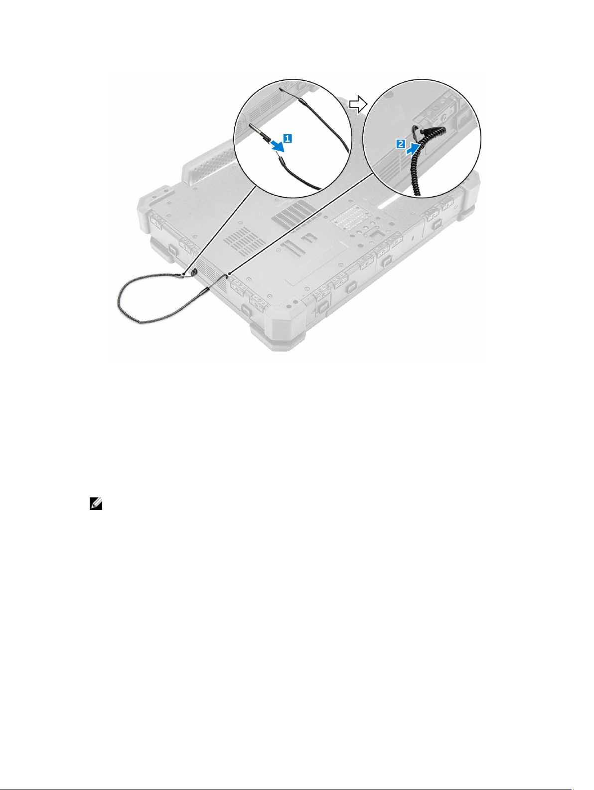
Installing the stylus and tether
1. Install the tether to the computer.
2. Insert the stylus into the slot and push it inwards.
Battery
Your system ships with a non-hot swappable battery. You also have an option to select a hot swap
battery.
NOTE: The battery is a field replaceable unit.
To check if your battery is a hot swap battery, go to System Setup → General → System
Information screen. The battery is not a customer replaceable part. If the hot swap battery is
installed, the optical drive is removed.
Hot swap battery
This section explains what happens when you swap the battery.
The BIOS allows 1 minute to swap the hot swap battery if there is sufficient charge and the temperature is
0º–60º C. When swapping the battery, the LCD, backlight and all LEDs turn off and the processor enters
a low power state to reduce system power. The battery LED flashes green/amber (once per second) for
the first 45 seconds. For the last 15 seconds, the green/amber flashes at a faster rate to indicate that the
swap time limit is near. If the 1-minute time is exceeded, the unit attempts to enter the Sleep (S3) state. If
19
Page 20
the user has disabled S3 or the OS fails to enter S3 entering Sleep is not guaranteed. When the system
enters the sleep (S3) state, the battery LED continues to flash green/amber at the faster rate to indicate to
the user that a power source needs to be installed.
If the hot swap battery is not charged to a sufficient level or the temperature is outside the mentioned
range and the user performs a hot swap, the BIOS puts the system into the Sleep (S3) state and flashes
the battery LED at a faster green/amber rate.
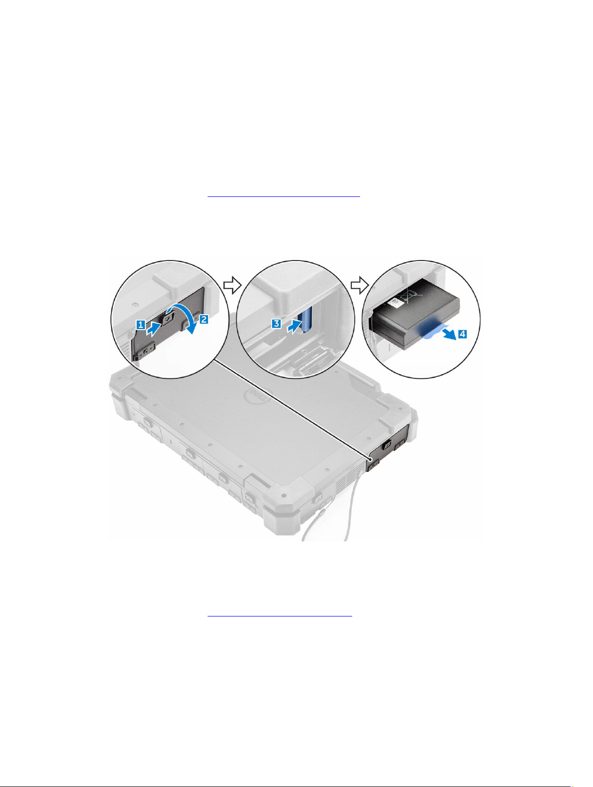
Removing the battery
1. Follow the procedure in Before working inside your computer.
2. To remove the battery:
a. Slide and open the battery bay press latch door [1, 2].
b. Press the blue battery release tab to release the battery [3].
c. Pull the blue tab on the battery to remove the battery from the computer [4].
Installing the battery
1. Insert the battery into the battery bay.
2. Close the battery bay press latch door.
3. Follow the procedure in After working inside your computer.
20
Page 21
Base cover
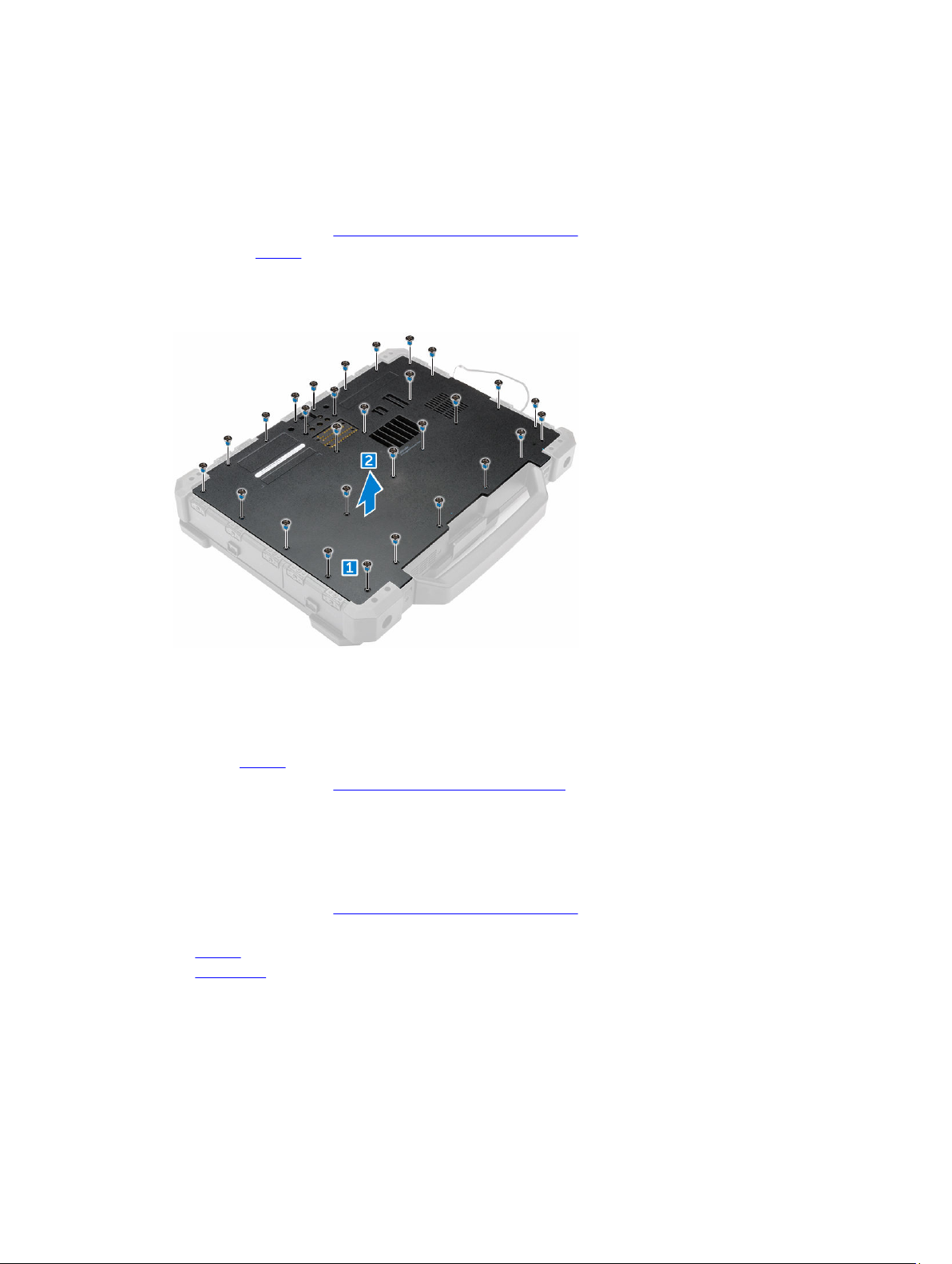
Removing the base cover
1. Follow the procedure in Before working inside your computer.
2. Remove the battery.
3. To remove the base cover:
a. Remove the screws that secure the base cover to the chassis.
b. Lift the base cover and remove it from the computer.
Installing the base cover
1. Place the base cover on the computer.
2. Secure the base cover to the computer by using the screws.
3. Install the battery.
4. Follow the procedure in After working inside your computer.
Battery connector
Removing the battery connector
1. Follow the procedure in Before working inside your computer.
2. Remove the:
a. battery
b. base cover
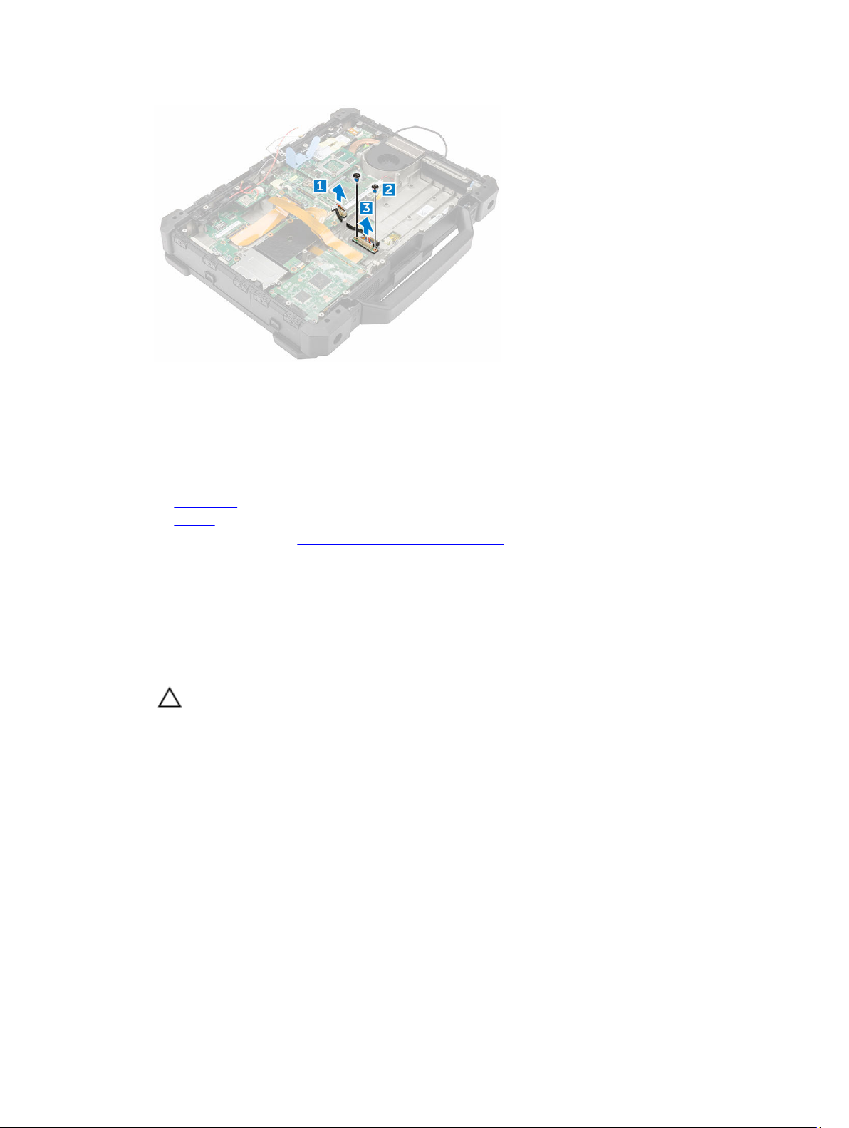
3. To remove the battery connector:
a. Disconnect the battery connector cable from the system board [1].
b. Remove the screws that secure the battery connector board to the computer [2].
c. Lift and remove the battery connector board from the computer [3].
21
Page 22
Installing the battery connector
1. Install the battery connector board on the computer.
2. Secure the battery connector to the computer by using the screws.
3. Connect the battery connector cable to the slot on the system board.
4. Install the:
a. base cover
b. battery
5. Follow the procedure in After working inside your computer.
Hard drive
Removing the hard drive
1. Follow the procedure in Before working inside your computer.
2. To remove the hard drive:
CAUTION: Turn off the computer before you remove the hard drive.
a. Unlock the hard drive press latch door and lift it up to open it.
b. Release the hard drive by pressing the blue hard drive release latch [1].
c. Pull the hard drive out of the computer using the hard drive pull loop [2].
22
Page 23
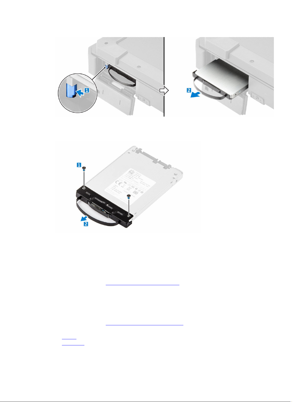
3. To remove the hard drive pull loop from the hard drive assembly:
a. Remove the screws that secure the hard drive pull loop to the hard drive assembly [1].
b. Pull the hard drive pull loop and separate it from the hard drive assembly [2].
Installing the hard drive
1. Attach the hard drive pull loop to the hard drive assembly.
2. Install the screws that secure the hard drive pull loop to the hard drive assembly.
3. Slide the hard drive into the hard drive bay.
4. Close the hard drive bay press latch door.
5. Follow the procedure in After working inside your computer.
Solid State Drive (SSD)
Removing the SSD
1. Follow the procedure in Before working inside your computer.
2. Remove the:
a. battery
b. base cover
23
Page 24
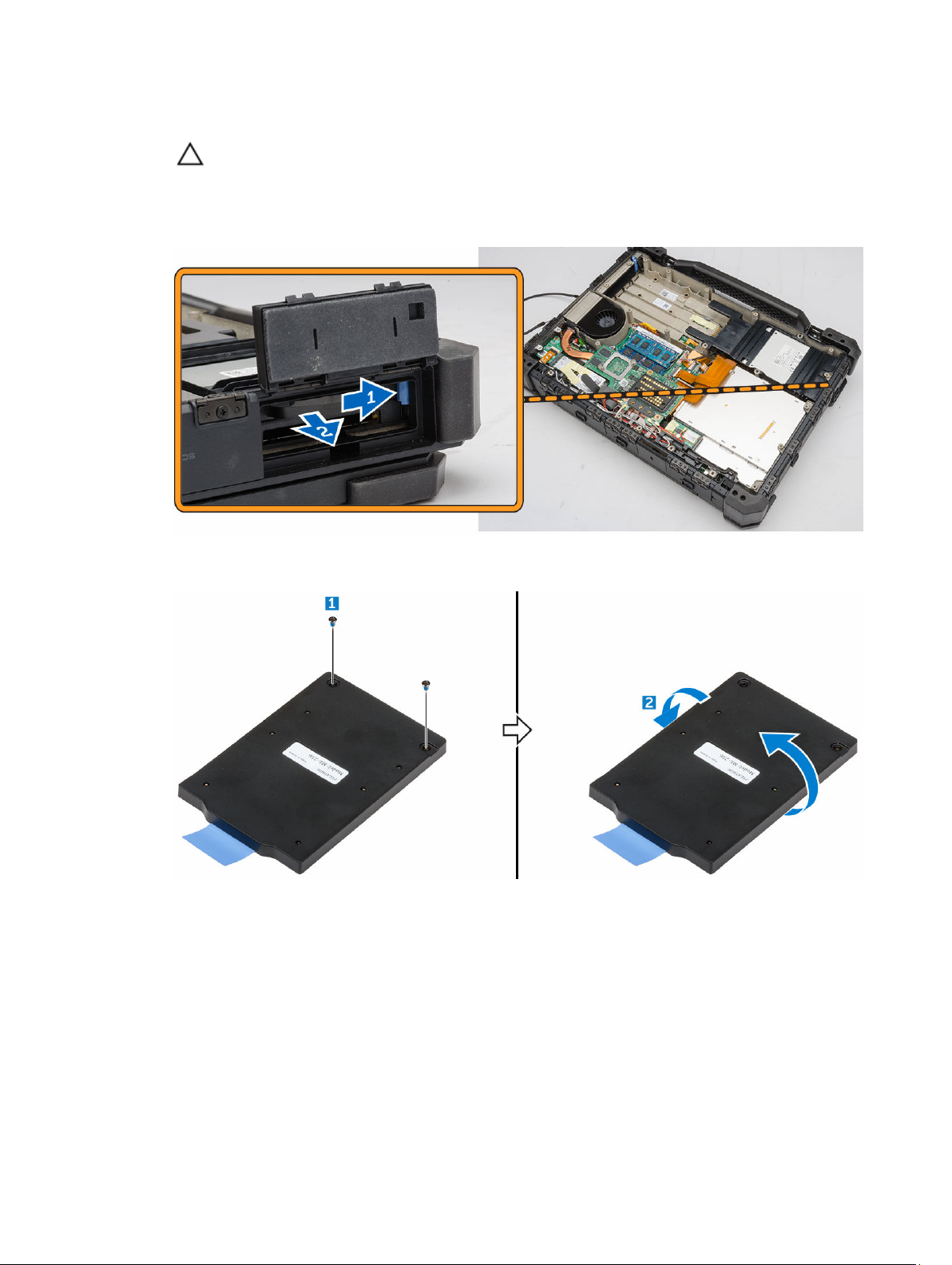
3. Perform the following steps:
CAUTION: Turn off the computer before you remove the hard drive.
a. Unlock the SSD press latch door and lift it upwards to open it.
b. Release the SSD by opening the blue hard drive release latch.
c. Slide the SSD out of the computer by using the pull tab.
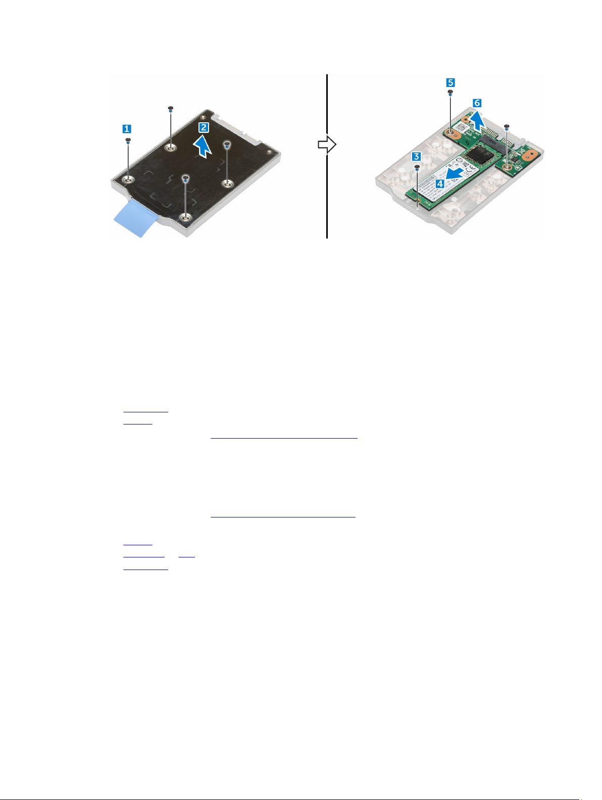
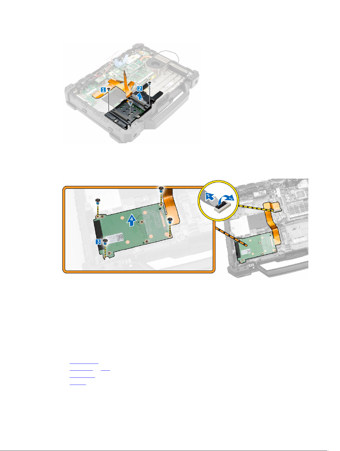
4. Remove the screws that secure the SSD plate [1]
5. Turn the SSD plate over [2].
6. To remove the SSD:
a. Remove the screws that secure the SSD plate cover [1].
b. Lift and remove the SSD plate cover [2].
c. Remove the screw that secures the SSD to the SSD plate [3].
d. Slide the SSD and disconnect it from the connector on the SSD controller board[4].
e. Remove the screws that secure the SSD controller board to the SSD plate [5].
f. Lift and remove the SSD controller board from the SSD plate.
24
Page 25
Installing the SSD
1. Insert the SSD controller board into the SSD plate.
2. Secure the SSD controller board to the SSD plate by using the screws.
3. Insert the SSD into the connector on the SSD controller board.
4. Secure the SSD to the SSD plate by using the screw.
5. Install the SSD plate over the SSD cover and secure it by using the screws.
6. Turn over the SSD and secure the SSD plate cover by using the screws.
7. Insert the SSD into the SSD slot on the computer.
8. Close the hard drive/SSD bay press latch door.
9. Install the:
a. base cover
b. battery
10. Follow the procedure in After working inside your computer.
Handle
Removing the handle
1. Follow the procedure in Before working inside your system..
2. Remove the:
a. battery
b. hard drive or SSD
c. base cover
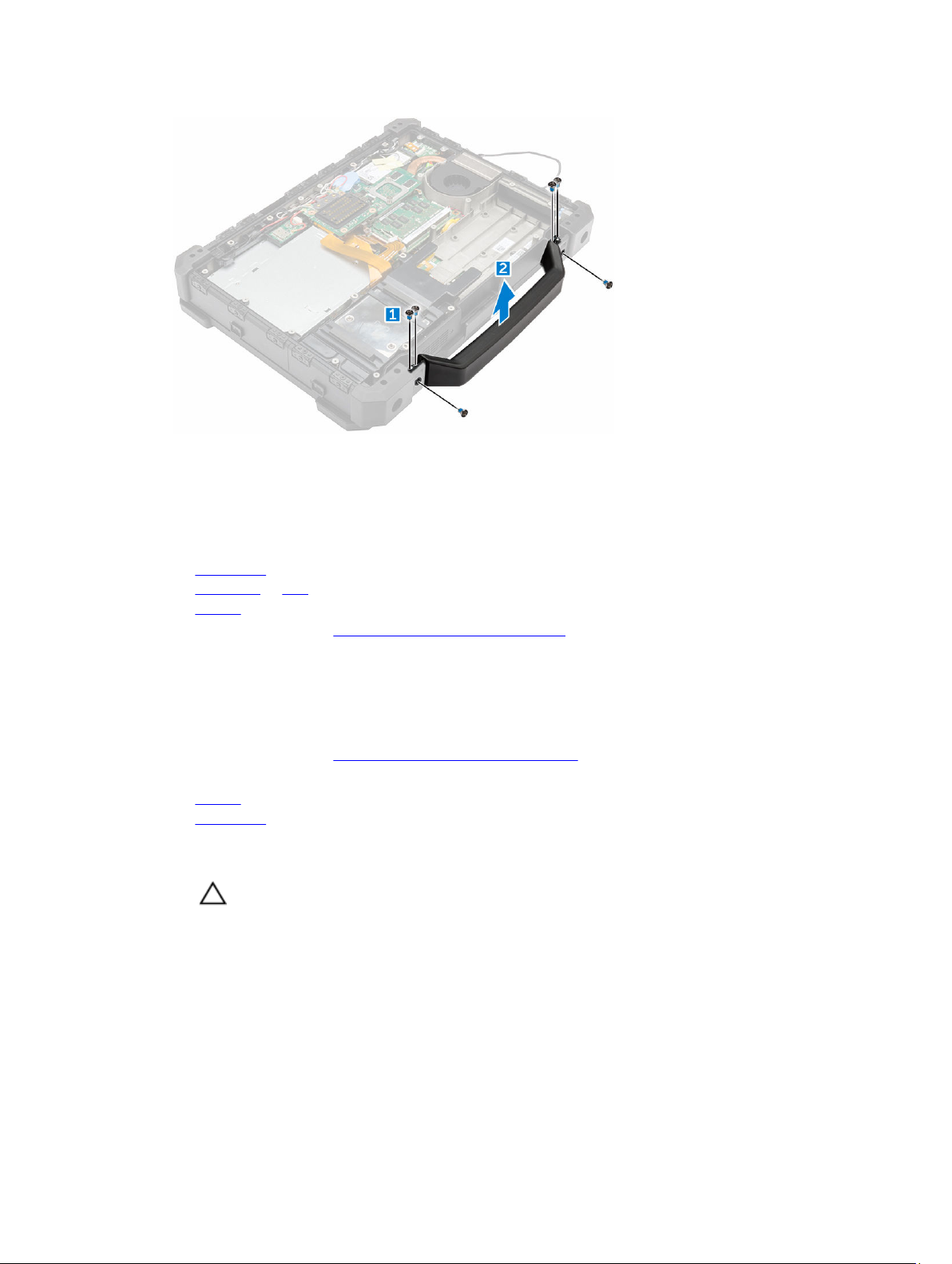
3. To remove the handle:
a. Remove the screws that secure the handle to the computer [1].
b. Lift and remove the handle from the computer [2].
25
Page 26
Installing the handle
1. Align the handle on the computer.
2. Secure the handle to the computer by using the screws.
3. Install the:
a. base cover
b. hard drive or SSD
c. battery
4. Follow the procedure in After working inside your computer.
Docking board
Removing the docking board
1. Follow the procedure in Before working inside your computer.
2. Remove the:
a. battery
b. base cover
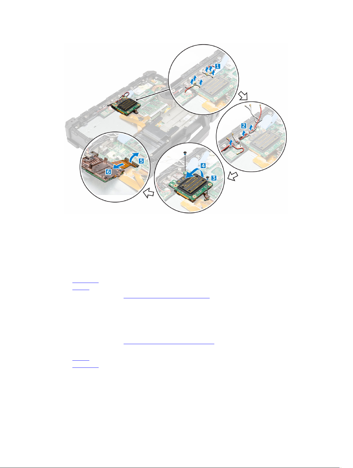
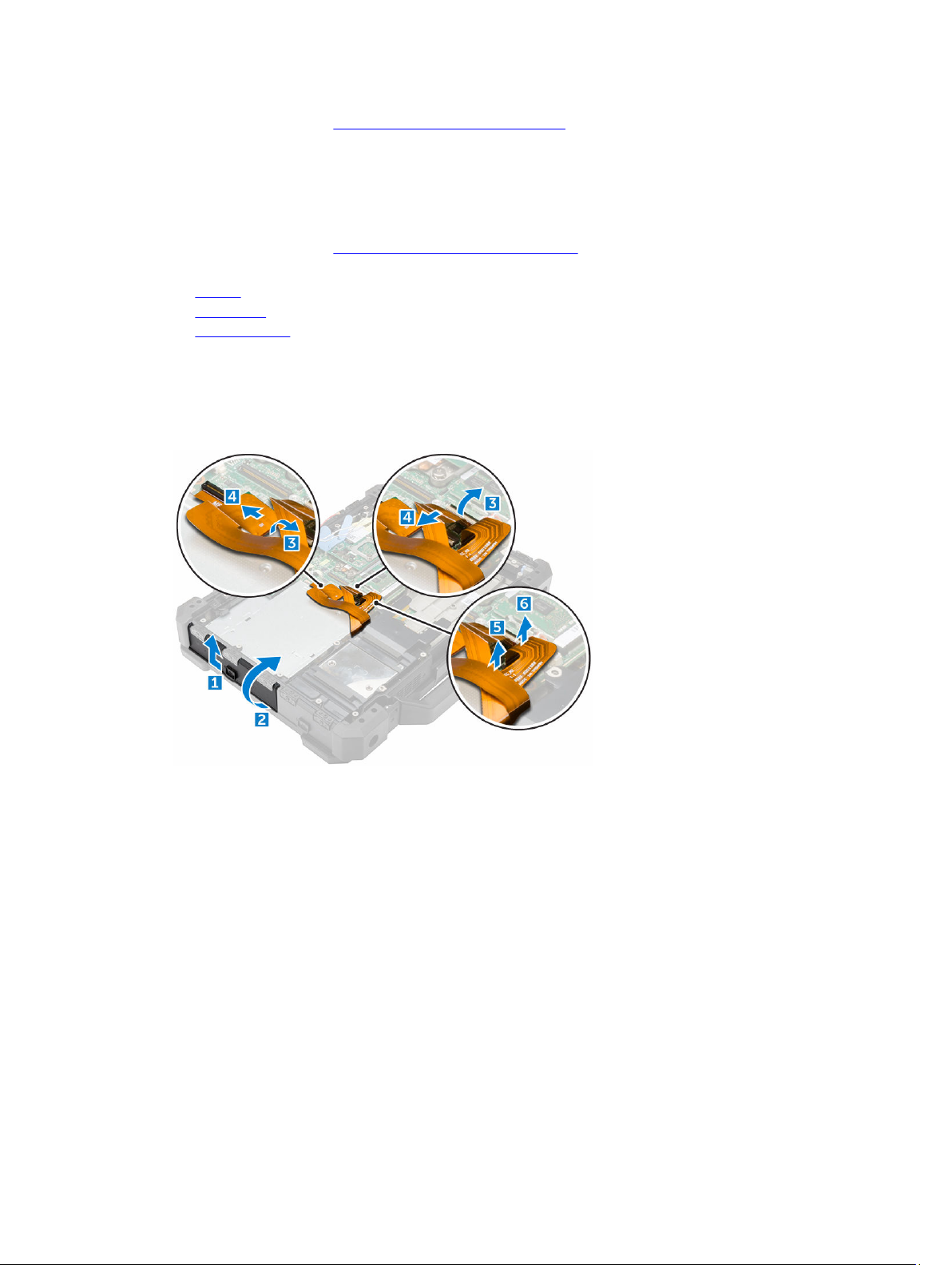
3. To remove the docking board:
a. Disconnect the docking board antenna cables [1].
CAUTION: Please exercise caution while disconnecting the antenna cables. Improper
removal may result in damage or breakage of the antenna cables.
b. Release the docking board antenna cables from the routing channels [2].
c. Remove the screws that secure the docking board to the system board and turn it over in the
direction indicated [3, 4].
d. Disconnect the docking board connector cable by lifting the cable release tab [5, 6].
e. Lift and remove the docking board from the computer.
26
Page 27
Installing the docking board
1. Connect the docking board connector cable to the system board.
2. Align the docking board with the system board and install the screws that secure it.
3. Route the docking board antenna cables through the routing channels.
4. Connect the antenna cables to the corresponding location on the docking board.
5. Install the:
a. base cover
b. battery
6. Follow the procedure in After working inside your computer.
Memory module
Removing the memory module
1. Follow the procedure in Before working inside your computer.
2. Remove the:
a. battery
b. base cover
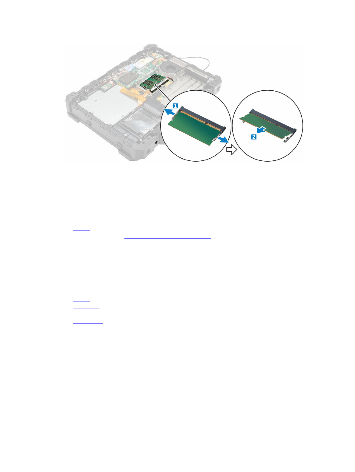
3. Pull the clips securing the memory module until the memory module pops up [1].
4. Remove the memory module from the memory module socket[2].
27
Page 28
Installing the memory module
1. Align the keyed notch on the memory module with the memory module socket.
2. Insert the memory module into the memory module socket.
3. Press the memory module until it clicks into place.
4. Install the:
a. base cover
b. battery
5. Follow the procedure in After working inside your computer.
ExpressCard module
Removing the ExpressCard module
1. Follow the procedure in Before working inside your computer.
2. Remove the:
a. battery
b. base cover
c. hard drive or SSD
d. optical drive
3. To remove the ExpressCard shroud:
a. Remove the screws that secure the ExpressCard shroud [1].
b. Lift and remove the ExpressCard shroud from the computer .
28
Page 29
4. To remove the ExpressCard board:
a. Disconnect the ExpressCard board connector cable from the system board [1, 2].
b. Remove the screws that secure the ExpressCard board [3].
c. Lift and remove the ExpressCard board from the computer [4].
Installing the ExpressCard module
1. Insert the ExpressCard board into the slot on the chassis.
2. Connect the ExpressCard board connector cable to the system board.
3. Install the screws that secure the ExpressCard board to the system board.
4. Install the ExpressCard shroud.
5. Install the screws that secure the ExpressCard shroud to the ExpressCard board.
6. Connect the ExpressCard board shroud cable to the system board.
7. Install the:
a. optical drive
b. hard drive or SSD
c. base cover
d. battery
29
Page 30
8. Follow the procedure in After working inside your computer.
Optical drive
Removing the optical drive
1. Follow the procedure in Before working inside your computer.
2. Remove the:
a. battery
b. base cover
c. docking board
3. Unlock the optical drive bay press latch door and open it [1, 2].
4. To disconnect the ExpressCard cables and the shroud cables:
a. Lift the release tab and lift the cable out of the connector [3, 4].
b. Remove the ExpressCard cable by lifting the cable out of the connector on the system board [5,
6].
5. To remove the optical drive:
a. Remove the screws that secure the optical drive to the system board [1].
b. Slide the optical drive forward until the optical drive cable is visible [2].
c. Lift the release tab [3] and lift the optical drive cable out of the connector on the system board
[4].
d. Slide the optical drive out of the optical drive slot on the computer [5].
30
Page 31

6. To remove the optical drive connector:
a. Remove the screw that secures the optical drive connector [1].
b. Pull the optical drive connector [2].
c. Remove the optical drive connector from the computer.
Installing the optical drive
1. Install the optical drive bracket to the optical drive.
2. Secure it to the optical drive by using the screws.
3. Insert the optical drive through the press latch door until it is firmly aligned to the optical drive
connector on the system board.
4. Install the screws that secure the optical drive to the system board.
5. Connect the optical drive cable.
6. Connect the ExpressCard cables and the shroud cables.
7. Install the:
a. docking board
b. base cover
c. battery
31
Page 32

8. Follow the procedure in After working inside your computer.
Graphics Processing Unit (GPU)
Removing the GPU
1. Follow the procedure in Before working inside your computer.
2. Remove the:
a. battery
b. base cover
3. To remove the GPU:
a. Remove the screws that secure the GPU module to the heat sink [1].
b. Remove the support bracket that secures the GPU module to the heat sink [2].
c. Remove the screws that secure the GPU module to the system board [3].
d. Using the pull tabs lift and remove the GPU module from the computer [4].
Installing the GPU
1. Align and connect the GPU module to the slot on the heat sink.
2. Secure the GPU module to the system board by using the screws.
3. Place the support bracket on the GPU module.
4. Install the screws that secure the GPU module.
5. Install the:
a. base cover
b. battery
6. Follow the procedure in After working inside your computer.
32
Page 33

Heat sink
Removing the heat sink
1. Follow the procedure in Before working inside your computer.
2. Remove the:
a. battery
b. base cover
c. optional GPU module
3. To remove the heat sink:
a. Loosen the screws that secure the heat sink to the system board [1, 2, 3, 4].
NOTE: Loosen the screws in the order of the callout numbers [1, 2, 3, 4]. These screws are
retention screws and cannot be fully removed.
b. Lift and remove the heat sink from the computer [5].
4. Clean the old thermal grease and apply a replacement thermal pad (if available).
Installing the heat sink
1. Align the heat sink with the system board.
2. Secure the heat sink to the system board by using the screws.
NOTE: Secure the screws in the order of the callout numbers [1, 2, 3, 4].
3. Install the:
a. GPU module (optional)
b. base cover
c. battery
4. Follow the procedure in After working inside your computer.
33
Page 34

System fan
Removing the system fan
1. Follow the procedure in Before working inside your computer.
2. Remove the:
a. battery
b. base cover
3. To remove the system fan:
a. Disconnect the system fan connector cable from the system board [1, 2].
b. Remove the screws that secure the system fan to the computer [3].
c. Lift and remove the system fan from the computer [4].
Installing the system fan
1. Align the system fan on the chassis.
2. Secure the system fan to the computer by using the screws.
3. Connect the system fan connector cable to the system board connector.
4. Install the:
a. base cover
b. battery
5. Follow the procedure in After working inside your computer.
Global Positioning System (GPS)
Removing the GPS module
1. Follow the procedure in Before working inside your computer.
2. Remove the:
a. battery
34
Page 35

b. base cover
3. To remove the GPS module:
a. Disconnect the GPS antenna cable from the module [1].
b. Release the GPS module from the connector on the system board [2].
c. Pull the GPS module retention latch upwards and remove the GPS module from the computer [3,
4].
Installing the GPS module
1. Align the GPS module with the connector on the system board.
2. Insert the GPS module into the slot.
3. Connect the GPS module antenna cable.
4. Install the:
a. base cover
b. battery
5. Follow the procedure in After working inside your computer.
USH daughter board
Removing the USH daughter board
1. Follow the procedure in Before working inside your computer.
2. Remove the:
a. battery
b. base cover
c. hard drive or SSD
d. ExpressCard
3. To remove the USH daughter board:
a. Lift the release tab and pull the USH daughter board connector cable to disconnect it [1, 2].
b. Remove the screws that secure the USH daughter board to the chassis [3].
c. Turn the board over [4].
35
Page 36

d. Disconnect the other USH daughter board cable connectors [ 5, 6]
e. Remove the USH daughter board from the computer.
Installing the USH daughter board
1. Connect the USH daughter board connector cables at the bottom of the USH daughter board and
turn the board over.
2. Align the USH daughter board with the slot on the computer.
3. Install the screws that secure the USH daughter board to the system board.
4. Connect the USH daughter board connector cable on top of the USH daughter board.
5. Install the:
a. ExpressCard
b. base cover
c. hard drive or SSD
d. battery
36
Page 37

6. Follow the procedure in After working inside your computer.
LED board
Removing the LED board
1. Follow the procedure in Before working inside your computer.
2. Remove the:
a. battery
b. hard drive or SSD
c. base cover
d. ExpressCard
3. To remove the LED board:
a. Lift the release tab and disconnect the LED board connector cable [1, 2].
b. Remove the screws that secure the LED board to the chassis [3].
c. Lift and remove the LED board from the computer [4].
Installing the LED board
1. Align the LED board with the slot on the chassis and insert the LED board into the slot.
2. Install the screws that secure the LED board to the computer.
3. Connect the LED board connector cable to the system board.
4. Install the:
a. ExpressCard
b. base cover
c. hard drive or SSD
d. battery
5. Follow the procedure in After working inside your computer.
37
Page 38

Fingerprint reader
Removing the fingerprint reader board
1. Follow the procedure in Before working inside your computer.
2. Remove the:
a. battery
b. hard drive or SSD
c. base cover
d. ExpressCard
3. To remove the fingerprint reader:
a. Remove the screws that secure the fingerprint reader cover [1].
b. Lift the cover and remove it to expose the fingerprint reader board [2].
c. Lift the release tab and disconnect the fingerprint reader cable [3, 4].
d. Lift and remove the fingerprint reader board from the computer [5].
Installing the fingerprint reader board
1. Insert the fingerprint reader board into the slot on the computer.
2. Connect the fingerprint reader board cable to the connector.
3. Secure the metal cover to fingerprint reader board by using the screws.
4. Install the:
a. ExpressCard
b. base cover
c. hard drive
d. battery
5. Follow the procedure in After working inside your computer.
38
Page 39

Subscriber Identity Module(SIM) board
Removing the SIM board
1. Follow the procedure in Before working inside your Computer.
2. Remove the:
a. battery
b. base cover
c. docking board
3. To remove the SIM board:
a. Open the press latch door by pressing the release tab and lifting it [1, 2].
b. Remove the screws that secure the SIM board to the chassis. [3].
c. Disconnect the SIM board cable by lifting the release tab [4, 5].
d. Remove the screws that secure the SIM board to the system board [6].
e. Lift and remove the SIM board from the computer.
Installing the SIM board
1. Insert the SIM board into the slot on the computer.
2. Install the screws that secure the SIM board to the computer.
3. Connect the SIM board connector cable to the SIM board.
4. Install the screws that secure the SIM board from inside the connection area within the computer.
5. Close the press latch door by lowering the door until it clicks into place.
39
Page 40

6. Install the:
a. base cover
b. battery
c. docking board
7. Follow the procedure in After working inside your computer.
Coin cell battery
Removing the coin cell battery
1. Follow the procedure in Before working inside your computer.
2. Remove the:
a. battery
b. base cover
3. To remove the coin cell battery:
a. Peel the adhesive tape sticking the coin cell battery to the chassis.
b. Disconnect the coin cell battery cable from the system board [1].
c. Lift and remove the coin cell battery from the computer [2].
Installing the coin cell battery
1. Align the coin cell battery into the slot on the computer, affixing it to the chassis wall.
2. Connect the coin cell battery cable to the system board.
3. Install the:
a. base cover
b. battery
4. Follow the procedure in After working inside your computer.
40
Page 41

WLAN card
Removing the WLAN card
1. Follow the procedure in Before working inside your computer.
2. Remove the:
a. battery
b. base cover
3. To remove the WLAN card:
a. Disconnect the antenna cables from the WLAN card [1].
b. Remove the screw that secures the WLAN card [2].
c. Slide the card out of the card connector on the system board and remove it [3].
Installing the WLAN card
1. Insert the WLAN card into its connector on the system board.
2. Press the card down and install the screw that secures the WLAN card.
3. Connect the antenna cables on the WLAN card.
4. Install the:
a. base cover
b. battery
5. Follow the procedure in After working inside your computer.
WWAN card
Removing the WWAN card
1. Follow the procedure in Before working inside your computer.
2. Remove the:
a. battery
41
Page 42

b. base cover
3. To remove the WWAN card:
a. Disconnect the antenna cables from the WWAN card [1].
b. Remove the screw that secures the WWAN card [2].
c. Slide the card out of the card connector on the system board and remove it [3].
Installing the WWAN card
1. Insert the WWAN card into the connector on the system board.
2. Press the card down and install the screw that secures the WWAN card.
3. Connect the antenna cables on the WWAN card.
4. Install the:
a. base cover
b. battery
5. Follow the procedure in After working inside your computer.
RF cable holder
Removing the RF cable holder
1. Follow the procedure in Before working inside your computer.
2. Remove the:
a. battery
b. hard drive or SSD
c. optical drive
d. base cover
e. GPS board
f. WLAN card
g. docking board
3. To remove the RF cable holder:
a. Unroute the antenna cables from the cable routing clips [1].
42
Page 43

b. Remove the screw that secures the RF holder to the computer [2] [3].
c. Lift and remove the RF holder from the computer [3] [4].
Installing the RF holder
1. Place the RF holder on the computer.
2. Install the screws that secure the RF holder to the computer.
3. Connect the antenna cables.
4. Route the antenna cables.
5. Install the:
a. docking board
b. WLAN card
c. GPS board
d. optical drive
e. hard drive or SSD
f. base cover
g. battery
6. Follow the procedure in After working inside your computer.
43
Page 44

GPS holder
Removing the GPS holder
1. Follow the procedure in Before working inside your computer.
2. Remove the:
a. battery
b. hard drive or SSD
c. base cover
d. optical drive
3. To remove the GPS holder:
a. Disconnect the antenna cable and unroute it from the GPS holder [1].
b. Disconnect the GPS holder cable.
c. Remove the screw that secures the GPS holder to the computer [2].
d. Lift the GPS holder from the computer [3].
Installing the GPS holder
1. Insert the GPS holder into the slot on the computer.
2. Tighten the screw that secures the holder to the computer.
3. Connect the antenna cable and the GPS holder cable.
4. Install the:
a. optical drive
b. hard drive or SSD
c. base cover
d. battery
5. Follow the procedure in After working inside your computer.
44
Page 45

System board
Removing the system board
1. Follow the procedure in Before working inside your computer.
2. Remove the:
a. battery
b. hard drive or SSD
c. keyboard
d. keyboard door
e. base cover
f. docking board
g. optical drive
h. memory module
i. GPU module
j. heat sink
k. ExpressCard
l. GPS module
m. WLAN card
n. WWAN card
o. SIM board
p. GPS holder
q. RF holder
3. Disconnect the cables under the keyboard by pressing on the release tab and lifting it [1, 2, 3, 4].
4. To disconnect the DisplayPort cable:
a. Remove the screws that secure the display connector to the system board [1].
b. Lift and remove the metal bracket that covers the display connector [2].
c. Disconnect the display connector cable from the system board [3].
d. Remove the screws that secure the DisplayPort to the computer chassis [4].
45
Page 46

NOTE: All the cables connected to the system board should be disconnected prior to system
board removal.
5. To remove the system board from the chassis:
a. Remove the screws that secure the system board to the chassis [1].
b. Slide the system board forward and release any other additional connections at the bottom of the
chassis [2].
c. Disconnect the connector cable under the system board by pressing the release tab and lifting it.
d. Slide and remove the system board from the computer.
Installing the system board
1. Connect the system board connector cable to the system board and turn it around.
2. Align the system board into the chassis until it is firmly seated.
3. Install the screws that secure the system board to the chassis.
4. Install the screws that secure the DisplayPort press latch doors to the computer.
5. Connect the display cable to the system board.
6. Install the screws that secure the metal bracket to the display cable on the system board.
7. Turn the computer over and connect the cables under the keyboard to the system board.
46
Page 47

8. Install the:
a. SIM board
b. WWAN card
c. WLAN card
d. GPS module
e. ExpressCard
f. heat sink
g. GPU module
h. RF holder
i. GPS holder
j. memory module
k. optical drive
l. docking board
m. base cover
n. keyboard
o. keyboard door
p. hard drive or SSD
q. battery
NOTE: When the service technician replaces a system board, he should set the service tag once
the system starts up. This is a one time effort. If you fail to set the service tag, the system battery
will not charge. Therefore, it is very important that the service technician sets the correct
system service tag. If a wrong service tag is set, there is no way to reset it and the technician
will have to place order for another system board.
9. Follow the procedure in After working inside your computer.
Smart card module
Removing the Smart card module
1. Follow the procedure in Before working inside your computer.
2. Remove the:
a. battery
b. hard drive or SSD
c. keyboard
d. base cover
e. docking board
f. optical drive
g. memory module
h. GPU module
i. heat sink
j. ExpressCard
k. GPS module
l. WLAN card
m. WWAN card
n. SIM board
o. system board
3. To remove the Smart card module:
a. Lift the release tab and disconnect the smart card ribbon cable from the USH board [1,2].
47
Page 48

b. Remove the screws that secure the Smart card module to the computer [3].
c. Lift and remove the smart card module from the computer [4].
Installing the Smart card module
1. Align and insert the Smart card module into the slot on the computer.
2. Install the screws that secure the Smart card module to the computer.
3. Connect the Smart card ribbon cable to the USH board.
4. Install the:
a. system board
b. SIM board
c. WWAN card
d. WLAN card
e. GPS module
f. ExpressCard
g. heat sink
h. GPU module
i. memory module
j. optical drive
k. docking board
l. base cover
m. keyboard
n. hard drive or SSD
o. battery
5. Follow the procedure in After working inside your computer.
Palmrest
Removing the palmrest
1. Follow the procedure in Before working inside your computer.
2. Remove the:
a. battery
48
Page 49

b. hard drive or SSD
c. keyboard
d. base cover
e. docking board
f. optical drive
g. memory module
h. coin cell battery
i. GPU module
j. heat sink
k. ExpressCard
l. GPS module
m. WLAN card
n. WWAN card
o. fingerprint reader
p. SIM board
q. system board
r. SmartCard reader
3. To disengage the palmrest:
a. Remove the screws that secure the palmrest to the computer [1].
b. Turn the computer over.
4. To remove the palmrest from the computer:
a. Open the computer lid [1].
b. Lift the palmrest at the bottom of the touch pad buttons to release it from the computer [2].
c. Lift and remove the palmrest from the computer.
49
Page 50

Installing the palmrest
1. Insert the palmrest into the slot on the computer until it clicks into place.
2. Turn the computer over and install the screws that secure the palmrest to the computer.
3. Install the:
a. SmartCard reader
b. system board
c. SIM board
d. fingerprint reader
e. WWAN card
f. WLAN card
g. GPS module
h. coin cell battery
i. ExpressCard
j. heat sink
k. GPU module
l. memory module
m. optical drive
n. docking board
o. base cover
p. keyboard
q. hard drive or SSD
r. battery
4. Follow the procedure in After working inside your computer.
Input/Output(I/O) board
Removing the I/O board
1. Follow the procedure in Before working inside your computer.
2. Remove the:
a. battery
b. hard drive or SSD
50
Page 51

c. keyboard
d. base cover
e. docking board
f. optical drive
g. memory module
h. GPU module
i. heat sink
j. ExpressCard
k. GPS module
l. WLAN card
m. WWAN card
n. SIM board
o. system board
p. Smart card reader
3. To remove the I/O port:
a. Open the I/O port press latch door [1, 2].
b. Remove the thumb screws that secure the I/O port module to the computer [3].
4. To remove the I/O board:
a. Remove the screws that secure the I/O board module to the computer chassis [1].
b. Lift and remove the I/O board module from the computer [2].
51
Page 52

Installing the I/O board
1. Align the I/O board module with the slot on the computer by first sliding I/O port end through the
press latch door.
2. Connect the I/O board ribbon cable to the system board.
3. Install the screws that secure the I/O port to the computer and close the press latch door.
4. Install the thumb screws that secure the I/O board to the computer chassis.
5. Install the:
a. Smart card reader
b. system board
c. SIM board
d. WWAN card
e. WLAN card
f. GPS module
g. ExpressCard
h. heat sink
i. GPU module
j. memory module
k. optical drive
l. docking board
m. base cover
n. keyboard
o. hard drive or SSD
p. battery
6. Follow the procedure in After working inside your computer.
Keyboard
Removing the keyboard
1. Follow the procedures in Before working inside your computer.
2. Remove the battery.
3. To remove the keyboard:
a. Remove the screws that secure the keyboard to the computer [1].
b. Lift the edges and flip the keyboard towards the display [2].
52
Page 53

4. To remove the keyboard door:
a. Remove the screws that secure the keyboard door [1].
b. Lift and remove the keyboard door [2].
c. Disconnect the keyboard cables from the keyboard controller card by pressing on the lock tab
and lifting the connector [3 ,4, 5, 6].
d. Lift and remove the keyboard from the computer.
Installing the keyboard
1. Connect the keyboard flex cables to the connectors on the keyboard controller card.
2. Place the keyboard door over the slot on the computer chassis.
3. Tighten the screws that secure the keyboard door to the computer chassis.
4. Align the keyboard with the slot on the computer.
5. Install the screws to secure the keyboard to the computer.
6. Install the battery.
53
Page 54

7. Follow the procedure in After working inside your computer.
Keyboard control board
Removing the keyboard control board
1. Follow the procedure in Before working inside your computer.
2. Remove the:
a. battery
b. hard drive or SSD
c. keyboard
d. base cover
e. docking board
f. optical drive
g. memory module
h. GPU module
i. heat sink
j. ExpressCard
k. GPS module
l. WLAN card
m. WWAN card
n. SIM board
o. system board
3. To remove the keyboard control board:
a. Remove the screws that secure the keyboard control board [1].
b. Lift and remove the keyboard control board module from the computer [2].
Installing the keyboard control board
1. Align the keyboard control board with the slot on the computer.
2. Install the screws that secure the keyboard control board to the computer chassis.
3. Install the:
a. system board
54
Page 55

b. SIM board
c. WWAN card
d. WLAN card
e. GPS module
f. ExpressCard
g. heat sink
h. GPU module
i. memory module
j. optical drive
k. docking board
l. base cover
m. keyboard
n. hard drive or SSD
o. battery
4. Follow the procedure in After working inside your computer .
Speaker
Removing the speaker
1. Follow the procedure in Before working inside your computer.
2. Remove the:
a. battery
b. hard drive or SSD
c. keyboard
d. base cover
e. docking board
f. optical drive
g. memory module
h. GPU module
i. heat sink
j. ExpressCard
k. GPS module
l. WLAN card
m. WWAN card
n. SIM board
o. system board
3. To remove the speaker:
a. Remove the screws that secure the speaker module to the computer [1].
b. Unroute the speaker cable from its routing channel on the chassis [2].
c. Push the speaker module inwards and lift it to remove it from the computer [3].
55
Page 56

Installing the speaker
1. Insert the speaker into the slot on the computer.
2. Install the screws that secure the speaker to the computer.
3. Route the speaker cable along the routing channel on the chassis.
4. Install the:
a. system board
b. SIM board
c. WWAN card
d. WLAN card
e. GPS module
f. ExpressCard
g. heat sink
h. GPU module
i. memory module
j. optical drive
k. docking board
l. base cover
m. keyboard
n. hard drive or SSD
o. battery
5. Follow the procedure in After working inside your computer.
Power connector
Removing the power connector
1. Follow the procedure in Before working inside your computer.
2. Remove the:
a. battery
b. hard drive or SSD
c. keyboard
56
Page 57

d. base cover
e. docking board
f. optical drive
g. memory module
h. GPU module
i. heat sink
j. ExpressCard
k. GPS module
l. WLAN card
m. WWAN card
n. SIM board
o. system board
3. Lift the power connector and remove it from the computer.
Installing the power connector
1. Align the guide pins on the connector sides with the base of the chassis.
2. Insert the power connector into the slot on the chassis.
3. Press the power connector to secure it to the chassis.
4. Install the:
a. system board
b. SIM board
c. WWAN card
d. WLAN card
e. GPS module
f. ExpressCard
g. heat sink
h. GPU module
i. memory module
j. optical drive
k. docking board
l. base cover
m. keyboard
n. hard drive or SSD
57
Page 58

o. battery
5. Follow the procedure in After working inside your computer.
Display assembly
Removing the display assembly
1. Follow the procedure in Before working inside your computer.
2. Remove the:
a. battery
b. base cover
c. GPU module
d. heat sink
3. To disconnect the cables:
a. Unroute the display cables and antenna cables from the routing channels .
b. Disconnect the antenna cables from the modules.
c. Remove the screws that secure the display connector cable cover to the system board [1].
d. Disconnect the display connector cable from the system board [2, 3].
e. Remove the screws to remove the hinge covers [4].
f. Lift the hinge covers and remove them to expose the display cable routing and the display hinges
[5].
58
Page 59

4. To remove the display hinges:
a. Unroute the display cables completely from the routing channels. [1].
b. Remove the screws that secure the display hinges to the computer [2].
c. Turn the computer over to continue with the display removal [3].
5. To remove the display assembly:
a. Open the display [1].
b. Lift the display panel from the hinges and remove it from the computer [2].
59
Page 60

Installing the display assembly
1. Attach the display to the hinges on the computer.
2. Close the display and turn it over.
3. Route the display connector and antenna cables along the routing channels.
4. Install the screws that secure the display hinges to the computer chassis.
5. Install the display hinges.
6. Install the screws that secure the hinges to the computer.
7. Connect the display connector cable to the system board.
8. Place the hinge cover to conceal the connector cable.
9. Install the screws to secure the hinge cover.
10. Install the:
a. heat sink
b. GPU module
c. base cover
d. battery
11. Follow the procedure in After working inside your computer.
Display panel
Removing the display panel
1. Follow the procedure in Before working inside your computer.
2. Remove the battery.
3. To disengage the display panel from the display assembly:
a. Remove the screws that secure the display panel [1].
b. Turn the display assembly over so that screen is facing upwards.
c. Lift along the edges to separate the display panel from the display assembly [2].
4. To remove the display panel:
a. Disconnect the eDP cable from the display assembly [1].
b. Disconnect the camera connector cables from the display assembly [2, 3].
c. Remove the display panel from the display assembly [4].
60
Page 61

Installing the display panel
1. Connect the eDP connector cable to the display assembly.
2. Connect the camera cable connectors to the display assembly.
3. Attach the display panel to the display assembly.
4. Turn the display assembly over.
5. Press on the sides of the display panel to secure it.
6. Install the screws that secure the display panel to the display assembly.
7. Install the battery.
8. Follow the procedure in After working inside your computer.
Camera
Removing the camera
1. Follow the procedure in Before working inside your computer.
2. Remove the:
a. battery
b. display panel
3. To remove the camera:
a. Disconnect the camera cable from the assembly [1].
b. Remove the screws that secure the camera to the display panel [2].
c. Remove the adhesive tapes [3].
d. Lift and remove the camera from the computer [4].
61
Page 62

Installing the camera
1. Align and insert the camera into the slot on the display panel.
2. Install the screws that secure the camera to the display panel.
3. Connect the camera cable connector to the camera board.
4. Install the:
a. display panel
b. battery
5. Follow the procedure in After working inside your computer.
Touchscreen controller board
Removing the touch screen controller board
1. Follow the procedure in Before working inside your computer.
2. Remove the:
a. battery
b. display panel
3. To remove the touch screen controller board:
a. Peel the adhesive tape from the touch screen controller board [1].
b. Disconnect the touch screen controller board cable[2].
c. Remove the screw that secures the touch screen controller board to the display panel [3].
d. Lift and remove the touch screen controller board from the computer [4].
62
Page 63

Installing the touch screen controller board
1. Align and insert the touch screen controller board into the slot on the display panel.
2. Install the screws that secure the touch screen controller board to the display panel.
3. Connect the touch screen controller board connector to the controller board.
4. Replace the adhesive tape.
5. Install the:
a. display assembly
b. battery
6. Follow the procedure in After working inside your computer.
63
Page 64

4
System Setup
System Setup enables you to manage your computer hardware and specify BIOS level options. From the
System Setup, you can:
• Change the NVRAM settings after you add or remove hardware
• View the system hardware configuration
• Enable or disable integrated devices
• Set performance and power management thresholds
• Manage your computer security
Boot Sequence
Boot Sequence allows you to bypass the System Setup‐defined boot device order and boot directly to a
specific device (for example: optical drive or hard drive). During the Power-on Self Test (POST), when the
Dell logo appears, you can:
• Access System Setup by pressing F2 key
• Bring up the one-time boot menu by pressing F12 key
The one-time boot menu displays the devices that you can boot from including the diagnostic option.
The boot menu options are:
• Removable Drive (if available)
• STXXXX Drive
NOTE: XXX denotes the SATA drive number.
• Optical Drive
• Diagnostics
NOTE: Choosing Diagnostics, will display the ePSA diagnostics screen.
The boot sequence screen also displays the option to access the System Setup screen.
Navigation keys
NOTE: For most of the System Setup options, changes that you make are recorded but do not take
effect until you restart the system.
Keys Navigation
Up arrow Moves to the previous field.
64
Page 65

Keys Navigation
Down arrow Moves to the next field.
Enter Selects a value in the selected field (if applicable) or follow the link in the field.
Spacebar Expands or collapses a drop‐down list, if applicable.
Tab Moves to the next focus area.
NOTE: For the standard graphics browser only.
Esc Moves to the previous page until you view the main screen. Pressing Esc in the
main screen displays a message that prompts you to save any unsaved changes
and restarts the system.
F1 Displays the System Setup help file.
System Setup overview
System Setup allows you to:
• Change the system configuration information after you add, change, or remove any hardware in your
computer.
• Set or change a user-selectable option such as the user password.
• Read the current amount of memory or set the type of hard drive installed.
Before you use System Setup, it is recommended that you write down the System Setup screen
information for future reference.
CAUTION: Unless you are an expert computer user, do not change the settings for this program.
Certain changes can cause your computer to work incorrectly.
General screen options
This section lists the primary hardware features of your computer.
Option Description
System
Information
• System Information: Displays BIOS Version, Service Tag, Asset Tag, Ownership
Tag, Ownership Date, Manufacture Date, and the Express Service Code, Hot
Swap Battery (if installed).
• Memory Information: Displays Memory Installed, Memory Available, Memory
Speed, Memory Channels Mode, Memory Technology, DIMM A Size, DIMM B
Size.
• Processor Information: Displays Processor Type, Core Count, Processor ID,
Current Clock Speed, Minimum Clock Speed, Maximum Clock Speed,
Processor L2 Cache, Processor L3 Cache, HT Capable, and 64-Bit technology.
• Device Information: Displays Primary Hard Drive, MiniCard Device, ODD Device,
Dock eSATA Device, LOM MAC Address, Video Controller, Video BIOS Version,
Video Memory, Panel Type, Native Resolution, Audio Controller, Wi-Fi Device,
WiGig Device, Cellular Device, Bluetooth Device.
65
Page 66

Option Description
Battery
Information
Boot Sequence
Advanced Boot
Options
Date/Time Allows you to change the date and time.
Displays the battery status and the type of AC adapter connected to the computer.
Boot Sequence Allows you to change the order in which the computer
attempts to find an operating system. The options are:
• Internal HDD
• USB Storage Device
• CD/DVD/CD-RW Drive
• Onboard NIC
By default, all the options are checked. You can also clear
any option or change the boor order.
Boot List Options Allows you to change the boot list option:
• Legacy
• UEFI (enabled by default)
Allows you the legacy option ROMs to load. By default, the Enable Legacy Option
ROMs is disabled.
System Configuration screen options
Option Description
Integrated NIC You can configure the integrated network controller. The options are:
• Enable UEFI Network Stack
• Disabled
• Enabled
• Enabled w/PXE. This option is enabled by default.
Onboard
Unmanaged NIC
Parallel Port You can configure the parallel port on the docking station. The options are:
You can control the on-board USB LAN controller. The options are:
• Disabled
• Enabled. This option is enabled by default.
• Disabled
• AT. This option is enabled by default.
• PS2
• ECP
66
Page 67

Option Description
Serial Port 1 You can configure the integrated serial port. The options are:
• Disabled
• COM1. This option is enabled by default.
• COM3
Serial Port 2 You can configure the integrated serial port. The options are:
• Disabled
• COM2. This option is enabled by default.
• COM4
SATA Operation You can configure the internal SATA hard drive controller. The options are:
• Disabled
• AHCI
• RAID On. This option is enabled by default.
Drives You can configure the SATA drives on board. All drives are enabled by default. The
options are:
• SATA-0
• SATA-2
SMART Reporting You can control whether hard drive errors for integrated drives are reported during
system startup. This technology is part of the SMART (Self-Monitoring Analysis and
Reporting Technology) specification. The option is:
• Enable SMART Reporting. This option is disabled by default.
USB/Thunderbolt
Configuration
You can configure the integrated USB controller. If Boot Support is enabled, the
system is allowed to boot any type of USB Mass Storage Devices (hard drive or
memory key).
If the USB port is enabled, the device attached to this port is enabled and available
for the OS.
If the USB port is disabled, the OS cannot see any device attached to this port.
The options are:
• Enable USB Boot Support
• Enable External USB Ports
• Disable Docking Station Devices except video
NOTE: The USB keyboard and mouse always work in the BIOS setup
irrespective of these settings.
67
Page 68

Option Description
USB PowerShare You can configure the USB PowerShare feature behavior. This option allows you to
charge external devices using the stored system battery power through the USB
PowerShare port.
This option is unchecked by default.
Audio You can enable or disable the integrated audio controller.
The Enable Audio option is selected by default.
Keyboard
Illumination
Keyboard
Backlight Timeout
on AC
Keyboard
Backlight Timeout
on Battery
You can choose the operating mode of the keyboard illumination feature. The
keyboard brightness level can be set from 25 % to 100%. The options are:
• Disabled
• Dim. This option is enabled by default.
• Bright
The Keyboard Backlight with AC option does not affect the main keyboard
illumination feature. Keyboard Illumination continues to support the various
illumination levels. The options are:
• 5 seconds
• 10 seconds. This option is selected by default.
• 15 seconds
• 30 seconds
• 1 minute
• 5 minute
• 15 minute
• Never
The Keyboard Backlight with Battery option does not affect the main keyboard
illumination feature. Keyboard Illumination continues to support the various
illumination levels. The options are:
• 5 seconds
• 10 seconds. This option is selected by default.
• 15 seconds
• 30 seconds
• 1 minute
• 5 minute
• 15 minute
• Never
RGB Keyboard
Backlight
Touchscreen You can enable or disable the touchscreen.
68
You can configure the RGB keyboard backlight feature. There are six available
colors: four preset colors (white, red, green, and blue) and two user configurable
colors
Page 69

Option Description
This option is enabled by default.
Stealth Mode
Control
You can enable or disable the stealth mode.
This option is enabled by default.
Video screen options
Option Description
LCD Brightness Allows you to set the display brightness depending up on the power source (On
Battery and On AC).
NOTE: The video setting will be visible only when a video card is installed into the system.
Security screen options
Option Description
Admin Password Allows you to set, change, or delete the administrator (admin) password.
NOTE: You must set the admin password before you set the system or hard
drive password. Deleting the admin password automatically deletes the system
password and the hard drive password.
NOTE: Password changes take effect immediately.
By default, the drive will not have a password set.
System Password Allows you to set, change or delete the system password.
NOTE: Password changes take effect immediately.
By default, the drive will not have a password set.
Internal HDD
Password
Strong Password Allows you to enforce the option to always set strong passwords.
Password
Configuration
Allows you to set, change or delete the password on the internal hard drive of the
system.
NOTE: Password changes take effect immediately.
By default, the drive will not have a password set.
Default Setting: Enable Strong Password is not selected.
NOTE: If user interface is enabled, Admin and System passwords must contain
at least one uppercase character, one lowercase character and be at least 8
characters long.
Allows you to determine the minimum and maximum length of Administrator and
System passwords.
69
Page 70

Option Description
Password Bypass Allows you to enable or disable the permission to bypass the System and the
Internal hard drive password, when they are set. The options are:
• Disabled
• Reboot bypass
Default setting: Disabled
Password Change Allows you to enable or disable permission to the System and Hard Drive
passwords when the admin password is set.
Default setting: Allow Non-Admin Password Changes is selected.
Non-Admin Setup
Changes
UEFI Capsule
Firmware Updates
TPM 1.2 Security Allows you to enable the Trusted Platform Module (TPM) during POST.
Computrace Allows you to activate or disable the optional Computrace software The options
Allows you to determine whether changes to the setup options are allowed when
an administrator password is set. If disabled the setup options are locked by the
admin password.
This option controls whether the system allows BIOS updates via UEFI capsule
update packages.
NOTE: Disabling this option will block BIOS updates from services such as
Microsoft Windows Update and Linux Vendor Firmware Service (LVFS).
You can control whether the trusted platform module is visible to the operating
system. The option is:
CAUTION: For the TPM upgrade/downgrade process, it is recommended to
complete the process in an AC power with AC adapter plugged into the
computer. The upgrade/downgrade process without the AC adapter
plugged in might damage the computer or hard disk.
NOTE: Disabling this option does not chhange any settings you have made to
the TPM, nor does it delete or change any information or keys you may have
stored in the TPM. Changes to this setting take effect immediately.
are:
• Deactivate
• Disable
• Activate
NOTE: The Activate and Disable options will permanently activate or disable
the feature and no further changes will be allowed
Default setting: Deactivate
CPU XD Support Allows you to enable the Execute Disable mode of the processor.
70
Page 71

Option Description
Enable CPU XD Support (default)
OROM Keyboard
Access
Admin Setup
Lockout
Allows you to set an option to enter the Option ROM Configuration screens using
hotkeys during boot. The options are:
• Enabled
• One Time Enable
• Disabled
Default setting: Enable
Allows you to prevent users from entering the setup when an Administrator
password is set.
Default Setting: Enable Admin Setup Lockout is not selected.
Secure Boot screen options
Option Description
Secure Boot
Enable
This option enables or disables the Secure Boot feature.
• Disabled
• Enabled
Default setting: Enabled.
Expert Key
Management
Allows you to manipulate the security key databases only if the system is in Custom
Mode. The Enable Custom Mode option is disabled by default. The options are:
• PK
• KEK
• db
• dbx
If you enable the Custom Mode, the relevant options for PK, KEK, db, and dbx
appear. The options are:
• Save to File—Saves the key to a user-selected file
• Replace from File—Replaces the current key with a key from a user-selected
file
• Append from File—Adds a key to the current database from a user-selected file
• Delete—Deletes the selected key
• Reset All Keys—Resets to default setting
• Delete All Keys—Deletes all the keys
NOTE: If you disable the Custom Mode, all the changes made will be erased
and the keys will restore to default settings.
71
Page 72

Performance screen options
Option Description
Multi Core
Support
Intel SpeedStep Allows you to enable or disable the Intel SpeedStep mode of the processor.
C-States Control Allows you to enable or disable the additional processor sleep states.
HyperThread
Control
This field specifies whether the process has one or all cores enabled. The
performance of some applications improves with the additional cores. This option
is enabled by default. Allows you to enable or disable multi-core support for the
processor.
• Enable Multi Core Support
Default setting: The option is enabled.
• Enable Intel SpeedStep
Default setting: The option is enabled.
• C states
Default setting: The option is enabled.
Allows you to enable or disable the HyperThreading in the processor.
• Disabled
• Enabled
Default setting: Enabled.
Power Management screen options
Option Description
AC Behavior You can enable or disable the computer from turning on automatically when an AC
adapter is connected. The option is:
• Wake on AC
This option is not selected by default.
Auto On Time You can set the time at which the computer must turn on automatically. The
options are:
• Disabled. This option is selected by default.
• Every Day
• Weekdays
• Select Days
72
Page 73

Option Description
USB Wake
Support
Wireless Radio
Control
Wake on LAN/
WLAN
You can enable USB devices to wake the system from Standby.
NOTE: This feature is only functional when the AC power adapter is
connected. If the AC power adapter is removed during Standby, the system
setup removes power from all the USB ports to conserve battery power.
The option is:
• Enable USB Wake Support
This option is disabled by default.
You can enable or disable the feature that automatically switches from wired or
wireless networks without depending on the physical connection.The options are:
• Control WLAN Radio
• Control WWAN Radio
This option is disabled by default.
You can enable or disable the feature that turns on the computer from the Off
state:
• When triggered by a LAN signal
• From the hibernate state when triggered by a special wireless LAN signal
The options are:
• Disabled. This option is set by default.
• LAN Only
• WLAN Only
• LAN or WLAN
Block Sleep You can block entering to sleep (S3 state) in operating system environment. The
option is:
• Block Sleep (S3 state)
This option is disabled by default.
Peak Shift You can minimize the AC power consumption during the peak power times of day.
After you enable this option, your system runs only in battery even if the AC is
attached. The option is:
• Enable Peak Shift
This option is disabled by default.
Advanced Battery
Charge
Configuration
You can maximize the battery health. By enabling this option, your system uses the
standard charging algorithm and other techniques, during the non-work hours to
improve the battery health. The option is:
73
Page 74

Option Description
• Enable Advance Battery Charge Mode
This option is disabled by default.
Primary Battery
Charge
Configuration
You can select the charging mode for the battery. The options are:
• Adaptive. This option is set by default.
• Standard — Fully charges your battery at a standard rate.
• ExpressCharge — The battery charges over a shorter period of time using Dell’s
fast charging technology.
• Primarily AC use
• Custom
If Custom charge is selected, you can also configure Custom Charge Start and
Custom Charge Stop.
NOTE: All charging mode may not be available for all the batteries. To enable
this option, disable the Advanced Battery Charge Configuration option.
POST Behavior screen options
Option Description
Adapter Warnings Allows you to enable or disable the system setup (BIOS) warning messages when
you use certain power adapters.
Default setting: Enable Adapter Warnings
Keypad
(Embedded)
Allows you to choose one of two methods to enable the keypad that is embedded
in the internal keyboard.
• Fn Key Only: This option is enabled by default.
• By Numlock
NOTE: When setup is running, this option has no effect. Setup works in Fn Key
Only mode.
Mouse/Touchpad Allows you to define how the system handles mouse and touch pad input. The
options are:
• Serial Mouse
• PS2 Mouse
• Touchpad/PS-2 Mouse: This option is enabled by default.
Numlock Enable Allows you to enable the Numlock option when the computer boots.
Enable Network. This option is enabled by default.
Fn Key Emulation Allows you to set the option where the Scroll Lock key is used to simulate the Fn
key feature.
74
Page 75

Option Description
Enable Fn Key Emulation (default)
Fn Lock Options
MEBx Hotkey Allows you to specify whether the MEBx Hotkey function should enable, during the
Fastboot Allows you to speed up the boot process by bypassing some of the compatibility
Extended BIOS
POST Time
Allows you to let hot key combinations Fn + Esc toggle the primary behavior of F1–
F12, between their standard and secondary functions. If you disable this option, you
cannot toggle dynamically the primary behavior of these keys. The available
options are:
• Fn Lock. This option is selected by default.
• Lock Mode Disable/Standard
• Lock Mode Enable/Secondary
system boot.
Default Setting: Enable MEBx Hotkey
steps. The options are:
• Minimal
• Thorough (default)
• Auto
Allows you to create an additional preboot delay. The options are:
• 0 seconds. This option is enabled by default.
• 5 seconds
• 10 seconds
Virtualization support screen options
Option Description
Virtualization Allows you to enable or disable the Intel Virtualization Technology.
Enable Intel Virtualization Technology (default).
VT for Direct I/O Enables or disables the Virtual Machine Monitor (VMM) from utilizing the additional
hardware capabilities provided by Intel® Virtualization technology for direct I/O.
Enable VT for Direct I/O - enabled by default.
Trusted Execution This option specifies whether a Measured Virtual Machine Monitor (MVMM) can
utilize the additional hardware capabilities provided by Intel Trusted Execution
Technology. The TPM Virtualization Technology, and Virtualization technology for
direct I/O must be enabled to use this feature.
Trusted Execution - disabled by default.
75
Page 76

Maintenance screen options
Option Description
Service Tag Displays the Service Tag of your computer.
Asset Tag Allows you to create a system asset tag if an asset tag is not already set. This option
is not set by default.
System Log screen options
Option Description
BIOS Events Allows you to view and clear the System Setup (BIOS) POST events.
Thermal Events Allows you to view and clear the System Setup (Thermal) events.
Power Events Allows you to view and clear the System Setup (Power) events.
Updating the BIOS
It is recommended to update your BIOS (System Setup), on replacing the system board or if an update is
available. For laptops, ensure that your computer battery is fully charged and connected to a power
outlet
1. Restart the computer.
2. Go to Dell.com/support.
3. Enter the Service Tag or Express Service Code and click Submit.
NOTE: To locate the Service Tag, click Where is my Service Tag?
NOTE: If you cannot find your Service Tag, click Detect My Product. Proceed with the
instructions on screen.
4. If you are unable to locate or find the Service Tag, click the Product Category of your computer.
5. Choose the Product Type from the list.
6. Select your computer model and the Product Support page of your computer appears.
7. Click Get drivers and click View All Drivers.
The Drivers and Downloads page opens.
8. On the Drivers and Downloads screen, under the Operating System drop-down list, select BIOS.
9. Identify the latest BIOS file and click Download File.
You can also analyze which drivers need an update. To do this for your product, click Analyze
System for Updates and follow the instructions on the screen.
10. Select your preferred download method in the Please select your download method below window,
click Download File.
The File Download window appears.
11. Click Save to save the file on your computer.
12. Click Run to install the updated BIOS settings on your computer.
Follow the instructions on the screen.
76
Page 77

NOTE: It is recommended not to update the BIOS version for more than 3 revisions. For example: If
you want to update the BIOS from 1.0 to 7.0, then install version 4.0 first and then install version 7.0.
System and setup password
You can create a system password and a setup password to secure your computer.
Password type Description
System password Password that you must enter to log on to your system.
Setup password Password that you must enter to access and make changes to the BIOS settings of
your computer.
CAUTION: The password features provide a basic level of security for the data on your computer.
CAUTION: Anyone can access the data stored on your computer if it is not locked and left
unattended.
NOTE: Your computer is shipped with the system and setup password feature disabled.
Assigning a system password and setup password
You can assign a new System Password and/or Setup Password or change an existing System Password
and/or Setup Password only when Password Status is Unlocked. If the Password Status is Locked, you
cannot change the System Password.
NOTE: If the password jumper is disabled, the existing System Password and Setup Password are
deleted and you need not provide the system password to log on to the computer.
To enter the system setup, press F2 immediately after a power-on or re-boot.
1. In the System BIOS or System Setup screen, select System Security and press Enter.
The System Security screen appears.
2. In the System Security screen, verify that Password Status is Unlocked.
3. Select System Password , enter your system password, and press Enter or Tab.
Use the following guidelines to assign the system password:
• A password can have up to 32 characters.
• The password can contain the numbers 0 through 9.
• Only lower case letters are valid, upper case letters are not allowed.
• Only the following special characters are allowed: space, (”), (+), (,), (-), (.), (/), (;), ([), (\), (]), (`).
Re-enter the system password when prompted.
4. Type the system password that you entered earlier and click OK.
5. Select Setup Password, type your system password and press Enter or Tab.
A message prompts you to re-type the setup password.
6. Type the setup password that you entered earlier and click OK.
7. Press Esc and a message prompts you to save the changes.
8. Press Y to save the changes.
The computer reboots.
77
Page 78

Deleting or changing an existing system and/or setup password
Ensure that the Password Status is Unlocked (in the System Setup) before attempting to delete or change
the existing System and/or Setup password. You cannot delete or change an existing System or Setup
password, if the
To enter the System Setup, press F2 immediately after a power-on or reboot.
1. In the System BIOS or System Setup screen, select System Security and press Enter.
The System Security screen is displayed.
2. In the System Security screen, verify that Password Status is Unlocked.
3. Select System Password, alter or delete the existing system password and press Enter or Tab.
4. Select Setup Password, alter or delete the existing setup password and press Enter or Tab.
5. Press Esc and a message prompts you to save the changes.
6. Press Y to save the changes and exit from System Setup.
The computer reboots.
Password Status is Locked.
NOTE: If you change the System and/or Setup password, re-enter the new password when
promoted. If you delete the System and/or Setup password, confirm the deletion when
promoted.
78
Page 79

5
Diagnostics
If you experience a problem with your computer, run the ePSA diagnostics before contacting Dell for
technical assistance. The purpose of running diagnostics is to test your computer's hardware without
requiring additional equipment or risking data loss. If you are unable to fix the problem yourself, service
and support personnel can use the diagnostics results to help you solve the problem.
Enhanced Pre-Boot System Assessment (ePSA) diagnostics
The ePSA diagnostics (also known as system diagnostics) performs a complete check of your hardware.
The ePSA is embedded with the BIOS and is launched by the BIOS internally. The embedded system
diagnostics provides a set of options for particular devices or device groups allowing you to:
• Run tests automatically or in an interactive mode
• Repeat tests
• Display or save test results
• Run thorough tests to introduce additional test options to provide extra information about the failed
device(s)
• View status messages that inform you if tests are completed successfully
• View error messages that inform you of problems encountered during testing
CAUTION: Use the system diagnostics to test only your computer. Using this program with other
computers may cause invalid results or error messages.
NOTE: Some tests for specific devices require user interaction. Always ensure that you are present
at the computer terminal when the diagnostic tests are performed.
Running the ePSA diagnostics
1. Power-on the computer.
2. As the computer boots, press the F12 key as the Dell logo appears.
3. On the boot menu screen, select the Diagnostics option.
The Enhanced Pre-boot System Assessment window is displayed, listing all devices detected in the
computer. The diagnostics starts running the tests on all the detected devices.
4. To run a diagnostic test on a specific device, press Esc and click Yes to stop the diagnostic test.
5. Select the device from the left pane and click Run Tests.
6. If there are any issues, error codes are displayed.
Note the error code and contact Dell.
79
Page 80

Device status lights
Icon Description
Turns on when you turn on the computer and blinks when the computer is in a
power management mode.
Turns on when the computer reads or writes data.
Turns on steadily or blinks to indicate battery charge status.
Battery Status Lights
If the computer is connected to an electrical outlet, the battery light operates as follows:
Alternately blinking
amber light and
green light
Alternately blinking
amber light with
steady green light
Constantly blinking
amber light
Light off Battery in full charge mode with AC adapter present.
green light on Battery in charge mode with AC adapter present.
An unauthenticated or unsupported non-Dell AC adapter is attached to your
laptop.
Temporary battery failure with AC adapter present.
Fatal battery failure with AC adapter present.
80
Page 81

6
Using your computer
Using the backlit keyboard
The Latitude rugged series comes equipped with a backlit keyboard that can be customized. The
following colors are enabled:
1. White
2. Red
3. Green
4. Blue
Alternatively, the system can be configured with two additional custom colors in the System Setup (BIOS).
Turning the keyboard backlight on/off or adjusting brightness
To turn the backlight on/off or adjust the backlight brightness settings:
1. To initialize the keyboard backlight switch, press Fn+F10 (the Fn key is not needed if function key Fn
lock is enabled).
2. The first use of the preceding key combination turns on the backlight to its lowest setting.
3. Repeated pressing of the key combinations cycles the brightness settings through 25 percent,
50 percent, 75 percent and 100 percent.
4. Cycle through the key combination to either adjust the brightness or turn off the keyboard backlight.
Changing the keyboard backlight color
To change the keyboard backlight color:
1. To cycle through the available backlight colors press Fn+C keys .
2. White, Red, Green and Blue are active by default; up to two custom colors can be added to the cycle
in the System Setup (BIOS).
81
Page 82

Customizing the backlit keyboard in System Setup (BIOS)
1. Turn off the computer.
2. Turn on the computer and when the Dell logo appears, press the F2 key repeatedly to bring up the
System Setup menu.
3. Under System Configuration menu, select RGB Keyboard Backlight.
You can enable/disable the standard colors (White, Red, Green and Blue).
4. To set a custom RGB value, use the input boxes on the right side of the screen.
5. Click Apply changes and click Exit to close System Setup.
Function Fn key lock features
NOTE: The keyboard has Function key Fn lock capability. When activated, the secondary functions
on the top row of keys become default and will not require use of the Fn key.
Figure 7. Fn key callouts
1. Fn lock key
2. Affected Fn keys
3. Fn key
NOTE: Fn lock affects only the above keys (F1 to F12). Secondary functions will not require the Fn
key to be pressed while enabled.
82
Page 83

Enabling the Function (Fn) lock
1. Press the Fn+Esc keys.
NOTE: Other secondary function keys on the top row are not affected and requires the use of
the Fn key.
2. Press the Fn+Esc keys again to deactivate the function lock feature.
The function keys return to the default actions.
Stealth mode
Latitude rugged products come equipped with a stealth mode feature. Stealth mode allows you to turn
off the display, all the LED lights, internal speakers, the fan and all wireless radios with a single key
combination.
NOTE: This mode is aimed at using the computer in covert operations. When the stealth mode is
enabled, the computer remains functional but does not emit any light or sound.
Turning stealth mode on/off
1. Press the Fn+F7 key combination (Fn key not needed if Fn lock is enabled) to turn on stealth mode.
NOTE: Stealth mode is a secondary function of the F7 key. The key can be used to perform
other functions on the computer when not used with the Fn key to enable stealth mode.
2. All the lights and sounds are turned off.
3. Press the Fn+F7 key combination again to turn off the stealth mode.
Disabling stealth mode in the system setup (BIOS)
1. Power off the computer.
2. Power on the computer and at the Dell logo, tap the F2 key repeatedly to bring up the System Setup
menu.
3. Expand and open the System Configuration menu.
4. Select Stealth Mode Control.
NOTE: Stealth mode is enabled by default.
5. To disable stealth mode uncheck the Enable Stealth Mode option.
6. Click Apply changes and click Exit.
83
Page 84

Enabling and disabling the wireless (WiFi) feature
1. To enable wireless Networking, press Fn + PrtScr.
2. Press Fn + PrtScr again to disable wireless Networking.
Quick Disconnect (QD) connector
Latitude fully rugged products come equipped with receptacles for QD (Quick Disconnect) connectors at
the corners. These receptacles allow the connection of optional accessories such as shoulder straps.
Installing the QD connector
1. Align the QD connector to the receptacle on the corner of the computer.
2. Press and hold the button on top of the QD connector.
3. Insert the QD connector into the receptacle, while holding the button pressed [1, 2].
4. Release the button after the connector is seated in the receptacle to secure it.
Removing the QD connector
1. Press and hold the button on top of the QD connector.
2. Pull the connector out of the receptacle while holding the button pressed.
84
Page 85

Technology and components
Processors
This laptop is shipped with the following Intel 6th generation processors:
• Intel Core i3 series
• Intel Core i5 series
• Intel Core i7 series
NOTE: The clock speed and performance varies depending on the workload and other variables.
Identifying processors in Windows 10
1. Tap Search the Web and Windows.
2. Type Device Manager.
3. Tap Processor.
The basic information of the processor is displayed.
Identifying processors in Windows 8
1. Tap Search the Web and Windows.
2. Type Device Manager.
3. Tap Processor.
7
85
Page 86

The basic information of the processor is displayed.
Identifying processors in Windows 7
1. Click Start → Control Panel → Device Manager.
2. Select Processor.
86
Page 87

The basic information of the processor is displayed.
Verifying the processor usage in Task Manager
1. Press and hold the taskbar.
2. Select Start Task Manager.
The Windows Task Manager window is displayed.
3. Click the Performance tab in the Windows Task Manager window.
87
Page 88

The processor performance details are displayed.
Verifying the processor usage in Resource Monitor
1. Press and hold the taskbar.
2. Select Start Task Manager.
The Windows Task Manager window is displayed.
3. Click the Performance tab in the Windows Task Manager window.
The processor performance details are displayed.
4. Click Open Resource Monitor.
88
Page 89

Chipsets
All laptop communicate with the CPU through the chipset. This laptop is shipped with the Intel 100 Series
chipset.
Downloading the chipset driver
1. Turn on the laptop.
2. Go to Dell.com/support.
3. Click Product Support, enter the Service Tag of your laptop, and then click Submit.
NOTE: If you do not have the Service Tag, use the autodetect feature or manually browse for
your laptop model.
4. Click Drivers and Downloads.
5. Select the operating system installed on your laptop.
6. Scroll down the page, expand Chipset, and select your chipset driver.
7. Click Download File to download the latest version of the chipset driver for your laptop.
8. After the download is complete, navigate to the folder where you saved the driver file.
9. Double-click the chipset driver file icon and follow the instructions on the screen.
Identifying the chipset in Device Manager on Windows 10
1. Click All Settings on the Windows 10 Charms Bar.
2. From the Control Panel, select Device Manager.
3. Expand System Devices and search for the chipset.
Identifying chipset in Device Manager on Windows 8
1. Click Settings on the Windows 8.1 Charms Bar.
2. From the Control Panel, select Device Manager.
3. Expand System Devices and search for the chipset.
89
Page 90

Identifying chipset in Device Manager on Windows 7
1. Click Start → Control Panel → Device Manager.
2. Expand System Devices and search for the chipset.
90
Page 91

Intel HD Graphics 520
This laptop is shipped with the Intel HD Graphics 520 graphics chipset.
Intel HD Graphics drivers
Verify if the Intel HD Graphics drivers are already installed in the laptop.
Table 1. Intel HD Graphics drivers
Before installation After installation
Display options
This laptop has 14– inch HD with 1366 x 768 pixels resolution (maximum).
Identifying the display adapter
1. Start the Search Charm and select Settings.
2. Type Device Manager in the search box and tap Device Manager from the left pane.
3. Expand Display adapters.
The display adapters are displayed.
91
Page 92

Rotating the display
1. Press and hold on the desktop screen.
A sub menu is displayed.
2. Select Graphic Options → Rotation and choose on of the following:
• Rotate to Normal
• Rotate to 90 Degrees
• Rotate to 180 Degrees
• Rotate to 270 Degrees
NOTE: The Display can also be rotated using the following key combinations:
• Ctrl + Alt + Up arrow key (Rotate to normal)
• Right arrow key (Rotate 90 degrees)
• Down arrow key (Rotate 180 degrees)
• Left arrow key (Rotate 270 degrees)
Downloading drivers
1. Turn on the laptop.
2. Go to Dell.com/support.
3. Click Product Support, enter the Service Tag of your laptop, and then click Submit.
NOTE: If you do not have the Service Tag, use the auto detect feature or manually browse for
your laptop model.
4. Click Drivers and Downloads.
5. Select the operating system installed on your laptop.
6. Scroll down the page and select the graphic driver to install.
7. Click Download File to download the graphic driver for your laptop.
8. After the download is complete, navigate to the folder where you saved the graphic driver file.
9. Double-click the graphic driver file icon and follow the instructions on the screen.
Changing the screen resolution
1. Press and hold the desktop screen and select Display Settings.
2. Tap or click Advanced display settings.
3. Select the required resolution from the drop-down list and tap Apply.
92
Page 93

Adjusting brightness in Windows 10
To enable or disable automatic screen brightness adjustment:
1. Swipe-in from the right edge of the display to access the Action Center.
2. Tap or click All Settings → System → Display.
3. Use the Adjust my screen brightness automatically slider to enable or disable automatic-brightness
adjustment.
NOTE: You can also use the Brightness level slider to adjust the brightness manually.
Adjusting brightness in Windows 8
To enable or disable automatic screen brightness adjustment:
1. Swipe-in from the right edge of the display to access the Charms menu.
2. Tap or click Settings → Change PC Settings → PC and devices→ Power and sleep.
3. Use the Adjust my screen brightness automatically slider to enable or disable automatic-brightness
adjustment.
Adjusting brightness in Windows 7
To enable or disable automatic screen brightness adjustment:
1. Click Start → Control Panel → Display.
2. Use the Adjust brightness slider to enable or disable automatic-brightness adjustment.
NOTE: You can also use the Brightness level slider to adjust the brightness manually.
Cleaning the display
1. Check for any smudges or areas that has to be cleaned.
2. Use a microfiber cloth to remove any obvious dust and gently brush off any dirt particles.
3. Proper cleaning kits should be used to clean and keep your display in a crisp clear pristine condition.
93
Page 94

NOTE: Never spray any cleaning solutions directly on the screen; spray it to the cleaning cloth.
4. Gently wipe the screen in a circular motion. Do not press hard on the cloth.
NOTE: Do not press hard or touch the screen with your fingers or you may leave oily prints and
smears.
NOTE: Do not leave any liquid on the screen.
5. Remove all excess moisture as it may damage your screen.
6. Let the display dry thoroughly before you turn it on.
7. For stains that are hard to remove, repeat this procedure till the display is clean.
Connecting to external display devices
Follow these steps to connect your laptop to an external display device:
1. Ensure that the projector is turned on and plug the projector cable into a video port on your laptop.
2. Press the Windows logo+P key.
3. Select one of the following modes:
• PC screen only
• Duplicate
• Extend
• Second Screen only
NOTE: For more information, see the document that shipped with your display device.
Using touch screen in Windows 8/ Windows 10
Follow these steps to enable or disable the touch screen:
1. Go to the Charms Bar and tap All Settings .
2. Tap Control Panel.
3. Tap Pen and Input Devices in the Control Panel.
4. Tap the Touch tab.
5. Select Use your finger as an input device to enable the touch screen. Clear the box to disable the
touch screen.
Hard drive options
This laptop supports SATA drives and SSDs.
Identifying the hard drive in Windows 10
1. Tap or click All Settings on the Windows 10 Charms Bar.
2. Tap or click Control Panel, select Device Manager , and expand Disk drives.
94
Page 95

The hard drive is listed under Disk drives.
Identifying the hard drive in Windows 8
1. Tap or click Settings on the Windows 8 Charms Bar.
2. Tap or click Control Panel, select Device Manager, and expand Disk drives.
The hard drive is listed under Disk drives.
Identifying the hard drive in Windows 7
1. Click Start → Control Panel → Device Manager.
The hard drive is listed under Disk drives.
2. Expand Disk drives.
95
Page 96

Entering BIOS setup
1. Turn on or restart your laptop.
2. When the Dell logo appears, perform one of the following actions to enter the BIOS setup program:
• With keyboard — Tap F2 until the Entering BIOS setup message appears. To enter the Boot
selection menu, tap F12.
• Without keyboard — When the F12 boot selection menu is displayed, press the Volume Down
button to enter BIOS setup. To enter the Boot selection menu, press the Volume Up button.
Hard drive is listed under the System Information under the General group.
Camera features
This laptop comes with front-facing camera with the image resolution of 1280 x 720 (maximum).
Identifying the camera in Device Manager on Windows 10
1. In the Search box, type device manager, and tap to start it.
2. Under Device Manager, expand Imaging devices.
96
Page 97

Identifying the camera in Device Manager on Windows 8
1. Start the Charms Bar from the desktop interface.
2. Select Control Panel.
3. Select Device Manager and expand Imaging devices.
Identifying the camera in Device Manager on Windows 7
1. Click Start → Control Panel → Device Manager.
2. Expand Imaging devices.
97
Page 98

Starting the camera
To start the camera, open an application that uses the camera. For instance, if you tap the Dell webcam
central software or the Skype software that is shipped with the laptop, the camera turns on. Similarly, if
you are chatting on the internet and the application requests to access the webcam, the webcam turns
on.
Starting the camera app
1. Tap or click the Windows button and select All apps.
2. Select Camera from the apps list.
98
Page 99

3. If the Camera App is not available in the apps list, search for it.
Memory features
This laptop supports 4–32 GB DDR4 SDRAM memory, up to 2133 MHz.
Verifying system memory
Windows 10
1. Tap the Windows button and select All Settings → System .
2. Under System, tap About.
99
Page 100

Windows 8
1. From your desktop, start the Charms Bar.
2. Select Control Panel and then select System.
Windows 7
• Click Start → Control Panel → System.
Verifying system memory in setup
1. Turn on or restart your laptop.
2. Perform one of the following actions after the Dell logo is displayed:
• With keyboard — Tap F2 until the Entering BIOS setup message appears. To enter the Boot
selection menu, tap F12.
• Without keyboard — When the F12 boot selection menu is displayed, press the Volume Down
button to enter BIOS setup. To enter the Boot selection menu, press the Volume Up button.
3. On the left pane, select Settings → General → System Information,
The memory information is displayed on the right pane.
Testing memory using ePSA
1. Turn on or restart your laptop.
2. Perform one of the following actions after the Dell logo is displayed:
• With keyboard — Press F2.
• Without keyboard — Press and hold the Volume Up button when the Dell logo is displayed on the
screen. When the F12 boot selection menu is displayed, select Diagnostics from the boot menu,
and press Enter.
The PreBoot System Assessment (PSA) starts on your laptop.
NOTE: If you wait too long and the operating system logo appears, continue to wait until you
see the desktop. Turn off the laptop and try again.
Realtek HD audio drivers
Verify if the Realtek audio drivers are already installed in the laptop.
Table 2. Realtek HD audio drivers
Before installation After installation
100
 Loading...