

Page 1

Latitude 3189
Owner's Manual
Regulatory Model: P26T
Regulatory Type: P26T001
Page 2

Notes, cautions, and warnings
NOTE: A NOTE indicates important information that helps you make better use of your product.
CAUTION: A CAUTION indicates either potential damage to hardware or loss of data and tells you how to avoid the problem.
WARNING: A WARNING indicates a potential for property damage, personal injury, or death.
© 2018 Dell Inc. or its subsidiaries. All rights reserved. Dell, EMC, and other trademarks are trademarks of Dell Inc. or its subsidiaries. Other trademarks
may be trademarks of their respective owners.
2018 - 12
Rev. A00
Page 3

Contents
1 Working on your computer............................................................................................................................. 7
Safety instructions............................................................................................................................................................. 7
Before working inside your computer..............................................................................................................................7
Turning o your — Windows............................................................................................................................................8
After working inside your computer.................................................................................................................................8
2 Removing and installing components.............................................................................................................9
Recommended tools..........................................................................................................................................................9
microSD card...................................................................................................................................................................... 9
Removing microSD card..............................................................................................................................................9
Installing microSD card................................................................................................................................................ 9
Base cover.......................................................................................................................................................................... 9
Removing base cover.................................................................................................................................................. 9
Installing base cover....................................................................................................................................................11
Battery............................................................................................................................................................................... 12
Lithium-ion battery precautions................................................................................................................................12
Removing battery....................................................................................................................................................... 12
Installing battery..........................................................................................................................................................13
Keyboard............................................................................................................................................................................ 13
Removing keyboard.................................................................................................................................................... 13
Installing keyboard...................................................................................................................................................... 16
Solid State Drive (SSD)....................................................................................................................................................17
Removing M.2 Solid State Drive (SSD)................................................................................................................... 17
Installing M.2 Solid State Drive (SSD)......................................................................................................................18
Power switch board..........................................................................................................................................................18
Removing power switch board................................................................................................................................. 18
Installing power switch board....................................................................................................................................19
Audio board........................................................................................................................................................................19
Removing audio board................................................................................................................................................19
Installing audio board................................................................................................................................................. 20
Power connector port......................................................................................................................................................21
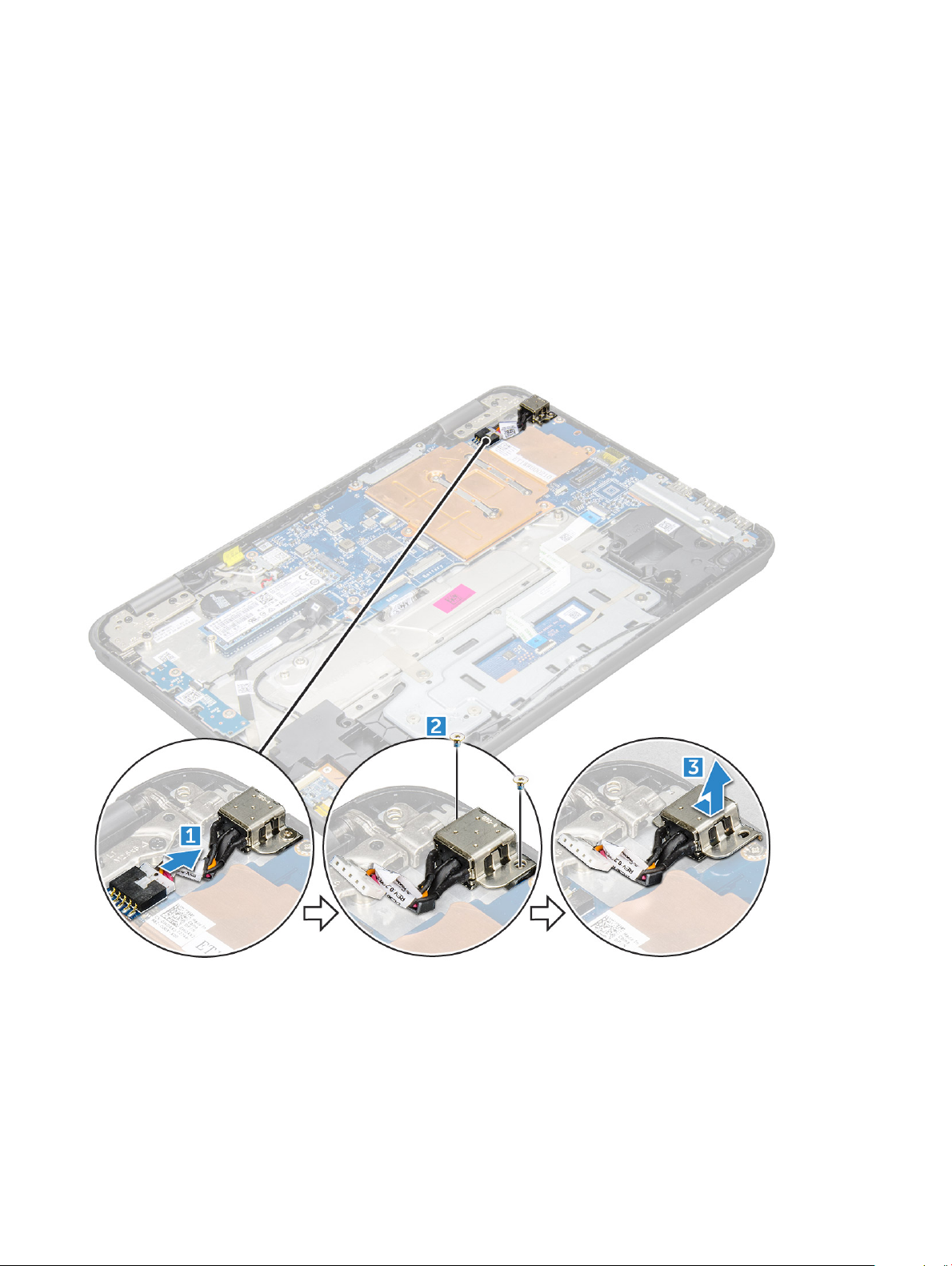
Removing power connector port..............................................................................................................................21
Installing power connector port................................................................................................................................21
Coin cell battery............................................................................................................................................................... 22
Removing coin cell battery........................................................................................................................................22
Installing coin cell battery..........................................................................................................................................23
Speaker............................................................................................................................................................................. 23
Removing speaker......................................................................................................................................................23
Installing speakers...................................................................................................................................................... 24
Touchpad panel................................................................................................................................................................ 24
Removing touchpad...................................................................................................................................................24
Installing touchpad..................................................................................................................................................... 27
Display assembly...............................................................................................................................................................27
Contents
3
Page 4

Removing display assembly.......................................................................................................................................27
Installing display assembly.........................................................................................................................................30
Display back cover...........................................................................................................................................................30
Removing display back cover....................................................................................................................................31
Installing display back cover......................................................................................................................................32
System board....................................................................................................................................................................32
Removing system board............................................................................................................................................32
Installing system board.............................................................................................................................................. 36
World facing camera........................................................................................................................................................ 37
Removing world facing camera................................................................................................................................ 37
Installing world facing camera.................................................................................................................................. 38
Palm rest...........................................................................................................................................................................38
Replacing the palm rest.............................................................................................................................................38
3 Technology and components....................................................................................................................... 40
Power adapter..................................................................................................................................................................40
Processors........................................................................................................................................................................ 40
Identifying processors in Windows 10..................................................................................................................... 40
Verifying the processor usage in Task Manager..................................................................................................... 41
Verifying the processor usage in Resource Monitor...............................................................................................41
Chipsets............................................................................................................................................................................. 41
Identifying the chipset in Device Manager on Windows 10...................................................................................41
Intel HD Graphics .......................................................................................................................................................41
Display options.................................................................................................................................................................. 41
Identifying the display adapter..................................................................................................................................41
Changing the screen resolution................................................................................................................................ 41
Adjusting brightness in Windows 10........................................................................................................................ 42
Connecting to external display devices...................................................................................................................42
Memory features..............................................................................................................................................................42
Verifying system memory in Windows 10................................................................................................................42
Verifying system memory in system setup (BIOS)................................................................................................ 42
Testing memory using ePSA.....................................................................................................................................42
Graphic options................................................................................................................................................................ 43
Hard drive options............................................................................................................................................................43
Identifying the hard drive in Windows 10................................................................................................................43
Identifying the hard drive in the BIOS..................................................................................................................... 43
USB features.................................................................................................................................................................... 44
USB 3.0/USB 3.1 Gen 1 (SuperSpeed USB)...........................................................................................................44
Speed...........................................................................................................................................................................44
Applications.................................................................................................................................................................45
Compatibility...............................................................................................................................................................45
HDMI 1.4............................................................................................................................................................................46
HDMI 1.4 Features......................................................................................................................................................46
Advantages of HDMI.................................................................................................................................................46
Realtek ALC3246............................................................................................................................................................. 46
Camera features...............................................................................................................................................................46
Starting the camera...................................................................................................................................................47
Contents
4
Page 5

Starting the camera application............................................................................................................................... 47
4 BIOS Overview............................................................................................................................................ 49
Boot menu........................................................................................................................................................................ 49
5 System setup options..................................................................................................................................50
Navigation keys................................................................................................................................................................50
System Setup overview.................................................................................................................................................. 50
Accessing System Setup................................................................................................................................................. 51
General screen options.....................................................................................................................................................51
System Conguration screen options........................................................................................................................... 52
Video screen options....................................................................................................................................................... 52
Security screen options...................................................................................................................................................53
Secure Boot screen options........................................................................................................................................... 54
Performance screen options.......................................................................................................................................... 55
Power management screen options..............................................................................................................................55
POST behavior screen options.......................................................................................................................................57
Wireless screen options...................................................................................................................................................57
Maintenance screen options...........................................................................................................................................57
System logs screen options............................................................................................................................................58
SupportAssist system resolution....................................................................................................................................58
Updating the BIOS ..........................................................................................................................................................58
System and setup password.......................................................................................................................................... 59
Assigning a system password and setup password...............................................................................................59
Deleting or changing an existing system and/or setup password....................................................................... 60
6 Technical specications................................................................................................................................61
System specications.......................................................................................................................................................61
Processor specications..................................................................................................................................................61
Memory specications.................................................................................................................................................... 62
Storage specications.....................................................................................................................................................62
Audio specications.........................................................................................................................................................62
Video specications.........................................................................................................................................................62
Camera specications..................................................................................................................................................... 63
Communication specications........................................................................................................................................63
Port and connector specications.................................................................................................................................63
Keyboard specications.................................................................................................................................................. 64
Touchpad specications..................................................................................................................................................64
Battery specications......................................................................................................................................................64
AC adapter specications...............................................................................................................................................64
Physical specications.....................................................................................................................................................65
Environmental specications..........................................................................................................................................65
7 Troubleshooting........................................................................................................................................... 66
Enhanced Pre-Boot System Assessment — ePSA diagnostics................................................................................66
Running the ePSA Diagnostics.................................................................................................................................66
Real Time Clock (RTC) reset....................................................................................................................................66
Contents
5
Page 6

8 Contacting Dell............................................................................................................................................68
6 Contents
Page 7

Working on your computer
Safety instructions
Use the following safety guidelines to protect your computer from potential damage and to ensure your personal safety. Unless otherwise
noted, each procedure included in this document assumes that the following conditions exist:
• You have read the safety information that shipped with your computer.
• A component can be replaced or, if purchased separately, installed by performing the removal procedure in the reverse order.
WARNING: Disconnect all power sources before opening the computer cover or panels. After you nish working inside the
computer, replace all covers, panels, and screws before connecting to the power source.
WARNING: Before working inside your computer, read the safety information that shipped with your computer. For additional
safety best practices information, see the Regulatory Compliance Homepage at www.dell.com/regulatory_compliance
CAUTION: Many repairs may only be done by a certied service technician. You should only perform troubleshooting and simple
repairs as authorized in your product documentation, or as directed by the online or telephone service and support team.
Damage due to servicing that is not authorized by Dell is not covered by your warranty. Read and follow the safety instructions
that came with the product.
1
CAUTION: To avoid electrostatic discharge, ground yourself by using a wrist grounding strap or by periodically touching an
unpainted metal surface that is grounded to ground yourself before you touch the computer to perform any disassembly tasks.
CAUTION: Handle components and cards with care. Do not touch the components or contacts on a card. Hold a card by its
edges or by its metal mounting bracket. Hold a component such as a processor by its edges, not by its pins.
CAUTION: When you disconnect a cable, pull on its connector or on its pull-tab, not on the cable itself. Some cables have
connectors with locking tabs; if you are disconnecting this type of cable, press in on the locking tabs before you disconnect the
cable. As you pull connectors apart, keep them evenly aligned to avoid bending any connector pins. Also, before you connect a
cable, ensure that both connectors are correctly oriented and aligned.
NOTE: The color of your computer and certain components may appear dierently than shown in this document.
Before working inside your computer
1 Ensure that your work surface is at and clean to prevent the computer cover from being scratched.
2 Turn o your computer.
3 Disconnect all network cables from the computer (if available).
CAUTION
computer.
4 Disconnect your computer and all attached devices from their electrical outlets.
5 Open the display.
6 Press and hold the power button for few seconds, to ground the system board.
CAUTION
8.
: If your computer has an RJ45 port, disconnect the network cable by rst unplugging the cable from your
: To guard against electrical shock unplug your computer from the electrical outlet before performing Step #
CAUTION: To avoid electrostatic discharge, ground yourself by using a wrist grounding strap or by periodically touching
an unpainted metal surface at the same time as touching a connector on the back of the computer.
7 Remove any installed ExpressCards or Smart Cards from the appropriate slots.
Working on your computer 7
Page 8

Turning o your — Windows
CAUTION: To avoid losing data, save and close all open les and exit all open programs before you turn o your computer .
Click or tap .
1
2 Click or tap and then click or tap Shut down.
NOTE: Ensure that the computer and all attached devices are turned o. If your computer and attached devices did not
automatically turn o when you shut down your operating system, press and hold the power button for about 6 seconds
to turn them o.
After working inside your computer
After you complete any replacement procedure, ensure that you connect any external devices, cards, and cables before turning on your
computer.
CAUTION: To avoid damage to the computer, use only the battery designed for this particular Dell computer. Do not use batteries
designed for other Dell computers.
1 Connect any external devices, such as a port replicator or media base, and replace any cards, such as an ExpressCard.
2 Connect any telephone or network cables to your computer.
CAUTION
computer.
3 Connect your computer and all attached devices to their electrical outlets.
4 Turn on your computer.
: To connect a network cable, rst plug the cable into the network device and then plug it into the
8
Working on your computer
Page 9

Removing and installing components
This section provides detailed information on how to remove or install the components from your computer.
Recommended tools
The procedures in this document require the following tools:
• Phillips #0 screwdriver
• Phillips #1 screwdriver
• Plastic scribe
NOTE: The #0 screw driver is for screws 0-1 and the #1 screw driver is for screws 2-4
microSD card
Removing microSD card
2
1 Follow the procedure in Before working inside your computer.
2 Press in on the microSD card to release it from the computer.
3 Remove the microSD card from the computer.
Installing microSD card
1 Slide the SD card into its slot until it clicks into place.
2 Install the microSD card.
3 Follow the procedure in After working inside your computer.
Base cover
Removing base cover
1 Follow the procedure in Before working inside your computer.
2 Remove the microSD card.
3 To remove the base cover:
a Loosen the M2.5x7 captive screws that secure the base cover to the computer [1, 2].
Removing and installing components 9
Page 10
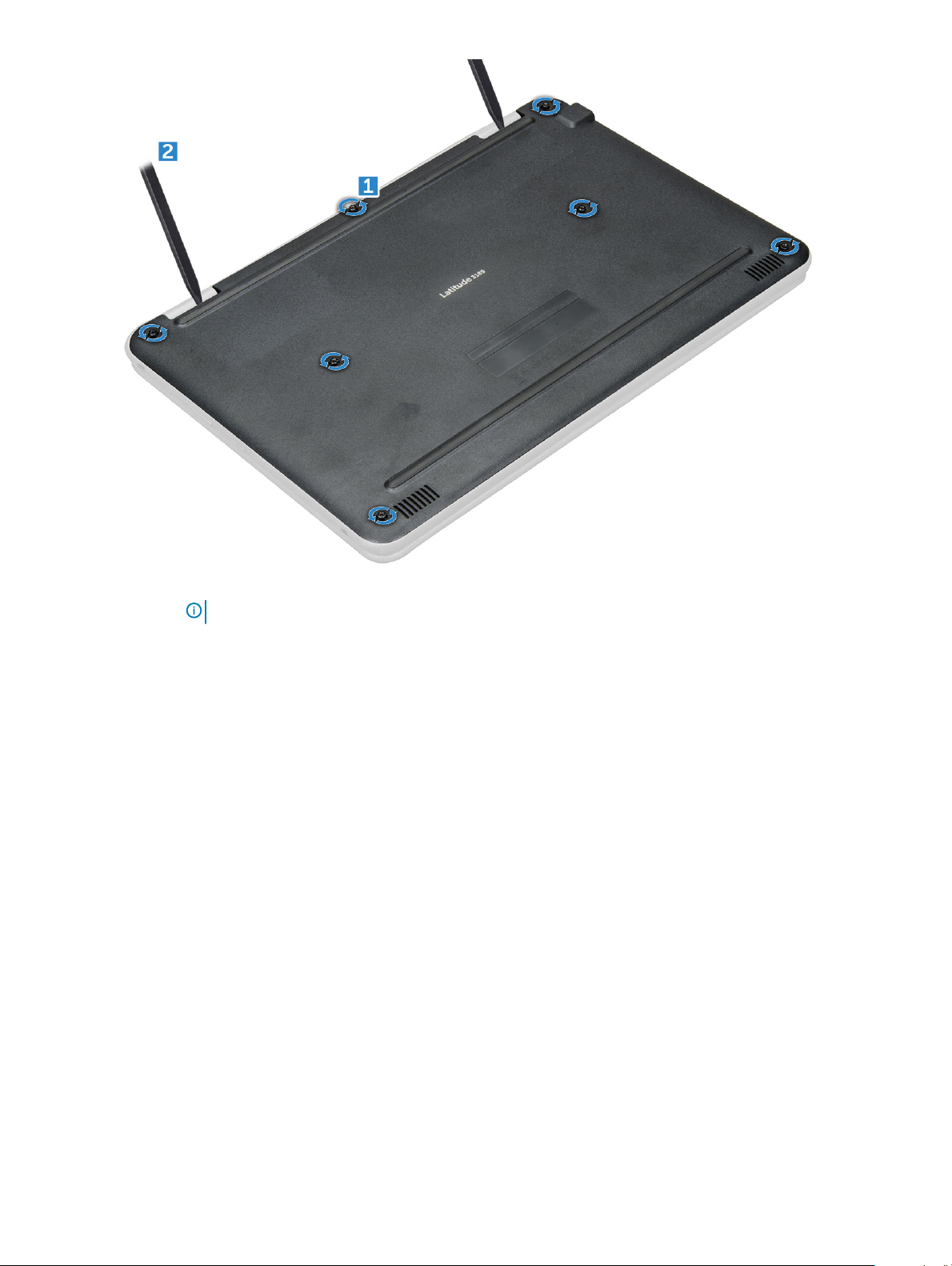
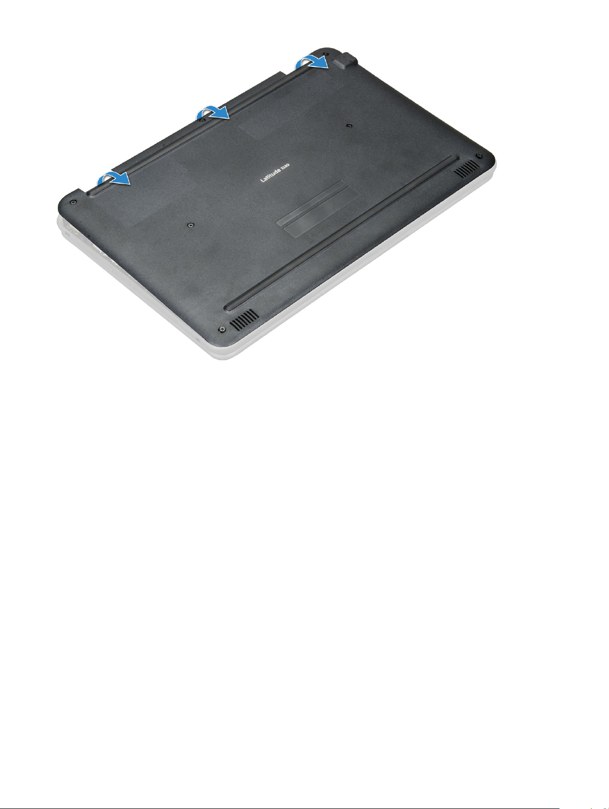
b Pry the base cover from the edge.
NOTE
: You may need a 3c plastic scribe to pry the base cover from the edge.
4 Lift the base cover away from the computer.
10
Removing and installing components
Page 11
Installing base cover
1 Toe in the base cover front edge into the system.
2 Press the edges of the cover until it clicks into place.
3 Replace the M2.5x7 screws to secure the base cover to the computer.
4 Install the microSD card
5 Follow the procedure in After working inside your computer.
Removing and installing components
11
Page 12

Battery
Lithium-ion battery precautions
CAUTION:
• Exercise caution when handling Lithium-ion batteries.
• Discharge the battery as much as possible before removing it from the system. This can be done by disconnecting the AC adapter
from the system to allow the battery to drain.
• Do not crush, drop, mutilate, or penetrate the battery with foreign objects.
• Do not expose the battery to high temperatures, or disassemble battery packs and cells.
• Do not apply pressure to the surface of the battery.
• Do not bend the battery.
• Do not use tools of any kind to pry on or against the battery.
• If a battery gets stuck in a device as a result of swelling, do not try to free it as puncturing, bending, or crushing a Lithium-ion
battery can be dangerous. In such an instance, the entire system should be replaced. Contact https://www.dell.com/support for
assistance and further instructions.
• Always purchase genuine batteries from https://www.dell.com or authorized Dell partners and re-sellers.
Removing battery
1 Follow the procedure in Before working inside your computer.
2 Remove the:
a microSD card
b base cover
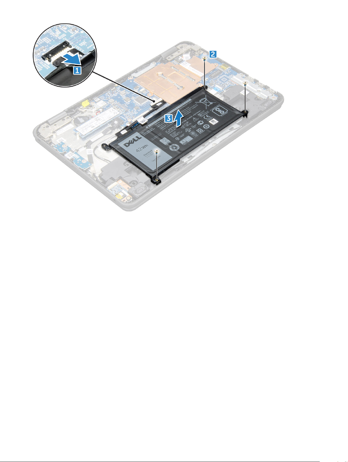
3 To remove the battery:
a Disconnect the battery cable from the connector on the system board [1].
b Remove the M2.0x3.0 screws that secure the battery to the computer [2].
c Lift the battery away from the computer [3].
12
Removing and installing components
Page 13
Installing battery
1 Insert the battery into the slot on the computer.
2 Connect the battery cable to the connector on the battery.
3 Replace the M2.0x3.0 screws to secure the battery to the computer.
4 Install the:
a base cover
b microSD card
5 Follow the procedure in After working inside your computer.
Keyboard
Removing keyboard
1 Follow the procedure in Before working inside your computer.
2 Remove the:
a microSD card
b base cover
c battery
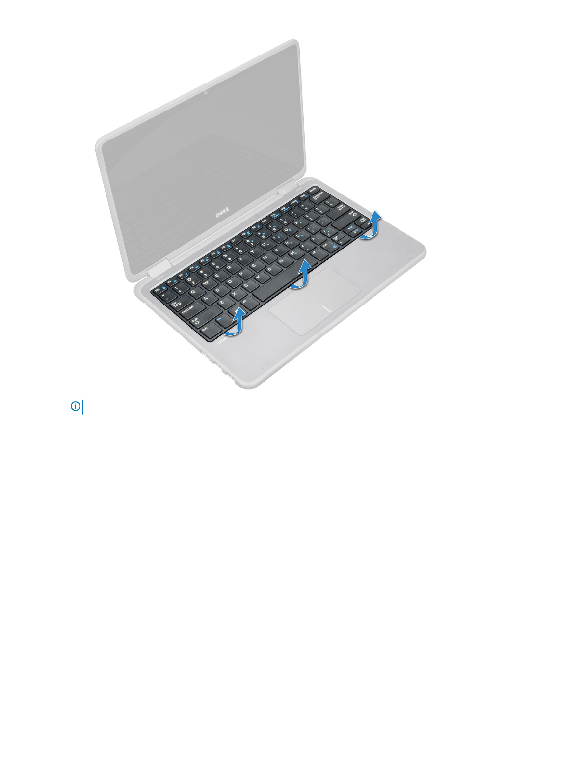
3 To remove keyboard:
a Disconnect the keyboard cable from the system board [1].
b Use the plastic scribe to the release the keyboard [2].
Removing and installing components
13
Page 14
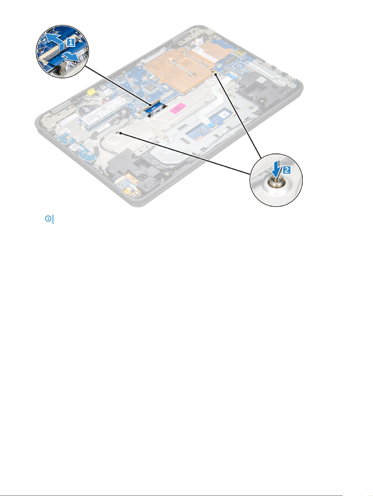
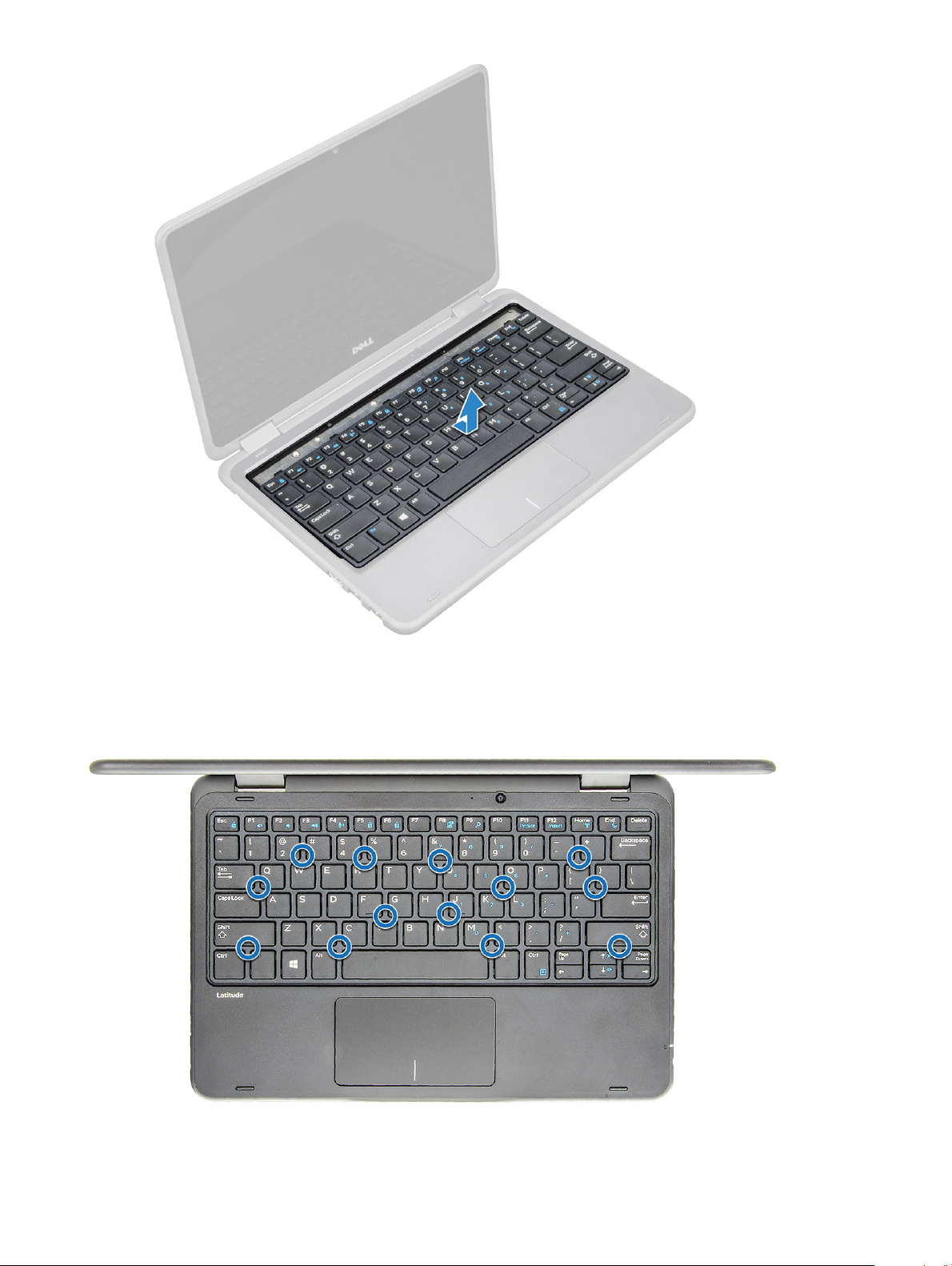
NOTE: The two release holes for the keyboard are indicated by the "KB" labeling.
4 Slide the keyboard outwards, away from the computer.
14
Removing and installing components
Page 15
NOTE: Carefully pull the keyboard connector through the gap in the palm rest.
5 Lift the keyboard away from the computer.
Removing and installing components
15
Page 16
Installing keyboard
1 Align the keyboard trim with the tabs on the computer, and press it until it clicks into place.
2 Connect the keyboard cable on the system board.
Removing and installing components
16
Page 17
3 Install the:
a battery
b base cover
c microSD card
4 Follow the procedure in After working inside your computer.
Solid State Drive (SSD)
Removing M.2 Solid State Drive (SSD)
1 Follow the procedure in Before working inside your computer.
2 Remove the:
a microSD card
b base cover
c battery
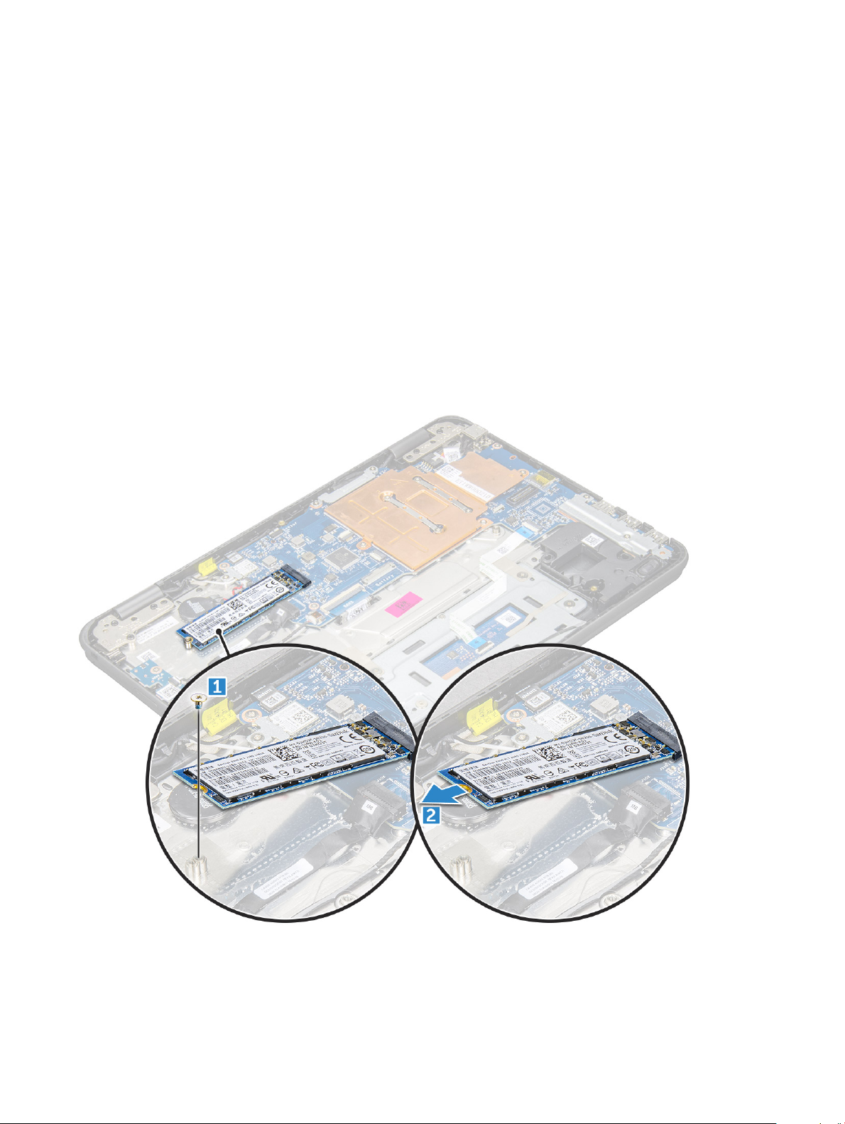
3 To remove the SSD:
a Remove the M2.0x3.0 screw that secures the SSD card [1].
b Slide and lift the SSD card from the system board [2].
Removing and installing components 17
Page 18

Installing M.2 Solid State Drive (SSD)
1 Align the notch on the SSD card with the tab on the SSD card connector and slide the card into the slot.
2 Align the screw hole on the SSD card with the screw hole on the system board.
3 Replace the screw that secures the SSD card to the system board.
4 Install the:
a battery
b base cover
c microSD card
5 Follow the procedure in After working inside your computer.
Power switch board
Removing power switch board
1 Follow the procedure in Before working inside your computer.
2 Remove the:
a microSD card
b base cover
c battery
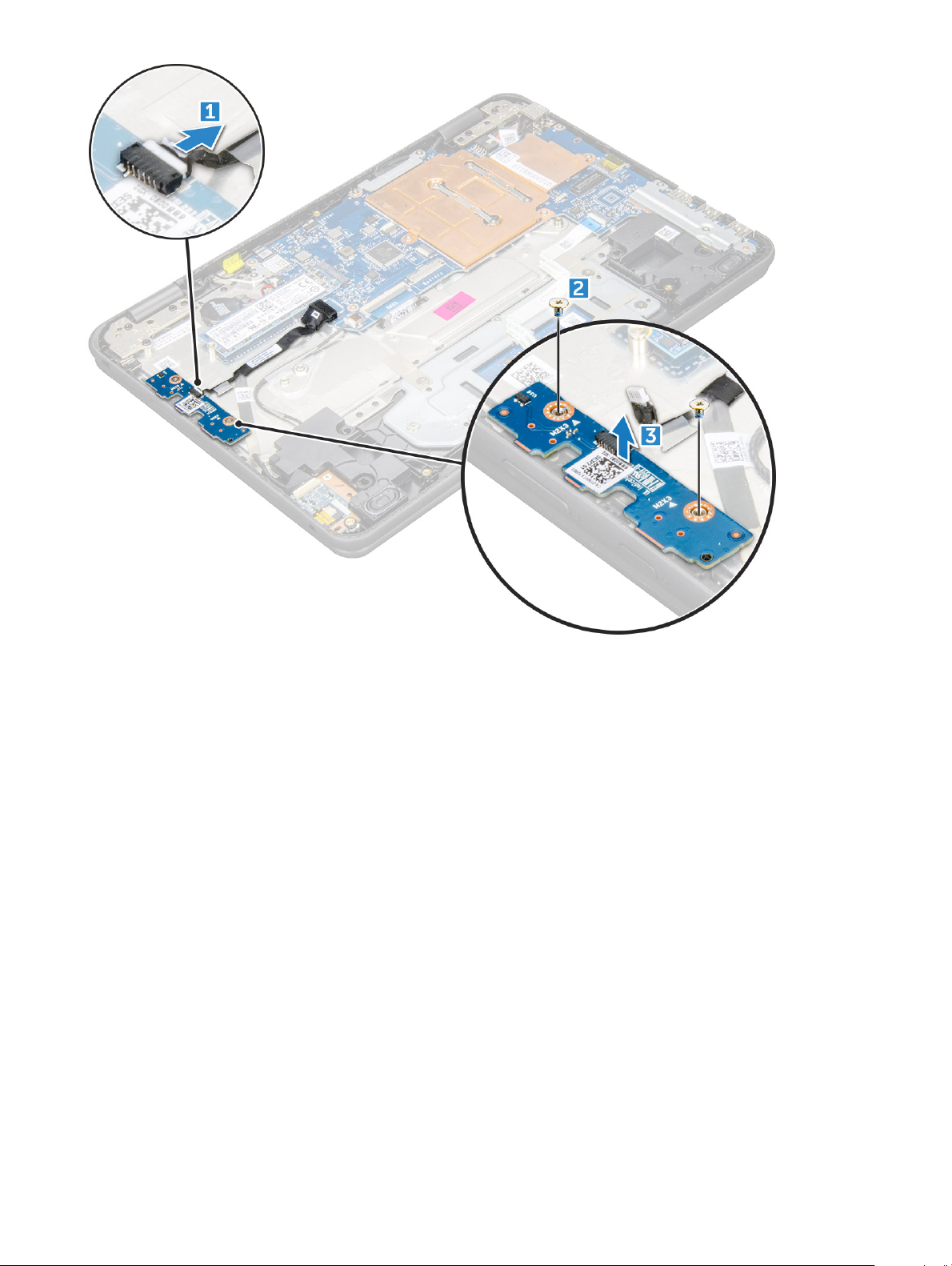
3 To remove the power switch:
a Disconnect the power switch cable from the power switch board [1].
b Remove the M.2.0x3.0 screws that secure the power switch board on the computer [2].
c Lift the power switch board away from the computer [3].
18
Removing and installing components
Page 19
Installing power switch board
1 Align the screw hole on the power switch board into the slot on the computer.
2 Replace the M2.0x3.0 screws that secure the power switch board to the computer.
3 Connect the power switch cable to the connector on the power switch board.
4 Install the:
a battery
b base cover
c microSD card
5 Follow the procedure in After working inside your computer.
Audio board
Removing audio board
1 Follow the procedure in Before working inside your computer.
2 Remove the:
a microSD card
b base cover
c battery
Removing and installing components
19
Page 20
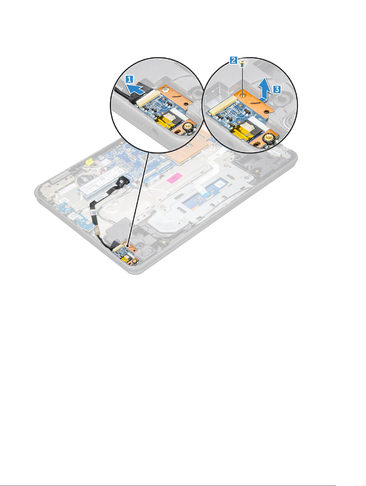
3 To remove the audio board:
a Disconnect the audio cable from the connector on the audio board [1].
b Remove the M.2.0x3.0 screw that secures the audio board on the computer [2].
c Lift the audio board away from the computer [3].
Installing audio board
1 Insert the audio board into the slot on the computer.
2 Replace the M2.0x3.0 screw that secure the audio board to the computer.
3 Connect the audio cable to the connector on the audio board.
4 Install the:
a battery
b base cover
c microSD card
5 Follow the procedure in After working inside your computer.
Removing and installing components
20
Page 21
Power connector port
Removing power connector port
1 Follow the procedure in Before working inside your computer.
2 Remove the:
a microSD card
b base cover
c battery
3 To remove the power connector port:
a Disconnect the power connector cable from the connector on the system board [1].
b Remove the M.2.0x3.0 screws that secure the power connector port on the computer [2].
c Slide and lift the power connector port away from the computer [3].
Installing power connector port
1 Insert the power connector port into the slot on the computer.
2 Replace the M2.0x3.0 screw that secures the power connector port to the computer.
3 Connect the power connector cable to the connector on the system board.
4 Install the:
Removing and installing components
21
Page 22

a battery
b base cover
c microSD card
5 Follow the procedure in After working inside your computer.
Coin cell battery
Removing coin cell battery
1 Follow the procedure in Before working inside your computer.
2 Remove the:
a microSD card
b base cover
c battery
3 To remove the coin cell battery:
a Disconnect the coin cell battery cable from the connector on the system board [1].
b Pry the coin cell battery to release it from the adhesive and lift it away from the computer [2].
22 Removing and installing components
Page 23

Installing coin cell battery
1 Place the coin cell battery into the slot on the computer.
2 Connect the coin cell battery cable to the connector on the system board.
3 Install the:
a battery
b base cover
c microSD card
4 Follow the procedure in After working inside your computer.
Speaker
Removing speaker
1 Follow the procedure in Before working inside your computer.
2 Remove the:
a microSD card
b base cover
c battery
3 To remove the speaker:
a Disconnect the speaker cable from the connector on the system board [1].
b Remove the adhesive tape that secures the speaker cable on the computer [2].
c Unroute the speaker cable from the routing channel [3].
4 Remove the speaker from the computer.
Removing and installing components
23
Page 24

Installing speakers
1 Place the speakers into the slots on the computer.
2 Route the speaker cable through the retention clips through routing channel.
3 Ax the adhesive tape to secure the speaker cable on the computer.
4 Connect the speaker cable to the connector on the system board.
5 Install the:
a battery
b base cover
c microSD card
6 Follow the procedure in After working inside your computer.
Touchpad panel
Removing touchpad
1 Follow the procedure in Before working inside your computer.
2 Remove the:
a microSD card
b base cover
c battery
d speaker
3 To remove the touchpad cable:
a Lift the latch, and disconnect the touchpad cable from the computer [1].
b Remove the touchpad cable [2].
Removing and installing components
24
Page 25

4 Remove the screws (M2.0x3.0, M.2.0x2.0) that secure the metal bracket to the touchpad on the computer.
NOTE
: Remove the adhesive tape that secures the speaker cable on the metal bracket.
5 To remove metal bracket:
a Remove the adhesive tape [1, 2].
b Lift the metal bracket [3].
Removing and installing components
25
Page 26

6 Remove the touchpad from the computer.
26
Removing and installing components
Page 27

Installing touchpad
1 Place the touchpad into the slots on the computer.
2 Place the metal bracket, and ax the adhesive tape.
3 Replace the screws (M2.0x3.0, M.2.0x2.0) that secure the metal bracket on the computer.
NOTE: Ax the adhesive tape that secures the speaker cable on the metal bracket.
Connect the touchpad cable.
4
5 Ax the adhesive tape to secure the speaker cable on the computer.
6 Connect the speaker cable to the connector on the system board.
7 Install the:
a speaker
b battery
c base cover
d microSD card
8 Follow the procedure in After working inside your computer.
Display assembly
Removing display assembly
1 Follow the procedure in Before working inside your computer.
2 Remove the:
a microSD card
b base cover
c battery
3 To remove cables:
a Remove the screw M2.0x3.0 and lift the metal bracket that secures the WLAN card on the system board [1, 2].
b Disconnect the WLAN cables [3].
c Remove the screws M2.0x.30 and lift the metal bracket that secures the display cable on the computer [4, 5].
d Lift the latch, and disconnect the cable [6].
Removing and installing components
27
Page 28

4 Disconnect the sensor cable on the system board, and ip over the computer [1, 2]
28
Removing and installing components
Page 29

5 To remove the display assembly:
a Remove the display hinge screws M2.0xM5.0 that secure the display assembly to the computer [1].
b Lift the display assembly away from the computer [2].
Removing and installing components
29
Page 30

Installing display assembly
1 Place the display assembly to align with the screw holders on the computer.
2 Replace the screws that secure the display hinges to the palm-rest assembly.
3 Flip over the computer and connect the sensor cable on the system board.
4 Connect the display cable to the connector on the system board.
5 Place the metal bracket over the (display cable) connector, and tighten the M2.0x3.0 screws to secure the display cable to the
computer.
6 Connect the WLAN cables.
7 Place the metal bracket, and tighten the M2.0x3.0 screw to the WLAN cable on the system board.
8 Install the:
a battery
b base cover
c microSD card
9 Follow the procedure in After working inside your computer.
Display back cover
Removing and installing components
30
Page 31

Removing display back cover
1 Follow the procedure in Before working inside your computer.
2 Using the plastic scribe pry the edges of the display back cover.
3 Remove the display back cover away from the computer.
Removing and installing components
31
Page 32

Installing display back cover
1 Align the display back cover with the tabs on the computer, and press it until it clicks into place.
2 Follow the procedure in After working inside your computer.
System board
Removing system board
1 Follow the procedure in Before working inside your computer.
2 Remove the:
a microSD card
b base cover
c battery
d SSD card
3 Disconnect the following cables:
a sensor cable [1]
b world facing camera cable [2]
c coin cell battery cable [3]
d power board and audio cable [4]
e speaker cable [5]
f keyboard cable [6]
g touch pad cable [7]
h power connector cable [8]
Removing and installing components
32
Page 33

4 To remove metal bracket on the system board:
a Remove the screws on the metal bracket that secures the system board [1].
b Lift the metal bracket o the system board [2].
Removing and installing components
33
Page 34

5 To remove the metal bracket (WLAN and display cable):
a Remove the M2.0x3.0 screw and lift the metal bracket that secures the WLAN card on the system board [1, 2]
b Disconnect the WLAN cables [3].
c Remove the screws M2.0x.30 and lift the metal bracket that secures the display cable on the computer [4, 5]
d Lift the latch, and disconnect the cable [6]
34
Removing and installing components
Page 35

6 To remove the system board:
a Remove the screws that secure the system board on the palm rest assembly [1].
b Lift the system board o the palm- rest assembly [2].
Removing and installing components
35
Page 36

Installing system board
1 Align the system board with the screw holders on the palm rest assembly.
2 Replace the M2.0x3.0 screws to secure the system board to the palm rest assembly.
3 Connect the display cable to the connector on the system board.
4 Place the metal bracket over the connector, and tighten the M2.0x3.0 screws to secure the display cable to the system board.
5 Connect the WLAN cables.
6 Place the metal bracket on the WLAN card, and tighten the M2.0x3.0 screw to secure the WLAN cable on the WLAN card.
7 Place the metal bracket on the system board and tighten M2.0x3.0 screws to secure on the system board.
8 Connect the following cables:
a power connector cable
b touchpad cable
c keyboard cable
d speaker cable
e audio cable
f coin cell battery cable
g camera cable
9 Install the:
a SSD card
b battery
c base cover
d microSD card
10 Follow the procedure in After working inside your computer.
Removing and installing components
36
Page 37

World facing camera
Removing world facing camera
1 Follow the procedure in Before working inside your computer.
2 Remove the:
a microSD card
b base cover
c battery
d keyboard
e SSD card
f power switch board
g audio
h power connector
i coin cell battery
j speaker
k touchpad
l system board
3 To remove the world facing camera:
a Remove the adhesive tape that secures the camera [1].
b Lift the camera away from the palm rest assembly [2].
Removing and installing components
37
Page 38

Installing world facing camera
1 Insert the camera into the slot on the computer.
2 Ax the tape to secure the camera on the palm rest assembly.
3 Install the:
a system board
b touchpad
c speaker
d coin cell battery
e power connector
f audio
g power switch board
h SSD card
i keyboard
j battery
k base cover
l microSD card
4 Follow the procedure in After working inside your computer.
Palm rest
Replacing the palm rest
1 Follow the procedure in Before working inside your computer.
2 Remove the:
a microSD card
b base cover
c battery
d keyboard
e SSD card
f power switch board
g audio
h power connector
i coin cell battery
j speaker
k touchpad
l display assembly
m system board
n world facing camera
: The component you are left with is the palm rest.
NOTE
38 Removing and installing components
Page 39

3 Install the following components on the new palm rest:
a world facing camera
b system board
c display assembly
d touchpad
e speaker
f coin cell battery
g power connector
h audio
i power switch board
j SSD card
k keyboard
l battery
m base cover
n microSD card
4 Follow the procedure in After working inside your computer.
Removing and installing components
39
Page 40

Technology and components
This chapter details the technology and components available in the systems.
Topics:
• Power adapter
• Processors
• Chipsets
• Display options
• Memory features
• Graphic options
• Hard drive options
• USB features
• HDMI 1.4
• Realtek ALC3246
• Camera features
3
Power adapter
This laptop is shipped with 65 W power adapter.
WARNING
pull rmly but gently to avoid damaging the cable.
WARNING: The power adapter works with electrical outlets worldwide. However, power connectors and power strips vary
among countries. Using an incompatible cable or improperly connecting the cable to the power strip or electrical outlet may
cause re or equipment damage.
: When you disconnect the power adapter cable from the laptop, grasp the connector, not the cable itself, and then
Processors
This laptop is shipped with the following processors:
• Intel Celeron Processor N3350 (6 W, 2 M cache, up to 2.4 GHz)
• Intel Pentium Processor N4200 (6 W, 2 M cache, up to 2.5 GHz)
: The clock speed and performance varies depending on the workload and other variables.
NOTE
Identifying processors in Windows 10
1 Tap Search the Web and Windows.
2 Type Device Manager.
3 Tap Processor.
40 Technology and components
Page 41

Verifying the processor usage in Task Manager
1 Right-click the laptop.
2 Select Start Task Manager.
The Windows Task Manager window is displayed.
3 Click the Performance tab in the Windows Task Manager window.
Verifying the processor usage in Resource Monitor
1 Right-click the laptop.
2 Select Start Task Manager.
The Windows Task Manager window is displayed.
3 Click the Performance tab in the Windows Task Manager window.
The processor performance details are displayed.
4 Click Open Resource Monitor.
Chipsets
All laptops or notebook communicate with the CPU through the chipset. This laptop is shipped with the Intel 100 Series chipset.
Identifying the chipset in Device Manager on Windows 10
1 Click All Settings on the Windows 10 Charms Bar.
2 From the Control Panel, select Device Manager.
3 Expand System Devices and search for the chipset.
Intel HD Graphics
This computer is shipped with the Intel HD Graphics graphics chipset.
Display options
Identifying the display adapter
1 Start the Search Charm and select Settings.
2 Type Device Manager in the search box, and tap Device Manager from the left pane.
3 Expand Display adapters.
Changing the screen resolution
1 Right-click on the laptop and select Display Settings.
2 Tap or click Advanced display settings.
Technology and components
41
Page 42

3 Select the required resolution from the drop-down list and tap Apply.
Adjusting brightness in Windows 10
To enable or disable automatic screen brightness adjustment:
1 Right-click All Settings → System → Display.
2 Use the Adjust my screen brightness automatically slider to enable or disable automatic-brightness adjustment.
NOTE: You can also use the Brightness level slider to adjust the brightness manually.
Connecting to external display devices
Follow these steps to connect your computer to an external display device:
1 Ensure that the projector is turned on and plug the projector cable into a video port on your computer.
2 Press the Windows logo+P key.
3 Select one of the following modes:
• PC screen only
• Duplicate
• Extend
• Second Screen only
Memory features
This laptop supports a maximum memory of 4 GB LPDDR3 1600 Mhz.
Verifying system memory in Windows 10
1 Tap the Windows button and select All Settings > System.
2 Under System, tap About.
Verifying system memory in system setup (BIOS)
1 Turn on or restart your laptop.
2 Perform one of the following actions after the Dell logo is displayed:
• With keyboard — Tap F2 until the Entering BIOS setup message appears. To enter the Boot selection menu, tap F12.
• Without keyboard — When the F12 boot selection menu is displayed, press the Volume Down button to enter BIOS setup. To
enter the Boot selection menu, press the Volume Up button.
3 On the left pane, select Settings > General > System Information,
The memory information is displayed on the right pane.
Testing memory using ePSA
1 Turn on or restart your laptop.
2 Perform one of the following actions after the Dell logo is displayed:
• With keyboard — Press F2.
Technology and components
42
Page 43

• Without keyboard — Press and hold the Volume Up button when the Dell logo is displayed on the screen. When the F12 boot
selection menu is displayed, select Diagnostics from the boot menu, and press Enter.
The PreBoot System Assessment (PSA) starts on your laptop.
NOTE: If you wait too long and the operating system logo appears, continue to wait until you see the desktop. Turn o
the laptop and try again.
Graphic options
This laptop is shipped with the following graphics chipset options:
• Pentium Intel HD Graphics 500
• Celeron Intel HD Graphics 505
Hard drive options
This laptop supports :
• M.2 128GB SATA Class 20 Solid State Drive
• M.2 256GB SATA Class 20 Solid State Drive
Identifying the hard drive in Windows 10
1 Click All Settings on the Windows 10 Charms Bar.
2 Click Control Panel, select Device Manager, and expand Disk drives.
The hard drive is listed under Disk drives.
Identifying the hard drive in the BIOS
1 Turn on or restart your laptop.
2 When the Dell logo appears, perform one of the following actions to enter the BIOS setup program:
• With keyboard — Tap F2 until the Entering BIOS setup message appears. To enter the Boot selection menu, tap F12.
• Without keyboard — When the F12 boot selection menu is displayed, press the Volume Down button to enter BIOS setup. To
enter the Boot selection menu, press the Volume Up button.
The hard drive is listed under the System Information under the General group.
Technology and components
43
Page 44

USB features
Universal Serial Bus, or USB, was introduced in 1996. It dramatically simplied the connection between host computers and peripheral
devices like mice, keyboards, external drivers, and printers.
Let's take a quick look on the USB evolution referencing to the table below.
Table 1. USB evolution
Type Data Transfer Rate Category Introduction Year
USB 2.0 480 Mbps High Speed 2000
USB 3.0/USB 3.1 Gen 1 5 Gbps Super Speed 2010
USB 3.1 Gen 2 10 Gbps Super Speed 2013
USB 3.0/USB 3.1 Gen 1 (SuperSpeed USB)
For years, the USB 2.0 has been rmly entrenched as the de facto interface standard in the PC world with about 6 billion devices sold, and
yet the need for more speed grows by ever faster computing hardware and ever greater bandwidth demands. The USB 3.0/USB 3.1 Gen 1
nally has the answer to the consumers' demands with a theoretically 10 times faster than its predecessor. In a nutshell, USB 3.1 Gen 1
features are as follows:
• Higher transfer rates (up to 5 Gbps)
• Increased maximum bus power and increased device current draw to better accommodate power-hungry devices
• New power management features
• Full-duplex data transfers and support for new transfer types
• Backward USB 2.0 compatibility
• New connectors and cable
The topics below cover some of the most commonly asked questions regarding USB 3.0/USB 3.1 Gen 1.
Speed
Currently, there are 3 speed modes dened by the latest USB 3.0/USB 3.1 Gen 1 specication. They are Super-Speed, Hi-Speed and FullSpeed. The new SuperSpeed mode has a transfer rate of 4.8Gbps. While the specication retains Hi-Speed, and Full-Speed USB mode,
commonly known as USB 2.0 and 1.1 respectively, the slower modes still operate at 480Mbps and 12Mbps respectively and are kept to
maintain backward compatibility.
USB 3.0/USB 3.1 Gen 1 achieves the much higher performance by the technical changes below:
• An additional physical bus that is added in parallel with the existing USB 2.0 bus (refer to the picture below).
• USB 2.0 previously had four wires (power, ground, and a pair for dierential data); USB 3.0/USB 3.1 Gen 1 adds four more for two pairs
of dierential signals (receive and transmit) for a combined total of eight connections in the connectors and cabling.
• USB 3.0/USB 3.1 Gen 1 utilizes the bidirectional data interface, rather than USB 2.0's half-duplex arrangement. This gives a 10-fold
increase in theoretical bandwidth.
Technology and components
44
Page 45

With today's ever increasing demands placed on data transfers with high-denition video content, terabyte storage devices, high megapixel
count digital cameras etc., USB 2.0 may not be fast enough. Furthermore, no USB 2.0 connection could ever come close to the 480Mbps
theoretical maximum throughput, making data transfer at around 320Mbps (40MB/s) — the actual real-world maximum. Similarly, USB
3.0/USB 3.1 Gen 1 connections will never achieve 4.8Gbps. We will likely see a real-world maximum rate of 400MB/s with overheads. At this
speed, USB 3.0/USB 3.1 Gen 1 is a 10x improvement over USB 2.0.
Applications
USB 3.0/USB 3.1 Gen 1 opens up the laneways and provides more headroom for devices to deliver a better overall experience. Where USB
video was barely tolerable previously (both from a maximum resolution, latency, and video compression perspective), it's easy to imagine
that with 5-10 times the bandwidth available, USB video solutions should work that much better. Single-link DVI requires almost 2Gbps
throughput. Where 480Mbps was limiting, 5Gbps is more than promising. With its promised 4.8Gbps speed, the standard will nd its way
into some products that previously weren't USB territory, like external RAID storage systems.
Listed below are some of the available SuperSpeed USB 3.0/USB 3.1 Gen 1 products:
• External Desktop USB 3.0/USB 3.1 Gen 1 Hard Drives
• Portable USB 3.0/USB 3.1 Gen 1 Hard Drives
• USB 3.0/USB 3.1 Gen 1 Drive Docks & Adapters
• USB 3.0/USB 3.1 Gen 1 Flash Drives & Readers
• USB 3.0/USB 3.1 Gen 1 Solid-state Drives
• USB 3.0/USB 3.1 Gen 1 RAIDs
• Optical Media Drives
• Multimedia Devices
• Networking
• USB 3.0/USB 3.1 Gen 1 Adapter Cards & Hubs
Compatibility
The good news is that USB 3.0/USB 3.1 Gen 1 has been carefully planned from the start to peacefully co-exist with USB 2.0. First of all,
while USB 3.0/USB 3.1 Gen 1 species new physical connections and thus new cables to take advantage of the higher speed capability of
the new protocol, the connector itself remains the same rectangular shape with the four USB 2.0 contacts in the exact same location as
before. Five new connections to carry receive and transmitted data independently are present on USB 3.0/USB 3.1 Gen 1 cables and only
come into contact when connected to a proper SuperSpeed USB connection.
Windows 8/10 will be bringing native support for USB 3.1 Gen 1 controllers. This is in contrast to previous versions of Windows, which
continue to require separate drivers for USB 3.0/USB 3.1 Gen 1 controllers.
Technology and components
45
Page 46

Microsoft announced that Windows 7 would have USB 3.1 Gen 1 support, perhaps not on its immediate release, but in a subsequent Service
Pack or update. It is not out of the question to think that following a successful release of USB 3.0/USB 3.1 Gen 1 support in Windows 7,
SuperSpeed support would trickle down to Vista. Microsoft has conrmed this by stating that most of their partners share the opinion that
Vista should also support USB 3.0/USB 3.1 Gen 1.
HDMI 1.4
This topic explains the HDMI 1.4 and its features along with the advantages.
HDMI (High-Denition Multimedia Interface) is an industry-supported, uncompressed, all-digital audio/video interface. HDMI provides an
interface between any compatible digital audio/video source, such as a DVD player, or A/V receiver and a compatible digital audio and/or
video monitor, such as a digital TV (DTV). The intended applications for HDMI TVs, and DVD players. The primary advantage is cable
reduction and content protection provisions. HDMI supports standard, enhanced, or high-denition video, plus multichannel digital audio on
a single cable.
NOTE: The HDMI 1.4 will provide 5.1 channel audio support.
HDMI 1.4 Features
• HDMI Ethernet Channel - Adds high-speed networking to an HDMI link, allowing users to take full advantage of their IP-enabled
devices without a separate Ethernet cable
• Audio Return Channel - Allows an HDMI-connected TV with a built-in tuner to send audio data "upstream" to a surround audio system,
eliminating the need for a separate audio cable
• 3D - Denes input/output protocols for major 3D video formats, paving the way for true 3D gaming and 3D home theater applications
• Content Type - Real-time signaling of content types between display and source devices, enabling a TV to optimize picture settings
based on content type
• Additional Color Spaces - Adds support for additional color models used in digital photography and computer graphics
• 4K Support - Enables video resolutions far beyond 1080p, supporting next-generation displays that will rival the Digital Cinema systems
used in many commercial movie theaters
• HDMI Micro Connector - A new, smaller connector for phones and other portable devices, supporting video resolutions up to 1080p
• Automotive Connection System - New cables and connectors for automotive video systems, designed to meet the unique demands of
the motoring environment while delivering true HD quality
Advantages of HDMI
• Quality HDMI transfers uncompressed digital audio and video for the highest, crispest image quality.
• Low -cost HDMI provides the quality and functionality of a digital interface while also supporting uncompressed video formats in a
simple, cost-eective manner
• Audio HDMI supports multiple audio formats from standard stereo to multichannel surround sound
• HDMI combines video and multichannel audio into a single cable, eliminating the cost, complexity, and confusion of multiple cables
currently used in A/V systems
• HDMI supports communication between the video source (such as a DVD player) and the DTV, enabling new functionality
Realtek ALC3246
This laptop is shipped with integrated Realtek ALC3246 controller High Denition audio codec designed for Windows desktops and laptops.
Camera features
This laptop is shipped with front-facing camera and rear facing camera with the image resolution of 1280 x 720 (maximum).
Technology and components
46
Page 47

Starting the camera
To start the camera, open an application that uses the camera. For instance, if you tap the Dell webcam central software or the Skype
software that is shipped with the laptop, the camera turns on. Similarly, if you are chatting on the internet and the application requests to
access the webcam, the webcam turns on.
Starting the camera application
1 Tap or click the Windows button and select All apps.
2 Select Camera from the apps list.
3 If the Camera App is not available in the apps list, search for it.
Technology and components
47
Page 48

48 Technology and components
Page 49

4
BIOS Overview
Boot menu
Press <F12> when the Dell™ logo appears to initiate a one-time boot menu with a list of the valid boot devices for the system. Diagnostics
and BIOS Setup options are also included in this menu. The devices listed on the boot menu depend on the bootable devices in the system.
This menu is useful when you are attempting to boot to a particular device or to bring up the diagnostics for the system. Using the boot
menu does not make any changes to the boot order stored in the BIOS.
The options are:
• Legacy Boot:
– Internal HDD
– Onboard NIC
• UEFI Boot:
– Windows Boot Manager
• Other Options:
– BIOS Setup
– BIOS Flash Update
– Diagnostics
– Change Boot Mode Settings
BIOS Overview 49
Page 50

System setup options
NOTE: Depending on the computer and its installed devices, the items listed in this section may or may not appear.
Topics:
• Navigation keys
• System Setup overview
• Accessing System Setup
• General screen options
• System Conguration screen options
• Video screen options
• Security screen options
• Secure Boot screen options
• Performance screen options
• Power management screen options
• POST behavior screen options
• Wireless screen options
• Maintenance screen options
• System logs screen options
• SupportAssist system resolution
• Updating the BIOS
• System and setup password
5
Navigation keys
NOTE
: For most of the System Setup options, changes that you make are recorded but do not take eect until you restart the
system.
Keys Navigation
Up arrow Moves to the previous eld.
Down arrow Moves to the next eld.
Enter Selects a value in the selected eld (if applicable) or follow the link in the eld.
Spacebar Expands or collapses a drop‐down list, if applicable.
Tab Moves to the next focus area.
NOTE: For the standard graphics browser only.
Esc Moves to the previous page until you view the main screen. Pressing Esc in the main screen displays a message
that prompts you to save any unsaved changes and restarts the system.
F1 Displays the System Setup help le.
System Setup overview
System Setup allows you to:
50 System setup options
Page 51

• Change the system conguration information after you add, change, or remove any hardware in your computer.
• Set or change a user-selectable option such as the user password.
• Read the current amount of memory or set the type of hard drive installed.
Before you use System Setup, it is recommended that you write down the System Setup screen information for future reference.
CAUTION: Unless you are an expert computer user, do not change the settings for this program. Certain changes can cause your
computer to work incorrectly.
Accessing System Setup
1 Turn on (or restart) your computer.
2 After the white Dell logo appears, press F2 immediately.
The System Setup page is displayed.
NOTE: If you wait too long and the operating system logo appears, wait until you see the desktop. Then, shut down or
restart your computer and try again.
NOTE: After the Dell logo appears, you can also press F12 and then select BIOS setup.
General screen options
This section lists the primary hardware features of your computer.
Option
System Information This section lists the primary hardware features of your computer.
Battery Information Displays the battery status health and whether the AC adapter is installed.
Boot Sequence Allows you to change the order in which the computer attempts to nd an operating system.
Advanced Boot
Options
UEFI boot path
security
Description
• System Information: Displays BIOS Version, Service Tag, Asset Tag, Ownership Tag, Ownership Date,
Manufacture Date, Express Service Code, the Signed Firmware update—enabled by default
• Memory Information: Primary Hard Drive, SATA, Displays Memory Installed, Memory Available, Memory Speed,
Memory Channels Mode, Memory Technology
• Processor Information: Displays Processor Type, Core Count, Processor ID, Current Clock Speed, Minimum
Clock Speed, Maximum Clock Speed, Processor L2 Cache, HT Capable, and 64-Bit Technology
• Device Information: Passthrough MAC address, Video Controller, Video BIOS Version, Video Memory, Panel
Type, Native Resolution, Audio Controller, Wi-Fi Device, Bluetooth Device
• Windows Boot Manager ( Default)
• Boot List Option
– Legacy
– UEFI (System Default)
This option allows you the legacy option ROMs to load. By default, the Enable Legacy Option ROMs is disabled.
Enable Attempt Legacy Boot is enabled by default.
• Always, except internal HDD ( Default)
• Always
• Never
Date/Time Allows you to change the date and time.
System setup options 51
Page 52

System Conguration screen options
Option Description
Drives Allows you to congure the SATA drives on board.
• SATA-0 enabled by default
• eMMC (System Default)
USB Conguration
USB PowerShare This eld congures the USB PowerShare feature behavior. This option allows you to charge external devices using
Audio This eld enables or disables the integrated audio controller. By default, the Enable Audio option is selected. The
Debug Memory
Frequency
Conguration
This is an optional feature.
This eld congures the integrated USB controller. If Boot Support is enabled, the system is allowed to boot any
type of USB Mass Storage Devices—HDD, memory key, oppy.
If USB port is enabled, device attached to this port is enabled and available for OS.
If USB port is disabled, the OS cannot see any device attached to this port.
The options are:
• Enable Boot Support—enabled by default
• Enable External USB Port—enabled by default
NOTE: USB keyboard and mouse always work in the BIOS setup irrespective of these settings.
the stored system battery power through the USB PowerShare port. This option is disabled by default.
options are:
• Enable Microphone—by default enable
• Enable Internal Speaker—(default enable)
Allows you to enable or disable the following devices:
• Memory Frequency 1866
• Memory Frequency 1600 (default enable)
Miscellaneous
Devices
Allows you to enable or disable the following devices:
• Front-Facing Webcam (default enable)
• World-Facing Camera (default enable)
• Secure Digital (SD) card—enabled
• Secure Digital (SD) card boot
• Secure Digital (SD) card read-only-mode
Video screen options
Option
LCD Brightness Allows you to set the display brightness depending up on the power source—On Battery and On AC. The LCD
NOTE: The video setting is visible only when a video card is installed into the system.
52 System setup options
Description
brightness is independent for battery and AC adapter. It can be set using the slider.
Page 53

Security screen options
Option Description
Admin Password Allows you to set, change, or delete the administrator (admin) password.
NOTE: You must set the admin password before you set the system or hard drive password. Deleting the
admin password automatically deletes the system password and the hard drive password.
NOTE: Successful password changes take eect immediately.
Default setting: Not set
System Password Allows you to set, change, or delete the system password.
NOTE: Successful password changes take eect immediately.
Default setting: Not set
Internal HDD-0
Password
Strong Password Allows you to enforce the option to always set strong passwords.
Password
Conguration
Password Bypass Allows you to enable or disable the permission to bypass the System and the Internal HDD password, when they
Password Change Allows you to enable the disable permission to the System and Hard Drive passwords when the admin password is
Allows you to set, change, or delete the administrator password.
NOTE: Successful password changes take eect immediately.
Default setting: Not set
Default Setting: Enable Strong Password is not selected.
NOTE: If Strong Password is enabled, the Admin and System passwords must contain at least one
uppercase character, one lowercase character and be at least eight characters long.
Allows you to specify the minimum and max password lengths of the Administrator and System passwords.
• min-4—by default, if you want to change you can increase the number.
• max-32—you can decrease the number.
are set. The options are:
• Disabled —enabled by default
• Reboot bypass
set.
Default setting: Allow Non-Admin Password Changes is selected.
Non-Admin Setup
Changes
UEFI Capsule
Firmware Updates
TPM 2.0 Security Allows you to enable the Trusted Platform Module (TPM) during POST. The options are:
Allows you to determine whether changes to the setup options are allowed when an Administrator Password is set.
If disabled, the setup options are locked by the admin password.
Option "allow wireless switch changes" is not selected by default.
Allows you to enable or disable. This option controls whether this system allows BIOS updated via UEFI capsule
update packages. The options are:
• Enable UEFI Capsule Firmware—enabled by default
System setup options 53
Page 54

Option Description
• TPM On—enabled by default
• Clear
• PPI Bypass for Enable Commands—enabled by default
• PPI Bypass for Disabled Commands
• Attestation enable—enabled by default
• Key storage enable—enabled by default
• SHA-256—enabled by default
• Disabled
• Enabled—enabled by default
NOTE: To upgrade or downgrade TPM 2.0, download the TPM wrapper tool—software.
Computrace Allows you to activate or disable the optional Computrace software The options are:
• Deactivate
• Disable
• Activate—enabled by default
NOTE: The Activate and Disable options will permanently activate or disable the feature and no further
changes will be allowed.
CPU XD Support Allows you to enable the Execute Disable mode of the processor.
Enable CPU XD Support—enabled by default
Admin Setup
Lockout
Master password
lockout
Allows you to prevent users from entering Setup when an Administrator password is set.
Default Setting: This option is enabled
This option is not enabled by default
Secure Boot screen options
Option
Secure Boot Enable This option enables or disables the Secure Boot feature.
Expert Key
Management
Description
• Disabled (Default)
• Enabled
Allows you to manipulate the security key databases only if the system is in Custom Mode. The Enable Custom
Mode option is disabled by default. The options are:
• PK—enabled by default
• KEK
• db
• dbx
If you enable the Custom Mode, the relevant options for PK, KEK, db, and dbx appear. The options are:
• Save to File—Saves the key to a user-selected le
• Replace from File—Replaces the current key with a key from a user-selected le
• Append from File—Adds a key to the current database from a user-selected le
54 System setup options
Page 55

Option Description
• Delete—Deletes the selected key
• Reset All Keys—Resets to default setting
• Delete All Keys—Deletes all the keys
NOTE: If you disable the Custom Mode, all the changes made are erased and the keys restore to default
settings.
Performance screen options
Option Description
Multi-Core Support This eld species whether the process has one or all cores enabled. The performance of some applications
improves with the additional cores. This option is enabled by default. Allows you to enable or disable multi-core
support for the processor. The installed processor supports two cores. If you enable Multi-Core Support, two cores
are enabled. If you disable Multi-Core Support, one core is enabled.
• Enable Multi-Core Support
Default setting: The option is enabled.
Intel SpeedStep Allows you to enable or disable the Intel SpeedStep feature.
• Enable Intel SpeedStep
Default setting: The option is enabled.
C-States Control Allows you to enable or disable the additional processor sleep states.
• C states
Default setting: The option is enabled.
Intel TurboBoost Allows you to enable or disable the Intel TurboBoost mode of the processor.
• Enable Intel TurboBoost
Default setting: The option is enabled.
Power management screen options
Option
AC Behavior Allows you to enable or disable the computer from turning on automatically when an AC adapter is connected.
Auto On Time Allows you to set the time at which the computer must turn on automatically. The options are:
Description
Default setting: Wake on AC is not selected.
• Disabled
• Every Day
• Weekdays
• Select Days
Default setting: Disabled
System setup options 55
Page 56

Option Description
USB Wake Support Allows you to enable USB devices to wake the system from Standby.
NOTE: This feature is only functional when the AC power adapter is connected. If the AC power adapter
is removed during Standby, the system setup removes power from all the USB ports to conserve battery
power.
• Enable USB Wake Support
• Wake on Dell USB-C dock
Default setting: The option is disabled.
Wake on WLAN Allows you to enable or disable the feature that powers on the computer from the O state when triggered by a
LAN signal.
• Disabled
• WLAN
Default setting: Disabled
Block Sleep This option lets you block entering to sleep (S3 state) in operating system environment.
Block Sleep (S3 state)
Default setting: This option is disabled
Peak Shift This option enables you to minimize the AC power consumption during the peak power times of day. After you
enable this option, your system runs only in battery even if the AC is attached.
• Enable peak shift
• Set battery threshold (15% to 100%) - 15 % (enabled by default)
Advanced Battery
Charge
Conguration
Primary Battery
Charge
Conguration
This option enables you to maximize the battery health. By enabling this option, your system uses the standard
charging algorithm and other techniques during the nonwork hours to improve the battery health.
Disabled
Default setting: Disabled
Allows you to select the charging mode for the battery. The options are:
• Adaptive—enabled by default
• Standard—Fully charges your battery at a standard rate.
• ExpressCharge—The battery charges over a shorter time using Dell’s fast charging technology This option is
enabled by default.
• Primarily AC use
• Custom
If Custom Charge is selected, you can also congure Custom Charge Start and Custom Charge Stop.
NOTE: All charging mode may not be available for all the batteries. To enable this option, disable the
Advanced Battery Charge Conguration option.
Sleep mode
56 System setup options
• OS Automatic selection
• Force S3—enabled by default
Page 57

POST behavior screen options
Option Description
Adapter Warnings Allows you to enable or disable the system setup (BIOS) warning messages when you use certain power adapters.
Default setting: Enable Adapter Warnings
Numlock Enable Allows you to enable the Numlock option when the computer boots.
Enable Network. This option is enabled by default.
Fn Lock Options
Fastboot Allows you to speed up the boot process by bypassing some of the compatibility steps. The options are:
Extended BIOS
POST Time
Full Screen Log
Allows you to let hot key combinations Fn + Esc toggle the primary behavior of F1–F12, between their standard
and secondary functions. If you disable this option, you cannot toggle dynamically the primary behavior of these
keys. The available options are:
• Lock Mode Disable/Standard—enabled by default
• Lock Mode Enable
• Minimal—enabled by default
• Thorough
• Auto
Allows you to create an extra preboot delay. The options are:
• 0 seconds—enabled by default.
• 5 seconds
• 10 seconds
• Enable Full Screen Logo—not enabled
Wireless screen options
Option
Wireless Device
Enable
Description
Allows you to enable or disable the internal wireless devices.
• WLAN — enabled by default
• Bluetooth
All the options are enabled by default.
Maintenance screen options
Option
Service Tag Displays the Service Tag of your computer.
Asset Tag Allows you to create a system asset tag if an asset tag is not already set. This option is not set by default.
BIOS Downgrade This controls ashing of the system rmware to previous revisions. Option 'Allow BIOS downgrade' is enabled by
Description
default.
System setup options 57
Page 58

Option Description
Data Wipe This eld allows users to erase the data securely from all internal storage devices. Option 'Wipe on Next boot' is not
enabled by default. The following is list of devices aected:
• Internal SATA HDD/SSD
• Internal M.2 SATA SDD
• Internal M.2 PCIe SSD
• Internal eMMC
BIOS Recovery This eld allows you to recover from certain corrupted BIOS conditions from a recover le on the user primary hard
drive or an external USB key.
• BIOS Recovery from Hard Drive—enabled by default
• BIOS Auto-Recovery
• Always perform integrity check—disabled by default
System logs screen options
Option Description
BIOS Events Allows you to view and clear the System Setup (BIOS) POST events.
Thermal Events Allows you to view and clear the System Setup (Thermal) events.
Power Events Allows you to view and clear the System Setup (Power) events.
SupportAssist system resolution
Option
Auto OS Recovery
Threshold
Description
The Auto OS Recovery Threshold setup option controls the automatic boot ow for SupportAssist System
Resolution Console and for Dell OS Recovery Tool.
• OFF
• 1
• 2 (default)
• 3
Updating the BIOS
It is recommended to update your BIOS (System Setup), on replacing the system board or if an update is available. For laptops, ensure that
your computer battery is fully charged and connected to a power outlet
1 Restart the computer.
2 Go to Dell.com/support.
3 Enter the Service Tag or Express Service Code and click Submit.
: To locate the Service Tag, click Where is my Service Tag?
NOTE
NOTE: If you cannot nd your Service Tag, click Detect My Product. Proceed with the instructions on
screen.
4 If you are unable to locate or nd the Service Tag, click the Product Category of your computer.
5 Choose the Product Type from the list.
6 Select your computer model and the Product Support page of your computer appears.
System setup options
58
Page 59

7 Click Get drivers and click View All Drivers.
The Drivers and Downloads page opens.
8 On the Drivers and Downloads screen, under the Operating System drop-down list, select BIOS.
9 Identify the latest BIOS le and click Download File.
You can also analyze which drivers need an update. To do this for your product, click Analyze System for Updates and follow the
instructions on the screen.
10 Select your preferred download method in the Please select your download method below window, click Download File.
The File Download window appears.
11 Click Save to save the le on your computer.
12 Click Run to install the updated BIOS settings on your computer.
Follow the instructions on the screen.
NOTE: It is recommended not to update the BIOS version for more than 3 revisions. For example: If you want to update the BIOS
from 1.0 to 7.0, then install version 4.0 rst and then install version 7.0.
System and setup password
You can create a system password and a setup password to secure your computer.
Password type Description
System password Password that you must enter to log on to your system.
Setup password Password that you must enter to access and make changes to the BIOS settings of your computer.
CAUTION: The password features provide a basic level of security for the data on your computer.
CAUTION: Anyone can access the data stored on your computer if it is not locked and left unattended.
NOTE: Your computer is shipped with the system and setup password feature disabled.
Assigning a system password and setup password
You can assign a new System Password only when the status is in Not Set.
: If the password jumper is disabled, the existing System Password and Setup Password are deleted and you need not
NOTE
provide the system password to log on to the computer.
To enter the system setup, press F2 immediately after a power-on or re-boot.
1 In the System BIOS or System Setup screen, select Security and press Enter.
The Security screen is displayed.
2 Select System Password and create a password in the Enter the new password eld.
Use the following guidelines to assign the system password:
• A password can have up to 32 characters.
• The password can contain the numbers 0 through 9.
• Only lower case letters are valid, upper case letters are not allowed.
• Only the following special characters are allowed: space, (”), (+), (,), (-), (.), (/), (;), ([), (\), (]), (`).
3 Type the system password that you entered earlier in the Conrm new password eld and click OK.
4 Press Esc and a message prompts you to save the changes.
5 Press Y to save the changes.
The computer reboots.
System setup options
59
Page 60

Deleting or changing an existing system and/or setup password
Ensure that the Password Status is Unlocked (in the System Setup) before attempting to delete or change the existing System and/or
Setup password. You cannot delete or change an existing System or Setup password, if the Password Status is Locked.
To enter the System Setup, press F2 immediately after a power-on or reboot.
1 In the System BIOS or System Setup screen, select System Security and press Enter.
The System Security screen is displayed.
2 In the System Security screen, verify that Password Status is Unlocked.
3 Select System Password, alter or delete the existing system password and press Enter or Tab.
4 Select Setup Password, alter or delete the existing setup password and press Enter or Tab.
NOTE: If you change the System and/or Setup password, re-enter the new password when promoted. If you delete the
System and/or Setup password, conrm the deletion when promoted.
5 Press Esc and a message prompts you to save the changes.
6 Press Y to save the changes and exit from System Setup.
The computer reboots.
60 System setup options
Page 61

Technical specications
NOTE: Oerings may vary by region. For more information regarding the conguration of your computer in:
• Windows 10, click or tap Start > Settings > System > About.
Topics:
• System specications
• Processor specications
• Memory specications
• Storage specications
• Audio specications
• Video specications
• Camera specications
• Communication specications
• Port and connector specications
• Keyboard specications
• Touchpad specications
• Battery specications
• AC adapter specications
• Physical specications
• Environmental specications
6
System specications
Feature
Chipset Intel Apollo Lake (integrated with processor)
DRAM bus width 64-bit
Flash EPROM SPI 128 Mbits
PCIe bus 100 MHz
External Bus
Frequency
Specication
PCIe Gen3 (8 GT/s)
Processor specications
Feature
Types
Specication
• Intel Celeron Processor N3350 (6 W, 2 M cache, up to 2.4 GHz)
• Intel Pentium Processor N4200 (6 W, 2 M cache, up to 2.5 GHz)
Technical specications 61
Page 62

Memory specications
Feature Specication
Memory connector On board memory
Memory capacity 2 GB and 4 GB
Memory type LPDDR3 SDRAM
Speed 1866 MHz
Minimum memory 2 GB
Maximum memory up to 8 GB
Storage specications
Feature Specication
SSD M.2 SATA
• M.2 128 GB SATA
• M.2 256 GB SATA
Audio specications
Feature
Types High-denition audio
Controller Realtek ALC3234
Stereo conversion Digital audio-out through HDMI—up to 7.1 compressed and uncompressed audio
Internal interface High-denition audio codec
External interface Stereo headset/mic combo
Speakers Two
Internal speaker
amplier
Volume controls Hot keys
Specication
2 W (RMS) per channel
Video specications
Feature
Type Integrated on system board, hardware accelerated
GPU cards
Data bus Integrated video
External display
support
62 Technical specications
Specication
• Intel HD Graphics 505
• Intel HD Graphics 500
19-pin HDMI connector
Page 63

Camera specications
Primary camera
Specication
feature
Camera resolution 1.00 megapixels
HD Panel Resolution 1280 x 720 pixels
HD Panel Video
Resolution
(maximum)
Diagonal viewing
angle
World facing
1280 x 720 pixels
74°
Specication
camera feature
Camera resolution 5.00 megapixels
HD Panel Resolution 1280 x 720 pixels
HD Panel Video
Resolution
(maximum)
Diagonal viewing
angle
1280 x 720 pixels
74°
Communication specications
Features
Wireless Internal wireless local area network (WLAN) (Intel Dual Band Wireless-AC 7265 802.11AC 2x2 Wi-Fi + BT 4.2 LE
Specication
Solder Down Card)
Port and connector specications
Feature
Audio Stereo headset / mic combo
Video One 19-pin HDMI connector
USB
Memory card reader micrSD card
Docking port
Specication
• One USB 3.1 Gen1with PowerShare
• One USB 3.1 Gen1
Docking has two options:
• Dell D1000 USB 3.0 Dock
• Dell Entry USB 3.0 Dock
Technical specications 63
Page 64

Keyboard specications
Feature Specication
Number of keys
• United States: 82 keys
• United Kingdom: 83 keys
Touchpad specications
Feature Specication
Active Area:
X-axis 97.00 mm
Y-axis 52.00 mm
Battery specications
Feature Specication
Type 42 Whr
42 Whr
Length 184.00 mm (7.24 inches)
Weight 185.00 g (0.185 kg)
Width 97.00 mm (3.82 inches)
Height 5.9 mm (0.232 inch)
Voltage 11.4 V DC
Life span 300 discharge per charge cycles
Temperature range
Operating
Non-operating - 40°C to 65°C (- 40°F to 149°F)
Coin cell battery 3 V CR2032 lithium coin cell
• Charge: 0°C to 50°C (32°F to 122°F)
• Discharge: 0°C to 70°C (32°F to 158°F)
• Operating: 0°C to 35°C (32°F to 95°F)
AC adapter specications
Feature
Type 65 W
Input voltage 100 V AC to 240 V AC
Input current
(maximum)
Specication
1.7 A
Input frequency 50 Hz to 60 Hz
64 Technical specications
Page 65

Feature Specication
Output current 3.34 A
Rated output
voltage
Temperature range
(Operating)
Temperature range
(Non-Operating)
19.5 +/– 1.0 V DC
0°C to 40°C (32°F to 104°F)
–40°C to 70°C (–40°F to 158°F)
Physical specications
Feature Specication
Front height 20.75 mm (0.81 inch)
Back height 20.75 mm (0.81 inch)
Width 303.80 mm (11.96 inches)
Depth 207.9 mm (8.18 inches)
Starting weight 3.25 lbs (1474.9 g)
Environmental specications
Temperature
Specications
Operating 0°C to 35°C (32°F to 95°F)
Storage –40°C to 65°C (–40°F to 149°F)
Relative humidity
Specications
(maximum)
Operating 10 % to 90 % (non condensing)
Storage 5 % to 95 % (non condensing)
Altitude
Specications
(maximum)
Operating 0 m to 3048 m (0 ft to 10,000 ft)
Non-operating 0 m to 10,668 m (0 ft to 35,000 ft)
Airborne
contaminant level
G1 as dened by ISA-71.04–1985
Technical specications 65
Page 66

7
Troubleshooting
Enhanced Pre-Boot System Assessment — ePSA diagnostics
The ePSA diagnostics (also known as system diagnostics) performs a complete check of your hardware. The ePSA is embedded with the
BIOS and is launched by the BIOS internally. The embedded system diagnostics provides a set of options for particular devices or device
groups allowing you to:
• Run tests automatically or in an interactive mode
• Repeat tests
• Display or save test results
• Run thorough tests to introduce additional test options to provide extra information about the failed device(s)
• View status messages that inform you if tests are completed successfully
• View error messages that inform you of problems encountered during testing
CAUTION
results or error messages.
NOTE: Some tests for specic devices require user interaction. Always ensure that you are present at the computer terminal
when the diagnostic tests are performed.
: Use the system diagnostics to test only your computer. Using this program with other computers may cause invalid
Running the ePSA Diagnostics
Invoke diagnostics boot by either of the methods that are suggested below:
1 Power on the computer.
2 As the computer boots, press the F12 key when the Dell logo is displayed.
3 In the boot menu screen, use Up/Down arrow key to select the Diagnostics option and then press Enter.
NOTE
: The Enhanced Pre-boot System Assessment window displays, listing all devices detected in the computer. The
diagnostics starts running the tests on all the detected devices.
4 Press the arrow in the lower-right corner to go to the page listing.
The detected items are listed and tested.
5 To run a diagnostic test on a specic device, press Esc and click Yes to stop the diagnostic test.
6 Select the device from the left pane and click Run Tests.
7 If there are any issues, error codes are displayed.
Note the error code and contact Dell.
Real Time Clock (RTC) reset
The Real Time Clock (RTC) reset function allows you or the service technician to recover the recently launched model Dell Latitude and
Precision systems from select No POST/No Boot/No Power situations. You can initiate the RTC reset on the system from a power o
state only if it is connected to AC power. Press and hold the power button for 25 seconds. The system RTC reset occurs after you release
the power button.
66 Troubleshooting
Page 67

NOTE: If AC power is disconnected from the system during the process or the power button is held longer than 40 seconds, the
RTC reset process is aborted.
The RTC reset will reset the BIOS to Defaults, un-provision Intel vPro and reset the system date and time. The following items are
unaected by the RTC reset:
• Service Tag
• Asset Tag
• Ownership Tag
• Admin Password
• System Password
• HDD Password
• Key Databases
• System Logs
The following items may or may not reset based on your custom BIOS setting selections:
• The Boot List
• Enable Legacy OROMs
• Secure Boot Enable
• Allow BIOS Downgrade
Troubleshooting 67
Page 68

8
Contacting Dell
NOTE: If you do not have an active Internet connection, you can nd contact information on your purchase invoice, packing slip,
bill, or Dell product catalog.
Dell provides several online and telephone-based support and service options. Availability varies by country and product, and some services
may not be available in your area. To contact Dell for sales, technical support, or customer service issues:
1 Go to Dell.com/support.
2 Select your support category.
3 Verify your country or region in the Choose a Country/Region drop-down list at the bottom of the page.
4 Select the appropriate service or support link based on your need.
68 Contacting Dell
 Loading...