

Dell Force10 Z9000 Quick Start Manual

Dell Force10 Z9000 System
Quick Start Guide
Publication Date: October 2012
Regulatory Model: Z9000

Dell Force10 Z9000 System
Quick Start Guide
Publication Date: October 2012
Regulatory Model: Z9000

Notes, Cautions, and Warnings
NOTE: A NOTE indicates important information that helps you make better use
of your computer.
CAUTION: A CAUTION indicates either potential damage to hardware or
loss of data and tells you how to avoid the problem.
WARNING: A WARNING indicates a potential for property damage,
personal injury, or death.
If you purchased a Dell n Series computer, any references in this publication to
Microsoft
Windows operating sys tems are not applicable.
____________________
Information in this publication is subject to change without notice.
© 2012 Dell Inc. All rights reserved.
Reproduction of these materials in any manner whatsoever without the written permission of Dell Inc.
is strictly forbidden.
Trademarks used in this text: Dell™, the DELL logo, Dell Precision™, OptiPlex™, Latitude™,
PowerEdge™, PowerVault™, PowerConnect™, OpenManage™, EqualLogic™, KACE™,
FlexAddress™ and Vostro™ are trademarks of Dell Inc. Intel
®
Celeron
registered trademark and AMD Opteron™, AMD Phenom™, and AMD Sempron™ are trademarks
of Advanced Micro Devices, Inc. Microsoft
Windows V ista
States and/or other countries. Red Hat Enterprise Linux
trademarks of Red Hat, Inc. in the United States and/or other countries. Novell
trademark and SUSE ™ is a trademark of Novell Inc. in the United States and other countries. Oracle
is a registered trademark of Oracle Corporation and/or its affiliates. Citrix
XenMotion
and/or other countries. VMware
trademarks or trademarks of VMWare, Inc. in the United States or other countries.
Other trademarks and trade names may be used in this publication to refer to either the entities claiming
the marks and names or their products. Dell Inc. disclaims any proprietary interest in trademarks and
trade names other than its own.
Regulatory Model: Z9000
2012 - 2 P/N 00G3CM Rev. A01
are registered trademarks of Intel Corporation in the U.S. and other countries. AMD® is a
®
®
are either trademarks or registered trademarks of Microsoft Corporation in the United
®
are either registered trademarks or trademarks of Citrix Systems, Inc. in the United States
®
, Virtual SM P®, vMotion®, vCenter®, and vSphere® are registered
, Windows®, Windows Server®, MS-DOS® and
®
, Pentium®, Xeon®, Core™ and
®
and Enterprise Linux® are registered
®
is a registered
®
, Xen®, XenServer® and
®

About this Guide
This document is intended as a Quick Start Guide to get new systems up and
running and ready for configuration. For complete installation and configuration
information, refer to the documents listed in
Table 1-1. Z9000 Documents
Information Documentation
Hardware installation and
power-up instructions
Software configuration
Command line interface
Latest updates
Installing the Z9000 System
FTOS Configuration Guide for the Z9000
System
FTOS Command Line Reference Guide for the
Z9000 System
FTOS Release Notes for the Z9000 System
Table 1-1
.
About this Guide 3

4 About this Guide
1
Installing the Hardware
Perform all site preparation before installing the Z9000 system.
Installing the Z9000 Chassis in a Rack or Cabinet
To install the Z9000 system, Dell Force1 0 recommends completing the
installation procedures in the order presented in this chapter.
Always handle the system and its components with care. Avoid dropping the
Z9000 chassis or its Field Replaceable Units (FRUs).
For proper ventilation, position the Z9000 chassis in an equipment rack (or
cabinet) with a minimum of five inches (12.7 cm) of clearance around the
exhaust vents. When you install two Z9000 systems near each other, to permit
proper airflow, position the two chassis at least five inches (12.7 cm) apart. The
acceptable ambient temperature ranges are listed in
CAUTION: Electrostatic discharge (ESD) damage can occur if the
components are mishandled. Always wear an ESD-preventive wrist or heel
ground strap when handling the Z9000 and its components.
CAUTION: Take all the necessary safety precautions to prevent injury when
installing this system.
Environmental Parameters
.
Attach the Mounting Brackets
The Z9000 system is shipped with mounting brackets (rack ears) and the
required screws for rack or cabinet installation. The brackets are enclosed in a
package with the system.
T o attach the mounting brackets, follow these steps:
Step Task
1 Take the brackets and screws out of their packaging.
Installing the Hardware 5
Step Task (continued)
Rack/Cabinet
Post
Rack/Cabinet
Mounting Ears
I/O side
View from I/O side
Connect to
rack/cabinet
(ears)
View from PSU side
Screws
Connect to
rack/cabinet
(ears)
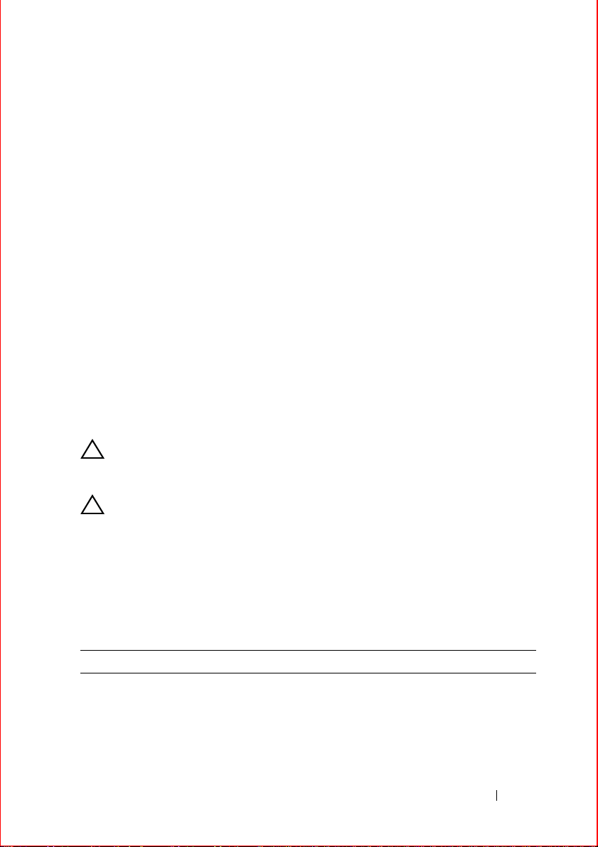
2 Attach the brackets to the sides of the chassis on either side using four
screws for each bracket.
Attach the bracket so that the “ear” faces to the outside of the chassis.
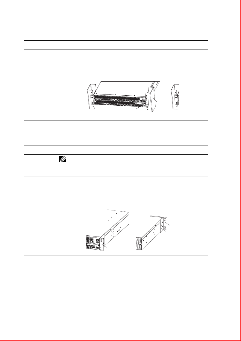
Install a Chassis into the Rack or Cabinet
To install the chassis into a rack or cabinet, follow these steps:
Step Task
NOTE: Dell Force10 recommends that one person hold the
Z9000 chassis in place while a second person attaches the brackets to
the posts.
1 Attach the bracket "ears" to the rack or cabinet posts using two screws
for each bracket. Ensure the screws are tightened firmly. The example
here shows the mounting brackets on the I/O side, but you can use either
side.
6 Installing the Hardware
 Loading...