

Dell Force10 S60, Force10 S55 Quick Start Manual
Dell Force10
S55 and S60 Systems
Quick Start Guide
Regulatory Model: S55/S60


Dell Force10
S55 and S60 Systems
Quick Start Guide
Regulatory Model: S55/S60

Notes, Cautions, and Warnings
NOTE: A NOTE indicates important information that helps you make better use
of your computer.
CAUTION: A CAUTION indicates potential damage to hardware or loss of
data if instructions are not followed.
WARNING: A WARNING indicates a potential for property damage,
personal injury, or death.
If you purchased a Dell n Series computer, any references in this publication to
Microsoft
Windows operating systems are not applicable.
____________________
Information in this publication is subject to change without notice.
© 2011 Dell Inc.All rights reserved.
Reproduction of these materials in any manner whatsoever without the written permission of Dell Inc.
is strictly forbidden.
Trademarks used in this text: Dell™, the DELL logo, Dell Precision™, OptiPlex™, Latitude™,
PowerEdge™, PowerVault™, PowerConnect™, OpenManage™, EqualLogic™, KACE™,
FlexAddress™ and Vostro™ are trademarks of Dell Inc. Intel
®
, Pentium®, Xeon®, Core™ and
Celeron
®
are registered trademarks of Intel Corporation in the U.S. and other countries. AMD® is a
registered trademark and AMD Opteron™, AMD Phenom™, and AMD Sempron™ are trademarks
of Advanced Micro Devices, Inc. Microsoft
®
, Windows®, Windows Server®, MS-DOS® and
Windows V ista
®
are either trademarks or registered trademarks of Microsoft Corporation in the United
States and/or other countries. Red Hat Enterprise Linux
®
and Enterprise Linux® are registered
trademarks of Red Hat, Inc. in the United States and/or other countries. Novell
®
is a registered
trademark and SUSE ™ is a trademark of Novell Inc. in the United States and other countries. Oracle
®
is a registered trademark of Oracle Corporation and/or its affiliates. Citrix
®
, Xen®, XenServer® and
XenMotion
®
are either registered trademarks or trademarks of Citrix Systems, Inc. in the United States
and/or other countries. VMware
®
, Vir tual SMP®, vMotion®, vCenter®, and vSphere® are registered
trademarks or trademarks of VMWare, Inc. in the United States or other countries.
Other trademarks and trade names may be used in this publication to refer to either the entities claiming
the marks and names or their products. Dell Inc. disclaims any proprietary interest in trademarks and
trade names other than its own.
Regulatory Model: S55/S60
2011 - 9 P/N 045FRK Rev. A00

About this Guide 3
About this Guide
This document is intended as a Quick Start Guide to get new systems up and
running and ready for configuration. For complete installation and configuration
information, refer to the following documents:
Documentation S55 S60
Hardware installation and
power-up instructions
Installing the S55 System Installing the S60 System
Software configuration FTOS Configuration Guide
for the S55 System
FTOS Configuration Guide
for the S60 System
Command line interface FTOS Command Refer ence
for the S55 System
FTOS Command Reference
for the S60 System
Latest updates Release Notes for the S55
System
Release Notes for the S60
System

4 About this Guide

Installing the Hardware 5
1
Installing the Hardware
This guide assumes all site preparation has been performed before installing the
chassis.
Installing the Chassis in a Rack or Cabinet
To install the S55 or S60 systems, Dell Force10 recommends that you complete
the installation procedures in the order presented below.
NOTE: Unless stated otherwise, the installation instructions below apply to both
the S55 and S60 chassis.
Always handle the system and its components with care. Avoid dropping the
switch or its field replaceable units.
CAUTION: Always wear an ESD-preventive wrist or heel ground strap when
handling the chassis and its components. As with all electrical devices of this
type, take all necessary safety precautions to prevent injury when installing
this system. Electrostatic discharge (ESD) damage c a n occ ur if components
are mishandled.
Attaching Mounting Brackets
The chassis is shipped with mounting brackets (rack ears) and required screws
for rack or cabinet installation. The brackets are enclosed in a package with the
chassis.
NOTE: Dell Force10 recommends attaching the brackets at the PSU side. This
provides the greatest weight support for the chassis in the rack or cabinet.
.
Step Task
1 Take the brackets and screws out of their packaging.
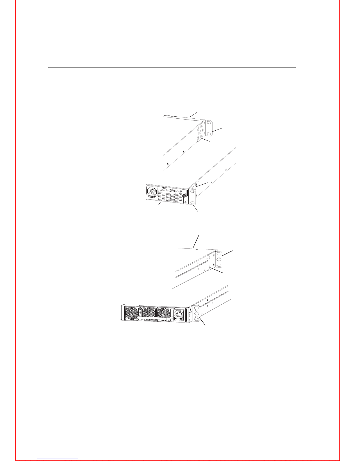
6 Installing the Hardware
2 Attach the brackets to the sides of the chassis at the PSU end, using four
screws for each bracket. Attach the bracket so that the “ear” faces the
PSU and the outside of the chassis.
S55
S60
Step Task
Power Supply/Fan Module
View from Chassis Rear
View from Chassis Front
Screws
Connect to
Rack/Cabinet
(ears)
Connect to
Rack/Cabinet
(ears)
Screws
Power Supply/Fan Module
Power Supply
Power Supply
Screws
Connect to
rack/cabinet
(ear)
Connect to
rack/cabinet
(ear)
View of chassis front
View from chassis rear

Installing the Hardware 7
Install Chassis into Rack or Cabinet
Ensure that there is adequate clearance surrounding the rack or within the
cabinet to permit access and airflow.
Attach a Ground Cable to the System
The system is shipped with necessary 10-32 screw(s) for attaching a ground
cable to the chassis. The cable itself is not included. Dell Force10 recommends a
6AWG one-ho le (for the S55) or two-hole (for the S60) lug, #10 hole size, 63"
spacing (not included in shipping) to properly ground the chassis. The lug must
be a UL recognized, crimp-type lug.
NOTE: The rack installation ears are not suitable for grounding.
CAUTION: Grounding conductors must be made of copper. Do not use
aluminum conductors.
Step Task
1 Dell Force10 recommends that one person hold the chassis in place
while a second person attaches the brackets to the posts.
2 Attach the bracket "ears" to the rack or cabinet posts, using two screws
for each bracket. Ensure the screws are tightened firmly.
S55
S60
PSU0
PSU1
Rack/Cabinet
Post
Rack Mounting
ears
Rack/Cabinet
Post
Rack Mounting
"ears"
PSU0
PSU1
 Loading...