

Page 1

Dell™ EC280
Owner’s Manual
Model EC280
www.dell.com | support.dell.com
Page 2

Notes, Notices, and Cautions
NOTE: A NOTE indicates important information that helps you make better use of your computer.
NOTICE: A NOTICE indicates either potential damage to hardware or loss of data and tells you how to avoid the
problem.
CAUTION: A CAUTION indicates a potential for property damage, personal injury, or death.
____________________
Information in this document is subject to change without notice.
© 2007 Dell Inc. All rights reserved.
Reproduction in any manner whatsoever without the written permission of Dell Inc. is strictly forbidden.
Trademarks used in this text: Dell and the DELL logo are trademarks of Dell Inc.; Intel, Pentium, and Celeron are registered trademarks of
Intel Corporation; Microsoft and Windows are registered trademarks of Microsoft Corporation.
Other trademarks and trade names may be used in this document to refer to either the entities claiming the marks and names or their products.
Dell Inc. disclaims any proprietary interest in trademarks and trade names other than its own.
Model EC280
March 2007 P/N RW965 Rev. A00
Page 3

Contents
Finding Information . . . . . . . . . . . . . . . . . . . . . . . . . . . . . . . . . . . . . . . . . . . . . . . . . . . . . . . . . . . . . 7
1 Setting Up and Using Your Computer . . . . . . . . . . . . . . . . . . . . . . . . . 10
Front View of the Computer . . . . . . . . . . . . . . . . . . . . . . . . . . . . . . . . . . . . . . . . . . . . . . . . . . . . . 11
Back View of the Computer . . . . . . . . . . . . . . . . . . . . . . . . . . . . . . . . . . . . . . . . . . . . . . . . . . . . . 12
Installing Drivers for Your Computer . . . . . . . . . . . . . . . . . . . . . . . . . . . . . . . . . . . . . . . . . . . . . 14
Setting Up a Printer (USB type) . . . . . . . . . . . . . . . . . . . . . . . . . . . . . . . . . . . . . . . . . . . . . . . . . . 15
Printer Cable . . . . . . . . . . . . . . . . . . . . . . . . . . . . . . . . . . . . . . . . . . . . . . . . . . . . . . . . . . . . . . . . 15
Connecting a USB Printer. . . . . . . . . . . . . . . . . . . . . . . . . . . . . . . . . . . . . . . . . . . . . . . . . . . . . 15
Connecting to the Internet . . . . . . . . . . . . . . . . . . . . . . . . . . . . . . . . . . . . . . . . . . . . . . . . . . . . . . 16
Setting Up Your Internet Connection . . . . . . . . . . . . . . . . . . . . . . . . . . . . . . . . . . . . . . . . . . . 16
Playing CDs and DVDs. . . . . . . . . . . . . . . . . . . . . . . . . . . . . . . . . . . . . . . . . . . . . . . . . . . . . . . . . . 17
Adjusting the Volume. . . . . . . . . . . . . . . . . . . . . . . . . . . . . . . . . . . . . . . . . . . . . . . . . . . . . . . . . 19
Adjusting the Picture . . . . . . . . . . . . . . . . . . . . . . . . . . . . . . . . . . . . . . . . . . . . . . . . . . . . . . . . . 19
Setting Up a Home and Office Network. . . . . . . . . . . . . . . . . . . . . . . . . . . . . . . . . . . . . . . . . . . 20
Connecting to a Network Adapter. . . . . . . . . . . . . . . . . . . . . . . . . . . . . . . . . . . . . . . . . . . . . . 20
Network Setup Wizard . . . . . . . . . . . . . . . . . . . . . . . . . . . . . . . . . . . . . . . . . . . . . . . . . . . . . . . 20
Power Management . . . . . . . . . . . . . . . . . . . . . . . . . . . . . . . . . . . . . . . . . . . . . . . . . . . . . . . . . . . 21
Standby Mode. . . . . . . . . . . . . . . . . . . . . . . . . . . . . . . . . . . . . . . . . . . . . . . . . . . . . . . . . . . . . . . 21
Hibernate Mode . . . . . . . . . . . . . . . . . . . . . . . . . . . . . . . . . . . . . . . . . . . . . . . . . . . . . . . . . . . . . 21
Page 4

Power Options Properties . . . . . . . . . . . . . . . . . . . . . . . . . . . . . . . . . . . . . . . . . . . . . . . . . . . . . . . 22
Power Schemes Tab. . . . . . . . . . . . . . . . . . . . . . . . . . . . . . . . . . . . . . . . . . . . . . . . . . . . . . . . . . 22
Advanced Tab . . . . . . . . . . . . . . . . . . . . . . . . . . . . . . . . . . . . . . . . . . . . . . . . . . . . . . . . . . . . . . . 23
Hibernate Tab. . . . . . . . . . . . . . . . . . . . . . . . . . . . . . . . . . . . . . . . . . . . . . . . . . . . . . . . . . . . . . . . 23
2 Solving Problems . . . . . . . . . . . . . . . . . . . . . . . . . . . . . . . . . . . . . . . . . . 24
Troubleshooting Tips . . . . . . . . . . . . . . . . . . . . . . . . . . . . . . . . . . . . . . . . . . . . . . . . . . . . . . . . . . . 24
Battery Problems. . . . . . . . . . . . . . . . . . . . . . . . . . . . . . . . . . . . . . . . . . . . . . . . . . . . . . . . . . . . . . . 24
Drive Problems . . . . . . . . . . . . . . . . . . . . . . . . . . . . . . . . . . . . . . . . . . . . . . . . . . . . . . . . . . . . . . . . 24
CD and DVD Drive Problems . . . . . . . . . . . . . . . . . . . . . . . . . . . . . . . . . . . . . . . . . . . . . . . . . . . 25
Problems writing to a CD/DVD-RW drive . . . . . . . . . . . . . . . . . . . . . . . . . . . . . . . . . . . . . . . . 25
Hard Drive Problems. . . . . . . . . . . . . . . . . . . . . . . . . . . . . . . . . . . . . . . . . . . . . . . . . . . . . . . . . . 26
E-Mail, Modem, and Internet Problems . . . . . . . . . . . . . . . . . . . . . . . . . . . . . . . . . . . . . . . . . . . 26
Error Messages . . . . . . . . . . . . . . . . . . . . . . . . . . . . . . . . . . . . . . . . . . . . . . . . . . . . . . . . . . . . . . . . 27
Keyboard Problems. . . . . . . . . . . . . . . . . . . . . . . . . . . . . . . . . . . . . . . . . . . . . . . . . . . . . . . . . . . . . 28
Lockups and Software Problems . . . . . . . . . . . . . . . . . . . . . . . . . . . . . . . . . . . . . . . . . . . . . . . . . 29
The computer does not start up . . . . . . . . . . . . . . . . . . . . . . . . . . . . . . . . . . . . . . . . . . . . . . . . 29
The computer stops responding. . . . . . . . . . . . . . . . . . . . . . . . . . . . . . . . . . . . . . . . . . . . . . . . 29
A program stops responding. . . . . . . . . . . . . . . . . . . . . . . . . . . . . . . . . . . . . . . . . . . . . . . . . . . 29
A program crashes repeatedly . . . . . . . . . . . . . . . . . . . . . . . . . . . . . . . . . . . . . . . . . . . . . . . . . 29
A program is designed for an earlier Windows operating system . . . . . . . . . . . . . . . . . . . 30
A solid blue screen appears . . . . . . . . . . . . . . . . . . . . . . . . . . . . . . . . . . . . . . . . . . . . . . . . . . . 30
Other software problems . . . . . . . . . . . . . . . . . . . . . . . . . . . . . . . . . . . . . . . . . . . . . . . . . . . . . . 30
Memory Problems . . . . . . . . . . . . . . . . . . . . . . . . . . . . . . . . . . . . . . . . . . . . . . . . . . . . . . . . . . . . . . 31
Mouse Problems . . . . . . . . . . . . . . . . . . . . . . . . . . . . . . . . . . . . . . . . . . . . . . . . . . . . . . . . . . . . . . . 31
Network Problems . . . . . . . . . . . . . . . . . . . . . . . . . . . . . . . . . . . . . . . . . . . . . . . . . . . . . . . . . . . . . 32
Power Problems . . . . . . . . . . . . . . . . . . . . . . . . . . . . . . . . . . . . . . . . . . . . . . . . . . . . . . . . . . . . . . . 32
Printer Problems . . . . . . . . . . . . . . . . . . . . . . . . . . . . . . . . . . . . . . . . . . . . . . . . . . . . . . . . . . . . . . . 33
Sound and Speaker Problems. . . . . . . . . . . . . . . . . . . . . . . . . . . . . . . . . . . . . . . . . . . . . . . . . . . . 34
No sound from speakers . . . . . . . . . . . . . . . . . . . . . . . . . . . . . . . . . . . . . . . . . . . . . . . . . . . . . . 34
No sound from headphones . . . . . . . . . . . . . . . . . . . . . . . . . . . . . . . . . . . . . . . . . . . . . . . . . . . 35
Video and Monitor Problems . . . . . . . . . . . . . . . . . . . . . . . . . . . . . . . . . . . . . . . . . . . . . . . . . . . . 35
Page 5

The screen is blank . . . . . . . . . . . . . . . . . . . . . . . . . . . . . . . . . . . . . . . . . . . . . . . . . . . . . . . . . . 36
The screen is difficult to read . . . . . . . . . . . . . . . . . . . . . . . . . . . . . . . . . . . . . . . . . . . . . . . . . 36
3 Removing and Installing Parts . . . . . . . . . . . . . . . . . . . . . . . . . . . . . . . 37
Before You Begin . . . . . . . . . . . . . . . . . . . . . . . . . . . . . . . . . . . . . . . . . . . . . . . . . . . . . . . . . . . . . . 37
Recommended Tools . . . . . . . . . . . . . . . . . . . . . . . . . . . . . . . . . . . . . . . . . . . . . . . . . . . . . . . . . 37
Turning Off Your Computer . . . . . . . . . . . . . . . . . . . . . . . . . . . . . . . . . . . . . . . . . . . . . . . . . . . . 37
Before Working Inside Your Computer. . . . . . . . . . . . . . . . . . . . . . . . . . . . . . . . . . . . . . . . . . 38
Removing the Computer Cover. . . . . . . . . . . . . . . . . . . . . . . . . . . . . . . . . . . . . . . . . . . . . . . . . . . 38
Inside View of Your Computer . . . . . . . . . . . . . . . . . . . . . . . . . . . . . . . . . . . . . . . . . . . . . . . . . . . 40
System Board Components. . . . . . . . . . . . . . . . . . . . . . . . . . . . . . . . . . . . . . . . . . . . . . . . . . . . . . 42
Memory . . . . . . . . . . . . . . . . . . . . . . . . . . . . . . . . . . . . . . . . . . . . . . . . . . . . . . . . . . . . . . . . . . . . . . 42
Removing Memory . . . . . . . . . . . . . . . . . . . . . . . . . . . . . . . . . . . . . . . . . . . . . . . . . . . . . . . . . . . 43
Installing Memory . . . . . . . . . . . . . . . . . . . . . . . . . . . . . . . . . . . . . . . . . . . . . . . . . . . . . . . . . . . 44
Battery . . . . . . . . . . . . . . . . . . . . . . . . . . . . . . . . . . . . . . . . . . . . . . . . . . . . . . . . . . . . . . . . . . . . . . . 45
Replacing the Battery . . . . . . . . . . . . . . . . . . . . . . . . . . . . . . . . . . . . . . . . . . . . . . . . . . . . . . . . 45
Replacing the Computer Cover . . . . . . . . . . . . . . . . . . . . . . . . . . . . . . . . . . . . . . . . . . . . . . . . . . 47
4 Safety, Environmental, and Ergonomic Instructions . . . . . . . . . . . . 48
Safety Instructions. . . . . . . . . . . . . . . . . . . . . . . . . . . . . . . . . . . . . . . . . . . . . . . . . . . . . . . . . . . 48
Power Safety. . . . . . . . . . . . . . . . . . . . . . . . . . . . . . . . . . . . . . . . . . . . . . . . . . . . . . . . . . . . . . . . 49
Battery Safety . . . . . . . . . . . . . . . . . . . . . . . . . . . . . . . . . . . . . . . . . . . . . . . . . . . . . . . . . . . . . . . 50
Equipment Protection Instructions . . . . . . . . . . . . . . . . . . . . . . . . . . . . . . . . . . . . . . . . . . . . . 50
Page 6

5 Appendix . . . . . . . . . . . . . . . . . . . . . . . . . . . . . . . . . . . . . . . . . . . . . . . . . 52
Specifications . . . . . . . . . . . . . . . . . . . . . . . . . . . . . . . . . . . . . . . . . . . . . . . . . . . . . . . . . . . . . . . . . 52
System Setup . . . . . . . . . . . . . . . . . . . . . . . . . . . . . . . . . . . . . . . . . . . . . . . . . . . . . . . . . . . . . . . . . . 54
Overview. . . . . . . . . . . . . . . . . . . . . . . . . . . . . . . . . . . . . . . . . . . . . . . . . . . . . . . . . . . . . . . . . . . . 54
Entering System Setup . . . . . . . . . . . . . . . . . . . . . . . . . . . . . . . . . . . . . . . . . . . . . . . . . . . . . . . . 54
System Setup Options. . . . . . . . . . . . . . . . . . . . . . . . . . . . . . . . . . . . . . . . . . . . . . . . . . . . . . . . . 55
Boot Menu . . . . . . . . . . . . . . . . . . . . . . . . . . . . . . . . . . . . . . . . . . . . . . . . . . . . . . . . . . . . . . . . . . 58
Clearing Forgotten Passwords and CMOS Settings. . . . . . . . . . . . . . . . . . . . . . . . . . . . . . . . . 59
Jumper Location . . . . . . . . . . . . . . . . . . . . . . . . . . . . . . . . . . . . . . . . . . . . . . . . . . . . . . . . . . . . . 60
Clearing CMOS and Password Settings . . . . . . . . . . . . . . . . . . . . . . . . . . . . . . . . . . . . . . . . . 60
Cleaning Your Computer . . . . . . . . . . . . . . . . . . . . . . . . . . . . . . . . . . . . . . . . . . . . . . . . . . . . . . . . 61
Computer, Keyboard, and Monitor . . . . . . . . . . . . . . . . . . . . . . . . . . . . . . . . . . . . . . . . . . . . . . 61
Mouse . . . . . . . . . . . . . . . . . . . . . . . . . . . . . . . . . . . . . . . . . . . . . . . . . . . . . . . . . . . . . . . . . . . . . . 61
CDs and DVDs . . . . . . . . . . . . . . . . . . . . . . . . . . . . . . . . . . . . . . . . . . . . . . . . . . . . . . . . . . . . . . . 62
Contacting Dell . . . . . . . . . . . . . . . . . . . . . . . . . . . . . . . . . . . . . . . . . . . . . . . . . . . . . . . . . . . . . . . . 63
Glossary . . . . . . . . . . . . . . . . . . . . . . . . . . . . . . . . . . . . . . . . . . . . . . . . . . . . . 64
Index . . . . . . . . . . . . . . . . . . . . . . . . . . . . . . . . . . . . . . . . . . . . . . . . . . . . . . . . 75
Page 7
Finding Information
NOTE: Some features or media may be optional and may not ship with your computer. Some features or
media may not be available in certain countries.
NOTE: Additional information may ship with your computer.
What Are You Looking For? Find It Here
• Drivers for my computer
• My device documentation
• Warranty information
•Safety instructions
• Regulatory information
• Ergonomics information
• End User License Agreement
• How to set up my computer
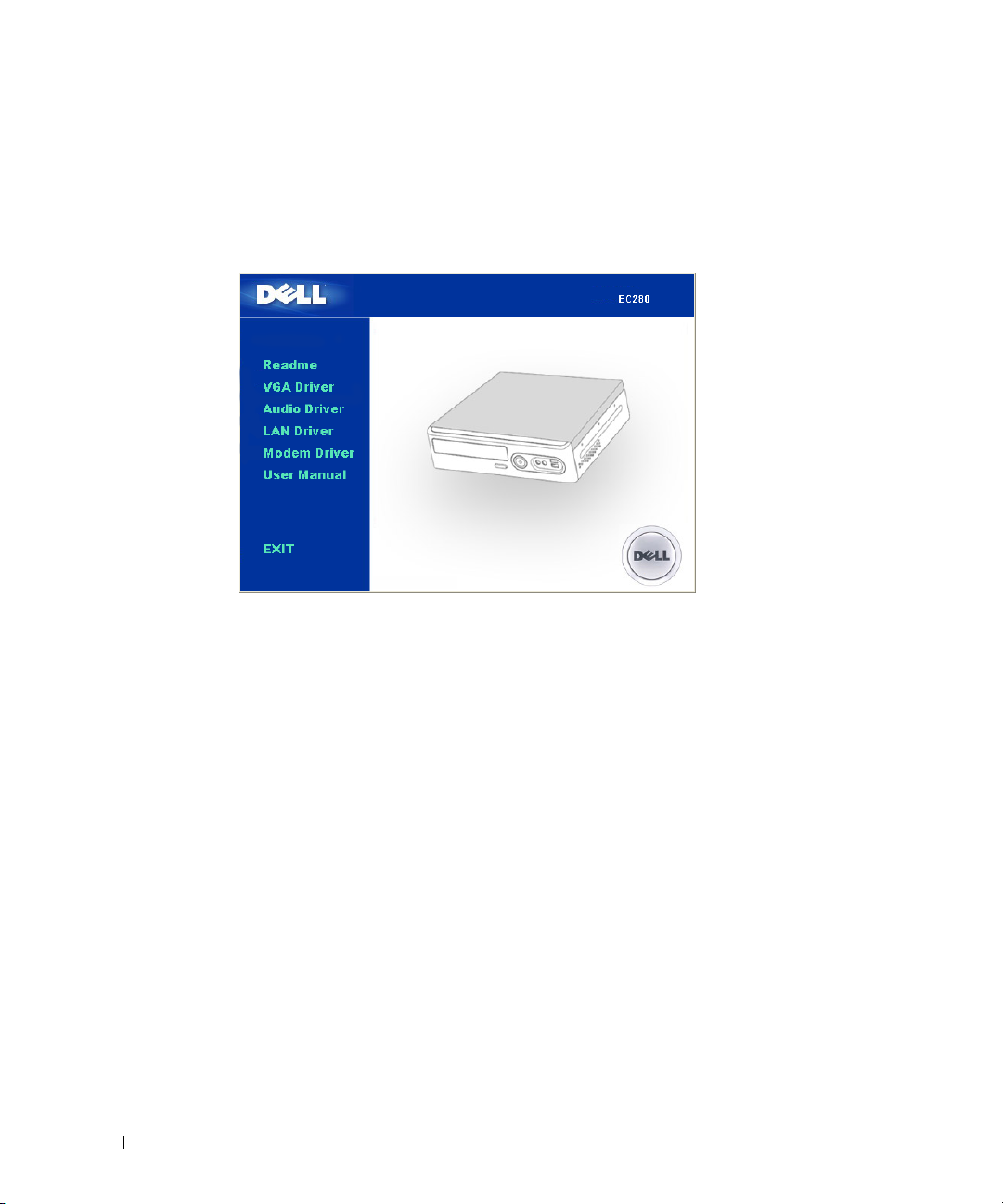
Drivers and Utilities CD (also known as Resource CD)
NOTE: The
may not ship with your computer.
Readme files may be included on your CD to provide
last-minute updates about technical changes to your
computer or advanced technical reference material for
technicians or experienced users.
NOTE: Drivers and documentation updates can be found at
support.dell.com.
NOTE: You may need to purchase Microsoft Windows
separately.
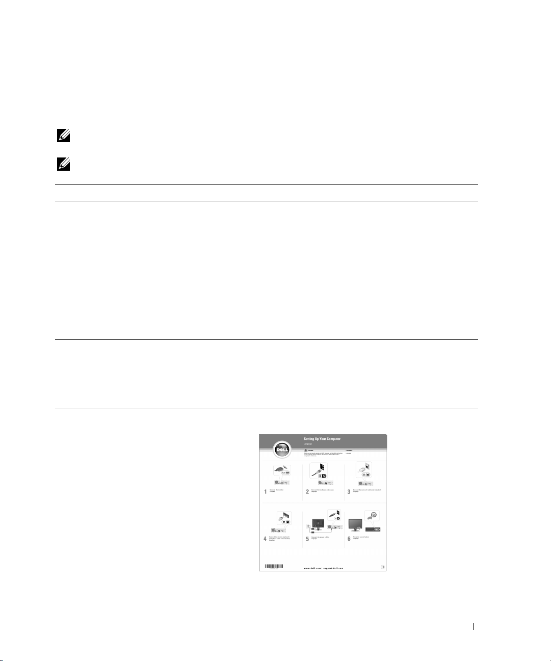
Dell™ Owner’s Manual
Setup Diagram
Drivers and Utilities
CD may be optional and
7
Page 8
What Are You Looking For? Find It Here
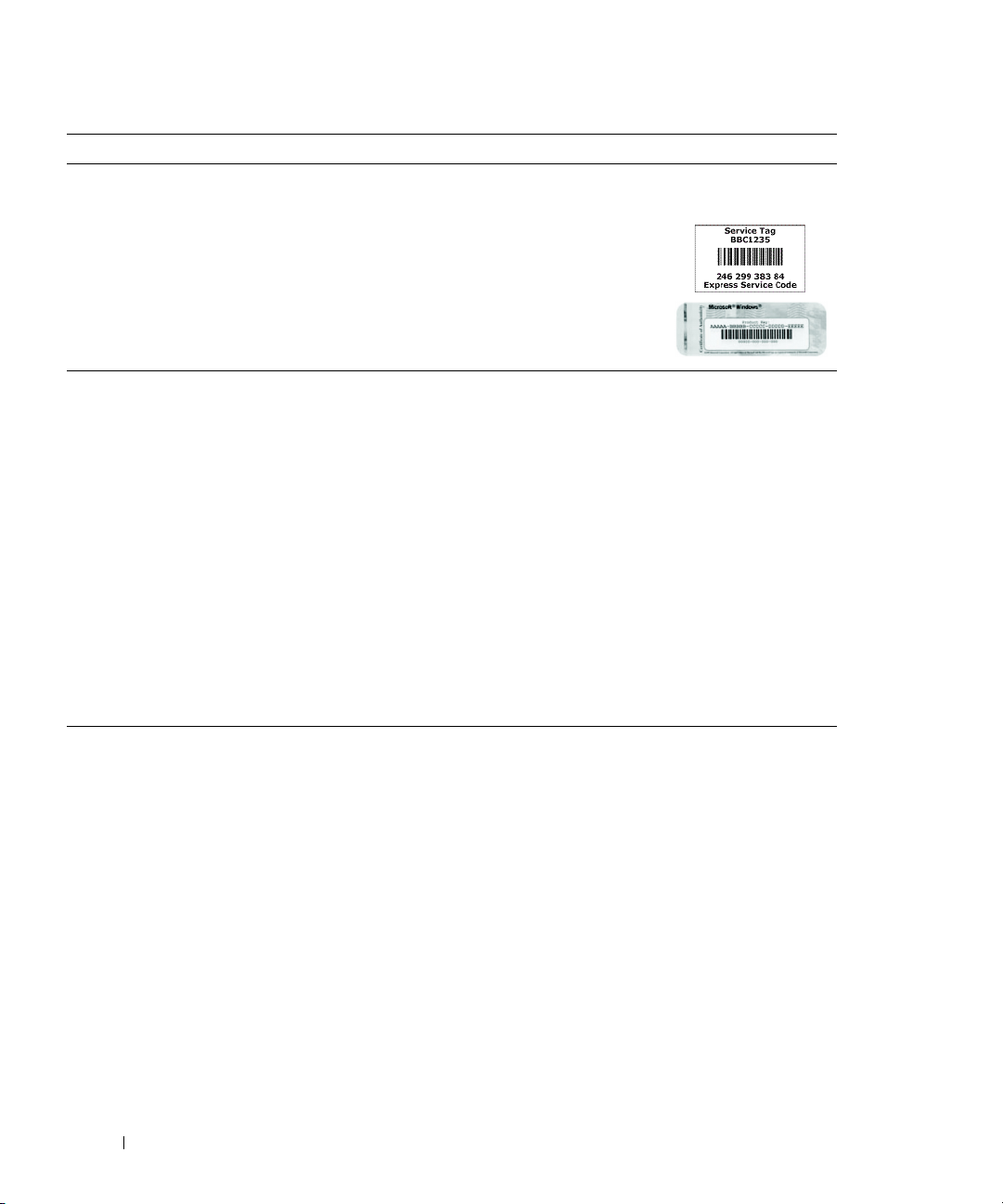
• Service Tag and Express Service Code
• Microsoft Windows License Label (optional)
Service Tag and Microsoft® Windows® License
These labels are located on your computer.
•Use the Service Tag to
identify your computer when
you use
contact support.
• Enter the Express Service
Code to di rect your call when
contacting support.
• Solutions — Troubleshooting hints and tips,
articles from technicians, online courses, and
frequently asked questions
Dell Support Website — support.dell.com
NOTE: Select your region or business segment to view the
appropriate support site.
• Community — Online discussion with other Dell
customers
• Customer Care — Contact information, service
call and order status, warranty, and repair
information
• Service and Support — Service call status, support
history, service contract, and online discussions
with support
• Reference — Computer documentation, details on
my computer configuration, product
specifications, and white papers
• Downloads — Certified drivers, patches, and
software updates
• How to use Windows XP
• How to work with programs and files
•How to personalize my
NOTE: The support.dell.com user interface may vary
depending on your selections.
Windows Help and Support Center
1
Click
Start>Help and Support
2
Type a word or phrase that describes your problem, and
then click the arrow icon.
3
Click the topic that describes your problem.
4
Follow the instructions on the screen.
support.dell.com
or
.
8
Page 9

What Are You Looking For? Find It Here
• How to reinstall my operating system
Operating System CD
NOTE: The
not ship with your computer.
After you reinstall your operating system, use the
and Utilities
the devices that came with your computer. Your
operating system product key label is located on your
computer.
NOTE: The color of your CD varies based on the operating
system you ordered.
NOTE: You may need to purchase Microsoft Windows
separately.
Operating System
CD (
Resource
CD may be optional and may
Drivers
CD) to reinstall drivers for
9
Page 10

Setting Up and Using Your Computer
CAUTION: Your computer should only be mounted horizontally. Never mount it vertically.
CAUTION: To ensure adequate cooling, do not block any of the vents.
• Ensure that there is a minimum of 2 inches of space between all vents and any object near these vents.
• Keep the vent area clean and dust-free to ensure that the system is adequately ventilated. Use only a dry
cloth to clean the vent area to avoid water damage to the system.
1
10 Setting Up and Using Your Computer
Page 11
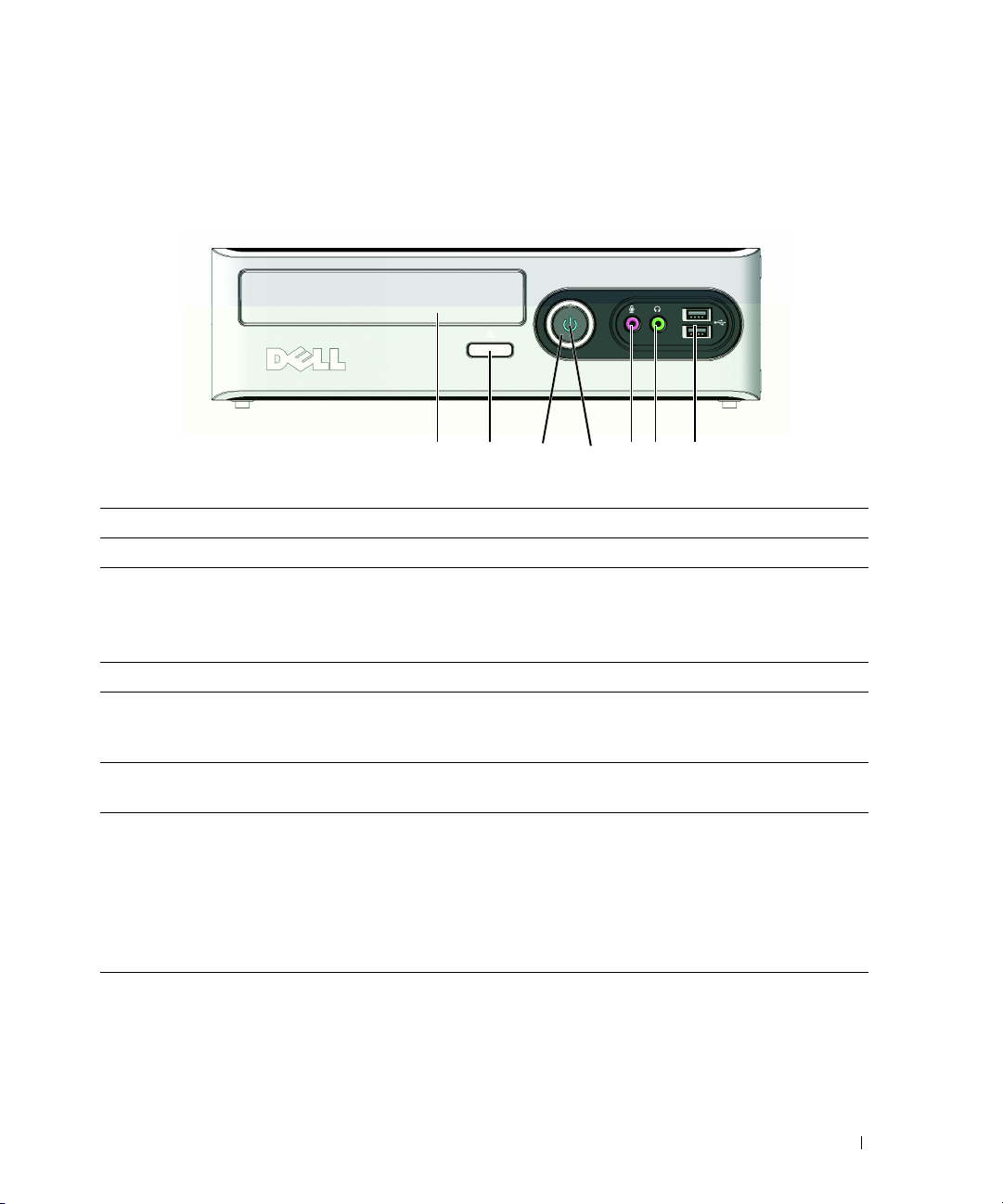
Front View of the Computer
123 5674
1 CD or DVD drive Type of drive depends on model
2 CD or DVD eject button Press to eject a disk from the CD or DVD drive.
3 power button Press to turn on the computer.
NOTICE: To avoid losing data, do not use the power button to
turn off the computer. Instead, perform an operating system
shutdown.
4 power light The power light indicates when the computer is powered on.
5 microphone connector Use the microphone connector to attach a personal computer
microphone for voice or musical input into a sound or
telephony program.
6 line-out/headphone connector Use the headphone connector to attach headphones and most
kinds of speakers.
7 USB 2.0 connectors (2) Use the front USB connectors for devices that you connect
occasionally, such as joysticks or cameras, or for bootable USB
devices (see "System Setup Options" on page 55 for more
information on booting to a USB device).
It is recommended that you use the back USB connectors for
devices that typically remain connected, such as printers and
keyboards.
Setting Up and Using Your Computer 11
Page 12
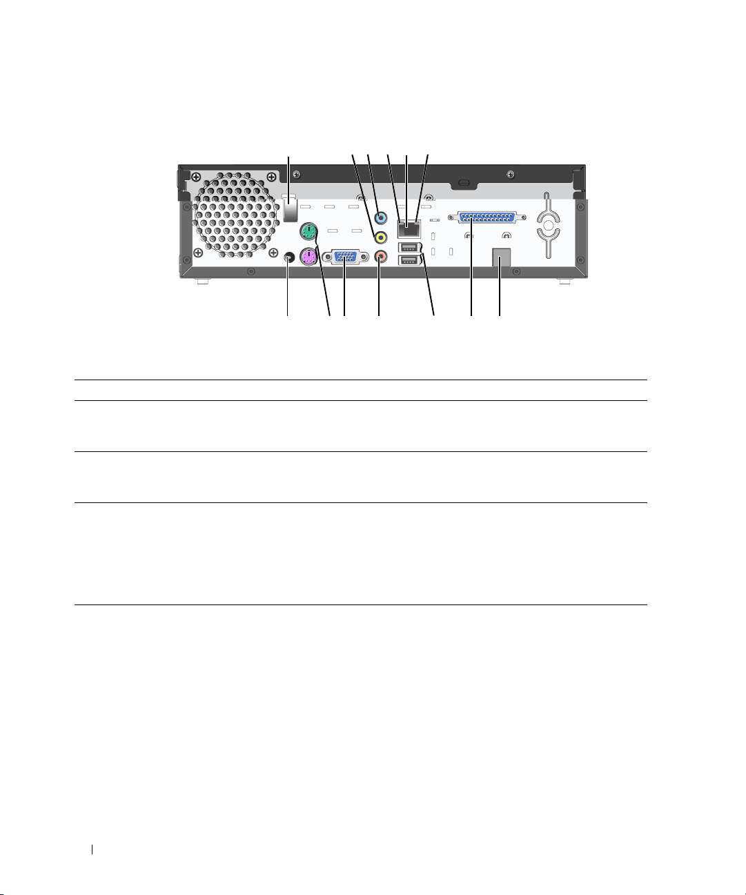
Back View of the Computer
1
13 12 11 10 9 8 7
1 cable clip Use to hold DC-in or other cables.
2 line-out/headphone connector Use the (green) line-out connector to attach
3 line-in connector Use the (blue) line-in connector to attach a
4 link integrity light
45632
headphones and most speakers with integrated
amplifiers.
record/playback device such as a cassette player, CD
player, or VCR.
• Green — A good connection exists between a 10Mbps network and the computer.
• Orange — A good connection exists between a 100Mbps network and the computer.
• Off — The computer is not detecting a physical
connection to the network.
12 Setting Up and Using Your Computer
Page 13

5 network adapter connector NOTICE: Do not plug a telephone cable into the network
connector.
Use the network adapter connector to attach your
computer to a network or broadband device. Connect
one end of a network cable to either a network jack or
your network or broadband device, and then connect
the other end of the network cable to the network
adapter connector on your computer. A click indicates
that the network cable has been securely attached.
On computers with an additional network connector
card, use the connectors on the card and on the back of
the computer when setting up multiple network
connections (such as a separate intra- and extranet).
NOTE: It is recommended that you use Category 5 wiring
and connectors for your network. If you must use
Category 3 wiring, force the network speed to 10 Mbps to
ensure reliable operation.
6 network activity light Flashes a yellow light when the computer is
transmitting or receiving network data. A high volume
of network traffic may make this light appear to be in a
steady "on" state.
7 modem (optional) Connect to internet using a dial-up connection.
8 parallel port Connect compatible printers or scanners here.
9 USB 2.0 connectors (2)
(rear quad)
Use the back, rear-quad USB connectors for devices
that typically remain connected, such as printers and
keyboards.
NOTE: It is recommended that you use the front USB
connectors for devices that you connect occasionally,
such as joysticks, cameras, or bootable USB devices.
10 microphone connector Use the (pink) microphone connector to attach a
personal computer microphone for voice or musical
input into a sound or telephony program.
On computers with a sound card, use the connector on
the card.
11 VGA video connector If your monitor has a VGA connector, plug it into the
VGA connector on the computer.
12 PS-2 connectors Connect PS-2 keyboard and mouse
13 DC-in connector Connect the AC adapter.
Setting Up and Using Your Computer 13
Page 14
Installing Drivers for Your Computer
To install drivers:
Insert
1
2
3
4
5
6
Drivers and Utilities
installation screen appears.
Click on
Click on
Click on
If you have a modem, click on
Once all driver insallation is complete, click on
VGA Driver
Audio Driver
LAN Driver
CD into CD /DVD drive. The installation starts automatically and the
and follow the instructions to complete installation.
and follow the instructions to complete installation.
and follow the instructions to complete installation.
Modem Driver
and follow the instructions to complete installation.
EXIT
.
14 Setting Up and Using Your Computer
Page 15
Setting Up a Printer (USB type)
NOTICE: Complete the operating system setup before you connect a printer to the computer.
See the documentation that came with the printer for setup information, including how to:
• Obtain and install updated drivers
• Connect the printer to the computer
• Load paper and install the toner or ink cartridge
For technical assistance, refer to the printer owner's manual or contact the printer manufacturer.
Printer Cable
Your printer connects to your computer with a USB cable. Your printer may not come with a printer
cable, so if you purchase a cable separately, ensure that it is compatible with your printer. If you
purchased a printer cable at the same time you purchased your computer, the cable may arrive in the
computer box.
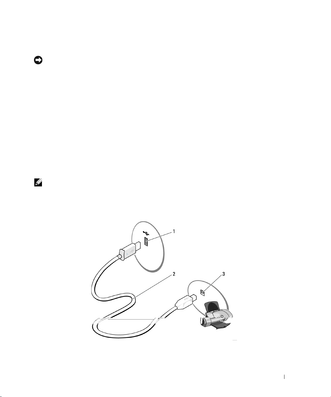
Connecting a USB Printer
NOTE: You can connect USB devices while the computer is turned on.
1
Complete the operating system setup, if you have not already done so.
2
Attach the USB printer cable to the USB connectors on the computer and the printer. The USB
connectors only fit into the ports when correctly oriented.
1 USB connector on computer 2 USB printer cable 3 USB connector on printer
Setting Up and Using Your Computer 15
Page 16

3
Turn on the printer and then turn on the computer. If the
appears, click
4
Install the printer driver, if necessary. See the documentation that came with your printer.
Cancel
.
Add New Hardware Wizard
window
Connecting to the Internet
NOTE: ISPs and ISP offerings vary by country.
To connect to the Internet, you need a modem or network connection and an Internet service provider
(ISP), such as AOL or MSN. Your ISP will offer one or more of the following Internet connection
options:
• Dial-up connections that provide Internet access through a telephone line. Dial-up connections are
considerably slower than DSL and cable modem connections.
• DSL connections that provide high-speed Internet access through your existing telephone line. With a
DSL connection, you can access the Internet and use your telephone on the same line simultaneously.
• Cable modem connections that provide high-speed Internet access through your local cable TV line.
If you are using a dial-up connection, connect a telephone line to the modem connector on your
computer and to the telephone wall jack before you set up your Internet connection. If you are using a
DSL or cable modem connection, contact your ISP for setup instructions.
Setting Up Your Internet Connection
To set up an Internet connection with a provided ISP desktop shortcut:
1
Save and close any open files, and exit any open programs.
2
Double-click the ISP icon on the Microsoft® Windows® desktop.
3
Follow the instructions on the screen to complete the setup.
If you do not have an ISP icon on your desktop or if you want to set up an Internet connection with a
different ISP:
1
Save and close any open files, and exit any open programs.
2
Click the
The
3
Click
4
In the next window, click the appropriate option:
• If you do not have an ISP and want to select one, click
• If you have already obtained setup information from your ISP, but you did not receive a setup CD,
• If you have a CD, click
Start
button, then click
New Connection Wizard
Connect to the Internet
providers (ISPs)
click
Set up my connection manually
.
Use the CD I got from an ISP
Internet Explorer
appears.
.
.
.
Choose from a list of Internet service
.
16 Setting Up and Using Your Computer
Page 17
5
Click
Next
.
If you selected
on the screen to complete the setup.
NOTE: If you do not know which type of connection to select, contact your ISP.
6
Click the appropriate option under
7
Use the setup information provided by your ISP to complete the setup.
If you are having problems connecting to the Internet, see "E-Mail, Modem, and Internet Problems" on
page 26. If you cannot connect to the Internet but have successfully connected in the past, the ISP might
have a service outage. Contact your ISP to check the service status, or try connecting again later.
Set up my connection manually
How do you want to connect to the Internet?
, continue to step 6. Otherwise, follow the instructions
, and then click
Next
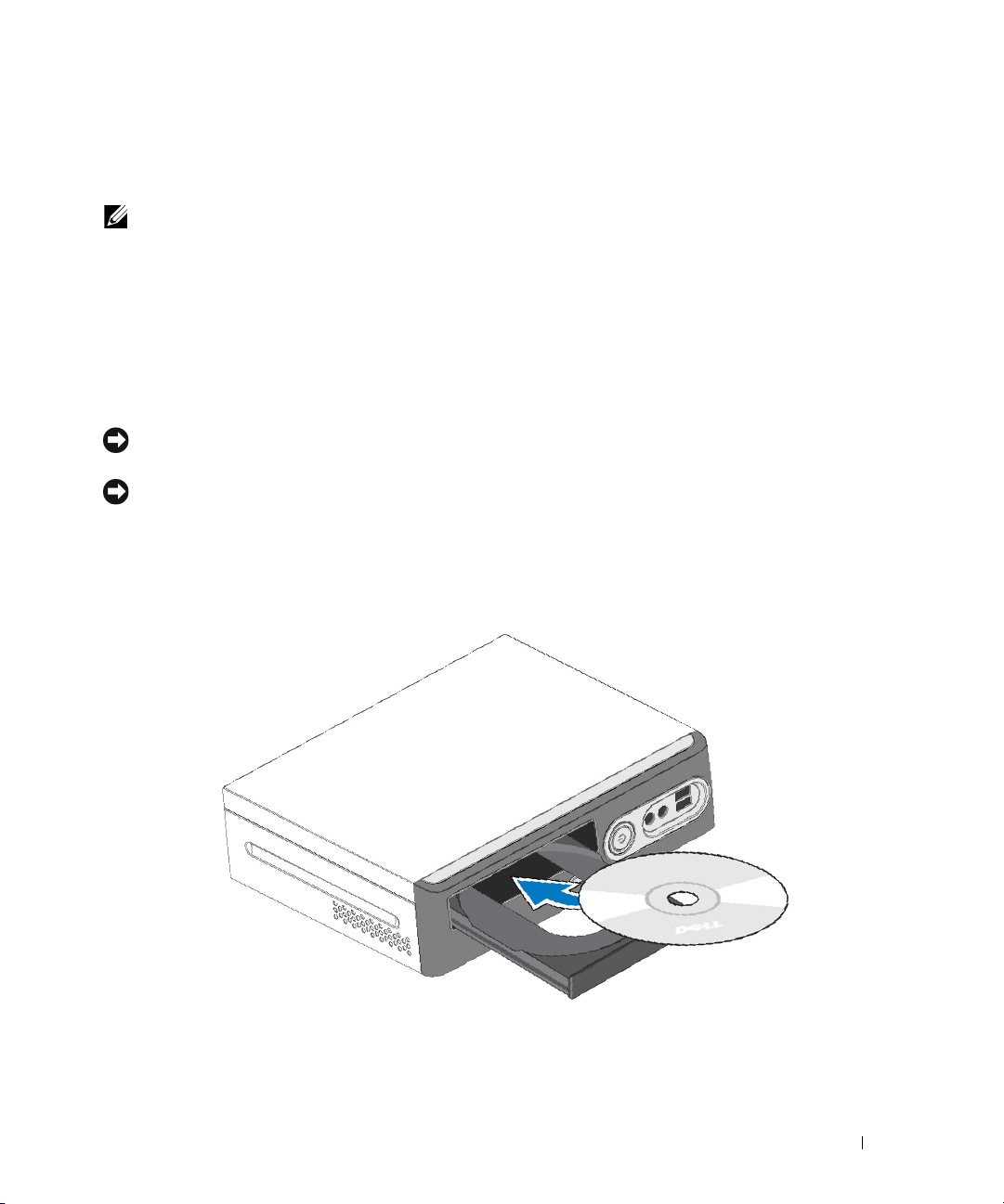
Playing CDs and DVDs
NOTICE: Do not press down on the CD or DVD tray when you open or close it. Keep the tray closed when you are
not using the drive.
NOTICE: Do not move the computer when you are playing CDs or DVDs.
1
Press the eject button on the front of the drive.
2
Place the disc, label side up in the center of the tray.
3
Press the disc into the center of the tray until it clicks into place.
.
4
Press the eject button or gently push in the tray
Setting Up and Using Your Computer 17
Page 18

To format CDs for storing data, to create music CDs, or to copy CDs, see the CD software that came
with your computer.
NOTE: Ensure that you follow all copyright laws when you create CDs.
A CD player includes the following basic buttons:
Play
Move backward within the current track
Pau se
Move forward within the current track
Stop
Go to the previous track
Eject
Go to the next track
A DVD player includes the following basic buttons:
Stop
Restart the current chapter
Play
Fast forward
Pau se
Fast reverse
Advance a single frame while in pause mode
Go to the next title or chapter
Continuously play the current title or chapter
Go to the previous title or chapter
Eject
For more information on playing CDs or DVDs, click Help on the CD or DVD player (if available).
18 Setting Up and Using Your Computer
Page 19

Adjusting the Volume
NOTE: When the speakers are muted, you do not hear the CD or DVD playing.
1
Click the
Control
2
In the
increase or decrease the volume.
For more information on volume control options, click Help in the Volume Control window.
Start
button, point to
.
Volum e Co nt ro l
All Programs>Accessories>Entertainment
window, click and drag the bar in the
Volu me Cont r ol
, and then click
column up or down to
Vo lu me
Adjusting the Picture
If an error message notifies you that the current resolution and color depth are using too much memory
and preventing DVD playback, adjust the display properties:
1
Click the
2
Under
3
Under
4
In the
800 by 600 pixels
5
Click the drop-down menu under
6
Click OK.
Start
button, then click
Pick a category
Pick a task...
Display Properties
, click
, click
.
Control Panel
Appearance and Themes
Change the screen resolution
window, click and drag the bar in
Color quality
.
.
.
, then click
Screen resolution
Medium (16 bit)
to change the setting to
.
Setting Up and Using Your Computer 19
Page 20
Setting Up a Home and Office Network
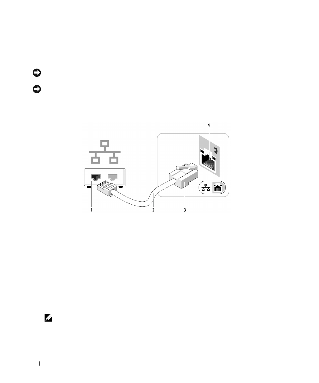
Connecting to a Network Adapter
NOTICE: Plug the network cable into the network adapter connector on the computer. Do not plug the network
cable into the modem connector on the computer.
NOTICE: Do not plug a network cable into a telephone wall jack.
1
Connect the network cable to the network adapter connector on the back of your computer.
Insert the cable until it clicks into place, and then gently pull it to ensure that it is secure.
2
Connect the other end of the network cable to a network device.
1 network device 2 network cable
3 network adapter connector 4 network connector on the back of the computer
Network Setup Wizard
The Microsoft® Windows® XP operating system provides a Network Setup Wizard to guide you through
the process of sharing files, printers, or an Internet connection between computers in a home or small
office.
1
Click the
Network Setup Wizard
2
On the welcome screen, click
3
Click
4
Complete the checklist and required preparations.
5
Return to the
20 Setting Up and Using Your Computer
Start
button, point to
.
Checklist
NOTE: Selecting the connection method This computer connects directly to the Internet enables the
integrated firewall provided with Windows XP.
for creating a network.
Network Setup Wizard
All Programs>Accessories>Communications
Next
.
and follow the instructions on the screen.
, and then click
Page 21

Power Management
The Microsoft® Windows® XP power management features can reduce the amount of electricity your
computer uses when it is on and you are not using it. You can reduce power to just the monitor or the
hard drive, or you can use standby mode or hibernate mode to reduce power to the entire computer.
When the computer exits from a power conservation mode, the Windows desktop is restored to the state
it was in before it entered the mode.
NOTE: Windows XP Professional includes security and networking features not available in Windows XP Home
Edition. When a Windows XP Professional computer is connected to a network, different options related to security
and networking appear in certain windows.
Standby Mode
Standby mode conserves power by turning off the display and the hard drive after a time-out. When the
computer exits from standby mode, it returns to the operating state it was in before it entered standby
mode.
To set standby mode to automatically activate after a defined period of inactivity:
1
Click the
2
If
Switch to Category View
Category View
3
Under
4
Under
5
Under the
and then click
To immediately activate standby mode without a period of inactivity, click the Start button, click Tu r n
Off Computer, and then click Stand by.
To exit from standby mode, press a key on the keyboard or move the mouse.
Start
button, then click
appears in the
.
Pick a category
or pick a Control Panel icon
Power Schemes
OK
.
, click
Performance and Maintenance
tab, change the settings in the drop-down boxes to those that you desire,
Control Panel
Control Panel
, click
Power Options
.
in the left of the window, click
.
.
Switch to
NOTICE: If your computer loses power while in standby mode, it may lose data.
Hibernate Mode
Hibernate mode conserves power by copying system data to a reserved area on the hard drive and then
completely turning off the computer. When the computer exits from hibernate mode, the desktop is
restored to the state it was in before it entered hibernate mode.
To activate hibernate mode:
1
Click the
2
Under
3
Under
4
Define your hibernate settings on the
"Power Options Properties" on page 22).
Start
button, then click
Pick a category
or pick a Control Panel icon
, click
Performance and Maintenance
Control Panel
, click
Power Options
Power Schemes
.
.
.
tab,
Advanced
tab, and
Setting Up and Using Your Computer 21
Hibernate
tab (see
Page 22

To exit from hibernate mode, press the power button. The computer may take a short time to exit from
hibernate mode. Pressing a key on the keyboard or moving the mouse does not bring the computer out of
hibernation because the keyboard and the mouse do not function when the computer is in hibernate
mode.
Because hibernate mode requires a special file on your hard drive with enough disk space to store the
contents of the computer memory, Dell creates an appropriately sized hibernate mode file before
shipping the computer to you. If the computer’s hard drive becomes corrupted, Windows XP recreates
the hibernate file automatically.
Power Options Properties
Define your standby mode settings, hibernate mode settings, and other power settings in the Power
Options Properties window. To access the Power Options Properties window:
1
Click the
2
Under
3
Under
4
Define your power settings on the
Power Schemes Tab
Each standard power setting is called a scheme. If you want to select one of the standard Windows
schemes installed on your computer, choose a scheme from the Power schemes drop-down menu. The
settings for each scheme appear in the fields below the scheme name. Each scheme has different settings
for starting standby or hibernate mode and for turning off the monitor and hard drive.
The Power schemes drop-down menu displays the following schemes:
•
Always On (default)
•
Home/Office Desk
power conservation.
•
Portable/Laptop
•
Presentation
•
Minimal Power Management
•
Max Battery
extended periods of time.
If you want to change the default settings for a scheme, click the drop-down menu in the Turn off
monitor, Turn off hard disks, System standby, or System hibernates field, and then select a time-out
from the displayed list. Changing the time-out for a scheme field permanently changes the default
settings for that scheme, unless you click Save As and enter a new name for the changed scheme.
Start
button, then click
Pick a category
or pick a Control Panel icon
— If you want your computer to run without interruption (using no power conservation).
— If your computer is a portable computer and you run your computer from batteries for
, click
— If you want to use your computer with no power conservation.
— If you use your computer as a home or office computer and you require minimal
— If your computer is a portable computer that you use for traveling.
Control Panel
Performance and Maintenance
, click
Power Schemes
— If you want your computer to run with minimal power conservation.
.
Power Options
tab,
.
.
Advanced
tab, and
Hibernate
tab.
22 Setting Up and Using Your Computer
Page 23

NOTICE: If you set the hard drive (hard disk) to time-out before the monitor does, your computer may appear to be
locked up. To recover, press any key on the keyboard or click the mouse. To avoid this problem, always set the
monitor to time-out before the hard drive.
Advanced Tab
The Advanced tab allows you to:
• Place the power options icon in the Windows taskbar for quick access.
• Set the computer to prompt you for your Windows password before the computer exits from standby
mode or hibernate mode.
• Program the power button to activate standby mode, activate hibernate mode, or turn off the
computer.
To program these functions, click an option from the corresponding drop-down menu, and then click
OK.
Hibernate Tab
The Hibernate tab allows you to enable hibernate mode. If you want to use the hibernate settings you
defined on the Power Schemes tab, click the Enable hibernate support check box on the Hibernate tab.
For more information on power management options:
1
Click the
2
In the
3
In the
Start
button, then click
Help and Support
window, click
Help and Support
Performance and maintenance
.
Performance and maintenance
window, click
Conserving power on your computer
.
.
Setting Up and Using Your Computer 23
Page 24

2
Solving Problems
Troubleshooting Tips
Follow these tips when you troubleshoot your computer:
• If you added or removed a part before the problem started, review the installation procedures and
ensure that the part is correctly installed.
• If a peripheral device does not work, ensure that the device is properly connected.
• If an error message appears on the screen, write down the exact message. This message may help
support personnel diagnose and fix the problem.
• If an error message occurs in a program, see the program’s documentation.
Battery Problems
CAUTION: There is a danger of a new battery exploding if it is incorrectly installed. Replace the battery
only with the same or equivalent type recommended by the manufacturer. Discard used batteries according
to the manufacturer's instructions.
CAUTION: Before you begin any of the procedures in this section, follow the safety instructions located in
"Safety, Environmental, and Ergonomic Instructions" on page 48.
REPLACE THE BATTERY — If you have to repeatedly reset time and date information after turning
on the computer, or if an incorrect time or date displays during start-up, replace the battery (see
"Battery" on page 45). If the battery still does not work properly, contact Dell (see "Contacting Dell" on
page 63).
Drive Problems
CAUTION: Before you begin any of the procedures in this section, follow the safety instructions located in
"Safety, Environmental, and Ergonomic Instructions" on page 48.
24 Solving Problems
Page 25

ENSURE THAT MICROSOFT ® WINDOWS ® RECOGNIZES THE DRIVE — Click the Start
button, then click My Computer. If the CD or DVD drive is not listed, perform a full scan with your
antivirus software to check for and remove viruses. Viruses can sometimes prevent Windows from
recognizing the drive.
TEST THE DRIVE —
• Insert another CD or DVD to eliminate the possibility that the original one is defective.
CLEAN THE DRIVE OR DISK — See "Cleaning Your Computer" on page 61.
CHECK THE CABLE CONNECTIONS
CD and DVD Drive Problems
NOTE: High-speed CD or DVD drive vibration is normal and may cause noise, which does not indicate a defect in
the drive or the CD or DVD.
NOTE: Because of different regions worldwide and different disc formats, not all DVD titles work in all DVD drives.
ADJUST THE WINDOWS VOLUME CONTROL —
• Click the speaker icon in the lower-right corner of your screen.
• Ensure that the volume is turned up by clicking the slidebar and dragging it up.
• Ensure that the sound is not muted by clicking any boxes that are checked.
CHECK THE SPEAKERS AND SUBWOOFER — See "Sound and Speaker Problems" on page 34.
Problems writing to a CD/DVD-RW drive
CLOSE OTHER PROGRAMS — The CD/DVD-RW drive must receive a steady stream of data when
writing. If the stream is interrupted, an error occurs. Try closing all programs before you write to the
CD/DVD-RW.
Solving Problems 25
Page 26

TURN OFF STANDBY MODE IN WINDOWS BEFORE WRITING TO A CD/DVD-RW DISC —
1
Click the
2
Under
3
Under
4
From the
Start
button and click
Pick a Category
, click
Control Panel
Performance and Maintenance
or pick a Control Panel icon
Power Schemes
tab, select
, click
Power Options
Always On
.
.
.
.
Hard Drive Problems
RUN CHECK DISK —
1
Click the
2
Right-click
3
Click
4
Click the
5
Under
6
Click
7
Click
Start
button, then click
Local Disk C:
Properties
To ol s
.
tab.
Error-checking
, click
.
Check Now
My Computer
.
.
Scan for and attempt recovery of bad sectors
Start
.
.
E-Mail, Modem, and Internet Problems
CAUTION: Before you begin any of the procedures in this section, follow the safety instructions located in
"Safety, Environmental, and Ergonomic Instructions" on page 48.
NOTE: Connect the modem to an analog telephone jack only. The modem does not operate while it is connected to
a digital telephone network.
CHECK THE MICROSOFT OUTLOOK® EXPRESS SECURITY SETTINGS — If you cannot open
your e-mail attachments:
1
In Outlook Express, click
2
Click
Do not allow attachments
To ol s
, click
Options
to remove the checkmark.
, and then click
Security
.
26 Solving Problems
Page 27

CHECK THE TELEPHONE LINE CONNECTION —
CHECK THE TELEPHONE JACK —
CONNECT THE MODEM DIRECTLY TO THE TELEPHONE WALL JACK —
USE A DIFFERENT TELEPHONE LINE —
• Verify that the telephone line is connected to the jack on the modem. The jack has either a green label
or a connector-shaped icon next to it.
• Ensure that you hear a click when you insert the telephone line connector into the modem.
• Disconnect the telephone line from the modem and connect it to a telephone. Listen for a dial tone.
• If you have other telephone devices sharing the line, such as an answering machine, fax machine, surge
protector, or line splitter, bypass them and use the telephone to connect the modem directly to the
telephone wall jack. If you are using a line that is 3 m (10 ft) or more in length, try a shorter one.
RUN THE MODEM HELPER DIAGNOSTICS — Click the Start button, point to All Programs, and
then click Modem Helper. Follow the instructions on the screen to identify and resolve modem
problems. Modem Helper is not available on all computers.
VERIFY THAT THE MODEM IS COMMUNICATING WITH WINDOWS —
1
Click the
2
Click
3
Click
4
Click the
5
Click the COM port for your modem.
6
Click
communicating with Windows.
If all commands receive responses, the modem is operating properly.
Start
button, then click
Printers and Other Hardware
Phone and Modem Options
Modems
Properties
tab.
, click the
Diagnostics
Control Pan el
.
.
tab, and then click
.
Query Modem
to verify that the modem is
ENSURE THAT YOU ARE CONNECTED TO THE INTERNET — Ensure that you have subscribed
to an Internet provider. With the Outlook Express e-mail program open, click File. If Work Offline has
a checkmark next to it, click the checkmark to remove it and connect to the Internet. For help, contact
your Internet service provider.
Error Messages
If the message is not listed, see the documentation for the operating system or the program that was
running when the message appeared.
A FILENAME CANNOT CONTAIN ANY OF THE FOLLOWING CHARACTERS: \ / : * ? “ < >
|—Do not use these characters in filenames.
Solving Problems 27
Page 28

A REQUIRED .DLL FILE WAS NOT FOUND — The program that you are trying to open is missing
an essential file. To remove and then reinstall the program:
1
Click the
2
Select the program you want to remove.
3
Click the
4
See the program documentation for installation instructions.
drive letter :\ IS NOT ACCESSIBLE. THE DEVICE IS NOT READY — The drive cannot
read the disk. Insert a disk into the drive and try again.
INSERT BOOTABLE MEDIA — Insert a bootable floppy disk or CD.
NOT ENOUGH MEMORY OR RESOURCES. CLOSE SOME PROGRAMS AND TRY AGAIN —
Close all windows and open the program that you want to use. In some cases, you might have to restart
your computer to restore computer resources. If so, run the program that you want to use first.
OPERATING SYSTEM NOT FOUND — Contact Dell (see "Contacting Dell" on page 63).
Start
button, click Control Panel, and then click
Change or Remove Program
icon.
Add or Remove Programs
.
Keyboard Problems
CAUTION: Before you begin any of the procedures in this section, follow the safety instructions located in
"Safety, Environmental, and Ergonomic Instructions" on page 48.
CHECK THE KEYBOARD CABLE —
• Ensure that the keyboard cable is firmly connected to the computer.
• Shut down the computer (see "Turning Off Your Computer" on page 37), reconnect the keyboard cable
as shown on the setup diagram for your computer, and then restart the computer.
• Ensure that the cable is not damaged or frayed and check cable connectors for bent or broken pins.
Straighten any bent pins.
• Remove keyboard extension cables and connect the keyboard directly to the computer.
TEST THE KEYBOARD — Connect a properly working keyboard to the computer. Then, try using
the keyboard.
28 Solving Problems
Page 29

Lockups and Software Problems
CAUTION: Before you begin any of the procedures in this section, follow the safety instructions located in
"Safety, Environmental, and Ergonomic Instructions" on page 48.
The computer does not start up
ENSURE THAT THE POWER CABLE IS FIRMLY CONNECTED TO THE COMPUTER AND TO
THE ELECTRICAL OUTLET
The computer stops responding
NOTICE: You might lose data if you are unable to perform an operating system shutdown.
TURN THE COMPUTER OFF — If you are unable to get a response by pressing a key on your
keyboard or moving your mouse, press and hold the power button for at least 8 to 10 seconds until the
computer turns off, then restart your computer.
A program stops responding
END THE PROGRAM —
1
Press <Ctrl><Shift><Esc> simultaneously.
2
Click
Applications
3
Click the program that is no longer responding.
4
Click
End Task
.
.
A program crashes repeatedly
NOTE: Software usually includes installation instructions in its documentation or on a CD.
CHECK THE SOFTWARE DOCUMENTATION — If necessary, uninstall and then reinstall the
program.
Solving Problems 29
Page 30

A program is designed for an earlier Windows operating system
RUN THE PROGRAM COMPATIBILITY WIZARD —
The Program Compatibility Wizard configures a program so it runs in an environment
similar to non-Windows XP operating system environments.
1
Click the
Wizard
2
In the welcome screen, click
3
Follow the instructions on the screen.
Start
button, point to
.
All Programs>Accessories
Next
.
, and then click
Program Compatibility
A solid blue screen appears
TURN THE COMPUTER OFF — If you are unable to get a response by pressing a key on your
keyboard or moving your mouse, press and hold the power button for at least 8 to 10 seconds until the
computer turns off, then restart your computer.
Other software problems
CHECK THE SOFTWARE DOCUMENTATION OR CONTACT THE SOFTWARE
MANUFACTURER FOR TROUBLESHOOTING INFORMATION —
• Ensure that the program is compatible with the operating system installed on your computer.
• Ensure that your computer meets the minimum hardware requirements needed to run the software.
See the software documentation for information.
• Ensure that the program is installed and configured properly.
• Verify that the device drivers do not conflict with the program.
• If necessary, uninstall and then reinstall the program.
BACK UP YOUR FILES IMMEDIATELY
USE A VIRUS-SCANNING PROGRAM TO CHECK THE HARD DRIVE OR CDS
SAVE AND CLOSE ANY OPEN FILES OR PROGRAMS AND SHUT DOWN YOUR COMPUTER
THROUGH THE START MENU
30 Solving Problems
Page 31

Memory Problems
CAUTION: Before you begin any of the procedures in this section, follow the safety instructions located in
"Safety, Environmental, and Ergonomic Instructions" on page 48.
IF YOU RECEIVE AN INSUFFICIENT MEMORY MESSAGE —
• Save and close any open files and exit any open programs you are not using to see if that resolves the
problem.
• Reseat the memory module (See "Memory" on page 42) to ensure that your computer is successfully
communicating with the memory.
IF YOU EXPERIENCE OTHER MEMORY PROBLEMS —
• Reseat the memory module ("Memory" on page 42) to ensure that your computer is successfully
communicating with the memory.
• Ensure that you are following the memory installation guidelines ("Memory" on page 42).
• Your computer supports SODIMM DDRI memory. For more information about the type of memory
supported by your computer, see "Memory" on page 42.
Mouse Problems
CAUTION: Before you begin any of the procedures in this section, follow the safety instructions located in
"Safety, Environmental, and Ergonomic Instructions" on page 48.
CLEAN THE MOUSE — For instructions on cleaning the mouse, see "Mouse" on page 61.
CHECK THE MOUSE CABLE —
1
Remove mouse extension cables, if used, and connect the mouse directly to the computer.
2
Reconnect the mouse cable as shown in the setup diagram for your computer.
RESTART THE COMPUTER —
1
Simultaneously press <Ctrl><Esc> to display the
2
Ty p e u, press the keyboard arrow keys to highlight
3
After the computer turns off, reconnect the mouse cable as shown on the on the setup diagram for your
computer.
4
Start the computer.
TEST THE MOUSE — Connect a properly working mouse to the computer, and try using the mouse.
Start
menu.
Shut down
or
Tur n Of f
, and then press <Enter>.
Solving Problems 31
Page 32

CHECK THE MOUSE SETTINGS —
1
Click the
2
Click
3
Try adjusting the settings.
Start
Mouse
button, click
.
Control Panel
, and then click
Printers and Other Hardware
.
Network Problems
CAUTION: Before you begin any of the procedures in this section, follow the safety instructions located in
"Safety, Environmental, and Ergonomic Instructions" on page 48.
CHECK THE NETWORK CABLE CONNECTOR — Ensure that the network cable is firmly inserted
into both the network connector on the back of the computer and the network port or device.
CHECK THE NETWORK LIGHTS ON THE BACK OF THE COMPUTER — If the link integrity
light is off, that indicates no network communication exists. Replace the network cable. For a
description of network lights, see "Back View of the Computer" on page 12.
RESTART THE COMPUTER AND LOG ON TO THE NETWORK AGAIN
CHECK YOUR NETWORK SETTINGS — Contact your network administrator or the person who set
up your network to verify that your network settings are correct and that the network is functioning.
Power Problems
CAUTION: Before you begin any of the procedures in this section, follow the safety instructions located in
"Safety, Environmental, and Ergonomic Instructions" on page 48.
IF THE POWER LIGHT IS BLINKING GREEN — The computer is in standby mode. Press a key on
the keyboard, move the mouse, or press the power button to resume normal operation.
32 Solving Problems
Page 33

IF THE POWER LIGHT IS OFF — The computer is either turned off or is not receiving power.
• Reseat the power cable into both the power connector on the back of the computer and the electrical
outlet.
• If the computer is plugged into a power strip, ensure that the power strip is plugged into an electrical
outlet and that the power strip is turned on. Also bypass power protection devices, power strips, and
power extension cables to verify that the computer turns on properly.
• Ensure that the electrical outlet is working by testing it with another device, such as a lamp.
• Ensure that the main power cable and front panel cable are securely connected to the system board (see
"System Board Components" on page 42).
IF THE POWER LIGHT IS STEADY AMBER — A device might be malfunctioning or incorrectly
installed.
• Remove and then reinstall the memory modules (see "Memory" on page 42).
IF THE POWER LIGHT IS BLINKING AMBER — The computer is receiving electrical power, but
an internal power problem might exist.
• Ensure that the voltage selection switch is set to match the AC power at your location (if applicable).
• Ensure that the processor power cable is securely connected to the system board (see "System Board
Components" on page 42).
ELIMINATE INTERFERENCE — Some possible causes of interference are:
• Power, keyboard, and mouse extension cables.
• Too many devices on a power strip.
• Multiple power strips connected to the same electrical outlet.
Printer Problems
CAUTION: Before you begin any of the procedures in this section, follow the safety instructions located in
"Safety, Environmental, and Ergonomic Instructions" on page 48.
NOTE: If you need technical assistance for your printer, contact the printer’s manufacturer.
CHECK THE PRINTER DOCUMENTATION — See the printer documentation for setup and
troubleshooting information.
ENSURE THAT THE PRINTER IS TURNED ON
Solving Problems 33
Page 34

CHECK THE PRINTER CABLE CONNECTIONS —
• See the printer documentation for cable connection information.
• Ensure that the printer cables are securely connected to the printer and the computer (see "Setting Up
a Printer (USB type)" on page 15).
TEST THE ELECTRICAL OUTLET — Ensure that the electrical outlet is working by testing it with
another device, such as a lamp.
VERIFY THAT THE PRINTER IS RECOGNIZED BY WINDOWS —
1
Click the
2
Click
If the printer is listed, right-click the printer icon.
3
Click
port(s)
REINSTALL THE PRINTER DRIVER — See the printer documentation for instructions.
Start
button, click
View
installed printers or fax printers.
Properties
: setting is
, then click the
USB
Control Panel
Ports
.
, and then click
tab. For a USB printer, ensure that the
Printers and Other Hardware
.
Print to the following
Sound and Speaker Problems
CAUTION: Before you begin any of the procedures in this section, follow the safety instructions located in
"Safety, Environmental, and Ergonomic Instructions" on page 48.
No sound from speakers
NOTE: The volume control in some MP3 players overrides the Windows volume setting. If you have been listening
to MP3 songs, ensure that you did not turn the player volume down or off.
CHECK THE SPEAKER CABLE CONNECTIONS — Ensure that the speakers are connected as
shown on the setup diagram supplied with the speakers. If you purchased a sound card, ensure that the
speakers are connected to the card.
ENSURE THAT THE CORRECT AUDIO SOLUTION IS ENABLED IN THE BIOS SETUP
PROGRAM — See "System Setup" on page 54.
ENSURE THAT THE SUBWOOFER AND THE SPEAKERS ARE TURNED ON — See the setup
diagram supplied with the speakers. If your speakers have volume controls, adjust the volume, bass, or
treble to eliminate distortion.
34 Solving Problems
Page 35

ADJUST THE WINDOWS VOLUME CONTROL — Click or double-click the speaker icon in the
lower-right corner of your screen. Ensure that the volume is turned up and that the sound is not muted.
DISCONNECT HEADPHONES FROM THE HEADPHONE CONNECTOR — Sound from the
speakers is automatically disabled when headphones are connected to the computer’s front-panel
headphone connector.
TEST THE ELECTRICAL OUTLET — Ensure that the electrical outlet is working by testing it with
another device, such as a lamp.
ELIMINATE POSSIBLE INTERFERENCE — Turn off nearby fans, fluorescent lights, or halogen
lamps to check for interference.
No sound from headphones
CHECK THE HEADPHONE CABLE CONNECTION — Ensure that the headphone cable is securely
inserted into the headphone connector (see "Front View of the Computer" on page 11).
ADJUST THE WINDOWS VOLUME CONTROL — Click or double-click the speaker icon in the
lower-right corner of your screen. Ensure that the volume is turned up and that the sound is not muted.
ENSURE THAT THE CORRECT AUDIO SOLUTION IS ENABLED IN THE BIOS SETUP
PROGRAM — See "System Setup" on page 54.
Video and Monitor Problems
CAUTION: Before you begin any of the procedures in this section, follow the safety instructions located in
"Safety, Environmental, and Ergonomic Instructions" on page 48.
NOTE: See the monitor documentation for troubleshooting procedures.
Solving Problems 35
Page 36

The screen is blank
CHECK THE MONITOR CABLE CONNECTION —
• Ensure that the graphics cable is connected as shown on the setup diagram for your computer.
• If you are using a graphics extension cable and removing the cable solves the problem, the cable is
defective.
• Check the connector for bent or broken pins. It is normal for monitor cable connectors to have missing
pins.
CHECK THE MONITOR POWER LIGHT — If the power light is off, firmly press the button to
ensure that the monitor is turned on. If the power light is lit or blinking, the monitor has power. If the
power light is blinking, press a key on the keyboard or move the mouse.
TEST THE ELECTRICAL OUTLET — Ensure that the electrical outlet is working by testing it with
another device, such as a lamp.
The screen is difficult to read
CHECK THE MONITOR SETTINGS — See the monitor documentation for instructions on
adjusting the contrast and brightness, demagnetizing (degaussing) the monitor, and running the
monitor self-test.
MOVE THE SUBWOOFER AWAY FROM THE MONITOR — If your speaker system includes a
subwoofer, ensure that the subwoofer is at least 60 cm (2 ft) away from the monitor.
MOVE THE MONITOR AWAY FROM EXTERNAL POWER SOURCES — Fans, fluorescent
lights, halogen lamps, and other electrical devices can cause the screen image to appear "shaky." Turn
off nearby devices to check for interference.
ROTATE THE MONITOR TO ELIMINATE SUNLIGHT GLARE AND POSSIBLE
INTERFERENCE
ADJUST THE WINDOWS DISPLAY SETTINGS —
1
Click
Start
, click
Control Panel
2
Click
Display
, then click the
3
Try different settings for
, and then click
Settings
tab.
Screen resolution
Appearance and Themes
and
Color quality
.
.
36 Solving Problems
Page 37

Removing and Installing Parts
Before You Begin
This chapter provides procedures for removing and installing the components in your computer.
Unless otherwise noted, each procedure assumes that the following conditions exist:
• You have performed the steps in "Turning Off Your Computer" on page 37 and "Before Working
Inside Your Computer" on page 38.
• You have read the safety information in "Safety, Environmental, and Ergonomic Instructions" on
page 48.
NOTE: Unless otherwise noted, a component can be replaced or—if purchased separately—installed by
performing the removal procedure in reverse order.
Recommended Tools
The procedures in this document may require the following tools:
• Small flat-blade screwdriver
• Phillips screwdriver
• Flash BIOS executable update program on
support.dell.com
3
Turning Off Your Computer
NOTICE: To avoid losing data, save and close any open files and exit any open programs before you turn off
your computer.
1
Shut down the operating system:
a
Save and close any open files, exit any open programs, click the
Turn Off Computer
b
In the
Turn off computer
The computer turns off after the operating system shutdown process finishes.
2
Ensure that the computer and any attached devices are turned off. If your computer and attached
devices did not automatically turn off when you shut down your operating system, press and hold
the power button for 4 seconds.
.
window, click
Tur n o f f
.
Start
button, and then click
Removing and Installing Parts 37
Page 38

Before Working Inside Your Computer
Use the following safety guidelines to help protect your computer from potential damage and to help
ensure your own personal safety.
CAUTION: Before you begin any of the procedures in this section, follow the safety instructions located in
"Safety, Environmental, and Ergonomic Instructions" on page 48.
CAUTION: Handle components and cards with care. Do not touch the components or contacts on a card. Hold a
card by its edges or by its metal mounting bracket. Hold a component such as a processor by its edges, not by its
pins.
NOTICE: Only a certified service technician should perform repairs on your computer. Damage due to servicing
that is not authorized by Dell is not covered by your warranty.
NOTICE: When you disconnect a cable, pull on its connector or on its strain-relief loop, not on the cable itself.
Some cables have a connector with locking tabs; if you are disconnecting this type of cable, press in the locking
tabs before you disconnect the cable. As you pull connectors apart, keep them evenly aligned to avoid bending any
connector pins. Also, before you connect a cable, ensure that both connectors are correctly oriented and aligned.
NOTICE: To avoid damaging the computer, perform the following steps before you begin working inside the
computer.
1
Turn off your computer (see "Turning Off Your Computer" on page 37).
NOTICE: To disconnect a network cable, first unplug the cable from your computer and then unplug it from the
network port or device.
2
Disconnect any telephone or telecommunication lines from the computer.
3
Disconnect your computer and all attached devices from their electrical outlets, and then press the
power button to ground the system board.
CAUTION: To guard against electrical shock, always unplug your computer from the electrical outlet before
removing the cover.
4
Remove the computer cover (see "Removing the Computer Cover" on page 38).
NOTICE: Before touching anything inside your computer, ground yourself by touching an unpainted metal surface,
such as the metal at the back of the computer. While you work, periodically touch an unpainted metal surface to
dissipate any static electricity that could harm internal components.
Removing the Computer Cover
CAUTION: Before you begin any of the procedures in this section, follow the safety instructions located in
"Safety, Environmental, and Ergonomic Instructions" on page 48.
CAUTION: To guard against electrical shock, always unplug your computer from the electrical outlet before
removing the cover.
1
Follow the procedures in "Before You Begin" on page 37.
NOTICE: Ensure that sufficient space exists to support the removed cover—at least 30 cm (1 ft) of desktop space.
38 Removing and Installing Parts
Page 39

NOTICE: Work on a level, protected surface to avoid scratching either the computer or the surface on which it
rests.
2
Lay your computer horizontally, with the computer cover facing up.
NOTICE: Be careful when opening the computer cover to ensure that you do not accidentally disconnect cables
from the system board.
3
Remove the two screws from the back of the computer, as shown in the following image.
1
1 cover screws
4
Slide the cover back about 10mm (2/5"), then lift it off vertically.
5
Set the cover aside on a soft nonabrasive surface.
Removing and Installing Parts 39
Page 40

Inside View of Your Computer
CAUTION: Before you begin any of the procedures in this section, follow the safety instructions located in
"Safety, Environmental, and Ergonomic Instructions" on page 48.
CAUTION: To avoid electrical shock, always unplug your computer from the electrical outlet before removing
the computer cover.
NOTICE: Be careful when opening the computer cover to ensure that you do not accidentally disconnect cables
from the system board.
1
4
2
3
1 drive bay (hard drive) 2 hard drive release screws
3 front panel release clips
Remove the hard drive bay
1
Remove hard drive release screws (2).
2
Slide drive bay (hard drive) back about 10mm (2/5").
3
Carefully lift hard drive out.
NOTICE: Be careful not to pull too hard, which might cause damage to cables.
4 drive bay (CD/DVD)
40 Removing and Installing Parts
Page 41

After removing the hard drive, you will have access to the memory module and the battery, as shown in
the following image.
1
2
1 battery 2 memory module
Removing and Installing Parts 41
Page 42

System Board Components
3
1
2
1 battery 2 memory module 3 reset CMOS jumper (J16)
Memory
Your computer has one memory module installed on the system board. You can increase your computer
memory by replacing this with a larger memory module. You must remove the old memory module
before replacing with new memory.
Your computer supports SODIMM DDRI memory. For additional information on the type of memory
supported by your computer, see "Specifications" on page 52.
42 Removing and Installing Parts
Page 43

See the label on the module to determine the module’s capacity.
NOTICE: Do not install ECC or buffered memory modules. Only unbuffered, non-ECC memory is supported.
NOTE: Memory purchased from Dell is covered under your computer warranty.
Removing Memory
CAUTION: Before you begin any of the procedures in this section, follow the safety instructions located in
"Safety, Environmental, and Ergonomic Instructions" on page 48.
NOTICE: To prevent static damage to components inside your computer, discharge static electricity from your
body before you touch any of your computer’s electronic components. You can do so by touching an unpainted
metal surface on the computer chassis.
1
Follow the procedures in "Before You Begin" on page 37.
2
Carefully bend out the securing clip at each end of the memory module connector.
When both clips are bent out at the same time, the module will pop up slightly.
1
3
3
2 memory module1 connector 3 securing clips (2)
Removing and Installing Parts 43
2
Page 44

3
Pull module back to release.
If the module is difficult to remove, gently ease the module back and forth to remove it from the
connector.
Installing Memory
CAUTION: Before you begin any of the procedures in this section, follow the safety instructions located in
"Safety, Environmental, and Ergonomic Instructions" on page 48.
NOTICE: To prevent static damage to components inside your computer, discharge static electricity from your
body before you touch any of your computer’s electronic components. You can do so by touching an unpainted
metal surface on the computer chassis.
1
Follow the procedures in "Before You Begin" on page 37.
2
Carefully bend out the securing clip at each end of the memory module connector.
3
Align the notch on the bottom of the module with the crossbar in the connector.
1
1 notches (2) 2 memory module 3 notch 4 crossbar
44 Removing and Installing Parts
2
3
4
1
Page 45

NOTICE: To avoid damage to the memory module, press the module straight down into the connector while you
apply equal force to each end of the module.
4
Push the module forward into the connector (1), then press down until the module snaps into position
(2).
If you insert the module correctly, the securing clips snap into the notches at each end of the module.
2
1
1
5
Replace the computer cover (see "Replacing the Computer Cover" on page 47).
NOTICE: To connect a network cable, first plug the cable into the network port or device, and then plug it into the
computer.
6
Connect your computer and devices to electrical outlets, and then turn them on.
7
When a message appears stating that memory size has changed, press
8
Log on to your computer.
9
Right-click the
10
Click the
11
To verify that the memory is installed correctly, check the amount of memory (RAM) listed.
My Computer
General
tab.
icon, then click
Properties
2
<F1>
to continue.
.
Battery
Replacing the Battery
CAUTION: Before you begin any of the procedures in this section, follow the safety instructions located in
"Safety, Environmental, and Ergonomic Instructions" on page 48.
Removing and Installing Parts 45
Page 46

NOTICE: To prevent static damage to components inside your computer, discharge static electricity from your
body before you touch any of your computer’s electronic components. You can do so by touching an unpainted
metal surface on the computer chassis.
A coin-cell battery maintains computer configuration, date, and time information. The battery can last
several years. If you have to repeatedly reset time and date information after turning on the computer,
replace the battery.
CAUTION: A new battery can explode if it is incorrectly installed. Replace the battery only with the same or
equivalent type recommended by the manufacturer. Discard used batteries according to the manufacturer’s
instructions.
To replace the battery:
1
Record all of the settings in system setup (see "System Setup Options" on page 55) so that you can
restore the correct settings in step 8.
2
Follow the procedures in "Before You Begin" on page 37.
3
Locate the battery socket (see "System Board Components" on page 42).
NOTICE: If you pry the battery out of its socket with a blunt object, be careful not to touch the system board with
the object. Ensure that the object is inserted between the battery and the socket before you attempt to pry out the
battery. Otherwise, you may damage the system board by prying off the socket or by breaking circuit traces on the
system board.
4
Remove the battery by carefully prying it out of its socket with your fingers or with a blunt,
nonconducting object, such as a plastic screwdriver.
5
Insert the new battery into the socket with the side labeled "+" facing the wall of the computer case,
and snap the battery into place.
6
Replace the computer cover (see "Removing the Computer Cover" on page 38).
NOTICE: To connect a network cable, first plug the cable into the network port or device, and then plug it into the
computer.
7
Connect your computer and devices to electrical outlets, and then turn them on.
8
Enter system setup (see "System Setup" on page 54) and restore the settings you recorded in step 1.
9
Properly dispose of the old battery. See "Safety, Environmental, and Ergonomic Instructions" on
page 48 for battery disposal information.
46 Removing and Installing Parts
Page 47

Replacing the Computer Cover
CAUTION: Before you begin any of the procedures in this section, follow the safety instructions located in
"Safety, Environmental, and Ergonomic Instructions" on page 48.
1
Ensure that all cables are connected, and fold cables out of the way.
2
Ensure that no tools or extra parts are left inside the computer.
3
To replace the cover:
a
Place the cover on the computer with a gap of about 10mm (2/5") at the front.
b
Push the cover forward until it is flat against the front bezel.
c
Replace the two cover screws at the back of the computer.
d
Ensure that the cover is seated correctly before moving the computer.
NOTICE: To connect a network cable, first plug the cable into the network port or device, and then plug it into the
computer.
4
Connect your computer and devices to electrical outlets, and then turn them on.
Removing and Installing Parts 47
Page 48

4
Safety, Environmental, and Ergonomic Instructions
Use the following safety guidelines to help ensure your own personal safety and to help protect your
device (computer, port replicator, media base, docking station, and similar devices) and working
environment from potential damage.
Safety Instructions
Observe the following safe-handling guidelines to ensure personal safety:
• When setting up the device for work, place it on a level surface.
• Do not attempt to service the device yourself, except as explained in your Dell™ documentation
or in instructions otherwise provided to you by Dell. Always follow installation and service
instructions closely.
• To help avoid the potential hazard of electric shock, do not connect or disconnect any cables or
perform maintenance or reconfiguration of this product during an electrical storm. Do not use
your computer during an electrical storm unless all cables have been disconnected and the
computer is operating on battery power.
• If your device includes an integrated or optional (PC Card) modem, disconnect the modem cable
if an electrical storm is approaching to avoid the remote risk of electric shock from lightning via
the telephone line.
• Do not push any objects into air vents or openings of your device. Doing so can cause fire or
electric shock by shorting out interior components.
• If your device includes a modem, the cable used with the modem should be manufactured with a
minimum wire size of 26 American wire gauge (AWG) and an FCC-compliant RJ-11 modular
plug.
• If your device has both a modem RJ-11 connector and a network RJ-45 connector, which look
alike, make sure that you insert the telephone cable into the RJ-11 connector, not the RJ-45
connector.
• Keep your device away from radiators and heat sources. Also, do not block cooling vents. Avoid
placing loose papers underneath your device; do not place your device in a closed-in wall unit or on
a bed, sofa, or rug.
• Do not use your device in a wet environment, for example, near a bath tub, sink, or swimming
pool or in a wet basement.
48 Safety, Environmental, and Ergonomic Instructions
Page 49

• Do not spill food or liquids on your computer.
• Before you clean your device, disconnect the device from the electrical outlet. Clean your device with a
soft cloth dampened with water. Do not use liquid or aerosol cleaners, which may contain flammable
substances.
• Ensure that nothing rests on your AC adapter’s power cable and that the cable is not located where it
can be tripped over or stepped on.
• Do not store your computer in a low-airflow environment, such as a carrying case or a closed briefcase,
while the computer is turned on. Restricting airflow can damage the computer or cause a fire.
CAUTION: Handling the cord on this product, or cords associated with accessories sold with this product, will
expose you to lead, a chemical known to the State of California to cause birth defects or other reproductive harm.
Wash your hands after handling the cord.
Power Safety
• To help prevent electric shock, plug the AC adapter and device power cables into properly grounded
power sources. These power cables may be equipped with 3-prong plugs to provide an earth grounding
connection. Do not use adapter plugs or remove the grounding prong from the power cable plug. If you
use a power extension cable, use the appropriate type, 2-prong or 3-prong, to mate with the AC
adapter power cable.
• If you use an extension power cable with your AC adapter, ensure that the total ampere rating of the
products plugged in to the extension power cable does not exceed the ampere rating of the extension
cable.
• Use only the Dell-provided AC adapter approved for use with this device. Use of another AC adapter
may cause a fire or explosion.
• If you are using a multiple-outlet power strip, use caution when plugging the AC adapter’s power cable
into the power strip. Some power strips may allow you to insert the plug incorrectly. Incorrect insertion
of the power plug could result in permanent damage to your device, as well as risk of electric shock
and/or fire. Ensure that the ground prong of the power plug is inserted into the mating ground contact
of the power strip.
• Before you connect the device to an electrical outlet, check the AC adapter voltage rating to ensure
that the required voltage and frequency match the available power source.
• To remove the computer from all power sources, turn the computer off, disconnect the AC adapter
from the electrical outlet, and remove any battery installed in the battery bay or module bay.
• Place the AC adapter in a ventilated area, such as a desk top or on the floor, when you use it to run the
computer or to charge the battery. Do not cover the AC adapter with papers or other items that will
reduce cooling; also, do not use the AC adapter inside a carrying case.
• The AC adapter may become hot during normal operation of your computer. Use care when handling
the adapter during or immediately after operation.
Safety, Environmental, and Ergonomic Instructions 49
Page 50

Battery Safety
CAUTION: Using an incompatible battery may increase the risk of fire or explosion. Replace the battery only
with a compatible battery purchased from Dell that is designed to work with your Dell computer. Do not use a
battery from other computers with your computer.
• Do not carry a battery pack in your pocket, purse, or other container where metal objects (such as car
keys or paper clips) could short-circuit the battery terminals. The resulting excessive current flow can
cause extremely high temperatures and may result in damage to the battery pack or cause fire or burns.
• The battery poses a burn hazard if you handle it improperly. Do not disassemble it. Handle a damaged
or leaking battery pack with extreme care. If the battery is damaged, electrolyte may leak from the cells
and may cause personal injury.
• Keep the battery away from children.
• Do not store or leave your computer or battery pack near a heat source such as a radiator, fireplace,
stove, electric heater, or other heat-generating appliance or otherwise expose it to temperatures in
excess of 65ºC (149ºF). When heated to excessive temperatures, battery cells could explode or vent,
posing a risk of fire.
• Dispose of used batteries properly. See Battery Disposal in this document.
Equipment Protection Instructions
Observe the following safe-handling guidelines to prevent damage to your equipment:
NOTICE: When taking the computer from low-temperature conditions into a warmer environment or from high-
temperature conditions into a cooler environment, allow the computer to acclimate to room temperature and for
any condensation that may have formed to evaporate before turning on power to avoid damage to the computer.
• Protect your device from environmental hazards such as dirt, dust, food, liquids, temperature
extremes, and overexposure to sunlight.
• Keep the computer away from direct or excessive moisture and extremely hot or cold temperatures to
ensure that the computer is used within the specified operating range.
• Leave a 10.2 cm (4 in) clearance on all vented sides of the computer to permit the airflow required for
proper ventilation.
• Do not restrict airflow into the computer by blocking any vents or air intakes.
• Do not stack computers on top of each other or place computers so close to each other that they are
subject to each other's re-circulated or preheated air.
• Do not operate the computer within a separate enclosure unless adequate intake and exhaust
ventilation are provided on the enclosure that adhere to the guidelines listed above.
• Clean the air vents on the front, back, and vented sides of the computer. Lint, dust and other foreign
materials can block the vents and restrict the airflow.
50 Safety, Environmental, and Ergonomic Instructions
Page 51

• Clean the display with a soft, clean cloth and water. Apply the water to the cloth; then stroke the cloth
across the display in one direction, moving from the top of the display to the bottom. Remove
moisture from the display quickly and keep the display dry. Long-term exposure to moisture can
damage the display. Do not use a commercial window cleaner to clean your display.
CAUTION: When preparing your AC adapter for travel, wrap both of the cords around the adapter in the same
direction. Failure to wrap the cords in the correct direction can result in damage to the cords not covered by the
adapter warranty. Never use an AC adapter that shows signs of damage or excessive wear.
Safety, Environmental, and Ergonomic Instructions 51
Page 52

Appendix
Specifications
Microprocessor
Microprocessor type Intel Celeron M processor
Memory
Type 333 MHz SODIMM DDRI
Memory Socket x1
Memory modules supported 256 MB, 512 MB, or 1 GB non-ECC
Minimum memory 256 MB
Maximum memory 1 GB
Computer Information
Chipset SisM661GX
DMA channels six
BIOS chip LPC Flash 4 Mb
NIC integrated network interface
Capable of 10/100 communication
5
Video
Type SiS integrated video (DirectX 7.0) Graphics
Audio
Type Realtek Alc655 CODEC
52 Appendix
Page 53

Controllers
Drives two PATA controllers supporting two devices
Drives
Externally accessible one 3.5-inch drive bay
one 5.25-inch drive bay
Available devices PATA hard drive, CD drive, DVD drive, DVD +/- RW drive, and CD-RW/DVD
Combo drive
Connectors
External connectors:
Power
Video
Network adapter
USB
Audio
System board connectors:
PATA 40-pin connector
MDC
Fan
Internal USB
Memory modules
Power 12V, 5V
Power
Battery
DC Jack
15-hole VGA connector
RJ45 connector
two front-panel and two back-panel USB 2.0–compliant connectors
three connectors for line-in and line-out and microphone; two front-panel
connectors for headphones and microphone
3-pin connector
10-pin connector (supports two USB ports)
200-pin connector for DDR I
4-pin connector (for HDD & DVD drive power)
24-pin connector
2-pin socket
Controls and Lights
Power control push button
Power light green light — solid green indicates a power-on state.
amber light — blinking amber indicates a sleep mode;
Appendix 53
Page 54

Controls and Lights
Link light solid yellow light indicates network connection
Link integrity light orange off — 10 Mb operation
orange light — 100 Mb operation
Power
DC adapter:
Wattage
Vo lt a ge
Backup battery 3-V CR2032 lithium coin cell
Physical
Height 7.5 cm (2.95 inches)
Width 27.0 cm (10.63 inches)
Depth 22.5 cm (8.86 inches)
Weight 3.6 kg (7.93 lb)
65 W
automatic selection power supplies — 100 to 240 V at 50/60 Hz
System Setup
Overview
Use system setup as follows:
• To change the system configuration information after you add, change, or remove any hardware in
your computer
• To set or change a user-selectable option such as the user password
• To read the current amount of memory or set the type of hard drive installed
Before you use system setup, it is recommended that you write down the system setup screen
information for future reference.
NOTICE: Unless you are an expert computer user, do not change the settings for this program. Certain changes
can make your computer work incorrectly.
Entering System Setup
1
Turn on (or restart) your computer.
2
When “Enter Boot Menu” is displayed, press <Del> to enter (or <F1> to enter from reinstall), or
<F2> to continue.
54 Appendix
Page 55

NOTE: The “Enter Boot Menu” prompt indicates that the keyboard has initialized. This prompt can appear
very quickly, so you must watch for it to display, and then press <Del>. If you press <Del> before you are
prompted, this keystroke will be lost.
3
If you wait too long and the operating system logo appears, continue to wait until you see the
Microsoft
®
Windows® desktop, then, shut down your computer (see "Turning Off Your Computer"
on page 37) and try again.
System Setup Screen
The system setup screen displays current or changeable configuration information for your computer.
Information on the screen is divided into four areas: the menu at the top, the main window, the Item
Help field on the right, and key functions listed on the bottom.
Options List — This field
appears on the left side of the
system setup window. The field
is a scrollable list containing
features that define the
configuration of your computer,
including installed hardware,
power conservation, and security
features.
Scroll up and down the list by
using the up- and down-arrow
keys. As an option is highlighted,
the Option Field displays more
information about that option
and the option’s current and
available settings.
Option Field — This field contains information about each
option. In this field you can view your current settings and
make changes to your settings.
Use the right- and left-arrow keys to highlight an option.
Press <Enter> to make that selection active.
Key Functions — This field appears below the Option
Field and lists keys and their functions within the active
system setup field.
System Setup Options
NOTE: Depending on your computer and installed devices, the items listed in this section may not appear, or may
not appear exactly as listed.
System
System Info Lists the computer name, BIOS Version, Service Tag, Express Service Code, (if
applicable), and the Asset Tag. None of these fields can be modified.
Processor Info Identifies the CPU type, processor clock speed, bus speed, L2 cache size, and
processor ID.
Memory Info Lists the type, size, speed, and channel mode (dual or single) of installed
memory.
Date/Time Displays current date and time settings.
Appendix 55
Page 56

System
Boot Sequence The computer attempts to boot from the sequence of devices specified in this
list.
System Info Lists the computer name, BIOS Version and Service Tag. None of these fields
can be modified.
Drives
Primary IDE Master Identifies, enables and disables the drives attached to the IDE connectors on the
system board and lists the capacities for the hard drives.
Primary IDE Slave Identifies, enables and disables the drives attached to the IDEconnectors on the
system board and lists the capacities for the hard drives.
SMART Reporting
(Off default)
Onboard Devices
Integrated NIC
(On default)
This setting determines whether integrated drive errors are reported or not
during system startup.
Enables or disables the integrated NIC controller. Settings are Off or On w/ PXE.
When the On w/ PXE setting is active, if a boot routine is not available from the
network server, the computer attempts to boot from the next device in the boot
sequence list.
Video
Graphic Memory Size
(32 MB default)
Security
Admin Password
(Not Set default)
System Password
(Not Set default)
56 Appendix
This setting configures the amount of system memory that is reserved for the
integrated video controller. The settings are 32 MB, 64 MB, or 128 MB.
Displays the current status of your system setup program’s password security
feature and allows you to verify and assign a new admin password.
Displays the current status of the system's password security feature and allows a
new system password to be assigned and verified.
Page 57

Security
Password Changes
(Unlocked default)
Power Management
AC Recovery
(Off default)
Auto Power On
(Off default)
Determines the interaction between the System password and the Admin
password. Locked prevents a user without a valid Admin password from being
able to modify the System password. Unlocked allows a user with a valid System
password to modify the system password.
Determines how the system responds when AC power is re-applied after a power
loss. Off commands the system to stay off when the power is re-applied. You
must press the front-panel power button before the system turns on. On
commands the system to turn on when the power is re-applied. Last commands
the system to return to the last power state the system was in just before it was
turned off.
Sets the computer to automatically turn on. Off disables this feature. Everyday
turns the computer on every day at the time set in Auto Power Time. Weekdays
turns the computer on every day from Monday through Friday at the time set in
Auto Power Time.
NOTE: This feature does not work if you turn off your computer using the switch on
a power strip or surge protector.
Auto Power Time Sets time to automatically turn on the computer.
Time is kept in the standard 12-hour format (hours:minutes). Change the
startup time by pressing the right- or left-arrow key to increase or decrease the
numbers, or type numbers in both the date and time fields.
Suspend Mode
(S3 default)
Sets the computer’s suspend mode. The options are S1, a suspend state in which
the computer is running in a low-power mode, and S3, a suspend state in which
the power is reduced or turned off for many components, however, system
memory remains active.
Maintenance
Service Tag Displays the service tag for your computer.
Load Defaults Restores system setup options to their factory defaults.
Appendix 57
Page 58

POST Behavior
POST Hotkeys
(Setup & Boot Menu default)
Determines whether the sign-on screen displays a message stating the keystroke
sequence that is required to enter the Setup program or the Quickboot feature.
Setup & Boot Menu displays both messages (Del=Setup and F11=Boot Menu).
Setup displays the setup message only (Del=Setup). Boot Menu displays the
Quickboot message only (F11=Boot Menu). None displays no message.
Boot Menu
This feature allows you to change the boot sequence for devices.
Option Settings
•
Bootable Hard Drive
system is on the drive, the computer generates an error message.
•
Onboard CD-ROM Drive
drive, or if the CD has no operating system, the computer generates an error message.
•
Integrated NIC
connected, the computer generates an error message.
•
USB-Device, USB-Floppy, USB-CDROM
computer before selecting the option from the Boot Menu. The computer will attempt to boot from
the appropriate USB device. If no operating system is on the appropriate drive or disk, the computer
will generate an error message.
NOTE: To boot to a USB device, the device must be bootable. To ensure that a device is bootable, check the
device documentation.
— The computer attempts to boot from the primary hard drive. If no operating
— The computer attempts to boot from the CD drive. If no CD is in the
— The computer attempts to boot using the integrated NIC. If integrated NIC is not
— Attach the device to a USB port and restart the
Changing Boot Sequence for the Current Boot
You can use this feature, for example, to restart your computer to a USB CD-RW drive.
NOTE: If you are booting to a USB floppy drive, you must first set Diskette Interface to Disabled in system setup
(see "System Setup" on page 54).
1
If you are booting to a USB device, connect the USB device to a USB connector (see "Front View of the
Computer" on page 13).
2
Turn on (or restart) your computer.
3
When
Del = Setup, F11 = Boot Menu
appears in the upper-right corner of the screen, press <F11>.
If you wait too long and the operating system logo appears, continue to wait until you see the
Microsoft Windows desktop, then shut down your computer (see "Turning Off Your Computer" on
page 37) and try again.
4
Press <F2> to continue.
58 Appendix
Page 59

The
Boot Menu
5
Use the arrow keys to select the appropriate device (for the current boot only).
NOTE: To boot to a USB device, the device must be bootable. To ensure that a device is bootable, check the
device documentation.
Changing Boot Sequence for Future Boots
1
Enter system setup, select Boot Sequence from the System group (see "System Setup Options" on
appears, listing all available boot devices.
page 55).
2
Press <Enter> to access the menu.
NOTE: Write down your current boot sequence in case you want to restore it.
3
Press the up- and down-arrow keys to highlight the appropriate
4
Press the + or - keys to move the option up or
5
Press <F10> to
Save
the changes or <Esc> to
down
in the boot sequence.
Cancel
.
Boot Sequence
option.
Clearing Forgotten Passwords and CMOS Settings
CAUTION: Before you begin any of the procedures in this section, follow the safety instructions located in
"Safety, Environmental, and Ergonomic Instructions" on page 48.
Appendix 59
Page 60

Jumper Location
Clearing CMOS and Password Settings
CAUTION: Before you begin any of the procedures in this section, follow the safety instructions located in
"Safety, Environmental, and Ergonomic Instructions" on page 48.
1
Follow the procedures in "Before You Begin" on page 37.
2
Reset the current CMOS settings:
a
Locate the 2-pin CMOS jumper (J16) on the system board (see "Jumper Location" on page 60).
b
Remove the jumper plug from the "Normal" position.
c
Place the jumper plug in the "Reset CMOS" position and wait approximately five seconds.
d
Replace the jumper plug in the "Normal" position.
3
Replace the computer cover (see "Replacing the Computer Cover" on page 47).
NOTICE: To connect a network cable, first plug the cable into the network port or device, and then plug it into the
computer.
4
Connect your computer and devices to electrical outlets, and then turn them on.
60 Appendix
Page 61

Cleaning Your Computer
CAUTION: Before you begin any of the procedures in this section, follow the safety instructions in "Safety,
Environmental, and Ergonomic Instructions" on page 48.
Computer, Keyboard, and Monitor
CAUTION: Before you clean your computer, disconnect the computer from the electrical outlet. Clean your
computer with a soft cloth dampened with water. Do not use liquid or aerosol cleaners, which may contain
flammable substances.
• Use a can of compressed air to remove dust from between the keys on the keyboard.
NOTICE: To prevent damage to the antiglare coating, do not wipe the display with soap or alcohol.
• To clean your monitor screen, lightly dampen a soft, clean cloth with water. You can also use a special
screen-cleaning tissue or solution suitable for the monitor’s antistatic coating.
• Wipe the keyboard, computer, and monitor plastics with a soft cleaning cloth moistened with a
solution of three parts water and one part dishwashing detergent.
Do not soak the cloth or let water drip inside your computer or keyboard.
Mouse
NOTICE: Disconnect the mouse from the computer before cleaning the mouse
If your screen cursor skips or moves abnormally, clean the mouse.
Cleaning a Non-Optical Mouse
1
Clean the outside casing of the mouse with a cloth moistened with a mild cleaning solution.
2
Turn the retainer ring on the underside of your mouse counterclockwise, and then remove the ball.
3
Wipe the ball with a clean, lint-free cloth.
4
Blow carefully into the ball cage or use a can of compressed air to dislodge dust and lint.
5
If the rollers inside the ball cage are dirty, clean the rollers with a cotton swab moistened lightly with
isopropyl alcohol.
6
Recenter the rollers in their channels if they are misaligned. Ensure that fluff from the swab is not left
on the rollers.
7
Replace the ball and retainer ring, and turn the retainer ring clockwise until it clicks into place.
Cleaning an Optical Mouse
Clean the outside casing of the mouse with a cloth moistened with a mild cleaning solution.
Appendix 61
Page 62

CDs and DVDs
NOTICE: Always use compressed air to clean the lens in the CD/DVD drive, and follow the instructions that come
with the compressed-air product. Never touch the lens in the drive.
If you notice problems, such as skipping, with the playback quality of your CDs or DVDs, try cleaning
the discs.
1
Hold the disc by its outer edge. You can also touch the inside edge of the center hole.
NOTICE: To avoid damaging the surface, do not wipe in a circular motion around the disc.
2
With a soft, lint-free cloth, gently wipe the bottom of the disc (the unlabeled side) in a straight line
from the center to the outer edge of the disc.
For stubborn dirt, try using water or a diluted solution of water and mild soap. You can also purchase
commercial products that clean discs and provide some protection from dust, fingerprints, and
scratches. Cleaning products for CDs are also safe to use on DVDs.
62 Appendix
Page 63

Contacting Dell
When you need to contact Dell, use the electronic addresses, telephone numbers, and codes provided in
the following table. If you need assistance in determining which codes to use, contact a local or
international operator.
Country (City)
International Access Code
Country Code
City Code
China (Xiamen)
Country Code: 86
City Code: 592
Department Name or Service Area,
Website and E-Mail Address
Technical support website: http://support.dell.com.cn
Technical support BBS: http://bbs.dell.com.cn
Email support: http://support.dell.com.cn/email
Technical Support Hotline:
Customer Care Hotline:
Area Codes,
Local Numbers, and
Toll-Free Numbers
400-881-1850
800-858-2060
Appendix 63
Page 64

Glossary
Terms in this Glossary are provided for informational
purposes only and may or may not describe features
included with your particular computer.
A
AC — alternating current — The form of electricity
that powers your computer when you plug the AC
adapter power cable in to an electrical outlet.
ACPI — advanced configuration and power interface
— A power management specification that enables
Microsoft
computer in standby or hibernate mode to conserve
the amount of electrical power allocated to each
device attached to the computer.
AGP — accelerated graphics port — A dedicated
graphics port that allows system memory to be used
for videorelated tasks. AGP delivers a smooth, truecolor video image because of the faster interface
between the video circuitry and the computer
memory.
AHCI — Advanced Host Controller Interface — An
interface for a SATA hard drive Host Controller
which allows the storage driver to enable
technologies such as Native Command Queuing
(NCQ) and hot plug.
ALS — ambient light sensor. antivirus software — A
program designed to identify, quarantine, and/or
delete viruses from your computer.
ASF — alert standards format — A standard to define
a mechanism for reporting hardware and software
alerts to a management console. ASF is designed to
be platform- and operating system-independent.
®
Windows® operating systems to put a
B
battery life span — The length of time (years) during
which a portable computer battery is able to be
depleted and recharged.
battery operating time — The length of time
(minutes or hours) that a portable computer battery
powers the computer.
BIOS — basic input/output system — A program (or
utility) that serves as an interface between the
computer hardware and the operating system. Unless
you understand what effect these settings have on the
computer, do not change them. Also referred to as
system setup.
bit — The smallest unit of data interpreted by your
computer.
Bluetooth
technology standard for short-range (9 m [29 feet])
networking devices that allows for enabled devices to
automatically recognize each other.
boot sequence — Specifies the order of the devices
from which the computer attempts to boot.
bootable CD — A CD that you can use to start your
computer. In case your hard drive is damaged or your
computer has a virus, ensure that you always have a
bootable CD or floppy disk available. Your Drivers
and Utilities or ResourceCD is a bootable CD.
bootable disk — A disk that you can use to start your
computer. In case your hard drive is damaged or your
computer has a virus, ensure that you always have a
bootable CD or floppy disk available.
bps — bits per second — The standard unit for
measuring data transmission speed.
®
wireless technology — A wireless
64 Glossary
Page 65

BTU — British thermal unit — A measurement of
heat output.
bus — A communication pathway between the
components in your computer.
bus speed — The speed, given in MHz, that indicates
how fast a bus can transfer information.
byte — The basic data unit used by your computer. A
byte is usually equal to 8 bits.
C
C — Celsius — A temperature measurement scale
where 0° is the freezing point and 100° is the boiling
point of water.
cache — A special high-speed storage mechanism
which can be either a reserved section of main
memory or an independent high-speed storage device.
The cache enhances the efficiency of many processor
operations.
L1 cache — Primary cache stored inside the
processor.
L2 cache — Secondary cache which can either be
external to the processor or incorporated into the
processor architecture.
carnet — An international customs document that
facilitates temporary imports into foreign countries.
Also known as a merchandise passport.
CD-R — CD recordable — A recordable version of a
CD. Data can be recorded only once onto a CD-R.
Once recorded, the data cannot be erased or written
over.
CD-RW — CD rewritable — A rewritable version of a
CD. Data can be written to a CD-RW disc, and then
erased and written over (rewritten).
CD-RW drive — A drive that can read CDs and write
to CD-RW (rewritable CDs) and CD-R (recordable
CDs) discs. You can write to CD-RW discs multiple
times, but you can write to CD-R discs only once.
CD-RW/DVD drive — A drive, sometimes referred to
as a combo drive, that can read CDs and DVDs and
write to CD-RW (rewritable CDs) and CD-R
(recordable CDs) discs. You can write to CD-RW
discs multiple times, but you can write to CD-R discs
only once.
clock speed — The speed, given in MHz, that
indicates how fast computer components that are
connected to the system bus operate.
COA — Certificate of Authenticity — The Windows
alpha-numeric code located on a sticker on your
computer. Also referred to as the Product Key or
Product ID.
Control Panel — A Windows utility that allows you
to modify operating system and hardware settings,
such as display settings.
controller — A chip that controls the transfer of data
between the processor and memory or between the
processor and devices.
CRIMM — continuity rambus in-line memory
module — A special module that has no memory
chips and is used to fill unused RIMM slots.
cursor — The marker on a display or screen that
shows where the next keyboard, touch pad, or mouse
action will occur. It often is a blinking solid line, an
underline character, or a small arrow.
D
DDR SDRAM — double-data-rate SDRAM — A type
of SDRAM that doubles the data burst cycle,
improving system performance.
DDR2 SDRAM — double-data-rate 2 SDRAM — A
type of DDR SDRAM that uses a 4-bit prefetch and
other architectural changes to boost memory speed to
over 400 MHz.
device — Hardware such as a disk drive, printer, or
keyboard that is installed in or connected to your
computer. device driver — See driver.
Glossary 65
Page 66

DIMM — dual in-line memory module — A circuit
board with memory chips that connects to a memory
module on the system board.
DIN connector — A round, six-pin connector that
conforms to DIN (Deutsche Industrie-Norm)
standards; it is typically used to connect PS/2
keyboard or mouse cable connectors.
disk striping — A technique for spreading data over
multiple disk drives. Disk striping can speed up
operations that retrieve data from disk storage.
Computers that use disk striping generally allow the
user to select the data unit size or stripe width.
DMA — direct memory access — A channel that
allows certain types of data transfer between RAM
and a device to bypass the processor.
docking device — See APR.
DMTF — Distributed Management Task Force — A
consortium of hardware and software companies who
develop management standards for distributed
desktop, network, enterprise, and Internet
environments.
domain — A group of computers, programs, and
devices on a network that are administered as a unit
with common rules and procedures for use by a
specific group of users. A user logs on to the domain
to gain access to the resources.
DRAM — dynamic random-access memory —
Memory that stores information in integrated circuits
containing capacitors.
driver — Software that allows the operating system to
control a device such as a printer. Many devices do
not work properly if the correct driver is not installed
in the computer.
DSL — Digital Subscriber Line — A technology that
provides a constant, high-speed Internet connection
through an analog telephone line.
dual display mode — A display setting that allows you
to use a second monitor as an extension of your
display. Also referred to as extended display mode.
DVD-R — DVD recordable — A recordable version
of a DVD. Data can be recorded only once onto a
DVD-R. Once recorded, the data cannot be erased or
written over.
DVD+RW — DVD rewritable — A rewritable
version of a DVD. Data can be written to a
DVD+RW disc, and then erased and written over
(rewritten). (DVD+RW technology is different from
DVD-RW technology.)
DVD+RW drive — drive that can read DVDs and
most CD media and write to DVD+RW (rewritable
DVDs) discs.
DVI — digital video interface — A standard for
digital transmission between a computer and a digital
video display.
E
ECC — error checking and correction — A type of
memory that includes special circuitry for testing the
accuracy of data as it passes in and out of memory.
ECP — extended capabilities port — A parallel
connector design that provides improved
bidirectional data transmission. Similar to EPP, ECP
uses direct memory access to transfer data and often
improves performance.
EIDE — enhanced integrated device electronics —
An improved version of the IDE interface for hard
drives and CD drives.
EMI — electromagnetic interference — Electrical
interference caused by electromagnetic radiation.
ENERGY STAR
Agency requirements that decrease the overall
consumption of electricity.
EPP — enhanced parallel port — A parallel connector
design that provides bidirectional data transmission.
®
— Environmental Protection
66 Glossary
Page 67

ESD — electrostatic discharge — A rapid discharge of
static electricity. ESD can damage integrated circuits
found in computer and communications equipment.
expansion card — A circuit board that installs in an
expansion slot on the system board in some
computers, expanding the capabilities of the
computer. Examples include video, modem, and
sound cards.
expansion slot — A connector on the system board
(in some computers) where you insert an expansion
card, connecting it to the system bus.
ExpressCard — A removable I/O card adhering to the
PCMCIA standard. Modems and network adapters
are common types of ExpressCards. ExpressCards
support both the PCI Express and USB 2.0 standard.
Express Service Code — A numeric code located on a
sticker on your Dell™ computer. Use the Express
Service Code when contacting Dell for assistance.
Express Service Code service may not be available in
some countries.
extended display mode — A display setting that
allows you to use a second monitor as an extension of
your display. Also referred to as dual display mode.
extended PC Card — A PC Card that extends beyond
the edge of the PC Card slot when installed.
FCC — Federal Communications Commission — A
F
Fahrenheit — A temperature measurement scale
where 32° is the freezing point and 212° is the boiling
point of water.
FBD — fully-buffered DIMM — A DIMM with
DDR2 DRAM chips and an Advanced Memory Buffer
(AMB) that speeds communication between the
DDR2 SDRAM chips and the system.
Glossary 67
Page 68

Most programs that operate on the Windows
operating systems are GUIs.
H
hard drive — A drive that reads and writes data on a
hard disk. The terms hard drive and hard disk are
often used interchangeably.
heat sink — A metal plate on some processors that
helps dissipate heat.
hibernate mode — A power management mode that
saves everything in memory to a reserved space on the
hard drive and then turns off the computer. When
you restart the computer, the memory information
that was saved to the hard drive is automatically
restored.
HTTP — hypertext transfer protocol — A protocol
for exchanging files between computers connected to
the Internet.
Hz — hertz — A unit of frequency measurement that
equals 1 cycle per second. Computers and electronic
devices are often measured in kilohertz (kHz),
megahertz (MHz), gigahertz (GHz), or terahertz
(THz).
I
IC — integrated circuit — A semiconductor wafer, or
chip, on which thousands or millions of tiny
electronic components are fabricated for use in
computer, audio, and video equipment.
IDE — integrated device electronics — An interface
for mass storage devices in which the controller is
integrated into the hard drive or CD drive.
IEEE 1394 — Institute of Electrical and Electronics
Engineers, Inc. — A high-performance serial bus used
to connect IEEE 1394-compatible devices, such as
digital cameras and DVD players, to the computer.
infrared sensor — A port that allows you to transfer
data between the computer and infrared-compatible
devices without using a cable connection.
integrated — Usually refers to components that are
physically located on the computer’s system board.
Also referred to as built-in.
I/O — input/output — An operation or device that
enters and extracts data from your computer.
Keyboards and printers are I/O devices.
I/O address — An address in RAM that is associated
with a specific device (such as a serial connector,
parallel connector, or expansion slot) and allows the
processor to communicate with that device.
IrDA — Infrared Data Association — The
organization that creates international standards for
infrared communications.
IRQ — interrupt request — An electronic pathway
assigned to a specific device so that the device can
communicate with the processor. Each device
connection must be assigned an IRQ. Although two
devices can share the same IRQ assignment, you
cannot operate both devices simultaneously.
ISP — Internet service provider — A company that
allows you to access its host server to connect directly
to the Internet, send and receive e-mail, and access
websites.
The ISP typically provides you with a software
package, user name, and access phone numbers for a
fee.
K
Kb — kilobit — A unit of data that equals 1024 bits.
A measurement of the capacity of memory integrated
circuits.
KB — kilobyte — A unit of data that equals 1024
bytes but is often referred to as 1000 bytes.
key combination — A command requiring you to
press multiple keys at the same time.
68 Glossary
Page 69

kHz — kilohertz — A measurement of frequency that
equals 1000 Hz.
L
LAN — local area network — A computer network
covering a small area. A LAN usually is confined to a
building or a few nearby buildings. A LAN can be
connected to another LAN over any distance through
telephone lines and radio waves to form a wide area
network (WAN).
LCD — liquid crystal display — The technology used
by portable computer and flat-panel displays.
LED — light-emitting diode — An electronic
component that emits light to indicate the status of
the computer.
local bus — A data bus that provides a fast
throughput for devices to the processor.
LPT — line print terminal — The designation for a
parallel connection to a printer or other parallel
device.
M
Mb — megabit — A measurement of memory chip
capacity that equals 1024 Kb.
Mbps — megabits per second — One million bits per
second. This measurement is typically used for
transmission speeds for networks and modems.
MB — megabyte — A measurement of data storage
that equals 1,048,576 bytes. 1 MB equals 1024 KB.
When used to refer to hard drive storage, the term is
often rounded to 1,000,000 bytes.
MB/sec — megabytes per second — One million
bytes per second. This measurement is typically used
for data transfer ratings.
media bay — A bay that supports devices such as
optical drives, a second battery, or a Dell TravelLite™
module.
memory — A temporary data storage area inside your
computer. Because the data in memory is not
permanent, it is recommended that you frequently
save your files while you are working on them, and
always save your files before you shut down the
computer. Your computer can contain several
different forms of memory, such as RAM, ROM, and
video memory. Frequently, the word memory is used
as a synonym for RAM.
memory address — A specific location where data is
temporarily stored in RAM.
memory mapping — The process by which the
computer assigns memory addresses to physical
locations at start-up. Devices and software can then
identify information that the processor can access.
memory module — A small circuit board containing
memory chips, which connects to the system board.
MHz — megahertz — A measure of frequency that
equals 1 million cycles per second. The speeds for
computer processors, buses, and interfaces are often
measured in MHz.
Mini PCI — A standard for integrated peripheral
devices with an emphasis on communications such as
modems and NICs. A Mini PCI card is a small
external card that is functionally equivalent to a
standard PCI expansion card.
Mini-Card — A small card designed for integrated
peripherals, such as communication NICs. The MiniCard is functionally equivalent to a standard PCI
expansion card.
modem — A device that allows your computer to
communicate with other computers over analog
telephone lines. Three types of modems include:
external, PC Card, and internal. You typically use
your modem to connect to the Internet and exchange
e-mail.
module bay — See media bay.
Glossary 69
Page 70

ms — millisecond — A measure of time that equals
one thousandth of a second. Access times of storage
devices are often measured in ms.
N
network adapter — A chip that provides network
capabilities. A computer may include a network
adapter on its system board, or it may contain a PC
Card with an adapter on it. A network adapter is also
referred to as a NIC (network interface controller).
NIC — See network adapter.
notification area — The section of the Windows
taskbar that contains icons for providing quick access
to programs and computer functions, such as the
clock, volume control, and print status. Also referred
to as system tray.
ns — nanosecond — A measure of time that equals
one billionth of a second.
NVRAM — nonvolatile random access memory — A
type of memory that stores data when the computer is
turned off or loses its external power source. NVRAM
is used for maintaining computer configuration
information such as date, time, and other system
setup options that you can set.
O
optical drive — A drive that uses optical technology
to read or write data from CDs, DVDs, or
DVD+RWs. Example of optical drives include CD
drives, DVD drives, CD-RW drives, and CDRW/DVD combo drives.
P
parallel connector — An I/O port often used to
connect a parallel printer to your computer. Also
referred to as an LPT port.
partition — A physical storage area on a hard drive
that is assigned to one or more logical storage areas
known as logical drives. Each partition can contain
multiple logical drives.
PC Card — A removable I/O card adhering to the
PCMCIA standard. Modems and network adapters
are common types of PC Cards.
PCI — peripheral component interconnect — PCI is
a local bus that supports 32-and 64-bit data paths,
providing a high-speed data path between the
processor and devices such as video, drives, and
networks.
PCI Express — A modification to the PCI interface
that boosts the data transfer rate between the
processor and the devices attached to it. PCI Express
can transfer data at speeds from 250 MB/sec to 4
GB/sec. If the PCI Express chip set and the device are
capable of different speeds, they will operate at the
slower speed.
PCMCIA — Personal Computer Memory Card
International Association — The organization that
establishes standards for PC Cards.
PIO — programmed input/output — A method of
transferring data between two devices through the
processor as part of the data path.
pixel — A single point on a display screen. Pixels are
arranged in rows and columns to create an image. A
video resolution, such as 800 x 600, is expressed as the
number of pixels across by the number of pixels up
and down.
Plug-and-Play — The ability of the computer to
automatically configure devices. Plug and Play
provides automatic installation, configuration, and
compatibility with existing hardware if the BIOS,
operating system, and all devices are Plug and Play
compliant.
POST — power-on self-test — Diagnostics programs,
loaded automatically by the BIOS, that perform basic
tests on the major computer components, such as
70 Glossary
Page 71

memory, hard drives, and video. If no problems are
detected during POST, the computer continues the
start-up.
processor — A computer chip that interprets and
executes program instructions. Sometimes the
processor is referred to as the CPU (central processing
unit).
PS/2 — personal system/2 — A type of connector for
attaching a PS/2-compatible keyboard, mouse, or
keypad.
PXE — pre-boot execution environment — A WfM
(Wired for Management) standard that allows
networked computers that do not have an operating
system to be configured and started remotely.
R
RAID — redundant array of independent disks — A
method of providing data redundancy. Some
common implementations of RAID include RAID 0,
RAID 1, RAID 5, RAID 10, and RAID 50.
RAM — random-access memory — The primary
temporary storage area for program instructions and
data. Any information stored in RAM is lost when you
shut down your computer.
readme file — A text file included with a software
package or hardware product. Typically, readme files
provide installation information and describe new
product enhancements or corrections that have not
yet been documented.
read-only — Data and/or files you can view but
cannot edit or delete. A file can have read-only status
if:
• It resides on a physically write-protected floppy disk,
CD, or DVD.
• It is located on a network in a directory and the
system administrator has assigned rights only to
specific individuals.
refresh rate — The frequency, measured in Hz, at
which your screen's horizontal lines are recharged
(sometimes also referred to as its vertical frequency).
The higher the refresh rate, the less video flicker can
be seen by the human eye.
resolution — The sharpness and clarity of an image
produced by a printer or displayed on a monitor. The
higher the resolution, the sharper the image.
RFI — radio frequency interference — Interference
that is generated at typical radio frequencies, in the
range of 10 kHz to 100,000 MHz. Radio frequencies
are at the lower end of the electromagnetic frequency
spectrum and are more likely to have interference
than the higher frequency radiations, such as infrared
and light.
ROM — read-only memory — Memory that stores
data and programs that cannot be deleted or written
to by the computer. ROM, unlike RAM, retains its
contents after you shut down your computer. Some
programs essential to the operation of your computer
reside in ROM.
RPM — revolutions per minute — The number of
rotations that occur per minute. Hard drive speed is
often measured in rpm.
RTC — real time clock — Battery-powered clock on
the system board that keeps the date and time after
you shut down the computer.
RTCRST — real-time clock reset — A jumper on the
system board of some computers that can often be
used for troubleshooting problems.
S
SAS — serial attached SCSI — A faster, serial version
of the SCSI interface (as opposed to the original SCSI
parallel architecture).
SATA — serial ATA — A faster, serial version of the
ATA (IDE) interface.
Glossary 71
Page 72

ScanDisk — A Microsoft utility that checks files,
folders, and the hard disk’s surface for errors.
ScanDisk often runs when you restart the computer
after it has stopped responding.
SCSI — small computer system interface — A highspeed interface used to connect devices to a
computer, such as hard drives, CD drives, printers,
and scanners. The SCSI can connect many devices
using a single controller. Each device is accessed by an
individual identification number on the SCSI
controller bus.
SDRAM — synchronous dynamic random-access
memory — A type of DRAM that is synchronized
with the optimal clock speed of the processor.
serial connector — An I/O port often used to connect
devices such as a handheld digital device or digital
camera to your computer.
Service Tag — A bar code label on your computer
that identifies your computer when you access Dell
Support at
customer service or technical support.
setup program — A program that is used to install
and configure hardware and software. The setup.exe
or install.exe program comes with most Windows
software packages. Setup program differs from system
setup.
shortcut — An icon that provides quick access to
frequently used programs, files, folders, and drives.
When you place a shortcut on your Windows desktop
and double-click the icon, you can open its
corresponding folder or file without having to find it
first. Shortcut icons do not change the location of
files. If you delete a shortcut, the original file is not
affected. Also, you can rename a shortcut icon.
smart card — A card that is embedded with a
processor and a memory chip. Smart cards can be
used to authenticate a user on computers equipped
for smart cards.
support.dell.com
or when you call Dell for
S/PDIF — Sony/Philips Digital Interface — An audio
transfer file format that allows the transfer of audio
from one file to another without converting it to and
from an analog format, which could degrade the
quality of the file.
standby mode — A power management mode that
shuts down all unnecessary computer operations to
save energy.
Strike Zone™ — Reinforced area of the platform base
that protects the hard drive by acting as a dampening
device when a computer experiences resonating shock
or is dropped (whether the computer is on or off).
surge protectors — Prevent voltage spikes, such as
those that may occur during an electrical storm, from
entering the computer through the electrical outlet.
Surge protectors do not protect against lightning
strikes or against brownouts, which occur when the
voltage drops more than 20 percent below the normal
AC-line voltage level.
Network connections cannot be protected by surge
protectors. Always disconnect the network cable from
the network connector during electrical storms.
SIM — Subscriber Identity Module. A SIM card
contains a microchip that encrypts voice and data
transmissions. SIM cards can be used in phones or
portable computers.
SVGA — super-video graphics array — A video
standard for video cards and controllers. Typical
SVGA resolutions are 800 x 600 and 1024 x 768. The
number of colors and resolution that a program
displays depends on the capabilities of the monitor,
the video controller and its drivers, and the amount of
video memory installed in the computer.
S-video TV-out — A connector used to attach a TV or
digital audio device to the computer.
SXGA — super-extended graphics array — A video
standard for video cards and controllers that supports
resolutions up to 1280 x 1024.
72 Glossary
Page 73

SXGA+ — super-extended graphics array plus — A
video standard for video cards and controllers that
supports resolutions up to 1400 x 1050.
system board — The main circuit board in your
computer. Also known as the motherboard.
system setup — A utility that serves as an interface
between the computer hardware and the operating
system. System setup allows you to configure
userselectable options in the BIOS, such as date and
time or system password. Unless you understand what
effect the settings have on the computer, do not
change the settings for this program.
T
TAPI — telephony application programming
interface — Enables Windows programs to operate
with a wide variety of telephony devices, including
voice, data, fax, and video.
text editor — A program used to create and edit files
that contain only text; for example, Windows
Notepad uses a text editor. Text editors do not
usually provide word wrap or formatting functionality
(the option to underline, change fonts, and so on).
TPM — trusted platform module — A hardwarebased security feature that when combined with
security software enhances network and computer
security by enabling features such as file and e-mail
protection.
travel module — A plastic device designed to fit
inside the module bay of a portable computer to
reduce the weight of the computer.
U
UMA — unified memory allocation — System
memory dynamically allocated to video.
UPS — uninterruptible power supply — A backup
power source used when the electrical power fails or
drops to an unacceptable voltage level. A UPS keeps a
computer running for a limited amount of time when
there is no electrical power. UPS systems typically
provide surge suppression and may also provide
voltage regulation. Small UPS systems provide battery
power for a few minutes to enable you to shut down
your computer.
USB — universal serial bus — A hardware interface
for a low-speed device such as a USB-compatible
keyboard, mouse, joystick, scanner, set of speakers,
printer, broadband devices (DSL and cable modems),
imaging devices, or storage devices. Devices are
plugged directly in to a 4-pin socket on your computer
or in to a multi-port hub that plugs in to your
computer. USB devices can be connected and
disconnected while the computer is turned on, and
they can also be daisy-chained together.
UTP — unshielded twisted pair — Describes a type of
cable used in most telephone networks and some
computer networks. Pairs of unshielded wires are
twisted to protect against electromagnetic
interference, rather than relying on a metal sheath
around each pair of wires to protect against
interference.
UXGA — ultra extended graphics array — A video
standard for video cards and controllers that supports
resolutions up to 1600 x 1200.
V
video controller — The circuitry on a video card or on
the system board (in computers with an integrated
video controller) that provides the video
capabilities—in combination with the monitor—for
your computer.
Glossary 73
Page 74

video memory — Memory that consists of memory
chips dedicated to video functions. Video memory is
usually faster than system memory. The amount of
video memory installed primarily influences the
number of colors that a program can display.
video mode — A mode that describes how text and
graphics are displayed on a monitor. Graphics-based
software, such as Windows operating systems,
displays in video modes that can be defined as x
horizontal pixels by y vertical pixels by z colors.
Character-based software, such as text editors,
displays in video modes that can be defined as x
columns by y rows of characters.
video resolution — See resolution.
virus — A program that is designed to inconvenience
you or to destroy data stored on your computer. A
virus program moves from one computer to another
through an infected disk, software downloaded from
the Internet, or e-mail attachments. When an
infected program starts, its embedded virus also
starts.
V — volt — The measurement of electric potential or
electromotive force. One V appears across a resistance
of 1 ohm when a current of 1 ampere flows through
that resistance.
W
W — watt — The measurement of electrical power.
One W is 1 ampere of current flowing at 1 volt.
WHr — watt-hour — A unit of measure commonly
used to indicate the approximate capacity of a
battery. For example, a 66-WHr battery can supply 66
W of power for 1 hour or 33 W for 2 hours.
wallpaper — The background pattern or picture on
the Windows desktop. Change your wallpaper
through the Windows Control Panel. You can also
scan in your favorite picture and make it wallpaper.
WLAN — wireless local area network. A series of
interconnected computers that communicate with
each other over the air waves using access points or
wireless routers to provide Internet access.
write-protected — Files or media that cannot be
changed. Use write-protection when you want to
protect data from being changed or destroyed. To
write-protect a 3.5-inch floppy disk, slide its writeprotect tab to the open position.
WWAN — wireless wide area network. A wireless
highspeed data network using cellular technology and
covering a much larger geographic area than WLAN.
WXGA — wide-aspect extended graphics array — A
video standard for video cards and controllers that
supports resolutions up to 1280 x 800.
X
XGA — extended graphics array — A video standard
for video cards and controllers that supports
resolutions up to 1024 x 768.
Z
ZIF — zero insertion force — A type of socket or
connector that allows a computer chip to be installed
or removed with no stress applied to either the chip or
its socket.
Zip — A popular data compression format. Files that
have been compressed with the Zip format are called
Zip files and usually have a filename extension of .zip.
A special kind of zipped file is a self-extracting file,
which has a filename extension of .exe. You can unzip
a self-extracting file by double-clicking it.
Zip drive — A high-capacity floppy drive developed
by Iomega Corporation that uses 3.5-inch removable
disks called Zip disks. Zip disks are slightly larger than
regular floppy disks, about twice as thick, and hold up
to 100 MB of data.
74 Glossary
Page 75

Index
B
battery
problems, 24
replacing, 45
BIOS, 54
boot sequence
about, 58
changing, 58
option settings, 58
booting
to a USB device, 59
C
CD/DVD
playing, 17
CD/DVD drive
eject button, 11
problems, 25
CDs
operating system, 9
Check Disk, 26
CMOS settings
clearing, 59
computer
crashes, 29-30
inside view, 40
stops responding, 29
connectors
DC-in, 13
line-in, 12
line-out/headphone, 11-12
microphone, 11, 13
modem, 13
parallel port, 13
PS-2, 13
USB 2.0, 11, 13
VGA video, 13
cover
removing, 38
replacing, 47
D
Dell
documentation
End User License
Agreement, 7
ergonomics, 7
online, 8
regulatory, 7
safety, 7
warranty, 7
support website, 8
Drivers and Utilities CD, 7
drives
problems, 24
E
e-mail
problems, 26
End User License
Agreement, 7
ergonomics information, 7
error messages
troubleshooting, 27
H
hard drive
problems, 26
headphone connector, 11-12
Help and Support Center, 8
help file
Windows Help and Support
Center, 8
hibernate mode, 23
I
installing parts
before you begin, 37
recommended tools, 37
turning off your computer, 37
Internet
connection
about, 16
options, 16
problems, 26
setting up, 16
K
keyboard
Index 75
Page 76

problems, 28
L
labels
Microsoft Windows, 8
Service Tag, 8
M
memory
installing, 44
overview, 42
problems, 31
removing, 43
messages
error, 27
monitor
problems, 35
motherboard, 42
mouse
problems, 31
N
Network
Network Setup Wizard, 20
network
problems, 32
setting up, 20
Network Setup Wizard, 20
O
operating system
reinstalling, 9
Operating System CD, 9
P
password
clearing, 59
jumper, 60
playing CDs and DVDs, 17
power
button, 11
connector, 13
conserving, 21
hibernate mode, 21
managing, 21
options, 22
advanced, 23
hibernate, 23
properties, 22
schemes, 22
standby mode, 21
problems, 32
standby mode, 21
power light, 11
printer
cable, 15
connecting, 15
problems, 33
setting up, 15
USB, 15
problems
adjust volume, 35
battery, 24
blue screen, 30
CD/DVD drive, 25
computer crashes, 29
computer stops responding, 29
drives, 24
email, 26
error messages, 27
general, 29
hard drive, 26
Internet, 26
keyboard, 28
memory, 31
monitor, 35
mouse, 31
network, 32
power, 32
printer, 33
program crashes, 29
program stops responding, 29
programs and Windows
compatibility, 30
screen, 35
software, 29
sound and speakers, 34
troubleshooting tips, 24
Program Compatibility
Wizard, 30
S
safety instructions, 7
Service Tag, 8
software problems, 29
sound
problems, 34
volume, 25, 35
speaker
problems, 34
volume, 35
specifications, 52
76 Index
Page 77

standby mode, 21
support
website, 8
system board, 42
system setup
entering, 54
options, 55
overview, 54
screen, 55
T
troubleshooting
Help and Support Center, 8
tips, 24
U
USB
booting to devices, 59
connectors, 11, 13
Help and Support Center, 8
Network Setup Wizard, 20
Program Compatibility
Wizard, 30
reinstalling, 9
wizards
Network Setup Wizard, 20
Program Compatibility
Wizard, 30
V
VGA
connector, 13
video
connector, 13
volume
adjusting, 35
W
warranty information, 7
Windows XP
Index 77
 Loading...