

Dell E43S Series, EMC XC6420 Series Installation And Service Manual

Dell EMC XC6420 Series Hyper-Converged
Appliance
Installation and Service Manual
Regulatory Model: E43S Series
Regulatory Type: E43S001

Notes, cautions, and warnings
NOTE: A NOTE indicates important information that helps you make better use of your product.
CAUTION: A CAUTION indicates either potential damage to hardware or loss of data and tells you how to avoid the problem.
WARNING: A WARNING indicates a potential for property damage, personal injury, or death.
© 2018 Dell Inc. or its subsidiaries. All rights reserved. Dell, EMC, and other trademarks are trademarks of Dell Inc. or its subsidiaries. Other trademarks
may be trademarks of their respective owners.
2018 - 09
Rev. A01

Contents
1 XC6420 Series overview.................................................................................................................................7
Back view of the XC6420 Series sled..............................................................................................................................7
Network ports indicator codes.........................................................................................................................................8
Sled to hard drive mapping..............................................................................................................................................10
Locating the Service Tag of your system...................................................................................................................... 10
2 Documentation resources.............................................................................................................................12
3 Technical specications................................................................................................................................13
Dimensions of the XC6420 Series sled..........................................................................................................................13
Chassis weight.................................................................................................................................................................. 14
Processor specications..................................................................................................................................................14
System battery..................................................................................................................................................................14
Expansion bus specications...........................................................................................................................................14
Memory specications.....................................................................................................................................................14
Hard drives and storage specications..........................................................................................................................15
Video specications..........................................................................................................................................................15
Environmental specications...........................................................................................................................................16
Temperature specications........................................................................................................................................16
Relative humidity specications................................................................................................................................16
Maximum vibration specications............................................................................................................................ 16
Maximum shock specications................................................................................................................................. 17
Maximum altitude specications...............................................................................................................................17
Operating temperature de-rating specications..................................................................................................... 17
Particulate and gaseous contamination specications...........................................................................................18
Standard operating temperature specications......................................................................................................18
Expanded operating temperature specications ...................................................................................................22
4 Initial system setup and conguration.......................................................................................................... 24
Setting up your system................................................................................................................................................... 24
iDRAC conguration........................................................................................................................................................ 24
Options to set up iDRAC IP address........................................................................................................................24
Log in to iDRAC..........................................................................................................................................................25
Methods to download rmware and drivers.................................................................................................................25
Downloading drivers and rmware.......................................................................................................................... 25
5 Pre-operating system management applications..........................................................................................27
Options to manage the pre-operating system applications........................................................................................27
System Setup................................................................................................................................................................... 27
Viewing System Setup...............................................................................................................................................27
System Setup details.................................................................................................................................................28
System BIOS...............................................................................................................................................................28
Contents
3

iDRAC Settings utility................................................................................................................................................ 47
Device Settings.......................................................................................................................................................... 47
Dell Lifecycle Controller...................................................................................................................................................47
Embedded systems management............................................................................................................................47
Boot Manager...................................................................................................................................................................47
Viewing Boot Manager..............................................................................................................................................47
Boot Manager main menu.........................................................................................................................................48
One-shot BIOS boot menu.......................................................................................................................................48
System Utilities...........................................................................................................................................................48
PXE boot...........................................................................................................................................................................48
6 Installing and removing system components................................................................................................49
Safety instructions...........................................................................................................................................................49
Before working inside your system................................................................................................................................49
After working inside your system...................................................................................................................................49
Recommended tools........................................................................................................................................................49
Inside the sled...................................................................................................................................................................50
XC6420 Series sled......................................................................................................................................................... 50
Removing a sled ........................................................................................................................................................50
Installing a sled .......................................................................................................................................................... 52
Air shroud..........................................................................................................................................................................54
Removing the air shroud...........................................................................................................................................54
Installing the air shroud ............................................................................................................................................55
System memory...............................................................................................................................................................56
General memory module installation guidelines......................................................................................................57
Mode-specic guidelines.......................................................................................................................................... 58
Removing a memory module....................................................................................................................................58
Installing a memory module...................................................................................................................................... 59
Support bracket...............................................................................................................................................................60
Removing the support bracket................................................................................................................................ 60
Installing the support bracket...................................................................................................................................60
Expansion cards................................................................................................................................................................61
PCIe slot priority ........................................................................................................................................................ 61
Removing the expansion card riser assembly.........................................................................................................62
Installing the expansion card riser assembly...........................................................................................................63
Removing an expansion card....................................................................................................................................64
Installing an expansion card......................................................................................................................................66
Removing the riser card............................................................................................................................................68
Installing the riser card.............................................................................................................................................. 69
M.2 SATA drive.................................................................................................................................................................70
Removing the M.2 SATA x16 riser............................................................................................................................70
Installing the M.2 SATA x16 riser...............................................................................................................................71
Removing the M.2 SATA card.................................................................................................................................. 72
Installing the M.2 SATA card.....................................................................................................................................73
Mezzanine and OCP cards..............................................................................................................................................74
Removing a mezzanine card..................................................................................................................................... 74
Contents
4

Installing a mezzanine card.......................................................................................................................................75
Removing the mezzanine card bridge board ......................................................................................................... 77
Installing the mezzanine card bridge board.............................................................................................................77
Removing the OCP card........................................................................................................................................... 78
Installing the OCP card..............................................................................................................................................79
System battery.................................................................................................................................................................80
Replacing system battery......................................................................................................................................... 80
Installing the system battery..................................................................................................................................... 81
Trusted Platform Module................................................................................................................................................ 82
Replacing the Trusted Platform Module................................................................................................................. 82
Initializing the TPM 1.2 for TXT users......................................................................................................................83
Initializing the TPM 2.0 for TXT users.....................................................................................................................84
7 Using system diagnostics.............................................................................................................................85
Dell Embedded System Diagnostics..............................................................................................................................85
Running the Embedded System Diagnostics from Boot Manager......................................................................85
Running the Embedded System Diagnostics from the Dell Lifecycle Controller............................................... 85
System diagnostic controls.......................................................................................................................................86
8 Jumpers and connectors .............................................................................................................................87
System board jumper settings........................................................................................................................................87
System board connectors...............................................................................................................................................88
Disabling forgotten password.........................................................................................................................................89
9 Getting help.................................................................................................................................................90
Contacting Dell.................................................................................................................................................................90
Documentation feedback................................................................................................................................................90
Accessing system information by using QRL............................................................................................................... 90
Quick Resource Locator for XC6420 systems........................................................................................................91
Receiving automated support with SupportAssist ......................................................................................................91
A BOSS card...................................................................................................................................................92
Introduction to BOSS card..............................................................................................................................................92
Supported operating systems.................................................................................................................................. 92
Supported XC Series systems .................................................................................................................................92
BOSS card features.........................................................................................................................................................93
Foreign Import............................................................................................................................................................93
SMART Info................................................................................................................................................................93
Auto-Rebuild...............................................................................................................................................................93
BOSS card replacement by using Foreign Import option............................................................................................93
Driver installation..............................................................................................................................................................97
BOSS troubleshooting.....................................................................................................................................................97
Physical disks not visible to operating system........................................................................................................97
Virtual disk not visible to operating system............................................................................................................ 98
Drive failure.................................................................................................................................................................98
Fault in controller....................................................................................................................................................... 98
BOSS card is not detected.......................................................................................................................................98
Contents
5

Unable to boot to M.2 drive installed in slot 1........................................................................................................ 99
CLI reports unsupported features ...........................................................................................................................99
6 Contents
XC6420 Series overview
The XC6420 Series sled supports up to two Intel Xeon Scalable E5-2600 product family processors with 28 cores per processor. The sled
also supports 16 memory modules, dedicated mezzanine, PCIe and Open Compute Project (OCP) adapters for expansion and connectivity.
NOTE: The Intel Xeon Scalable processor with fabric connector is also known as Native Omnipath.
Topics:
• Back view of the XC6420 Series sled
• Network ports indicator codes
• Sled to hard drive mapping
• Locating the Service Tag of your system
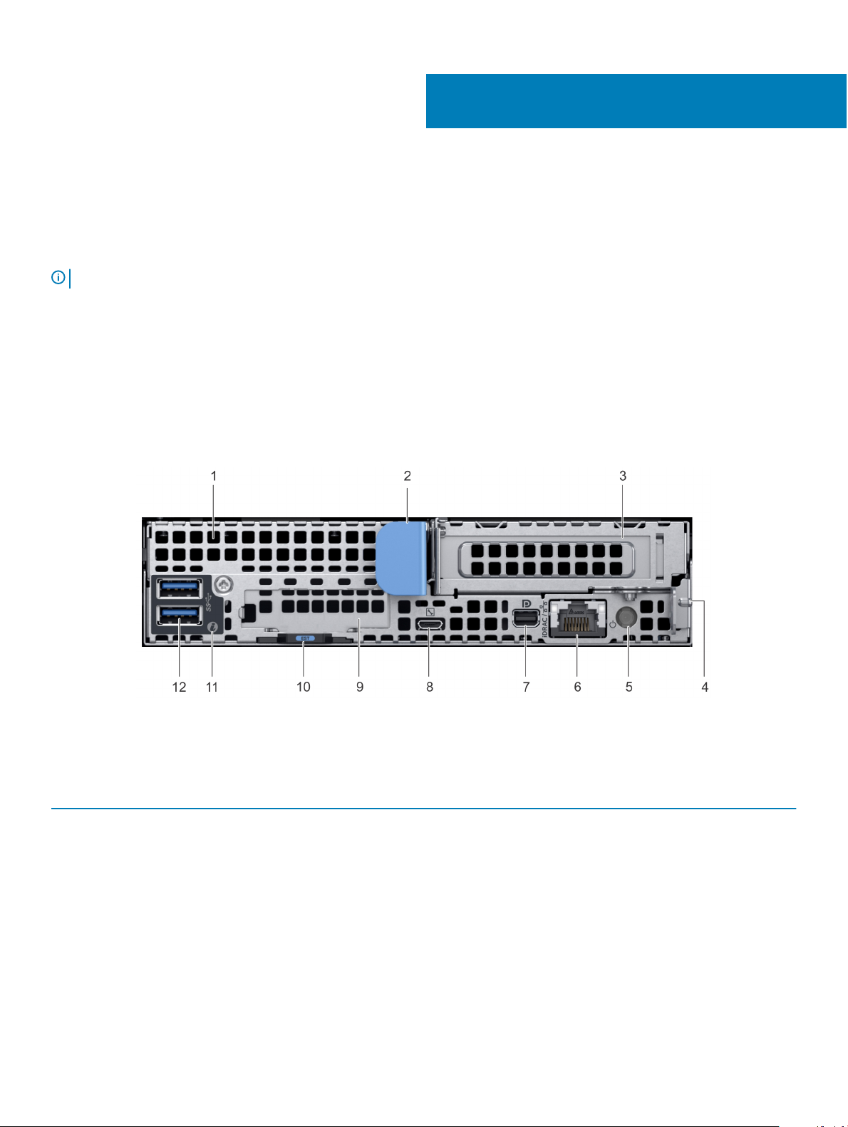
Back view of the XC6420 Series sled
1
Figure 1. Back view of the XC6420 Series sled
Table 1. Back panel features
Item Indicator, button, or connector Icon Description
1 mezzanine card slot N/A
2 sled release handle N/A
3 Low Prole PCIe card slot N/A
4 sled release lock N/A
5 rear power button N/A
Enables you to connect mezzanine expansion cards. For more
information, see Technical specications.
Enables you to remove the sled from the enclosure.
Enables you to connect PCI Express expansion cards. For more
information, see Technical specications.
Enables you to remove the sled from the enclosure.
Enables you to power on the sled while accessing it from the
rear.
XC6420 Series overview 7
Item Indicator, button, or connector Icon Description
6 iDRAC or NIC port Enables you to remotely access iDRAC. For more information,
see the iDRAC User’s Guide at Dell.com/poweredgemanuals.
7 mini display port Enables you to connect a display device to the system. For more
information, see Technical specications.
8 iDRAC Direct micro USB port
9 OCP card slot N/A Enables you to connect Open Compute Project (OCP)
10 EST pull out tab N/A This tab has the unique Express Service Code, Service Tag, and
11 system id indicator The System Identication (ID) LED is available on the back of
12 USB 3.0 port (2)
Enables you to connect a portable device to the sled.
expansion cards. For more information, see Technical
specications.
MAC address labels.
the system. Press the system ID button on the front of the
enclosure to identify a system in a rack.
The USB ports are 9-pin and 3.0-compliant. These ports enable
you to connect USB devices to the system.
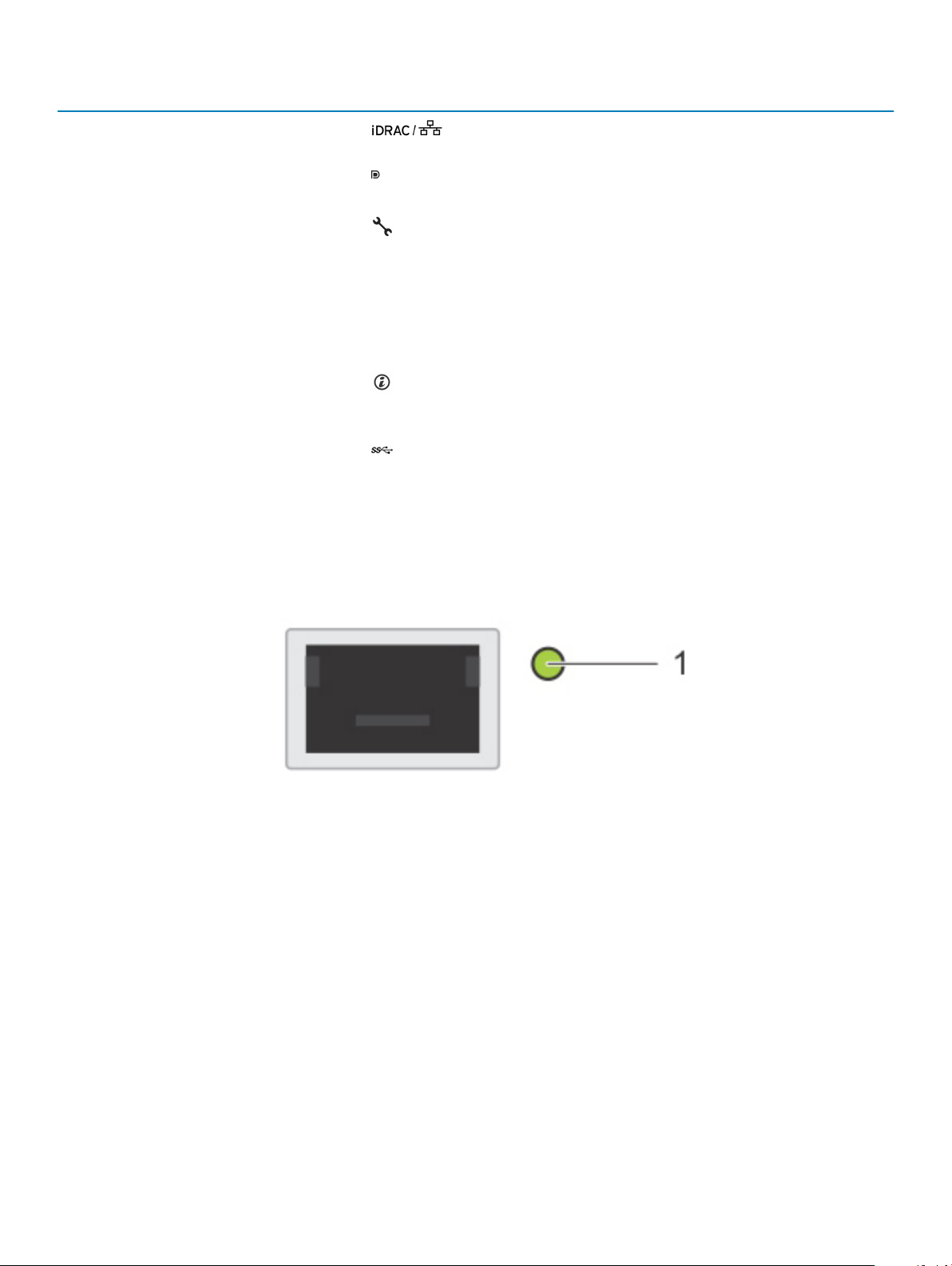
Network ports indicator codes
Figure 2. LAN indicators on the QSFP carrier card
1
Link indicator
8 XC6420 Series overview
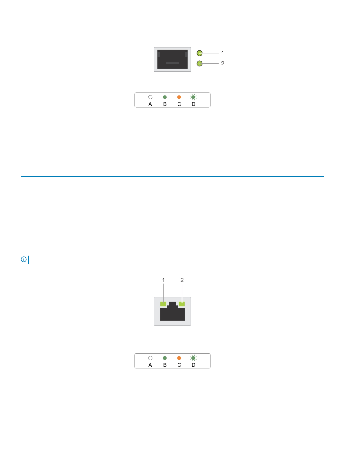
Figure 3. LAN indicators on the QSFP mezzanine card
1 Link indicator 2 Activity indicator
Table 2. QSFP port on mezzanine card indicator codes
Connection State QSFP Upper green LED QSFP Lower green LED
No link/Not Connected O O
InniBand Physical Link - No Logical Link Green O
InniBand Logical Link - No Trac Green Green
InniBand Logical Link - Trac Green Blink
InniBand Physical Link Issue Blink Green
Ethernet Link - No Trac Green Green
Ethernet - Trac Green Blink
NOTE: The LED blink speed varies according to the trac bandwidth.
Figure 4. Ethernet port indicator codes
speed indicator 2 link and activity indicator
1
XC6420 Series overview 9
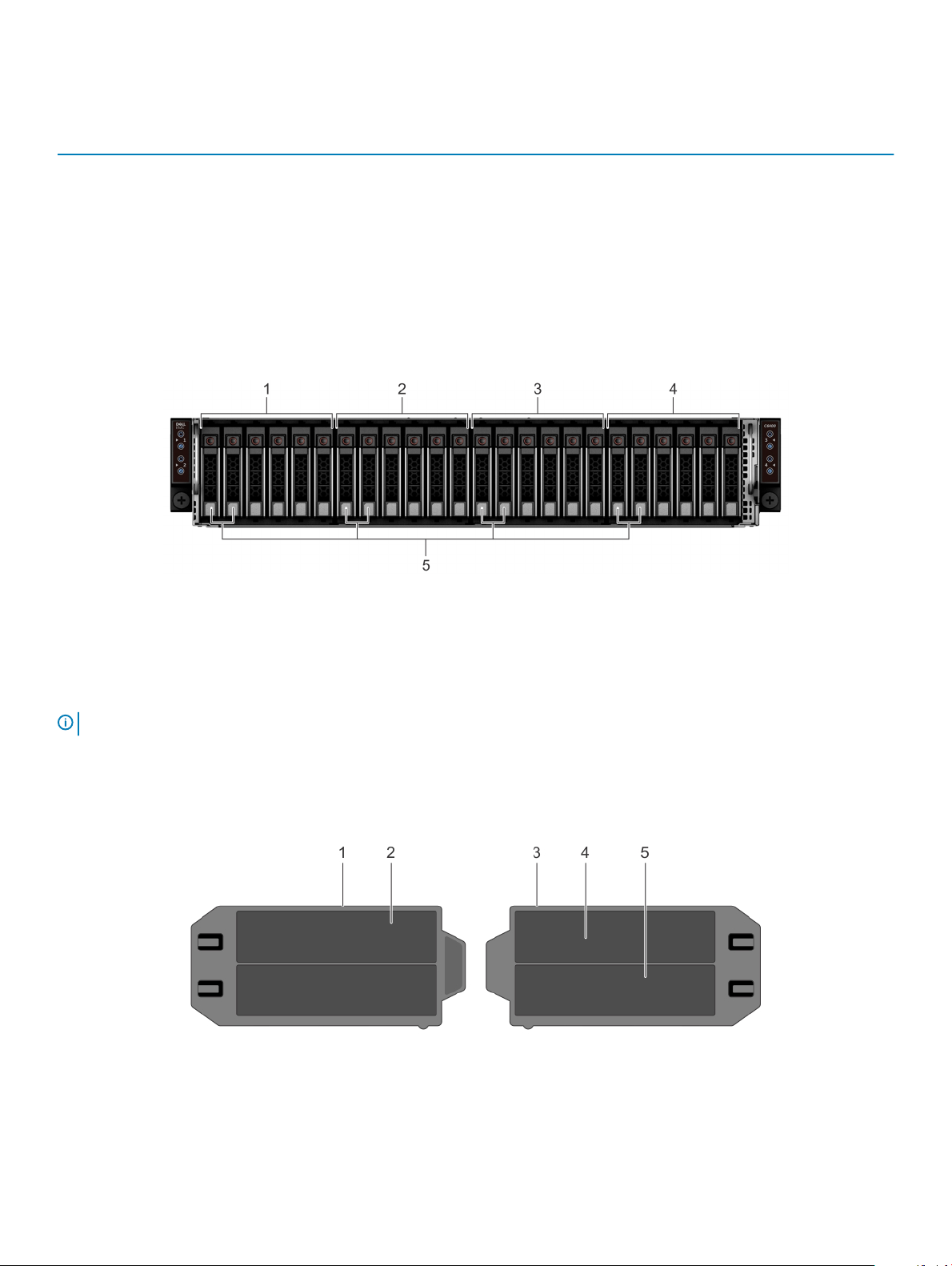
Table 3. Ethernet port indicator codes
Convention Status Condition
A Link and activity indicators are o The NIC is not connected to the network.
B Link indicator is green The NIC is connected to a valid network at its
maximum port speed.
C Link indicator is amber The NIC is connected to a valid network at less than
its maximum port speed.
D Activity indicator is ashing green Network data is being sent or received.
Sled to hard drive mapping
Figure 5. Sled to drive mapping for the enclosure with 24 x 2.5 inch drives
1
drives 0–5 mapped to sled 1 2 drives 6–11 mapped to sled 2
3 drives 12–17 mapped to sled 3 4 drives 18–23 mapped to sled 4
5 (optional) NVMe hard drive location
NOTE: The warranty of the drives are linked to the Service Tag of the corresponding sled.
Locating the Service Tag of your system
Your system is identied by a unique Express Service Code and Service Tag number. The Express Service Code and Service Tag are found
on the back of the sled by pulling out the EST tag. This information is used by Dell EMC to route support calls to the appropriate personnel.
Figure 6. Locating the Service Tag of your system
information tag (top view) 2 Express Service Tag label
1
3 information tag (bottom view) 4 network MAC address information label
10 XC6420 Series overview

5 iDRAC MAC address information label
XC6420 Series overview 11

Documentation resources
Dell EMC documentation is either included with your shipment or available at the Dell website at Dell.com/XCSeriesmanuals.
Dell EMC documentation for Dell EMC iDRAC is available at Dell.com/idracmanuals.
To access the Dell EMC documentation:
1 On the Dell EMC Support page, scroll down to General Support, and then click Servers, Storage & Networking.
2 Click Engineered Solutions and select the documentation you require.
Table 4. Reference documentation for Dell EMC XC6420 Series Hyper-converged Appliance
To learn about... See...
Set up instructions of your Dell EMC XC6420 Series, including the
technical specications
Getting Started Guide
2
Hardware details of your Dell EMC XC6420 Series
How to install your Dell EMC XC6420 Series in a rack
How to deploy your XC6420 Series and set up this solution
Deploying Azure Log Analytics Solution Dell EMC XC Series Azure Log Analytics Solution Deployment Guide
ESXi Best Practices Guide Dell EMC Best Practices for Running VMware ESXi 6.5 or Later
Windows Hyper-V Best Practices Guide Dell EMC XC Series Best Practices for Running Windows Server
Known issues and workarounds Release Notes for XC Series Hyper-Converged Appliances
Support Matrix Dell EMC XC6420 Series Hyper-Converged Appliance Support
Troubleshooting your system Troubleshooting Guide at Dell.com/poweredgemanuals
Installation and Service Manual
Rail Installation Guide
Solutions Guide
Clusters on XC Series Family Appliances
2016 with Hyper-V
Matrix
12 Documentation resources

Technical specications
The technical and environmental specications of your system are outlined in this section.
Topics:
• Dimensions of the XC6420 Series sled
• Chassis weight
• Processor specications
• System battery
• Expansion bus specications
• Memory specications
• Hard drives and storage specications
• Video specications
• Environmental specications
Dimensions of the XC6420 Series sled
3
Figure 7. Dimensions of the XC6420 Series sled
Table 5. Dimensions of the
X Y Z
17.44 mm (6.86 inches) 4.05 mm (1.59 inches) 57.45 mm (22.61 inches)
XC6420 Series sled
Technical specications 13

Chassis weight
Table 6. Chassis weight of the XC6420 Series sleds
System Maximum weight (with all the sleds and drives)
24 x 2.5-inch hard drive systems 41.46 Kg (91.40 lb)
No backplane systems 34.56 Kg (76.19 lb)
Processor specications
The XC6420 Series sled supports up to two Intel Xeon Scalable E5-2600 product family processors in each of the four independent sleds.
Each processor supports up to 28 cores.
System battery
The XC6420 Series sled uses a CR 2032 3V replaceable lithium coin cell battery.
Expansion bus specications
The XC6420 Series sled supports four Generation 3 capable PCIe slots. Two slots are populated with the base conguration.
Table 7. Expansion bus
PCIe Slots Description Form factor
x8 Mezzanine PCIe riser Slot 1: x8 PCIe Gen3 from CPU 1 Custom form factor
x8 + x8 OCP Mezzanine riser
x16 PCIe main riser Slot 4: x16 PCIe Gen3 CPU 1 Standard Low Prole PCIe form factor
x16 buried PCIe riser Slot 5: x16 PCIe Gen3 from CPU 2 Custom form factor
specications
Slot 2: x8 PCIe Gen3 from CPU 1
Slot 3: x8 PCIe Gen3 from CPU 1
Standard Open Compute Project (OCP)
form factor
NOTE: M.2 SATA riser is supported
on the buried riser.
Memory specications
The XC6420 Series sled supports DDR4 registered DIMMs (RDIMMs) and Load Reduced DIMMS (LRDIMMs) including 3D XPoint.
Table 8. Memory
Memory module
sockets
Sixteen 288-pin 2666 MT/s DDR4 RDIMMs
specications
Architecture Memory capacity and
and LRDIMMS with support
for advanced ECC or memory
optimized operation
ranking
• Single rank - 8 GB
• Dual rank - 16 GB
• Dual rank - 64 GB
Minimum RAM Maximum RAM
• 8 GB with a single
processor
• 16 GB with dual
processor
• 512 GB with a single
processor
• 1024 GB with dual
processor
14 Technical specications

Hard drives and storage specications
The XC6420 Series sled supports SAS and SATA hard drives and Solid State Drives (SSDs).
Table 9. Supported drive options for the XC6420 Series sled
Maximum number of drives in the enclosure Maximum number of drives assigned per sled
24 x 2.5-inch drive systems Six SAS or SATA hard drives and SSDs per sled
24 x 2.5-inch drive systems with NVMe The NVMe backplane supports either of these congurations:
• Two NVMe drives and four SAS or SATA hard drives and SSDs
per sled
• Six SAS or SATA hard drives and SSDs per sled
M.2 SATA drive The supported capacity of the M.2 SATA card is 120 GB
microSD card One on each PCIe riser of each sled
Table 10. Supported RAID options with M.2 SATA drives
Options Dual M.2 SATA drives with hardware RAID
Hardware RAID Yes
RAID Mode RAID 1
Number of drives supported 2
Supported CPUs CPU 1 and CPU 2
Video specications
The XC6420 Series sled supports a Matrox G200 integrated graphics card with 16 MB RAM.
Table 11. Supported video resolution options
Resolution Refresh rate (Hz) Color depth (bits)
1024 x 768 60 up to 24
1280 x 800 60 up to 24
1280 x 1024 60 up to 24
1360 x 768 60 up to 24
1440 x 900 60 up to 24
Technical specications 15

Environmental specications
The sections below contains information about the environmental specications of the system.
Temperature specications
Table 12. Temperature specications
Temperature Specications
Storage –40°C to 65°C (–40°F to 149°F)
Continuous operation (for altitude less than 950 m or 3117 ft) 10°C to 35°C (50°F to 95°F) with no direct sunlight on the
equipment.
Maximum temperature gradient (operating and storage) 20°C/h (36°F/h)
NOTE: Some congurations require a lower ambient temperature for more information, see the Standard operating temperature
specications.
Relative humidity specications
Table 13. Relative humidity
Relative humidity Specications
Storage 5% to 95% RH with 33°C (91°F) maximum dew point. Atmosphere
Operating 10% to 80% relative humidity with 29°C (84.2°F)
specications
must be non-condensing at all times.
Maximum vibration specications
Table 14. Maximum vibration
Maximum vibration Specications
Operating 0.26 Grms at 5 Hz to 350 Hz (all operation orientations).
Storage 1.88 Grms at 10 Hz to 500 Hz for 15 min (all six sides tested).
specications
16 Technical specications

Maximum shock specications
Table 15. Maximum shock specications
Maximum shock Specications
Operating 24 executed shock pulses 6 G in the positive and negative x, y, z
axis for up to 11 ms (four pulses on each side of the system).
Storage Six consecutively executed shock pulses of 71 G in the positive and
negative x, y, z axes for up to 2 ms (one pulse on each side of the
system).
Maximum altitude specications
Table 16. Maximum altitude specications
Maximum altitude Specications
Operating 3048 m (10,000 ft)
Storage 12,000 m (39,370 ft)
Operating temperature de-rating specications
Table 17. Operating temperature
Operating temperature de-rating Specications
Up to 35°C (95°F) Maximum temperature is reduced by 1°C/300 m (1°F/547 ft)
above 950 m (3,117 ft).
35°C to 40°C (95°F to 104°F) Maximum temperature is reduced by 1°C/175 m (1°F/319 ft) above
950 m (3,117 ft).
40°C to 45°C (104°F to 113°F) Maximum temperature is reduced by 1°C/125 m (1°F/228
Technical specications 17

Particulate and gaseous contamination specications
Table 18. Particulate contamination specications
Particulate contamination Specications
Air ltration Data center air ltration as dened by ISO
Class 8 per ISO 14644-1 with a 95% upper
condence limit.
NOTE: This condition applies only to data center environments. Air ltration requirements do not apply to IT equipment
designed to be used outside a data center, in environments such as an oce or factory oor.
NOTE: Air entering the data center must have MERV11 or MERV13 ltration.
Conductive dust Air must be free of conductive dust, zinc
whiskers, or other conductive particles.
NOTE: This condition applies to data center and non-data center environments.
Corrosive dust Air must be free of corrosive dust.
Residual dust present in the air must have a deliquescent point less than 60% relative humidity.
NOTE: This condition applies to data center and non-data center environments.
Table 19. Gaseous contamination specications
Gaseous contamination Specications
Copper coupon corrosion rate <300 Å/month per Class G1 as dened by ANSI/ISA71.04-1985.
Silver coupon corrosion rate <200 Å/month as dened by AHSRAE TC9.9.
NOTE: Maximum corrosive contaminant levels measured at ≤50% relative humidity.
Standard operating temperature specications
NOTE
:
1 Not available: Indicates that the conguration is not oered by Dell EMC.
2 Not supported: Indicates that the conguration is not thermally supported.
NOTE: All components including the DIMMs, communication cards, M.2 SATA, and PERC cards can be supported with sucient
thermal margin if the ambient temperature is equal to or below to the maximum continuous operating temperature listed in these
tables with the exception of the Mellanox DP LP card.
18 Technical specications

Table 20. Standard operating temperature specications
Standard operating temperature Specications
Temperature ranges (for altitude less than 950 m or 3117 ft) 10°C to 35°C (50°F to 95°F) with no direct sunlight on the
equipment.
NOTE: Some congurations require a lower ambient temperature. For more information see the following tables.
Table 21. Maximum continuous operating temperature for non-fabric dual processor conguration
TDP (W)
205W
200W
165W
Processor
model
number
8180 CPU1:
8180M CPU1:
8168 CPU1:
6154
6150 CPU1:
Supported
heat sinks
FMM2M |
CPU2:
V2DRD
FMM2M |
CPU2:
V2DRD
FMM2M |
CPU2:
V2DRD
CPU1:
FMM2M |
CPU2:
V2DRD
JYKMM |
CPU2:
V2DRD
Max
DIMM
count per
CPU
CPU1: 6 |
CPU2: 8
CPU1: 6 |
CPU2: 8
CPU1: 6 |
CPU2: 8
CPU1: 6 |
CPU2: 8
CPU1: 8 |
CPU2: 8
24x 2.5”
HDDs
enclosure
Not supported
20x 2.5”
HDDs
enclosure
16x 2.5”
HDDs
enclosure
21°C/
69.8°F
21°C/
69.8°F
21°C/
69.8°F
22°C/
71.6°F
30°C/
86°F
12x 2.5”
HDDs
enclosure
21°C/
69.8°F
21°C/
69.8°F
21°C/
69.8°F
22°C/
71.6°F
30°C/86°F 30°C/86°F 35°C/95°F
8x 2.5”
HDDs
enclosure
21°C/
69.8°F
21°C/
69.8°F
21°C/
69.8°F
22°C/
71.6°F
4x 2.5”
HDDs
enclosure
21°C/
69.8°F
21°C/
69.8°F
21°C/
69.8°F
22°C/
71.6°F
6146 CPU1:
JYKMM |
CPU2:
V2DRD
8176 CPU1:
JYKMM |
CPU2:
V2DRD
8176M CPU1:
JYKMM |
CPU2:
V2DRD
8170M CPU1:
JYKMM |
CPU2:
V2DRD
CPU1: 6 |
CPU2: 8
CPU1: 8 |
CPU2: 8
CPU1: 8 |
CPU2: 8
CPU1: 8 |
CPU2: 8
30°C/
86°F
30°C/
86°F
30°C/
86°F
30°C/
86°F
30°C/86°F 30°C/86°F 35°C/95°F
30°C/86°F 30°C/86°F 35°C/95°F
30°C/86°F 30°C/86°F 35°C/95°F
30°C/86°F 30°C/86°F 35°C/95°F
Technical specications 19

TDP (W)
Processor
model
number
8170 CPU1:
Supported
heat sinks
JYKMM |
CPU2:
V2DRD
Max
DIMM
count per
CPU
CPU1: 8 |
CPU2: 8
24x 2.5”
HDDs
enclosure
20x 2.5”
HDDs
enclosure
16x 2.5”
HDDs
enclosure
30°C/
86°F
12x 2.5”
HDDs
enclosure
30°C/86°F 30°C/86°F 35°C/95°F
8x 2.5”
HDDs
enclosure
4x 2.5”
HDDs
enclosure
155W
150W
CPU1:
6144
6148 CPU1:
6142 CPU1:
6136 CPU1:
8164 CPU1:
8160M CPU1:
FMM2M |
CPU2:
V2DRD
JYKMM |
CPU2:
V2DRD
FMM2M |
CPU2:
V2DRD
JYKMM |
CPU2:
V2DRD
JYKMM |
CPU2:
V2DRD
JYKMM |
CPU2:
V2DRD
CPU1: 6 |
CPU2: 8
CPU1: 8 |
CPU2: 8
CPU1: 8 |
CPU2: 8
CPU1: 8 |
CPU2: 8
CPU1: 8 |
CPU2: 8
CPU1: 8 |
CPU2: 8
Not
supported
30°C/
86°F
30°C/
86°F
30°C/
86°F
30°C/
86°F
30°C/
86°F
30°C/86°F
30°C/86°F
30°C/86°F
30°C/86°F
30°C/86°F
30°C/86°F
30°C/
86°F
30°C/
86°F
30°C/
86°F
30°C/
86°F
30°C/
86°F
30°C/
86°F
30°C/86°F 30°C/86°F 35°C/95°F
30°C/86°F 30°C/86°F 35°C/95°F
30°C/86°F 30°C/86°F 35°C/95°F
30°C/86°F 30°C/86°F 35°C/95°F
30°C/86°F 30°C/86°F 35°C/95°F
30°C/86°F 30°C/86°F 35°C/95°F
8160 CPU1:
JYKMM |
CPU2:
V2DRD
140W
20 Technical specications
6132 CPU1:
JYKMM |
CPU2:
V2DRD
6152 CPU1:
JYKMM |
CPU2:
V2DRD
6140M CPU1:
JYKMM |
CPU2:
V2DRD
6140 CPU1:
JYKMM |
CPU1: 8 |
CPU2: 8
CPU1: 8 |
CPU2: 8
CPU1: 8 |
CPU2: 8
CPU1: 8 |
CPU2: 8
CPU1: 8 |
CPU2: 8
30°C/
86°F
30°C/
86°F
30°C/
86°F
30°C/
86°F
30°C/
86°F
30°C/86°F
30°C/86°F
30°C/86°F
30°C/86°F
30°C/86°F
30°C/
86°F
30°C/
86°F
30°C/
86°F
30°C/
86°F
30°C/
86°F
30°C/86°F 30°C/86°F 35°C/95°F
30°C/86°F 30°C/86°F 35°C/95°F
30°C/86°F 30°C/86°F 35°C/95°F
30°C/86°F 30°C/86°F 35°C/95°F
30°C/86°F 30°C/86°F 35°C/95°F

TDP (W)
Processor
model
number
Supported
heat sinks
CPU2:
V2DRD
Max
DIMM
count per
CPU
24x 2.5”
HDDs
enclosure
20x 2.5”
HDDs
enclosure
16x 2.5”
HDDs
enclosure
12x 2.5”
HDDs
enclosure
8x 2.5”
HDDs
enclosure
4x 2.5”
HDDs
enclosure
130W
125W
115W
CPU1:
6134
6126 CPU1:
8153 CPU1:
6138 CPU1:
6130 CPU1:
6128
JYKMM |
CPU2:
V2DRD
JYKMM |
CPU2:
V2DRD
JYKMM |
CPU2:
V2DRD
JYKMM |
CPU2:
V2DRD
JYKMM |
CPU2:
V2DRD
CPU1:
FMM2M |
CPU2:
V2DRD
CPU1: 8 |
CPU2: 8
CPU1: 8 |
CPU2: 8
CPU1: 8 |
CPU2: 8
CPU1: 8 |
CPU2: 8
CPU1: 8 |
CPU2: 8
CPU1: 6 |
CPU2: 8
30°C/
86°F
30°C/
86°F
30°C/
86°F
30°C/
86°F
30°C/
86°F
30°C/
86°F
30°C/86°F
30°C/86°F
30°C/86°F
30°C/86°F
30°C/86°F
30°C/86°F
35°C/
95°F
35°C/
95°F
35°C/
95°F
35°C/
95°F
35°C/
95°F
35°C/
95°F
35°C/95°F 35°C/95°F 35°C/95°F
35°C/95°F 35°C/95°F 35°C/95°F
35°C/95°F 35°C/95°F 35°C/95°F
35°C/95°F 35°C/95°F 35°C/95°F
35°C/95°F 35°C/95°F 35°C/95°F
35°C/95°F 35°C/95°F 35°C/95°F
105W
85W
5122 CPU1:
FMM2M |
CPU2:
V2DRD
5120 CPU1:
JYKMM |
CPU2:
V2DRD
5118 CPU1:
JYKMM |
CPU2:
V2DRD
5115 CPU1:
JYKMM |
CPU2:
V2DRD
4116 CPU1:
JYKMM |
CPU2:
V2DRD
CPU1: 6 |
CPU2: 8
CPU1: 8 |
CPU2: 8
CPU1: 8 |
CPU2: 8
CPU1: 8 |
CPU2: 8
CPU1: 8 |
CPU2: 8
35°C/
95°F
35°C/
95°F
35°C/
95°F
35°C/
95°F
35°C/
95°F
35°C/95°F
35°C/95°F
35°C/95°F
35°C/95°F
35°C/95°F
35°C/
95°F
35°C/
95°F
35°C/
95°F
35°C/
95°F
35°C/
95°F
35°C/95°F 35°C/95°F 35°C/95°F
35°C/95°F 35°C/95°F 35°C/95°F
35°C/95°F 35°C/95°F 35°C/95°F
35°C/95°F 35°C/95°F 35°C/95°F
35°C/95°F 35°C/95°F 35°C/95°F
Technical specications 21

TDP (W)
Processor
model
number
4114 CPU1:
4112 CPU1:
4110 CPU1:
4108 CPU1:
3106 CPU1:
Supported
heat sinks
JYKMM |
CPU2:
V2DRD
JYKMM |
CPU2:
V2DRD
JYKMM |
CPU2:
V2DRD
JYKMM |
CPU2:
V2DRD
JYKMM |
CPU2:
V2DRD
Max
DIMM
count per
CPU
CPU1: 8 |
CPU2: 8
CPU1: 8 |
CPU2: 8
CPU1: 8 |
CPU2: 8
CPU1: 8 |
CPU2: 8
CPU1: 8 |
CPU2: 8
24x 2.5”
HDDs
enclosure
35°C/
95°F
35°C/
95°F
35°C/
95°F
35°C/
95°F
35°C/
95°F
20x 2.5”
HDDs
enclosure
35°C/95°F
35°C/95°F
35°C/95°F
35°C/95°F
35°C/95°F
16x 2.5”
HDDs
enclosure
35°C/
95°F
35°C/
95°F
35°C/
95°F
35°C/
95°F
35°C/
95°F
12x 2.5”
HDDs
enclosure
35°C/95°F 35°C/95°F 35°C/95°F
35°C/95°F 35°C/95°F 35°C/95°F
35°C/95°F 35°C/95°F 35°C/95°F
35°C/95°F 35°C/95°F 35°C/95°F
35°C/95°F 35°C/95°F 35°C/95°F
8x 2.5”
HDDs
enclosure
4x 2.5”
HDDs
enclosure
3104 CPU1:
70W
4109T
JYKMM |
CPU2:
V2DRD
CPU1:
JYKMM |
CPU2:
V2DRD
CPU1: 8 |
CPU2: 8
CPU1: 8 |
CPU2: 8
35°C/
95°F
35°C/
95°F
35°C/95°F
35°C/95°F
35°C/
95°F
35°C/
95°F
35°C/95°F 35°C/95°F 35°C/95°F
35°C/95°F 35°C/95°F 35°C/95°F
Expanded operating temperature specications
Table 22. Expanded operating temperature
Expanded operating temperature Specications
Continuous operation 5°C to 40°C at 5% to 85% RH with 29°C dew point.
NOTE: Outside the standard operating temperature (10°C to 35°C), the
system can operate continuously in temperatures as low as 5°C and as high as
40°C.
For temperatures between 35°C and 40°C, de-rate maximum allowable temperature by
1°C per 175 m above 950 m (1°F per 319 ft).
≤ 1% of annual operating hours –5°C to 45°C at 5% to 90% RH with 29°C dew point.
22 Technical specications

Expanded operating temperature Specications
NOTE: Outside the standard operating temperature (10°C to 35°C), the
system can operate down to –5°C or up to 45°C for a maximum of 1% of its
annual operating hours.
For temperatures between 40°C and 45°C, de-rate maximum allowable temperature by
1°C per 125 m above 950 m (1°F per 228 ft).
NOTE: When operating in the expanded temperature range, system performance may be impacted.
NOTE: When operating in the expanded temperature range, ambient temperature warnings may be reported in the System Event
Log.
Technical specications 23

Initial system setup and conguration
NOTE: NVMe drive slots are 6, 7, 8, and 9. XC640-4 does not support NVMe drives.
Drive slot numbering is 0 relative for chassis. All NVMe drives are installed in the last slots. Maximum of four NVMe drives are supported.
Topics:
• Setting up your system
• iDRAC conguration
• Methods to download rmware and drivers
Setting up your system
Complete the following steps to set up your system:
About this task
: Do not change any of the factory settings.
NOTE
Steps
1 Unpack the system.
2 Install the system into the rack. For more information about installing the system into the rack, see the Rail Installation Guide at
Dell.com/XCSeriesmanuals.
3 Connect the peripherals to the system.
4 Connect the system to its electrical outlet.
5 Turn the system on by pressing the power button or by using iDRAC.
6 Turn on the attached peripherals.
For more information about setting up your system, see your Getting Started Guide shipped with your system.
4
iDRAC conguration
The Integrated Dell Remote Access Controller (iDRAC) is designed to make system administrators more productive and improve the overall
availability of Dell EMC systems. iDRAC alerts administrators to system issues, helps them perform remote system management, and
reduces the need for physical access to the system.
Options to set up iDRAC IP address
You must congure the initial network settings based on your network infrastructure to enable the communication to and from iDRAC.
You must use the default iDRAC IP address 192.168.0.120 to congure the initial network settings, including setting up DHCP or a static IP
for iDRAC. You can set up the IP address by using one of the following interfaces:
Interfaces
iDRAC Settings
utility
24 Initial system setup and conguration
Document/Section
See Dell Integrated Dell Remote Access Controller User's Guide at Dell.com/idracmanuals

Interfaces Document/Section
Dell Lifecycle
Controller
iDRAC Direct and
Quick Sync 2
(optional)
NOTE: To access iDRAC, ensure that you connect the Ethernet cable to the iDRAC direct port. You can also access iDRAC
through the shared LOM mode, if you have opted for a system that has the shared LOM mode enabled.
See Dell Lifecycle Controller User’s Guide at Dell.com/idracmanuals
See Dell Integrated Dell Remote Access Controller User's Guide at Dell.com/idracmanuals
Log in to iDRAC
You can log in to iDRAC as:
• iDRAC user
• Microsoft Active Directory user
• Lightweight Directory Access Protocol (LDAP) user
If you have opted for secure default access to iDRAC, the iDRAC secure default password is available on the back of the system
Information tag. If you have not opted for secure default access to iDRAC, then the default user name and password are root and
calvin. You can also log in by using Single Sign-On or Smart Card.
NOTE
: You must have the iDRAC credentials to log in to iDRAC.
NOTE: Ensure that you change the default user name and password after setting up the iDRAC IP address.
For more information about logging in to the iDRAC and iDRAC licenses, see the latest Integrated Dell Remote Access Controller User's
Guide at Dell.com/idracmanuals.
You can also access iDRAC by using RACADM. For more information, see the RACADM Command Line Interface Reference Guide at
Dell.com/idracmanuals.
Methods to download rmware and drivers
You can download the rmware and drivers by using any of the following methods:
Table 23. Firmware and drivers
Methods Location
From the Dell Support site Dell.com/support/home
Using Dell Remote Access Controller Lifecycle Controller (iDRAC
with LC)
Downloading drivers and rmware
Dell EMC recommends that you download and install the latest BIOS, drivers, and systems management rmware on your system.
Prerequisite
Ensure that you clear the web browser cache before downloading the drivers and rmware.
Dell.com/idracmanuals
Initial system setup and
conguration 25

Steps
1 Go to Dell.com/support/drivers.
2 In the Drivers & Downloads section, type the Service Tag of your system in the Enter a Service Tag or product ID box, and then click
Submit.
NOTE: If you do not have the Service Tag, select Detect Product to allow the system to automatically detect your Service
Tag, or click View products, and navigate to your product.
3 Click Drivers & Downloads.
The drivers that are applicable to your selection are displayed.
4 Download the drivers to a USB drive, CD, or DVD.
26 Initial system setup and conguration

Pre-operating system management applications
Dell EMC recommends that you do not change any of the factory settings. XC Series settings are congured at the factory.
Topics:
• Options to manage the pre-operating system applications
• System Setup
• Dell Lifecycle Controller
• Boot Manager
• PXE boot
Options to manage the pre-operating system applications
Your system has the following options to manage the pre-operating system applications:
• System Setup
• Dell Lifecycle Controller
• Boot Manager
• Preboot Execution Environment (PXE)
5
System Setup
By using the System Setup screen, you can congure the BIOS settings, iDRAC settings, and device settings of your system.
: Help text for the selected eld is displayed in the graphical browser by default. To view the help text in the text browser,
NOTE
press F1.
You can access system setup by using two methods:
• Standard graphical browser—The browser is enabled by default.
• Text browser—The browser is enabled by using Console Redirection.
Viewing System Setup
To view the System Setup screen, perform the following steps:
1 Turn on, or restart your system.
2 Press F2 immediately after you see the following message:
F2 = System Setup
: If your operating system begins to load before you press F2, wait for the system to nish booting, and then restart
NOTE
your system and try again.
Pre-operating system management applications 27

System Setup details
The System Setup Main Menu screen details are explained as follows:
NOTE: The XC Series system does not support the NVDIMM-N, RAID, or UEFI settings.
Option Description
System BIOS Enables you to congure BIOS settings.
iDRAC Settings Enables you to congure the iDRAC settings.
The iDRAC settings utility is an interface to set up and congure the iDRAC parameters by using UEFI (Unied
Extensible Firmware Interface). You can enable or disable various iDRAC parameters by using the iDRAC settings
utility. For more information about this utility, see Integrated Dell Remote Access Controller User’s Guide at
Dell.com/idracmanuals.
Device Settings Enables you to congure device settings.
System BIOS
You can use the System BIOS screen to edit specic functions such as boot order, system password, setup password, PCIe NVMe RAID
mode, and set the SATA enable or disable USB ports.
: The XC Series system does not support the NVDIMM-N, RAID, or UEFI settings.
NOTE
Viewing System BIOS
To view the System BIOS screen, perform the following steps:
1 Turn on, or restart your system.
2 Press F2 immediately after you see the following message:
F2 = System Setup
NOTE
: If your operating system begins to load before you press F2, wait for the system to nish booting, and then restart
your system and try again.
3 On the System Setup Main Menu screen, click System BIOS.
System BIOS Settings details
: The XC Series system does not support the NVDIMM-N, RAID, or UEFI settings.
NOTE
The System BIOS Settings screen details are explained as follows:
Option
System Information Species information about the system such as the system model name, BIOS version, and Service Tag.
Memory Settings Species information and options related to the installed memory.
Processor Settings Species information and options related to the processor such as speed and cache size.
SATA Settings Species options to enable or disable the integrated SATA controller and ports.
Description
28 Pre-operating system management applications

Option Description
NVMe Settings Species options to change the NVMe settings. If the system contains the NVMe drives that you want to
congure in a RAID array, you must set this eld and the Embedded SATA eld on the SATA Settings menu to
RAID mode. You might also need to change the Boot Mode setting to UEFI. Otherwise, you should set this eld to
Non-RAID mode.
Boot Settings Allows you to set the boot mode — BIOS or UEFI.
Network Settings Species options to manage the UEFI network settings and boot protocols.
Legacy network settings are managed from the Device Settings menu.
Integrated Devices Species options to manage integrated device controllers and ports, species related features and options.
Serial
Communication
System Prole
Settings
System Security Species options to congure the system security settings, such as system password, setup password, Trusted
Redundant OS
Settings
Miscellaneous
Settings
Species options to manage the serial ports, related features and options.
Species options to change the processor power management settings, memory frequency.
Platform Module (TPM) security, and UEFI secure boot. It also manages the power button on the system.
Species the options to congure the Redundant OS settings.
Species options to change the system date and time.
System Information
You can use the System Information screen to view system properties such as Service Tag, system model name, and the BIOS version.
: The XC Series system does not support the NVDIMM-N, RAID, or UEFI settings.
NOTE
Viewing System Information
To view the System Information screen, perform the following steps:
1 Turn on, or restart your system.
2 Press F2 immediately after you see the following message:
F2 = System Setup
NOTE
: If your operating system begins to load before you press F2, wait for the system to nish booting, and then restart
your system and try again.
3 On the System Setup Main Menu screen, click System BIOS.
4 On the System BIOS screen, click System Information.
System Information details
NOTE
: The XC Series system does not support the NVDIMM-N, RAID, or UEFI settings.
The System Information screen details are explained as follows:
Option
System Model
Name
Description
Species the system model name.
Pre-operating system management applications 29

Option Description
System BIOS
Version
System
Management
Engine Version
System Service Tag Species the system Service Tag.
System
Manufacturer
System
Manufacturer
Contact
Information
System CPLD
Version
UEFI Compliance
Version
Species the BIOS version installed on the system.
Species the current version of the Management Engine rmware.
Species the name of the system manufacturer.
Species the contact information of the system manufacturer.
Species the current version of the system complex programmable logic device (CPLD) rmware.
Species the UEFI compliance level of the system rmware.
Memory Settings
You can use the Memory Settings screen to view all the memory settings and enable or disable specic memory functions, such as system
memory testing and node interleaving.
: The XC Series system does not support the NVDIMM-N, RAID, or UEFI settings.
NOTE
Viewing Memory Settings
To view the Memory Settings screen, perform the following steps:
1 Turn on, or restart your system.
2 Press F2 immediately after you see the following message:
F2 = System Setup
NOTE
: If your operating system begins to load before you press F2, wait for the system to nish booting, and then restart
your system and try again.
3 On the System Setup Main Menu screen, click System BIOS.
4 On the System BIOS screen, click Memory Settings.
Memory Settings details
The Memory Settings screen details are explained as follows:
Option
System Memory
Size
System Memory
Type
System Memory
Speed
Description
Species the memory size in the system.
Species the type of memory installed in the system.
Species the system memory speed.
30 Pre-operating system management applications
 Loading...