

Page 1

Service Manual
19” LCD Monitor
DELL E193FPc
THESE DOCUMENTS ARE FOR REPAIR SERVICE INFORMATION ONLY.EVERY REASONABLE EFFOR T
HAS BEEN MADE TO ENSURE THE ACCURACY OF THIS MANUAL; WE CANNOT GUARANTEE THE
ACCURACY OFTHIS INFORMATION AFTER THE DATE OF PUBLICATION AND DISCLAIMS RELIABILITY FOR
CHANGES, ERRORS OR OMISSIONS.
Page 2

Dell E193FPc
Table of contents
Table of contents ---------------------------------------------------------------------------------------------------------------- 02
Revision List -----------------------------------------------------------------------------------------------------------------------------03
Important Safety Notice ------------------------------------------------------------------------------------------------------------04
1. Monitor Specifications ------------------------------------------------------------------------------------------------------05
2. LCD Monitor Description -------------------------------------------------------------------------------------------------- 05
3. Operation instructions-----------------------------------------------------------------------------------------------------------06
3.1 General Instructions---------------------------------------------------------------------------------------------------------06
3.2 Control buttons -----------------------------------------------------------------------------------------------------------------06
3.3 Adjusting the Picture --------------------------------------------------------------------------------------------------------07
4. Input/Output Specification ---------------------------------------------------------------------------------------------------10
4.1 Input Signal Connector -----------------------------------------------------------------------------------------------------10
4.2 Factory Preset Display Modes ----------------------------------------------------------------------------------------- 10
4.3 Power Supply Requirements ---------------------------------------------------------------------------------------- 11
4.4 Panel Specification ----------------------------------------------------------------------------------------------------- 11
5. Block Diagram ----------------------------------------------------------------------------------------------------------------14
5.1 Monitor Exploded View --------------------------------------------------------------------------------------------------------14
5.2 Software Flow Chart ----------------------------------------------------------------------------------------------------15
5.3 Electrical Block Diagram ----------------------------------------------------------------------------------------------17
6. Mechanical Instruction -----------------------------------------------------------------------------------------------------------19
7. Schematic --------------------------------------------------------------------------------------------------------------------------24
6.1 Main Board ---------------------------------------------------------------------------------------------------------------24
6.2 Power Board ---------------------------------------------------------------------------------------------------------------29
8. Layout ----------------------------------------------------------------------------------------------------------------------- 31
7.1 Main Board ---------------------------------------------------------------------------------------------------------------- 31
7.2 Power Board -------------------------------------------------------------------------------------------------------------- 34
7.3 Key Board ----------------------------------------------------------------------------------------------------------------- 35
9. Maintainability-------------------------------------------------------------------------------------------------------------------- 36
8.1 Equipments and Tools Requirement -------------------------------------------------------------------------------- 36
8.2 Trouble Shooting --------------------------------------------------------------------------------------------------------------- 37
8.2.1 Main Board----------------------------------------------------------------------------------------------------------------37
8.2.2 Power/Inverter Board -------------------------------------------------------------------------------------------- 40
8.2.3 Keypad Board ---------------------------------------------------------------------------------------------------- 42
10. White Balance Adjustment ---------------------------------------------------------------------------------------------- 43
11. EDID Content --------------------------------------------------------------------------------------------------------------- 44
12. ISP User Manual ---------------------------------------------------------------------------------------------------------- 45
11.1 Connect ISP Writer preparation action ---------------------------------------------------------------------- 45
11.2 To Use ISP Writer ------------------------------------------------------------------------------------------------ 46
11.3 Executing ISP -------------------------------------------------------------------------------------------------------------50
13. BOM List -----------------------------------------------------------------------------------------------------------------------------51
14. Definition Of Pixel Defects--------------------------------------------------------------------------------------------------------74
2
Page 3

Dell E193FPc
Revision List
Revision Date Revision History TPV model
A00 Mar-15-2004 Initial Release T980KLLHJ8DMN
Change the panel from LG (LPL 19" (B4KB)) to
A01 Jul-20-2005
A02 Nov-22-2005 Add “Important Safety Notice”
A03 Mar.-28-2006 Add “Definition Of Pixel Defects”
A04 April-25-2006
A05 Jun-28-2006
A06 Mar-02-2007 Add Mechanical Instruction in Item 6
SEC (SEC 19" EX1 (LOO))
Add ”Max Brightness measurement” on
Page43
Add new model in Item 13
T980KSLHM8DLN
T980KALHK8DLN
T980KSLHK8DLN
3
Page 4

Dell E193FPc
Important Safety Notice
ANY PERSON ATTEMPTING TO SERVICE THIS CHASSIS MUST FAMILIARIZE HIMSELF WITH THE CHASSIS
AND BE AWARE OF THE NECESSARY SAFETY PRECAUTIONS TO BE USED WHEN SERVICING
ELECTRONIC EQUIPMENT CONTAINING HIGH VOLTAGES.
CAUTION: USE A SEPARATE ISOLATION TRANSFORMER FOR THIS UNIT WHEN SERVICING
REFER TO BACK COVER FOR IMPORTANT SAFETY GUIDELINGS
Important Safety Notice
Proper service and repair is important to the safe, reli able operatio n of all Dell Company** Equipment. The service
procedures recommended by Dell and described in this service manual are effective methods of performing
service operations. Some of these service operations require the use of tools specially designed for the purpose.
The special tools should be used when and as recomm ended.
It is important to note that this manual contains various CAUTIONS and NOTICES which should be carefully read
in order to minimize the risk of personal injury to service personnel. The possibility exists that improper service
methods may damage the equipment. It is also important to unde rst and that the se CAUTIONS and NOTICE S ARE
NOT EXHAUSTIVE. Dell could not possibly know, evaluate and advise the service trade of all conceivable ways in
which service might be done or of the possible hazardous consequences of each way. Consequently, Dell has not
undertaken any such broad evaluation. Accordingly, a servicer who uses a service procedure or tool which is not
recommended by Dell must first satisfy himself thoroughly that neither his safety nor the safe operation of the
equipment will be jeopardized by the service method selected.
* * Hereafter throughout this manual, Dell Comp any will be referred to as Dell.
WARNING
Use of substitute replacement parts, which do not have the same, specified safety characteristics may create
shock, fire, or other hazards.
Under no circumstances should the original desi gn be modified or altered with out written permissi on from Dell. Dell
assumes no liability, express or implied, arising out of any unauthorized modification of design. Servicer assumes
all liability.
FOR PRODUCTS CONTAINING LASER:
DANGER - Invisible laser radiation when open. AVOID DIRECT EXPOSURE TO BEAM.
CAUTION - Use of controls or adjustments or performance of procedure s othe r than those
CAUTION - The use of optical instruments with this product will increase eye hazard.
TO ENSURE THE CONTINUED RELIABILITY OF THIS PRODUCT, USE ONLY ORIGINAL
MANUFACT URER'S REPLACEMENT PARTS, WHICH ARE LISTED WITH THEIR PART
NUMBERS IN THE PARTS LIST SECTION OF THIS SERVICE MANUAL.
Take care during handling the LCD module with backlight unit
- Must mount the module using mounting holes arranged in four corners.
- Do not press on the panel, edge of the frame strongly or electric shock as this will result in damage to the
screen.
- Do not scratch or press on the panel with any sharp objects, such as pen cil or pen as this may result in
damage to the Panel.
- Protect the module from the ESD as it may damage the electronic circuit (C-MOS).
- Make certain that treatment person’s body is grounded throug h wristband.
specified herein may result in hazardous radiation exposure.
- Do not leave the module in high temperature and in areas of high humidity for a long time.
- Avoid contact with water as it may a short circuit within the module.
If the surface of panel becomes dirty, please wipe it off with a soft material. (Cleaning with a dirty or rough cloth
may damage the panel.)
4
Page 5

Dell E193FPc
1. Monitor Specifications
48 cm (19”) a-si TFT Active matrix LCD panel, 0.294mm dot pitch.
16 factory presets, 20 new modes
Vertical refre s h rate 55Hz to 75 Hz
Horizontal frequency 30kHz to 80kHz
Resolutions: 640 x 480 up to 1280 x 1024
Universal power supply designed for worldwide application
CE mark
TCO-99
VESA DPMS compliant
VESA DDC compliant
2. LCD Monitor Description
The LCD MONITOR will contain a main board, PWPC board, keypad board, which house the flat panel control
logic, brightness control logic and DDC.
The power board will provide AC to DC Inverter voltage to drive the backlight of panel and the main board chips
each voltage.
Monitor Block Diagram
CCFL Drive.
Flat Panel and
CCFL backlight
(Include adapter and Inverter
PWPC board
board)
AC-IN
100-240V
Main Board
Keyboard
5
RS232 Connector
For white balance
adjustment in factory
mode
Video signal, DDC
Host Computer
Page 6
Dell E193FPc
3. Operation instructions
3.1 General Instructions
Press the power button to turn the monitor on or off. The other control buttons are located at front pan el of the
monitor. By changing thes e settings, the picture can be adjusted to your personal preferences.
The power cord should be connected.
-
Connect the video cable from the monitor to the video card.
-
Press the power button to turn on the monitor, the power indicator will light up.
-
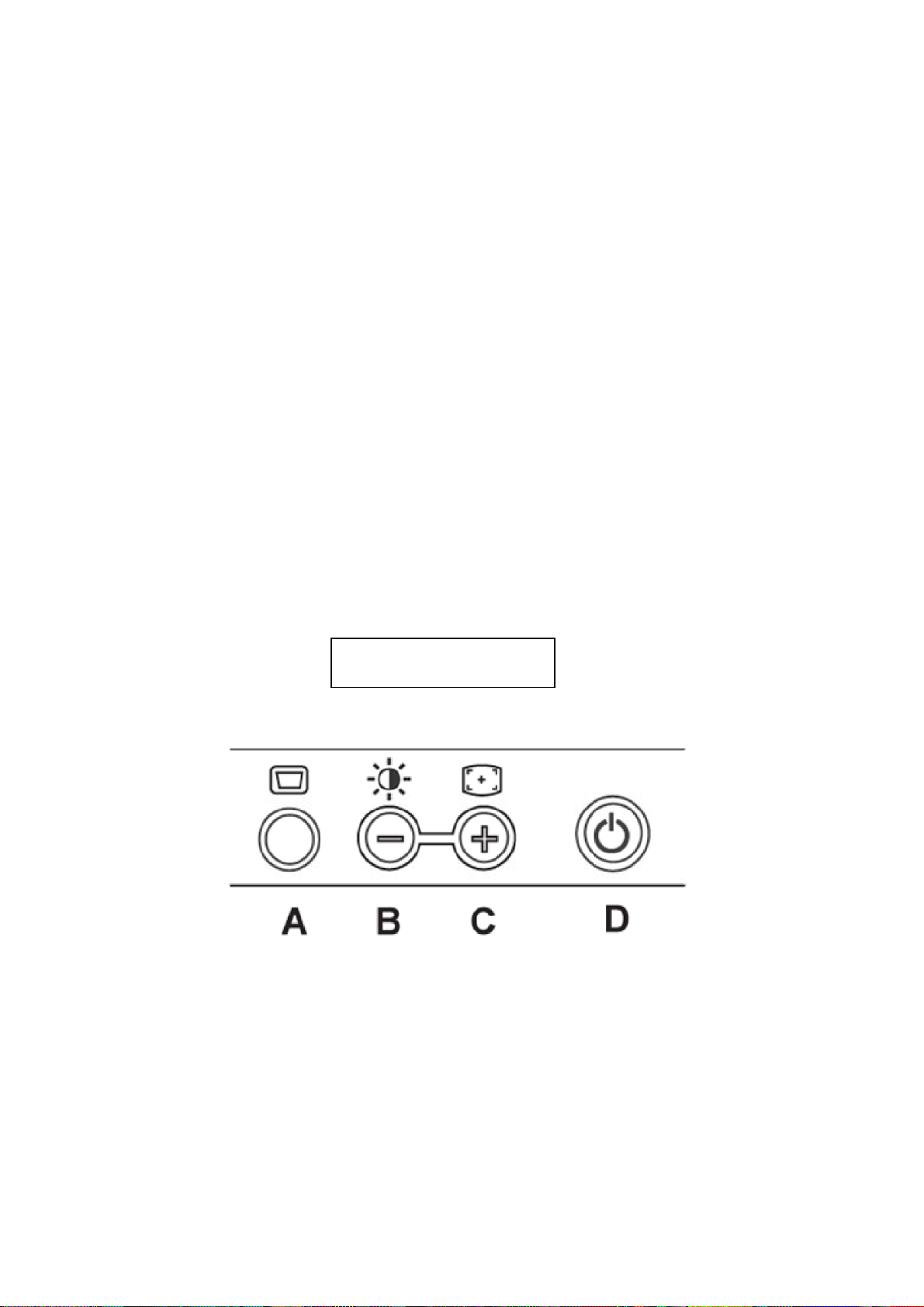
3.2 Control Buttons
Power Button: When pressed, the monitor enters the off mode, and the LED turns blank. Press again to
restore normal status.
Brightness Button: The Brightness Button is used to select the Brightness/Contrast adjust functions.
Press to switch functions or adjust settings.
Auto Adjust Key: The Auto Adjust Key is used to automatically set the H Position, V Position,
Clock and Phase.
Power Indicator:
Green — Power On mode.
Orange — Power Saving mode.
Blank — Power Off Mode.
Control Button
A. Buttons for the OSD menu (On-Screen-display)
B. Brightness Button
C. Auto Adjust Button
D. Power On/Off Button and indicator
6
Page 7
Dell E193FPc
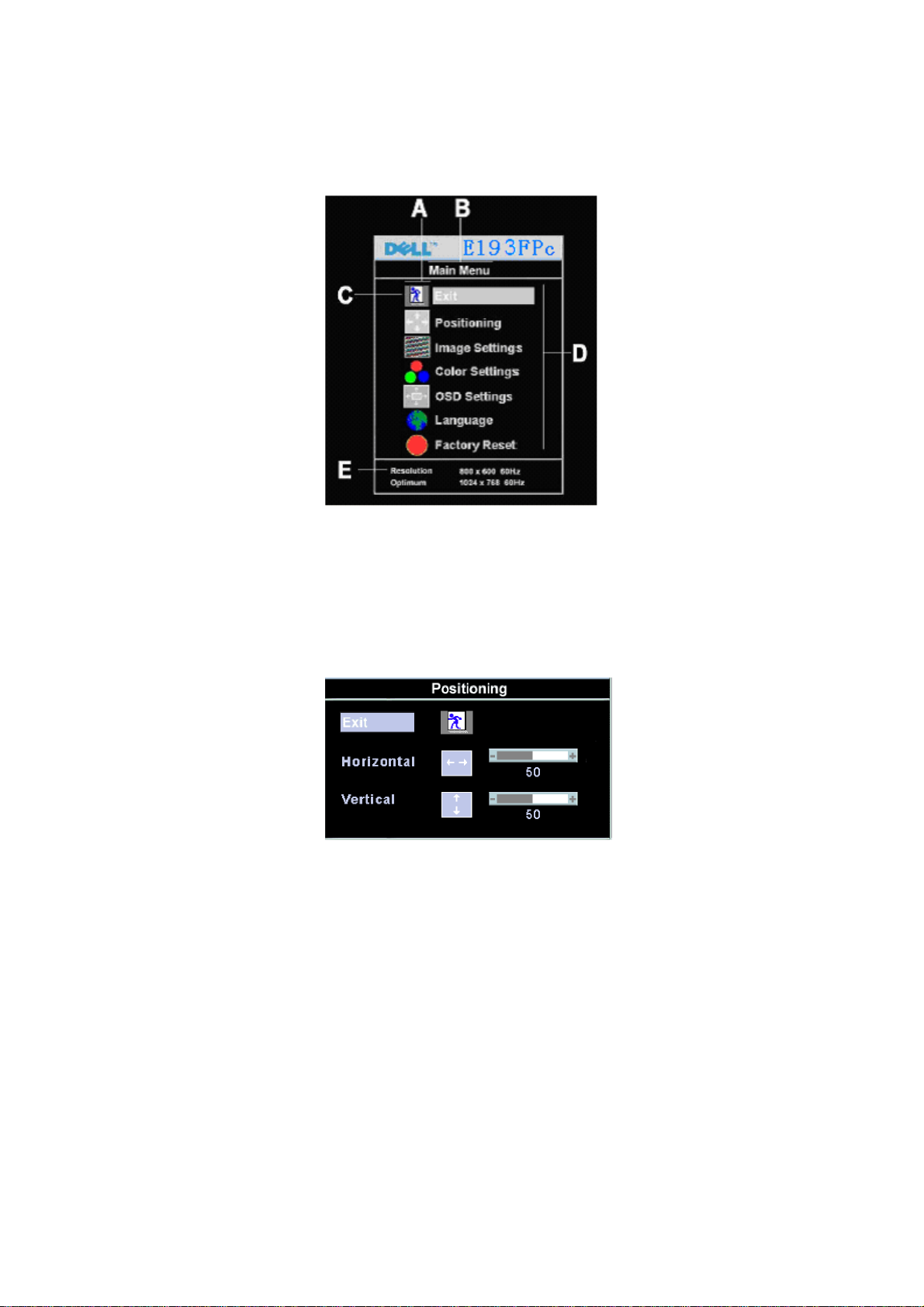
3.3 Adjusting the Picture
To set the OSD menu, perform the following steps:
Briefly press the SELCT / MENU button to activate the OSD menu.
The main menu appears on the screen with icons for the setting functions.
The first symbol (Exit) is highlighted.
Necessary, press the - or + button to mark another icon (e.g. Positioning). Press the SELEC T/MENU button
to select the highlighted icon.
The corresponding setting window (here: Positioning) is displayed.
The first symbol (Exit) is highlighted.
If necessary, press the – or + button to mark the desired icon.
Press the SELECT/MENU button to select the highlighted function.
Press the – or + button to adjust the value for the selected function.
Press the SELECT/MENU button to exit the func tion .
Press the SELECT/MENU button to exit the sub-menu when “Exit” function is highlighted.
All changes are stored automatically.
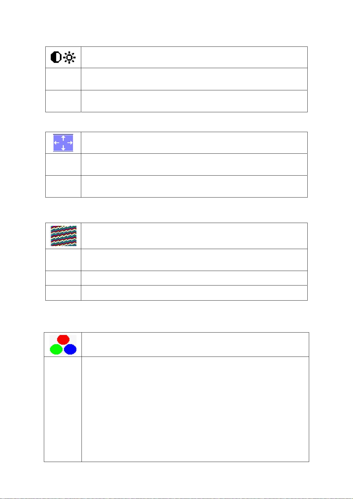
Adjusting the brightness and contrast
7
Page 8
Dell E193FPc
Calling the Brightness / Contrast setting window using Brightness button.
Brightness
Contrast
Setting the brightness of the display
With this function you change the brightness of the background lighting.
Setting the contrast of the display
With this function you modify the contrast o f bright color tones .
Adjusting size and position
H-Position
Calling the Positioning setting window
Adjusting the horizontal position
With this function you move the picture to the left or to the right.
V-Position
Adjusting the vertical position
With this function you move the picture up or down.
Setting Image
Calling the Image setting window
Auto
Adjust
Pixel clock Adjusting the pixel clock
Phase Adjusting the phase
Auto adjust will produce best image automatically, The information of “ Auto
Adjust In Progress” will show;
Setting color temperature and colors
Calling the Color setting window
Selecting the color temperature
The color temperature is measured in K (= Kelvin). You can select from Normal
Preset, Blue Preset, Red Preset to User Preset;
Normal preset = Original color of the LCD display , it’ s 6500K;
Blue preset =5700Kcolour of the LCD display , it’ s 9300K;
Red preset =9300K color of the LCD display, it’s 5700K;
User preset = Setting user-defined colors
In the user preset setting you can change the color ratios of the basic colors (red,
green, blue) as required.
8
Page 9
Dell E193FPc
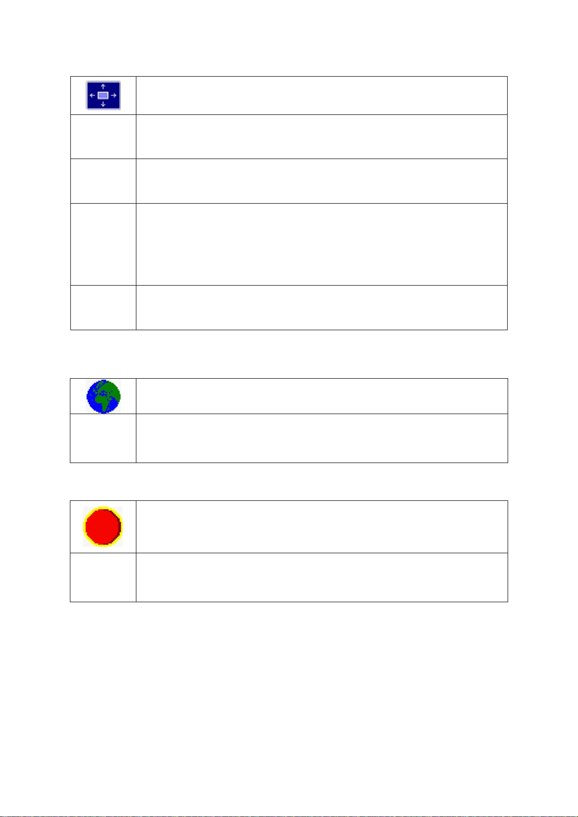
Setting display of the OSD menu
Calling the OSD Set up setting window
Horizontal
Position
Vertical
Position
OSD
Hold
Time
OSD
Lock
Setting the horizontal position of the OSD menu
With this function you move the OSD menu to the left or to the right.
Setting the vertical position of the OSD menu
With this function you move the OSD menu up or down.
Setting the display duration of the OSD menu
With this function you select a value from 0 to 60 seconds.
If the set time expires without a setting being made, the OSD menu is automatically faded
out.
Setting the display of the OSD menu lock or unlock.
With this function you select Y es to lock OSD, NO to unlock it.
Setting Language
Calling the Language setting window
With this function you choose between English (default setting), French, German,
Spani sh and Japanese a s the language for the OSD menu.
Factory Reset
With this function all settings except Language of OSD are reset to the factory settings
without prompting for confirmation.
Activating the factory settings
9
Page 10
Dell E193FPc
4. Input/Output Specification
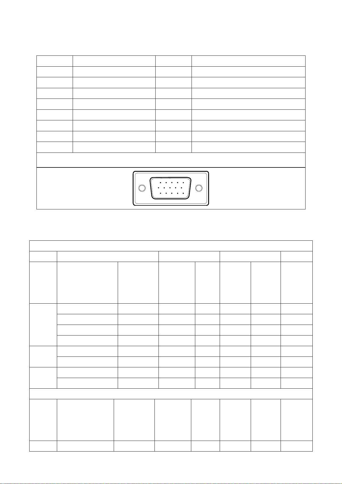
4.1 Input Signal Connector
Pin No. Description Pi N No. Description
1. Red Video 9. +5V
2. Green Video 10. Detector Pin
3. Blue Video 11. RXD
4. TXD 12. DDC-Serial Data
5. DDC-Return 13. H-Sync
6. R-Ground 14. V-Sync
7. G-Ground 15. DDC-Serial Clock
8. B-Ground
VGA Connector layout
15
6
11 15
10
4.2 Factory Preset Display Modes
Horizontal Vertical
Mode Resolution Total
640x480@60Hz 800 x 525 31.469 N 59.940 N 25.175
640x480@75Hz 840 x 500 37.500 N 75.00 N 31.500
VGA
800x600@60Hz 1056 x 628 37.879 P 60.317 P 40.000
800x600@75Hz 1056x625 46.875 P 75.000 P 49.500
1024x768@60Hz 1344x806 48.363 N 60.004 N 65.000
XGA
1024x768@75Hz 1312x800 60.023 P 75.029 P 78.750
VESA MODES
Nominal
Frequency
+/- 0.5kHz
Sync
Polarit
y
Nominal
Freq.
+/- 1 Hz
Sync
Polarity
Nominal
Pixel
Clock
(MHz)
SXGA
Mode Resolution Total
DOS 720x400@70Hz 900 x 449 31.469 N 70.087 P 28.322
1280x1024@60Hz 1688x1066 64.000 P 60.000 P 108.00
1280x1024@75Hz 1688x1066 79.976 P 75.025 P 135.00
IBM MODES
Nominal
Frequency
+/- 0.5kHz
10
Sync
Polarity
Nominal
Sync
Freq.
Polarity
+/- 1 Hz
Nominal
Pixel
Clock
(MHz)
Page 11
Dell E193FPc
4.3 Power Supply Requirements
A/C Line voltage range 100 V ~ 240 V± 10 %
A/C Line frequency range 50 ± 3Hz, 60 ± 3Hz
Input Voltage transients 280 volts AC for 10 sec @40℃
Current 0.6A max. at 100V, 0.35A max. at 240 V
< 60A peak at 240 VAC and cold starting
Peak surge current
< 30A peak a t 120VAC and cold starting
Leakage current < 3.5mA
No advance effects (no loss of information or defect)
Power line surge
with a maximum of 1 half-wave missing per second
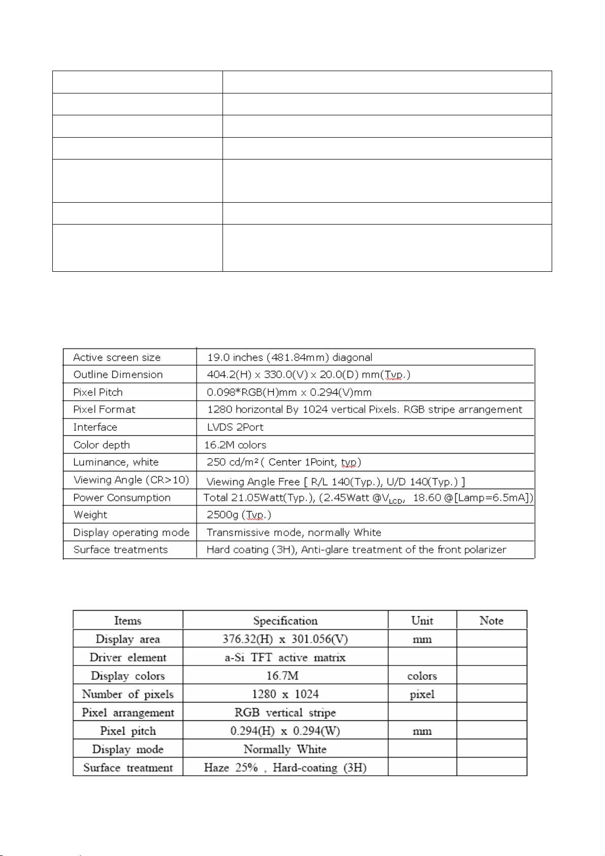
4.4 Panel Specification
4.4.1 Display Characteristics
For LM190E03-B4 model
For LTM190EX-L01 model
11
Page 12
Dell E193FPc
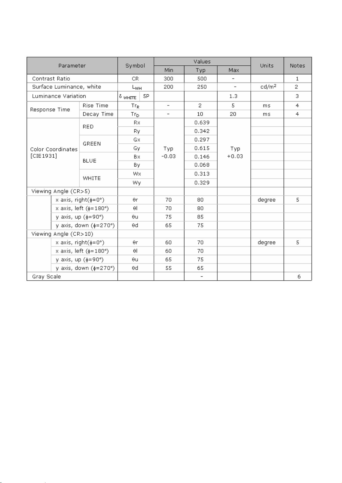
4.4.2 Optical Characteristics
For LM190E03-B4 model
Ta= 25°C, V
=5.0V, fV=60Hz Dclk=54MHz,
LCD
12
Page 13
Dell E193FPc
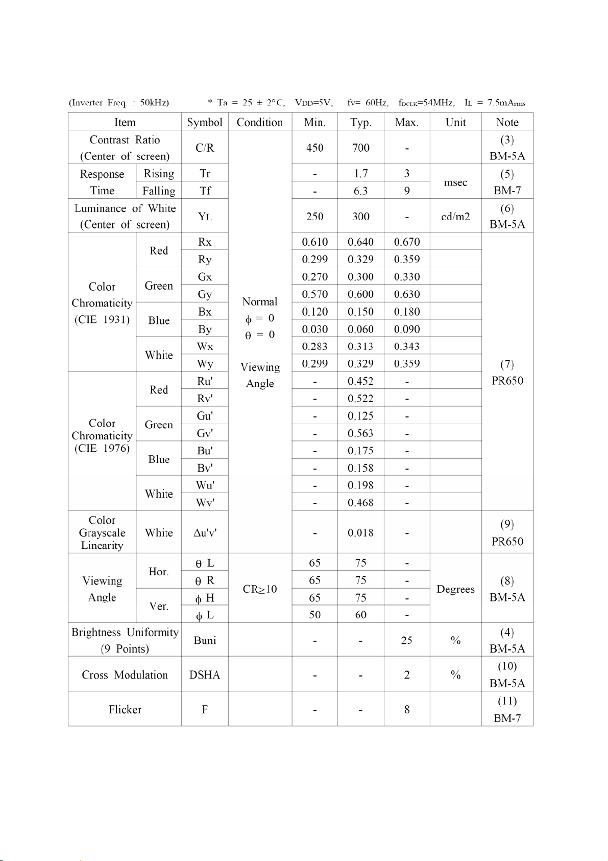
For LTM190EX-L01 model
The optical characteristics are measured under stable conditions as follows:
13
Page 14

Dell E193FPc
5. Block Diagram
5.1 Monitor Exploded View
14
Page 15

Dell E193FPc
5.2 Software Flow Chart
1
2
4
Y
3
N
5
Y
6
7
9
10
Y
N
12
N
N
Y
N
11
13
8
N
18
N
14
19
Y
Y
Y
15
Y
17
15
N
16
Page 16

Dell E193FPc
1) MCU Initializes.
2) Is the EEprom blank?
3) Program the EEprom by default values.
4) Get the PWM value of brightness from EEprom.
5) Is the power key pressed?
6) Clear all global flags.
7) Are the AUTO and SELECT keys pressed?
8) Enter factory mode.
9) Save the power key status into EEprom.
Turn on the LED and set it to green color. Scalar
initializes.
10) In standby mode?
11) Update the lifetime of back light.
12) Check the analog port, are there any signals coming?
13) Does the scalar send out an interrupt request?
14) Wake up the scalar.
15) Are there any signals coming from analog port?
16) Display "No connection Check Signal Cable" message. And go into standby mode after the message
disappears.
17) Program the scalar to be able to show the coming mode.
18) Process the OSD display.
19) Read the keyboard. Is the power key pressed?
16
Page 17
Dell E193FPc
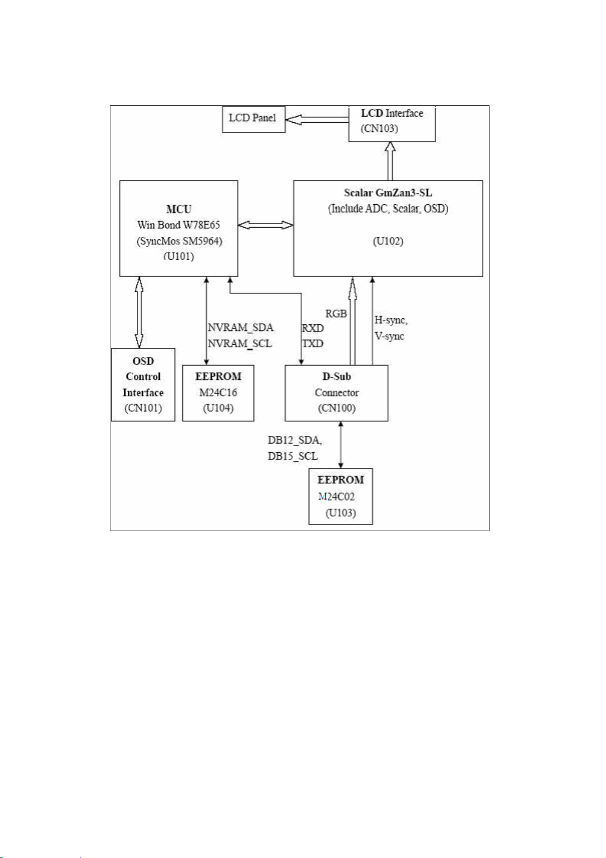
5.3 Electrical Block Diagram
5.3.1 Main Board
17
Page 18

Dell E193FPc
5.3.2 Inverter/Power Board
18
Page 19

Dell E193FPc
6. Mechanical Instruction
Tools: 2 Power screwdrivers (φ=5mm,L=60mm); 1 small cross screwdriver; turnbuckle driver;
Setting: Power screwdriver torque A=11 kgF. Cm; torque B=6 kgF. Cm
Fig Remark
1
Remove stand: Remove the 4 screws
and remove the stand ass’y by torque A
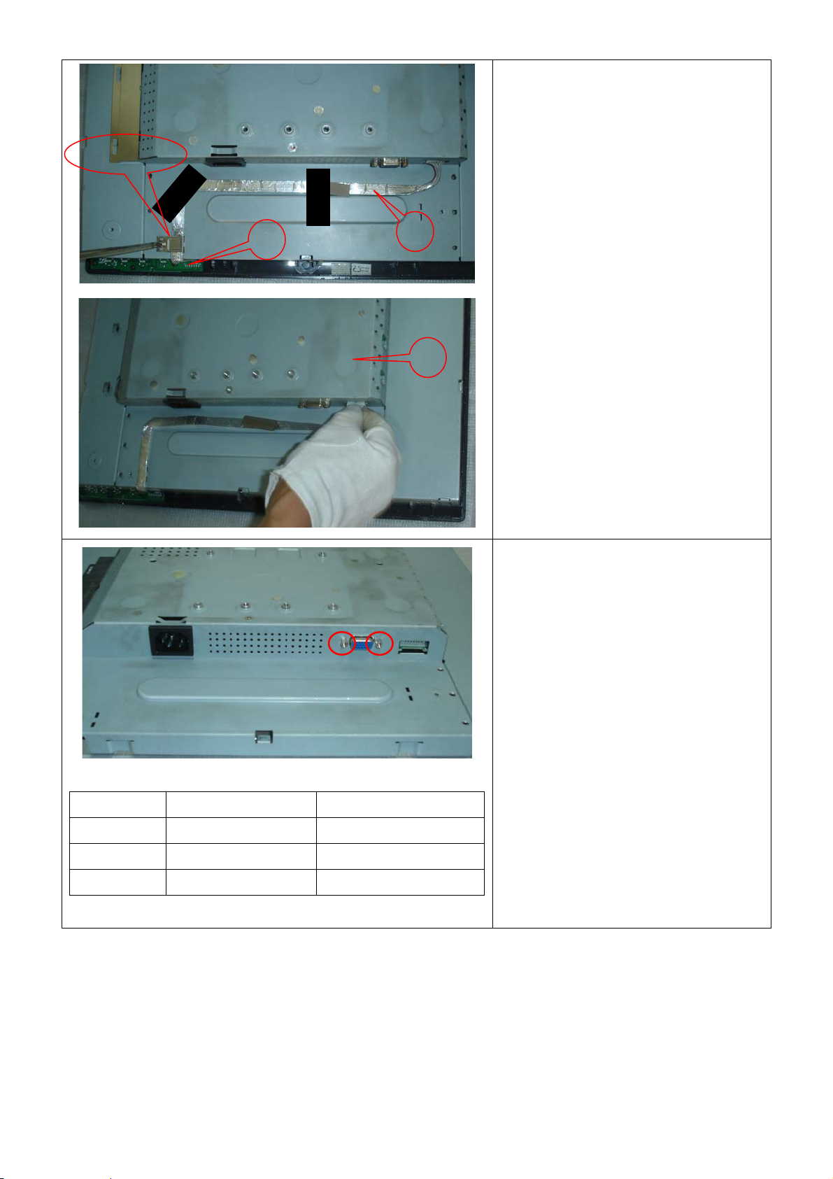
2
3
Remove the rear cover
Pry the monitor up then find out the hooks’
position, use the tool (like the picture or
other card) to insert into the gap of bezel
and rear cover.
Turn over the monitor as the Fig and take
off the rear cover
19
Page 20
Dell E193FPc
Cable hook
5
4
6
Remove bezel:
Disconnect the Key board connector and
remove the bezel
Note: When installing monitor fixes the
cable use Black Ad hesive Tape and screw
the cable hook.
Symbol TPV Part Number Description
4 095G8014 8 21 wire harness
5 KEPC980KED1 Key Board
6 015G8140 2 Main Frame
Remove the small shield:
Remove the screws by Torque B
20
Page 21
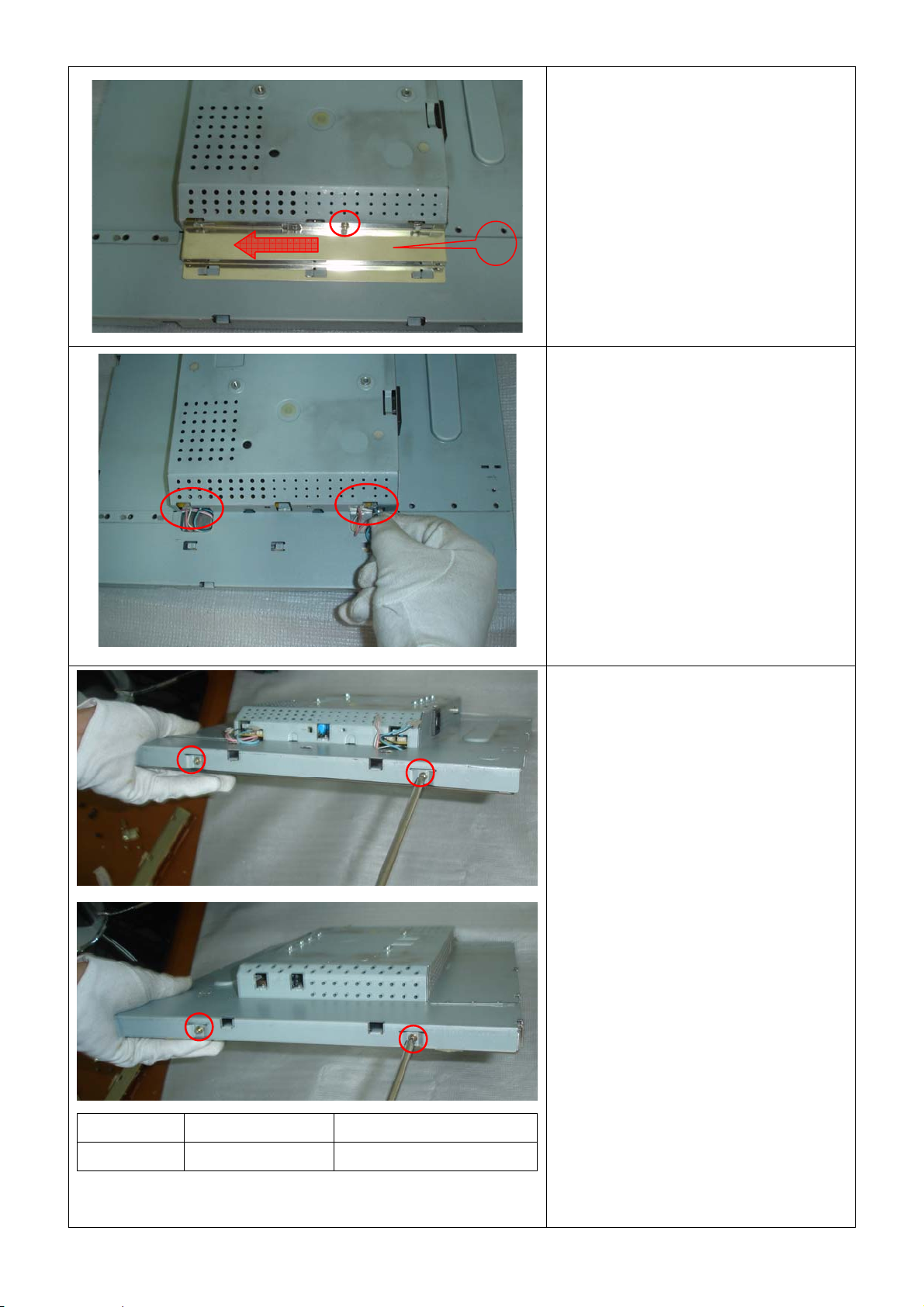
Dell E193FPc
Remove the screw and push the small
shield as the arrowhead direction by
7
Torque B or by manual
Remove the main frame:
Disconnect the back light connectors
Symbol TPV Part Number Description
7 085G 673 1 SHIELD-INVERTER
Remove the four screws and remove the
main frame by manual or torque =
3kgF.Cm
21
Page 22
Dell E193FPc
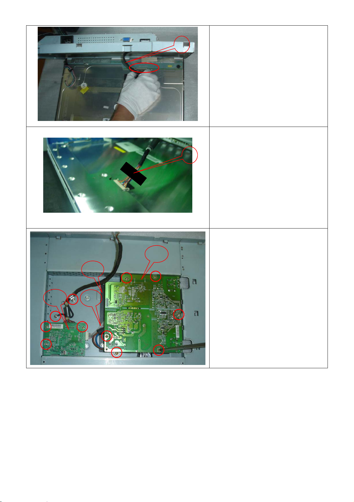
8
Remove the main frame and at the same
time disconnect the LVDS connector
11
13
10
9
When installing monitor. Fix the LVDS by
Black Adhe sive T ape. 10mm should be
kept between the tape and the connect
end.
12
Remove the Power board and main
board:
Remove the eight screws by Torque B
And take off the Power board and main
board.
22
Page 23
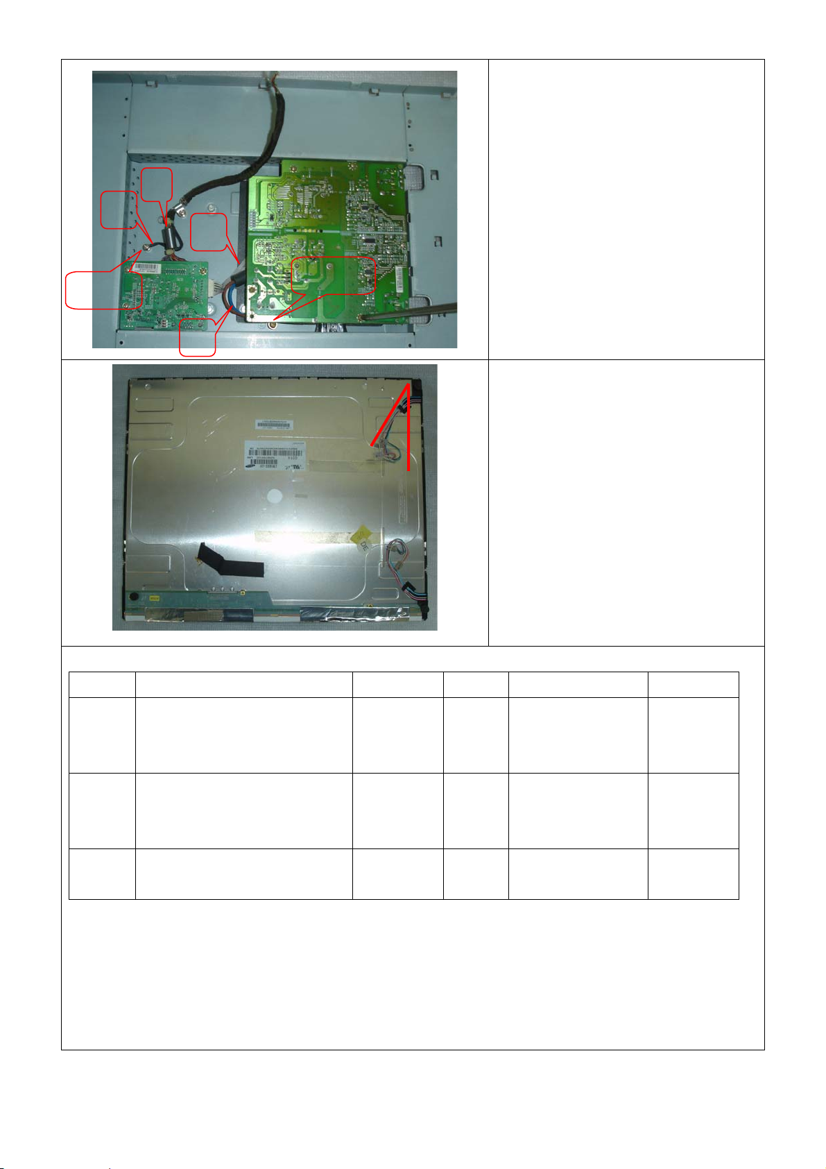
Dell E193FPc
Installing the LVDS cable:
Connect the LVDS cable with MB, and
then fix the cable by screwing the cable
A
Ground
B
D
C
Ground
hook, and the ground end to the
mainframe. Make sure the ground line is
below signal lines.
Line C is power supply for the MB.
Connect the PB and MB directly; the
cable must not touch the pillar of screw.
The end
The angle between CCFL line and vertical
direction should be 30-40 degree.
Symbol TPV Part Number Description Symbol TPV Part Number Description
8 95G8018 30590/95G801 8 30632
95G8018 30576
095G8018 30594
9 052G 1150 C Black
10 095G8014 6 19 Wire
LVDS 11 CBPC980KLLDR
CBPC980KSLDR
CBPC980KALDR
12 PWPC1942LGD1
Adhesive
Tape
13 052G6025 11772 Mylar
Harness
PWPC1942SED1
PWPC1942AUD1
Main Board
Power
Board
23
Page 24
Dell E193FPc
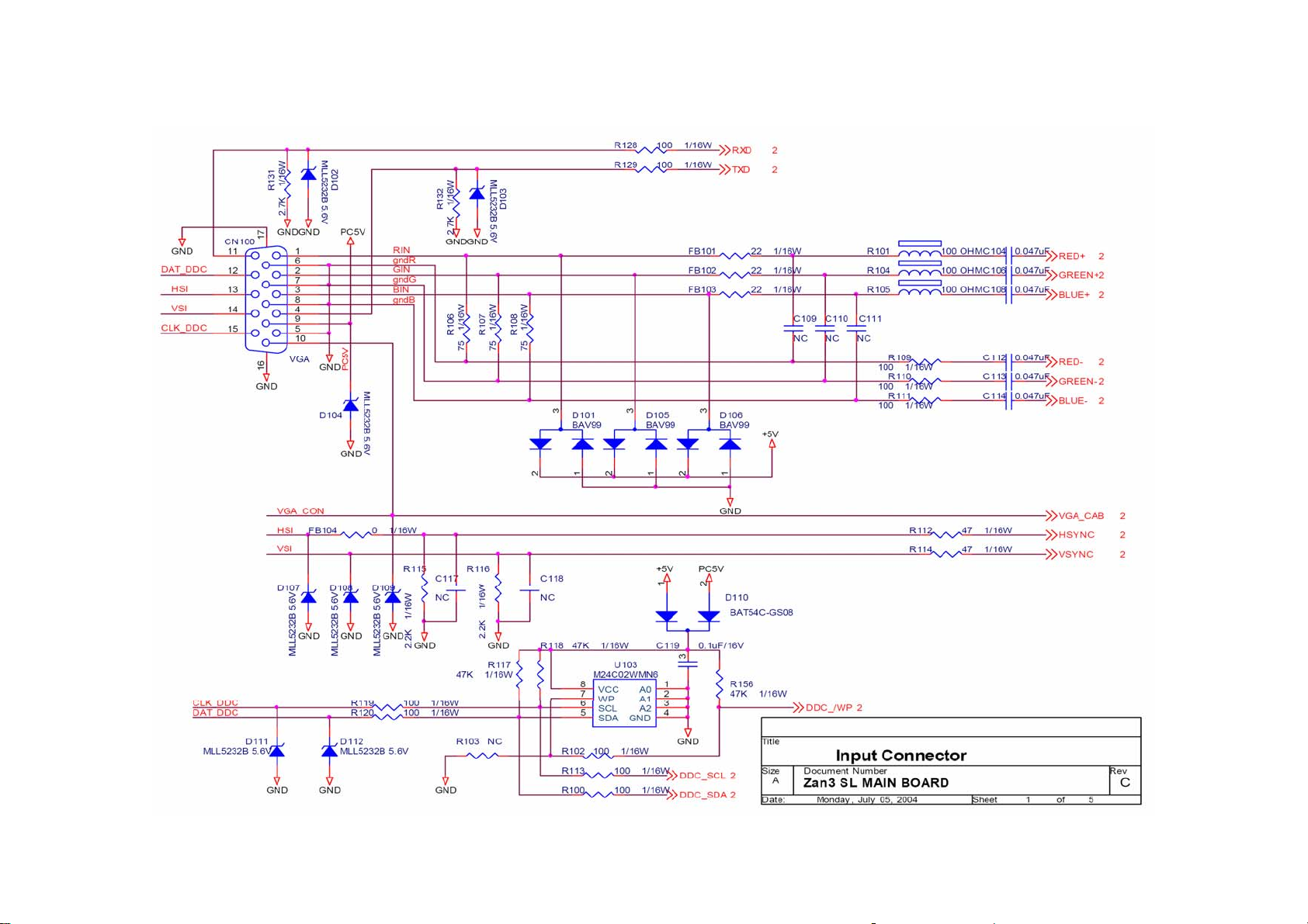
7. Schematic
7.1 Main Board
24
Page 25

Dell E193FPc
25
Page 26

Dell E193FPc
26
Page 27

Dell E193FPc
27
Page 28

Dell E193FPc
28
Page 29

Dell E193FPc
7.2 Power Board
29
Page 30

Dell E193FPc
30
Page 31

8. PCB Layout
8.1 Main Board
Dell E193FPc
31
Page 32

Dell E193FPc
32
Page 33

Dell E193FPc
33
Page 34

8.2 Inverter/Power Board
Dell E193FPc
34
Page 35

8.3 Key Board
Dell E193FPc
35
Page 36

9. Maintainability
9.1 Equipments and Tools Requirement
1. Voltage meter
2. Oscilloscope
3. Pattern Generator
4. LCD Color Analyzer
5. Service Manual
Dell E193FPc
6. User Manual
36
Page 37

9.2 Trouble shooting
9.2.1 Main Board
No display
Measured CN104 pin5 = 5 V?
Measured U101 pin 44= 5V?
Measured U105 pin 2= 3.3V?
OK
Disconnected the Signal cable (Loose the
Signal cable), Is the screen show Block
WRGB color bars?
NG
OK
Dell E193FPc
Check Power board, is there DC level output?
Check U105 pin3=5V, U105 pin2=3.3V?
Is there any shortage or cold solder?
Connected the Signal cable again,
check LED status.
Green
NG
Connected the Signal
cable again Check LED
status.
Green
Check the Wire-Harness from CN101
OK, Wire tight
Check Panel-Power Circuit Block
Check U102 Data-output Block
OK, Panel Power OK
OK, U104 data OK
Orange
OK, Keyboard no stuck
enough
Check Power switch is in Power-on
status, and check if Power switch had
been stuck?
Measured RGB (R112, R114,)
H/V Input at U102 pin 95,96,
Was there have signal?
OK
Measured Crystal X102
OK
Orange
ReplaceU102
Scalar IC
Check
Correspondent
component
short/open
(Protection Diode)
NG
Replace Inverter board and Check
Inverter control relative circuit
Replace U102 (ZAN3XL)
Re-do White balance adjust
OK
Note: 1. If replace “Main-Board”, Please re-do “DDC-content” programmed & “White-Balance”.
2. If replace “Power Board” only , Please re-do “ White-Balance”
37
Page 38

Panel Power Circuit
Check R171 should have response from
0V to 5V when we switch the power
switch from on to off
OK
NG
Dell E193FPc
Check the PPWR panel power relative circuit,
Q105, Q104 In normal operation,
when LED =green, R171 should =5V
If PPWR no-response when the power switch
Turn on and turn off, replace the U102
Measured the Q104 pin 3= 5V?
OK
Inverter Control Relative Circuit
Measured the inverter connector CN104
Pin1 on/off control=3.3V (on)
Pin2 PWM signal control dim 0V-5V
NG, still no screen
NG
Check U102 pin30
OK
NG
Check the BKlt-On relative circuit,
R162, in normal operation, when LED=green,
R162 BKlt-On should=3.3V, If BKlt-On
no-reponse when the power switch turn
on-off, Replace U102
Replace Inverter board to new-one
And check the screen is normal?
NG
Check NO SCREEN APPEAR block
OK
38
Page 39

U102-date Output
Measured DCLK (pin 57 from U102)
DVS, DHS (pin 54,55 from U102)
Is the waveform ok?
DCLK around 48 MHZ, DVS=60.09Hz, DHS around 80
KHz? (Refer to input signal=640x480@60 Hz, and LED is
Green)
Dell E193FPc
NG
Replace ZAN3XL (U102) or
replace Main board.
OK
Check ZAN3/XL (U102)
Signal output (PIN5-14, 106-113,17-26)
NG
If Main Board being replaced, please
do the DDC – content reprogrammed
Is the waveform ok?
OK
OK
39
Page 40

9.2.2 Inverter/Power Board
No Power
Check to CN102 Pin12=12V
Dell E193FPc
Check AC line volt 110V or 220V
Check the voltage of C904(+)
Check start voltage for the pin3 of IC901
OK
OK
OK
OK
NG
NG
Check Interface board
Check AC line
NG
Check F901, bridge rectified circuit
NG
Check R906, R907, IC901
Check the auxiliary voltage Is between 10V-16V
NG
OK
Check D910, D911, ZD904
1) Check IC902, IC903
2) Check Q901, Q902 OVP circuit
40
Page 41

No Backlight
Dell E193FPc
Check C201 (+) =12V
Check U201 pin9=12V voltage of C905(+)
Check the pin1 of U201 have saw tooth wave
OK
Check ON/OFF signal
OK
OK
OK
NG
NG
NG
Change F902
Check D201/Q209/Q210/D202/Q211/Q212
Check Interface board
NG
Change Q201 or Q202
Change U201
Check D201(-), D202(-) have the output of square wave at short time.
NG
OK
Check the resonant wave of pin2 & pin5 for PT201/ PT202
NG
OK
Check the output of PT201/PT202
NG
OK
Check connecter & lamp
CheckQ205/Q207/Q203/Q201 or
/Q206/Q208/Q204/D202
Check Q209/Q210/C213 or Q211/C212/C214
Change PT201/PT202
41
Page 42

9.2.3 Key Board
OSD is unstable or not working
Dell E193FPc
Is Keypad board connecting normally?
OK
Is Button Switch normally?
OK
Is Keypad board normally?
OK
Check main board
NG
Connect Keypad Board
NG
Replace Button Switch
NG
Replace Keypad Board
42
Page 43

Dell E193FPc
10.White balance, Luminance adjustment
Approximately 2 Hours should be allowed for warm up before proceeding White-Balance
adjustment.
Before started adjust white balance, please setting the Chroma-7120 MEM. Channel 3 to 65000K colors, MEM.
Channel 4 to 9300
±20 cd/m
2
, 6500 parameter is x = 313 ±28, y = 329 ±28, Y = 180 ±20 cd/m2, and 5700 parameter is x = 328 ±28, y =
344 ±28, Y = 180 ±20 cd/m
How to setting MEM.channel you can reference to chroma 7120 user guide or simple use “ SC” key and “ NEXT”
key to modify xyY value and use “ID” key to modify the TEXT description Following is the procedure to do
white-balance adjust
Press MENU and AUT O-ADJUST button during press Power button will activate the factory mode,
0
K colors, MEM. Channel 9 to 57000K (our 9300 parameter is x = 283 ±28 y =297±28, Y =175
2
)
Gain adjustment:
Move cursor to “-Factory Setting-” and press MENU key to enter this sub-menu;
Move cursor to “ Factory” and press MENU key;
Move cursor to “ Auto Level” and press MENU key to adjust Gain and Of fs et autom atically;
0
a. Adjust sRGB (6500
K) color-temperature
1. Switch the chroma-7120 to RGB-mode (with press “MODE” button)
2. Switch the MEM.channel to Channel 3 (with up or down arrow on chroma 7120)
3. The LCD-indicator on chroma 7120 will show x = 313 ±28, y = 329 ±28, Y = 180 ±20 cd/m
4. Adjust the RED on OSD window until chroma 7120 indicator reached the value R=100
5. Adjust the GREEN on OSD, until chroma 7120 indicator reached G=100
6. Adjust the BLUE on OSD, until chroma 7120 indicator reached B=100
7. Repeat above procedure (item 5,6,7) until chroma 7120 RGB value meet the tolerance =100±2
0
b. Adjust Color1 (9300
K) color-temperature
8. Switch the chroma-7120 to RGB-mode (with press “MODE” button)
2
9. Switch the MEM.channel to Channel 4 ( with up or down arrow on chroma 7120 )
10. The LCD-indicator on chroma 7120 will show x = 283 ±28 y =297±28, Y = 175 ±20 cd/m
1 1. Adjust the RED on OSD window until chroma 7120 indicator reached the value R=100
12. Adjust the GREEN on OSD, until chroma 7120 indicator reached G=100
13. Adjust the BLUE on OSD, until chroma 7120 indicator reached B=100
14. Repeat above procedure (item 5,6,7) until chroma 7120 RGB value meet the tolerance =100±2
0
c. Adjust Color2 (5700
K) color-temperature
15. Switch the chroma-7120 to RGB-mode (with press “MODE” button)
16. Switch the MEM.channel to Channel 9 (with up or down arrow on chroma 7120)
17. The LCD-indicator on chroma 7120 will show x = 328 ±28, y = 344 ±28, Y = 180 ±20 cd/m
18. Adjust the RED on OS D window until chroma 7120 indicator reached the value R=100
19. Adjust the GREEN on OSD, until chroma 7120 indicator reached G=100
20. Adjust the BLUE on OS D, until chroma 7120 indicator reached B=100
43
2
2
Page 44

Dell E193FPc
21. Repeat above procedure (item 5,6,7) until chroma 7120 RGB value meet the tolerance =100±2
22. Move cursor to “ Exit/Save” sub-menu and press MENU key to save adjust value and exit.
Turn the POWER-button off to on to quit from factory mode.
Max Brightness measurement:
a. Switch to the full white pattern, in user mode main menu:
1. Set <Color Settings> Red, Green, and Blue to the max.
2. Set <Brightness> Brightness, Contrast to the max.
b. The Minimum brightness is 200cd/m2 ±20.
11. EDID Content
00 01 02 03 04 05 06 07 08 09 10 11 12 13 14 15
0: 00 FF FF FF FF FF FF 00 10 AC 0E 70 34 33 32 31
16: 2E 0E 01 03 68 26 1E 78 2E CE 50 A3 54 4C 99 26
32: 0F 50 54 A5 4B 00 71 4F 81 80 01 01 01 01 01 01
48: 01 01 01 01 01 01 30 2A 00 98 51 00 2A 40 30 70
64: 13 00 78 2D 11 00 00 1E 00 00 00 FF 00 36 34 31
80: 38 30 33 39 46 31 32 33 34 0A 00 00 00 FC 00 44
96: 45 4C 4C 20 45 31 39 33 46 50 63 0A 00 00 00 FD
112: 00 38 4C 1E 51 0E 00 0A 20 20 20 20 20 20 00 3B
Note: Byte 0C, 0D, 0E, 0F means Serial No. Byte 10, 11 means manufacture time. Byte
7F means checksum
44
Page 45

Dell E193FPc
12. ISP (In System Program) User Manual
12.1 Connect ISP Writer preparation action
Connect RXD and TXD of PC to RXD (P3.0) and TXD (P3.1) of CPU through RS-232.
a. There are two ways to entering Reboot Mode. The settings for Reboot Mode is as follow
z Both P2.6 P2.7 are LOW and RESET pin is HIGHT.
z P4.3 is LOW and RESET pin is HIGHT.
45
Page 46

Dell E193FPc
12.2 To Use ISP WRITER (take E153FP for example)
Press the “–“ key at front bezel and plug the AC power cord in, then the MCU enter ISP mode;
a. You will enter the window as follow after executing the ispwriter.exe file.
46
Page 47

Dell E193FPc
b. Click the “Select Chip” button, and choose the type you’re going to program.
47
Page 48

Dell E193FPc
c. Click the “Select Bank0” button and selecting a file which a binary Format required.
48
Page 49

d. Select the communication Setting: Port Name
e. Click the “ConNect” button.
Dell E193FPc
49
Page 50

f. Click “Program all” to start programming.
12.3. Executing ISP
Dell E193FPc
a. “Program All” button that will execute erase and program and verify. Then you can get the window as
follow, and cli ck “OK” to complete ISP process.
b. Complete the ISP process, click“exit LD”button to reset monitor.
50
Page 51

13. BOM List
T980KLLHJ8DMN
Location Part NO Description
M1L 330 4128 SCREW M3X4
CBPC980KLLDR CONVERSION BOARD
KEPC980KED1 KEY BOARD
PWPC1942LGD1 POWER BOARD
11L6036 1 SPACER SUPPORT SCC-24
12L 394 1 FOOT PORON
15G8140 2 MAINFRAME LG
15L5689 3 A GROUND CLAMP
23L3178700 1A LOGO
26G 800700 5B BARCODE
33L4669 GV C POWER BUTTON
33L4817 GV T KEYPAD BUTTON
Dell E193FPc
34L1495AY2 T BEZEL
34L1496 Y2 T REAR COVER
40G 191700 1 ID LABEL
40G 581700 3A CARTON LABEL
44L3231 15507 EVA WASHER
44L3923 1 EPS
44L3923 2 EPS
44L3923 3EPE EPE
44L3923700 1A CARTON
45L 88626DE3 PE BAG FOR MONITOR
52L 1186 SMALL TAPE
52L 1207 A ALUMINIUM TAPE
52L6022 1500 SMALL TAPE
52L6025 11828 MYLAR
85L 673 1 SHIELD-INVERTER
85L6096 1 DIP-EMI
89L1738GAA 16 SIGNAL CABLE
89L401A18NHRA POWER CORD
95G8018 30594 WIRE HARNESS (TD1?
M1G2940 10225 SCREW
M1L 130 6225 SCREW M3X6
M1L1730 6128 SCREW M3x6
M1L1740 6128 SCREW
Q1L 330 8 47 SCREW 3X8mm
705L 980 87DL2 CN901 ASS'Y
51
Page 52

705L980KB34083 19" COVER ASS'Y
750LLG90E03 4 LPL 19" (B4KB) PANEL
40L 457624 1B CPU LABEL
AIC980KSLDR MAIN BOARD
40L 45762412B CBPC LABEL
C122 67L309V220 3 22UF +-20% 16V
C129 67L309V220 3 22UF +-20% 16V
C136 67L309V220 3 22UF +-20% 16V
C140 67L309V220 3 22UF +-20% 16V
C143 67L309V220 3 22UF +-20% 16V
C158 67L309V101 3 100UF 16V
C162 67L309V101 3 100UF 16V
C165 67L309V470 3 47UF 16V 85C
C166 67L309V470 3 47UF 16V 85C
C169 67L309V229 7 2.2UF +-20% 50V
Dell E193FPc
C171 67L309V470 3 47UF 16V 85C
C172 67L309V220 3 22UF +-20% 16V
CN100 88L 35315F H D-SUB 15PIN
CN101 33L3802 8H WAFER 8P RIGHT ANGLE PI
CN103 33L8027 24 H CONN W TO B12P*2 P*2.0
CN104 33L8013 6 H 6P PLUG R/A
U101A 56L1125137LD5 W78E65P-40 BY WINBOND
X101 93G 22 53 H 14.31818MHZ/30PF/49US
X102 93G 22 53 H 14.31818MHZ/30PF/49US
715L1280 E PCB
C104 65L0603473 32 CHIP 0.047UF 50V X7R
C106 65L0603473 32 CHIP 0.047UF 50V X7R
C108 65L0603473 32 CHIP 0.047UF 50V X7R
C112 65L0603473 32 CHIP 0.047UF 50V X7R
C113 65L0603473 32 CHIP 0.047UF 50V X7R
C114 65L0603473 32 CHIP 0.047UF 50V X7R
C119 65L0603104 12 0.1UF +-10% 16V X7R
C123 65L0603104 12 0.1UF +-10% 16V X7R
C124 65L0603104 12 0.1UF +-10% 16V X7R
C125 65L0603104 12 0.1UF +-10% 16V X7R
C126 65L0603104 12 0.1UF +-10% 16V X7R
C127 65L0603104 12 0.1UF +-10% 16V X7R
C128 65L0603104 12 0.1UF +-10% 16V X7R
C130 65L0603104 12 0.1UF +-10% 16V X7R
C131 65L0603104 12 0.1UF +-10% 16V X7R
52
Page 53

Dell E193FPc
C132 65L0603104 12 0.1UF +-10% 16V X7R
C133 65L0603104 12 0.1UF +-10% 16V X7R
C134 65L0603104 12 0.1UF +-10% 16V X7R
C135 65L0603104 12 0.1UF +-10% 16V X7R
C137 65L0603104 12 0.1UF +-10% 16V X7R
C138 65L0603104 12 0.1UF +-10% 16V X7R
C139 65L0603104 12 0.1UF +-10% 16V X7R
C141 65L0603104 12 0.1UF +-10% 16V X7R
C142 65L0603104 12 0.1UF +-10% 16V X7R
C144 65L0603104 12 0.1UF +-10% 16V X7R
C145 65L0603104 12 0.1UF +-10% 16V X7R
C147 65L0603220 31 CHIP 22PF 50V NPO
C148 65L0603220 31 CHIP 22PF 50V NPO
C149 65L0603104 12 0.1UF +-10% 16V X7R
C150 65L0603104 12 0.1UF +-10% 16V X7R
C152 65L0603102 32 1000PF +-10% 50V X7R
C153 65L0603102 32 1000PF +-10% 50V X7R
C154 65L0603102 32 1000PF +-10% 50V X7R
C155 65L0603102 32 1000PF +-10% 50V X7R
C156 65L0603102 32 1000PF +-10% 50V X7R
C157 65L0603102 32 1000PF +-10% 50V X7R
C159 65L0603104 12 0.1UF +-10% 16V X7R
C163 65L0603104 12 0.1UF +-10% 16V X7R
C164 65L0603104 12 0.1UF +-10% 16V X7R
C167 65L0603104 12 0.1UF +-10% 16V X7R
C168 65L0603104 12 0.1UF +-10% 16V X7R
C173 65L0603104 12 0.1UF +-10% 16V X7R
C174 65L0603104 12 0.1UF +-10% 16V X7R
C175 65L0603104 12 0.1UF +-10% 16V X7R
C176 65L0603220 31 CHIP 22PF 50V NPO
C177 65L0603220 31 CHIP 22PF 50V NPO
D101 93G 6433P BAV99
D102 93L 39146 LL5232B SMT
D103 93L 39146 LL5232B SMT
D104 93L 39146 LL5232B SMT
D105 93G 6433P BAV99
D106 93G 6433P BAV99
D107 93L 39146 LL5232B SMT
D108 93L 39146 LL5232B SMT
D109 93L 39146 LL5232B SMT
53
Page 54

Dell E193FPc
D110 93L 64 42 P BAV70 SOT-23
D111 93L 39146 LL5232B SMT
D112 93L 39146 LL5232B SMT
FB101 61L0603220 CHIPR 22 OHM+-5% 1/10W
FB102 61L0603220 CHIPR 22 OHM+-5% 1/10W
FB103 61L0603220 CHIPR 22 OHM+-5% 1/10W
FB104 61L0603000 CHIPR 0OHM +-5% 1/10W
FB105 71L 56K121 M CHIP BEAD
L101 71L 56K121 M CHIP BEAD
L102 71L 56K121 M CHIP BEAD
L103 71L 56K121 M CHIP BEAD
L104 71L 56K121 M CHIP BEAD
L105 71L 56K121 M CHIP BEAD
L106 71L 56K121 M CHIP BEAD
Q101 57G 417 4 PMBS3904/PHILIPS-SMT(04
Q102 57G 417 4 PMBS3904/PHILIPS-SMT(04
Q104 57L 763 1 A03401 SOT23 BY AOS(A1)
Q105 57G 417 4 PMBS3904/PHILIPS-SMT(04
R101 71L 59Q101 CHIP BEAD 100 OHM
R102 61L0603101 CHIPR 1 00 OHM +-5% 1/10
R104 71L 59Q101 CHIP BEAD 100 OHM
R105 71L 59Q101 CHIP BEAD 100 OHM
R106 61L0603750 9F 75OHM 1% 1/10W
R107 61L0603750 9F 75OHM 1% 1/10W
R108 61L0603750 9F 75OHM 1% 1/10W
R109 61L0603101 CHIPR 1 00 OHM +-5% 1/10
R110 61L0603101 CHIPR 100 OHM +-5% 1/10
R111 61L0603101 CHIPR 100 OHM +-5% 1/10
R112 61L0603470 CHIPR 47 OHM +-5% 1/10W
R114 61L0603470 CHIPR 47 OHM +-5% 1/10W
R115 61L0603222 CHIPR 2.2K OHM+-5% 1/10
R116 61L0603222 CHIPR 2.2K OHM+-5% 1/10
R117 61L0603472 CHIPR 4.7K OHM +-5% 1/1
R118 61L0603472 CHIPR 4.7K OHM +-5% 1/1
R119 61L0603101 CHIPR 100 OHM +-5% 1/10
R120 61L0603101 CHIPR 1 00 OHM +-5% 1/10
R122 61L0603472 CHIPR 4.7K OHM +-5% 1/1
R123 61L0603472 CHIPR 4.7K OHM +-5% 1/1
R125 61L0603101 CHIPR 1 00 OHM +-5% 1/10
R126 61L0603101 CHIPR 1 00 OHM +-5% 1/10
54
Page 55

Dell E193FPc
R127 61L0603472 CHIPR 4.7K OHM +-5% 1/1
R128 61L0603101 CHIPR 1 00 OHM +-5% 1/10
R129 61L0603101 CHIPR 1 00 OHM +-5% 1/10
R130 61L0603101 CHIPR 1 00 OHM +-5% 1/10
R131 61L0603272 CHIP 2.7K OHM 1/10W
R132 61L0603272 CHIP 2.7K OHM 1/10W
R133 61L0603472 CHIPR 4.7K OHM +-5% 1/1
R134 61L0603472 CHIPR 4.7K OHM +-5% 1/1
R135 61L0603472 CHIPR 4.7K OHM +-5% 1/1
R137 61L0603101 CHIPR 1 00 OHM +-5% 1/10
R139 61L0603101 CHIPR 1 00 OHM +-5% 1/10
R141 61L0603101 CHIPR 1 00 OHM +-5% 1/10
R142 61L0603000 CHIPR 0OHM +-5% 1/10W
R143 61L0603472 CHIPR 4.7K OHM +-5% 1/1
R144 61L0603472 CHIPR 4.7K OHM +-5% 1/1
R146 61L0603000 CHIPR 0OHM +-5% 1/10W
R147 61L0603472 CHIPR 4.7K OHM +-5% 1/1
R148 61L0603472 CHIPR 4.7K OHM +-5% 1/1
R154 61L0603472 CHIPR 4.7K OHM +-5% 1/1
R155 61L0603472 CHIPR 4.7K OHM +-5% 1/1
R156 61L0603473 CHIP 47K OHM 1/10W
R157 61L0603221 CHIPR 220 OHM+-5% 1/10W
R158 61L0603221 CHIPR 220 OHM+-5% 1/10W
R159 61L0603221 CHIPR 220 OHM+-5% 1/10W
R160 61L0603221 CHIPR 220 OHM+-5% 1/10W
R161 61L0603472 CHIPR 4.7K OHM +-5% 1/1
R162 61L0603472 CHIPR 4.7K OHM +-5% 1/1
R163 61L0603472 CHIPR 4.7K OHM +-5% 1/1
R164 61L0603102 CHIPR 1K O HM +-5% 1/10W
R165 61L0603102 CHIPR 1K O HM +-5% 1/10W
R168 61L0603472 CHIPR 4.7K OHM +-5% 1/1
R169 61L0603000 CHIPR 0OHM +-5% 1/10W
R171 61L0603104 CHIPR 100K OHM +-5% 1/1
R172 61L1206331 CHIP 330OHM 5% 1/4W
R173 61L0603472 CHIPR 4.7K OHM +-5% 1/1
RP103 61L 125472 8 CHIP AR 8P4R 4.7K OHM+-
U101 87L 202 44 PLCC SMT CONN PD41C-441
U102 56L 562 58 GMZAN3/SL (AC)
U103 56L1133 34 M24C02-WMN6T SMT
U104 56L1133 56 M24C16-WMN6T/W SO-8
55
Page 56

Dell E193FPc
U105 56L 585 4 AIC1117-33CY
U106 56G 563 27 AIC1117A-18CY SOT -223
715L1408 1 PCB
CN101 95G8014 8 21 WIRE HARNESS
LED1 81L 12 1A GP LED
R101 61L 60210152T 100OHM +- 5% 1/6W
SW101 77L 600 4 HJ TACT SWITCH TSPE-1
SW102 77L 600 4 HJ TACT SWITCH TSPE-1
SW103 77L 600 4 HJ TACT SWITCH TSPE-1
SW104 77L 600 4 HJ TACT SWITCH TSPE-1
PW1942LGD1SMT POWER BOARD FOR SMT
40L 45762420A ID LABEL
71L 55 2 A FERRITE BEAD 6.5*5*1.7
705L 560 57 DL D910/D911 ASS'Y
705L 560 61 06 R903 ASS'Y
705L 780 57 DL Q903 ASS'Y
705L 780 61 07 R917 ASS'Y
705L1742 HL BD901/C903/IC901 ASS'Y
C213 63L210J1842A2 PMS 0.18UF 250V
C214 63L210J1842A2 PMS 0.18UF 250V
C226 65L 3J2206ET 22PF 5% 3KV TDK
C227 65L 3J2206ET 22PF 5% 3KV TDK
C228 65L 3J2206ET 22PF 5% 3KV TDK
C229 65L 3J2206ET 22PF 5% 3KV TDK
C901 65L305M2222EM 2200PF+-20% 250VAC/400V
C902 65L305M2222EM 2200PF+-20% 250VAC/400V
C904 67L215S10115K 100UF 450V
C913 65L306M3322F2 3300PF +-20% 400VAC Y1
C922 67L215L102 4N KY25VB1000M-L 12.5*20
C923 67L215C102 3H EC LESR 1000UF16V HERME
CN901 33G8029 4A PLUG
CON102 95G8014 6 19 WIRE HARNESS
CON201 33L8021 2D AC CONN.2P R/A 87210-0236
CON202 33L8021 2D AC CONN.2P R/A 87210-0236
CON203 33L8021 2D AC CONN.2P R/A 87210-0236
CON204 33L8021 2D AC CONN.2P R/A 87210-0236
IC902 56L 139 3B PC123 Y82
L201 73G 253139 HA CHOKE COIL
L202 73G 253139 HA CHOKE COIL
L203 73L 174 30YSA FILTER
56
Page 57

Dell E193FPc
L204 73L 174 30YSA FILTER
L902 73L 174 40 LS LINE FILTER
L903 73L 253 91 LS CHOKE BY LI SHIN
L904 73L 253 91 LS CHOKE BY LI SHIN
NR901 61L 58120 WT NTCR 12OHM 20% 2A SCK-1
PT201 80LL15T 7YSG X'FMR
PT202 80LL15T 7YSG X'FMR
Q209 57G 761 6 2SC5706-P-E
Q210 57G 761 6 2SC5706-P-E
Q211 57G 761 6 2SC5706-P-E
Q212 57G 761 6 2SC5706-P-E
T901 80LL17T 2 T X'FMR
PW1942LGD1AI POWER BOARD FOR AI
C202 65L0805104 22 0.1UF +-10% 25V X7R 080
C203 65L0805105 22 CHIP 1UF 25V X7R 0805
C204 65L0805104 22 0.1UF +-10% 25V X7R 080
C205 65L0805104 22 0.1UF +-10% 25V X7R 080
C206 65L0805104 22 0.1UF +-10% 25V X7R 080
C208 65L0805331 31 CHIP 330pF 50V NPO
C209 65L0805105 22 CHIP 1UF 25V X7R 0805
C210 65L0805105 22 CHIP 1UF 25V X7R 0805
C211 65L0805105 22 CHIP 1UF 25V X7R 0805
C212 65L0805105 22 CHIP 1UF 25V X7R 0805
C219 65L0805105 22 CHIP 1UF 25V X7R 0805
C220 65L0805105 22 CHIP 1UF 25V X7R 0805
C221 65L0805474 22 CHIP 0.47UF 25V X7R 080
C222 65L0805474 22 CHIP 0.47UF 25V X7R 080
C230 65L0805102 32 CHIP 1000P 50VX7R 0805
C231 65L0805102 32 CHIP 1000P 50VX7R 0805
C907 65L0805104 32 CHIP 0.1UF 50V X7R
C908 65L0805104 32 CHIP 0.1UF 50V X7R
C909 65L0805104 32 CHIP 0.1UF 50V X7R
C910 65L0805102 32 CHIP 1000P 50VX7R 0805
C911 65L0805471 21 CHIP 470PF 25V NPO
C926 65L0805104 32 CHIP 0.1UF 50V X7R
C927 65L0805104 32 CHIP 0.1UF 50V X7R
C930 65L0805102 32 CHIP 1000P 50VX7R 0805
C931 65L0805102 32 CHIP 1000P 50VX7R 0805
D201 93G3004 2 SR34 PAN JIT
D202 93G2004 2A SM240A DO-214AC
57
Page 58

Dell E193FPc
D203 93G 39S 3 T BZT52-C11
D204 93G 39S 3 T BZT52-C11
F201 61L1206000 CHIPR 0 OHM +-5% 1/4W
Q201 57G 760 5B PDTC144WK SOT346
Q202 57G 760 4B PDTA144WK SOT346
Q203 57L 763 3 AO4411 SO-8 BY AOS SMT
Q204 57L 763 3 AO4411 SO-8 BY AOS SMT
Q205 57G 417 4 PMBS3904/PHILIPS-SMT(04
Q206 57G 417 4 PMBS3904/PHILIPS-SMT(04
Q207 57G 417 6 PMBS3906/PHILIPS-SMT(06
Q208 57G 417 6 PMBS3906/PHILIPS-SMT(06
R202 61L0603512 CHIP 5.1K OHM 1/10W
R203 61L0603512 CHIP 5.1K OHM 1/10W
R204 61L0603103 CHIPR 10K OHM +-5% 1/10
R205 61L0603683 CHIP 68K OHM 1/10W
R206 61L0603683 CHIP 68K OHM 1/10W
R208 61L0603472 CHIPR 4.7K OHM +-5% 1/1
R209 61L0603472 CHIPR 4.7K OHM +-5% 1/1
R210 61L0603123 CHIP 12K OHM 1/10W
R211 61L0603123 CHIP 12K OHM 1/10W
R212 61L0603392 CHIP 3.9K OHM 1/10W
R213 61L0603392 CHIP 3.9K OHM 1/10W
R214 61L0603392 CHIP 3.9K OHM 1/10W
R215 61L0603392 CHIP 3.9K OHM 1/10W
R216 61L0603221 CHIPR 220 OHM+-5% 1/10W
R217 61L0603221 CHIPR 220 OHM+-5% 1/10W
R218 61L0603471 CHIPR 470 OHM+-5% 1/10W
R219 61L0603471 CHIPR 470 OHM+-5% 1/10W
R220 61L0603153 CHIPR 1 5KOHM+-5% 1/10W
R221 61L0603153 CHIPR 1 5KOHM+-5% 1/10W
R222 61L0603123 CHIP 12K OHM 1/10W
R223 61L0603123 CHIP 12K OHM 1/10W
R234 61L0603621 CHIPR 620 OHM+-5% 1/10W
R235 61L0603621 CHIPR 620 OHM+-5% 1/10W
R236 61L0603471 CHIPR 470 OHM+-5% 1/10W
R237 61L0603471 CHIPR 470 OHM+-5% 1/10W
R238 61L0603123 CHIP 12K OHM 1/10W
R239 61L0603123 CHIP 12K OHM 1/10W
R240 61L0603513 CHIP 51K OHM 1/10W
R241 61L0603513 CHIP 51K OHM 1/10W
58
Page 59

Dell E193FPc
R901 61L1206105 CHIP 1MOHM 5% 1/4W
R902 61L1206105 CHIP 1MOHM 5% 1/4W
R908 61L1206519 CHIPR 5.1 OHM +-5% 1/4W
R909 61L1206472 CHIP 4.7KOHM 5% 1/4W
R910 61L1206472 CHIP 4.7KOHM 5% 1/4W
R911 61L1206472 CHIP 4.7KOHM 5% 1/4W
R912 61L1206101 CHIP 100 OHM 5% 1/4W
R913 61L1206103 CHIP 10KOHM 5% 1/4W
R914 61L1206243 CHIP 24K OHM 5% 1/4W
R928 61L1206102 CHIP 1K OHM 5% 1/4W
U201 56L 608 1 TL1451ACD
ZD901 93G 39S 23 T GLZ22B
ZD904 93L 39S 19 T PTZ7.5B
715L1283 4 PCB
C201 67L215C1514HT LOW ESR 150UF 25V 8*7MM
C207 67L 305330 7T
C213 6L 31502 1.5MM RIVET
C214 6L 31502 1.5MM RIVET
C223 67L215C1514HT LOW ESR 150UF 25V 8*7MM
C904 6L 31502 1.5MM RIVET
C905 65L 2K152 1T6921 1.5NF/2KV Y5P +-10%
C906 67L 305220 7T 22UF +-20% 50V
C920 65L517K102 5T 1000PF 10% Y5P 500V
C921 65L517K102 5T 1000PF 10% Y5P 500V
C924 67L215B4713HT 470UF 16V LTR471M1CF11V
C925 67L215B4713HT 470UF 16V LTR471M1CF11V
C929 64L700J1040AT 0.1UF 50V PEN
CN901 6L 31500 EYELET
D205 93L 64 1152T 1N4148
D206 93L 64 1152T 1N4148
D207 93L 64 1152T 1N4148
33UF 105
D208 93L 64 1152T 1N4148
D209 93L 64 1152T 1N4148
D210 93L 64 1152T 1N4148
D901 93G 6026T52T RECTIFIER DIODE FR107
D902 93L 6038P52T PS102R
D903 93L 64 1152T 1N4148
F901 84G 56 1 FUSE 2A 250V WICKMANN
FB901 71L 55 29 FERRITE BEAD
IC903 56L 158 4 T A H431BA
59
Page 60

Dell E193FPc
J002 61L 60222152T CFR 220 OHM +-5% 1/6W
L902 6L 31502 1.5MM RIVET
PT201 6L 31502 1.5MM RIVET
PT202 6L 31502 1.5MM RIVET
Q901 57L 420 PP T 2PA733P
Q902 57L 419 PP T 2PC945P
R201 61L 60224352T 24K OHM 5% 1/6W
R224 61L 17210252T 1K OHM 5% 1/4W
R225 61L 17210252T 1K OHM 5% 1/4W
R226 61L 17210252T 1K OHM 5% 1/4W
R227 61L 17210252T 1K OHM 5% 1/4W
R228 61L 17210252T 1K OHM 5% 1/4W
R229 61L 17210252T 1K OHM 5% 1/4W
R230 61L 17210252T 1K OHM 5% 1/4W
R231 61L 17210252T 1K OHM 5% 1/4W
R232 61L 17210252T 1K OHM 5% 1/4W
R233 61L 17210252T 1K OHM 5% 1/4W
R904 61L214Y10552T 1M,1/4W
R905 61L214Y10552T 1M,1/4W
R906 61L214Y10552T 1M,1/4W
R907 61L214Y10552T 1M,1/4W
R915 61L 17210052T 100HM 5% 1/4W
R916 61L 17210352T CFR 10KOHM +-5% 1/4W
R920 61L175L47052T 47OHM +-5% 1/2W
R921 61L175L47052T 47OHM +-5% 1/2W
R922 61G 20033352T 33KOHM 1% 1/4W
R923 61G 20036252T 3.6KOHM 1% 1/4W
R924 61G 20024252T 2.4KOHM 1% 1/4W
R925 61L 17210252T 1K OHM 5% 1/4W
R926 61L 17210252T 1K OHM 5% 1/4W
R929 61L 17210152T 100 OHM 5% 1/4W
T901 6L 31502 1.5MM RIVET
ZD902 93L 39 5452T ZENER HZ12B2
ZD903 93G 39 7752T HZ5C1-E
90L6064 1 HEAT SINK
M1L1730 8128 SCREW M3x8
D910 93G 60245 SP10150
D911 93G 60217 FMB-29L
96L 29 6 SHRINK TUBE UL/CSA
R903 61L152M10458F 100K OHM 5% 2W
60
Page 61

90L6064 1 HEAT SINK
M1L1730 8128 SCREW M3x8
Q903 57L 667 15 FQPF7N80 TO-220F
96L 29 6 SHRINK TUBE UL/CSA
R917 61L 2J39858F 0.390OHM 5% 2W
BD901 93G 50460502 KBP206G
IC901 56G 379 32 SG6841DZ DIP-8
71L 100509 FERRITE CORD
87L 501 14 RF AC SOCKET
95G8021 2520 WIRE HARNESS
95L 900567 HARNESS
96L 29 6 SHRINK TUBE UL/CSA
15L8144 1 BRACKET BASE
20L 023 1 BRACKET RISER
34L1497 Y2 T BASE
Dell E193FPc
34L1499 Y2 T RISER FRONT
34L1500 Y2 T RISER REAR
34L1501 Y2 T VESA COVER
37L 522 1 HINGE ASSY
M1L 130 8225 SCREW
M1L 140 8225 SCREW
Q1L 130 8 47 SCREW
Q1L 330 8 47 SCREW 3X8mm
Q1L 330 8 47 SCREW 3X8mm
61
Page 62

Dell E193FPc
T980KSLHK8DLN
Location Part No. Description
011G6036 1 SPACER SUPPORT SCC-24
012G 394600 FOOT FORON
015G5689502 1 GND LUG (AL)
015G8142 1 MAIN FRAME
023G3178700 1A LOGO
026G 800700 5B BARCODE LABEL
033G4669 GV C POWER BUTTON
033G4817 GV T keypad button
034G1495AY2 T BEZEL
034G1496 Y2 T REAR COVER
040G 191700 2E ID LABEL
040G 581700 3A6813 CARTON LABEL
041G7800700 5A QSU
044G3231 9 EVA WASHER
044G3935 1 EPS(L)
044G3935 2 EPS(R)
044G3935 3EPE EPE
044G3935700 1A CARTON
044G6000700 1A SPACE BOX
044G6000700 2A SPACE BOX
044G600260811A PAPER BOARD
044G9003 90 CORNER PAPER
044G9003115 CORNER PAPER
044G9003132 CORNER PAPER
044GSLIP100 1A PLASTIC SLIP SHEET
044GSLIP100 2A PLASTIC SLIP SHEET
045G 88626DE3 PE BAG FOR MONITOR
052G 1186 SMALL TAPE
052G 1211516 ALUMINUM TAPE
052G6022 1500 SMALL TAPE
052G6025 11772 MYLAR
052G6025 11932 MYLAR
070G1900700 2B CD MANUAL
085G 673 1 SHIELD-INVERTER
E089B 089G1738LAA 16 SIGNAL CABLE
E089A 089G402A18NISD POWER CORD
E095 095G8018 30576 LVDS CABLE(JAE)
62
Page 63

Dell E193FPc
0M1G 330 4128 SCREW M3X4
0M1G1730 6128 SCREW M3x6
0M1G1730 6128 SCREW M3x6
0M1G1730 6128 SCREW M3x6
0M1G1740 6128 SCREW
0M1G2940 10225 SCREW
0Q1G 330 8 47 SCREW 3X8mm
705L 980 87DL1 CN901 ASS'Y
705L980KB34083 19" COVER ASS'Y
750LLS90EX1 ZB SEC 19" EX1 PANEL(LOO) ZB
CBPC980KSLDR CONVERSION BOARD
KEPC980KED1 KEY BOARD
PWPC1942SED1 POWER BOARD
071G 100509 FERRITE CORD
087G 501 14 RF AC SOCKET
095G 900567 WIRE HARNESS
095G8021 2520 WIRE HARNESS
096G 29 6 H.S. TUBE
015G8144 1 BRACKET BASE
020G 023 1 BRACKET RISER
034G1497 Y2 B BASE
034G1499 Y2 B RISER FRONT
034G1500 Y2 B RISER REAR
034G1501 Y2 T VESA COVER
0M1G 130 8225 SCREW
0M1G 140 8225 SCREW M3X8
0Q1G 130 8 47 SCREW
0Q1G 330 8 47 SCREW 3X8mm
0Q1G 330 8 47 SCREW 3X8mm
M037 S37G5221 19" DELL LCD HINGE ASS'Y
CN101 033G3802 8H WAFER 8P RIGHT ANGLE PITCH 2.0
CN104 033G8013 6 H 6P PLUG R/A
CN103 033G8027 24 H CONN W TO B12P*2 P*2.0 4505-2
040G 45762412B CBPC LABEL
CN100 088G 35315F HJ SOC SUBD H 15P F
X101 093G 22 53 H 14.31818MHZ/30PF/49US
X102 093G 22 53 H 14.31818MHZ/30PF/49US
AIC980KSLDD MAIN BOARD
R101 061G 60210152T 100OHM +- 5% 1/6W
63
Page 64

Dell E193FPc
SW104 077G 600 4 HJ TACT SWITCH
SW103 077G 600 4 HJ TACT SWITCH
SW102 077G 600 4 HJ TACT SWITCH
SW101 077G 600 4 HJ TACT SWITCH
LED1 081G 12 1A GP LED
CN101 095G8014 8 21 wire harness
715L1408 1A KEY BOARD
CON201 033G8021 2D AC CONN.2P R/A 87210-0236 DIP BY
CON202 033G8021 2D AC CONN.2P R/A 87210-0236 DIP BY
CON203 033G8021 2D AC CONN.2P R/A 87210-0236 DIP BY
CON204 033G8021 2D AC CONN.2P R/A 87210-0236 DIP BY
CN901 033G8029 4A PLUG
040G 45762420A LABEL 25x6mm
IC902 056G 139 3B PC123 Y82FZ0F
Q209 057G 761 6 2SC5706-P-E
Q210 057G 761 6 2SC5706-P-E
Q211 057G 761 6 2SC5706-P-E
Q212 057G 761 6 2SC5706-P-E
NR901 061G 58120 WT NTCR 12OHM 20% 2A SCK-122
C213 063G210J1842A2 PMS 0.18UF 250V
C214 063G210J1842A2 PMS 0.18UF 250V
C229 065G 3J2206ET 22PF 5% SL 3KV TDK
C227 065G 3J2206ET 22PF 5% SL 3KV TDK
C228 065G 3J2206ET 22PF 5% SL 3KV TDK
C226 065G 3J2206ET 22PF 5% SL 3KV TDK
C901 065G305M2222BP 2200PF +-20%
C902 065G305M2222BP 2200PF +-20%
C913 065G306M3322F2 3300PF +-20% 400VAC Y1
C912 065G306M4722BP 4700PF +-20% 400VAC
C923 067G215L102 3R LOW E.S.R 1000UF +/-20% 16V
C922 067G215L102 4N KY25VB1000M-L 12.5*20
C904 067G215S10115K 100UF 450V
071G 55 2 FERRITE BEAD 6.5*5*1.7
L903 073G 253 91 LS CHOKE BY LI SHIN
L904 073G 253 91 LS CHOKE BY LI SHIN
L202 073G 253139 HA CHOKE COIL
L201 073G 253139 HA CHOKE COIL
L902 073L 174 40LSG LINE FILTER
PT202 080LL15T 7YSG X'FMR
64
Page 65

Dell E193FPc
PT201 080LL15T 7YSG X'FMR
T901 080LL17T 2 TG X'FMR
CON102 095G8014 6 19 WIRE HARNESS
705L 560 57 DL D910/D911 ASS'Y
705L 560 61 06 R903 ASS'Y
705L 780 57 DL Q903 ASS'Y
705L 780 61 07 R917 ASS'Y
705L1742 HL BD901/C903/IC901 ASS'Y
PW1942SED1SMT POWER BOARD FOR SMT
002F0605100 SCREW NUTS M6.0*P1.0
004F0612052 00 METAL WASHER
004F061210M 00 METAL WASHERS12.0*6.03*4.70H
004F061210T 00 METAL WASHERS12.0*8.00*1.6H
004F061210T 01 METAL WASHERS12.0*4.72*1.0T
015F 522110 BRACKET
015F 522130 BRACKET
019F20173L0 WASHER
019F20173R0 WASHER
028F0623090 SHAFT
040G 457624 1B LABEL-CPU
U106 056G 56327A IC AP1117E18LA SOT223-3L ANACHIP
U105 056G 585 4A AP1117E33LA
U101 056G1125137 X W78E065A40PL PLCC44
U103 056G1133 34 M24C02-WMN6TP
U104 056G1133 56 M24C16-WMN6TP
U102 056L 562 58 GMZAN3/SL (AC)
Q101 057G 417 4 PMBS3904/PHILIPS-SMT(04)
Q102 057G 417 4 PMBS3904/PHILIPS-SMT(04)
Q105 057G 417 4 PMBS3904/PHILIPS-SMT(04)
Q104 057G 763 1 A03401 SOT23 BY AOS(A1)
RP103 061L 125472 8 CHIP AR 8P4R 4.7K OHM+-5%1/16W
R146 061L0603000 RST SM 0603 JUMP MAX 0R05 R
R169 061L0603000 RST SM 0603 JUMP MAX 0R05 R
R142 061L0603000 RST SM 0603 JUMP MAX 0R05 R
FB104 061L0603000 RST SM 0603 JUMP MAX 0R05 R
R141 061L0603101 CHIPR 100 OHM +-5% 1/16W
R139 061L0603101 CHIPR 100 OHM +-5% 1/16W
R137 061L0603101 CHIPR 100 OHM +-5% 1/16W
R130 061L0603101 CHIPR 100 OHM +-5% 1/16W
65
Page 66

Dell E193FPc
R129 061L0603101 CHIPR 100 OHM +-5% 1/16W
R128 061L0603101 CHIPR 100 OHM +-5% 1/16W
R126 061L0603101 CHIPR 100 OHM +-5% 1/16W
R125 061L0603101 CHIPR 100 OHM +-5% 1/16W
R120 061L0603101 CHIPR 100 OHM +-5% 1/16W
R119 061L0603101 CHIPR 100 OHM +-5% 1/16W
R111 061L0603101 CHIPR 100 OHM +-5% 1/16W
R110 061L0603101 CHIPR 100 OHM +-5% 1/16W
R109 061L0603101 CHIPR 100 OHM +-5% 1/16W
R102 061L0603101 CHIPR 100 OHM +-5% 1/16W
R164 061L0603102 CHIPR 1K OHM +-5% 1/16W
R165 061L0603102 CHIPR 1K OHM +-5% 1/16W
R171 061L0603104 RST SM 0603 RC0603 100K PM5 R
FB103 061L0603220 CHIPR 22 OHM+-5% 1/16W
FB102 061L0603220 CHIPR 22 OHM+-5% 1/16W
FB101 061L0603220 CHIPR 22 OHM+-5% 1/16W
R157 061L0603221 CHIPR 220 OHM+-5% 1/16W
R158 061L0603221 CHIPR 220 OHM+-5% 1/16W
R159 061L0603221 CHIPR 220 OHM+-5% 1/16W
R160 061L0603221 CHIPR 220 OHM+-5% 1/16W
R115 061L0603222 CHIPR 2.2K OHM+-5% 1/16W
R116 061L0603222 CHIPR 2.2K OHM+-5% 1/16W
R132 061L0603272 RST SM 0603 RC22H 2K7 PM1 R
R131 061L0603272 RST SM 0603 RC22H 2K7 PM1 R
R112 061L0603470 CHIPR 47 OHM +-5% 1/16W
R114 061L0603470 CHIPR 47 OHM +-5% 1/16W
R144 061L0603472 CHIPR 4.7K OHM +-5% 1/16W
R147 061L0603472 CHIPR 4.7K OHM +-5% 1/16W
R148 061L0603472 CHIPR 4.7K OHM +-5% 1/16W
R154 061L0603472 CHIPR 4.7K OHM +-5% 1/16W
R155 061L0603472 CHIPR 4.7K OHM +-5% 1/16W
R161 061L0603472 CHIPR 4.7K OHM +-5% 1/16W
R162 061L0603472 CHIPR 4.7K OHM +-5% 1/16W
R163 061L0603472 CHIPR 4.7K OHM +-5% 1/16W
R173 061L0603472 CHIPR 4.7K OHM +-5% 1/16W
R168 061L0603472 CHIPR 4.7K OHM +-5% 1/16W
R143 061L0603472 CHIPR 4.7K OHM +-5% 1/16W
R117 061L0603472 CHIPR 4.7K OHM +-5% 1/16W
R118 061L0603472 CHIPR 4.7K OHM +-5% 1/16W
66
Page 67

Dell E193FPc
R122 061L0603472 CHIPR 4.7K OHM +-5% 1/16W
R123 061L0603472 CHIPR 4.7K OHM +-5% 1/16W
R127 061L0603472 CHIPR 4.7K OHM +-5% 1/16W
R133 061L0603472 CHIPR 4.7K OHM +-5% 1/16W
R134 061L0603472 CHIPR 4.7K OHM +-5% 1/16W
R135 061L0603472 CHIPR 4.7K OHM +-5% 1/16W
R156 061L0603473 RST SM 0603 RC0603 47K PM5 R
R106 061L0603750 9F 75OHM 1% 1/10W
R107 061L0603750 9F 75OHM 1% 1/10W
R108 061L0603750 9F 75OHM 1% 1/10W
R172 061L1206331 CHIP 330OHM 5% 1/4W
C154 065G0603102 31 CHIP 1000PF 50V NPO
C156 065G0603102 31 CHIP 1000PF 50V NPO
C155 065G0603102 32 1000PF +-10% 50V X7R
C153 065G0603102 32 1000PF +-10% 50V X7R
C157 065G0603102 32 1000PF +-10% 50V X7R
C152 065G0603102 32 1000PF +-10% 50V X7R
C174 065G0603104 12 CER2 0603 X7R 16V 100N PM10 R
C123 065G0603104 12 CER2 0603 X7R 16V 100N PM10 R
C125 065G0603104 12 CER2 0603 X7R 16V 100N PM10 R
C127 065G0603104 12 CER2 0603 X7R 16V 100N PM10 R
C130 065G0603104 12 CER2 0603 X7R 16V 100N PM10 R
C132 065G0603104 12 CER2 0603 X7R 16V 100N PM10 R
C134 065G0603104 12 CER2 0603 X7R 16V 100N PM10 R
C137 065G0603104 12 CER2 0603 X7R 16V 100N PM10 R
C139 065G0603104 12 CER2 0603 X7R 16V 100N PM10 R
C142 065G0603104 12 CER2 0603 X7R 16V 100N PM10 R
C145 065G0603104 12 CER2 0603 X7R 16V 100N PM10 R
C150 065G0603104 12 CER2 0603 X7R 16V 100N PM10 R
C163 065G0603104 12 CER2 0603 X7R 16V 100N PM10 R
C167 065G0603104 12 CER2 0603 X7R 16V 100N PM10 R
C173 065G0603104 12 CER2 0603 X7R 16V 100N PM10 R
C175 065G0603104 12 CER2 0603 X7R 16V 100N PM10 R
C124 065G0603104 12 CER2 0603 X7R 16V 100N PM10 R
C144 065G0603104 12 CER2 0603 X7R 16V 100N PM10 R
C133 065G0603104 12 CER2 0603 X7R 16V 100N PM10 R
C168 065G0603104 12 CER2 0603 X7R 16V 100N PM10 R
C128 065G0603104 12 CER2 0603 X7R 16V 100N PM10 R
C138 065G0603104 12 CER2 0603 X7R 16V 100N PM10 R
67
Page 68

Dell E193FPc
C159 065G0603104 12 CER2 0603 X7R 16V 100N PM10 R
C164 065G0603104 12 CER2 0603 X7R 16V 100N PM10 R
C149 065G0603104 12 CER2 0603 X7R 16V 100N PM10 R
C141 065G0603104 12 CER2 0603 X7R 16V 100N PM10 R
C135 065G0603104 12 CER2 0603 X7R 16V 100N PM10 R
C131 065G0603104 12 CER2 0603 X7R 16V 100N PM10 R
C126 065G0603104 12 CER2 0603 X7R 16V 100N PM10 R
C119 065G0603104 12 CER2 0603 X7R 16V 100N PM10 R
C147 065G0603220 31 CER1 0603 NP0 50V 22P PM5 R
C176 065G0603220 31 CER1 0603 NP0 50V 22P PM5 R
C148 065G0603220 31 CER1 0603 NP0 50V 22P PM5 R
C177 065G0603220 31 CER1 0603 NP0 50V 22P PM5 R
C113 065G0603473 32 CHIP 0.047UF 50V X7R
C106 065G0603473 32 CHIP 0.047UF 50V X7R
C114 065G0603473 32 CHIP 0.047UF 50V X7R
C112 065G0603473 32 CHIP 0.047UF 50V X7R
C104 065G0603473 32 CHIP 0.047UF 50V X7R
C108 065G0603473 32 CHIP 0.047UF 50V X7R
L106 071G 56K121 M CHIP BEAD
L105 071G 56K121 M CHIP BEAD
L104 071G 56K121 M CHIP BEAD
L103 071G 56K121 M CHIP BEAD
L102 071G 56K121 M CHIP BEAD
L101 071G 56K121 M CHIP BEAD
FB105 071G 56K121 M CHIP BEAD
R101 071G 59Q101 Y CHIP BEAD 0603 100ohm TAIYO YUDEN
R104 071G 59Q101 Y CHIP BEAD 0603 100ohm TAIYO YUDEN
R105 071G 59Q101 Y CHIP BEAD 0603 100ohm TAIYO YUDEN
D112 093G 39147SEM ZMM5V6ST
D111 093G 39147SEM ZMM5V6ST
D109 093G 39147SEM ZMM5V6ST
D108 093G 39147SEM ZMM5V6ST
D107 093G 39147SEM ZMM5V6ST
D104 093G 39147SEM ZMM5V6ST
D103 093G 39147SEM ZMM5V6ST
D102 093G 39147SEM ZMM5V6ST
D110 093G 64 42 P BAV70 SOT-23
D101 093G 6433P BAV99
D105 093G 6433P BAV99
68
Page 69

Dell E193FPc
D106 093G 6433P BAV99
715L1280 E main board
090G6064 1 HEAT SINK
D911 093G 60217 FMB29L 10A 100V SANKEN
D910 093G 60245 SP10150
0M1G1730 8128 SCREW M3x8
R903 061G152M10458F 100K OHM 5% 2W
096G 29 6 H.S. TUBE
Q903 057G 667 22 FQPF8N80C
090G6064 1 HEAT SINK
0M1G1730 8128 SCREW M3x8
R917 061G 2J39858F 0.390OHM 5% 2W
096G 29 6 H.S. TUBE
IC901 056G 379 32 SG6841DZ DIP-8
BD901 093G 50460502 KBP206G
U201 056G 608 1 TL1451ACD
Q205 057G 417 4 PMBS3904/PHILIPS-SMT(04)
Q206 057G 417 4 PMBS3904/PHILIPS-SMT(04)
Q207 057G 417 6 PMBS3906/PHILIPS-SMT(06)
Q208 057G 417 6 PMBS3906/PHILIPS-SMT(06)
Q202 057G 760 4B PDTA144WK SOT346
Q201 057G 760 5B PDTC144WK SOT346
Q204 057G 763 3 AO4411 SO-8
Q203 057G 763 3 AO4411 SO-8
R204 061L0603103 CHIPR 10K OHM +-5% 1/16W
R239 061L0603123 CHIP 12K OHM 1/16W
R238 061L0603123 CHIP 12K OHM 1/16W
R223 061L0603123 CHIP 12K OHM 1/16W
R222 061L0603123 CHIP 12K OHM 1/16W
R211 061L0603123 CHIP 12K OHM 1/16W
R210 061L0603123 CHIP 12K OHM 1/16W
R220 061L0603153 CHIPR 15KOHM+-5% 1/10W
R221 061L0603153 CHIPR 15KOHM+-5% 1/10W
R217 061L0603221 CHIPR 220 OHM+-5% 1/16W
R216 061L0603221 CHIPR 220 OHM+-5% 1/16W
R212 061L0603392 CHIP 3.9K OHM 1/16W
R213 061L0603392 CHIP 3.9K OHM 1/16W
R214 061L0603392 CHIP 3.9K OHM 1/16W
R215 061L0603392 CHIP 3.9K OHM 1/16W
69
Page 70

Dell E193FPc
R237 061L0603471 CHIPR 470 OHM+-5% 1/16W
R236 061L0603471 CHIPR 470 OHM+-5% 1/16W
R219 061L0603471 CHIPR 470 OHM+-5% 1/16W
R218 061L0603471 CHIPR 470 OHM+-5% 1/16W
R209 061L0603472 CHIPR 4.7K OHM +-5% 1/16W
R208 061L0603472 CHIPR 4.7K OHM +-5% 1/16W
R202 061L0603512 CHIP 5.1K OHM 1/16W
R203 061L0603512 CHIP 5.1K OHM 1/16W
R241 061L0603513 CHIP 51K OHM
R240 061L0603513 CHIP 51K OHM
R206 061L0603683 CHIP 68K OHM 1/16W
R205 061L0603683 CHIP 68K OHM 1/16W
R235 061L0603821 RST SM 0603 RC22H 820R PM1 R
R234 061L0603821 RST SM 0603 RC22H 820R PM1 R
F201 061L1206000 CHIPR 0 OHM +-5% 1/8W
R912 061L1206101 CHIP 100 OHM 5% 1/8W
R928 061L1206102 CHIP 1K OHM 5% 1/8W
R913 061L1206103 CHIP 10KOHM 5% 1/4W
R901 061L1206105 CHIP 1MOHM 5% 1/4W
R902 061L1206105 CHIP 1MOHM 5% 1/4W
R914 061L1206240 2F CHIP 24KOHM1% 1/4W
R909 061L1206472 CHIP 4.7KOHM 5% 1/4W
R910 061L1206472 CHIP 4.7KOHM 5% 1/4W
R911 061L1206472 CHIP 4.7KOHM 5% 1/4W
R908 061L1206519 CHIPR 5.1OHM +-5% 1/4W
C230 065G0805102 32 CHIP 1000P 50VX7R 0805
C931 065G0805102 32 CHIP 1000P 50VX7R 0805
C910 065G0805102 32 CHIP 1000P 50VX7R 0805
C930 065G0805102 32 CHIP 1000P 50VX7R 0805
C231 065G0805102 32 CHIP 1000P 50VX7R 0805
C206 065G0805104 22 0.1UF +-10% 25V X7R 080
C204 065G0805104 22 0.1UF +-10% 25V X7R 080
C205 065G0805104 22 0.1UF +-10% 25V X7R 080
C202 065G0805104 22 0.1UF +-10% 25V X7R 080
C907 065G0805104 32 CHIP 0.1U 50V X7R
C908 065G0805104 32 CHIP 0.1U 50V X7R
C909 065G0805104 32 CHIP 0.1U 50V X7R
C926 065G0805104 32 CHIP 0.1U 50V X7R
C927 065G0805104 32 CHIP 0.1U 50V X7R
70
Page 71

Dell E193FPc
C212 065G0805105 22 CHIP 1UF 25V X7R 0805
C203 065G0805105 22 CHIP 1UF 25V X7R 0805
C210 065G0805105 22 CHIP 1UF 25V X7R 0805
C220 065G0805105 22 CHIP 1UF 25V X7R 0805
C211 065G0805105 22 CHIP 1UF 25V X7R 0805
C209 065G0805105 22 CHIP 1UF 25V X7R 0805
C219 065G0805105 22 CHIP 1UF 25V X7R 0805
C208 065G0805331 31 CHIP 330pF 50V NPO
C911 065G0805471 21 CHIP 470PF 25V NPO
C221 065G0805474 22 CHIP 0.47UF 25V X7R 0805
C222 065G0805474 22 CHIP 0.47UF 25V X7R 0805
D203 093G 39S 3 T BZT52-C11
D204 093G 39S 3 T BZT52-C11
ZD904 093G 39S 19 T PTZ7.5B
ZD901 093G 39S 23 T GLZ22B
D202 093G2004 2A SM240A DO-214AC
D201 093G3004 2 SR34 PAN JIT
PW1942SED1AI POWER BOARD FOR AI
CN901 006G 31500 EYELET
C904 006G 31502 1.5MM RIVET
C214 006G 31502 1.5MM RIVET
C213 006G 31502 1.5MM RIVET
T901 006G 31502 1.5MM RIVET
PT201 006G 31502 1.5MM RIVET
PT202 006G 31502 1.5MM RIVET
L902 006G 31502 1.5MM RIVET
715L1283 5 PCB
R915 061G 17210052T 100HM 5% 1/4W
R929 061G 17210152T 100 OHM 5% 1/4W
R926 061G 17210252T 1K OHM 5% 1/4W
R925 061G 17210252T 1K OHM 5% 1/4W
R233 061G 17210252T 1K OHM 5% 1/4W
R232 061G 17210252T 1K OHM 5% 1/4W
R231 061G 17210252T 1K OHM 5% 1/4W
R230 061G 17210252T 1K OHM 5% 1/4W
R229 061G 17210252T 1K OHM 5% 1/4W
R228 061G 17210252T 1K OHM 5% 1/4W
R227 061G 17210252T 1K OHM 5% 1/4W
R226 061G 17210252T 1K OHM 5% 1/4W
71
Page 72

Dell E193FPc
R225 061G 17210252T 1K OHM 5% 1/4W
R224 061G 17210252T 1K OHM 5% 1/4W
R916 061G 17210352T CFR 10KOHM +-5% 1/4W
R924 061G 20024252T 2.4KOHM 1% 1/4W
R922 061G 20033352T 33KOHM 1% 1/4W
R923 061G 20036252T 3.6KOHM 1% 1/4W
J002 061G 60222152T CFR 220OHM +-5% 1/6W
R201 061G 60224352T 24K OHM 5% 1/6W
R920 061G175L47052T 47OHM +-5% 1/2W
R921 061G175L47052T 47OHM +-5% 1/2W
R907 061L214Y10552T 1M,1/4W
R904 061L214Y10552T 1M,1/4W
R905 061L214Y10552T 1M,1/4W
R906 061L214Y10552T 1M,1/4W
FB901 071G 55 29 FERRITE BEAD
ZD902 093G 39 5452T HZ12B2-E
ZD903 093G 39 7752T HZ5C1-E
D901 093G 6026T52T RECTIFIER DIODE FR107
D902 093G 6038P52T PS102R
D903 093G 64 1152T 1N4148
D210 093G 64 1152T 1N4148
D209 093G 64 1152T 1N4148
D208 093G 64 1152T 1N4148
D207 093G 64 1152T 1N4148
D206 093G 64 1152T 1N4148
D205 093G 64 1152T 1N4148
IC903 056G 158 10 T IC AZ431AZ-AE1 TO-92 BY AAC
Q902 057G 419 PP T 2PC945P
Q901 057G 420 PP T 2PA733P
C929 064G700J1040AT 0.1UF 50V PEN
C905 065G 2K152 1T6921 1.5NF/2KV Y5P +-10%
C921 065G517K102 5T 1000PF 10% Y5P 500V
C920 065G517K102 5T 1000PF 10% Y5P 500V
C925 067G215B4713HT 470UF 16V LTR471M1CF11VR 8*11m
C924 067G215B4713HT 470UF 16V LTR471M1CF11VR 8*11m
C201 067G215C1514HT LOW ESR 150UF 25V 8*7MM
C223 067G215C1514HT LOW ESR 150UF 25V 8*7MM
F901 084G 56 1 FUSE 2A 250V WICKMANN
72
Page 73

Dell E193FPc
Diversity of T980KALHK8DLN compared with T980KSLHK8DLN
Location Part No. for TPV Description
015G8142 2 MAIN FRAME
E089B 089G1738GAA 16 SIGNAL CABLE
095G8018 30590 WIRE HARNESS
750GLU90N04 2Z AU 19" V2D ZBD PANEL
CBPC980KALDR CONVERSION BOARD
PWPC1942AUD1 POWER BOARD
CN100 088G 35315F H D-SUB 15PIN
AIC980KALDR MAIN BOARD
L201 073G 253139 SA CHOKE COIL
L202 073G 253139 SA CHOKE COIL
PW1942AUD1SMT POWER BOARD FOR SMT
R234 061L0603621 CHIPR 620 OHM+-5% 1/16W
R235 061L0603621 CHIPR 620 OHM+-5% 1/16W
PW1942AUD1AI POWER BOARD FOR AI
73
Page 74

14. Definition Of Pixel Defects
Type 1. LM190E03
Dot Defect
Bright Dot
Dark Dot
Dell E193FPc
Total amount of Dot Defects -------------------------5 Max(Combination)
Polarizer Defects
74
Page 75

Foreign Material
Line Defect
Bezel Appearance
Dell E193FPc
Others
Type 2. LTM190EX-L01
75
Page 76

Dell E193FPc
76
Page 77

Dell E193FPc
77
Page 78

Dell E193FPc
78
 Loading...