

Page 1
17" LCD Color Monitor Dell E177FPc
Service
Service
Service
Horizontal Frequency
30 kHz to 81 kHz
TABLE OF CONTENTS
Table Of Contents.......…….................……...........…........1
Revision List.…........................………................……......2
ECN History.…........................………................……......3
Important Safety Notice.………….…..................……......4
1.Monitor Specifications..............................………........5
2.LCD Monitor Description…………………………….......6
3.Operation Instructions…………...............……...........7
3.1 General Instructions…………………………………….7
3.2.Control Buttons…………….…..............……...............7
3.3 On Screen Menu/Display (OSD).......….……..........8
3.4 Adjusting the Picture...........…………….........…..10
4.Input/Output Specification............………………......…10
4.1.Input Signal Connector............…………................10
4.2.Factory Preset Display Modes.........................11
4.3.Power Supply Requirements...............................12
4.4.Panel Specification.....………………..................12
4.5.Definition of Pixel.....………………...............……….12
5.Block Diagram…….…...................…………................14
5.1.Monitor Exploded View………………………............14
Page
Description
5.2.Software Flow Chart………..………………....….......24
5.3.Electrical Block Diagram………………..…..….......27
6.Schematic Diagram………..................................….....28
6.1Main Board......………......................................28
6.2 Power Board……..…….……....................................33
7.PCB Layout..……...………….......................................35
7.1.Main Board……………..…........................................35
7.2.Power Board……………........................................37
7.3.Key Board………………….....................................39
8.Maintainability………….......................................40
8.1.Equipments and Tools Requirement..…….…...........40
8.2.Trouble Shooting………………….............................41
9.White-Balance, Luminance adjustment...…………......49
10.ISP Instruction…………….…….................................51
11.Check List……………………………………………...55
12.BOM List………….....................................................58
13.Different Parts List…………..………………………… 93
PageDescription
SAFETY NOTICE
ANY PERSON ATTEMPTING TO SERVICE THIS CHASSIS MUST FAMILIARIZE HIMSELF WITH THE
CHASSIS AND BE AWARE OF THE NECESSARY SAFETY PRECAUTIONS TO BE USED WHEN SERVICING
ELECTRONIC EQUIPMENT CONTAINING HIGH VOLTAGES.
CAUTION: USE A SEPARATE ISOLATION TRANSFOMER FOR THIS UNIT WHEN SERVICING
1
Page 2
17" LCD Color Monitor Dell E177FPc
y
A
Revision List
Revision Release Date Revise histor
A00 May-26-2006 Initial Release T76CM5HKA2DFNP
A01 Jun-28-2006 Add new Model in Item 13
A02 Aug-21-2006 Add new Model in Item 13
A03 Aug-28-2006 Add new Model in Item 13 T76GM9HBA2DFNCP
A04 Sep-11-2006
A05 Sep-15-2006 Add new Model in Item 13
A06 Sep-21-2006 Add new Model in Item 13
A07 Oct-14-2006 Add new Model in Item 13
A08 Nov-14-2006 Add new Model in Item 12 T76CM9HJA2DLNCP
A09 Nov-14-2006 Add new Model in Item 13
A10 Dec.-08-2006 Add new Model in Item 13 T76SM9HBA2DZNCP
A11 May-14-2007 Add new Model in Item 12 T76AM9HMFDDDN
A12 May-20-2007 Add new Model in Item 13
A13 Jun-17-2007 Add new Model in Item 13
A14 Dec.-05-2007 Add “ECN History”
A15 Dec.-20--2007
Add new Model in Item 13
dd the CBPC,PWPC Version
TPV model
T76CM5HKA2DZNP
T76CM9HKA2DFNCP
T76GM5HKA2DFNP
T76GM5HKA2DZNP
T76GM9HKA2DFNCP
T76CM9HKA2DZNCP
T76CM9HMA2DZNCP
T76GM9HMA2DFNCP
T76AM9HKA2DFNP
T76AM9HKA2DZNP
T76SM9HKA2DFNP
T76SM9HKA2DZNP
T76CM9HJA2DRNCP
T76GM9HJA2DLNCP
T76GM9HKA2DZNCP
T76CM9HMA2DFNCP
T76CM9HMA2DLNCP
T76GM9HBA2DZNCP
T76GM9HMA2DRNCP
T76CM9HMA2DRNCP
T76CM9HBA2DFNCP
T76GM9HJA2DRNCP
T76GM9HMA2DZNCP
T76SM9HBA2DFNCP
T76SM9HJA2DRNCP
T76SM9HMA2DFNCP
T76SM9HMA2DLNCP
T76SM9HMA2DRNCP
T76SM9HMA2DZNCP
T76AM9HMFDDGN
T76KM9HKA2DFN
T76KM9HKA2DFNC
T76SM9HMFDDDN
T76SM9HMFDDGN
T76KM9HJA2DLNC
T76KM9HMA2DFNC
All
2
Page 3
17" LCD Color Monitor Dell E177FPc
ECN History
ECN No. Change Description Service Deposition Cut-in date MSR
ECN-D-EE098
ECR02756
Firmware revision change from
V1C02 to V1C03
Update the Vista FW on VFF
return MFD before 2007-1-1
2006/12/29 A02
3
Page 4

17" LCD Color Monitor Dell E177FPc
Important Safety Notice
Proper service and repair is important to the safe, reliable operation of all AOC Company Equipment. The service
procedures recommended by AOC and described in this service manual are effective methods of performing
service operations. Some of these service operations require the use of tools specially designed for the purpose.
The special tools should be used when and as recom m ended.
It is important to note that this manual contains various CAUTIONS and NOTICES which should be carefully read
in order to minimize the risk of personal injury to service personnel. The possibility exists that improper service
methods may damage the equipment. It is also important to unde rst and that the se CAUTIONS and NOTICE S ARE
NOT EXHAUSTIVE. AOC could not possibly know , evaluate and ad vise the service trade of all conceivable ways in
which service might be done or of the possible hazardous co nsequences of each way. Consequently, AOC has not
undertaken any such broad evaluation. Accordingly, a servicer who uses a service procedure or tool which is not
recommended by AOC mu st first satisfy himself thoroughly that neither his safety nor the safe operation of the
equipment will be jeopardized by the service method selected.
Hereafter throughout this manual, AOC Company will be referred to as AOC.
WARNING
Use of substitute replacement parts, which do not have the same, specified safety characteristics may create
shock, fire, or other hazards.
Under no circumstances should the original design be modified or altered without written permission from Philips.
AOC assumes no liability, express or implied, arising out of any unauthorized modification of design.
Servicer assumes all liability.
FOR PRODUCTS CONTAINING LASER:
DANGER-Invisible laser radiation when open. AVOID DIRECT EXPOSURE TO BEAM.
CAUTION-Use of controls or adjustments or performance of procedures other than those specified herein may
result in hazardous radiation exposure.
CAUTION -The use of optical instruments with this product will increase eye hazard.
TO ENSURE THE CONTINUED RELIABILITY OF THIS PRODUCT, USE ONLY ORIGINAL MANUFACTURER'S
REPLACEMENT PARTS, WHICH ARE LISTED WITH THEIR PART NUMBERS IN THE PARTS LIST SECTION
OF THIS SERVICE MANUAL.
Take care during handling the LCD module with ba cklight unit
-Must mount the module using mounting holes arranged in four corners.
-Do not press on the panel, edge of the frame strongly or electric shock as this will result in damage to the screen.
-Do not scratch or press on the panel wi th any sharp object s, su ch as pen cil or pen a s this may result in damage to
the panel.
-Protect the module from the ESD as it may damage the electronic circuit (C-MOS).
-Make certain that treatment person’s body is ground ed through wristband.
-Do not leave the module in high temperature and in areas of high humidity for a long time.
-Avoid contact with water as it may a short circuit within the module.
-If the surface of panel becomes dirty, please wipe it off with a soft material. (Cleaning with a dirty or rough cloth
may damage the panel.)
4
Page 5
17" LCD Color Monitor Dell E177FPc
1. Monitor Specifications
Screen type Active matrix - TFT LCD
Size 430mm(17.0")
LCD Panel
Pixel pitch 0.264mm(H) x 0.264mm(V)
Response time 8ms(type)
Video R, G, B Analog Interface
Separate Sync H/V TTL
Input
H-Frequency 30kHz – 81kHz
V-Frequency 56 - 76Hz
Display Colors 16.2M Colors
Dot Clock 135MHz(Max)
Max. Resolution 1280 x 1024
Plug & Play VESA DDC
ON Mode
EPA ENERGY STAR®
Input Connector D-Sub 15pin
Input Video Signal
Active Display Area
Power Source
Environmental
Considerations
Power Saving
OFF Mode <=1W
Maximum 40W; Typical 34W
<=2W
Analog:0. 7Vp-p(standard)
75 OHM, Positive
Horizontal : 337.92mm
Vertical: 270.336mm
100 V ~ 240 V± 10 %VAC, 50 ± 3Hz, 60 ± 3Hz
Operating Temp: 5° to 35°C
Operating Humidity: 10% to 80%
Storage Temp.: -20° to 60°C
Monitor (Stand and Head): 5.2kg
Weight
Monitor Flat panel only (VESA Mode): 4.0 kg
Weight with packaging: 6.4 kg
5
Page 6
17" LCD Color Monitor Dell E177FPc
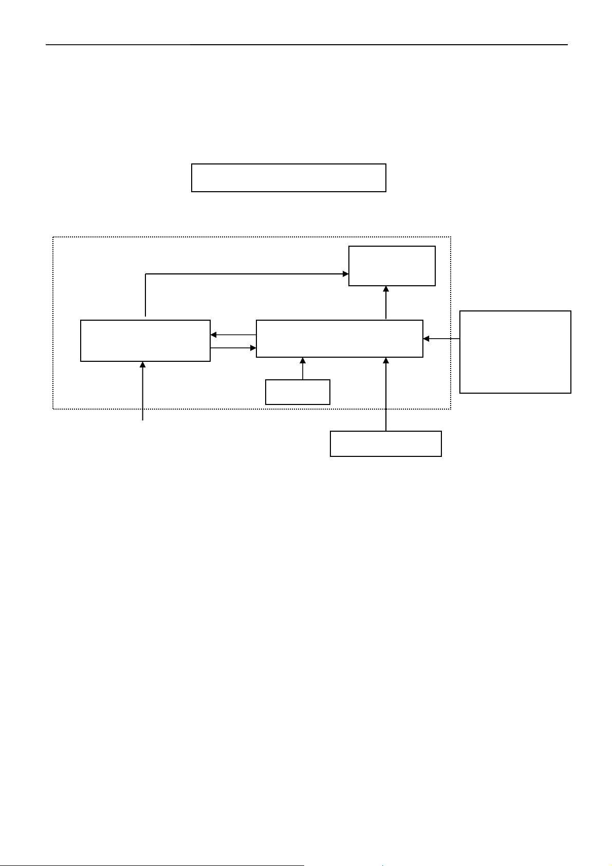
2. LCD Monitor Description
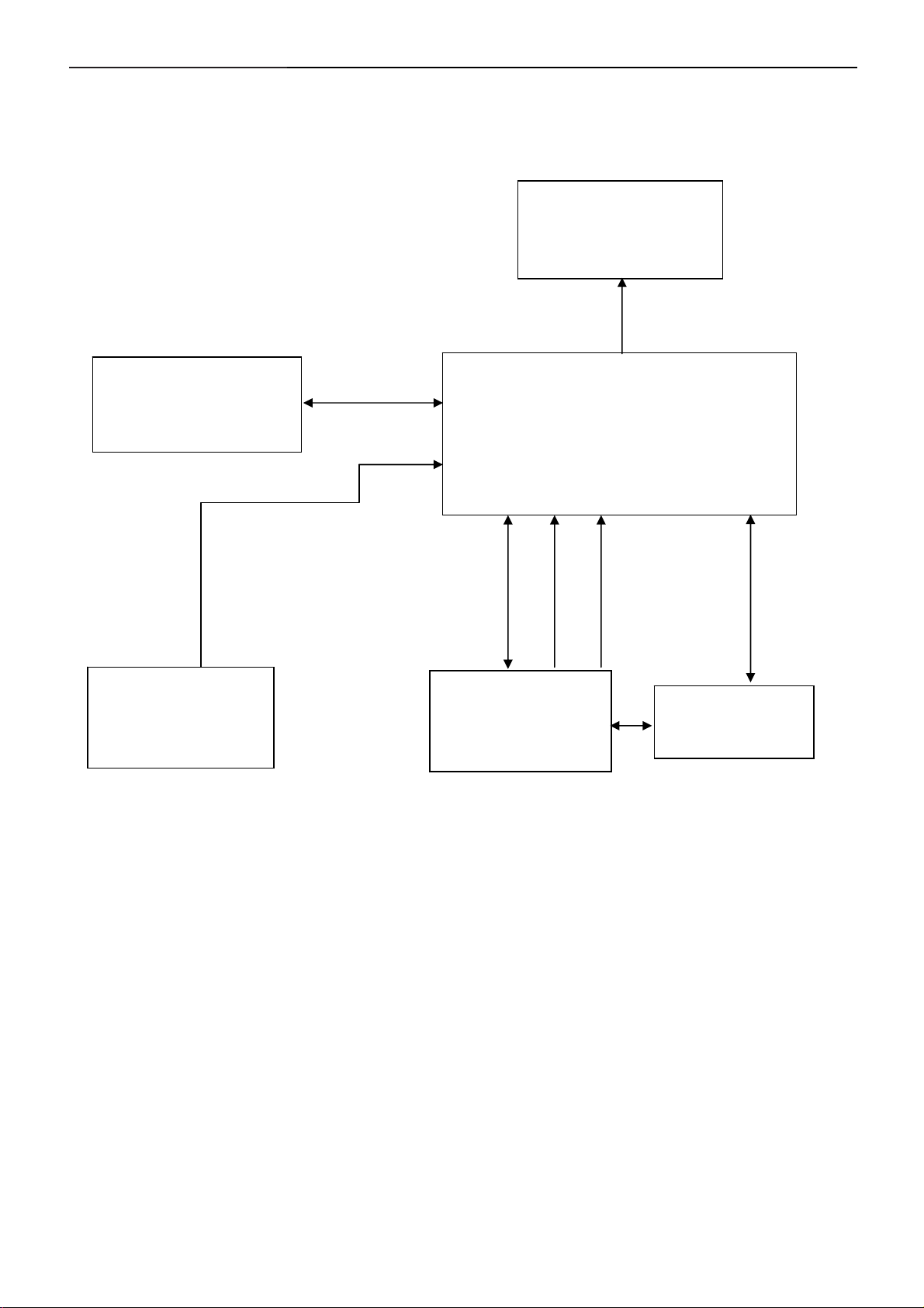
The LCD monitor will contain a main board, PWPC board, keypad board, which hou se the flat panel control logic,
brightness control logic and DDC.
The power board will provide AC to DC Inverter voltage to drive the backlight of panel and the main board chips
each voltage.
Monitor Block Diagram
CCFL Drive.
Flat Panel and
CCFL backlight
Power board
Main Board
Keyboard
RS232 Connector
For white balance
adjustment in factory
mode
AC-IN
HOST Computer
100-240V
Video signal, DDC
6
Page 7
17" LCD Color Monitor Dell E177FPc
3. Operation instructions
3.1 General Instructions
Press the power button to turn the monitor on or off. The other control buttons are located at front panel of the
monitor. By changing thes e settings, the picture can be adjusted to your personal preferences.
The power cord should be connected.
-
Connect the video cable from the monitor to the video card.
-
Press the power button to turn on the monitor, the power indicator will light up.
-
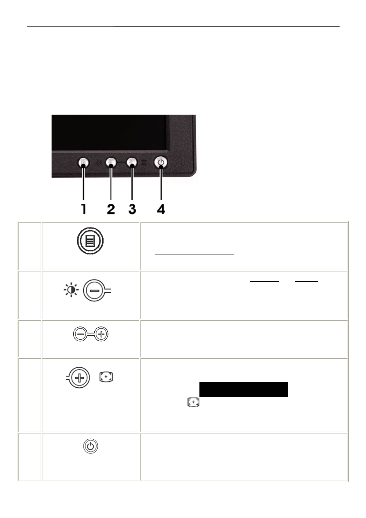
3.2 Control Buttons
1 Menu selection button
2 Brightness Contrast / Down (-) button
3 Auto-Adjust / Up (+) button
4 Power button On/Off button with indicator
A
MENU
B
Brightness/Contrast Hot Key
B C
- and + buttons
C
Auto Adjust
The 'MENU' button is used to open the on-screen display (OSD), select
function icons, exit from menus and sub-menus, and to exit the OSD.
See Accessing the Menu System.
Use this button for direct access to the 'Brightness
menu.
Use these buttons to adjust (decrease/increase ranges) items in the OSD.
Use this button to activate automatic setup and adjustment. The following
dialog will appear on screen as the monitor self-adjusts to the current input:
Auto Adjust In Progress
Auto Adjustment button allows the monitor to self-adjust to the
incoming video signal. After using 'Auto Adjustment', you can further tune
' and 'Contrast' control
your monitor by using the 'Pixel Clock' and 'Phase' controls in the OSD.
D
Power Button & Indicator
The green LED indicates the monitor is on and fully functional. An amber
LED indicates DPMS power save mode.
The Power button turns the monitor on and off.
7
Page 8
17" LCD Color Monitor Dell E177FPc
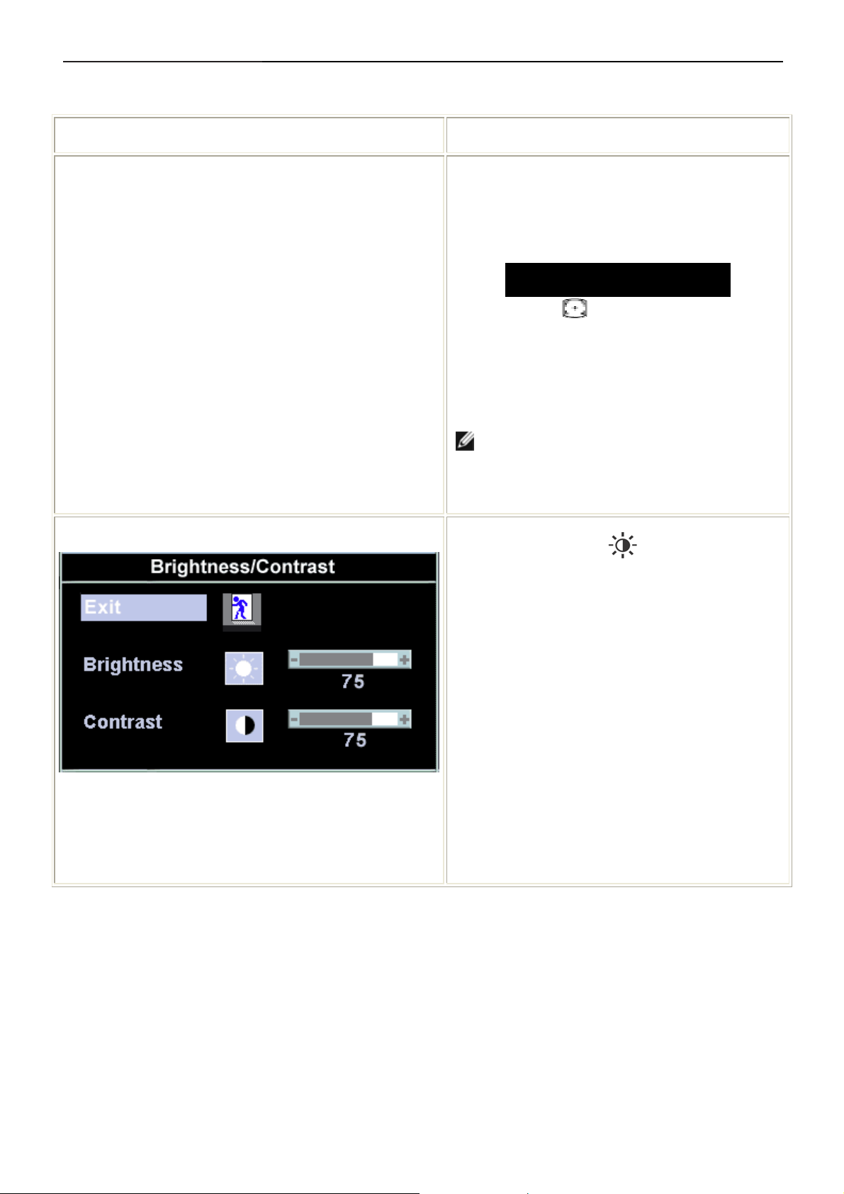
3.3 On Screen Menu/Display (OSD)
Direct-Access Functions
Function Adjustment Method
Auto adjustment
Brightness / Contrast
Use this button to activate automatic setup and
adjustment. The following dialog will appear on
screen as the monitor self-adjusts to the current
input:
Auto Adjust In Progress
Auto Adjustment button allows the monitor to
self-adjust to the incoming video signal. After using
'Auto Adjustment', you can further tune your monitor
by using the 'Pixel Clock' and 'Phase' controls in the
OSD.
NOTE: Auto Adjust will not occur if you press
the button while there are no active video input
signals, or attached cables
With the menu off, push button to display the
'Brightness' and 'Contrast' adjustment menu.
The 'Brightness' function adjusts the luminance of the
flat panel.
Adjust 'Brightness' first, then adjust 'Contrast' only if
further adjustment is necessary.
"+" increase 'brightness'
" - "decrease 'brightness'
The 'Contrast' function adjusts the degree of
difference between darkness and lightness on the
display screen.
"+" increase the 'contrast'
"-" decrease the 'contrast'
8
Page 9
17" LCD Color Monitor Dell E177FPc
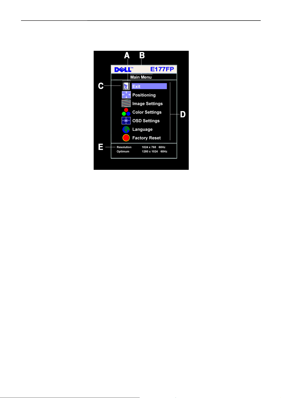
3.4 Adjusting the Picture
1. With the menu off, push the 'MENU' button to open the OSD system and display the main features menu.
A
D
2. Push the - and + buttons to move between the function icons. As you move from one icon to another, the
function name is highlighted to reflect the function or group of functions (sub-menus) represented by that
icon. See the table below for a complete list of all the functions available for the monitor.
3. Push the 'MENU' button once to activate the highlighted function; Push -/+ to select the desired parameter,
push menu to enter the slide bar. Then use the - and + buttons, according to the indicators o n the menu, to
make your changes.
4. Push the 'Menu' button once to return to the main menu to select anothe r function or push the ‘Menu’
button two or three times to exit from the OSD.
Function icons
Sub-Menu name
B
E
Main Menu
Resolution
C
Menu icon
9
Page 10
17" LCD Color Monitor Dell E177FPc
r
Icon Menu Name and
Sub-menus
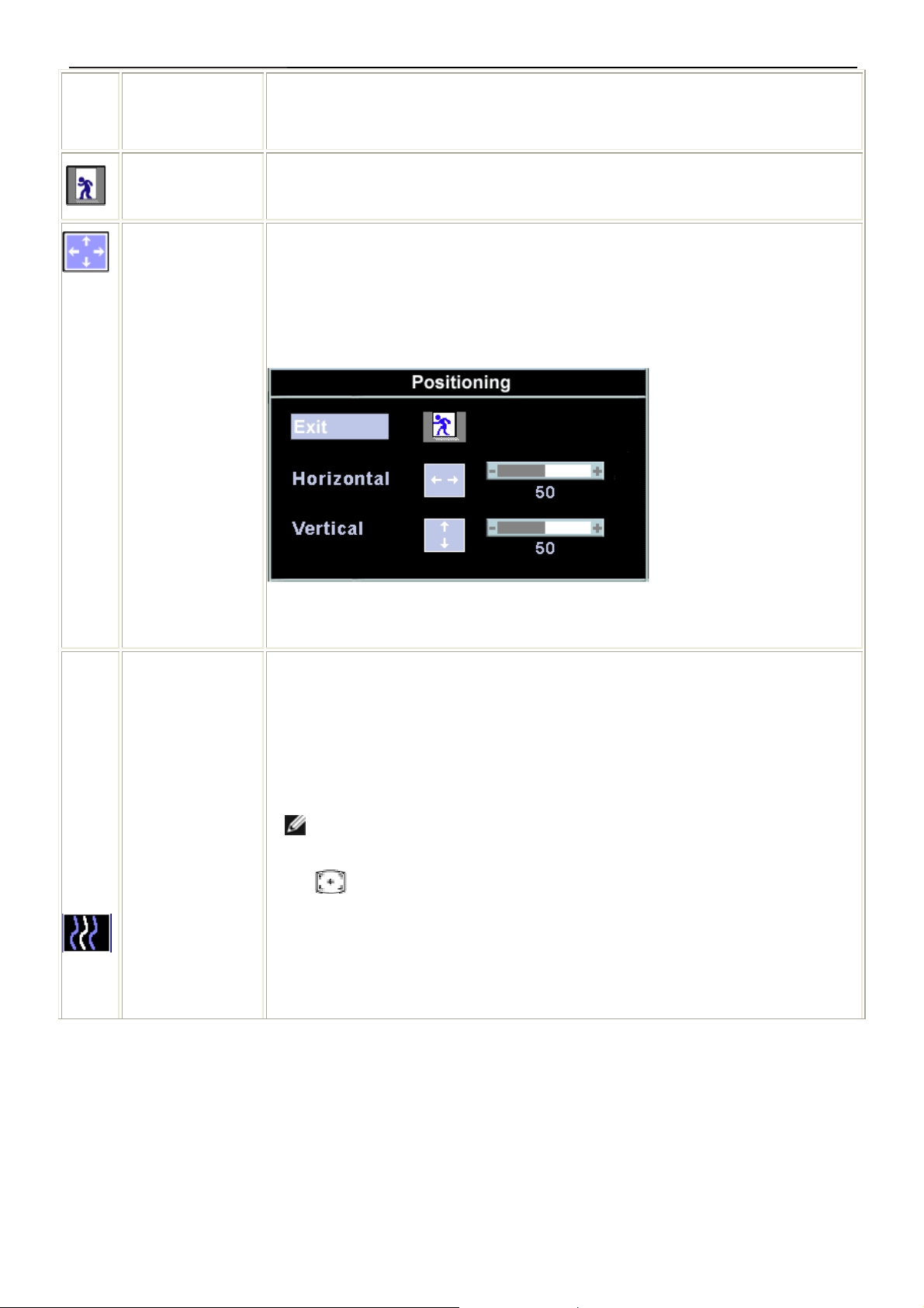
EXIT This is used to exit out of the 'Main menu'.
Positioning:
Horizontal
Vertical
Description
'Positioning' moves the viewing area around on the monitor screen.
When making changes to either the 'Horizontal' or 'Vertical' settings, no changes will
occur to the size of the viewing area; the image will simply be shifted in response to
your selection/change.
Minimum is '0' (-). Maximum is '100' (+).
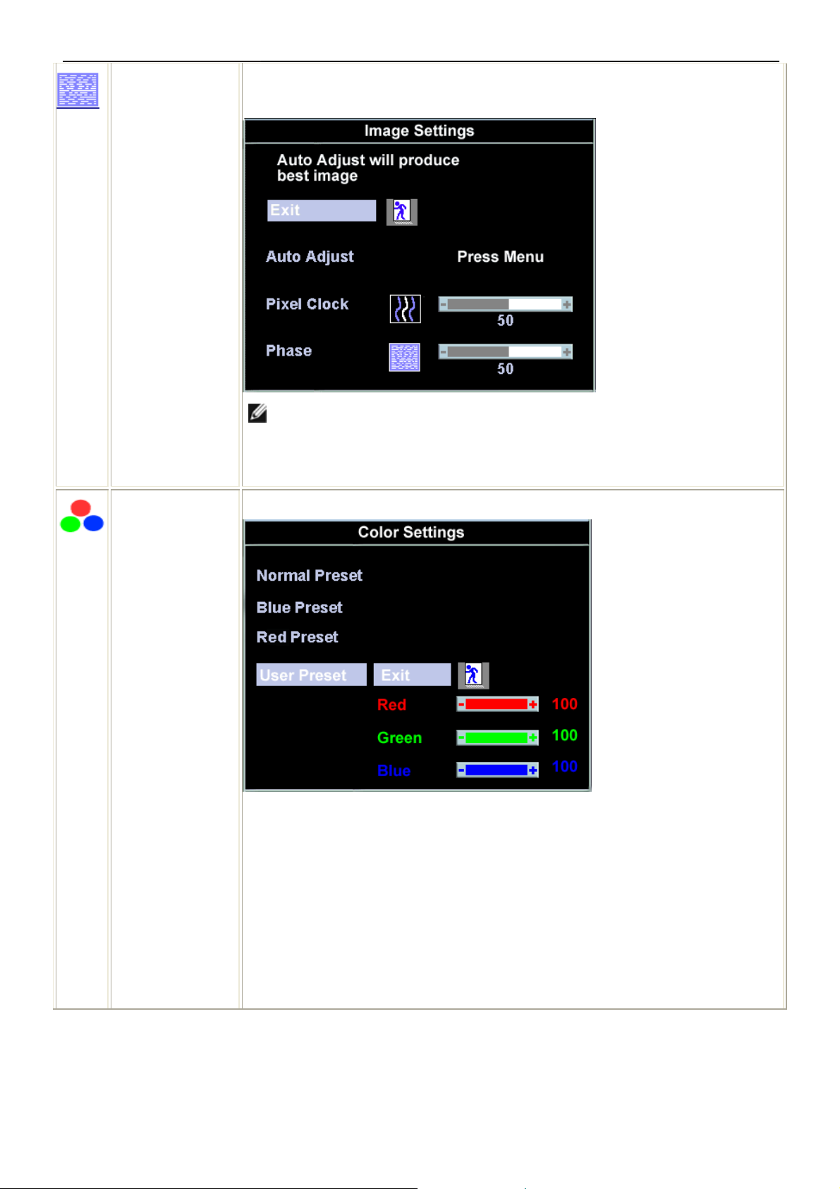
Image settings:
Auto Adjust Even though your computer system can recognize your new flat panel monitor on
startup, the 'Auto Adjustment' function will optimize the display settings for use with
your particular setup.
NOTE: In most cases, 'Auto Adjust' will produce the best image for your
configuration; this function can be directly access via Auto Adjustment
hotkey.
Pixel Clock The 'Phase' and 'Pixel Clock' adjustments allow you to more closely adjust your monito
to your preference. These settings are accessed through the main OSD menu, by
selecting 'Image Settings'.
Use the - and + buttons to adjust away interference. Minimum: 0 ~ Maximum: 100
10
Page 11
17" LCD Color Monitor Dell E177FPc
Phase If satisfactory results are not obtained using the 'Phase' adjustment, use the 'Pixel
Clock' adjustment and then use 'Phase' again.
NOTE: This function may change the wid t h of the display image. Use the
'Horizontal' function of the 'Position' menu to center the display image on the
screen.
Color Settings: 'Color Settings' adjusts the color temperature and saturation.
Normal Preset 'Normal Preset' is selected to obtain the default (factory) color settings.
Blue Preset 'Blue Preset' is selected to obtain a bluish tint. This color setting i s typically used for text
based applications (Spre adsheets, Programming, Text Editors etc.).
Red Preset 'Red Preset' is selected to obtain a redder tint. This color setting is typically used for
color intensive applications (Photograph Image Editing, Multimedia, Movies etc.).
11
Page 12
17" LCD Color Monitor Dell E177FPc
User Preset 'User Preset': Use the plus and minus buttons to increase or decrease each of the
three colors (R, G, B) independently, in single digit increments, from '0' to '100'.
NOTE: 'Color temperature' is a measure of the 'warmth' of the image colors
(red/green/blue). The two available presets ('Blue' and 'Red') favor blue and red
accordingly. Select each one to see how each range suits your eye; or utilize the
'User Preset' option to customize the color settings to your exact choice.
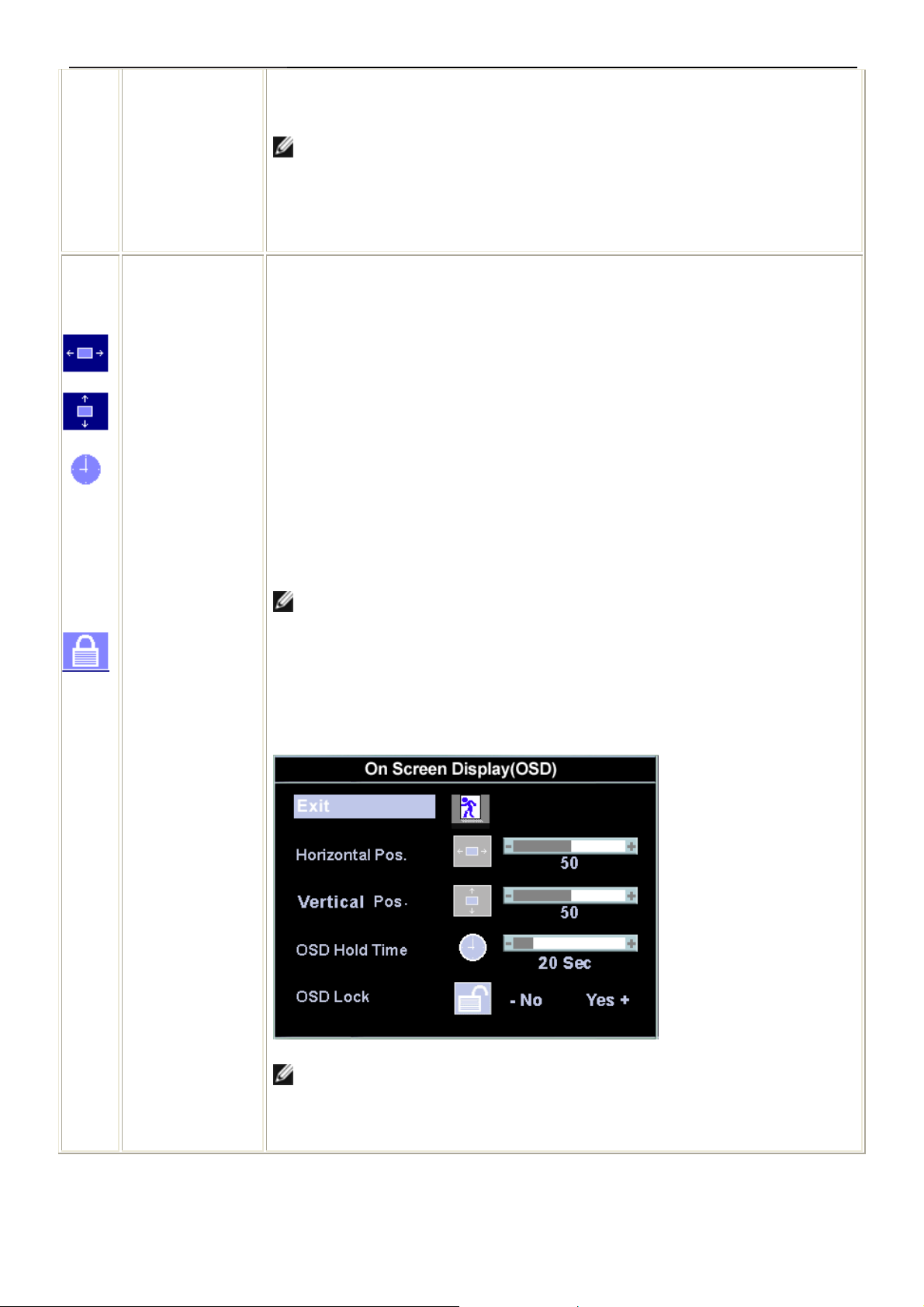
OSD Settings: Each time the OSD opens, it displays in the same location on the screen. 'OSD
Settings' (horizontal/vertical) provides control over this location.
Horizontal Position - and + buttons move OS D to the left and right.
Vertical Positi on - and + buttons move OSD down and up.
OSD Hold Time: The OSD stays active for as long as it is in use.
'OSD Hold Time': Sets the length of time the OSD will remain active after the last time
you pressed a button.
Use the - and + buttons to adjust the slider in 5 second increments, from 5 to 60
seconds.
NOTE: Default 'OSD hold time' is 20 seconds.
OSD Lock 'OSD Lock': Controls user access to adjustments. When 'Yes' (+) is selected, no user
adjustments are allowed. All buttons are locked except the menu button.
All buttons can be locked or unlocked press the 'Menu' button for over 15 seconds. to
unlock the OSD 'Menu'.
NOTE: When the OSD is locked, pressing the 'Menu' button will take the user
directly to the 'OSD settings' menu, with 'OSD Lock' preselected on entry . Select
'No'(-) to unlock and allow user access to all applicable settings.
12
Page 13
17" LCD Color Monitor Dell E177FPc
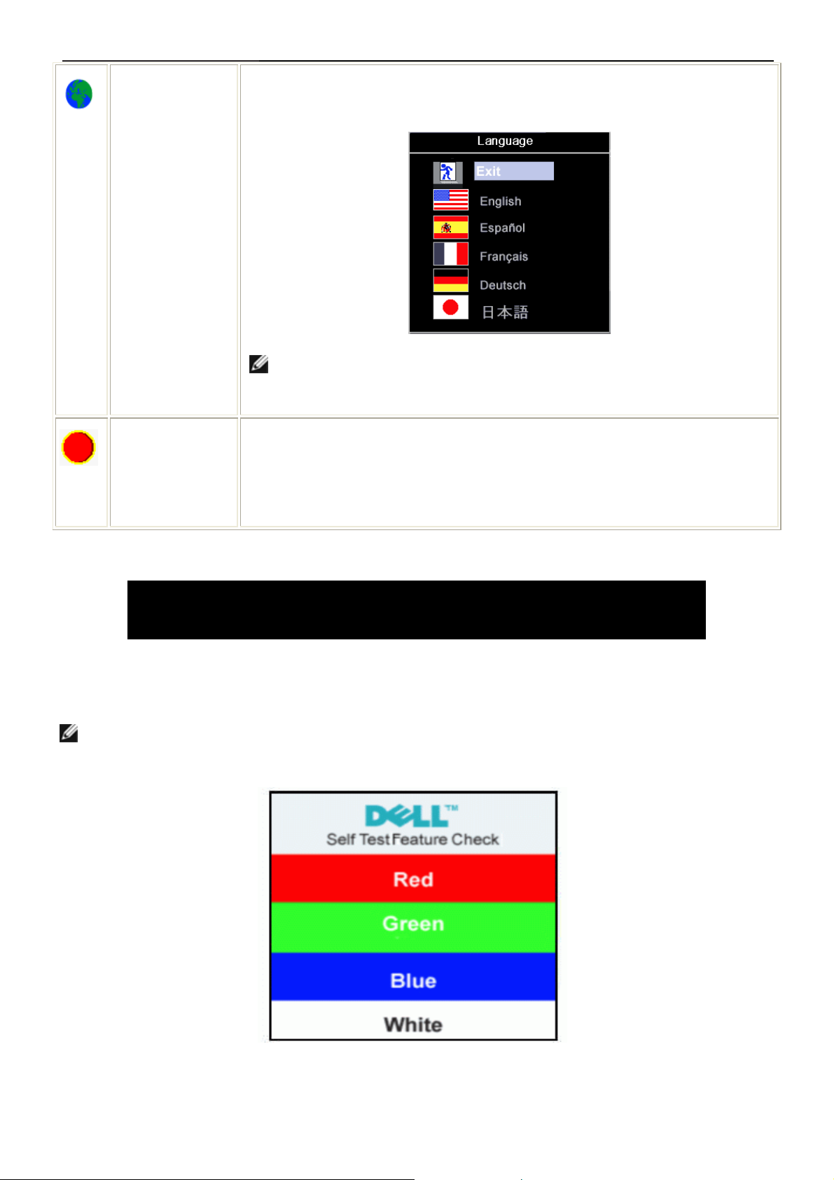
Language: Language sets the OSD to display in one of five languages (English, Español,
Français, Deutsch, Japanese ).
NOTE: The language chosen affects only the language of the OSD. It has no
effect on any software runn ing on the computer.
Factory Reset: 'Factory Reset' returns the settings to the factory preset values for the selected group
of functions. 'Exit' is used to exit out of 'Factory Reset' menu.
For 'All settings', all user adjustable settings are reset at one time except 'Language
settings'.
OSD Warning Messages
A warning message may appear on the screen indicating that the monitor is out of sync.
Cannot Display This Video Mode
Optimum resolution 1280 x1024 60Hz
This means that the monitor cannot synchronize with the signal that it is receiving from the computer. Either the
signal is too high or too low for the monitor to use. See Specifications for the Horizontal and Vertical frequency
ranges addressable by this monitor. Recommended mode is 1280 X 1024 @ 60Hz.
NOTE: The floating 'Dell - self-test Feature Check' dialog will appear on-screen i f the monitor cannot sense a
video signal.
Occasionally, no warning message appears, but the screen is blank. This could also indicate that the monitor is not
synchronizing with the computer. See Troublesh ooting for more information.
13
Page 14
17" LCD Color Monitor Dell E177FPc
4. Input/Output Specification
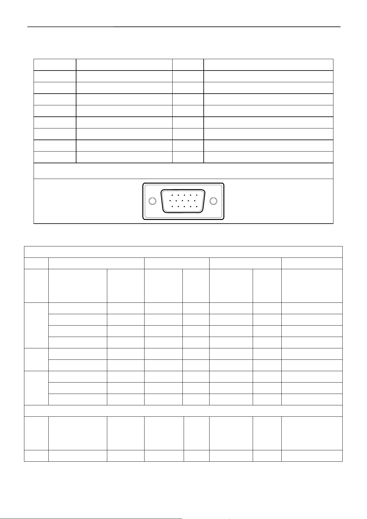
4.1 Input Signal Connector
Pin No. Description Pin No. Description
1. Red Video 9. Computer 5V/3.3V
2. Green Video 10. GND-sync
3. Blue Video 11. GND
4. GND 12. DDC-Serial Data
5. Self-test 13. H-Sync
6. R-Ground 14. V-Sync
7. G-Ground 15. DDC-Serial Clock
8. B-Ground
VGA Connector layout
15
6
11 15
10
4.2 Factory Preset Display Modes
VESA MODES
Horizontal Vertical
Mode Resolution Total
640x480@60Hz 800 x 525 31.469 N 59.940 N 25.175
VGA
XGA
SXGA
640x480@75Hz 840 x 500 37.500 N 75.00 N 31.500
800x600@60Hz 1056 x 628 37.879 P 60.317 P 40.000
800x600@75Hz 1056x625 46.875 P 75.000 P 49.500
1024x768@60Hz 1344x806 48.363 N 60.004 N 65.000
1024x768@75Hz 1312x800 60.023 P 75.029 P 78.750
1152x864@75Hz 1600x900 67.500 P 75.000 P 108.00
1280x1024@60Hz 1688x1066 64.000 P 60.000 P 108.00
Nominal
Frequency
+/- 0.5kHz
Sync
Polarit
y
Nominal
Freq.+/- 1Hz
Sync
Polarity
Nominal
Pixel Clock (MHz)
1280x1024@75Hz 1688x1066 79.976 P 75.025 P 135.00
IBM MODES
Nominal
Mode Resolution Total
DOS 720x400@70Hz 900 x 449 31.469 N 70.087 P 28.322
Frequency
+/- 0.5kHz
14
Sync
Polarit
y
Nominal
Freq. +/- 1
Hz
Sync
Polarity
Nominal Pixel
Clock (MHz)
Page 15
17" LCD Color Monitor Dell E177FPc
4.3 Power Supply Requirements
A/C Line voltage range 100 V ~ 240 V± 10 %
A/C Line frequency range 50 ± 3Hz, 60 ± 3Hz
Input Voltage transients 280 volts AC for 10 sec @40℃
Current 0.6A max. at 100V, 0.35A max. at 240 V
< 60A peak at 240 VAC and cold starting
Peak surge current
< 30A peak a t 120VAC and cold starting
Leakage current < 3.5mA
No advance effects (no loss of information or defect)
Power line surge
with a maximum of 1 half-wave missing per second
15
Page 16
17" LCD Color Monitor Dell E177FPc
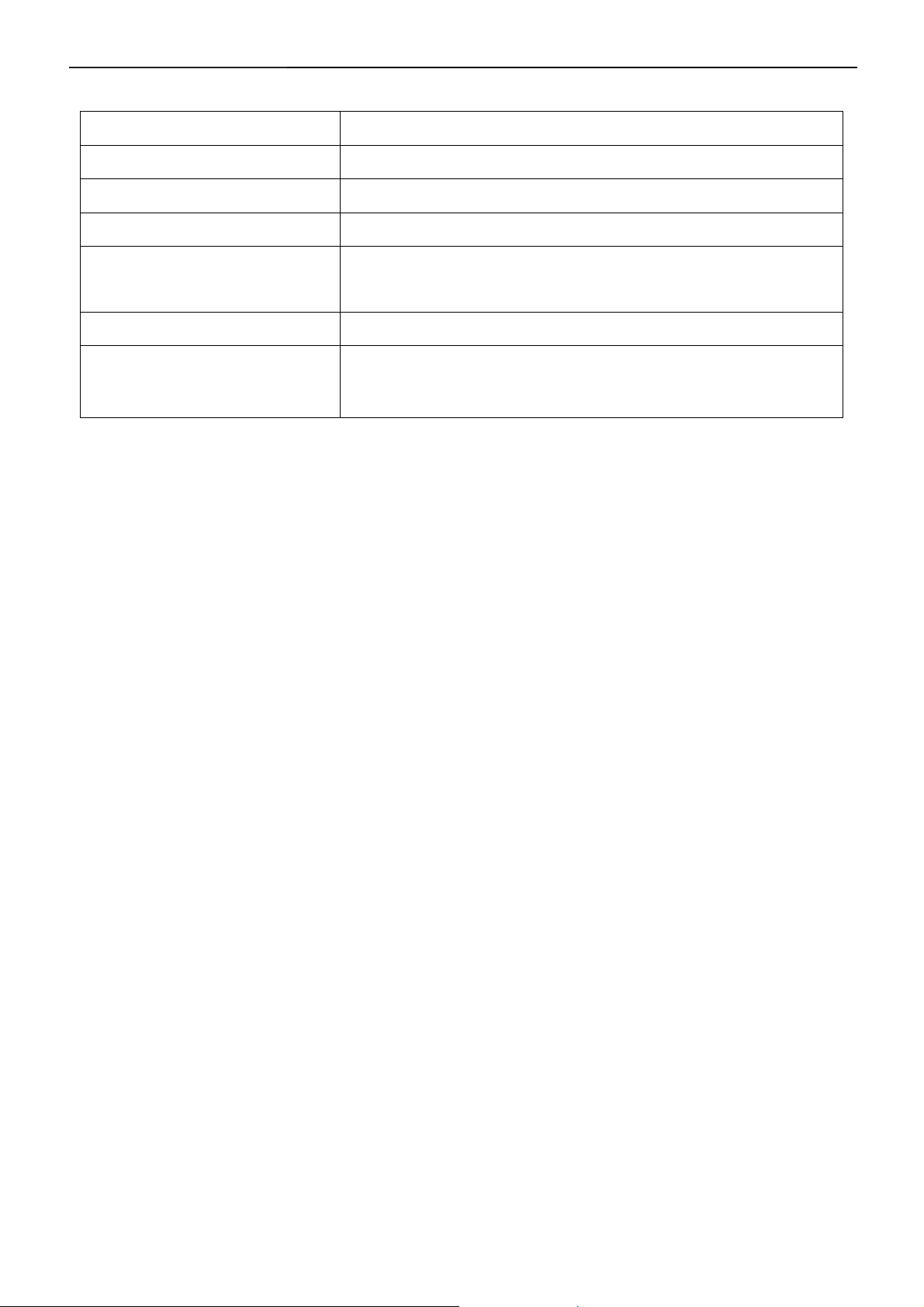
4.4 Panel Specification
4.4.1 Display Characteristics
For LM170E01-TLB3 panel
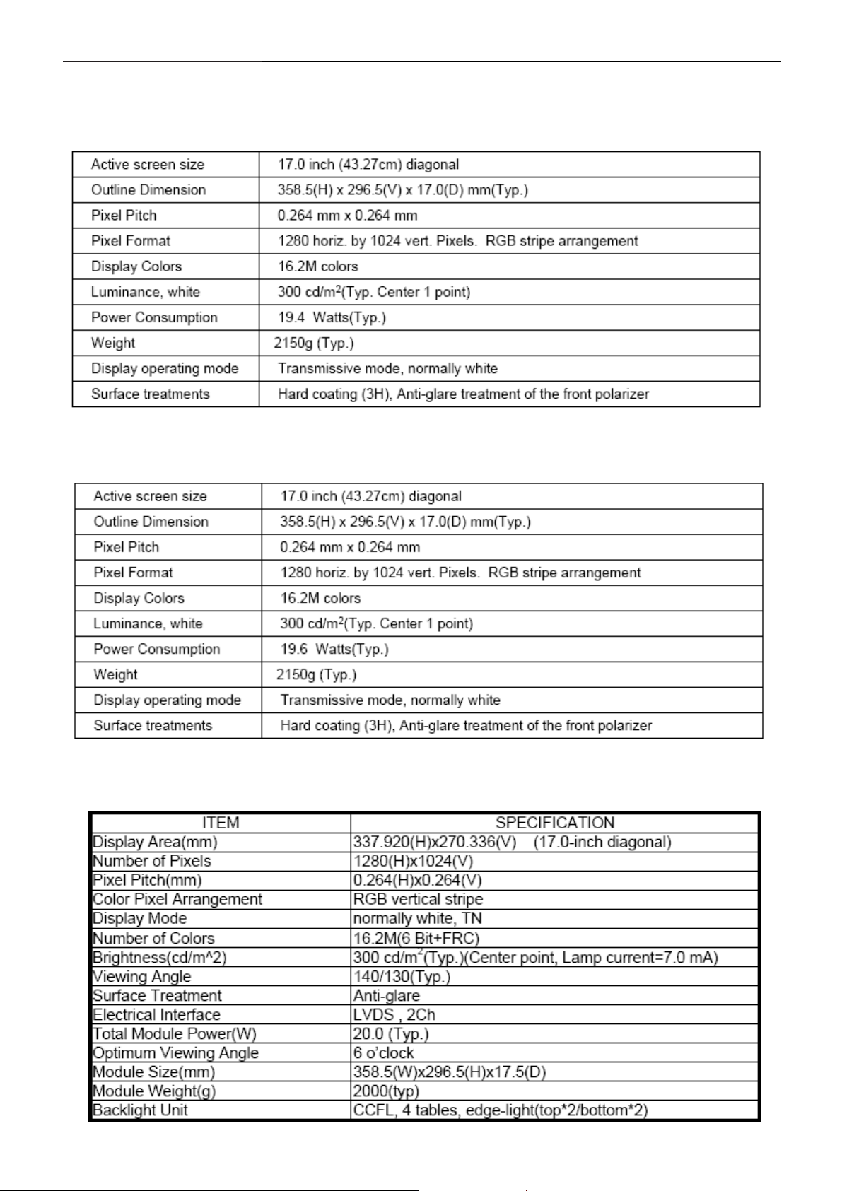
For LM170E01-TLB4 panel
For CLAA170EA07Q Rev.373/3A3 panel
16
Page 17
17" LCD Color Monitor Dell E177FPc
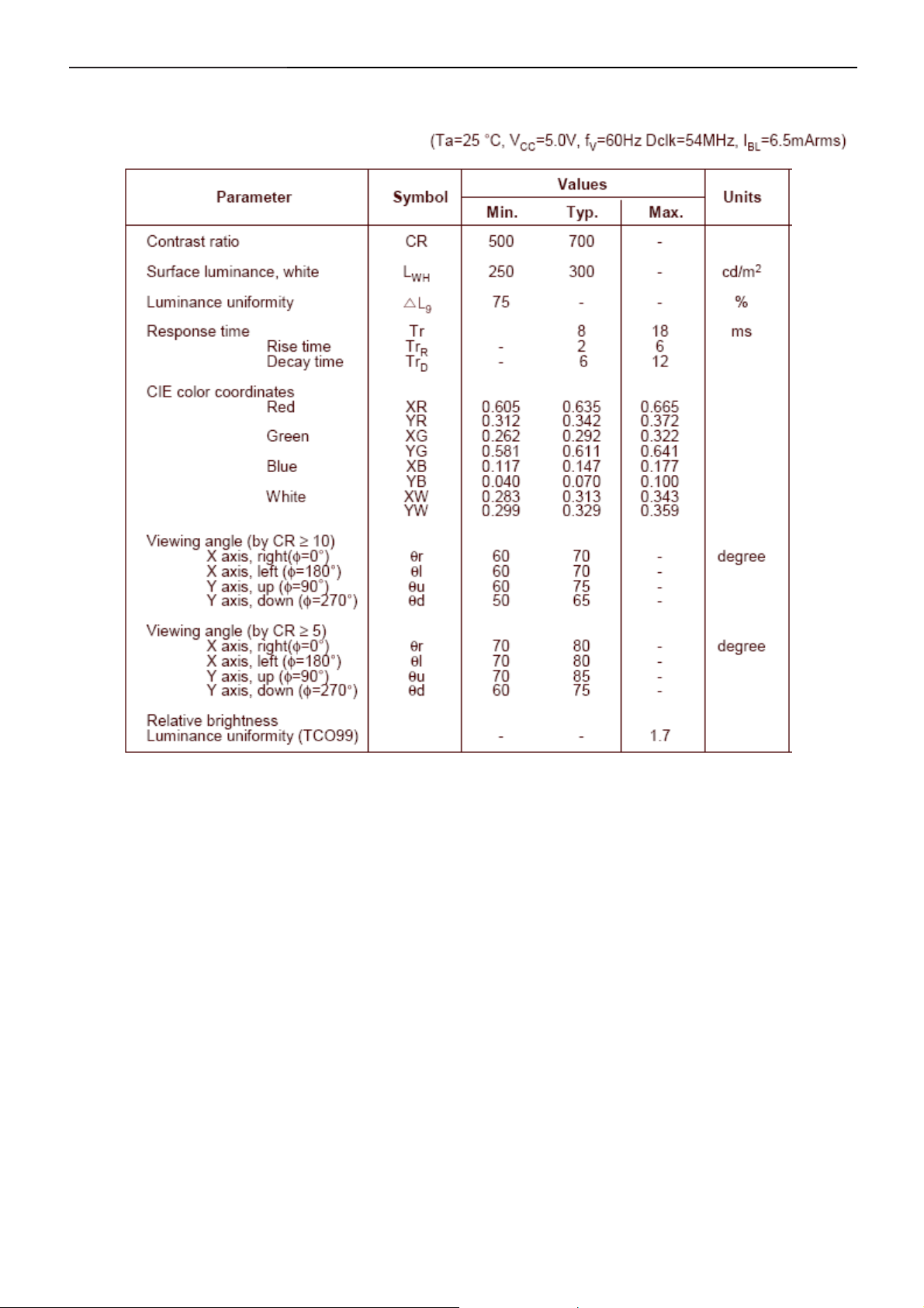
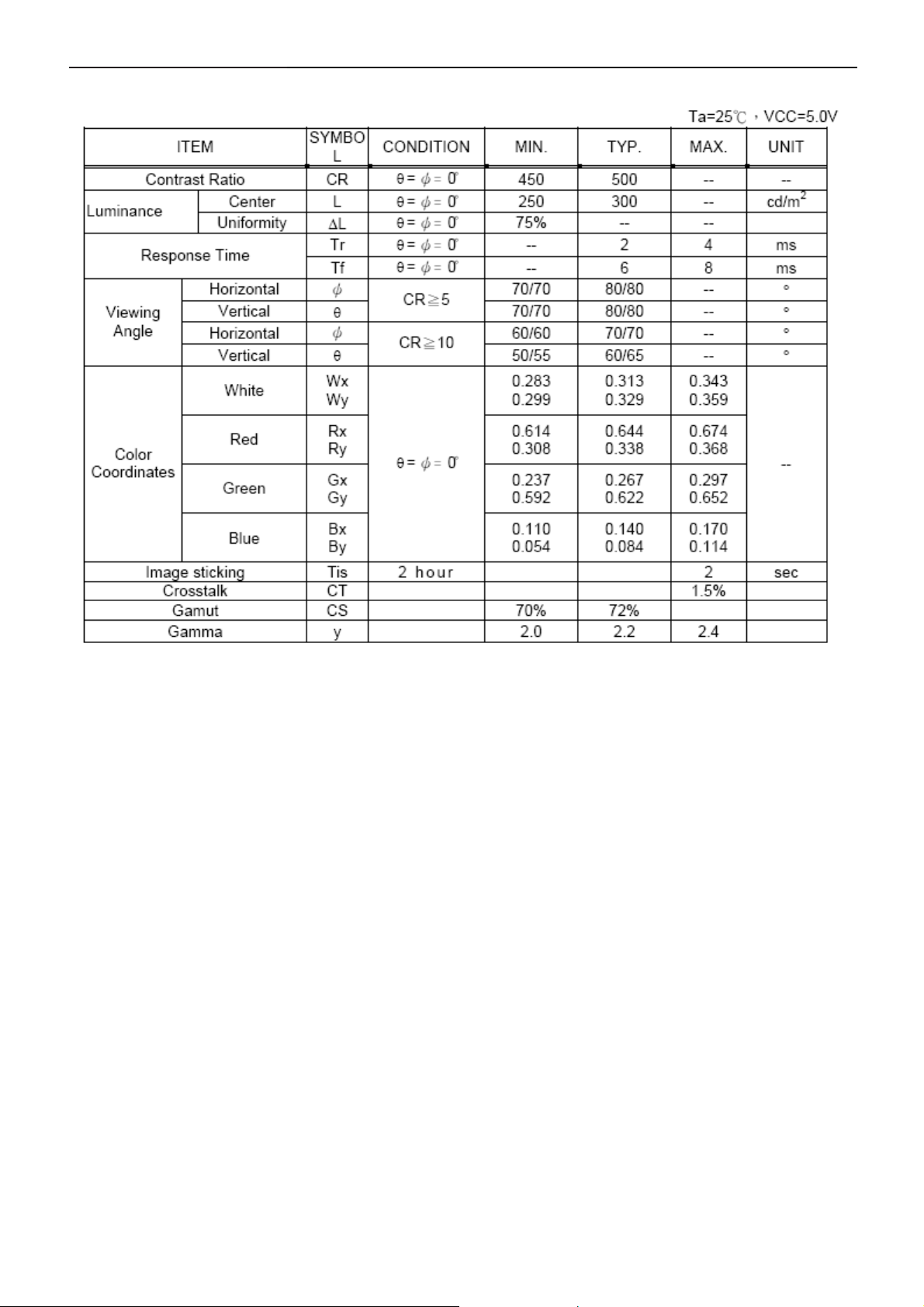
Optical Characteristics
For LM170E01- TLB3/TLB4 panel
17
Page 18
17" LCD Color Monitor Dell E177FPc
For CLAA170EA07Q Rev.373/3A3 panel
18
Page 19
17" LCD Color Monitor Dell E177FPc
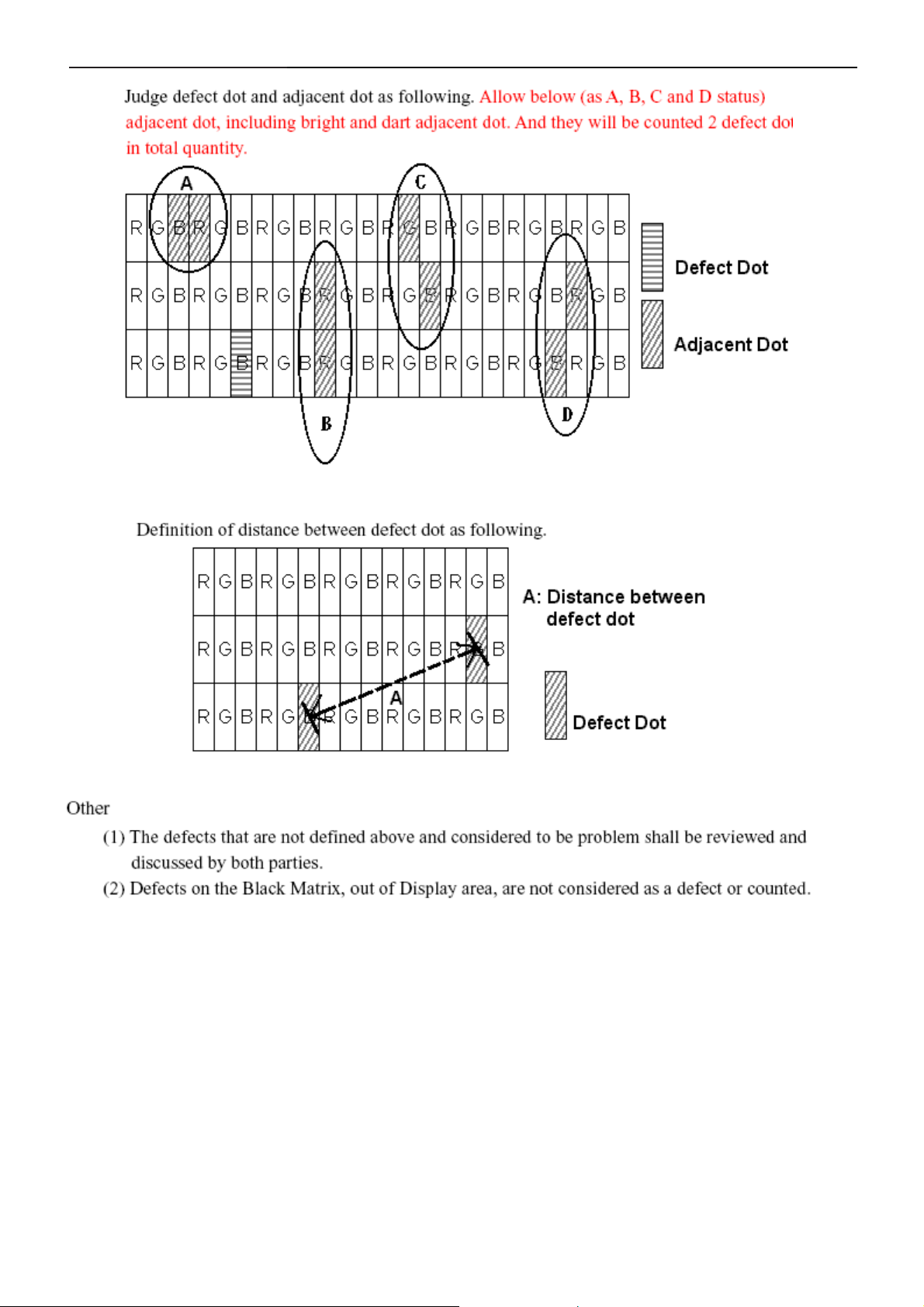
4.5 Definition Of Pixel Defects
For LM170E01- TLB3/TLB4 panel
Dot Defect
Bright Dot
Dots (sub-pixels), which appeared brightly in the screen when the LCM displayed with dark pattern.
- R, G or B 1 dot --------------------------------- 0 Max
- Adjacent 2 dots -------------------------------- 0 Max
- Total amount of Bright dots -------------------- 0 Max
- Minimum distance of Bright dots --------------- NA
Dark Dot
Dots (sub-pixels) which appeared darkly in the screen when the LCM displayed with bright pattern.
- 1 dot -------------------------------------------- 4 Max
- Adjacent 2 dots -------------------------------- 2 Max
- Total amount of Dark dot ---------------------- 4 Max
- Minimum distance of Dark dots --------------- 15mm
Total amount of Dot Defects -------------------- 5 Max (Combination)
Note) a. Every dot herein means Sub-Pixel (Each Red, Green, or Blue Color)
b. Bright dot
- Red or Blue dots smaller than half size of sub-pixel are not counted as a defect dots.
- Green dots smaller than 1 / 3 size of sub-pixel are not counted as a defect dots.
c. Dark dots smaller than half size of sub-pixel are not counted as a defect dots.
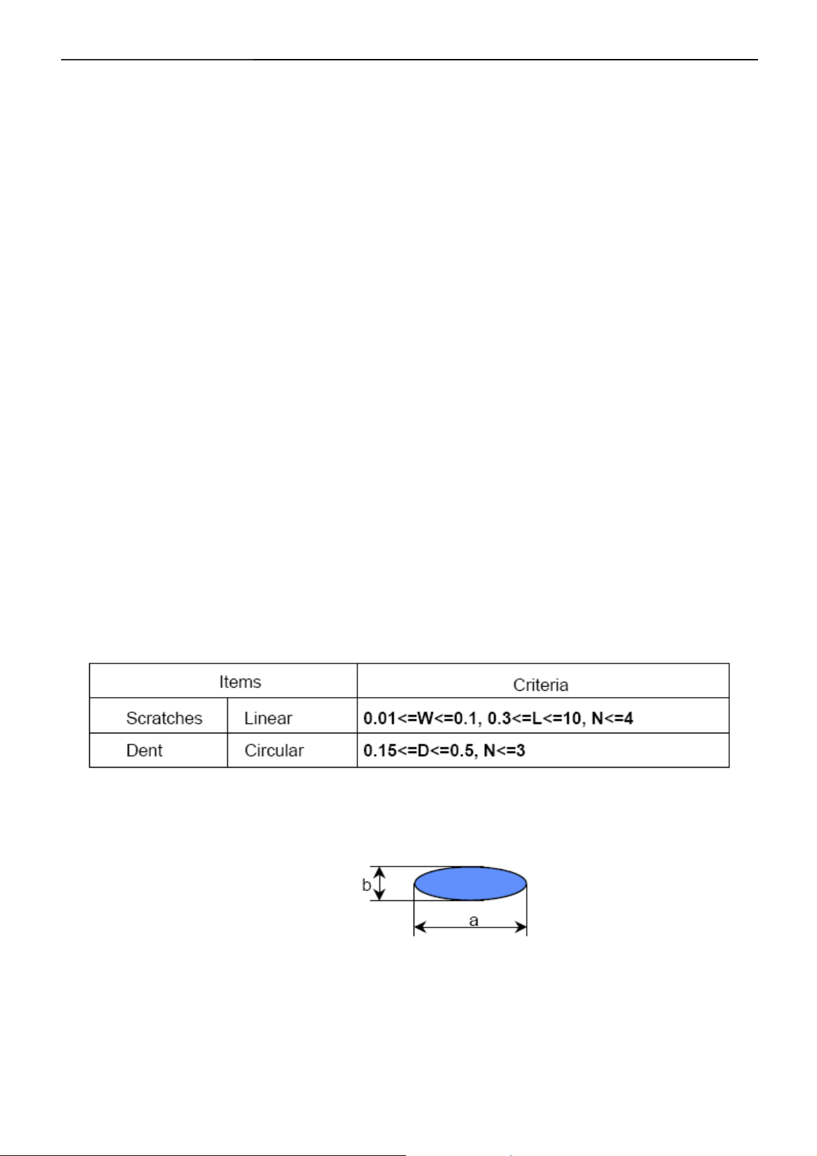
Polarizer Defects
Where, W: Width
L: Length
D: Average diameter =(a+b)/2
a. Extraneous substances, which can be wiped out, like Finger Print, Particles, are not considered as a defect.
b. Defects which are on the Black Matrix (outside of Active Area) are not considered as a defect.
19
Page 20
17" LCD Color Monitor Dell E177FPc
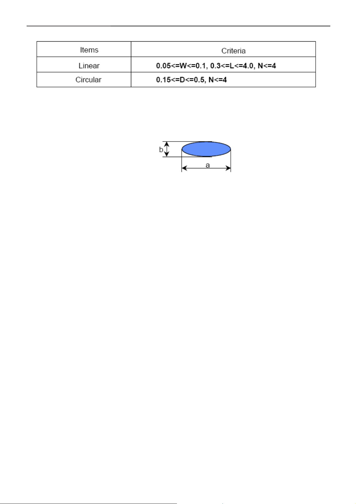
Foreign Material
Where, W: Width
L: Length
D: Average diameter =(a+b)/2
Line Defect
All kinds of line defects such as vertical, horizontal or cross are not allowed.
Bezel Appearance
Scratches, minor bents, stain, particles on the Bezel frame are not considered as a defect.
others
Issues, which are not defined in these criteria, shall be discussed with both parties, Customer and Supplier, for
better solution.
20
Page 21
17" LCD Color Monitor Dell E177FPc
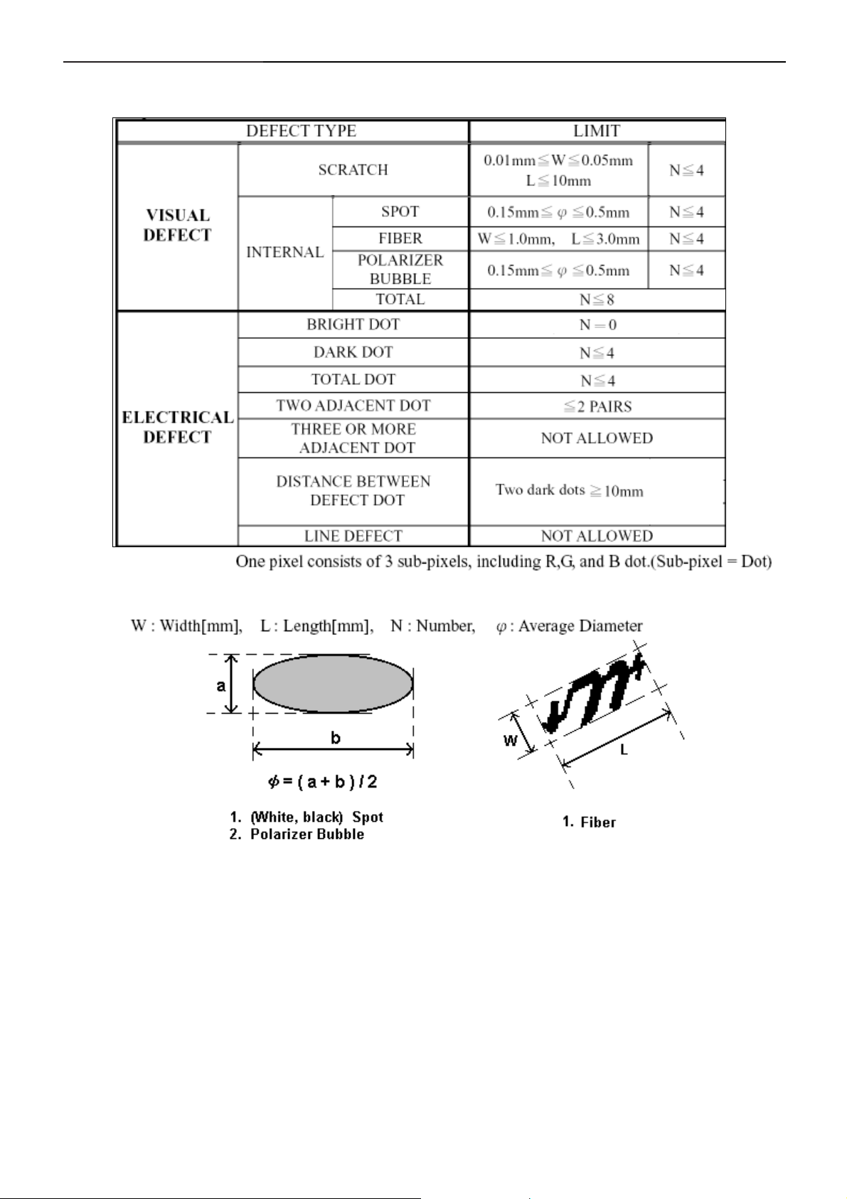
For CLAA170EA07Q Rev.373/3A3 panel
21
Page 22
17" LCD Color Monitor Dell E177FPc
22
Page 23
17" LCD Color Monitor Dell E177FPc
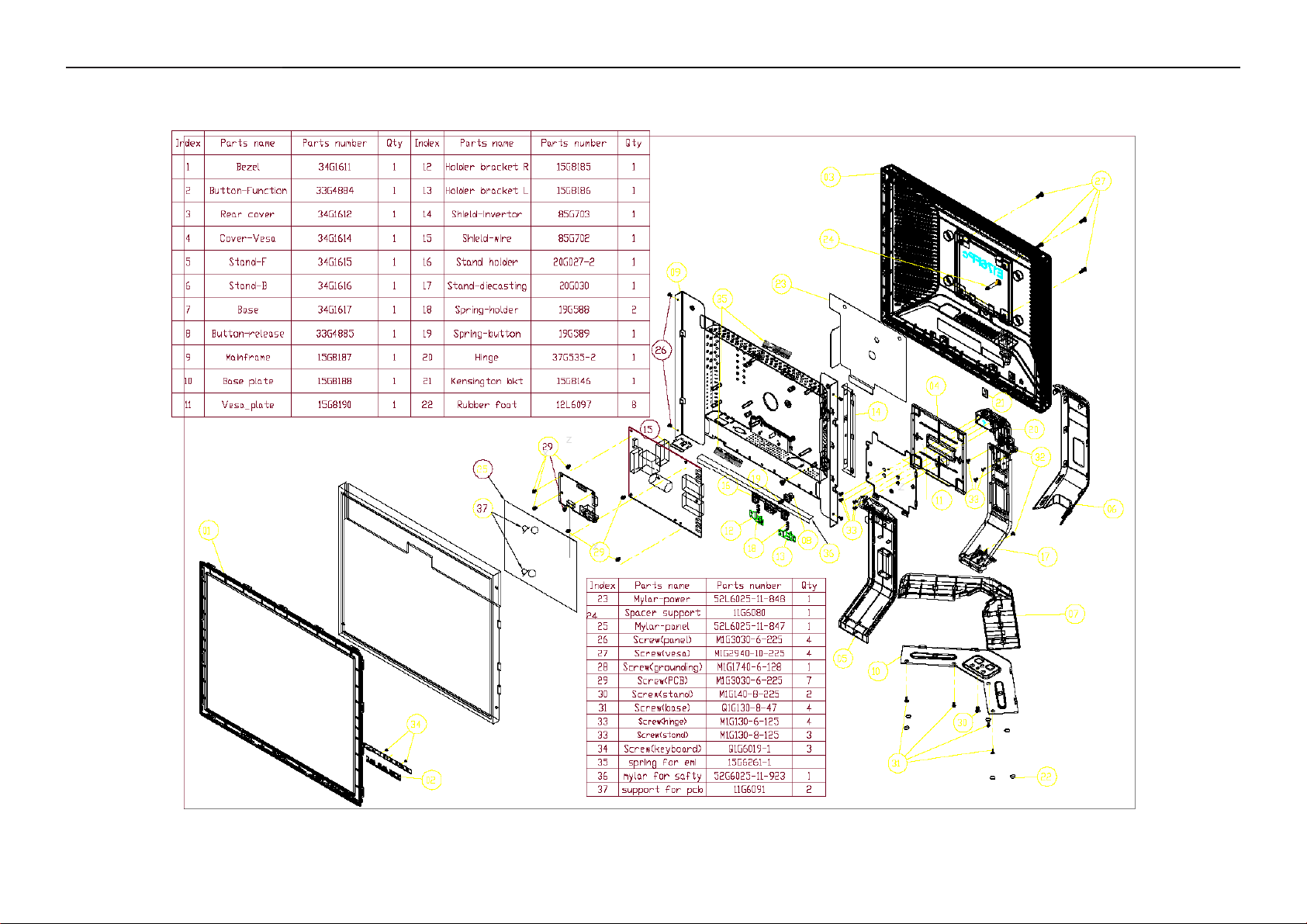
5. Block Diagram
5.1 Monitor Exploded View
23
Page 24
17" LCD Color Monitor Dell E177FPc
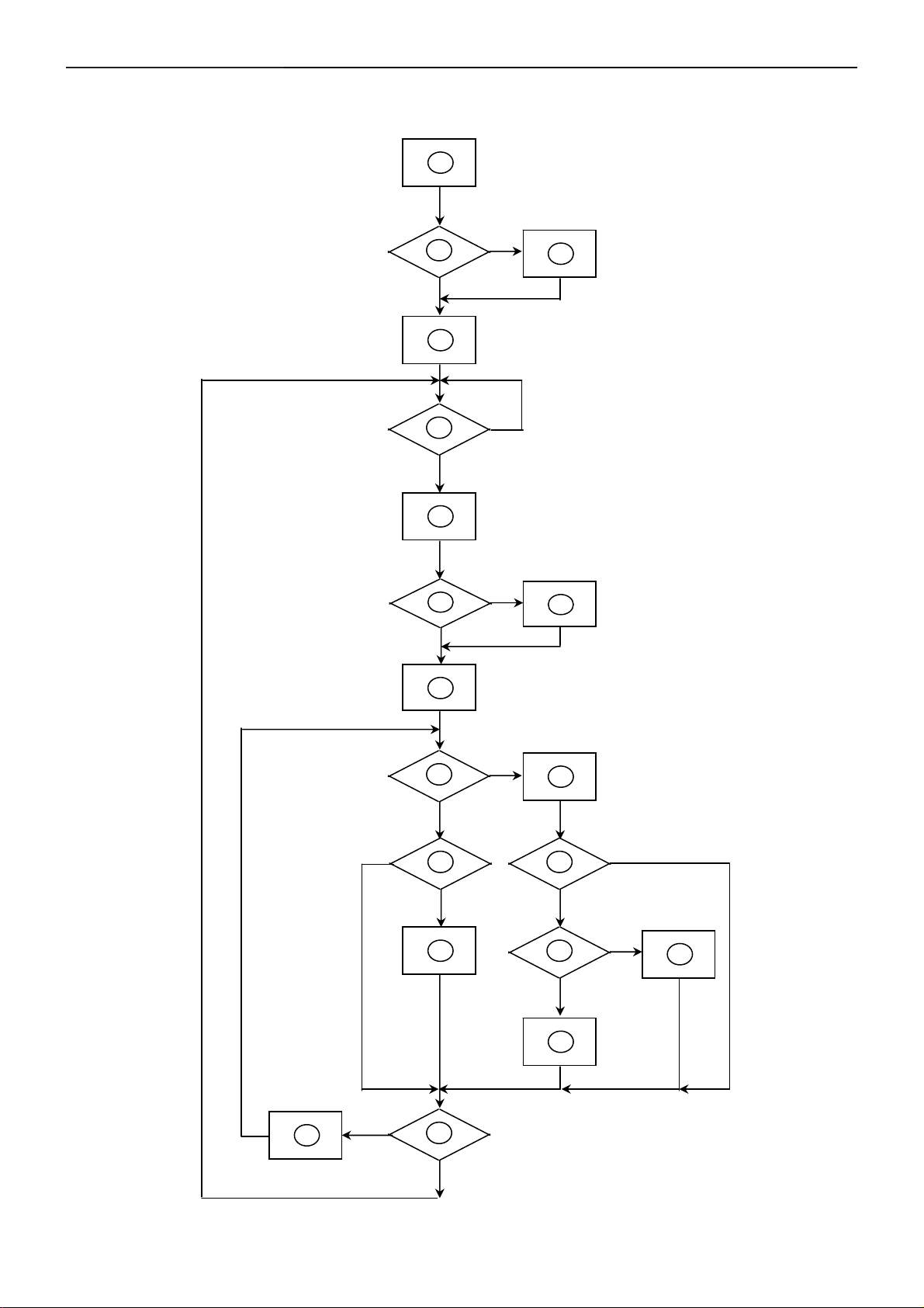
5.2 Software Flow Chart
1
2
4
Y
3
N
5
Y
6
7
9
10
Y
N
12
N
N
Y
N
11
13
8
N
Y
14
18
N
19
Y
24
15
17
Y
N
16
Y
Page 25

17" LCD Color Monitor Dell E177FPc
1) MCU Initializes.
2) Is the EEprom blank?
3) Program the EEprom by default values.
4) Get the PWM value of brightness from EEprom.
5) Is the power key pressed?
6) Clear all global flags.
7) Are the AUT O and SELECT keys pressed?
8) Enter factory mode.
9) Save the power key status into EEprom.
Turn on the LED and set it to green color. Scalar
initializes.
10) In standby mode?
11) Update the lifetime of back light.
12) Check the analog port, are there any signals coming?
13) Does the scalar send out an interrupt request?
14) Wake up the scalar.
15) Are there any signals coming from analog port?
16) Display "No connection Check Signal Cable" message. And go into standby mode after the message
disappears.
17) Program the scalar to be able to show the coming mode.
18) Process the OSD display.
19) Read the keyboard. Is the power key pressed?
25
Page 26
17" LCD Color Monitor Dell E177FPc
5.3 Electrical Block Diagram
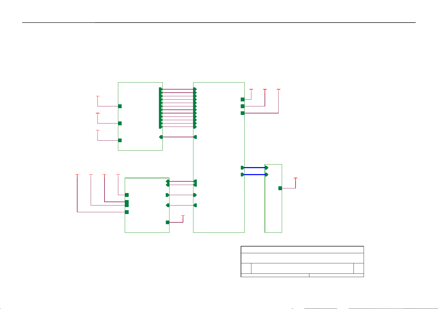
5.3.1 Main Board
Flash Memory
SST25VF010A-33- 4C-SAE
(U402)
RXD
TXD
LCD Interface
(CN101)
Scalar TSUM16AL-LF
(Include MCU, ADC, OSD)
(U401)
R
G
B
H
DB15_SDA,
V
DB15_SCL
OSD Control Interface
(CN403)
D-Sub
EEPROM M24C02
Connector
(U404)
(CN405)
26
Page 27
17" LCD Color Monitor Dell E177FPc
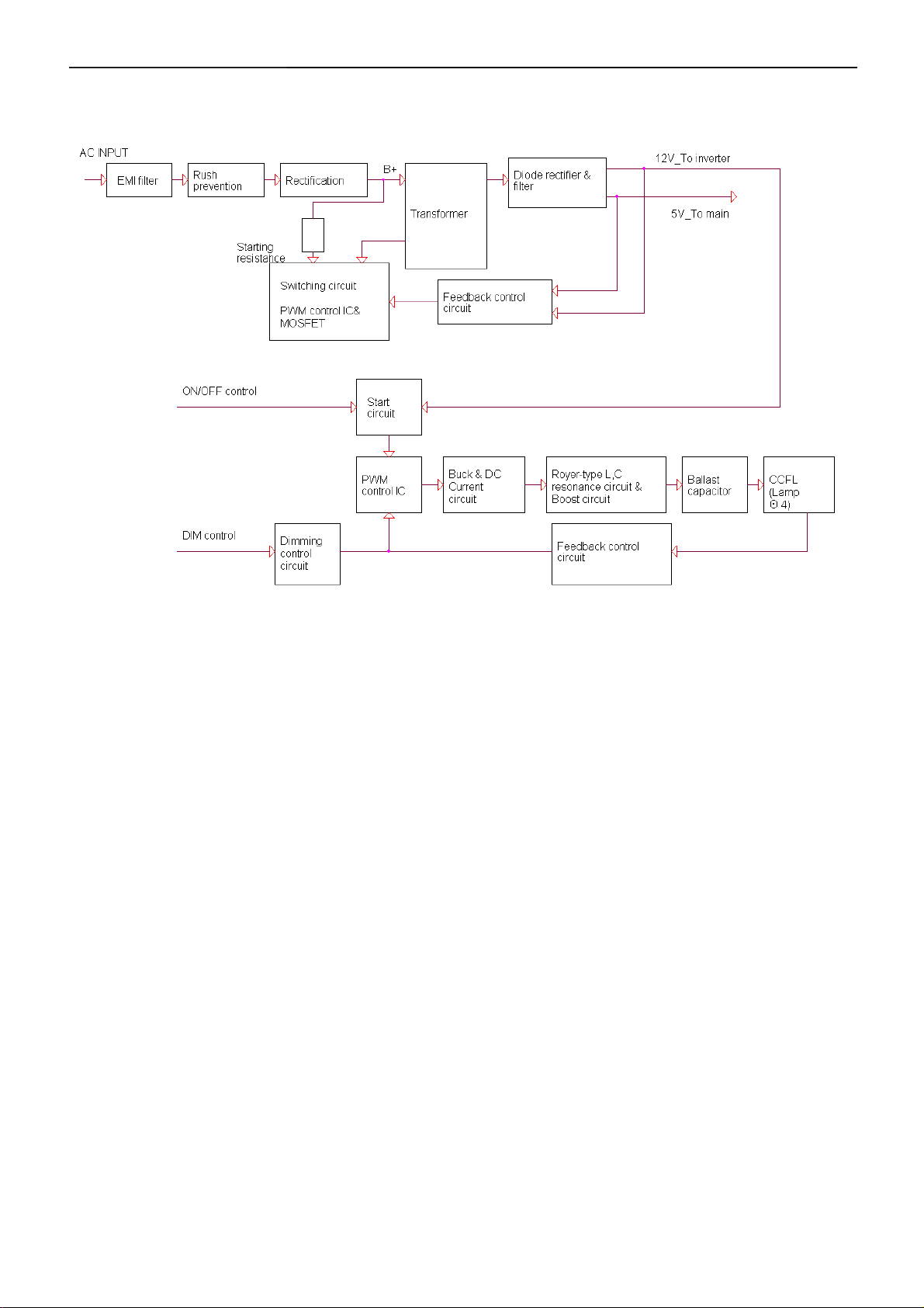
5.3.2 Inverter/Power Board
27
Page 28
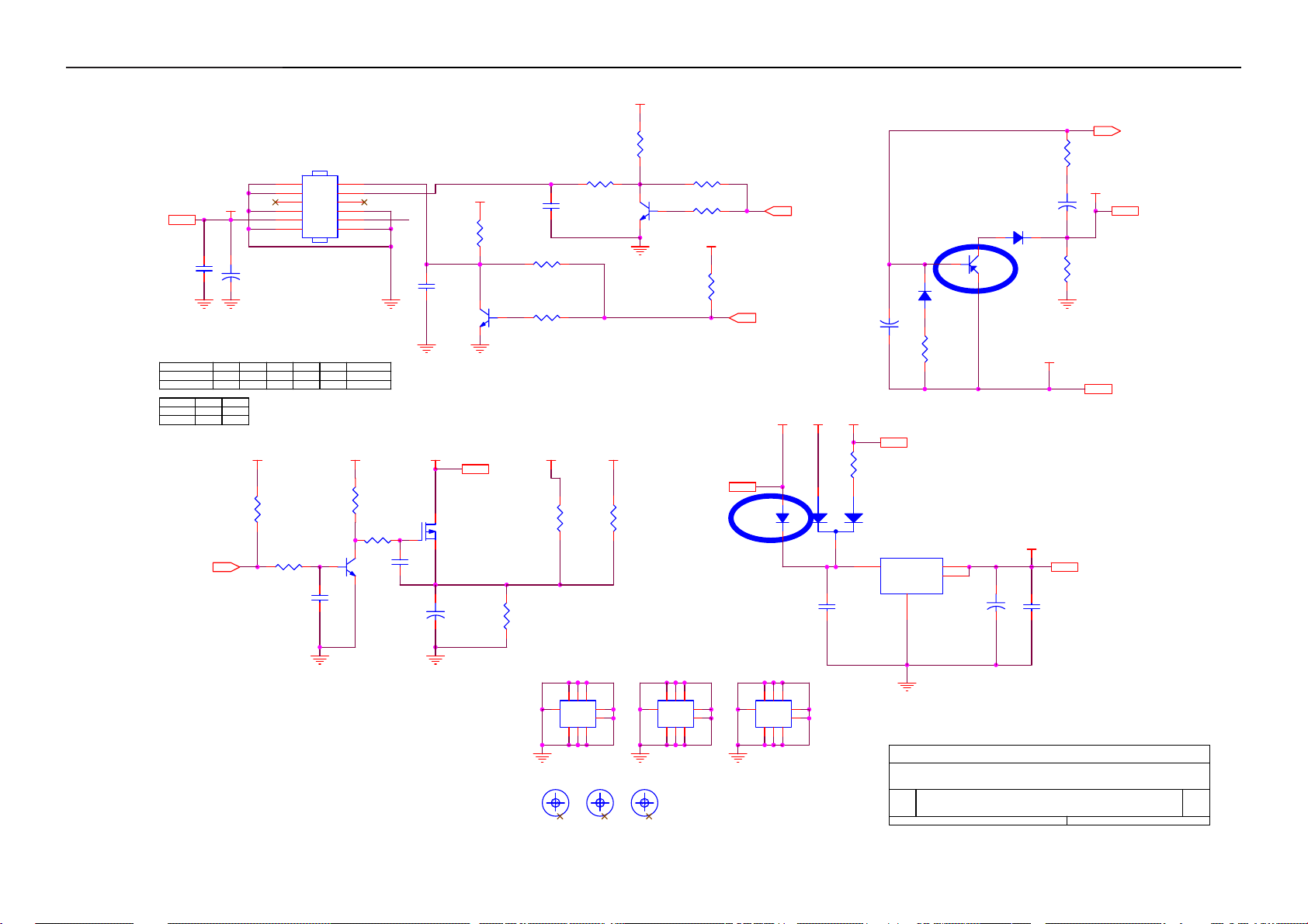
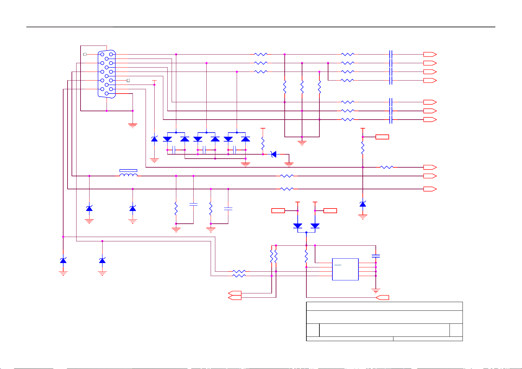
17" LCD Color Monitor Dell E177FPc
6. Schematic Diagram
6.1 Main Board
TSUM16AL SCHEMATIC
XGA/SXGA
B3
+5V
PC5V
VCC3.3
+5V
PC5V
VCC3.3
RIN
GNDR
GIN
GNDG
SOG
BIN
GNDB
HSYNC
VSYNC
DDCA_SDA
DDCA_SCL
DET_VGA
DDC_WP
B4
RIN
GNDR
GIN
GNDG
SOG
BIN
GNDB
HSYNC
VSYNC
DDCA_SDA
DDCA_SCL
DET_VGA
DDC_WP
LVDS OUTPUT
VCC1.8
VCC1.8
Vcc3.3
+5V
VCC3.3
+5V
3.INPUT
B5
A[0..9]
VCC1.8
+5VVCC3.3
PC5V
B2
PC5V
VCC1.8
+5V
VCC3.3
on_BACKLIGHT
on_Panel
VCTRL
Adj_BACKLIGHT
VLCD
VLCD
on_BACKLIGHT
on_Panel
VCTRL
Adj_BACKLIGHT
A[0..9]
B[0..9]
B[0..9]
A[0..9]
B[0..9]
VLCD
VLCD
2.POWER
4.SCALER
5.PANEL INTERFACE
Title
AOC TSUM16AL
Size Document Number Rev
A
Date: Sheet
28
TOP
of
15Tuesday, May 16, 2006
A
Page 29
17" LCD Color Monitor Dell E177FPc
+5V
+5V3,4
C709
0.1uF/16V
BL_ADJ(DC)
0V ~ 3.3V
0V ~ 5V
BL_ADJ
P W M
D C
on_Panel4
R705
47
4K7
+5V
R705
4.7K
4.7K
+
C708
N.C
1uF
GND
1
GND
3
5
GND
7
+5V
9
GND
11
C710
100uF/16V
R706
C708
1UF
0
1UF
X
+5V
R717
10K 1/16W
R725 4.7K 1/16W
C718
0.1uF/16V
CN701
CONN
R701
X
1K
R707
X
4.7K
2
4
6
8
10
GND
12
Q701
X
MMBT3904
+5V
R714
10K 1/16W
51K 1/16W
Q706
PMBS3904
BL_ON
BL_ADJ
GND
+5V
R723
C715
0.1uF/16V
C711
NC
PMBS3904
VLCD
Q704
AO3401L
+
+5V
Q703
C717
10uF/16V
0.1uF/16V
R708
10K 1/16W
4.7K 1/16W
VLCD 5
C708
R710 NC
R712
+5V
R727
10K 1/16W
R705
4.7K 1/16W
PMBS3904
VCC3.3
R721
0 1/16W
Q701
R722
NC
R701
1K 1/16W
R706 NC
R707
4.7K 1/16W
+5V
R711
10K 1/16W
+5V3,4
on_BACKLIGHT 4
D704
SSM12L
Adj_BACKLIGHT 4
+5V
+5V
2
C705
1uF/16V
PC5V
R709
NC
1
3
C713
0.1uF/16V
R702
51 1/16W
VCC3.3
+
R703
2K 1/16W
VCC1.8
+
D702
LL4148
R704
100 1/16W
PC5V 3
C702
4.7uF/16V
D701
C
Q702
CHT2907
E
LL4148
B
D703(BAT54) Vf=0.53V (worst cauae) when
If=100mA. So when system power off, the
system loading is about 32mA, it is
safe.
D703
NC/BAT54C-GS08
U701 AIC1084-33PM
3
VIN
VOUT
VOUT
ADJ
1
TO-263
2
4
+
C712
100uF/16V
VCC3.3
VCC3.3 3,4
C714
0.1uF/16V
VCTRL 4
VCC1.8 4
VCC3.3 3,4
H2
678
9
123
123
5
678
5
4
4
TP
FTD8
FD Mark
9
FTD7
FD Mark
9
FTD9
FD Mark
29
H3
9
123
123
H1
678
5
678
5
4
4
TP
678
9
123
123
5
678
5
4
4
TP
Title
Size Document Number Rev
Custom
Date: Sheet
AOC TSUM16AL
POWER
25Tuesday, May 16, 2006
A
of
9
Page 30
17" LCD Color Monitor Dell E177FPc
CN405
1716
11
12
13
14
15
RED+
1
RED-
6
GREEN+
2
GREEN-
7
BLUE+
3
BLUE-
8
4
9
5
10
DB15
LL5232B 5.6V 5%
PC5V
VGA_CON
D406
PC5V
3
D403
BAV99
C439 0.1uF/16V
1
2
3
D404
BAV99
C440 0.1uF/16V
1
2
3
D405
BAV99
C441 0.1uF/16V
1
2
FB410
0 1/16W
FB411
0 1/16W
FB412
0 1/16W
75 1/16W
+5V
R455
1K 1/16W
R438
D413
LL5232B 5.6V 5%
R439
75 1/16W
R434 56 1/16W
R435 56 1/16W
R436 56 1/16W
R437 NC
R440
75 1/16W
R441 100 1/16W
R443 100 1/16W
+5V
R444
10K 1/16W
C432 0.047uF
C433 0.047uF
C434 0.047uF
C435 0.001uF NC
C436 0.047uF
C437 0.047uFR442 100 1/16W
C438 0.047uF
+5V 2,4
RIN 4
GIN 4
BIN 4
SOG 4
GNDR 4
GNDG 4
GNDB 4
HSI
VSI
D408
LL5232B 5.6V 5%
D411
LL5232B 5.6V 5%
FB409 120 OHM BEAD
D409
LL5232B 5.6V 5%
SCL_VGA
SDA_VGA
D412
LL5232B 5.6V 5%
2.2K 1/16W
R448
C442
22pF
R445 100 1/16W
R446 1K 1/16W
R447 1K 1/16W
C443
R449
2.2K 1/16W
DDCA_SDA4
DDCA_SCL4
22pF
R453 100 1/16W
R454 100 1/16W
VCC3.32,4
R450
10K 1/16W
10K 1/16W
R451
VCC3.3
R452
PC5V
1
2
3
10K 1/16W
Title
D407
BAT54C
8
7
6
PC5V 2
U404
VCC
WP
SCL
GNDSDA
M24C02WMN6
1
A0
2
A1
3
A2
45
D410
LL5232B 5.6V 5%
C444
0.1uF/16V
DDC_WP 4
DET_VGA 4
HSYNC 4
VSYNC 4
AOC TSUM16AL
Size Document Number Rev
A
Date: Sheet
30
INPUT
35Tuesday, May 16, 2006
of
A
Page 31

17" LCD Color Monitor Dell E177FPc
VMPLL
14
98
AVDD_DVI
AVDD_DVI
AVDD
VPLL
24
16
AVDD_PLL
AVDD_ADC
AVDD_MPLL
TSUM16AL
GND
GND
GND
GND
2
58112933
VDDP
32
49
VDDP
GND
GND
GND
5057767983
56
VDDP
GND
75
VDDP
GND
VDDP
GND
VDDC
51
668234
VCTRL
VDDC
VDDC
VDDC
VDDC
LVA3P
LVA3M
LVACKP
LVACKM
LVA2P
LVA2M
LVA1P
LVA1M
LVA0P
LVA0M
LVB3P
LVB3M
LVBCKP
LVBCKM
LVB2P
LVB2M
LVB1P
LVB1M
LVB0P
LVB0M
GPIO_P23
GPIO_P22
GPIO_P15/PWM0
PWM2/GPIO_P24
GPIO_P12
PWM1/GPIO_P25
RSTN
GPIO_P00/SAR1
GPIO_P01/SAR2
GPIO_P02/SAR3
GPIO_P06
GPIO_P07
PWM0/GPIO_P26
GPIO_P13
GPIO_P14
GPIO_P16/PWM2
GPIO_P10/I2C_MCL
GPIO_P11/I2C_MDA
FB402
600 OHM
FB405
600 OHM
DDC_WP 3
R408
MENU
RIGHT
LEFT
POWER
C425
0.1uF/16V
VCC3.3
AVDD
C407
0.1uF/16V
VPLL
C416
0.1uF/16V
R409
470 1/16W
Q403
PMBS3906
R421 470 1/16W
R419 470 1/16W
R474 1k 1/16W
R475 1k 1/16W
R476 1k 1/16W
R477 1k 1/16W
Title
Size Document Number Rev
Date: Sheet
VCC3.32,3
VCC3.32,3
C431
C426
C427
330p/16V
330pF/16V
change c431/c426/c427/c428 to 330pF
330pF/16V
AOC TSUM16AL
Custom
VCC3.3
VCC3.32,3
81
A0
54
A1
55
A2
58
A3
59
A4
60
A5
61
A6
62
63
A7
A8
64
A9
65
B0
67
B1
68
B2
69
B3
70
B4
71
B5
72
B6
73
B7
74
B8
77
B9
78
36
NC
45
NC
46
NC
41
42
35
47
85
86
87
88
89
90
91
92
93
94
95
99
44
43
on_PANEL 2
DET_VGA 3
on_BACKLIGHT 2
adj_BACKLIGHT 2
R422 4.7K 1/16W
R423 4.7K 1/16W
R481
VCC3.3
10K 1/16W
10K 1/16W
R482
R424
R483
10K 1/16W
VCC3.3
10K 1/16W
VCTRL 2
A[0..9]
B[0..9]
20K 1/16W
10K 1/16W
R484
10K 1/16W
R425
R426
10K 1/16W
10K 1/16W
R428 100 1/16W
R429 100 1/16W
A[0..9] 5
VCC3.32,3
B[0..9] 5
R405
R406
+5V
C424 NC/0.1uF/16V
POWER
LEFT
RIGHT
MENU
R427 100 1/16W
0.1uF/16V
+5V 2,3
R413
10K 1/16W
R412
NC/10K 1/16W
R417 NC/20K 1/16W
C422
PMBS3906
U403 24C16
8
VCC
7
WP
6
SCL
Q402
PMBS3904
Q401
GNDSDA
VCC3.3
VCC3.3
A0
A1
A2
R414
470 1/16W
10K 1/16W
1
2
3
45
Option
VCC3.3
VCC3.3
KEY_RIGHT
C429
C428
330pF/16V
SCALER
FB404
600 OHM
0.1uF/16V
FB406
600 OHM
0.1uF/16V
LEDG
KEY_POWER
C430
0.1uF/16V
330pF/16V
VDVI
C414
VMPLL
C419
8
6
4
2
KEY_MENU
CN403
CONN
45Tuesday, May 16, 2006
C415
0.1uF/16V
7
5
3
1
of
LEDA
A
VCC1.82
VCC3.32,3
D414
LL4148
VCC3.3
10uF/16V
Reset
Circuit
VCC1.8
FB401
600 OHM
10uF/16V
VCC3.3
FB403
600 OHM
C408
10uF/16V
VCC5
D415LL5232B 5.6V 5%
+
C418
R404
10K 1/16W
U405 MAX810STR (NC)
23
RSTVCC
GND
1
VDDC
+
C403
0.1uF/16V
C404
VDDP
+
C409
0.1uF/16V
VCC3.3
R480
0NC
C417
0.1uF/16V
R479 10K 1/16W
VCC3.3
0.1uF/16V
0.1uF/16V
0.1uF/16V
C406
C405
C402
RIN3
GNDR3
GIN3
GNDG3
SOG3
BIN3
GNDB3
HSYNC3
VSYNC3
DDCA_SDA3
DDCA_SCL3
C410
C412
C411
0.1uF/16V
0.1uF/16V
0.1uF/16V
AVDD
R403 390 1/16W
????
U402 SST25VF010A-20-4C-SA
8
VDD
7
CE#
HOLD#
3
WP#
SCK
4 5
VSS SI
R478 100
C421 22pF
X401
14.318MHz
C423 22pF
R407 NC
R410 NC
10K 1/16W
C413
0.1uF/16V
0.1uF/16V
SO
R415
C401
2
1
6
C445
0.1uF/16V
U401
23
RIN0P
22
RIN0N
20
GIN0P
19
GIN0N
21
SOGIN0
18
BIN0P
17
BIN0N
27
HSYNC0
28
VSYNC0
30
DDCA_SDA/RS232_TX
31
DDCA_SCL/rs232_RX
15
REXT
26
REFP
25
REFM
37
SDO
38
SCZ
39
SCK
40
SDI
48
GPIO_P27/PWM1
84
RST
96
XIN
97
XOUT
80
BYPASS
52
MODE[0]
53
MODE[1]
R416
10K 1/16W
VDVI
31
Page 32

17" LCD Color Monitor Dell E177FPc
VLCD
CN102
30
3132
29
28
27
26
25
A[0..9]4
B[0..9]4
A[0..9]
B[0..9]
LVA3P
LVA3P
A0
A1
LVA3M
LVA3M
A2
LVACKP
A3
LVACKM
A4
LVA2P
A5
LVA2M
LVA1P
A6
A7
LVA1M
A8
LVA0P
A9
LVA0M
B0
LVB3P
B1
LVB3M
B2
LVBCKP
B3
LVBCKM
B4
LVB2P
B5
LVB2M
B6
LVB1P
B7
LVB1M
B8
LVB0P
LVB0M
B9
LVB0M
LVB1M
LVB2M
LVBCKM
LVB3M
LVA0M
LVA1M
LVACKM
LVA3M
RXO0RXO1RXO2RXOCRXO3RXE0RXE1RXE2RXECRXE3-
VLCD
CN101
1
3
5
7
9
11
13
15
17
19
21
23
CONN
VLCD 2
RXO0+
2
RXO1+
4
RXO2+
6
RXOC+
8
RXO3+
10
12
RXE0+
14
RXE1+
RXE2+
16
RXEC+
18
RXE3+
20
22
24
LVB0P
LVB1P
LVB2P
LVBCKP
LVB3P
LVA0P
LVA1P
LVA2PLVA2M
LVACKP
LVA3P
LVA3P
LVA3M
LVACKP
LVACKM
LVA2P
LVA2M
LVA1P
LVA1M
LVA0P
LVA0M
LVB3P
LVB3M
LVBCKP
LVBCKM
LVB2P
LVB2M
LVB1P
LVB1M
LVB0P
LVB0M
24
23
22
21
20
19
18
17
16
15
14
13
12
11
10
9
8
7
6
5
4
3
2
1
IL-FPC-30P-1MM
Title
AOC TSUM16AL
Size Document Number Rev
A
Date: Sheet
32
PANEL INTERFACE
of
55Tuesday, May 16, 2006
A
Page 33

17" LCD Color Monitor Dell E177FPc
6.2 Power Board
33
Page 34

17" LCD Color Monitor Dell E177FPc
34
Page 35

17" LCD Color Monitor Dell E177FPc
7. PCB Layout
7.1 Main Board
35
Page 36

17" LCD Color Monitor Dell E177FPc
36
Page 37

17" LCD Color Monitor Dell E177FPc
7.2 Power Board
37
Page 38

17" LCD Color Monitor Dell E177FPc
38
Page 39

17" LCD Color Monitor Dell E177FPc
7.3 Key Board
39
Page 40

17" LCD Color Monitor Dell E177FPc
8. Maintainability
8.1 Equipments and Tools Requirement
1. Voltage meter
2. Oscilloscope
3. Pattern Generator
4. LCD Color Analyzer
5. Service Manual
6. User Manual
40
Page 41

17" LCD Color Monitor Dell E177FPc
8.2 Trouble shooting
No power
Measure U701 PIN2= 3.3V
U702 PIN2= 1.8V
NG
OK
X401 oscillating waveform is
normal
NG
OK
Reset signal is normal
OK
Replace U401
Replace U402
NG
NG
Measure CN701
PIN9/10= 5V
NG
OK
Check U701, U702, D704
Check X401, C427, C428
Check R421, R422
Check power section
41
Page 42

17" LCD Color Monitor Dell E177FPc
Check the voltage of C904
OK
Check power supply for the pin6 of
IC901 ~DC13V
Lower
1.Check R903, R904, D902, IC901 etc
2.Check ZD901, Q902, D903 etc
NG
Check F901,
DB901, C904, IC901
Hopping
Check IC902, IC903 etc
42
Page 43

17" LCD Color Monitor Dell E177FPc
No video, LED orange
HS/VS of input is normal
OK
Measure U701 PIN2= 3.3V
U702 PIN2= 1.8V
OK
X401 oscillating waveform is normal
OK
If voltage of U403 PIN5/6 is normal
OK
NG
NG
NG
Check signal cable,
D409, D408
Check U701, U702,
D704
Check X401, C427, C428
NG
Replace U403
Replace U402
NG
Replace U401
43
Page 44

17" LCD Color Monitor Dell E177FPc
No video, LED green
Measure ON/OFF voltage of CN701
PIN2 if is normal
OK
CheckQ201/Q202
OK
Short PIN2 and PIN3 of Q203
if the picture is normal
OK
Replace IC201etc
NG
NG
Replace U401
Check ZD201/L201/PT201/Lamp etc
44
Page 45

17" LCD Color Monitor Dell E177FPc
White screen
Check R725 whether there is a voltage of 3.3V, when
the power is on
If Q704, Q706 is broken or
CN101 abnormally soldered
Replace PANEL or FPC cable
OK
OK
NG
NG
X401 oscillating waveform is
normal
OK
NG
Replace U401
Replace Q704, Q706 or re-solder CN101
Check X401, C427,
C428
45
Page 46

17" LCD Color Monitor Dell E177FPc
Video abnormal
If U401 output voltage is normal
(Test pins of CN101 directly)
OK
NG
If U401 output voltage is normal when disconnect
FPC cable
NG
OK
Replace PANEL or FPC cable
Replace U401
46
Page 47

17" LCD Color Monitor Dell E177FPc
No backlight
If pin1 of IC201 has saw tooth wave
NG
OK
Connect PIN15 of IC201 to the
ground If the picture is normal
NG
OK
If Q206/Q207 waveforms are normal
NG
OK
Check C209, flyback circuit and lamp
Check C207 and IC201
Check ZD201/IC201 etc
Replace Q206/Q207
OSD is unstable or not working
47
NG
Page 48

17" LCD Color Monitor Dell E177FPc
48
Page 49

17" LCD Color Monitor Dell E177FPc
9. White balance, Luminance adjustment
Approximately 2 Hours should be allowed for warm up before proceeding White-Balance
adjustment.
Before started adjust white balance, please setting the Chroma-7120 MEM. Channel 3 to 65000K colors, MEM.
Channel 4 to 9300
±20 cd/m
2
, 65000K parameter is x =313±28, y=329±28, Y = 180 ±20 cd/m2, and 57000K parameter is x = 328 ±28, y
= 344 ±28, Y = 180 ±20 cd/m
How to setting MEM.channel you can reference to chroma 7120 user guide or simple use “ SC” key and “ NEXT”
key to modify xyY value and use “ID” key to modify the TEXT description Following is the procedure to do
white-balance adjust.
Press MENU and AUT O-ADJUST button during press Power button will activate the factory mode,
0
K colors, MEM. Channel 9 to 57000K (our 93000K parameter is x=283±28, y=297±28, Y = 175
2
)
Gain adjustment:
Move cursor to “-Factory Setting-” and press MENU key to enter this sub-menu.
Move cursor to “ Factory” and press MENU key.
Move cursor to “ Auto Level” and press M ENU key to a djust Gai n and Of f set auto matically;
0
a. Adjust sRGB (6500
K) color-temperature
1. Switch the chroma-7120 to RGB-mode (with press “MODE” button)
2. Switch the MEM.channel to Channel 3 (with up or down arrow on chroma 7120)
3.The LCD-indicator on chroma 7120 will show x = 313 ±28, y = 329 ±28, Y = 180 ±20 cd/m
4. Adjust the RED on OSD window until chroma 7120 indicator reached the value R=100
5. Adjust the GREEN on OSD, until chroma 7120 indicator reached G=100
6. Adjust the BLUE on OSD, until chroma 7120 indicator reached B=100
7. Repeat above procedure (item 5,6,7) until chroma 7120 RGB value meet the tolerance =100±2
0
b. Adjust Color1 (9300
K) color-temperature
8. Switch the chroma-7120 to RGB-mode (with press “MODE” button)
2
9. Switch the MEM.channel to Channel 4 (with up or down arrow on chroma 7120)
2
10. The LCD-indicator on chroma 7120 will show x = 283 ±28, y = 297 ±28, Y = 175 ±20 cd/m
1 1. Adjust the RED on OSD window until chroma 7120 indicator reached the value R=100
12. Adjust the GREEN on OSD, until chroma 7120 indicator reached G=100
13. Adjust the BLUE on OSD, until chroma 7120 indicator reached B=100
14. Repeat above procedure (item 5,6,7) until chroma 7120 RGB value meet the tolerance =100±2
0
c. Adjust Color2 (5700
K) color-temperature
15. Switch the chroma-7120 to RGB-mode (with press “MODE” button)
16. Switch the MEM.channel to Channel 9 (with up or down arrow on chroma 7120)
2
17. The LCD-indicator on chroma 7120 will show x = 328 ±28, y = 344 ±28, Y = 180 ±20 cd/m
18. Adjust the RED on OS D window until chroma 7120 indicator reached the value R=100
19. Adjust the GREEN on OSD, until chroma 7120 indicator reached G=100
49
Page 50

17" LCD Color Monitor Dell E177FPc
20. Adjust the BLUE on OS D, until chroma 7120 indicator reached B=100
21. Repeat above procedure (item 5,6,7) until chroma 7120 RGB value meet the tolerance =100±2
22. Move cursor to “ Exit/Save” sub-menu and press MENU key to save adjust value and exit.
Turn the POWER-button off to on to quit from factory mode.
Max Brightness measurement:
a. Switch to the full white pattern, in user mode main menu:
1. Set <Color Settings> Red, Green, and Blue to the max.
2. Set <Brightness> Brightness, Contrast to the max.
b. The Minimum brightness is 200cd/m2 ±20.
50
Page 51

17" LCD Color Monitor Dell E177FPc
10. ISP Instruction
Configure and procedure
It is a windows-based program, which cannot be run in MS-DOS.
System and equipment requirements
(1). An i486 (or above) personal computer or computer or compatible.
(2). Microsoft operation system Window 95/98/2000/XP.
(3). ISP Tool: ISP board/printer cable/VGA cable as shown in Fig.1
Link to Dell
VGA connector
Fig.1
Connect to PC LPT
(4). ISP software checklist
(5). Update the firmware
Step 1: Double click the ISP_Tool v3.772.exe icon and click Connect, bring up Fig.2
Fig.2
51
Page 52

17" LCD Color Monitor Dell E177FPc
Step 2: Click OK and click Read, select program Bin file, bring up Fig.3
Fig.3
52
Page 53

17" LCD Color Monitor Dell E177FPc
Step3: Click open and OK, bring u p Fig.4 and Fig.5
Fig.4
Fig.5
53
Page 54

17" LCD Color Monitor Dell E177FPc
Step 4: Click Auto and Run, bring up Fig.6
Step 5: When appear Verify OK, writer finished as shown Fig.7
Fig.6
Fig.7
54
Page 55

17" LCD Color Monitor Dell E177FPc
11. Check List
1) After replacing LCD Main board and panel, Check if white-balance is within the specs, then
re-writing DDC is necessary.
The white-balance value for each common color temperature:
9300 parameter is x=283±28, y=297±28, Y = 180 ±10 cd/m
6500 parameter is x =313±28, y=329±28, Y = 180 ±10 cd/m
5700 parameter is x = 328 ±28, y = 344 ±28, Y = 180 ±10 cd/m
The color temperature value above must be up to the situation of x<y. The value of Y should be confirmed
according to different customers. 15” LCD is commonly 180±20cd /cm
larger than 200cd/cm
2
(Center). The exact brightness values are confirmed by the checking-regulations of
different customers and different models.
2) Steps of white-balance adjustment for LCD:(Take 17” AOC LCD LM724 for example)
1. Required instruments: Chroma7120、Chroma2325(BGA265A)。
2. First connect the instruments together and turn on the LCD power, then warm up for 30 minutes under full
white screen mode. First press the “Reset” key in the menu to recover factory set as following.
2
,
2
,
2
)
2
(Center)and 17” LCD is required to be
Set Chroma2325 at round-windows mode and make the detecting-head of Chroma7120 aim at the cross
in the middle, the distance between the detecting-head and the cro ss is 20cm.
3. Set Chroma2325(BGA265A)to be T144(1280*1024/60HZ)an d P105 of full white screen. Test if the
white-balance value is within the specs. Please follow the steps below to adjust if it is beyond the specs.
4. Cut the power. Then press MENU key and re-plug power cable at the same time to enter into the factory
mode. See the following pictures.
Select ”F",then Sele
t AUTO LEVEL item.
5. Test white-balance again after Auto Level. Adjustment with hand is necessary if it is beyond the specs.
6. Select 7x00 item to adjust cool color-temperature and select 6x00 to adjust warm color- temperature. It can
reach to the best effect through adjusting R/G/B value if it inclines to green or blue.
55
Page 56

17" LCD Color Monitor Dell E177FPc
7. Select Exit to the upper menu after completing the adjustment. Then press POWER OFF to exit and save it.
3) Steps for writing DDC:
1. Employ PC, and connect the DDC-writing instrument and the instrument that is ready for writing into DDC to
the power of 12V. Connect the signal cable of the latter to D-USB or DVI of DDC-writing instrument (The
data-writing of monitor needs transfer-interface) and link the DDC-writing instrument with PC through printer
interface. (See the schematic picture below)
(Connection for VGA) (Connection for DVI)
2. Seek the document with the expanded name of .BAT in DDC file of this model. It appears the indication of
“Input Serial No.:"after dual-click the document to be ready for DDC-writing.
3. Input the serial number of the product (For instance: AOC LM725 is 13 bits), and then press ENTER to start
writing
4. Check the indication of DDC-writing program at the end. When you see the picture as the schematic picture
above, the“Data compare OK!” Means being written well and that’s the end. Please check if the
Manufacturer Name, Vendor Assigned Code, Monitor Name, Serial Number, Week of Manufacture, Year of
Manufacture are right. It will appear “Data compare error! ” To indicate failure if the DDC-writing doesn’t
perform well. Please check the power resource and the connection of the signal cable, then return to step 3
by pressing ENTER and re-do it.
5. You can exit the program by pressing Ctrl plus C, and then cut the sig nal cable and the power.
6. The following picture is taking AOC LM725 EDID for example.
56
Page 57

17" LCD Color Monitor Dell E177FPc
Notes:
1. Make sure the system time of PC is in accordance with the real time before writing.
2. The schematic picture is just as an example for description; the exact content of the DDC is dependent on
the serial number of the BARCORD of this model.
3. Data DDC-writing needs a transfer interface.
Instruction:DDC-writing needs 4 files:
1. Barcode.txt (Supply Barcode length and flow number)
2. *.EXE (DDC-writing program)
3. WR.bat (Group order file for cycling utilization of *EXE, and dual-click this file when perform
DDC-writing)
4. W.dat (The content with 128 bits of DDC)
57
Page 58

17" LCD Color Monitor Dell E177FPc
12. BOM List
T76CM5HKA2DFNP
Location Part No. Description
011G6080 1 SPACER SUPPORT
015G6261 1 BRACKET
023G3178700 3A logo
026G 800700 6A S/N LABEL
033G4884ASN L BUTTON FUNC
033G4885 VH L BUTTON RELEASE
034G1611AVH B BEZEL
034G1612 VH B 30 BACK COVER
040G 581700 3A6813 CARTON LABEL
044G3231 12 A EVA WASHER
044G3586 3EPE EPE
044G3586BRO 2 PAPER-BLOCKED
044G3770BRO 1 PAPER-BLOCKED
044G6000 4 6B PAPER BOARD
044G600210A PAPER BOARD
044G9003 71 CORNER PAPER
044G9003147 CORNER PAPER
044GSLIP10018A PLASTIC SLIP SHEET
045G 88606 8 PE BAG FOR BASE
045G 88607DE8 PE BAG FOR MONITOR
052G 1186 SMALL TAPE
052G6020 2DE9 FILM PROTECT
052G6022 1500 SMALL TAPE
052G6025 11848 MYLAR FOR POWER BOARD
052G6025 11923 MYLAR FOR SEFETY
085G 702 1 SHIELD WIRE
085G 703 1 SHIELD LAMP
E089A 089G 728LAA 2D SIGNAL CABLE
E089B 089G402A18NISD POWER CORD
0M1G 330 4128 SCREW M3X4
0M1G1740 6128 SCREW
0M1G2940 10225 SCREW
0M1G3030 4125 SCREW
0M1G3030 5125 SCREW
0Q1G6019 1 SCREW
0Q1G6019 1 SCREW
58
Page 59

17" LCD Color Monitor Dell E177FPc
705G 780 87 D5 CN901 ASS'Y
705G780KM34 06 MAIN FRAME ASS'Y
750GLC70A7Q43Z D CPT 3A3 ZBD PANEL
CBPC780KC4DLP MAIN BOARD VER:A00,V6C08
KEPC786KF2P KEY BOARD
PW1742CPD2PC POWER BOARD
Q40G 17N700 7A RATING LABEL
Q41G780070050A qag for E177FP
Q41G780070057A PIG FOR E177FP DAO
Q44G3770 3 EPS(L)
Q44G3770 4 EPS(R)
Q44G3770700 4A CARTON
Q70G1700700 5A CD MANUAL FOR E177FP
E095 S95G80183080 LVDS ASS'Y
087G 501 14 RF AC SOCKET
095G 900595 WIRE
095G8021 3518 WIRE HARNESS
096G 29 6 H.S. TUBE
015G8185 1 HOLDER BRACKET R
015G8186 1 HOLDER BRACKET L
015G8187 4 MAIN FRAME
019G 588 3 SPRING -HOLDER
020G 027 2 STAND HOLDER
0M1G 130 4 47 SCREW
012G6206 1 PORON
015G8190 1 B VESA-PLATE
034G1614 VH 1B COVER_VESA
034G1615 SN B RISER FRONT
034G1616 VH B PLATE_REARCOVER
0M1G 130 6125 SCREW
0M1G 130 8120 SCREW
0M1G 140 8225 SCREW M3X8
0Q1G 130 5120 SCREW 3*5mm
0Q1G 130 8 47 SCREW
Q15G8188 1 C BASE BKT
Q20G 030 1 C STAND DIE CAST
Q34G1617 PUA1B 20 BASE
M037 S37G5353 hinge ass'y
CN403 033G8019 8C H CONNEETER
59
Page 60

17" LCD Color Monitor Dell E177FPc
CN701 033G8027 12 WAFER 2*6P 2.0MM R/A
CN101 033G8043 24 H CONNECTER
040G 457624 1B LABEL-CPU
040G 45762412B CBPC LABEL
C702 067G405D4797PV ELCAP 4.7UF M 50V
CN405 088G 35315F H D-SUB 15PIN
X401 093G 22 53 CRYSTAL 14.318MHzHC-49US
AIC780KC4DLP MAIN BOARD
052G6022 20 SMALL TAPE
CN1 089G176F 8513 FFC CABLE HF
012G6078 1 PORON INVERTER
CN201 033G8021 2D AC CONN.2P R/A 87210-0236 DIP BY
CN202 033G8021 2D AC CONN.2P R/A 87210-0236 DIP BY
CN203 033G8021 2D AC CONN.2P R/A 87210-0236 DIP BY
CN204 033G8021 2D AC CONN.2P R/A 87210-0236 DIP BY
CN901 033G8029 3A H B2P3S-VH
040G 45762420A LABEL 25x6mm
P051 051G 6 4503 RTV
052G6025 11935 MYLAR FOR PANEL
IC902 056G 139 3A PC123Y22FZOF
Q207 057G 761 7 KTD1691P
Q206 057G 761 7 KTD1691P
NR901 061G 58080 WT 8 OHM NCT
R908 061G152M10458G6267 100K OHM 5% 2W
R918 061G152M398 64 0.39 OHM 2W
C903 063G 107474 HS 0.47UF +-20% 275VAC
C221 063G211J334 AB 0.33UF 5% 160V R75 BY ARCO
C211 065G 3J1206ET 12PF 5% SL 3KV TDK
C214 065G 3J1206ET 12PF 5% SL 3KV TDK
C212 065G 3J2206ET 22PF 5% SL 3KV TDK
C213 065G 3J2706ET 27PFJ 3KV SL
C902 065G305M2222BP 2200PF +-20%
C901 065G305M2222BP 2200PF +-20%
C900 065G306M4722BP 4700PF +-20% 400VAC
C931 067G215L102 4R LOW E.S.R 1000UF +/-20% 25V
C924 067G215L102 4R LOW E.S.R 1000UF +/-20% 25V
C923 067G215L102 4R LOW E.S.R 1000UF +/-20% 25V
C925 067G215L471 4R OW E.S.R 470UF +/-20% 25V
C203 067G215L471 4R OW E.S.R 470UF +/-20% 25V
60
Page 61

17" LCD Color Monitor Dell E177FPc
C926 067G215Y4713RV LOW E.S.R 470UF +-20% 16V
C904 067G305T10115H
L904 073G 253 91 H CHOKE COIL
L903 073G 253 91 H CHOKE COIL
L904 073G 253 91 T CHOKE
L201 073G 253515 Y CHOKE
L901 073L 174 50 HH LINE FITER
PT202 080GL17T 28 YS X'FMR YSTDA500101G
PT201 080GL17T 28 YS X'FMR YSTDA500101G
DB901 093G 50460 13 BRKDGE KBP206G 2A 600V
D901 093G 6026W52T FR107
CN902 095G8014 12523 WIRE
705G 780 57 D1 Q901 ASS'Y
705G 780 57 D3 Q203 ASS'Y
705G 780 93 D1 D921/D922 ASS'Y
705L 780 93 26 D210/D903/D923/D924 ASS'Y
033F206H24JWT0 A2006H00-2*12PHK
ELCAP 105℃ 100UF M 450V
033F303SM24K30 PK2407P30/TD00-30LH
033F206T2JWTOP A2006TOP-2
033F303TTD1 TD00-T 2407PS-00
002F0605100
004F0612051 00 WASHER
004F0612052 00 METAL WASHER
004F061210M 00 METAL WASHERS12.0*6.03*4.70H
004F061210T 00 METAL WASHERS12.0*8.00*1.6H
004F061210T 01 METAL WASHERS12.0*4.72*1.0T
004F061615P 00 METAL WASHERS12.0*4.72*1.0T
015F 535310 BRACKET
020F 535330 DIECASTING
028F0623090 SHAFT
U401 056G 562105 TSUM16AL-LF
U701 056G 585 4A AP1117E33LA
U404 056G1133 34 M24C02-WMN6TP
SCREW NUTS M6.0*P1.0 白色
U402 056G1133 74CD5 SST25VF010A-33-4C-SAE
Q402 057G 417 12 T KEC 2N3904S-RTK/PS
Q701 057G 417 12 T KEC 2N3904S-RTK/PS
Q703 057G 417 12 T KEC 2N3904S-RTK/PS
Q706 057G 417 12 T KEC 2N3904S-RTK/PS
Q403 057G 417 13 T KEC 2N3906S-RTK/PS
61
Page 62

17" LCD Color Monitor Dell E177FPc
Q401 057G 417 13 T KEC 2N3906S-RTK/PS
Q702 057G 417 17 T PZT2907A
Q704 057G 763 1A AP2305N
FB411 061L0603000 RST SM 0603 JUMP MAX 0R05 R
FB410 061L0603000 RST SM 0603 JUMP MAX 0R05 R
R721 061L0603000 RST SM 0603 JUMP MAX 0R05 R
FB412 061L0603000 RST SM 0603 JUMP MAX 0R05 R
R441 061L0603101 CHIPR 100 OHM +-5% 1/16W
R442 061L0603101 CHIPR 100 OHM +-5% 1/16W
R443 061L0603101 CHIPR 100 OHM +-5% 1/16W
R445 061L0603101 CHIPR 100 OHM +-5% 1/16W
R478 061L0603101 CHIPR 100 OHM +-5% 1/16W
R704 061L0603101 CHIPR 100 OHM +-5% 1/16W
R454 061L0603101 CHIPR 100 OHM +-5% 1/16W
R453 061L0603101 CHIPR 100 OHM +-5% 1/16W
R477 061L0603102 CHIPR 1K OHM +-5% 1/16W
R476 061L0603102 CHIPR 1K OHM +-5% 1/16W
R475 061L0603102 CHIPR 1K OHM +-5% 1/16W
R474 061L0603102 CHIPR 1K OHM +-5% 1/16W
R701 061L0603102 CHIPR 1K OHM +-5% 1/16W
R455 061L0603102 CHIPR 1K OHM +-5% 1/16W
R447 061L0603102 CHIPR 1K OHM +-5% 1/16W
R446 061L0603102 CHIPR 1K OHM +-5% 1/16W
R415 061L0603103 CHIPR 10K OHM +-5% 1/16W
R416 061L0603103 CHIPR 10K OHM +-5% 1/16W
R444 061L0603103 CHIPR 10K OHM +-5% 1/16W
R452 061L0603103 CHIPR 10K OHM +-5% 1/16W
R479 061L0603103 CHIPR 10K OHM +-5% 1/16W
R727 061L0603103 CHIPR 10K OHM +-5% 1/16W
R717 061L0603103 CHIPR 10K OHM +-5% 1/16W
R714 061L0603103 CHIPR 10K OHM +-5% 1/16W
R711 061L0603103 CHIPR 10K OHM +-5% 1/16W
R708 061L0603103 CHIPR 10K OHM +-5% 1/16W
R484 061L0603103 CHIPR 10K OHM +-5% 1/16W
R483 061L0603103 CHIPR 10K OHM +-5% 1/16W
R481 061L0603103 CHIPR 10K OHM +-5% 1/16W
R482 061L0603103 CHIPR 10K OHM +-5% 1/16W
R413 061L0603103 CHIPR 10K OHM +-5% 1/16W
R408 061L0603103 CHIPR 10K OHM +-5% 1/16W
62
Page 63

17" LCD Color Monitor Dell E177FPc
R406 061L0603103 CHIPR 10K OHM +-5% 1/16W
R404 061L0603103 CHIPR 10K OHM +-5% 1/16W
R703 061L0603202 CHIPR 2K OHM+-5% 1/16W
R405 061L0603203 CHIPR 20K OHM+-5% 1/10W
R448 061L0603222 CHIPR 2.2K OHM+-5% 1/16W
R449 061L0603222 CHIPR 2.2K OHM+-5% 1/16W
R403 061L0603391 CHIP 390 OHM 1/10W
R409 061L0603471 CHIPR 470 OHM+-5% 1/16W
R414 061L0603471 CHIPR 470 OHM+-5% 1/16W
R419 061L0603471 CHIPR 470 OHM+-5% 1/16W
R421 061L0603471 CHIPR 470 OHM+-5% 1/16W
R422 061L0603472 CHIPR 4.7K OHM +-5% 1/16W
R423 061L0603472 CHIPR 4.7K OHM +-5% 1/16W
R705 061L0603472 CHIPR 4.7K OHM +-5% 1/16W
R707 061L0603472 CHIPR 4.7K OHM +-5% 1/16W
R712 061L0603472 CHIPR 4.7K OHM +-5% 1/16W
R725 061L0603472 CHIPR 4.7K OHM +-5% 1/16W
R450 061L0603472 CHIPR 4.7K OHM +-5% 1/16W
R451 061L0603472 CHIPR 4.7K OHM +-5% 1/16W
R702 061L0603510 CHIP 51 OHM 5% 1/10W
R723 061L0603513 CHIP 51K OHM
R436 061L0603560 CHIPR 56 OHM +-5% 1/10W
R435 061L0603560 CHIPR 56 OHM +-5% 1/10W
R434 061L0603560 CHIPR 56 OHM +-5% 1/10W
R440 061L0603750 9F 75OHM 1% 1/10W
R439 061L0603750 9F 75OHM 1% 1/10W
R438 061L0603750 9F 75OHM 1% 1/10W
C413 065G0603104 12 CER2 0603 X7R 16V 100N PM10 R
C414 065G0603104 12 CER2 0603 X7R 16V 100N PM10 R
C415 065G0603104 12 CER2 0603 X7R 16V 100N PM10 R
C416 065G0603104 12 CER2 0603 X7R 16V 100N PM10 R
C419 065G0603104 12 CER2 0603 X7R 16V 100N PM10 R
C422 065G0603104 12 CER2 0603 X7R 16V 100N PM10 R
C429 065G0603104 12 CER2 0603 X7R 16V 100N PM10 R
C430 065G0603104 12 CER2 0603 X7R 16V 100N PM10 R
C439 065G0603104 12 CER2 0603 X7R 16V 100N PM10 R
C709 065G0603104 12 CER2 0603 X7R 16V 100N PM10 R
C708 065G0603104 12 CER2 0603 X7R 16V 100N PM10 R
C445 065G0603104 12 CER2 0603 X7R 16V 100N PM10 R
63
Page 64

17" LCD Color Monitor Dell E177FPc
C444 065G0603104 12 CER2 0603 X7R 16V 100N PM10 R
C718 065G0603104 12 CER2 0603 X7R 16V 100N PM10 R
C715 065G0603104 12 CER2 0603 X7R 16V 100N PM10 R
C714 065G0603104 12 CER2 0603 X7R 16V 100N PM10 R
C713 065G0603104 12 CER2 0603 X7R 16V 100N PM10 R
C440 065G0603104 12 CER2 0603 X7R 16V 100N PM10 R
C441 065G0603104 12 CER2 0603 X7R 16V 100N PM10 R
C412 065G0603104 12 CER2 0603 X7R 16V 100N PM10 R
C401 065G0603104 12 CER2 0603 X7R 16V 100N PM10 R
C402 065G0603104 12 CER2 0603 X7R 16V 100N PM10 R
C404 065G0603104 12 CER2 0603 X7R 16V 100N PM10 R
C405 065G0603104 12 CER2 0603 X7R 16V 100N PM10 R
C406 065G0603104 12 CER2 0603 X7R 16V 100N PM10 R
C407 065G0603104 12 CER2 0603 X7R 16V 100N PM10 R
C409 065G0603104 12 CER2 0603 X7R 16V 100N PM10 R
C410 065G0603104 12 CER2 0603 X7R 16V 100N PM10 R
C411 065G0603104 12 CER2 0603 X7R 16V 100N PM10 R
C421 065G0603220 31 CER1 0603 NP0 50V 22P PM5 R
C423 065G0603220 31 CER1 0603 NP0 50V 22P PM5 R
C442 065G0603220 31 CER1 0603 NP0 50V 22P PM5 R
C443 065G0603220 31 CER1 0603 NP0 50V 22P PM5 R
C417 065G0603224 12 CHIP 0.22UF +-10% 16V X7R
C426 065G0603331 32 CHIP 330PF 50V X7R
C431 065G0603331 32 CHIP 330PF 50V X7R
C428 065G0603331 32 CHIP 330PF 50V X7R
C427 065G0603331 32 CHIP 330PF 50V X7R
C432 065G0603473 32 CHIP 0.047UF 50V X7R
C433 065G0603473 32 CHIP 0.047UF 50V X7R
C434 065G0603473 32 CHIP 0.047UF 50V X7R
C436 065G0603473 32 CHIP 0.047UF 50V X7R
C437 065G0603473 32 CHIP 0.047UF 50V X7R
C438 065G0603473 32 CHIP 0.047UF 50V X7R
FB406 071G 56Z601 CHIP BEAD 600 OHM 0805
FB405 071G 56Z601 CHIP BEAD 600 OHM 0805
FB404 071G 56Z601 CHIP BEAD 600 OHM 0805
FB403 071G 56Z601 CHIP BEAD 600 OHM 0805
FB402 071G 56Z601 CHIP BEAD 600 OHM 0805
FB401 071G 56Z601 CHIP BEAD 600 OHM 0805
FB409 071G 59B121 TB160808B
64
Page 65

17" LCD Color Monitor Dell E177FPc
D415 093G 39147SEM ZMM5V6ST
D413 093G 39147SEM ZMM5V6ST
D412 093G 39147SEM ZMM5V6ST
D411 093G 39147SEM ZMM5V6ST
D410 093G 39147SEM ZMM5V6ST
D409 093G 39147SEM ZMM5V6ST
D408 093G 39147SEM ZMM5V6ST
D406 093G 39147SEM ZMM5V6ST
D407 093G 60230 BAT54C(L43)
D702 093G 6432P LL4148
D701 093G 6432P LL4148
D414 093G 6432P LL4148
D405 093G 6433P BAV99
D404 093G 6433P BAV99
D403 093G 6433P BAV99
D704 093G2004 2 SR24/PANJIT-SMT
PCB 715G1565 1 2 MAIN BOARD PCB
C02 065G0603104 12 CER2 0603 X7R 16V 100N PM10 R
C01 065G0603104 12 CER2 0603 X7R 16V 100N PM10 R
SW04 077G 605 1 AL GP SMD SWITCH
SW03 077G 605 1 AL GP SMD SWITCH
SW02 077G 605 1 AL GP SMD SWITCH
SW01 077G 605 1 AL GP SMD SWITCH
LED01 081G 14501 KT CHIP LED
ZD06 093G 39P599 T MM3Z5V6B
ZD05 093G 39P599 T MM3Z5V6B
ZD04 093G 39P599 T MM3Z5V6B
ZD03 093G 39P599 T MM3Z5V6B
ZD02 093G 39P599 T MM3Z5V6B
ZD01 093G 39P599 T MM3Z5V6B
715G1564 3 KEY BOARD PCB
Q901 057G 667 22 FQPF8N80C
090G6240 1 HEAT SINK
0M1G1730 8128 SCREW M3x8
015G6284 1 PLATE
Q203 057G 763 12 AOU401 BY AOS
090G6296 1 HEAT SINK
0M1G 330 4128 SCREW M3X4
090G6240 2 HEAT SINK
65
Page 66

17" LCD Color Monitor Dell E177FPc
D921 093G 60239 FME-210B T0-220
D922 093G1506 2 FMW-2156
0M1G1730 8128 SCREW M3x8
D210 093G 6432P LL4148
D903 093G 6432P LL4148
D923 093G 6432P LL4148
D924 093G 6432P LL4148
IC901 056G 379 54 NCP1203D60R2G BY ON
IC201 056G 608 1 TL1451ACD
Q204 057G 417 12 T KEC 2N3904S-RTK/PS
Q205 057G 417 13 T KEC 2N3906S-RTK/PS
Q202 057G 760 4A DTA144WN3/S SOT-23
Q201 057G 760 5A DTC 144WN3/S SOT-23
R208 061L0805000 CHIPR 0OHM +-5% 1/10W
R209 061L0805000 CHIPR 0OHM +-5% 1/10W
R207 061L0805100 2F CHIP 10K OHM 1/8W 1%
R912 061L0805101 CHIPR 100 OHM +-5% 1/10W
R924 061L0805102 CHIPR 1K OHM +-5% 1/10W
R931 061L0805102 CHIPR 1K OHM +-5% 1/10W
R932 061L0805102 CHIPR 1K OHM +-5% 1/10W
R917 061L0805103 CHIPR 10K OHM +-5% 1/10W
R214 061L0805123 CHIP 12KOHM 1/8W
R231 061L0805123 CHIP 12KOHM 1/8W
R206 061L0805123 CHIP 12KOHM 1/8W
R205 061L0805163 CHIP 16KOHM 1/10W
R919 061L0805203 CHIPR 20KOHM +-5% 1/8W
R915 061L0805220 CHIP 22 OHM 5% 0805 1/8W
R909 061L0805220 CHIP 22 OHM 5% 0805 1/8W
R202 061L0805221 CHIPR 220 OHM +-5% 1/8W
R916 061L0805221 CHIPR 220 OHM +-5% 1/8W
R910 061L0805222 CHIP 2.2KOHM 5% 0805 1/8W
R933 061L0805240 1F CHIPR 2.4KOHM +-1% 1/8W
R203 061L0805240 1F CHIPR 2.4KOHM +-1% 1/8W
R201 061L0805240 1F CHIPR 2.4KOHM +-1% 1/8W
R929 061L0805330 2F CHIP 33KOHM 1/8W 1%
R930 061L0805360 1F CHIP 3.6KOHM 1/8W 1%
R911 061L0805362 CHIP 306KOHM 1/8W
R230 061L0805471 CHIPR 470 OHM+-5% 1/10W
R204 061L0805471 CHIPR 470 OHM+-5% 1/10W
66
Page 67

17" LCD Color Monitor Dell E177FPc
R914 061L0805472 CHIRP 4.7K OHM +-5% 1/10W
R213 061L0805472 CHIRP 4.7K OHM +-5% 1/10W
R210 061L0805473 CHIPR 47K OHM +-5% 1/8W
R232 061L0805510 2F CHIP 51K OHM 1/10W
R212 061L0805623 CHIPR 62K OHM +-5% 1/10W
R229 061L0805681 680 OHM 1/10W
R913 061L0805753 75K 1/8W
F902 061L1206000 CHIPR 0 OHM +-5% 1/8W
R925 061L1206000 CHIPR 0 OHM +-5% 1/8W
R903 061L1206332 CHIP 3.3K OHM 5% 1/8W
R904 061L1206332 CHIP 3.3K OHM 5% 1/8W
R905 061L1206332 CHIP 3.3K OHM 5% 1/8W
R900 061L1206334 330K 1/4W
R901 061L1206334 330K 1/4W
R902 061L1206334 330K 1/4W
C912 065G0805102 32 CHIP 1000P 50VX7R 0805
C204 065G0805104 22 0.1UF +-10% 25V X7R 080
C202 065G0805104 22 0.1UF +-10% 25V X7R 080
C201 065G0805104 22 0.1UF +-10% 25V X7R 080
C929 065G0805104 32 CHIP 0.1U 50V X7R
C928 065G0805104 32 CHIP 0.1U 50V X7R
C927 065G0805104 32 CHIP 0.1U 50V X7R
C907 065G0805104 32 CHIP 0.1U 50V X7R
C208 065G0805105 22 CHIP 1UF 25V X7R 0805
C223 065G0805105 22 CHIP 1UF 25V X7R 0805
C210 065G0805105 22 GP CHIP 1UF 25V X7R 0805
C205 065G0805105 22 GP CHIP 1UF 25V X7R 0805
C207 065G0805331 31 CHIP 330pF 50V NPO
C911 065G0805471 31 CHIP 470PF 50V NPO
C932 065G0805474 22 CHIP 0.47UF 25V X7R 0805
C222 065G0805474 22 CHIP 0.47UF 25V X7R 0805
D201 093G 60264 B340A
D924 093G 6432P LL4148
D923 093G 6432P LL4148
D903 093G 6432P LL4148
D210 093G 6432P LL4148
ZD201 093G 39S 8 T RLZ11B LLDS
ZD902 093G 39S 25 T RLZ5.1B LLDS
ZD905 093G 39S 25 T RLZ5.1B LLDS
67
Page 68

17" LCD Color Monitor Dell E177FPc
ZD903 093G 39S 38 T PTZ 9.1B
ZD904 093G 39S 40 T RLZ 13B LLDS
ZD901 093G 39S 44 T RLZ18B LLDS
PW1742CPD2AIP POWER BOARD
CN901 006G 31500 EYELET
C904 006G 31502 1.5MM RIVET
L902 006G 31502 1.5MM RIVET
Q901 006G 31502 1.5MM RIVET
T901 006G 31502 1.5MM RIVET
PT201 006G 31502 1.5MM RIVET
PT202 006G 31502 1.5MM RIVET
IC903 056G 158 10 T IC AZ431AZ-AE1 TO-92 BY AAC
Q903 057G 419 PP T 2PC945P
Q902 057G 420 PP T 2PA733P
R225 061G 17210252T 1K OHM 5% 1/4W
R226 061G 17210252T 1K OHM 5% 1/4W
R227 061G 17210252T 1K OHM 5% 1/4W
R228 061G 17210252T 1K OHM 5% 1/4W
R224 061G 17218252T 1.8KOHM 5% 1/4W
R223 061G 17218252T 1.8KOHM 5% 1/4W
R222 061G 17218252T 1.8KOHM 5% 1/4W
R221 061G 17218252T 1.8KOHM 5% 1/4W
R923 061G 17256152T 560 OHM 5% 1/4W
R921 061G175L47052T 47OHM +-5% 1/2W
R922 061G175L47052T 47OHM +-5% 1/2W
C905 065G 2K152 1T6921 1.5NF/2KV Y5P +-10%
C922 065G517K102 5T 1000PF 10% Y5P 500V
C921 065G517K102 5T 1000PF 10% Y5P 500V
C906 067G 2151014KT
C909 067G 3054704KT 47UF
J914 071G 55 9 T FERRITE BEAD
EC 105℃ 100UF M 25V
F901 084G 56 1 FUSE 2A 250V WICKMANN
D202 093G 64 1152T 1N4148
D203 093G 64 1152T 1N4148
D204 093G 64 1152T 1N4148
D205 093G 64 1152T 1N4148
D206 093G 64 1152T 1N4148
D207 093G 64 1152T 1N4148
D208 093G 64 1152T 1N4148
68
Page 69

17" LCD Color Monitor Dell E177FPc
D209 093G 64 1152T 1N4148
D902 093G1020 752T UF4003
715G1492 2 FR PCB
T76CM9HJA2DLNCP
Location Part No. Description
011G6080 1 SPACER SUPPORT
015G6261 1 BRACKET
V000 015G8146 1 KEVSINGTON BRACKET
023G3178700 3A logo
026G 800700 6A S/N LABEL
033G4884ASN L BUTTON FUNC
033G4885 VH L BUTTON RELEASE
034G1611AVH B BEZEL
034G1612 VH B 30 REAR COVER
V000 040G 152509 RECYCLE LABEL
V000 040G 152512 RECYCLE LABEL
040G 581700 3A6813 CARTON LABEL
044G3231 12 A EVA WASHER
044G3586 3EPE EPE
044G3586BRO 2 PAPER-BLOCKED
044G3770BRO 1 PAPER-BLOCKED
045G 88606 8 PE BAG FOR BASE
045G 88607DE8 PE BAG FOR MONITOR
052G 1186 SMALL TAPE
052G6020 2DE9 FILM PROTECT
052G6022 1500 SMALL TAPE
052G6025 11848 MYLAR FOR POWER BOARD
052G6025 11923 MYLAR FOR SEFETY
085G 702 1 SHIELD WIRE
085G 703 1 SHIELD LAMP
E089A 089G 728GAA 2D SIGNAL CABLE
E089A 089G 728LAA 2D SIGNAL CABLE
089G401A18NHRA POWER CORD
E095 095G8018 30 80 LVDS HARNESS
0M1G 330 4128 CR3 SCREW
0M1G1740 6128 CR3 SCREW
0M1G2940 10225 CR3 SCREW
0M1G3030 4125 SCREW
69
Page 70

17" LCD Color Monitor Dell E177FPc
0M1G3030 5125 SCREW
0Q1G6019 1 SCREW
0Q1G6019 1 SCREW
705G 780 87 D5 CN901 ASS'Y
087G 501 14 RF AC SOCKET
095G 900595 WIRE
095G8021 3518 WIRE HARNESS
096G 29 6 H.S. TUBE
705G780KM34 06 MAIN FRAME ASS'Y
015G8185 1 HOLDER BRACKET R
015G8186 1 HOLDER BRACKET L
015G8187 4 MAIN FRAME
019G 588 3 SPRING -HOLDER
020G 027 2 STAND HOLDER
0M1G 130 4 47 CR3 SCREW
S15G81874 FP ASS'Y
002F6570110 M4 RIVET
002F6450138 00 RIVET
002F6155235 M3 RIVET
002F6155210 M3 RIVET
002F6170100 M4 RIVET
002F6155200 M3 RIVET
705G780KP34 47 stand ASS'Y
012G6206 1 PORON
015G8190 1 B VESA-PLATE
034G1614 VH 1B COVER_VESA
034G1615 SN B RISER FRONT
034G1616 VH B PLATE_REARCOVER
0M1G 130 6125 SCREW
0M1G 130 8120 SCREW
0M1G 140 8225 CR3 SCREW
0Q1G 130 5120 SCREW 3*5mm
0Q1G 130 8 47 CR3 SCREW
Q15G8188 1 D BASE BKT
Q20G 030 1 D DIECASTING
Q34G1617 PUA1B 20 BASE
M037 Q37G 535 3 higne ass'y
M037 S37G5353 hinge ass'y
002F0605100 SCREW NUTS M6.0*P1.0 white
70
Page 71

17" LCD Color Monitor Dell E177FPc
004F0612051 00 WASHER
004F0612052 00 METAL W A SHER
004F061210M 00 METAL WASHERS12.0*6.03*4.70H
004F061210T 00 METAL WASHERS12.0*8.00*1.6H
004F061210T 01 METAL WASHERS12.0*4.72*1.0T
004F061615P 00 METAL WASHERS12.0*4. 72*1.0T
015F 535310 BRACKET
019F18173L1 SPRINGS black
019F18173R1 SPRINGS black
020F 535330 DIECASTING
028F0623090 SHAFT
750GLC70A7Q42D000D PANEL LCD 17" EA07Q 3A3 D DELL CPT
750GLC70A7Q43D000D PANEL LCD 17" EA07Q 3A3 D DELL CPT
CBPC780KC4DLP MAIN BOARD VER:A00,V6C08
CN403 033G8019 8C H CONNEETER
CN701 033G8027 12 WAFER 2*6P 2.0MM R/A
CN101 033G8043 24 H CONNECTER
040G 457624 1B LABEL-CPU
040G 45762412B CBPC LABEL
C702 067G 2154797RV EL CAP 4.7UF M 50V YXG
C702 067G405D4797PV ELCAP 4.7UF M 50V
C702 067G405V479 7P
CN405 088G 35315F H D-SUB 15PIN
CN405 088G 35315F HJ SOC SUBD H 15P F
X401 093G 22 53 CRYSTAL 14.318MHzHC-49US
AIC780KC4DLP MAIN BOARD
U401 056G 562105 TSUM16AL-LF
U701 056G 585 4 AIC1117-33PY ANALOG
U701 056G 585 4A AP1117E33LA
U404 056G1133 34 M24C02-WMN6TP
U402 056G1133 74CD5 SST25VF010A-33-4C-SAE
EC 105℃ 4.7UF M 50V
Q706 057G 417 4 PMBS3904/PHILIPS-SMT(04)
Q703 057G 417 4 PMBS3904/PHILIPS-SMT(04)
Q701 057G 417 4 PMBS3904/PHILIPS-SMT(04)
Q402 057G 417 4 PMBS3904/PHILIPS-SMT(04)
Q403 057G 417 6 PMBS3906/PHILIPS-SMT(06)
Q401 057G 417 6 PMBS3906/PHILIPS-SMT(06)
Q402 057G 417 12 T KEC 2N3904S-RTK/PS
Q701 057G 417 12 T KEC 2N3904S-RTK/PS
71
Page 72

17" LCD Color Monitor Dell E177FPc
Q703 057G 417 12 T KEC 2N3904S-RTK/PS
Q706 057G 417 12 T KEC 2N3904S-RTK/PS
Q403 057G 417 13 T KEC 2N3906S-RTK/PS
Q401 057G 417 13 T KEC 2N3906S-RTK/PS
Q702 057G 417 17 T PZT2907A
Q702 057G 417 23 T TRA PZT2907AT1G SOT-223
Q702 057G 41717B T tra PZT2907A PHILIPS
Q704 057G 763 1 A03401 SOT23 BY AOS(A1)
Q704 057G 763 1A AP2305N
FB41 1 061G0603000 RST CHIPR 0 OHM +-5% 1/10W
FB410 061G0603000 RST CHIPR 0 OHM +-5% 1/10W
FB412 061G0603000 RST CHIPR 0 OHM +-5% 1/10W
R721 061G0603000 RST CHIPR 0 OHM +-5% 1/10W
R441 061G0603101 RST CHIPR 100 OHM +-5% 1/10W
R442 061G0603101 RST CHIPR 100 OHM +-5% 1/10W
R443 061G0603101 RST CHIPR 100 OHM +-5% 1/10W
R445 061G0603101 RST CHIPR 100 OHM +-5% 1/10W
R478 061G0603101 RST CHIPR 100 OHM +-5% 1/10W
R704 061G0603101 RST CHIPR 100 OHM +-5% 1/10W
R454 061G0603101 RST CHIPR 100 OHM +-5% 1/10W
R453 061G0603101 RST CHIPR 100 OHM +-5% 1/10W
R477 061G0603102 RST CHIP 1K 1/10W 5%
R476 061G0603102 RST CHIP 1K 1/10W 5%
R475 061G0603102 RST CHIP 1K 1/10W 5%
R474 061G0603102 RST CHIP 1K 1/10W 5%
R701 061G0603102 RST CHIP 1K 1/10W 5%
R455 061G0603102 RST CHIP 1K 1/10W 5%
R447 061G0603102 RST CHIP 1K 1/10W 5%
R446 061G0603102 RST CHIP 1K 1/10W 5%
R415 061G0603103 RST CHIPR 10 KOHM +-5% 1/10W
R416 061G0603103 RST CHIPR 10 KOHM +-5% 1/10W
R444 061G0603103 RST CHIPR 10 KOHM +-5% 1/10W
R452 061G0603103 RST CHIPR 10 KOHM +-5% 1/10W
R479 061G0603103 RST CHIPR 10 KOHM +-5% 1/10W
R727 061G0603103 RST CHIPR 10 KOHM +-5% 1/10W
R717 061G0603103 RST CHIPR 10 KOHM +-5% 1/10W
R714 061G0603103 RST CHIPR 10 KOHM +-5% 1/10W
R711 061G0603103 RST CHIPR 10 KOHM +-5% 1/10W
R708 061G0603103 RST CHIPR 10 KOHM +-5% 1/10W
72
Page 73

17" LCD Color Monitor Dell E177FPc
R484 061G0603103 RST CHIPR 10 KOHM +-5% 1/10W
R483 061G0603103 RST CHIPR 10 KOHM +-5% 1/10W
R481 061G0603103 RST CHIPR 10 KOHM +-5% 1/10W
R482 061G0603103 RST CHIPR 10 KOHM +-5% 1/10W
R413 061G0603103 RST CHIPR 10 KOHM +-5% 1/10W
R408 061G0603103 RST CHIPR 10 KOHM +-5% 1/10W
R406 061G0603103 RST CHIPR 10 KOHM +-5% 1/10W
R404 061G0603103 RST CHIPR 10 KOHM +-5% 1/10W
R703 061G0603202 RST CHIPR 2 KOHM +-5% 1/10W
R405 061G0603203 RST CHIPR 20 KOHM +-5% 1/10W
R448 061G0603222 RST CHIPR 2.2 KOHM +-5% 1/10W
R449 061G0603222 RST CHIPR 2.2 KOHM +-5% 1/10W
R403 061G0603391 RST CHIPR 390 OHM +-5% 1/10W
R409 061G0603471 RST CHIPR 470 OHM +-5% 1/10W
R414 061G0603471 RST CHIPR 470 OHM +-5% 1/10W
R419 061G0603471 RST CHIPR 470 OHM +-5% 1/10W
R421 061G0603471 RST CHIPR 470 OHM +-5% 1/10W
R422 061G0603472 RST CHIPR 4.7KOHM +-5% 1/10W
R423 061G0603472 RST CHIPR 4.7KOHM +-5% 1/10W
R705 061G0603472 RST CHIPR 4.7KOHM +-5% 1/10W
R707 061G0603472 RST CHIPR 4.7KOHM +-5% 1/10W
R712 061G0603472 RST CHIPR 4.7KOHM +-5% 1/10W
R725 061G0603472 RST CHIPR 4.7KOHM +-5% 1/10W
R450 061G0603472 RST CHIPR 4.7KOHM +-5% 1/10W
R451 061G0603472 RST CHIPR 4.7KOHM +-5% 1/10W
R702 061G0603510 RST CHIPR 51 OHM +-5% 1/10W
R723 061G0603513 RST CHIPR 51 KOHM +-5% 1/10W
R436 061G0603560 RST CHIPR 56 OHM +-5% 1/10W
R435 061G0603560 RST CHIPR 56 OHM +-5% 1/10W
R434 061G0603560 RST CHIPR 56 OHM +-5% 1/10W
R440 061G0603750 9F RST CHIPR 75 OHM +-1% 1/10W
R439 061G0603750 9F RST CHIPR 75 OHM +-1% 1/10W
R438 061G0603750 9F RST CHIPR 75 OHM +-1% 1/10W
C413 065G0603104 12 CER2 0603 X7R 16V 100N P
C414 065G0603104 12 CER2 0603 X7R 16V 100N P
C415 065G0603104 12 CER2 0603 X7R 16V 100N P
C416 065G0603104 12 CER2 0603 X7R 16V 100N P
C419 065G0603104 12 CER2 0603 X7R 16V 100N P
C422 065G0603104 12 CER2 0603 X7R 16V 100N P
73
Page 74

17" LCD Color Monitor Dell E177FPc
C429 065G0603104 12 CER2 0603 X7R 16V 100N P
C430 065G0603104 12 CER2 0603 X7R 16V 100N P
C439 065G0603104 12 CER2 0603 X7R 16V 100N P
C709 065G0603104 12 CER2 0603 X7R 16V 100N P
C708 065G0603104 12 CER2 0603 X7R 16V 100N P
C445 065G0603104 12 CER2 0603 X7R 16V 100N P
C444 065G0603104 12 CER2 0603 X7R 16V 100N P
C718 065G0603104 12 CER2 0603 X7R 16V 100N P
C715 065G0603104 12 CER2 0603 X7R 16V 100N P
C714 065G0603104 12 CER2 0603 X7R 16V 100N P
C713 065G0603104 12 CER2 0603 X7R 16V 100N P
C440 065G0603104 12 CER2 0603 X7R 16V 100N P
C441 065G0603104 12 CER2 0603 X7R 16V 100N P
C412 065G0603104 12 CER2 0603 X7R 16V 100N P
C401 065G0603104 12 CER2 0603 X7R 16V 100N P
C402 065G0603104 12 CER2 0603 X7R 16V 100N P
C404 065G0603104 12 CER2 0603 X7R 16V 100N P
C405 065G0603104 12 CER2 0603 X7R 16V 100N P
C406 065G0603104 12 CER2 0603 X7R 16V 100N P
C407 065G0603104 12 CER2 0603 X7R 16V 100N P
C409 065G0603104 12 CER2 0603 X7R 16V 100N P
C410 065G0603104 12 CER2 0603 X7R 16V 100N P
C411 065G0603104 12 CER2 0603 X7R 16V 100N P
C421 065G0603220 31 CER1 0603 NP0 50V 22P PM
C423 065G0603220 31 CER1 0603 NP0 50V 22P PM
C442 065G0603220 31 CER1 0603 NP0 50V 22P PM
C443 065G0603220 31 CER1 0603 NP0 50V 22P PM
C417 065G0603224 12 CAP CHIP 0603 220N 16V X7R +/-10%
C426 065G0603331 32 CHIP 330PF 50V X7R
C431 065G0603331 32 CHIP 330PF 50V X7R
C428 065G0603331 32 CHIP 330PF 50V X7R
C427 065G0603331 32 CHIP 330PF 50V X7R
C432 065G0603473 32 CHIP 0.047UF 50V X7R
C433 065G0603473 32 CHIP 0.047UF 50V X7R
C434 065G0603473 32 CHIP 0.047UF 50V X7R
C436 065G0603473 32 CHIP 0.047UF 50V X7R
C437 065G0603473 32 CHIP 0.047UF 50V X7R
C438 065G0603473 32 CHIP 0.047UF 50V X7R
FB405 071G 56Z601 CHIP BEAD 600 OHM 0805
74
Page 75

17" LCD Color Monitor Dell E177FPc
FB404 071G 56Z601 CHIP BEAD 600 OHM 0805
FB403 071G 56Z601 CHIP BEAD 600 OHM 0805
FB402 071G 56Z601 CHIP BEAD 600 OHM 0805
FB401 071G 56Z601 CHIP BEAD 600 OHM 0805
FB406 071G 56Z601 CHIP BEAD 600 OHM 0805
FB409 071G 59B121 TB160808B
D406 093G 39147SEM ZMM5V6ST
D408 093G 39147SEM ZMM5V6ST
D409 093G 39147SEM ZMM5V6ST
D410 093G 39147SEM ZMM5V6ST
D411 093G 39147SEM ZMM5V6ST
D412 093G 39147SEM ZMM5V6ST
D413 093G 39147SEM ZMM5V6ST
D415 093G 39147SEM ZMM5V6ST
D407 093G 60230 BAT54C(L43)
D407 093G 60505 DIO SIG SM BAT54C(PHSE)R
D702 093G 6432P LL4148
D701 093G 6432P LL4148
D414 093G 6432P LL4148
D405 093G 6433P BAV99
D404 093G 6433P BAV99
D403 093G 6433P BAV99
D704 093G2004 2 SR24/PANJIT-SMT
PCB 715G1565 1 2 MAIN BOARD PCB
KEPC786KF2P KEY BOARD
052G6022 20 SMALL TAPE
CN1 089G176F 8513 FFC CABLE HF
CN1 089G176J 8513 FFC CABLE KOTL
CN1 089G176S 8513 FFC CABLE SHAEY YOUNG
C02 065G0603104 12 CER2 0603 X7R 16V 100N P
C01 065G0603104 12 CER2 0603 X7R 16V 100N P
SW04 077G 605 1 AL GP SMD SWITCH
SW03 077G 605 1 AL GP SMD SWITCH
SW02 077G 605 1 AL GP SMD SWITCH
SW01 077G 605 1 AL GP SMD SWITCH
LED01 081G 14501 GP LED GPTD1210YGC3-HB GUANGPU
LED01 081G 14501 KT CHIP LED
ZD06 093G 39P599 T MM3Z5V6B
ZD05 093G 39P599 T MM3Z5V6B
75
Page 76

17" LCD Color Monitor Dell E177FPc
ZD04 093G 39P599 T MM3Z5V6B
ZD03 093G 39P599 T MM3Z5V6B
ZD02 093G 39P599 T MM3Z5V6B
ZD01 093G 39P599 T MM3Z5V6B
ZD04 093G 39S 34 T UDZS5.6B
ZD03 093G 39S 34 T UDZS5.6B
ZD02 093G 39S 34 T UDZS5.6B
ZD01 093G 39S 34 T UDZS5.6B
ZD05 093G 39S 34 T UDZS5.6B
ZD06 093G 39S 34 T UDZS5.6B
715G1564 3 KEY BOARD PCB
Q52G6022 28 TAPE
PW1742CPD2PC POWER BOARD
012G6078 1 PORON INVERTER
CN204 033G8021 2D U 3.5mm WAFER
CN203 033G8021 2D U 3.5mm WAFER
CN202 033G8021 2D U 3.5mm WAFER
CN201 033G8021 2D U 3.5mm WAFER
CN204 033G8021 2D AC CONN.2P R/A 87210-0236 D
CN203 033G8021 2D AC CONN.2P R/A 87210-0236 D
CN202 033G8021 2D AC CONN.2P R/A 87210-0236 D
CN201 033G8021 2D AC CONN.2P R/A 87210-0236 D
CN901 033G8029 3A H B2P3S-VH
040G 45762412B CBPC LABEL
052G6025 11935 MYLAR FOR PANEL
IC902 056G 139 3 PC123FY2 BY SHARP
IC902 056G 139 3A PC123Y22FZOF
Q206 057G 761 7 KTD1691P
Q207 057G 761 7 KTD1691P
NR901 061G 58080 WT 8 OHM NCT
R908 061G152M10458G6267 100K OHM 5% 2W
R918 061G152M398 64 0.39 OHM 2W
C903 063G 107474 5S 0.47UF 250VAC TEAPO
C903 063G107K474 HS X2 CAP 0.47UF K 275VAC
C221 063G210J3342B2 0.33UF 250V PMS TAIYANG
C221 063G211J334 AB 0.33UF 5% 160V R75 BY ARCO
C901 065G305M2222BP 2200PF +-20%
C902 065G305M2222BP 2200PF +-20%
C900 065G306M4722BP 4700PF +-20% 400VAC
76
Page 77

17" LCD Color Monitor Dell E177FPc
C926 067G215Y471 3N KY16VB470M-L 8*15MM
C926 067G215Y4713NV KY16VB470M-CC3 8*15MM
C926 067G215Y4713RV LOW E.S.R 470UF +-20% 16V
L902 073G 174 65 H LINE FILTER
L902 073G 174 65 LS LINE FILTER BY LISHIN
L904 073G 253 91 H CHOKE COIL
L903 073G 253 91 H CHOKE COIL
L904 073G 253 91 L CHOKE BY LI TA
L903 073G 253 91 L CHOKE BY LI TA
L903 073G 253 91 T CHOKE
L904 073G 253 91 T CHOKE
L903 073G 253 91 LS CHOKE BY LI SHIN
L904 073G 253 91 LS CHOKE BY LI SHIN
L201 073G 253515 L CHOKE COIL
L201 073G 253515 S CHOLE
L201 073G 253515 Y CHOKE
L901 073L 174 50 HH LINE FITER
L901 073L 174 50 LH LINE FILTER
L901 073L 174 50LSH LINE FILTER
PT201 080GL17T 28 DN X'FMR DARFON
PT202 080GL17T 28 DN X'FMR DARFON
PT202 080GL17T 28 YS X'FMR YSTDA500101G
PT201 080GL17T 28 YS X'FMR YSTDA500101G
T901 080GL17T 29 L ADAPTOR BY LITAI
T901 080GL17T 29 LS ADAPTOR BY LISHIN
T901 080GL17T 29 YS ADAPTOR BY YAO SHENG
CN902 095G8014 12523 WIRE
705G 780 57 D1 Q901 ASS'Y
Q901 057G 600 35 STP8NK80ZFP
Q901 057G 667 15 FQPF7N80 TO-220F
Q901 057G 667 22 FQPF8N80C
Q901 057G 749 1C 2SK3264
090G6240 1 HEAT SINK
0M1G1730 8128 CR3 SCREW
705G 780 57 D3 Q203 ASS'Y
015G6284 1 PLATE
Q203 057G 763 12 AOU401 BY AOS
090G6296 1 HEAT SINK
0M1G 330 4128 CR3 SCREW
77
Page 78

17" LCD Color Monitor Dell E177FPc
705G 780 93 D1 D921/D922 ASS'Y
090G6240 2 HEAT SINK
D922 093G 60217 FMB29L 10A 100V SANKEN
D922 093G 60236 DIODE FMB-26L TO-220 SANKEN
D921 093G 60239 FME-210B T0-220
D922 093G 60240 YG802C06R TO-220F15
D921 093G 60249 FCH10U15 T0-220
D922 093G 60251 FCQ10U06
D922 093G 60507 A DIODE SRF1060 TSC
D922 093G1506 2 FMW-2156
0M1G1730 8128 CR3 SCREW
705GQ7K0 65005 A4 ASS'Y
C214 065G 3J1206EM 12PF 5% 3KV MURATA
C211 065G 3J1206EM 12PF 5% 3KV MURATA
C214 065G 3J1206ET 12PF 5% SL 3KV TDK
C211 065G 3J1206ET 12PF 5% SL 3KV TDK
C212 065G 3J2206ET 22PF 5% SL 3KV TDK
C213 065G 3J2706EM 27PF 3KV
C213 065G 3J2706ET 27PFJ 3KV SL
C203 067G215D4714KV
C923 067G215L102 4N KY25VB1000M-L 12.5*20
C924 067G215L102 4N KY25VB1000M-L 12.5*20
C931 067G215L102 4N KY25VB1000M-L 12.5*20
C923 067G215L102 4R LOW E.S.R 1000UF +/-20% 25V
C924 067G215L102 4R LOW E.S.R 1000UF +/-20% 25V
C931 067G215L102 4R LOW E.S.R 1000UF +/-20% 25V
C925 067G215L471 4N KY25VB470M-L10*16
C203 067G215L471 4N KY25VB470M-L10*16
C203 067G215L471 4R OW E.S.R 470UF +/-20% 25V
C925 067G215L471 4R OW E.S.R 470UF +/-20% 25V
C904 067G215S10115K 100UF 450V
EC 105℃ CAP 470UF M 25V
C904 067G215S10115N PAG450VB100-M-L18*35.5MM
C904 067G215Z10115K ELCAP 100UF M 450V
C904 067G305T10115H
DB901 093G 50460 13 BRKDGE KBP206G 2A 600V
DB901 093G 50460502 KBP206G
D901 093G 6026W52T FR107
705L 780 93 26 D210/D903/D923/D924 ASS'Y
IC901 056G 379 54 NCP1203D60R2 G BY ON
ELCAP 105℃ 100UF M 450V
78
Page 79

17" LCD Color Monitor Dell E177FPc
IC201 056G 608 1 TL1451ACD
Q204 057G 417 4 PMBS3904/PHILIPS-SMT(04)
Q205 057G 417 6 PMBS3906/PHILIPS-SMT(06)
Q204 057G 417 12 T KEC 2N3904S-RTK/PS
Q205 057G 417 13 T KEC 2N3906S-RTK/PS
Q204 057G 417 4A 2SC3052-T112-1F
Q205 057G 417 6A 2SA1235A-T112-1F
Q202 057G 760 4A DTA144WN3/S SOT-23
Q202 057G 760 4B PDTA144WK SOT346
Q202 057G 760 4C RT1P44HC-T112-1
Q201 057G 760 5A DTC 144WN3/S SOT-23
Q201 057G 760 5B PDTC144WK SOT346
Q201 057G 760 5C RTIN44HC-T112-1
R208 061G0805000 0 OHM 1/10W
R209 061G0805000 0 OHM 1/10W
R207 061G0805100 2F RST CHIPR 10KOHM +-1% 1/8W
R912 061G0805101 RST CHIPR 100 OHM +-5% 1/8W
R924 061G0805102 CHIP 1KOHM 1/10W
R931 061G0805102 CHIP 1KOHM 1/10W
R932 061G0805102 CHIP 1KOHM 1/10W
R917 061G0805103 10 KOHM 1/10W
R206 061G0805123 RST CHIPR 12 KOHM +-5% 1/8W
R214 061G0805123 RST CHIPR 12 KOHM +-5% 1/8W
R231 061G0805123 RST CHIPR 12 KOHM +-5% 1/8W
R205 061G0805163 RST CHIPR 16 KOHM +-5% 1/8W
R919 061G0805203 CHIP 20KOHM 1/10W
R909 061G0805220 22&8 1/10W
R915 061G0805220 22&8 1/10W
R916 061G0805221 RST CHIPR 220 OHM +-5% 1/8W
R202 061G0805221 RST CHIPR 220 OHM +-5% 1/8W
R910 061G0805222 RST CHIPR 2.2KOHM +-5% 1/8W
R201 061G0805240 1F 2.4KOHM 1/10W 1%
R933 061G0805240 1F 2.4KOHM 1/10W 1%
R203 061G0805240 1F 2.4KOHM 1/10W 1%
R929 061G0805330 2F 33 KOHM 1/10W 1%
R930 061G0805360 1F 3.6KOHM 1/10W 1%
R911 061G0805362 RST CHIPR 3.6 KOHM +-5% 1/8W
R230 061G0805471 470&8 1/10W
R204 061G0805471 470&8 1/10W
79
Page 80

17" LCD Color Monitor Dell E177FPc
R213 061G0805472 RST CHIPR 4.7 KOHM +-5% 1/8W
R914 061G0805472 RST CHIPR 4.7 KOHM +-5% 1/8W
R210 061G0805473 RST CHIPR 47 KOHM +-5% 1/8W
R232 061G0805510 2F RST CHIPR 51 KOHM +-1% 1/8W
R212 061G0805623 RST CHIPR 62 KOHM +-5% 1/8W
R229 061G0805681 RST CHIPR 680 OHM +-5% 1/8W
R913 061G0805753 CHIP 75KOHM 1/10W
F902 061G1206000 0 OHM 1/8W
R925 061G1206000 0 OHM 1/8W
R903 061G1206332 RST CHIPR 3.3 KOHM +-5% 1/4W
R904 061G1206332 RST CHIPR 3.3 KOHM +-5% 1/4W
R905 061G1206332 RST CHIPR 3.3 KOHM +-5% 1/4W
R900 061G1206334 330KOHM 1/8
R901 061G1206334 330KOHM 1/8
R902 061G1206334 330KOHM 1/8
C912 065G0805102 32 CHIP 1000P 50VX7R 0805
C204 065G0805104 22 0.1UF +-10% 25V X7R 080
C202 065G0805104 22 0.1UF +-10% 25V X7R 080
C201 065G0805104 22 0.1UF +-10% 25V X7R 080
C929 065G0805104 32 CHIP 0.1U 50V X7R
C928 065G0805104 32 CHIP 0.1U 50V X7R
C927 065G0805104 32 CHIP 0.1U 50V X7R
C907 065G0805104 32 CHIP 0.1U 50V X7R
C208 065G0805105 22 CHIP 1UF 25V X7R 0805
C223 065G0805105 22 CHIP 1UF 25V X7R 0805
C210 065G0805105 22 GP CHIP 1UF 25V X7R 0805
C205 065G0805105 22 GP CHIP 1UF 25V X7R 0805
C207 065G0805331 31 CHIP 330pF 50V NPO
C911 065G0805471 31 CHIP 470PF 50V NPO
C932 065G0805474 22 CHIP 0.47UF 25V X7R 0805
C222 065G0805474 22 CHIP 0.47UF 25V X7R 0805
D201 093G 60264 B340A
D924 093G 6432P LL4148
D923 093G 6432P LL4148
D903 093G 6432P LL4148
D210 093G 6432P LL4148
D923 093G 6432V LL4148-GSO8
D903 093G 6432V LL4148-GSO8
D210 093G 6432V LL4148-GSO8
80
Page 81

17" LCD Color Monitor Dell E177FPc
D924 093G 6432V LL4148-GSO8
ZD201 093G 39S 8 T RLZ11B LLDS
ZD902 093G 39S 25 T RLZ5.1B LLDS
ZD905 093G 39S 25 T RLZ5.1B LLDS
ZD903 093G 39S 38 T PTZ 9.1B
ZD904 093G 39S 40 T RLZ 13B LLDS
ZD901 093G 39S 44 T RLZ18B LLDS
D201 093G3004 4 RB050L-40
PW1742CPD2AIP POWER BOARD
CN901 006G 31500 EYELET
C904 006G 31502 1.5MM RIVET
L902 006G 31502 1.5MM RIVET
Q901 006G 31502 1.5MM RIVET
T901 006G 31502 1.5MM RIVET
PT201 006G 31502 1.5MM RIVET
PT202 006G 31502 1.5MM RIVET
IC903 056G 158 10 T IC AZ431AZ-AE1 TO-92 BY AAC
IC903 056G 158 12 KIA431A-AT/P TO-92
Q903 057G 419 PP T 2PC945P
Q902 057G 420 PP T 2PA733P
R225 061G 17210252T 1K OHM 5% 1/4W
R226 061G 17210252T 1K OHM 5% 1/4W
R227 061G 17210252T 1K OHM 5% 1/4W
R228 061G 17210252T 1K OHM 5% 1/4W
R224 061G 17218252T 1.8KOHM 5% 1/4W
R223 061G 17218252T 1.8KOHM 5% 1/4W
R222 061G 17218252T 1.8KOHM 5% 1/4W
R221 061G 17218252T 1.8KOHM 5% 1/4W
R923 061G 17256152T 560 OHM 5% 1/4W
R921 061G175L47052T 47OHM +-5% 1/2W
R922 061G175L47052T 47OHM +-5% 1/2W
C905 065G 2K152 1T6052 1.5NF/2KV Y5P +-10%
C905 065G 2K152 1T6285 1.5NF/2KV Y5P +-10%
C905 065G 2K152 1T6921 1.5NF/2KV Y5P +-10%
C921 065G517K102 5T 1000PF 10% Y5P 500V
C922 065G517K102 5T 1000PF 10% Y5P 500V
C906 067G 2151014KT
C906 067G 2151014NT 100UF
C909 067G 2154704NT 47UF
EC 105℃ 100UF M 25V
81
Page 82

17" LCD Color Monitor Dell E177FPc
C908 067G 3051007NT EC105 10U 50V KEM50V
C909 067G 3054704KT 47UF
J914 071G 55 9 T FERRITE BEAD
F901 084G 56 1 FUSE 2A 250V WICKMANN
D209 093G 64 1152T 1N4148
D208 093G 64 1152T 1N4148
D207 093G 64 1152T 1N4148
D206 093G 64 1152T 1N4148
D205 093G 64 1152T 1N4148
D204 093G 64 1152T 1N4148
D203 093G 64 1152T 1N4148
D202 093G 64 1152T 1N4148
D902 093G1020 752T UF4003
715G1492 2 FR PCB
034FPF20P01 BOBBIN
Q40G 17N700 7A RATING LABEL
Q41G780070050A qag for E177FP
Q44G3770 3 B EPS(L)
Q44G3770 4 B EPS(R)
Q44G3770700 4B CARTON
Q44G3770BRO 2 PAPER-BLOCKED
Q70G1700700 5B CD MANUAL
E095 S95G80183080 LVDS ASS'Y
033F206H24JWT0 A2006H00-2*12PHK
033F206T2JWTOP A2006TOP-2
033F303SM24K30 PK2407P30/TD00-30LH
033F303TTD1 TD00-T 2407PS-00
T76AM9HMFDDDN
Location Part Number Description
011G6080 1 SPACER SUPPORT
023G3178700 3A LOGO
026G 800700 6A S/N LABEL
040G 581700 3A6813 CARTON LABEL
044G3231 12 A EVA WASHER
044G3586 3EPE EPE
044G6002834 2A GP PAPER BOARD
044G9003210 CORNER PAPER
052G 1186 SMALL TAPE
82
Page 83

17" LCD Color Monitor Dell E177FPc
052G6022 1500 SMALL TAPE
052G6025 11848 MYLAR FOR POWER BOARD
085G 702 1 SHIELD WIRE
E089B 089G 728GAA 2D SIGNAL CABLE
0M1G 330 4128 CR3 SCREW
0M1G1740 6128 CR3 SCREW
0M1G2940 10225 CR3 SCREW
0M1G3030 5125 SCREW
705GQ715002 MAIN FRAME ASS'Y(17")
015G8185 1 HOLDER BRACKET R
015G8186 1 HOLDER BRACKET L
0M1G 130 5 47 CR3 SCREW
Q15G0187 1 MAINFRAME
Q19G0004 1 SPRING
Q20G6033 1 STAND-HOLDER
705GQ787002 CN901 ASS'Y
087G 501 14 RF AC SOCKET
095G 900584 WIRE HARNESS
095G8021 3X549 WIRE HARNESS
096G 29 6 H.S. TUBE
750GLU70G1D12Z000D PANEL M170EG01 VD00 ZBD DELL AUO
CBPC6AM9DLQ1 MAIN BOARD VER:A00,V6C08
CN403 033G8019 8C JH WAFER
CN701 033G8027 12 WAFER 2*6P 2.0MM R/A
CN101 033G8043 24 BH W CONNECTOR
040G 457624 1B LABEL-CPU
040G 45762412B CBPC LABEL
C408 067G305V100 3
C418 067G305V100 3
C717 067G305V100 3
C710 067G305V101 3
105℃ 10UF +-20% 16V
105℃ 10UF +-20% 16V
105℃ 10UF +-20% 16V
105℃ 100UF M 16V
C702 067G405D4797PV ELCAP 4.7UF M 50V
C403 067G405V100 3P 10UF 16V
C712 067G405V101 3P
CN405 088G 35315F H D-SUB 15PIN
X401 093G 22 53 CRYSTAL 14.318MHZHC-49US
U401 056G 562105 TSUM16AL-LF
U701 056G 585 4A AP1117E33LA
U404 056G1133 34 M24C02-WMN6TP
U402 056G1133 74 SST25VF010A-33-4C-SAE
CAP 105℃ 100UF M 16V
83
Page 84

17" LCD Color Monitor Dell E177FPc
Q706 057G 417 12 T KEC 2N3904S-RTK/PS
Q703 057G 417 12 T KEC 2N3904S-RTK/PS
Q701 057G 417 12 T KEC 2N3904S-RTK/PS
Q402 057G 417 12 T KEC 2N3904S-RTK/PS
Q401 057G 417 13 T KEC 2N3906S-RTK/PS
Q403 057G 417 13 T KEC 2N3906S-RTK/PS
Q702 057G 417 23 T TRA PZT2907AT1G SOT-223
Q704 057G 763 1A AP2305N
R721 061G0603000 RST CHIPR 0 OHM +-5% 1/10W
R460 061G0603000 RST CHIPR 0 OHM +-5% 1/10W
R461 061G0603000 RST CHIPR 0 OHM +-5% 1/10W
R462 061G0603000 RST CHIPR 0 OHM +-5% 1/10W
R441 061G0603101 RST CHIPR 100 OHM +-5% 1/10W
R704 061G0603101 RST CHIPR 100 OHM +-5% 1/10W
R478 061G0603101 RST CHIPR 100 OHM +-5% 1/10W
R454 061G0603101 RST CHIPR 100 OHM +-5% 1/10W
R453 061G0603101 RST CHIPR 100 OHM +-5% 1/10W
R445 061G0603101 RST CHIPR 100 OHM +-5% 1/10W
R443 061G0603101 RST CHIPR 100 OHM +-5% 1/10W
R442 061G0603101 RST CHIPR 100 OHM +-5% 1/10W
R446 061G0603102 RST CHIP 1K 1/10W 5%
R447 061G0603102 RST CHIP 1K 1/10W 5%
R455 061G0603102 RST CHIP 1K 1/10W 5%
R701 061G0603102 RST CHIP 1K 1/10W 5%
R404 061G0603103 RST CHIPR 10 KOHM +-5% 1/10W
R711 061G0603103 RST CHIPR 10 KOHM +-5% 1/10W
R717 061G0603103 RST CHIPR 10 KOHM +-5% 1/10W
R714 061G0603103 RST CHIPR 10 KOHM +-5% 1/10W
R406 061G0603103 RST CHIPR 10 KOHM +-5% 1/10W
R408 061G0603103 RST CHIPR 10 KOHM +-5% 1/10W
R413 061G0603103 RST CHIPR 10 KOHM +-5% 1/10W
R415 061G0603103 RST CHIPR 10 KOHM +-5% 1/10W
R416 061G0603103 RST CHIPR 10 KOHM +-5% 1/10W
R444 061G0603103 RST CHIPR 10 KOHM +-5% 1/10W
R450 061G0603103 RST CHIPR 10 KOHM +-5% 1/10W
R451 061G0603103 RST CHIPR 10 KOHM +-5% 1/10W
R452 061G0603103 RST CHIPR 10 KOHM +-5% 1/10W
R479 061G0603103 RST CHIPR 10 KOHM +-5% 1/10W
R727 061G0603103 RST CHIPR 10 KOHM +-5% 1/10W
R708 061G0603103 RST CHIPR 10 KOHM +-5% 1/10W
84
Page 85

17" LCD Color Monitor Dell E177FPc
R484 061G0603103 RST CHIPR 10 KOHM +-5% 1/10W
R481 061G0603103 RST CHIPR 10 KOHM +-5% 1/10W
R482 061G0603103 RST CHIPR 10 KOHM +-5% 1/10W
R483 061G0603103 RST CHIPR 10 KOHM +-5% 1/10W
R474 061G0603182 RST CHIPR 1.8 KOHM +-5% 1/10W
R475 061G0603182 RST CHIPR 1.8 KOHM +-5% 1/10W
R476 061G0603182 RST CHIPR 1.8 KOHM +-5% 1/10W
R477 061G0603182 RST CHIPR 1.8 KOHM +-5% 1/10W
R703 061G0603202 RST CHIPR 2 KOHM +-5% 1/10W
R405 061G0603203 RST CHIPR 20 KOHM +-5% 1/10W
R409 061G0603221 RST CHIPR 220 OHM +-5% 1/10W
R414 061G0603221 RST CHIPR 220 OHM +-5% 1/10W
R419 061G0603221 RST CHIPR 220 OHM +-5% 1/10W
R421 061G0603221 RST CHIPR 220 OHM +-5% 1/10W
R449 061G0603222 RST CHIPR 2.2 KOHM +-5% 1/10W
R448 061G0603222 RST CHIPR 2.2 KOHM +-5% 1/10W
R403 061G0603391 RST CHIPR 390 OHM +-5% 1/10W
R422 061G0603472 RST CHIPR 4.7KOHM +-5% 1/10W
R423 061G0603472 RST CHIPR 4.7KOHM +-5% 1/10W
R705 061G0603472 RST CHIPR 4.7KOHM +-5% 1/10W
R707 061G0603472 RST CHIPR 4.7KOHM +-5% 1/10W
R712 061G0603472 RST CHIPR 4.7KOHM +-5% 1/10W
R725 061G0603472 RST CHIPR 4.7KOHM +-5% 1/10W
R702 061G0603510 RST CHIPR 51 OHM +-5% 1/10W
R723 061G0603513 RST CHIPR 51 KOHM +-5% 1/10W
R434 061G0603560 RST CHIPR 56 OHM +-5% 1/10W
R435 061G0603560 RST CHIPR 56 OHM +-5% 1/10W
R436 061G0603560 RST CHIPR 56 OHM +-5% 1/10W
R440 061G0603750 9F RST CHIPR 75 OHM +-1% 1/10W
R439 061G0603750 9F RST CHIPR 75 OHM +-1% 1/10W
R438 061G0603750 9F RST CHIPR 75 OHM +-1% 1/10W
C426 065G040210232T 0402 MLCC 1000PF K 50V
C427 065G040210232T 0402 MLCC 1000PF K 50V
C428 065G040210232T 0402 MLCC 1000PF K 50V
C431 065G040210232T 0402 MLCC 1000PF K 50V
C440 065G040210412T CHIP 0.1UF 16V X7R
C441 065G040210412T CHIP 0.1UF 16V X7R
C444 065G040210412T CHIP 0.1UF 16V X7R
C445 065G040210412T CHIP 0.1UF 16V X7R
C713 065G040210412T CHIP 0.1UF 16V X7R
85
Page 86

17" LCD Color Monitor Dell E177FPc
C715 065G040210412T CHIP 0.1UF 16V X7R
C718 065G040210412T CHIP 0.1UF 16V X7R
C404 065G040210412T CHIP 0.1UF 16V X7R
C405 065G040210412T CHIP 0.1UF 16V X7R
C406 065G040210412T CHIP 0.1UF 16V X7R
C407 065G040210412T CHIP 0.1UF 16V X7R
C409 065G040210412T CHIP 0.1UF 16V X7R
C439 065G040210412T CHIP 0.1UF 16V X7R
C402 065G040210412T CHIP 0.1UF 16V X7R
C410 065G040210412T CHIP 0.1UF 16V X7R
C411 065G040210412T CHIP 0.1UF 16V X7R
C412 065G040210412T CHIP 0.1UF 16V X7R
C413 065G040210412T CHIP 0.1UF 16V X7R
C414 065G040210412T CHIP 0.1UF 16V X7R
C415 065G040210412T CHIP 0.1UF 16V X7R
C416 065G040210412T CHIP 0.1UF 16V X7R
C419 065G040210412T CHIP 0.1UF 16V X7R
C422 065G040210412T CHIP 0.1UF 16V X7R
C429 065G040210412T CHIP 0.1UF 16V X7R
C430 065G040210412T CHIP 0.1UF 16V X7R
C401 065G040210412T CHIP 0.1UF 16V X7R
C443 065G040222031T 0402 MLCC 22PF J 50V
C442 065G040222031T 0402 MLCC 22PF J 50V
C423 065G040222031T 0402 MLCC 22PF J 50V
C421 065G040222031T 0402 MLCC 22PF J 50V
C417 065G0402224A5T MLCC 0402 0.22UF K 10V X
C438 065G040247312T 0402 MLCC 47NF K 16V
C437 065G040247312T 0402 MLCC 47NF K 16V
C436 065G040247312T 0402 MLCC 47NF K 16V
C434 065G040247312T 0402 MLCC 47NF K 16V
C433 065G040247312T 0402 MLCC 47NF K 16V
C432 065G040247312T 0402 MLCC 47NF K 16V
C714 065G0603104 12 CER2 0603 X7R 16V 100N P
C709 065G0603104 12 CER2 0603 X7R 16V 100N P
FB404 071G 56Z601 CHIP BEAD 600 OHM 0805
FB403 071G 56Z601 CHIP BEAD 600 OHM 0805
FB402 071G 56Z601 CHIP BEAD 600 OHM 0805
FB401 071G 56Z601 CHIP BEAD 600 OHM 0805
FB405 071G 56Z601 CHIP BEAD 600 OHM 0805
FB406 071G 56Z601 CHIP BEAD 600 OHM 0805
86
Page 87

17" LCD Color Monitor Dell E177FPc
FB409 071G 59B121 TB160808B
D409 093G 39147SEM ZMM5V6ST
D408 093G 39147SEM ZMM5V6ST
D406 093G 39147SEM ZMM5V6ST
D411 093G 39147SEM ZMM5V6ST
D410 093G 39147SEM ZMM5V6ST
D412 093G 39147SEM ZMM5V6ST
D413 093G 39147SEM ZMM5V6ST
D415 093G 39147SEM ZMM5V6ST
D407 093G 60230 BAT54C(L43)
D414 093G 6432P LL4148
D701 093G 6432P LL4148
D702 093G 6432P LL4148
D404 093G 6433P BAV99
D405 093G 6433P BAV99
D403 093G 6433P BAV99
D704 093G2004 2 SR24/PANJIT-SMT
715G1565 2 2 MAIN BOARD
KEPC6QB2 KEY BOARD
052G6022 20 SMALL TAPE
SW1 077G 500 4 CJ DOME SWITCH 4PCS ARRAY
CN1 089G176J 8519 FFC CABLE
LED01 081G 14501 GP LED GPTD1210YGC3-HB GUANGPU
715G1564 1 3 KEY BOARD
PWPC742AD8P POWERG1492-1-DEL-7A-2-070413 VER:A00
CN801 033G8021 2E AC WAFER
CN802 033G8021 2E AC WAFER
CN803 033G8021 2E AC WAFER
CN804 033G8021 2E AC WAFER
CN901 033G8029 3A H B2P3S-VH
040G 45762412B CBPC LABEL
051G 6 4503 RTV
IC902 056G 139 3A PC123Y22FZOF
NR901 061G 58080 WT 8 OHM NCT
R916 061G152M438 64 RST MOFR 0.43OHM +-5% 2WS
C909 063G107K474 HS X2 CAP 0.47UF K 275VAC
C817 065G 3J3096ET 3PF,J,3KV,Z5P
C826 065G 3J3096ET 3PF,J,3KV,Z5P
C816 065G 6J1506ET 15PF 5% SL 6KV
C825 065G 6J1506ET 15PF 5% SL 6KV
87
Page 88

17" LCD Color Monitor Dell E177FPc
C901 065G305M2222EM 2200PF+-20% 250VAC/400VAC
C902 065G305M2222EM 2200PF+-20% 250VAC/400VAC
C905 065G306M4722BP 4700PF +-20% 400VAC
C811 067G215D4714KV
C820 067G215D4714KV
C925 067G215D4714KV
C922 067G215D6814KV
C923 067G215D6814KV
C924 067G215D6814KV
C907 067G215S10115N PAG450VB100-M-L18*35.5MM
C926 067G215S1023KV
C927 067G215S4713KV
L901 073L 174 50 LH LINE FILTER
BD901 093G 50460510 2KBP08M 2A 800V
D922 093G3006 1 1 31DQ06FC3 NIHON INTER
CN902 095G801412X602 WIRE HARNESS
R909 705G 909 11 06 R909 ASS'Y
R909 061G152M10458F 100K OHM 5% 2W
096G 29 6 H.S. TUBE
E.C 105℃ CAP 470UF M 25V ED SERIES
E.C 105℃ CAP 470UF M 25V ED SERIES
E.C 105℃ CAP 470UF M 25V ED SERIES
CAP 105℃ 680UF M 25V
CAP 105℃ 680UF M 25V
CAP 105℃ 680UF M 25V
105℃ 1000UF M 16V
EC 105℃ CAP 470UF M 16V
D920 705GQ793003 D920 ASS'Y
HS3 D920 090G6264 2 HEAT SINK
D920 093G 60239 FME-210B T0-220
0M1G1730 8128 CR3 SCREW
Q900 705GQ7K0 57005 Q900 ASS'Y
Q900 057G 600 35 STP8NK80ZFP
HS4 Q900 090G6264 2 HEAT SINK
0M1G1730 8128 CR3 SCREW
IC901 056G 379 61 LD7575PS SOP-8
IC801 056G 608 10 IC OZ9938GN-B SOIC-16
Q803 057G 417 4 PMBS3904/PHILIPS-SMT(04)
Q802 057G 417 4 PMBS3904/PHILIPS-SMT(04)
Q801 057G 417 4 PMBS3904/PHILIPS-SMT(04)
Q805 057G 763 14 AM9945N
Q806 057G 763 14 AM9945N
RJ803 061G0805000 0 OHM 1/10W
R842 061G0805100 10 OHM 1/10W
R837 061G0805100 10 OHM 1/10W
R911 061G0805100 3F RST CHIPR 100KOHM +-1% 1/8W
R836 061G0805102 RST CHIPR 1KOHM +-5% 1/8W
R843 061G0805102 RST CHIPR 1KOHM +-5% 1/8W
88
Page 89

17" LCD Color Monitor Dell E177FPc
R913 061G0805102 RST CHIPR 1KOHM +-5% 1/8W
R925 061G0805102 RST CHIPR 1KOHM +-5% 1/8W
R927 061G0805102 RST CHIPR 1KOHM +-5% 1/8W
R930 061G0805102 RST CHIPR 1KOHM +-5% 1/8W
R803 061G0805103 10 KOHM 1/10W
R812 061G0805103 10 KOHM 1/10W
R915 061G0805103 10 KOHM 1/10W
R923 061G0805103 10 KOHM 1/10W
R810 061G0805104 RST CHIP 100K 1/8W 5%
R815 061G0805104 RST CHIP 100K 1/8W 5%
R821 061G0805104 RST CHIP 100K 1/8W 5%
R831 061G0805104 RST CHIP 100K 1/8W 5%
R816 061G0805104 RST CHIP 100K 1/8W 5%
R811 061G0805105 1MOHM 1/10W
R813 061G0805105 1MOHM 1/10W
R820 061G0805153 RST CHIPR 15KOHM +-5% 1/8W
R830 061G0805153 RST CHIPR 15KOHM +-5% 1/8W
C808 061G0805183 RST CHIPR 18 KOHM +-5% 1/8W
R929 061G0805240 1F RST CHIPR 2.4KOHM +-1% 1/8W
R817 061G0805330 2F RST CHIPR 33 KOHM +-1% 1/8W
R926 061G0805330 2F RST CHIPR 33 KOHM +-1% 1/8W
R827 061G0805360 1F RST CHIPR 3.6KOHM +-1% 1/8W
R834 061G0805360 1F RST CHIPR 3.6KOHM +-1% 1/8W
R924 061G0805360 1F RST CHIPR 3.6KOHM +-1% 1/8W
R826 061G0805391 390 OHM 1/10W 1%
R841 061G0805431 RST CHIPR 430 OHM +-5% 1/8W
R825 061G0805561 560 0805
R835 061G0805561 560 0805
R814 061G0805563 56KOHM 1/10W
F903 061G1206000 RST CHIPR 0 OHM +-5% 1/4W
RJ801 061G1206000 RST CHIPR 0 OHM +-5% 1/4W
RJ802 061G1206000 RST CHIPR 0 OHM +-5% 1/4W
RJ804 061G1206000 RST CHIPR 0 OHM +-5% 1/4W
RJ901 061G1206000 RST CHIPR 0 OHM +-5% 1/4W
RJ902 061G1206000 RST CHIPR 0 OHM +-5% 1/4W
F902 061G1206000 4 RST CHIPR 0 OHM +-5% 1/4W
R912 061G1206100 RST CHIP 10R 1/4W 5%
R808 061G1206100 3F RST CHIPR 100 KOHM +-1% 1/4W
R804 061G1206103 RST CHIPR 10 KOHM +-5% 1/4W
R905 061G1206103 RST CHIPR 10 KOHM +-5% 1/4W
89
Page 90

17" LCD Color Monitor Dell E177FPc
R931 061G1206103 RST CHIPR 10 KOHM +-5% 1/4W
R818 061G1206150 RST CHIPR 15 OHM +-5% 1/4W
R819 061G1206150 RST CHIPR 15 OHM +-5% 1/4W
R828 061G1206150 RST CHIPR 15 OHM +-5% 1/4W
R829 061G1206150 RST CHIPR 15 OHM +-5% 1/4W
R807 061G1206220 RST CHIPR 22 OHM +-5% 1/4W
R802 061G1206304 300 KOHM 1/8W
R902 061G1206334 RST CHIPR 330KOHM +-5% 1/4W
R901 061G1206334 RST CHIPR 330KOHM +-5% 1/4W
R900 061G1206334 RST CHIPR 330KOHM +-5% 1/4W
R955 061G1206470 RST CHIPR 47 OHM +-5% 1/4W
R954 061G1206470 RST CHIPR 47 OHM +-5% 1/4W
R952 061G1206470 RST CHIPR 47 OHM +-5% 1/4W
R951 061G1206470 RST CHIPR 47 OHM +-5% 1/4W
R805 061G1206471 470 1206
R910 061G1206759 7R5 OHM 1/8W
C805 065G0805102 32 CHIP 1000P 50VX7R 0805
C807 065G0805103 32 10NF/50V/0805/X7R
C931 065G0805104 32 CHIP 0.1U 50V X7R
C930 065G0805104 32 CHIP 0.1U 50V X7R
C929 065G0805104 32 CHIP 0.1U 50V X7R
C928 065G0805104 32 CHIP 0.1U 50V X7R
C916 065G0805104 32 CHIP 0.1U 50V X7R
C912 065G0805104 32 CHIP 0.1U 50V X7R
C806 065G0805105 22 CHIP 1UF 25V X7R 0805
C812 065G0805152 32 CHIP 1500PF 50V X7R 0805
C813 065G0805152 32 CHIP 1500PF 50V X7R 0805
C822 065G0805152 32 CHIP 1500PF 50V X7R 0805
C823 065G0805152 32 CHIP 1500PF 50V X7R 0805
C831 065G0805221 32 CHIP 220PF 50V X7R 0805
C833 065G0805221 32 CHIP 220PF 50V X7R 0805
C913 065G0805221 32 CHIP 220PF 50V X7R 0805
C804 065G0805225 12 CHIP 2.2UF 16V X7R 0805
C818 065G0805271 31 MLCC 0805 270PF J 50V NP0
C827 065G0805271 31 MLCC 0805 270PF J 50V NP0
C914 065G0805471 22 470PF 25V
C819 065G0805473 22 SMD 47NF +-10%25V XTR
C809 065G0805473 32 CHIP 0.047UF 50V X7R
C810 065G0805561 31 CHIP 560PF 50V NPO 0805
D804 093G 64 33 DIO SIG SM BAV99 (PHSE)R
90
Page 91

17" LCD Color Monitor Dell E177FPc
D802 093G 64 33 DIO SIG SM BAV99 (PHSE)R
D801 093G 64 42 PP BAV70 SOT-23
D803 093G 64 42 PP BAV70 SOT-23
D910 093G 64 44 S LL4148WP
D915 093G 64 44 S LL4148WP
D916 093G 64 44 S LL4148WP
ZD801 093G 39S 24 T RLZ 5.6B LLDS
ZD922 093G 39S 25 T RLZ5.1B LLDS
ZD920 093G 39S 38 T PTZ 9.1B
ZD921 093G 39S 40 T RLZ 13B LLDS
PW742AD8AIP POWER BOARD FOR AI
CN901 006G 31500 EYELET
T901 006G 31502 1.5MM RIVET
Q900 006G 31502 1.5MM RIVET
PT802 006G 31502 1.5MM RIVET
PT801 006G 31502 1.5MM RIVET
NR901 006G 31502 1.5MM RIVET
L902 006G 31502 1.5MM RIVET
L901 006G 31502 1.5MM RIVET
IC921 056G 158 12 KIA431A-AT/P TO-92
R928 061G 17210252T 1K OHM 5% 1/4W
R922 061G 17247152T 470OHM 5% 1/4W
R832 061G212Y305 KT MGFR 3M OHM +-5% 1/2W
R822 061G212Y305 KT MGFR 3M OHM +-5% 1/2W
C910 065G 1K152 1T6052 1.5NF /1K Y5P+-10%
C921 065G517K102 5T 1000PF 1 0% Y5P 500V
C920 065G517K102 5T 1000PF 1 0% Y5P 500V
C911 067G215D2207KT
F901 084G 55 2 FUSE 2.5A 250V MET2.50 BY CONQUER
D900 093G 6026W52T FR107
D901 093G1020 752T UF4003PT DO-41 CHENMKO
CAP 105℃ 22UF M 50V
715G1492 1DEL POWER BOARD
Q52G6025 13111 MYLAR
034FPE19P03 CASE EEL19
034FPE19P03 CASE EEL19
Q01G6019 2 SCREW
Q01G6019 2 SCREW
Q07G 1 5D35 WOODEN PALLET
Q33G0122 SNA1L BUTTON FUNC
Q33G0123 VH 1L BUTTON RELEASE
91
Page 92

17" LCD Color Monitor Dell E177FPc
Q34G0156 VH 1B 30 REAR COVER(17")
Q34G0170 VHA1B BEZEL L1706-DELL
Q37G0048 1 HINGE
Q40G 17N70011B RATING LABEL
Q41G780070081A DELL ROHS CARD
Q41G780070092A E178FP PIG FOR APCC
Q41G780070094A E178FP QSG
Q44G7046 1 EPS
Q44G7046 2 EPS
Q44G7046700 2A CARTON
Q45G 88606 8 R PE BAG FOR BASE
Q45G 88607DE8 R PE BAG FOR MONITOR
Q50G 505 17 BAND
Q52G6020 34 PROTECT FILM
Q70G1700700 6B CD MANUAL
Q85G0049 1 SHIELD LAMP
S95G80183621 LVDS ASS'Y
033F206H24JWT2 A2006H00-2*12PHKL
033F303SM24K30 PK2407P30/TD00-30LH
071FW100001017 10.5*6.5*30+H/S
033F206T2JWTOP A2006TOP-2
033F303TTD1 TD00-T 2407PS-00
92
Page 93

17" LCD Color Monitor Dell E177FPc
13. Different Parts List
Diversity of T76CM5HKA2DZNP compared with T76CM5HKA2DFNP
Location Part No. for TPV Description
089G 728LAA 2D SIGNAL CABLE
089G402A18NISD POWER CORD
750GLC70A7Q33Z D PANEL L CD 17" EA07Q 373 D PANEL
PWPC1742CPD2P POWER BOARD VER:A00
Q206 057G 761500 BTD1805D3
Q207 057G 761500 BTD1805D3
C213 065G 3J1506ET 15PF 5% CC45SL 3KV TDK
C212 065G 3J1506ET 15PF 5% CC45SL 3KV TDK
C214 065G 3J1806ET 18PF 5% SL3KV TDK
C211 065G 3J1806ET 18PF 5% SL3KV TDK
R207 061L0805103 CHIPR 10K OHM +-5% 1/10W
Diversity of T76GM5HKA2DFNP compared with T76CM5HKA2DFNP
Location Part No. for TPV Description
E089B 089G 728LAA 2D SIGNAL CABLE
E089A 089G402A18NISD POWER CORD
750GLG70E1T31Z D LPL 17" TLB3 ZBD PANEL
CBPC780KG4DLP MAIN BOARD VER:A00,V6C08
PWPC1742LGD2P POWER BOARD VER:A00
015G8187 1 MAIN FRAME-CPT/LPL
AIC780KG4DLP MAIN BOARD
Q207 057G 761500 BTD1805D3
Q206 057G 761500 BTD1805D3
C213 065G 3J1506ET 15PF 5% CC45SL 3KV TDK
C212 065G 3J1506ET 15PF 5% CC45SL 3KV TDK
C211 065G 3J1806ET 18PF 5% SL3KV TDK
C214 065G 3J1806ET 18PF 5% SL3KV TDK
L903 073G 253 91 L CHOKE BY LI TA
L904 073G 253 91 L CHOKE BY LI TA
L201 073G 253515 S CHOLE
R450 061L0603103 CHIPR 10K OHM +-5% 1/ 16W
R451 061L0603103 CHIPR 10K OHM +-5% 1/ 16W
R207 061L0805103 CHIPR 10K OHM +-5% 1/ 10W
93
Page 94

17" LCD Color Monitor Dell E177FPc
Diversity of T76GM5HKA2DZNP compared with T76CM5HKA2DFNP
Location Part No. for TPV Description
089G 728LAA 2D SIGNAL CABLE
089G402A18NISD POWER CORD
750GLG70E1T41Z D LPL 17" TLB4 ZBD PANEL
CBPC780KG4DLP MAIN BOARD VER:A00,V6C08
PWPC1742LGD2P POWER BOARD VER:A00
015G8187 1 MAIN FRAME-CPT/LPL
AIC780KG4DLP MAIN BOARD
Q207 057G 761500 BTD1805D3
Q206 057G 761500 BTD1805D3
C213 065G 3J1506ET 15PF 5% CC45SL 3KV TDK
C212 065G 3J1506ET 15PF 5% CC45SL 3KV TDK
C211 065G 3J1806ET 18PF 5% SL3KV TDK
C214 065G 3J1806ET 18PF 5% SL3KV TDK
L903 073G 253 91 L CHOKE BY LI TA
L904 073G 253 91 L CHOKE BY LI TA
L201 073G 253515 S CHOLE
R450 061L0603103 CHIPR 10K OHM +-5% 1/16W
R451 061L0603103 CHIPR 10K OHM +-5% 1/16W
R207 061L0805103 CHIPR 10K OHM +-5% 1/10W
94
Page 95

17" LCD Color Monitor Dell E177FPc
Diversity of T76GM9HKA2DFNCP compared with T76CM5HKA2DFNP
Location Part No. for TPV Description
E089B 089G 728LAA 2D SIGNAL CABLE
E089A 089G402A18NISD POWER CORD
750GLG70E1T31D D LPL 17" DELL CONSIGN PANEL
CBPC780KG4DLP MAIN BOARD VER:A00,V6C08
PWPC1742LGD2P POWER BOARD VER:A00
015G8187 1 MAIN FRAME-CPT/LPL
AIC780KG4DLP MAIN BOARD
Q207 057G 761500 BTD1805D3
Q206 057G 761500 BTD1805D3
C213 065G 3J1506ET 15PF 5% CC45SL 3KV TDK
C212 065G 3J1506ET 15PF 5% CC45SL 3KV TDK
C211 065G 3J1806ET 18PF 5% SL3KV TDK
C214 065G 3J1806ET 18PF 5% SL3KV TDK
L903 073G 253 91 L CHOKE BY LI TA
L904 073G 253 91 L CHOKE BY LI TA
L201 073G 253515 S CHOLE
R450 061L0603103 CHIPR 10K OHM +-5% 1/16W
R451 061L0603103 CHIPR 10K OHM +-5% 1/16W
R207 061L0805103 CHIPR 10K OHM +-5% 1/10W
95
Page 96

17" LCD Color Monitor Dell E177FPc
Diversity of T76CM9HKA2DZNCP com pared with T76CM5HKA2DFNP
Location Part No. for TPV Description
V000 015G8146 1 KEVSINGTON BRACKET
V000 040G 152509 RECYCLE LABEL
V000 040G 152512 RECYCLE LABEL
089G 728GAA 2D SIGNAL CABLE
089G 728LAA 2D SIGNAL CABLE
089G402A18NISD POWER CORD
E095 095G8018 30 80 LVDS HARNESS
750GLC70A7Q32D000D PANEL LCD 17" EA07Q 373 D DELL CPT
750GLC70A7Q33D000D PANEL LCD 17" EA07Q 373 D DELL CPT
PWPC1742CPD2P POWER BOARD VER:A00
M037 Q37G 535 3 hinge ass'y
C702 067G 2154797RV EL CAP 4.7UF M 50V YXG
C702 067G405V479 7P
CN405 088G 35315F HJ SOC SUBD H 15P F
CN1 089G176J 8513 FFC CABLE KOTL
CN1 089G176S 8513 FFC CABLE SHAEY YOUNG
Q52G6022 28 TAPE
CN204 033G8021 2D U 3.5mm WAFER
CN203 033G8021 2D U 3.5mm WAFER
CN202 033G8021 2D U 3.5mm WAFER
CN201 033G8021 2D U 3.5mm WAFER
IC902 056G 139 3 PC123FY2 BY SHARP
Q206 057G 761500 BTD1805D3
Q207 057G 761500 BTD1805D3
C903 063G 107474 5S 0.47UF 250VAC TEAPO
C903 063G107K474 HS X2 CAP 0.47UF K 275VAC
C221 063G210J3342B2 0.33UF 250V PMS TAIYANG
C926 067G215Y471 3N KY16VB470M-L 8*15MM
EC 105℃ 4.7UF M 50V
C926 067G215Y4713NV KY16VB470M-CC3 8*15MM
L902 073G 174 65 H LINE FILTER
L902 073G 174 65 LS LINE FILTER BY LISHIN
L903 073G 253 91 L CHOKE BY LI TA
L904 073G 253 91 L CHOKE BY LI TA
L903 073G 253 91 T CHOKE
L903 073G 253 91 LS CHOKE BY LI SHIN
L904 073G 253 91 LS CHOKE BY LI SHIN
L201 073G 253515 L CHOKE COIL
96
Page 97

17" LCD Color Monitor Dell E177FPc
L201 073G 253515 S CHOLE
L901 073L 174 50 LH LINE FILTER
L901 073L 174 50LSH LINE FILTER
PT201 080GL17T 28 DN X'FMR DARFON
PT202 080GL17T 28 DN X'FMR DARFON
T901 080GL17T 29 L ADAPTOR BY LITAI
T901 080GL17T 29 LS ADAPTOR BY LISHIN
T901 080GL17T 29 YS ADAPTOR BY YAO SHENG
705GQ7K0 65002 A4 ASS'Y
019F18173L1 SPRINGS
019F18173R1 SPRINGS
U701 056G 585 4 AIC1117-33CY
Q706 057G 417 4 PMBS3904/PHILIPS-SMT(04)
Q703 057G 417 4 PMBS3904/PHILIPS-SMT(04)
Q701 057G 417 4 PMBS3904/PHILIPS-SMT(04)
Q402 057G 417 4 PMBS3904/PHILIPS-SMT(04)
Q403 057G 417 6 PMBS3906/PHILIPS-SMT(06)
Q401 057G 417 6 PMBS3906/PHILIPS-SMT(06)
Q702 057G 417 23 T TRA PZT2907AT1G SOT-223
Q704 057G 763 1 A03401 SOT23 BY AOS(A1)
LED01 081G 14501 GP LED GPTD1210YGC3-HB GUANGPU
ZD04 093G 39S 34 T UDZS5.6B
ZD03 093G 39S 34 T UDZS5.6B
ZD02 093G 39S 34 T UDZS5.6B
ZD01 093G 39S 34 T UDZS5.6B
ZD05 093G 39S 34 T UDZS5.6B
ZD06 093G 39S 34 T UDZS5.6B
Q901 057G 600 35 STP8NK80ZFP
Q901 057G 667 15 FQPF7N80 TO-220F
Q901 057G 749 1C 2SK3264
D922 093G 60217 FMB29L 10A 100V SANKEN
D922 093G 60236 DIODE FMB-26L TO-220 SANKEN
D922 093G 60240 YG802C06R TO-220F15
D921 093G 60249 FCH10U15 T0-220
D922 093G 60251 FCQ10U06
D922 093G 60507 A DIODE SRF1060 TSC
C213 065G 3J1506EM 15PF/3KV
C212 065G 3J1506EM 15PF/3KV
C213 065G 3J1506ET 15PF 5% CC45SL 3KV TDK
C212 065G 3J1506ET 15PF 5% CC45SL 3KV TDK
97
Page 98

17" LCD Color Monitor Dell E177FPc
C214 065G 3J1806EM 18PF +-5% 3KV SL
C211 065G 3J1806EM 18PF +-5% 3KV SL
C214 065G 3J1806ET 18PF 5% SL3KV TDK
C211 065G 3J1806ET 18PF 5% SL3KV TDK
C203 067G215D4714KV
C931 067G215L102 4N KY25VB1000M-L 12.5*20
C924 067G215L102 4N KY25VB1000M-L 12.5*20
C923 067G215L102 4N KY25VB1000M-L 12.5*20
C925 067G215L471 4N KY25VB470M-L10*16
C203 067G215L471 4N KY25VB470M-L10*16
C904 067G215S10115K 100UF 450V
C904 067G215S10115N PAG450VB100-M-L18*35.5MM
C904 067G215Z10115K ELCAP 100UF M 450V
DB901 093G 50460502 KBP206G
Q204 057G 417 4 PMBS3904/PHILIPS-SMT(04)
Q205 057G 417 6 PMBS3906/PHILIPS-SMT(06)
Q204 057G 417 4A 2SC3052-T112-1F
Q205 057G 417 6A 2SA1235A-T112-1F
Q202 057G 760 4B PDTA144WK SOT346
Q202 057G 760 4C RT1P44HC-T112-1
EC 105℃ CAP 470UF M 25V
Q201 057G 760 5B PDTC144WK SOT346
Q201 057G 760 5C RTIN44HC-T112-1
R207 061L0805103 CHIPR 10K OHM +-5% 1/10W
D924 093G 6432V LL4148-GSO8
D923 093G 6432V LL4148-GSO8
D903 093G 6432V LL4148-GSO8
D210 093G 6432V LL4148-GSO8
D201 093G3004 4 RB050L-40
034FPF20P01 BOBBIN
IC903 056G 158 12 KIA431A-AT/P TO-92
C905 065G 2K152 1T6052 1.5NF/2KV Y5P +-10%
C905 065G 2K152 1T6285 1.5NF/2KV Y5P +-10%
C906 067G 2151014NT 100UF
C909 067G 2154704NT 47UF
C908 067G 3051007NT EC105 10U 50V KEM50V
98
Page 99

17" LCD Color Monitor Dell E177FPc
Diversity of T76CM9HMA2DZNCP compared with T76CM5HKA2DFNP
Location Part No. for TPV Description
V000 015G8146 1 KEVSINGTON BRACKET
V000 040G 152509 RECYCLE LABEL
V000 040G 152512 RECYCLE LABEL
2 089G 728GAA 2D SIGNAL CABLE
2 089G 728LAA 2D SIGNAL CABLE
E095 095G8018 30 80 LVDS HARNESS
750GLC70A7Q32D000D PANEL LCD 17" EA07Q 373 D DELL CPT
750GLC70A7Q33D000D PANEL LCD 17" EA07Q 373 D DELL CPT
PWPC1742CPD2P POWER BOARD VER:A00
Q44G3770700 3A CARTON
M037 Q37G 535 3 hinge ass'y
C702 067G 2154797RV EL CAP 4.7UF M 50V YXG
C702 067G405V479 7P
CN405 088G 35315F HJ SOC SUBD H 15P F
CN1 089G176J 8513 FFC CABLE KOTL
CN1 089G176S 8513 FFC CABLE SHAEY YOUNG
Q52G6022 28 TAPE
CN204 033G8021 2D U 3.5mm WAFER
CN203 033G8021 2D U 3.5mm WAFER
CN202 033G8021 2D U 3.5mm WAFER
CN201 033G8021 2D U 3.5mm WAFER
IC902 056G 139 3 PC123FY2 BY SHARP
Q206 057G 761500 BTD1805D3
Q207 057G 761500 BTD1805D3
C903 063G 107474 5S 0.47UF 250VAC TEAPO
C903 063G107K474 HS X2 CAP 0.47UF K 275VAC
C221 063G210J3342B2 0.33UF 250V PMS TAIYANG
C926 067G215Y471 3N KY16VB470M-L 8*15MM
EC 105℃ 4.7UF M 50V
C926 067G215Y4713NV KY16VB470M-CC3 8*15MM
L902 073G 174 65 H LINE FILTER
L902 073G 174 65 LS LINE FILTER BY LISHIN
L903 073G 253 91 L CHOKE BY LI TA
L904 073G 253 91 L CHOKE BY LI TA
L903 073G 253 91 T CHOKE
L903 073G 253 91 LS CHOKE BY LI SHIN
L904 073G 253 91 LS CHOKE BY LI SHIN
L201 073G 253515 L CHOKE COIL
99
Page 100

17" LCD Color Monitor Dell E177FPc
L201 073G 253515 S CHOLE
L901 073L 174 50 LH LINE FILTER
L901 073L 174 50LSH LINE FILTER
PT201 080GL17T 28 DN X'FMR DARFON
PT202 080GL17T 28 DN X'FMR DARFON
T901 080GL17T 29 L ADAPTOR BY LITAI
T901 080GL17T 29 LS ADAPTOR BY LISHIN
T901 080GL17T 29 YS ADAPTOR BY YAO SHENG
705GQ7K0 65002 A4 ASS'Y
019F18173L1 SPRINGS
019F18173R1 SPRINGS
U701 056G 585 4 AIC1117-33CY
Q706 057G 417 4 PMBS3904/PHILIPS-SMT(04)
Q703 057G 417 4 PMBS3904/PHILIPS-SMT(04)
Q701 057G 417 4 PMBS3904/PHILIPS-SMT(04)
Q402 057G 417 4 PMBS3904/PHILIPS-SMT(04)
Q403 057G 417 6 PMBS3906/PHILIPS-SMT(06)
Q401 057G 417 6 PMBS3906/PHILIPS-SMT(06)
Q702 057G 417 23 T TRA PZT2907AT1G SOT-223
Q704 057G 763 1 A03401 SOT23 BY AOS(A1)
LED01 081G 14501 GP LED GPTD1210YGC3-HB GUANGPU
ZD04 093G 39S 34 T UDZS5.6B
ZD03 093G 39S 34 T UDZS5.6B
ZD02 093G 39S 34 T UDZS5.6B
ZD01 093G 39S 34 T UDZS5.6B
ZD05 093G 39S 34 T UDZS5.6B
ZD06 093G 39S 34 T UDZS5.6B
Q901 057G 600 35 STP8NK80ZFP
Q901 057G 667 15 FQPF7N80 TO-220F
Q901 057G 749 1C 2SK3264
D922 093G 60217 FMB29L 10A 100V SANKEN
D922 093G 60236 DIODE FMB-26L TO-220 SANKEN
D922 093G 60240 YG802C06R TO-220F15
D921 093G 60249 FCH10U15 T0-220
D922 093G 60251 FCQ10U06
D922 093G 60507 A DIODE SRF1060 TSC
C213 065G 3J1506EM 15PF/3KV
C212 065G 3J1506EM 15PF/3KV
C213 065G 3J1506ET 15PF 5% CC45SL 3KV TDK
C212 065G 3J1506ET 15PF 5% CC45SL 3KV TDK
100
 Loading...