

Dell WASHING MACHINE, E173FPc Service Manual
Dell E173FPc
17” LCD MONITOR
DELL E173FPc
THESE DOCUMENTS ARE FOR REPAIR SERVICE INFORMATION ONLY.EVER Y REASONABLE EFFOR T HAS
BEEN MADE TO ENSURE THE ACCURACY OF THIS MANUAL; WE CANNOT GUARANTEE THE ACCURACY
OFTHIS INFORMATION AFTER THE DATE OF PUBLICATION AND DISCLAIMS RELIABILITY FOR CHANGES,
ERRORS OR OMISSIONS.
Service Manual

Dell E173FPc
2
Table of Contents
Table of Contents ----------------------------- -------------- -------------- ------------ -------------- -------------- ------------ ------ 02
Revision List --------------------------------------------------------------------------------------------------------------------03
Important Safety Notice-------------------------------------------------------------------------------------------------------------- 04
1. Monitor Specification -----------------------------------------------------------------------------------------------------------05
2. LCD Monitor Description ---------------------------------------------------------------------------------------------------------06
3. Operation Instructions ---------------------------------------------------------------------------------------------------------07
3.1 General Instructions -------------------------------------------------------------------------------------------------------07
3.2 Control Button ----------------------------------------------------------------------------------------------------------07
3.3 On Screen Menu/Display (OSD) ---------------------------------------------------------------------------------------08
3.4 Adjusting The Picture ------------------------------------------- -------------------- -------------------- ----------------- --09
4. Input/Output Specification -------------------------------------------------------------------------------------------------14
4.1 Input Signal Connector -----------------------------------------------------------------------------------------------------14
4.2 Factory Preset Display Modes -------------------------------------------------------------------------------------------15
4.3 Power Supply Requirements ---------------------------------------------------------------------------------------------15
4.4 Panel Specification --------------------------------------------------------------------------------------------------------16
5. Block Diagram ---------------------------------------- ------------------------------------ ---------------------------------------21
5.1 Exploded View ----------------------------------------------------------------------------------------------------------------21
5.2 Software Flow Chart -----------------------------------------------------------------------------------------------------------22
5.3 Electrical Block Diagram ----------------------------------------------------------------------------------------------------24
6. Mechanical Instruction ----------------------------------------------------------------------------------------------------------26
7. Schematic Diagram ---------------------------------------------------------- ----------------------------- ---------------------31
7.1 Main Board ----------------------------------------------------------------------------------------------------------------------31
7.2 PWPC Board ---------------------------------------------------------------------------------------------------------------35
8. PCB Layout ------------------------------------------------------------------------------------------------------------------------38
8.1 Main Board --------------------------------------------------------------------------------------------------------------------38
8.2 PWPC Board -------------------------------------------------------------------------------------------------------------------41
8.3 KEPC Board ------------------------------------------------------------------------------------------------------------------44
9. Maintainability ------------------------------------------------------------------------------------------------------------------44
9.1 Equipments and Tools Requirements --- ------------------------- ---------------------- ------------------------ --------44
9.2 Trouble Shooting ------------------------------------------------------------------------------------------------------------ 45
10. White-Balance, Luminance Adjustment --------------------------------------------------------------------------------50
11.EDID Content --------------------------------- ----------------------------------------------------------- -------------------------51
12.ISP User manual -----------------------------------------------------------------------------------------------------------------51
12.1 Connect ISP Writer preparation action --------------------------------------------------------------------------------51
12.2 To Use ISP WRITER ------------------------------------------------------------------------------------------------------52
12.3 Executing ISP ---------------------------------------------------------------------------------------------------------------56
13. Check List -------------------------------------------------------------------------------------------------------------------------57
14. BOM List -------------------------------------------------------------------------------------------------------------------------59
15. Definition Of Pixel Defects------------------------------------------------------------------------------------------------------69
15.1 LM170E01--------------------------------------------------------------------------------------------------------------------69
15.2 HT17E13-100----------------------------------------------------------------------------------------------------------------70
15.3 CLAA170EA 07--------------------------------------------------------------------------------------------------------------71

Dell E173FPc
3
Revision List
Revision Date Revision History TPV model
A00 Jun.-06-05 Initial release T782KGLHK8DMN
A01 Aug-26-2005 Change the panel type (from LPL to Hydis panel) T780KKLHK8DMN
A02 Aug-30-2005 Change the panel type (from Hydis to CPT panel) T780KCLHK8DMN
A03 Nov-22-2005
Add “Important Safety Notice”
A04 Mar.-31-2006 Add” Definition Of Pixel Defects”
A05 April-25-2006
Add” Max Brightness measurement” on Page 46
A06 Mar.-30-2007 Add Mechanical Instruction in item 6

Dell E173FPc
4
Important Safety Notice
ANY PERSON ATTEMPTING TO SERVICE THIS CHASSIS MUST FAMILIARIZE HIMSELF WITH THE CHASSIS
AND BE AWARE OF THE NECESSARY SAFETY PRECAUTIONS TO BE USED WHEN SERVICING
ELECTRONIC EQUIPMENT CONTAINING HIGH VOLTAGES.
CAUTION: USE A SEPARATE ISOLATION TRANSFORMER FOR THIS UNIT WHEN SERVICING
REFER TO BACK COVER FOR IMPORTANT SAFETY GUIDELINGS
Important Safety Notice
Proper service and repair is important to the safe, reliable operation of all Dell Company** Equipment. The service
procedures recommended by Dell and described in this service manual are effective methods of performing
service operations. Some of these service operations require the use of tools specially designed for the purpose.
The special tools should be used when and as recommended.
It is important to note that this manual contains various CAUTIONS and NOTICES which should be careful ly read
in order to minimize the risk of personal injury to service personnel. The possibility exists that improper service
methods may damage the equipment. It is also important to understand that these CAUTIONS and NOTICES ARE
NOT EXHAUSTIVE. Dell could not possibly know, evaluate and advise the service trade of all conceivable ways in
which service might be done or of the possible hazardous consequences of each way. Consequently, Dell has not
undertaken any such broad evaluation. Accordingly, a servicer who uses a service procedure or tool which is not
recommended by Dell must first satisfy himself thoroughly that neither his safety nor the safe operation of the
equipment will be jeopardized by the service method selected.
* * Hereafter throughout this manual, Dell Company will be referred to as Dell.
WARNING
Use of substitute replacement parts, which do not have the same, specified safety characteristics may create
shock, fire, or other hazards.
Under no circumstances should the original design be modified or altered without written permissi on from Dell. Dell
assumes no liability, express or implied, arising out of any unauthorized modification of design. Servicer assumes
all liability.
Take care during handling the LCD module with backlight unit
- Must mount the module using mounting holes arranged in four corners.
- Do not press on the panel, edge of the frame strongly or electric shock as this will result in damage to the
screen.
- Do not scratch or press on the panel with any sharp objects, such as pencil or pen as this may result in
damage to the Panel.
- Protect the module from the ESD as it may damage the electronic circuit (C-MOS).
- Make certain that treatment person’s body is grounded through wristband.
- Do not leave the module in high temperature and in areas of high humidity for a long time.
- Avoid contact with wat er as it may a short circuit within the module.
If the surface of panel becomes dirty, please wipe it off with a soft material. (Cleaning with a dirty or rough cloth
may damage the panel.)
FOR PRODUCTS CONTAINING LASER:
DANGER - Invisible laser radiation when open. AVOID DIRECT EXPOSURE TO BEAM.
CAUTION - Use of controls or adjustments or performance of procedures other than those
specified herein may result in hazardous radiation exposure.
CAUTION - The use of optical instruments with this product will increase eye hazard.
TO ENSURE THE CONTINUED RELIABILITY OF THIS PRODUCT, USE ONLY ORIGINAL
MANUFACTURER'S REPLACEMENT PARTS, WHICH ARE LISTED WITH THEIR PART
NUMBERS IN THE PARTS LIST SECTION OF THIS SERVICE MANUAL.
Dell E173FPc
5
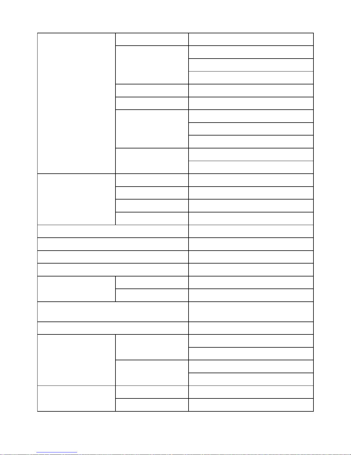
1. Monitor Specifications
Driving system TFT Color LCD
LPL:LM170E01 TLB4
Hydis:HT17E13-100
Panel type
CPT: CLAA170EA 07
Size 43.27cm (17.0")
Pixel pitch 0.264mm(H) x 0.264mm(V)
LPL Panel:140˚ (H) 140˚ (V)
Hydis panel:150˚ (H) 140˚ (V)
Viewable angle
CPT panel:140˚ (H) 130˚ (V)
LPL Panel:8 ms
LCD Panel
Response time (typ.)
Hydis & CPT panel:12 ms
Video Analog Only
Sync. Type H/V TTL Separate and Composite Sync.
H-Frequency 30kHz – 80kHz
Input
V-Frequency 56 - 75Hz
Display Colors 16.2 M
Dot Clock 135MHz (max.)
Max. Resolution 1280 x 1024
Plug & Play VESA DDC2B
On Mode <35W
Power Consumption
Power Saving <2W
Maximum Screen Size
Horizontal: 358.5mm
Vertical: 296.5mm
Power Source 90~264VAC, 47~63Hz
Temp.: 5°C to 40°C
Operating
Humidity: 10% to 80%
Temp.: -20°C to +60°C
Environmental Considerations
Storage/shipping
Humidity: 5% to 90%
Packaged 5.8Kgs Unit
Weight (N. W.)
Unpackaged 4.6Kgs Unit
Dell E173FPc
6
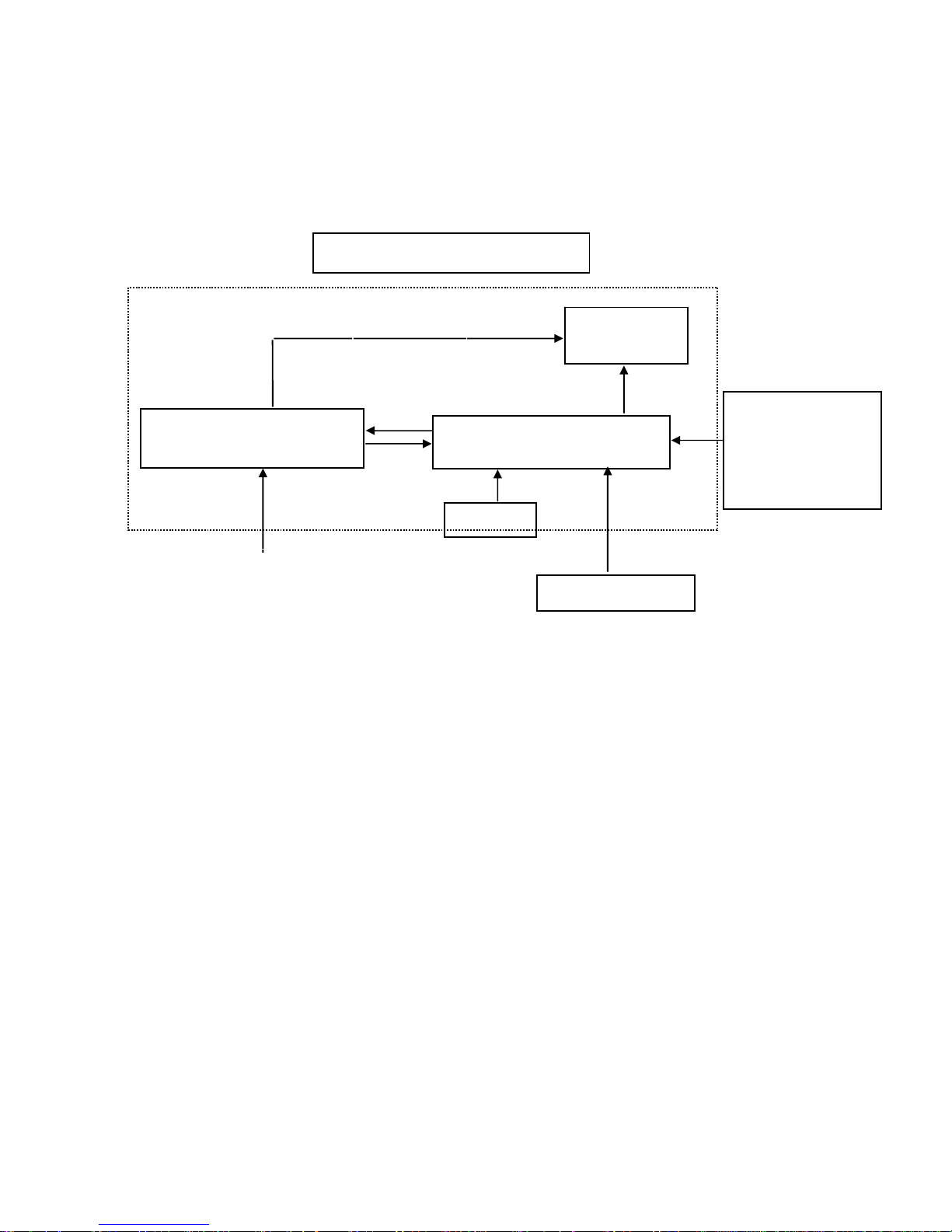
2. LCD Monitor Description
The LCD MONITOR will contain a main board, an inverter/power board, keypad board, which house the flat
panel control logic, brightness control logic and DDC.
The power board will provide AC to DC Inverter voltage to drive the backlight of panel and the main board chips
each voltage.
Monitor Block Diagram
Video signal, DDC
Power board
(
Include: inverter and adapter)
Flat Panel and
CCFL backlight
Main Board
Keyboard
RS232 Connector
For white balance
adjustment in factory
mode
CCFL Drive.
AC-IN
100V-240V
HOST Computer
Dell E173FPc
7
3. Operation instructions
3.1 General Instructions
Press the power button to turn the monitor on or off. The other control buttons are located at front panel of the
monitor. By changing these setting s, the picture ca n be adjusted to your personal preferences.
-
The power cord should be connected.
-
Connect the video cable from the monitor to the video card.
-
Press the power button to turn on the monitor, the power indicator will light up.
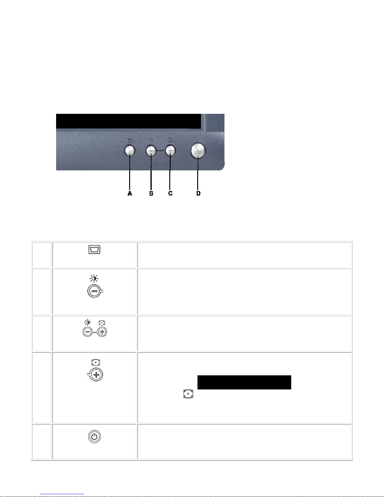
3.2 Control Buttons
A
Menu button
B
Brightness / Contrast Hotkey and - button
C
Auto Adjust and + button
D
Power On/Off button with LED Indicator
A
MENU
The 'MENU' button is used to open the on-screen display (OSD), select function
icons, exit from menus and sub-menus, and to exit the OSD. See
B
Brightness/Contrast Hot Key
Use this button for direct access to the 'Brightness' and 'Contrast' control menu.
B C
- And + buttons
Use these buttons to adjust (decrease/increase ranges) items in the OSD.
C
Auto Adjust
Use this button to activate automatic setup and adjustment. The following dialog
will appear on screen as the monitor self-adjusts to the current input:
Auto Adjust In Progress
Auto Adjustment button allows the monitor to self-adjust to the incoming
video signal. After using 'Auto Adjustment', you can further tune your monitor by
using the 'Pixel Clock' and 'Phase' controls in the OSD.
D
Power Button & Indicator
The green LED indicates the monitor is on and fully functional. An amber LED
indicates DPMS power save mode.
The Power button turns the monitor on and off.
Dell E173FPc
8
3.3 On Screen Menu/Display (OSD)
Direct-Access Functions
Function Adjustment Method
Auto adjustment
Use this button to activate automatic setup and adjustment. The
following dialog will appear on screen as the monitor self-adjusts
to the current input:
Auto Adjust In Progress
Auto Adjustment button allows the monitor to self-adjust to
the incoming video signal. After using 'Auto Adjustment', you can
further tune your monitor by using the 'Pixel Clock' and 'Phase'
controls in the OSD.
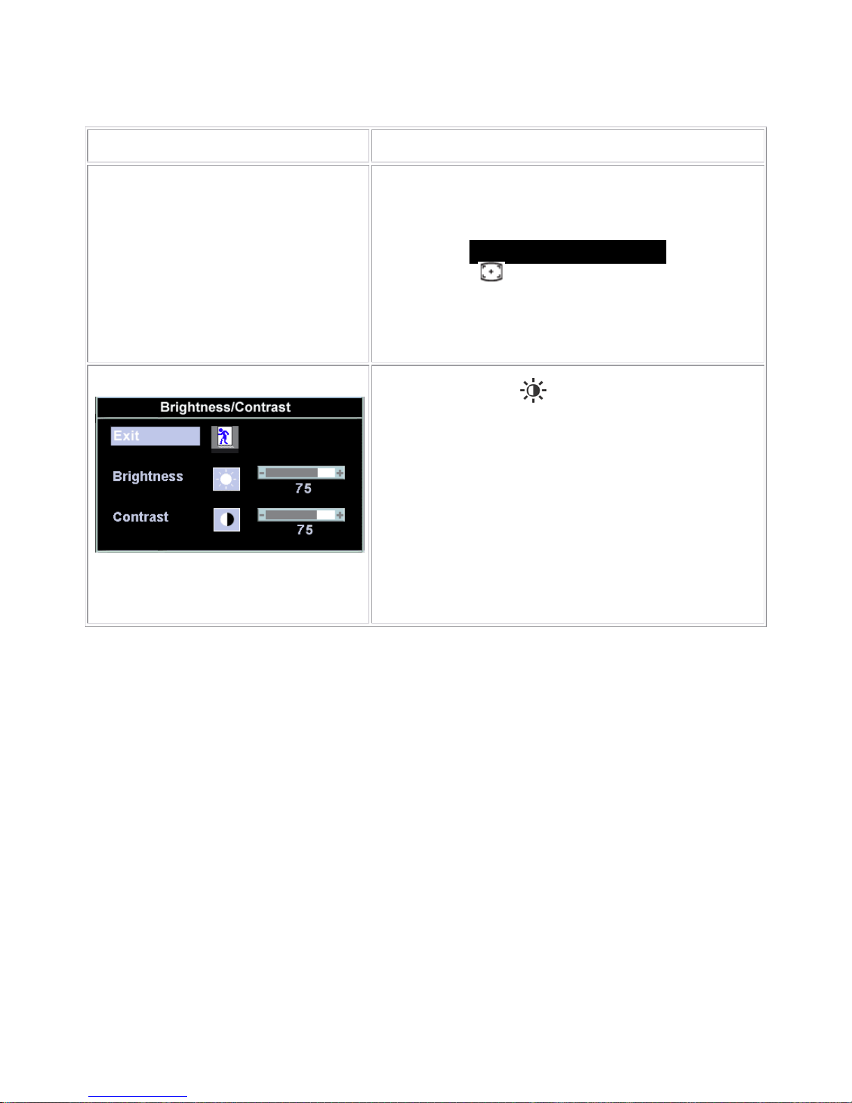
Brightness / Contrast
With the menu off, push
button to display the 'Brightness' and
'Contrast' adjustment menu.
The 'Brightness' function adjusts the luminance of the flat panel.
Adjust 'Brightness' first, and then adjust 'Contrast' only if further
adjustment is necessary.
"+" Increase 'brightness';" - "decrease 'brightness'
The 'Contrast' function adjusts the degree of diff erence between
darkness and lightness on the display screen.
"+" Increase the 'contrast'; "-" decrease the 'contrast'
Dell E173FPc
9
3.4 Adjusting the Picture
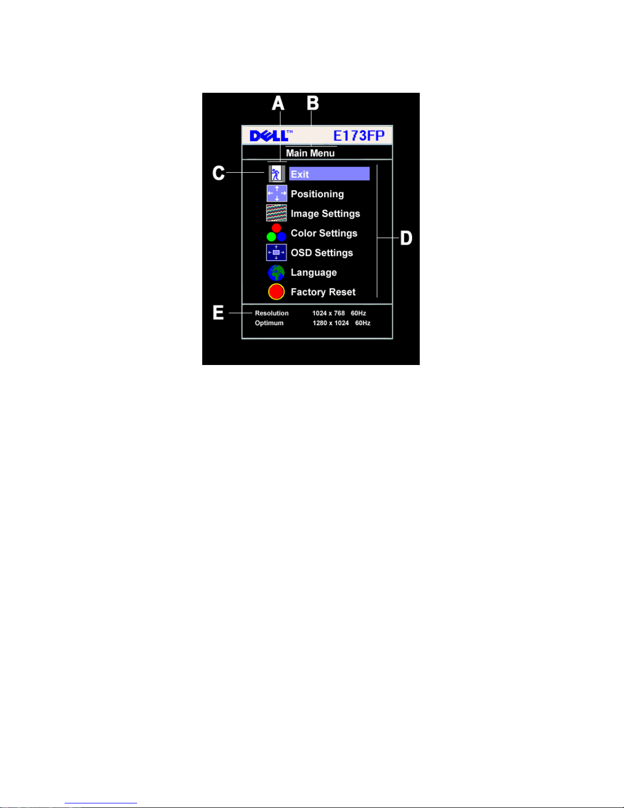
1. With the menu off, push the 'MENU' button to open the OSD system and display the main features menu.
A
Function icons
B
Main Menu
C
Menu icon
D
Sub-Menu name
E
Resolution
2. Push the - and + buttons to move between the function icons. As you move from one icon to another, the
function name is highlighted to reflect the function or group of functions (sub-menus) represented by that
icon. See the table below for a complete list of all the functions available for the monitor.
3. Push the 'MENU' button once to activate the highlighted function; Push -/+ to select the desired parameter,
push menu to enter the slide bar. then use the - and + buttons, according to the indicators on the menu, to
make your changes.
4. Push the 'Menu' button once to return to the main menu to select another function or push the 'Menu'
button two or three times to exit from the OSD.

Dell E173FPc
10
Icon
Menu Name and
Sub-menus
Description
EXIT
This is used to exit out of the 'Main menu'.
Positioning:
Horizontal
Vertical
'Positioning' moves the viewing area around on the monitor screen.
When making changes to either the 'Horizontal' or 'Vertical' settings, no changes will
occur to the size of the viewing area; the image will simply be shifted in response to
your selection/change.
Minimum is '0' (-). Maximum is '100' (+).
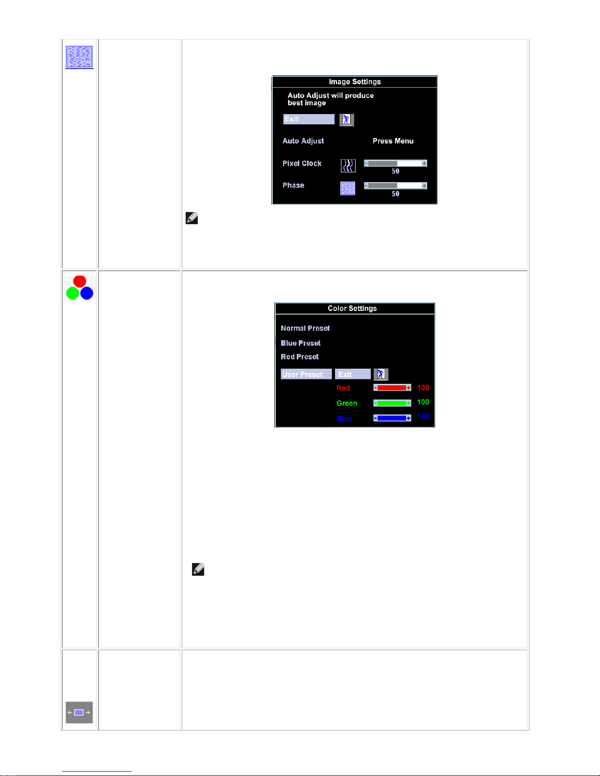
Image settings:
Auto Adjust
Even though your computer system can recognize your new flat panel monitor on
startup, the 'Auto Adjustment ' function will optimize the display settings for use with
your particular setup.
NOTE: In most cases, 'Auto Adjust' will produce the best image for your
configuration; this function can be directly access via Auto Adjustment
hotkey.
Pixel Clock
The 'Phase' and 'Pixel Clock' adjustments allow you to more closely adjust your
monitor to your preference. These settings are accessed through the main OSD
menu, by selecting 'Image Settings'.
Use the - and + buttons to adjust away interference. Minimum: 0 ~ Maximum: 100
Dell E173FPc
11
Phase
If satisfactory results are not obtained using the 'Phase' adjustment, use the 'Pixel
Clock' adjustment and then use 'Phase' again.
NOTE: This function may change the width of the display image. Use the
'Horizontal' function of the 'Position' menu to center the display image on the
screen.
Color Settings:
'Color Settings' adjusts the color temperature and saturation.
Normal Preset
'Normal Preset' is selected to obtain the default (factory) color settings.
Blue Preset
'Blue Preset' is selected to obtain a bluish tint. This color setting is typically used for
text based applications (Spreadsheets, Programming, Text Editors etc.).
Red Preset
'Red Preset' is selected to obtain a redder tint. This color setting is typically used for
color intensive applications (Photograph Image Editing, Multimedia, Movies etc.).
User Preset
'User Preset': Use the plus and minus buttons to increase or decrease each of the
three colors (R, G, B) independently, in single digit increments, from '0' to '100'.
NOTE: 'Color temperature' is a measure of the 'warmth' of the image colors
(red/green/blue). The two available preset s ('Blue' and ' Red') favo r blue an d
red accordingly. Select each one to see how each range suits your eye; or
utilize the 'User Preset' option to customize the color settings to your exact
choice.
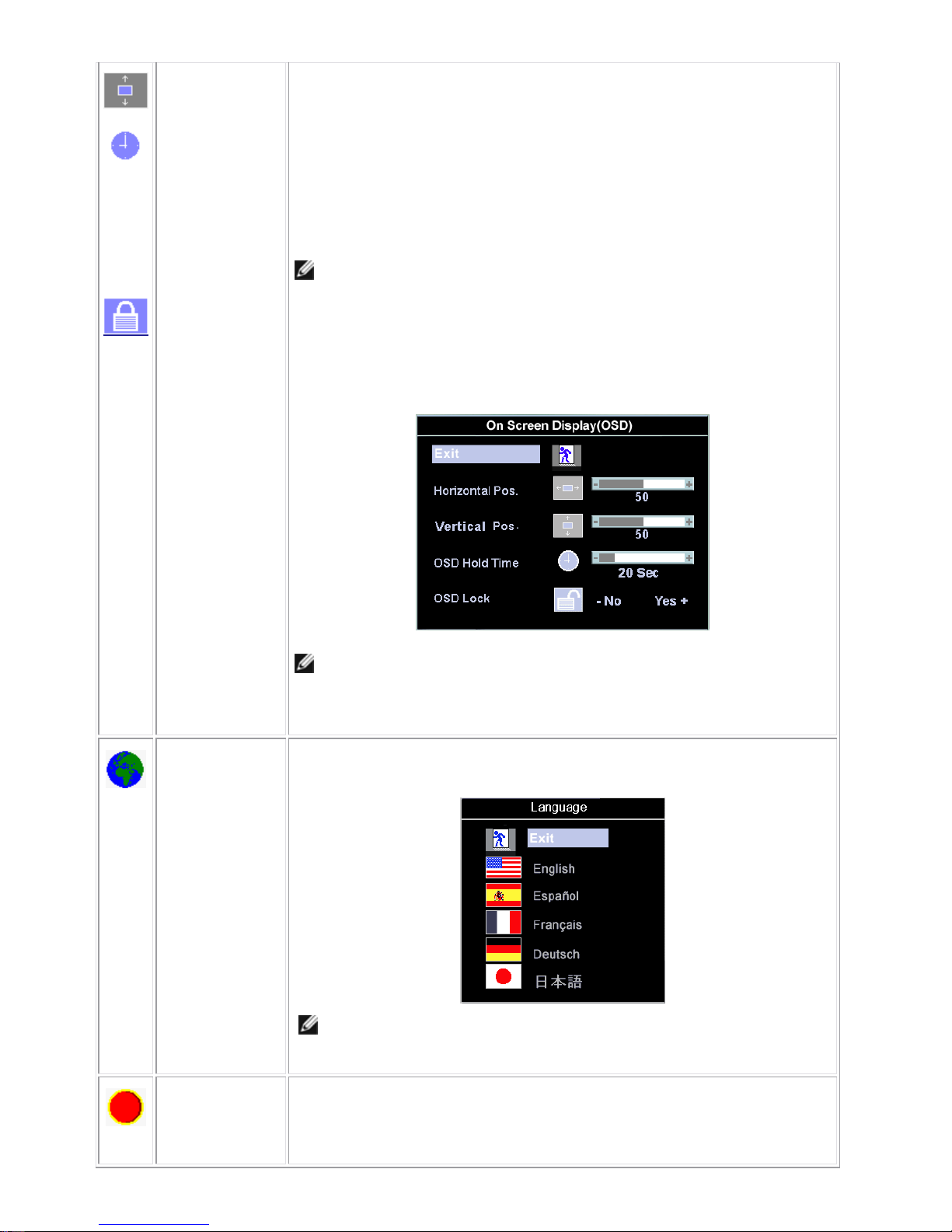
OSD Settings:
Each time the OSD opens, it displays in the same location on the screen. 'OSD
Settings' (horizontal/vertical) provides control over this location.
Horizontal
Position
- and + buttons move OSD to the left and right.
Dell E173FPc
12
Vertical Position
- and + buttons move OSD down and up.
OSD Hold Time:
The OSD stays active for as long as it is in use.
'OSD Hold Time': Sets the length of time the OSD will remain active af ter the last time
you pressed a button.
Use the - and + buttons to adjust the slider in 5 second increments, from 5 to 60
seconds.
NOTE: Default 'OSD hold time' is 20 seconds.
OSD Lock
'OSD Lock': Controls user access to adjustments. When 'Yes' (+) is selected, no user
adjustments are allowed. All buttons are locked except the menu button.
All buttons can be locked or unlocked when the 'Menu' button is pushed and held for
over 15 seconds.
NOTE: When the OSD is locked, pressing the 'Menu' button will take the user
directly to the 'OSD settings' menu, with 'OSD Lock' pre-selected on entry.
Select ‘No’ (-) to unlock and allow user access to all applicable sett ings.
Language:
Language sets the OSD to display in one of five languages (English, Español,
Français, Deutsch, Japanese).
NOTE: The language chosen affects only the language of the OSD. It has no
effect on any software running on the co mputer.
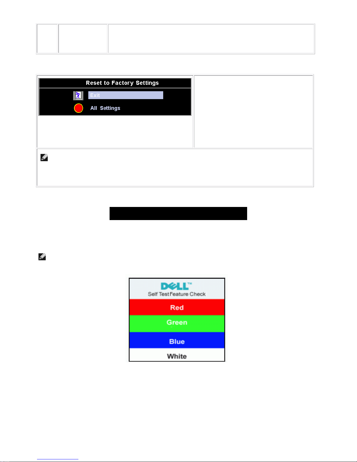
Factory Reset:
'Factory Reset' returns the settings to the factory-preset values for the selected
group of functions.
‘Exit’ is used to exit out of 'Factory Reset' menu.
Dell E173FPc
13
For 'All settings', all user adjustable settings are reset at one time except 'Language
settings'.
Reset Functions
Factory Preset Restoration
'Exit' leaves this submenu without resetting any
values.
'All Settings' returns your monitor settings to
those that were set at the time of manufacture.
This includes 'Color', 'Position', 'Clock
frequency', 'Phase', 'Brightness', 'Contrast' and
'OSD hold time'.
NOTE: There is no "Undo" when you use the 'Reset function'. To return to the previous function settings,
you must adjust the functions again. 'Reset' will set the clock and phase back to factory settings, activating
auto adjust may be required and this will optimize the image for your system.
OSD Warning Messages
A warning message may appear on the screen indicating that the monitor is out of sync.
Cannot Display This Video Mode
This means that the monitor cannot synchronize with the signal that it is receiving from the computer. Either the
signal is too high or too low for the monitor to use. See Specifications for the Horizontal and Vertical frequency
ranges addressable by this monitor. Recommended mode is 1280 X 1024 @ 60Hz.
NOTE: The floating 'Dell - self-test Feature Check' dialog will appear on-screen if the monitor cannot sense a
video signal.
Occasionally , no warning messag e appears, but the screen is blank. This could al so indicate that the monitor is not
synchronizing with the computer. See Troubleshooting for more information.
Dell E173FPc
14
4. Input/Output Specification
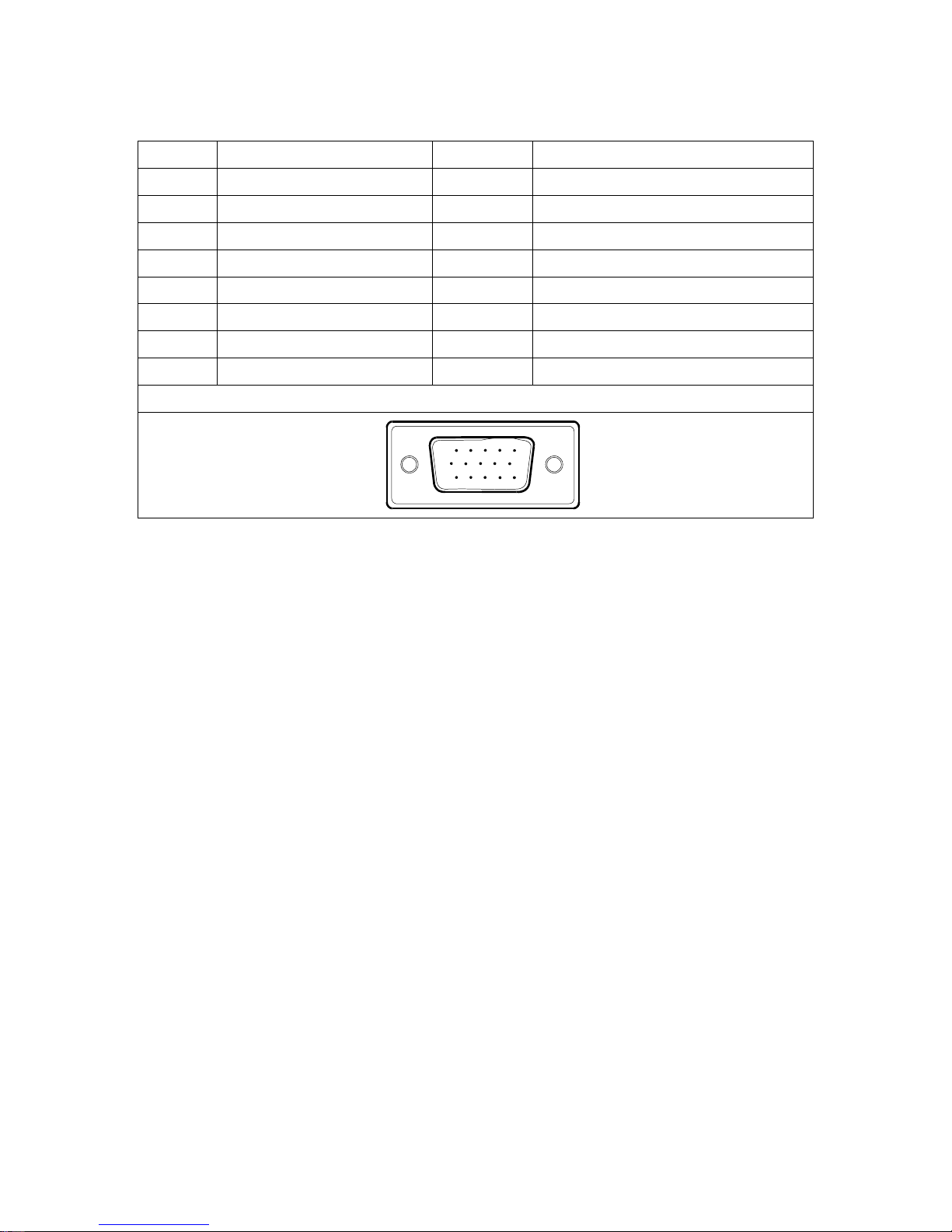
4.1 Input Signal Connector
PIN NO. DESCRIPTION PI N NO. DESCRIPTION
1. Red Video 9. +5V (From PC)
2. Green Video 10. Detect Pin
3. Blue Video 11. RXD
4. TXD 12. DDC-Serial Data
5. DDC-Return 13. H-Sync
6. R-Ground 14. V-Sync
7. G-Ground 15. DDC-Serial Clock
8. B-Ground
VGA Connect or layout
15
6
10
11 15
Dell E173FPc
15
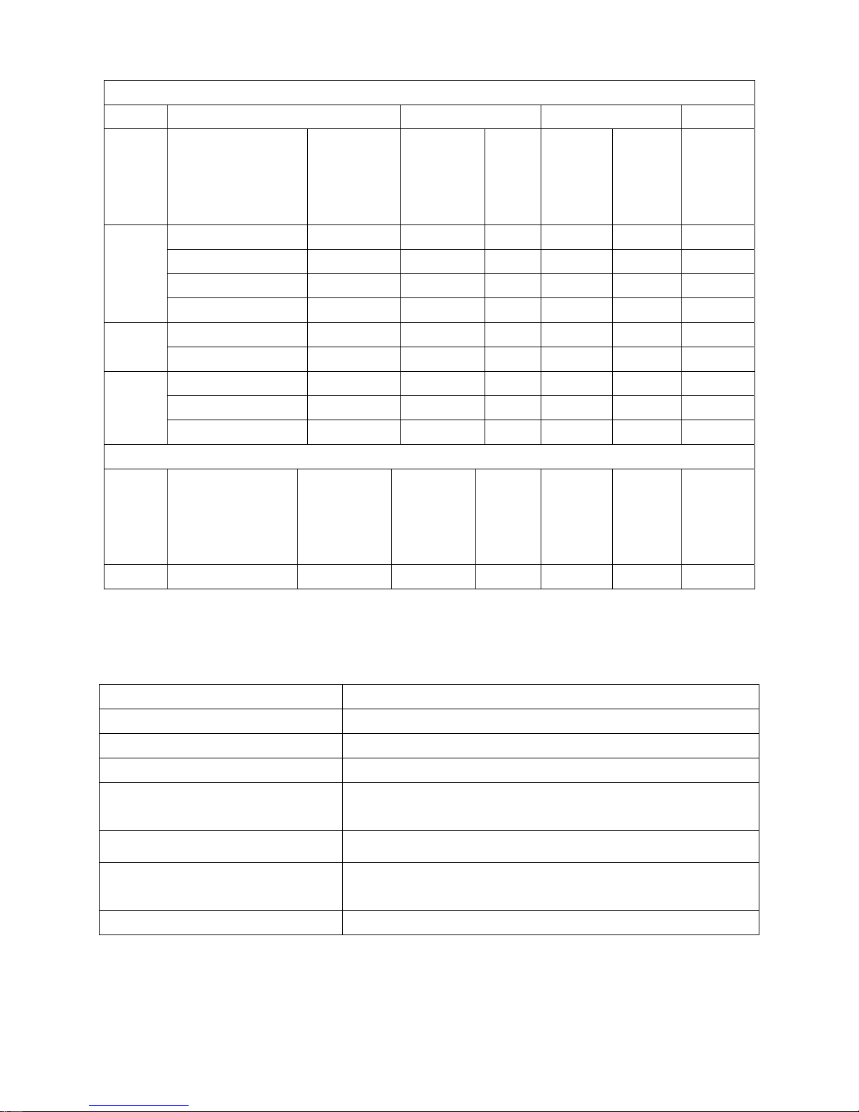
4.2 Factory Preset Display Modes
VESA MODES
Horizontal Vertical
Mode Resolution Total
Nominal
Frequency
+/- 0.5kHz
Sync
Polarit
y
Nominal
Freq.
+/- 1 Hz
Sync
Polarity
Nominal
Pixel
Clock
(MHz)
640x480@60Hz 800 x 525 31.469 N 59.940 N 25.175
640x480@75Hz 840 x 500 37.500 N 75.00 N 31.500
800x600@60Hz 1056 x 628 37.879 P 60.317 P 40.000
VGA
800x600@75Hz 1056x625 46.875 P 75.000 P 49.500
1024x768@60Hz 1344x806 48.363 N 60.004 N 65.000
XGA
1024x768@75Hz 1312x800 60.023 P 75.029 P 78.750
1152x864@75Hz 1600x900 67.500 P 75.000 P 108.00
1280x1024@60Hz 1688x1066 64.000 P 60.000 P 108.00
SXGA
1280x1024@75Hz 1688x1066 79.976 P 75.025 P 135.00
IBM MODES
Mode Resolution Total
Nominal
Frequency
+/- 0.5kHz
Sync
Polarity
Nominal
Freq.
+/- 1 Hz
Sync
Polarity
Nominal
Pixel
Clock
(MHz)
DOS 720x400@70Hz 900 x 449 31.469 N 70.087 P 28.322
4.3 Power Supply Requirements
A/C Line voltage range : 100 V ~ 240 V± 10 %
A/C Line frequency range
: 50 ± 3Hz, 60 ± 3Hz
Input Volt age transients
: 280 volts AC for 10 sec @40℃
Current : 0.6A max. at 100V, 0.35A max. at 240 V
Peak surge current : < 60A peak at 240 VAC and cold starting
: < 30A peak at 120VAC and cold starting
Leakage current : < 3.5mA
Power line surge : No advance effects (no loss of information or defe ct)
with a maximum of 1 half-wave missing per second
Power Consumption : Power-On, <35W; Power-saving, < 2W
Dell E173FPc
16
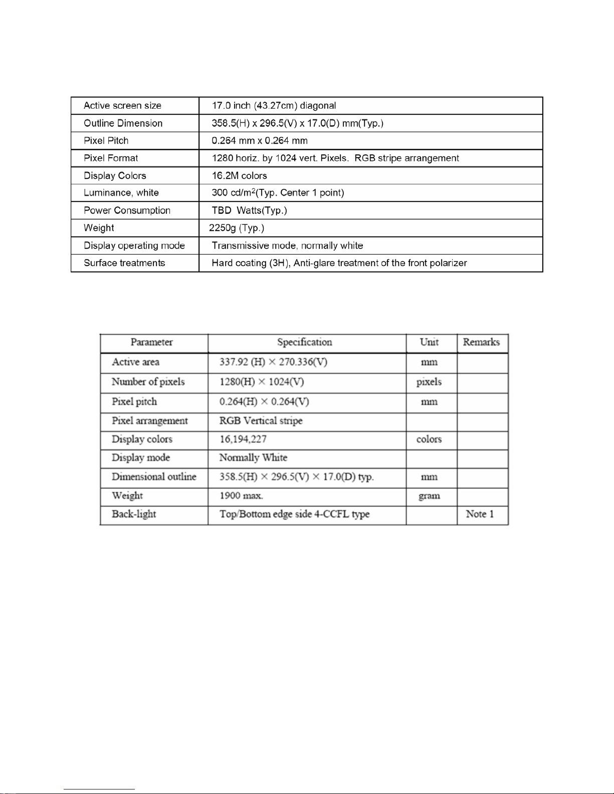
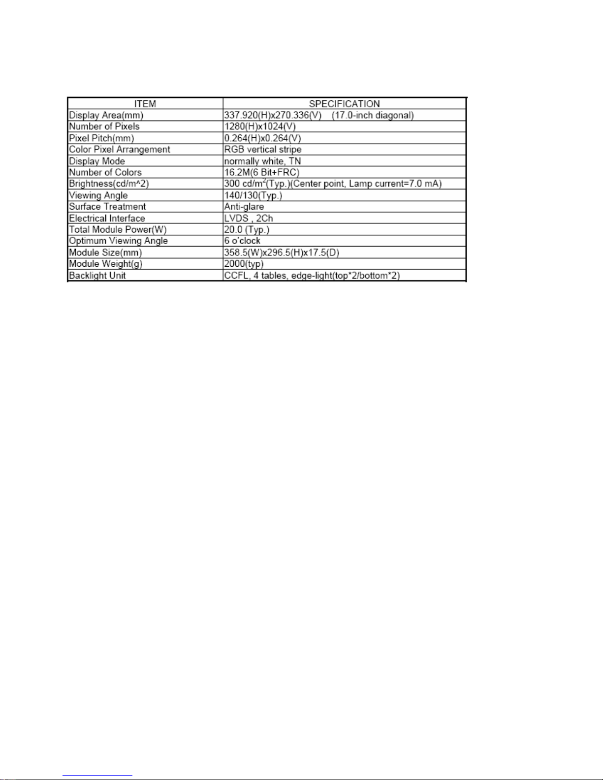
4.4 Panel Specification
4.4.1 Display Characteristics
For LPL panel
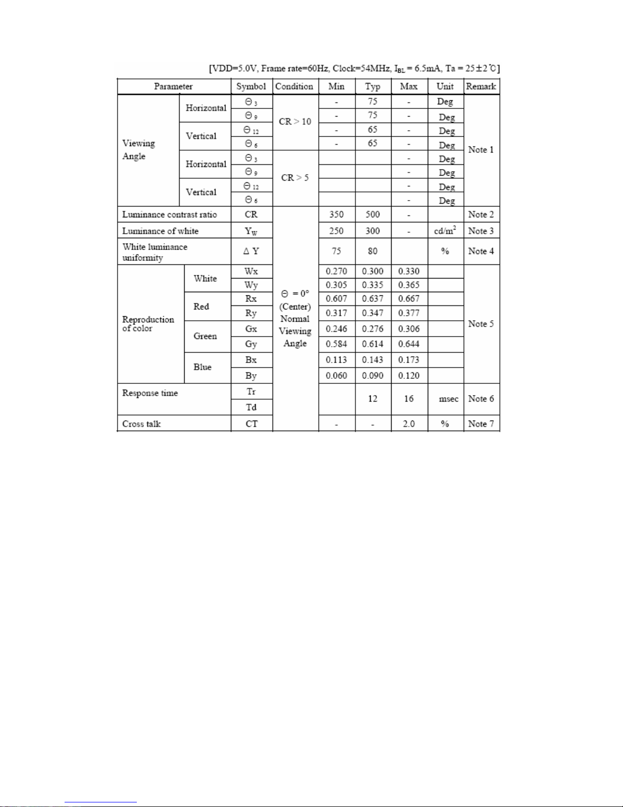
For Hydis panel
Dell E173FPc
17
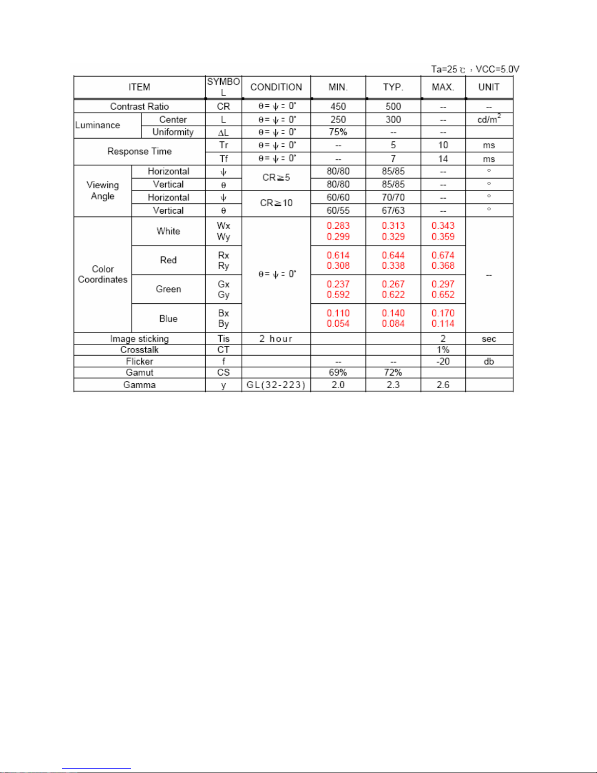
Display Characteristics
For CPT panel
Dell E173FPc
18
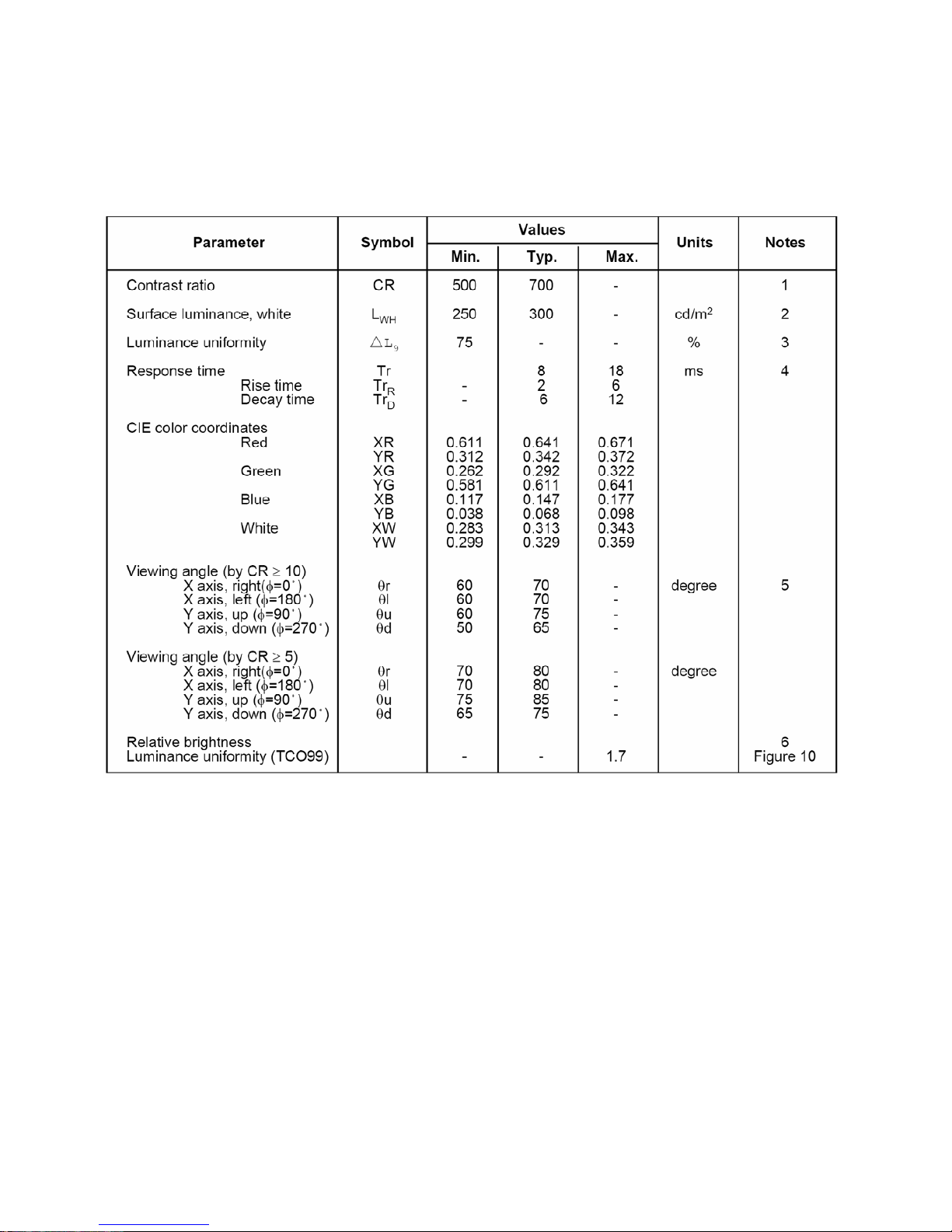
4.4.2 Optical Characteristics
For LPL panel
The optical characteristics are measured under stable conditions as follows:
Measuring surrounding:
Ta=25ºC ,Vcc=5.0V,Fv=60Hz,IBL=6.5mArms
Dell E173FPc
19
For Hydis panel
Dell E173FPc
20
For CPT panel
Dell E173FPc
21
5. Block Diagram
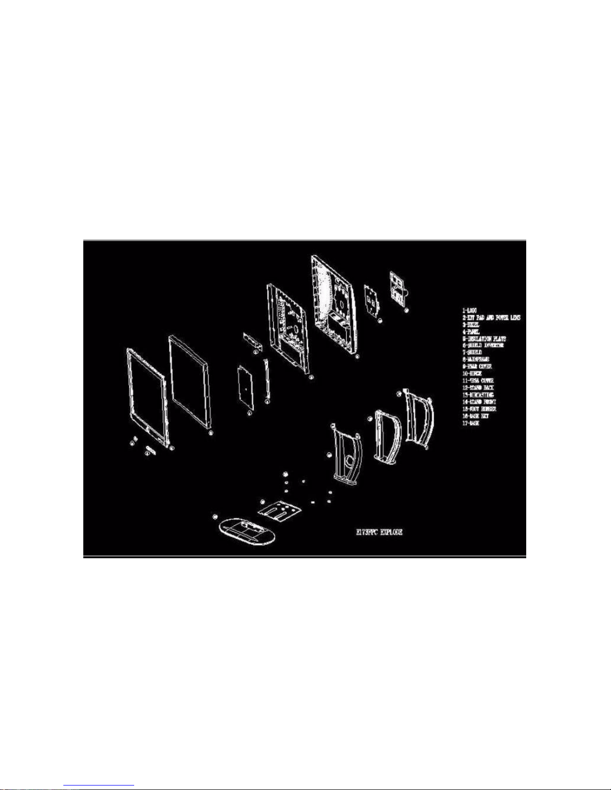
5.1 Exploded View
Dell E173FPc
22
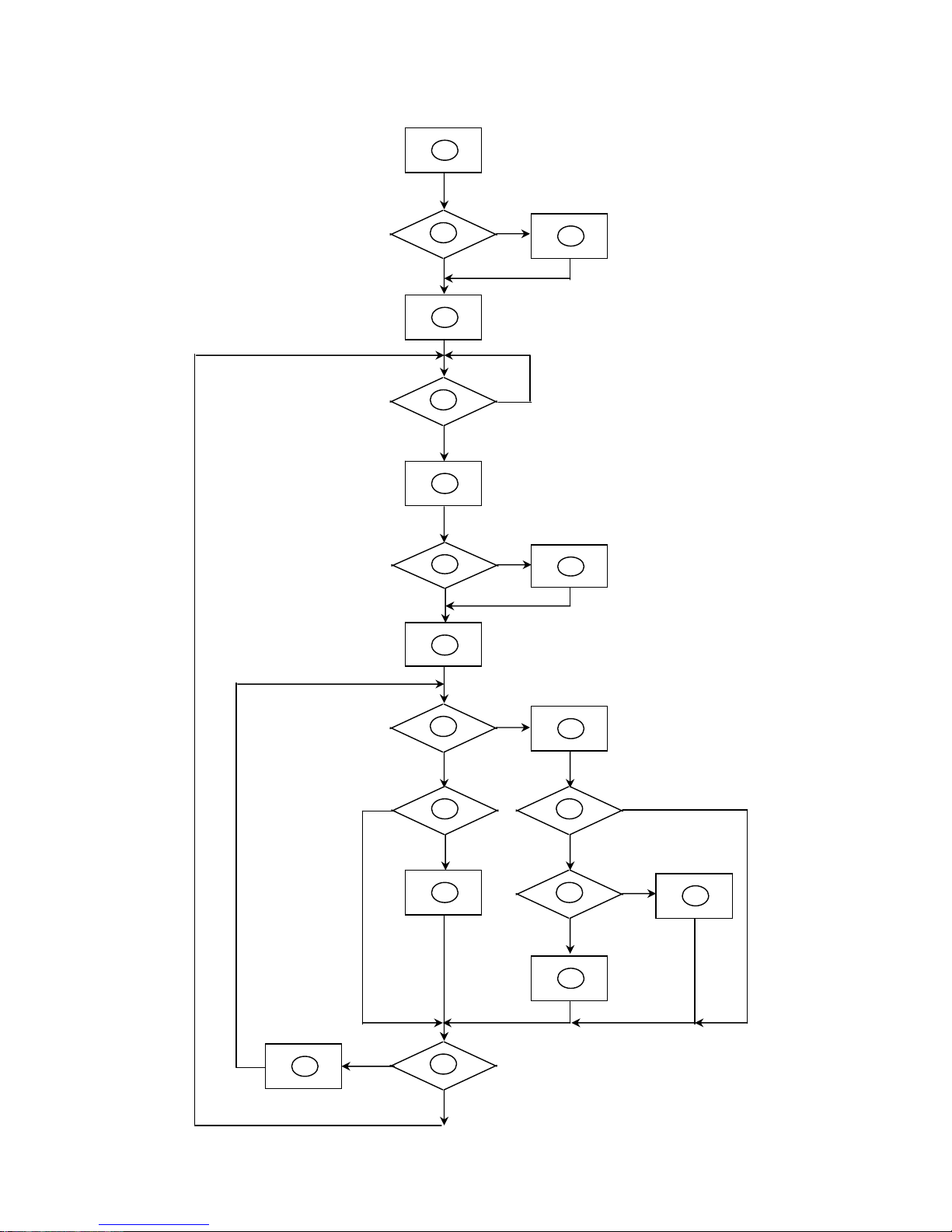
5.2 Software Flow Chart
2
N
Y
5
Y
N
10
Y
N
12
Y
N
7
Y
N
6
4
3
8
9
14
11
13
Y
N
15
Y
N
16
17
19
Y
N
18
 Loading...