

Page 1

Alienware Aurora-R4
Owner’s Manual
Regulatory model: D01M
Regulatory type: D01M004
www.dell.com | support.dell.com/manuals
Page 2

Notes, Cautions, and Warnings
NOTE: A NOTE indicates important information that helps you make better
use of your product.
CAUTION: A CAUTION indicates either potential damage to hardware or
loss of data, and tells you how to avoid the problem.
WARNING: A WARNING indicates a potential for property damage,
personal injury, or death.
____________________
Information in this document is subject to change without notice.
© 2011 Dell Inc. All rights reserved.
Reproduction of these materials in any manner whatsoever without the written permission of Dell Inc.
is strictly forbidden.
®
Trademarks used in this text: Dell™ and the DELL logo are trademarks of Dell Inc. Alienware
registered trademark of Alienware Corporation. Microsoft
logo are either trademarks or registered trademarks of Microsoft Corporation in the United States and/
or other countries.
Other trademarks and trade names may be used in this document to refer to either the entities claiming
the marks and names or their products. Dell Inc. disclaims any proprietary interest in trademarks and
trade names other than its own.
2011 - 12 Rev. A00
®
, Windows®, and the Windows start button
is a
Page 3

Contents
1 Before You Begin. . . . . . . . . . . . . . . . . . . 13
Turn Off Your Computer and Connected Devices . . . . 13
Safety Instructions
Recommended Tools. . . . . . . . . . . . . . . . . . . 14
. . . . . . . . . . . . . . . . . . . . 13
2 After Working Inside Your Computer. . . . 15
3 Technical Overview . . . . . . . . . . . . . . . . . 17
Front View of Your Computer . . . . . . . . . . . . . . 17
Back View of Your Computer
Inside View of Your Computer
System-Board Components . . . . . . . . . . . . . . . 20
Master I/O Board Components
Top Lighting-Board Components
. . . . . . . . . . . . . . 18
. . . . . . . . . . . . . . 19
. . . . . . . . . . . . . 21
. . . . . . . . . . . . 23
4 Left Side-Panel . . . . . . . . . . . . . . . . . . . . 25
Removing the Left Side-Panel . . . . . . . . . . . . . . 25
Replacing the Left Side-Panel
. . . . . . . . . . . . . . 27
Contents 3
Page 4

5 Hard Drive(s) . . . . . . . . . . . . . . . . . . . . . 29
Prerequisites . . . . . . . . . . . . . . . . . . . . . . . 29
Removing the Hard Drive(s)
. . . . . . . . . . . . . . . 29
Replacing the Hard Drive(s) . . . . . . . . . . . . . . . 30
Postrequisites
. . . . . . . . . . . . . . . . . . . . . . 30
6 Hard-Drive Fan Assembly . . . . . . . . . . . 33
Prerequisites . . . . . . . . . . . . . . . . . . . . . . . 33
Removing the Hard-Drive Fan Assembly . . . . . . . . 33
Replacing the Hard-Drive Fan Assembly
Postrequisites
. . . . . . . . . . . . . . . . . . . . . . 35
. . . . . . . . 34
7 Optical Drive(s) . . . . . . . . . . . . . . . . . . . 37
Prerequisites . . . . . . . . . . . . . . . . . . . . . . . 37
Removing the Optical Drive(s) . . . . . . . . . . . . . . 37
Replacing the Optical Drive(s)
. . . . . . . . . . . . . . 38
8 Media-Card Reader . . . . . . . . . . . . . . . . 41
4 Contents
Postrequisites
. . . . . . . . . . . . . . . . . . . . . . 38
Prerequisites . . . . . . . . . . . . . . . . . . . . . . . 41
Removing the Media-Card Reader
Replacing the Media-Card Reader
. . . . . . . . . . . . 41
. . . . . . . . . . . 43
Page 5

Postrequisites . . . . . . . . . . . . . . . . . . . . . . 44
9 PCI Shroud. . . . . . . . . . . . . . . . . . . . . . . . 45
Prerequisites. . . . . . . . . . . . . . . . . . . . . . . 45
Opening the PCI Shroud
. . . . . . . . . . . . . . . . . 45
Closing the PCI Shroud . . . . . . . . . . . . . . . . . 46
Postrequisites
. . . . . . . . . . . . . . . . . . . . . . 46
10 Drive-Bay Shroud . . . . . . . . . . . . . . . . . . 47
Prerequisites. . . . . . . . . . . . . . . . . . . . . . . 47
Removing the Drive-Bay Shroud . . . . . . . . . . . . 47
Replacing the Drive-Bay Shroud
Postrequisites
. . . . . . . . . . . . . . . . . . . . . . 48
. . . . . . . . . . . . 48
11 PCI-Express x1 Card . . . . . . . . . . . . . . . . 49
Prerequisites. . . . . . . . . . . . . . . . . . . . . . . 49
Removing the PCI-Express x1 Card
Replacing the PCI-Express x1 Card
. . . . . . . . . . . 49
. . . . . . . . . . . 50
Postrequisites
. . . . . . . . . . . . . . . . . . . . . . 51
12 PCI-Fan . . . . . . . . . . . . . . . . . . . . . . . . . . 53
Prerequisites. . . . . . . . . . . . . . . . . . . . . . . 53
Contents 5
Page 6

Removing the PCI-Fan . . . . . . . . . . . . . . . . . . 53
Replacing the PCI-Fan
Postrequisites
. . . . . . . . . . . . . . . . . . 54
. . . . . . . . . . . . . . . . . . . . . . 55
13 Graphics Card . . . . . . . . . . . . . . . . . . . . 57
Prerequisites . . . . . . . . . . . . . . . . . . . . . . . 57
Removing the Graphics Card
Replacing the Graphics Card
. . . . . . . . . . . . . . . 57
. . . . . . . . . . . . . . 58
Postrequisites . . . . . . . . . . . . . . . . . . . . . . 59
Installing Dual Graphic Cards
Connect the Display
. . . . . . . . . . . . . . 59
. . . . . . . . . . . . . . . . . 61
14 Memory Module(s). . . . . . . . . . . . . . . . . 63
Prerequisites . . . . . . . . . . . . . . . . . . . . . . . 63
Removing Memory Module(s)
. . . . . . . . . . . . . . 63
15 Memory Fan . . . . . . . . . . . . . . . . . . . . . . 67
6 Contents
Replacing Memory Module(s) . . . . . . . . . . . . . . 64
Postrequisites
. . . . . . . . . . . . . . . . . . . . . . 66
Prerequisites . . . . . . . . . . . . . . . . . . . . . . . 67
Removing the Memory Fan
Replacing the Memory Fan
. . . . . . . . . . . . . . . . 67
. . . . . . . . . . . . . . . 68
Page 7

Postrequisites . . . . . . . . . . . . . . . . . . . . . . 68
16 Processor Liquid-Cooling Assembly . . . . 71
Prerequisites. . . . . . . . . . . . . . . . . . . . . . . 71
Removing the Processor Liquid-Cooling Assembly
. . . 71
Replacing the Processor Liquid-Cooling Assembly . . 72
Postrequisites
. . . . . . . . . . . . . . . . . . . . . . 73
17 Processor . . . . . . . . . . . . . . . . . . . . . . . . 75
Prerequisites. . . . . . . . . . . . . . . . . . . . . . . 75
Removing the Processor. . . . . . . . . . . . . . . . . 75
Replacing the Processor
Postrequisites
. . . . . . . . . . . . . . . . . . . . . . 80
. . . . . . . . . . . . . . . . 78
18 Power-Supply Unit. . . . . . . . . . . . . . . . . . 83
Prerequisites. . . . . . . . . . . . . . . . . . . . . . . 83
Removing the Power-Supply Unit
Replacing the Power-Supply Unit
. . . . . . . . . . . . 83
. . . . . . . . . . . . 86
Postrequisites
. . . . . . . . . . . . . . . . . . . . . . 87
19 Coin-Cell Battery . . . . . . . . . . . . . . . . . . . 89
Prerequisites. . . . . . . . . . . . . . . . . . . . . . . 89
Contents 7
Page 8

Removing the Coin-Cell Battery . . . . . . . . . . . . . 89
Replacing the Coin-Cell Battery
Postrequisites
. . . . . . . . . . . . . . . . . . . . . . 90
. . . . . . . . . . . . . 90
20 Theater-Lighting Batteries
(ALX Chassis Only) . . . . . . . . . . . . . . . . . 93
Prerequisites . . . . . . . . . . . . . . . . . . . . . . . 93
Removing the Theater-Lighting Batteries . . . . . . . . 93
Replacing the Theater-Lighting Batteries
Postrequisites
. . . . . . . . . . . . . . . . . . . . . . 94
. . . . . . . . 94
21 System-Board Assembly . . . . . . . . . . . . 95
Prerequisites . . . . . . . . . . . . . . . . . . . . . . . 95
Removing the System-Board Assembly
Replacing the System-Board Assembly
. . . . . . . . . 95
. . . . . . . . . 96
22 Master I/O Board . . . . . . . . . . . . . . . . . . 99
8 Contents
Postrequisites
Entering the Service Tag in BIOS
. . . . . . . . . . . . . . . . . . . . . . 97
. . . . . . . . . . . . 97
Prerequisites . . . . . . . . . . . . . . . . . . . . . . . 99
Removing the Master I/O Board
Replacing the Master I/O Board
. . . . . . . . . . . . . 99
. . . . . . . . . . . . 100
Page 9

Postrequisites . . . . . . . . . . . . . . . . . . . . . . 100
23 Top Lighting-Board . . . . . . . . . . . . . . . . 103
Prerequisites. . . . . . . . . . . . . . . . . . . . . . . 103
Removing the Top Lighting-Board
. . . . . . . . . . . . 103
Replacing the Top Lighting-Board. . . . . . . . . . . . 104
Postrequisites
. . . . . . . . . . . . . . . . . . . . . . 104
24 Right-Side Top Panel . . . . . . . . . . . . . . . 107
Prerequisites. . . . . . . . . . . . . . . . . . . . . . . 107
Removing the Right-Side Top Panel. . . . . . . . . . . 107
Replacing the Right-Side Top Panel
Postrequisites
. . . . . . . . . . . . . . . . . . . . . . 111
. . . . . . . . . . . 110
25 Right-Side Middle Panel . . . . . . . . . . . . 113
Prerequisites. . . . . . . . . . . . . . . . . . . . . . . 113
Removing the Right-Side Middle Panel
Replacing the Right-Side Middle Panel
. . . . . . . . . 113
. . . . . . . . . 114
Postrequisites
. . . . . . . . . . . . . . . . . . . . . . 115
26 Right Lighting-Board . . . . . . . . . . . . . . . 117
Prerequisites. . . . . . . . . . . . . . . . . . . . . . . 117
Contents 9
Page 10

Removing the Right Lighting-Board . . . . . . . . . . 117
Replacing the Right Lighting-Board
Postrequisites
. . . . . . . . . . . . . . . . . . . . . 119
. . . . . . . . . . 118
27 Right-Side Bottom Panel . . . . . . . . . . . . 121
Prerequisites . . . . . . . . . . . . . . . . . . . . . . 121
Removing the Right-Side Bottom Panel
Replacing the Right-Side Bottom Panel
. . . . . . . . 121
. . . . . . . . 123
Postrequisites . . . . . . . . . . . . . . . . . . . . . 124
28 Top Vent . . . . . . . . . . . . . . . . . . . . . . . . . 125
Prerequisites . . . . . . . . . . . . . . . . . . . . . . 125
Removing the Top Vent
Replacing the Top Vent
Postrequisites . . . . . . . . . . . . . . . . . . . . . 128
. . . . . . . . . . . . . . . . . 125
. . . . . . . . . . . . . . . . . 127
29 Front Bezel. . . . . . . . . . . . . . . . . . . . . . . 129
10 Contents
Prerequisites . . . . . . . . . . . . . . . . . . . . . . 129
Removing the Front Bezel
Replacing the Front Bezel
Postrequisites
. . . . . . . . . . . . . . . . . . . . . 132
. . . . . . . . . . . . . . . 129
. . . . . . . . . . . . . . . 131
Page 11

30 Back Bezel. . . . . . . . . . . . . . . . . . . . . . . 133
Prerequisites. . . . . . . . . . . . . . . . . . . . . . . 133
Removing the Back Bezel
. . . . . . . . . . . . . . . . 133
Replacing the Back Bezel . . . . . . . . . . . . . . . . 136
Postrequisites
. . . . . . . . . . . . . . . . . . . . . . 136
31 WiFi/Bluetooth Assembly . . . . . . . . . . . 137
Prerequisites. . . . . . . . . . . . . . . . . . . . . . . 137
Removing the WiFi/Bluetooth Card . . . . . . . . . . . 137
Replacing the WiFi/Bluetooth Card
Postrequisites
. . . . . . . . . . . . . . . . . . . . . . 138
. . . . . . . . . . . 138
32 Top I/O Panel . . . . . . . . . . . . . . . . . . . . . 141
Prerequisites. . . . . . . . . . . . . . . . . . . . . . . 141
Removing the Top I/O Panel . . . . . . . . . . . . . . . 141
Replacing the Top I/O Panel
. . . . . . . . . . . . . . . 142
Postrequisites
. . . . . . . . . . . . . . . . . . . . . . 143
33 System Setup . . . . . . . . . . . . . . . . . . . . . 145
Overview . . . . . . . . . . . . . . . . . . . . . . . . . 145
Entering System Setup
System Setup Screens
System Setup Options
. . . . . . . . . . . . . . . . . . 145
. . . . . . . . . . . . . . . 145
. . . . . . . . . . . . . . . 146
Contents 11
Page 12

Boot Sequence . . . . . . . . . . . . . . . . . . 152
Clearing Forgotten Passwords
Password:
. . . . . . . . . . . . . . . . . . . . . . . . . . 155
. . . . . . . . . . . . . . . . . . . . . 155
Clearing CMOS Passwords
. . . . . . . . . . . . . . . . . . . . . . . 156
CMOS:
. . . . . . . . . . . . . 154
. . . . . . . . . . . . . . 156
34 Flashing the BIOS . . . . . . . . . . . . . . . . . 159
35 Specifications . . . . . . . . . . . . . . . . . . . . 161
12 Contents
Page 13

3
Before You Begin
Turn Off Your Computer and Connected Devices
CAUTION: To avoid losing data, save and close all open files and exit all open
programs before you turn off your computer.
1
Save and close all open files and exit all open programs.
2
Click
Start
and click
Microsoft Windows shuts down and then the computer turns off.
NOTE: If you are using a different operating system, see the documentation of
your operating system for shut-down instructions.
3
Disconnect your computer and all attached devices from their electrical
outlets.
4
Disconnect all telephone cables, network cables, and attached devices
from your computer.
5
Press and hold the power button, while the computer is unplugged, to
ground the system board.
Shut Down
.
Safety Instructions
Use the following safety guidelines to protect your computer from potential
damage and ensure your personal safety.
WARNING: Before working inside your computer, read the safety information
that shipped with your computer. For additional safety best practices information,
see the Regulatory Compliance Homepage at dell.com/regulatory_compliance.
CAUTION: To avoid damaging the computer, ensure that the work surface is flat
and clean.
CAUTION: To avoid damaging the components and cards, handle them by their
edges and avoid touching pins and contacts.
WARNING: Disconnect all power sources before opening the computer cover or
panels. After you finish working inside the computer, replace all covers, panels,
and screws before connecting to the power source.
Before you Begin 13
Page 14

CAUTION: Only a certified service technician is authorized to remove the
computer cover and access any of the components inside the computer. See the
safety instructions for complete information about safety precautions, working
inside your computer, and protecting against electrostatic discharge.
CAUTION: Before touching anything inside your computer, ground yourself by
touching an unpainted metal surface, such as the metal at the back of the
computer. While you work, periodically touch an unpainted metal surface to
dissipate static electricity, which could harm internal components.
CAUTION: When you disconnect a cable, pull on its connector or on its pull-tab,
not on the cable itself. Some cables have connectors with locking tabs or
thumb-screws that you must disengage before disconnecting the cable. When
disconnecting cables, keep them evenly aligned to avoid bending any connector
pins. When connecting cables, ensure that the connectors and ports are correctly
oriented and aligned.
CAUTION: To disconnect a network cable, first unplug the cable from your
computer and then unplug the cable from the network device.
Recommended Tools
The procedures in this document may require the following tools:
• Small Phillips screwdriver
•Hex nut driver
• Flash BIOS executable update program available at
support.dell.com
14 Before you Begin
Page 15
4
After Working Inside Your Computer
After you complete replacement procedures, ensure the following:
• Replace all screws and ensure no stray screws remain inside your computer
• Connect any external devices, cables, cards, and any other part you
removed before working on your computer
• Connect your computer and all attached devices to their electrical outlets
CAUTION: Before turning on your computer, replace all screws and ensure that
no stray screws remain in the computer. Failure to do so may damage your
computer.
• Turn on your computer.
After Working Inside Your Computer 15
Page 16

16 Before you Begin
Page 17

Technical Overview
7
1
8
11
9
10
2
3
4
5
6
WARNING: Before working inside your computer, read the safety information
that shipped with your computer and follow the steps in "Before You Begin" on
page 13. For additional safety best practices information, see the Regulatory
Compliance Homepage at dell.com/regulatory_compliance.
Front View of Your Computer
1
Technical Overview 17
Page 18

1 AlienHead/drive-panel open button 2 optical drive
1
2
3
4
5
6
7
8 9
10
11
12
3 optical-drive eject button 4 optical-drive bay
5 media-card reader/optical-drive bay 6 drive panel (open)
7 headphone connector 8 microphone connector
9 USB 3.0 connector 10 power button
11 USB 2.0 connectors (2)
Back View of Your Computer
18 Technical Overview
Page 19

1 coaxial S/PDIF connector 2 optical S/PDIF connector
1
2
3
4
3 USB 2.0 connectors (4) 4 network connector and network
lights
5 USB 3.0 connector 6 audio connectors
7 expansion-card slots 8 power connector
9 power-supply diagnostics button 10 power-supply diagnostics light
11 security-cable slot latch 12 security-cable slot
Inside View of Your Computer
1 memory module(s) 2 PCI-Express card(s)
3 optical drive(s) 4 hard-drive(s)
Technical Overview 19
Page 20
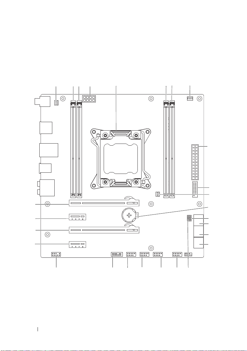
System-Board Components
1
5
9
14
15
18
19
20
21
22
23
24
25
26
27
12
6
23 4
7 8
10
13
16
11
17
20 Technical Overview
Page 21

1 heat-sink fan connector
(SYS_FAN1)
3 memory-module connector
(DIMM2)
5 processor socket (CPU1) 6 memory-module connector
7 memory-module connector
(DIMM3)
9 main power connector (PWR1) 10 front USB connector (FUSB3_0)
11 heat-sink fan connector
(SYS_FAN2)
13 CMOS jumper (CLEAR_CMOS) 14 serial ATA drive connectors
15 serial ATA drive connectors
(SATA3_4)
17 password jumper (PASSWORD) 18 front panel connector
19 USB connector (USB1) 20 USB connector (USB2)
21 USB connector (USB3) 22 Low pin count debug header (LPC)
23 front audio connector
(FRONT_AUDIO)
25 PCI-Express x16 connector
(SLOT3)
27 PCI-Express x16 connector (SLOT1)
2 memory-module connector
(DIMM1)
4 processor power connector (PWR2)
(DIMM4)
8 processor fan connector
(CPU_FAN)
12 battery socket (BAT1)
(SATA1_2)
16 serial ATA drive connectors
(SATA5_6)
(FRONT_PANEL)
24 PCI-Express x1 connector (SLOT4)
26 PCI-Express x1 connector (SLOT2)
Master I/O Board Components
NOTE: The location of the connectors may vary based on the selections you made
at the time of purchase.
Technical Overview 21
Page 22

1 FlexBay connector (FLEXBAY) 2 drive-bay shroud battery connector
9
10
12
11
1
2
3
4
5
6 7
8
131415
16
18
21
20
19
17
(FRONT_BEZEL)
3 AlienHead connector (HEAD1) 4 PCI-fan connector (FAN_PCI)
5 left side-panel contact board
connector (SIDE_L)
7 power-LED board connector
(BLINK)
6 WiFi/Bluetooth connector
(BLUETOOTH)
8 wireless connector (WIRELESS)
22 Technical Overview
Page 23

9 hard-drive LED connector
1 2
3 4 5
(HDD_LED1)
11 USB connector (MB_USB) 12 main-power connector (PWR1)
13 system-board lighting (MB_MIO) 14 hard-drive fan connector
15 right side-panel connector
(SIDE_R)
17 ODD LED connector
(ODD_LED)
19 Debug connector (DEBUG) 20 graphics-temperature sensor
21 graphics-pump connector (GFX_PUMP)
10 hard-drive LED connector
(HDD_LED2)
(FAN_HDD)
16 ODD sensors (ODD_SW)
18 front-default connector
(FACTORY_DEFAULT)
connector (GFX_TEMP)
Top Lighting-Board Components
1 System fan connector (SYS FAN) 2 CPU fan connector (CPU FAN)
3 Temperature sensor connector
(TEMP SENSOR)
5 CPU pump connector (CPU PUMP)
4 Memory fan connector
(MEM FAN)
Technical Overview 23
Page 24

24 Technical Overview
Page 25

Left Side-Panel
WARNING: Before working inside your computer, read the safety information
that shipped with your computer and follow the steps in "Before You Begin" on
page 13. For additional safety best practices information, see the Regulatory
Compliance Homepage at dell.com/regulatory_compliance.
CAUTION: Ensure that sufficient space exists to support the computer with the
computer cover removed—at least 30 cm (1 ft.) of desk top space.
Removing the Left Side-Panel
NOTE: Ensure that you remove the security cable from the security cable slot (if
applicable).
1
Slide the security-cable slot latch to the unlocked position.
2
Lift the release panel to open the left side-panel.
3
Pull and lift the left side-panel away from the chassis.
NOTE: Theater lighting (available only in ALX chassis) turns on automatically when
the left side-panel is removed.
2
Left Side-Panel 25
Page 26

1
2
3
4
1 release panel 2 security-cable slot
3 security-cable slot latch 4 left side-panel
26 Left Side-Panel
Page 27

Replacing the Left Side-Panel
1
Align the tabs on the left side-panel with the slots on the left side of the
computer and push the panel to lock it in place.
2
Slide the security-cable slot latch to locked position.
3
Follow the steps in "After Working Inside Your Computer" on page 15.
Left Side-Panel 27
Page 28

28 Left Side-Panel
Page 29

Hard Drive(s)
WARNING: Before working inside your computer, read the safety information
that shipped with your computer and follow the steps in "Before You Begin" on
page 13. For additional safety best practices information, see the Regulatory
Compliance Homepage at dell.com/regulatory_compliance.
WARNING: If you remove the hard drive from the computer when the drive is hot,
do not touch
CAUTION: To avoid data loss, do not remove the hard drive while the computer is
on or in Sleep state.
CAUTION: Hard drives are extremely fragile. Exercise care when handling the
hard drive.
Prerequisites
1
Remove the left side-panel. See "Removing the Left Side-Panel" on
page 25.
Removing the Hard Drive(s)
1
Press the release tabs to release the hard drive assembly from the computer.
2
Slide and remove the hard drive from the hard-drive cage.
the metal housing of the hard drive.
3
NOTE: Repeat steps 1 and 2 to remove any other installed hard drives.
Hard Drive(s) 29
Page 30

1 release tabs (2) 2 hard-drive
1
2
3
3 hard-drive cage
Replacing the Hard Drive(s)
1
Slide the hard drive into the hard-drive cage until the release tabs snap
into place.
Postrequisites
1
Replace the left side-panel. See "Replacing the Left Side-Panel" on
page 27.
30 Hard Drive(s)
Page 31

2
Follow the steps in "After Working Inside Your Computer" on page 15.
Hard Drive(s) 31
Page 32

32 Hard Drive(s)
Page 33

Hard-Drive Fan Assembly
WARNING: Before working inside your computer, read the safety information
that shipped with your computer and follow the steps in "Before You Begin" on
page 13. For additional safety best practices information, see the Regulatory
Compliance Homepage at dell.com/regulatory_compliance.
WARNING: The heat sink may be very hot during normal operation. Provide
sufficient time for the heat-sink to cool before you touch it.
Prerequisites
1
Remove the left side-panel. See "Removing the Left Side-Panel" on
page 25.
Removing the Hard-Drive Fan Assembly
1
Open the PCI shroud. See "Opening the PCI Shroud" on page 45.
2
Remove the drive-bay shroud. See "Removing the Drive-Bay Shroud" on
page 47.
NOTE: Be careful not to damage the hard-drive fan cable while lifting the
hard-drive fan assembly.
3
Carefully slide the hard-drive fan assembly out of the hard-drive fan
assembly bay.
4
Note the routing of the hard-drive fan cable and then disconnect the harddrive fan cable from the FAN_HDD connector on the master I/O board.
5
Lift the hard-drive fan assembly out of the chassis.
4
Hard-Drive Fan Assembly 33
Page 34

1
2
1 hard-drive fan cable 2 hard-drive fan assembly
Replacing the Hard-Drive Fan Assembly
1
Slide the hard-drive fan assembly into the hard-drive fan assembly bay.
2
Route the cable through the slot in the hard-drive bay and then connect
the hard-drive fan assembly cable to the FAN_HDD connector on the
master I/O board.
3
Replace the drive-bay shroud. See "Replacing the Drive-Bay Shroud" on
page 48.
4
Close the PCI shroud. See "Closing the PCI Shroud" on page 46.
34 Hard-Drive Fan Assembly
Page 35

Postrequisites
1
Replace the left side-panel. See "Replacing the Left Side-Panel" on
page 27.
2
Follow the steps in "After Working Inside Your Computer" on page 15.
Hard-Drive Fan Assembly 35
Page 36

36 Hard-Drive Fan Assembly
Page 37

Optical Drive(s)
WARNING: Before working inside your computer, read the safety information
that shipped with your computer and follow the steps in "Before You Begin" on
page 13. For additional safety best practices information, see the Regulatory
Compliance Homepage at dell.com/regulatory_compliance.
Prerequisites
1
Remove the left side-panel. See "Removing the Left Side-Panel" on
page 25.
Removing the Optical Drive(s)
1
Press the AlienHead on the front of your computer to lower the drive
panel.
2
Disconnect the data cable and power cable from the optical drive.
3
Lift the securing tab, and holding the tab in place, push and slide the
optical drive out through the front of the computer.
5
Optical Drive(s) 37
Page 38

1 power cable 2 data cable
1
2
3
4
3 securing tab 4 optical drive
Replacing the Optical Drive(s)
1
Lift and hold the securing tab, and then slide the optical drive through the
front of the computer until the securing tab snaps into place.
2
Connect the power cable and the data cable to the optical drive.
3
Lift the drive panel towards the top of your computer until it snaps into
place.
Postrequisites
1
Replace the left side-panel. See "Replacing the Left Side-Panel" on
page 27.
38 Optical Drive(s)
Page 39

2
Follow the steps in "After Working Inside Your Computer" on page 15.
Optical Drive(s) 39
Page 40

40 Optical Drive(s)
Page 41

Media-Card Reader
WARNING: Before working inside your computer, read the safety information
that shipped with your computer and follow the steps in "Before You Begin" on
page 13. For additional safety best practices information, see the Regulatory
Compliance Homepage at dell.com/regulatory_compliance.
Prerequisites
1
Remove the left side-panel. See "Removing the Left Side-Panel" on
page 25.
Removing the Media-Card Reader
1
Press the AlienHead on the front of your computer to lower the drive
panel.
2
Open the PCI shroud. See "Opening the PCI Shroud" on page 45.
3
Disconnect the FlexBay USB cable from the FLEXBAY connector on the
master I/O board. For more information on the location of the connector,
see "Master I/O Board Components" on page 21.
4
Lift and hold the securing tab and then push the FlexBay dock to slide it
out through the front of the computer.
6
Media-Card Reader 41
Page 42

1 FlexBay USB cable 2 securing tab
1
2
3
5
4
3 FlexBay dock 4 Master I/O board
5 FlexBay USB cable-connector
5
6
Remove the screws that secure the media-card reader to the FlexBay dock.
Slide the media-card reader out of the FlexBay dock.
42 Media-Card Reader
Page 43

1 media-card reader 2 screws (4)
1
2
3
3 FlexBay dock
Replacing the Media-Card Reader
1
Slide the media-card reader into the FlexBay dock.
2
Replace the screws that secure the media-card reader to the FlexBay dock.
3
Lift the securing tab and slide the FlexBay dock through the front of the
computer until the securing tab snaps into place.
4
Connect the FlexBay USB cable to the FLEXBAY connector on the master
I/O board. For more information on the location of the connector, see
"Master I/O Board Components" on page 21.
5
Close the PCI shroud. See "Closing the PCI Shroud" on page 46.
6
Replace the left side-panel. See "Replacing the Left Side-Panel" on
page 27.
7
Lift the drive panel towards the top of your computer until it snaps into
place.
Media-Card Reader
Page 44

Postrequisites
1
Replace the left side-panel. See "Replacing the Left Side-Panel" on
page 27.
2
Follow the steps in "After Working Inside Your Computer" on page 15.
44 Media-Card Reader
Page 45

PCI Shroud
2
1
WARNING: Before working inside your computer, read the safety information
that shipped with your computer and follow the steps in "Before You Begin" on
page 13. For additional safety best practices information, see the Regulatory
Compliance Homepage at dell.com/regulatory_compliance.
Prerequisites
1
Remove the left side-panel. See "Removing the Left Side-Panel" on
page 25.
Opening the PCI Shroud
1
Press the shroud-release button and rotate the PCI shroud away from the
chassis.
7
PCI Shroud 45
Page 46

1 PCI shroud 2 shroud-release button
Closing the PCI Shroud
1
Lower the PCI shroud into the chassis and press down until it snaps into
position.
Postrequisites
1
Replace the left side-panel. See "Replacing the Left Side-Panel" on
page 27.
2
Follow the steps in "After Working Inside Your Computer" on page 15.
46 PCI Shroud
Page 47

Drive-Bay Shroud
WARNING: Before working inside your computer, read the safety information
that shipped with your computer and follow the steps in "Before You Begin" on
page 13. For additional safety best practices information, see the Regulatory
Compliance Homepage at dell.com/regulatory_compliance.
Prerequisites
1
Remove the left side-panel. See "Removing the Left Side-Panel" on
page 25.
2
Open the PCI shroud. See "Removing the Drive-Bay Shroud" on page 47.
Removing the Drive-Bay Shroud
NOTE: Be careful not to damage the cable connected to the drive-bay shroud
while sliding the drive-bay shroud.
1
Press the tabs and slide the drive-bay shroud towards the back of the
chassis.
2
Gently turn the drive-bay shroud over and place it on the chassis.
8
Drive-Bay Shroud 47
Page 48

1 tabs (2) 2 drive-bay shroud
1
2
Replacing the Drive-Bay Shroud
1
Align the drive-bay shroud with the slots on the chassis.
2
Slide the drive-bay shroud toward the front of the chassis until it clicks
into place.
Postrequisites
1
Replace the left side-panel. See "Replacing the Left Side-Panel" on
page 27.
2
Follow the steps in "After Working Inside Your Computer" on page 15.
3
Close the PCI shroud. See "Closing the PCI Shroud" on page 46.
48 Drive-Bay Shroud
Page 49

PCI-Express x1 Card
WARNING: Before working inside your computer, read the safety information
that shipped with your computer and follow the steps in "Before You Begin" on
page 13. For additional safety best practices information, see the Regulatory
Compliance Homepage at dell.com/regulatory_compliance.
Prerequisites
1
Remove the left side-panel. See "Removing the Left Side-Panel" on
page 25.
2
Open the PCI shroud. See "Opening the PCI Shroud" on page 45.
Removing the PCI-Express x1 Card
1
Locate the PCI-Express x1 card on the system board. See "System-Board
Components" on page 20.
2
Disconnect any cables connected to the card (if applicable).
3
Remove the screw that secures the card to the chassis.
4
Grasp the card by its top corners and ease it out of the connector.
9
NOTE: For removing a PCI-Express x16 card, see "Removing the Graphics Card" on
page 57.
NOTE: If you are not replacing a card, install a filler bracket in the empty card-slot
opening.
PCI-Express x1 Card 49
Page 50

1
3
2
1 screw 2 PCI-Express x1 card
3 PCI-Express x1 connector
Replacing the PCI-Express x1 Card
1
Remove the screw that secures the filler bracket and remove the filler
bracket (if applicable).
50 PCI-Express x1 Card
Page 51

1
2
1 screw 2 filler bracket
2
3
4
5
Align the PCI-Express x1 card with the PCI-Express x1 card connector on
the system board.
Place the card in the connector and press down firmly. Ensure that the card
is firmly seated.
Connect any required cables to the card. For information on the cables to
be connected to the card, see the documentation that shipped with the
card.
Replace the screw that secures the card to the chassis.
Postrequisites
1
Close the PCI shroud. See "Closing the PCI Shroud" on page 46.
PCI-Express x1 Card 51
Page 52

2
Replace the left side-panel. See "Replacing the Left Side-Panel" on
page 27.
3
Follow the steps in "After Working Inside Your Computer" on page 15.
52 PCI-Express x1 Card
Page 53

10
PCI-Fan
WARNING: Before working inside your computer, read the safety information
that shipped with your computer and follow the steps in "Before You Begin" on
page 13. For additional safety best practices information, see the Regulatory
Compliance Homepage at dell.com/regulatory_compliance.
WARNING: The heat sink may be very hot during normal operation. Provide
sufficient time for the heat-sink to cool before you touch it.
Prerequisites
1
Remove the left side-panel. See "Removing the Left Side-Panel" on
page 25.
Removing the PCI-Fan
1
Open the PCI shroud. See "Opening the PCI Shroud" on page 45.
2
Remove the drive-bay shroud. See "Removing the Drive-Bay Shroud" on
page 47.
3
Disconnect the PCI-fan cable from the FAN_PCI connector on the master
I/O board.
4
Press the tabs and lift the PCI-fan out of the metal brackets on the chassis.
PCI-Fan Assembly 53
Page 54

1 tabs (2) 2 PCI-fan
2
1
3
3 PCI-fan cable
Replacing the PCI-Fan
1
Align the PCI-fan with the metal brackets on the chassis.
2
Slide the PCI-fan into the chassis.
3
Connect the PCI-fan cable to the FAN_PCI connector on the master
I/O board.
4
Replace the drive-bay shroud. See "Replacing the Drive-Bay Shroud" on
page 48.
5
Close the PCI shroud. See "Closing the PCI Shroud" on page 46.
54 PCI-Fan Assembly
Page 55

Postrequisites
1
Replace the left side-panel. See "Replacing the Left Side-Panel" on
page 27.
2
Follow the steps in "After Working Inside Your Computer" on page 15.
PCI-Fan Assembly 55
Page 56

56 PCI-Fan Assembly
Page 57

11
Graphics Card
WARNING: Before working inside your computer, read the safety information
that shipped with your computer and follow the steps in "Before You Begin" on
page 13. For additional safety best practices information, see the Regulatory
Compliance Homepage at dell.com/regulatory_compliance.
The system board of your computer is equipped with two PCI-Express x16
connectors to install graphic card(s). To
on the system board, see "System-Board Components
Prerequisites
1
Remove the left side-panel. See "Removing the Left Side-Panel" on
page 25.
2
Open the PCI shroud. See "Opening the PCI Shroud" on page 45.
Removing the Graphics Card
1
Locate the graphics card (PCI-Express x16 card) on the system board. See
"System-Board Components" on page 20.
NOTE: The location of the power-cable connectors on your graphics card may
vary.
2
Press the releasing clips on the power-cable connectors and disconnect the
power cables from the graphics card.
3
Remove the screws that secure the graphics card to the chassis.
4
Press and hold the securing tab on the card connector, grasp the card by its
top corners, and then ease the card out of the card connector.
locate the PCI-Express x16 connectors
" on page 20.
Graphics Card 57
Page 58

1
3
2
5
4
1 screws (2) 2 graphics card
3 PCI-Express x16 connector 4 securing tab
5 power cables (2)
Replacing the Graphics Card
1
Align the graphics card with the PCI-Express x16 card connector on the
system board.
2
Place the card in the connector and press down firmly. Ensure that the card
is firmly seated.
3
Replace the screws that secure the graphics card to the chassis.
58 Graphics Card
Page 59

4
Connect the power cables to the graphics card.
Postrequisites
1
Close the PCI shroud. See "Closing the PCI Shroud" on page 46.
2
Replace the left side-panel. See "Replacing the Left Side-Panel" on
page 27.
3
Follow the steps in "After Working Inside Your Computer" on page 15.
Installing Dual Graphic Cards
1
Locate the second PCI-Express x16 connector on the system board. See
"System-Board Components" on page 20.
2
Align the second graphics card with the second PCI-Express x16 card
connector on the system board.
3
Place the card in the connector and press down firmly. Ensure that the card
is firmly seated in the slot.
4
Replace the screws that secure the second graphics card to the chassis.
5
Connect the dual graphics bridge connecting the two graphics card.
6
Connect the two power cables to the graphics card.
Graphics Card 59
Page 60

3
5
4
1
2
1 power cables (2) 2 Dual graphics bridge
3 screws (2) 4 PCI-Express x16 card
5 PCI-Express x16 connector
7
Close the PCI shroud. See "Closing the PCI Shroud" on page 46.
8
Replace the left side-panel. See "Replacing the Left Side-Panel" on
page 27.
9
Follow the steps in "After Working Inside Your Computer" on page 15.
60 Graphics Card
Page 61

Connect the Display
1
2
If your computer has dual graphics cards, connect the display to the
connectors on the primary graphics card.
1 primary graphic-card
connectors
2 secondary graphic-card
connectors
Graphics Card 61
Page 62

62 Graphics Card
Page 63

12
1
2
Memory Module(s)
WARNING: Before working inside your computer, read the safety information
that shipped with your computer and follow the steps in "Before You Begin" on
page 13. For additional safety best practices information, see the Regulatory
Compliance Homepage at dell.com/regulatory_compliance.
Prerequisites
1
Remove the left side-panel. See "Removing the Left Side-Panel" on
page 25.
2
Open the PCI shroud. See "Opening the PCI Shroud" on page 45.
Removing Memory Module(s)
WARNING: The memory module(s) may become very hot during normal operation.
Allow the memory module(s) to cool before touching them.
1
Push the securing clip away from the memory module.
2
Grasp the memory module near the securing clip, and then gently ease the
memory module out of the memory-module connector.
1 securing clip 2 memory-module connector
Memory Module(s) 63
Page 64

Replacing Memory Module(s)
CAUTION: If the memory module is not installed correctly, your computer may not
boot.
CAUTION: If you remove the original memory module(s) from your computer
during a memory upgrade, keep them separate from any new module(s) that you
may have, even if you purchased the new module(s) from Dell. If possible, do not
pair an original memory module with a new memory module. Otherwise, your
computer may not start properly. The recommended memory configurations are:
matched memory modules installed in DIMM connectors 1 and 2 and another
matched memory modules installed in DIMM connectors 3 and 4.
Recommended memory configuration:
Type Slots
1333 MHz,1600 MHz, and 1866 MHz DDR3 Slots 1 and 2 or slots 1 through 4
1
Align the notch on the bottom of the memory module with the tab on the
memory-module connector.
64 Memory Module(s)
Page 65

1 cutouts (2) 2 memory module
1
2
3
4
1
3 notch 4 tab
CAUTION: To avoid damage to the memory module, first insert the end away from
the securing clip and then insert the end near the securing clip.
2
Insert the memory module into the memory-module connector until the
memory module snaps into position and the securing clip locks in place.
1 securing clip (snapped in position)
Memory Module(s) 65
Page 66

Postrequisites
1
Close the PCI shroud. See "Closing the PCI Shroud" on page 46.
2
Replace the left side-panel. See "Replacing the Left Side-Panel" on
page 27.
3
Follow the steps in "After Working Inside Your Computer" on page 15.
66 Memory Module(s)
Page 67

13
Memory Fan
WARNING: Before working inside your computer, read the safety information
that shipped with your computer and follow the steps in "Before You Begin" on
page 13. For additional safety best practices information, see the Regulatory
Compliance Homepage at dell.com/regulatory_compliance.
WARNING: The heat sink may be very hot during normal operation. Provide
sufficient time for the heat-sink to cool before you touch it.
Prerequisites
1
Remove the left side-panel. See "Removing the Left Side-Panel" on
page 25.
Removing the Memory Fan
1
Disconnect the memory fan cable from the
top lighting-board.
2
Pull the release tab towards the bottom of the computer and lift the
memory fan out of the chassis.
MEM_FAN
connector on the
Memory Fan 67
Page 68

1 memory fan 2 tab
1
3
2
4
3 memory-fan cable 4 top lighting-board
Replacing the Memory Fan
1
Align the tabs on the memory fan with the slots on the computer chassis
and slide the fan until it snaps into position.
2
Connect the memory fan cable to the
lighting-board.
Postrequisites
1
Replace the left side-panel. See "Replacing the Left Side-Panel" on
page 27.
MEM_FAN connector
on the top
68 Memory Fan
Page 69

2
Follow the steps in "After Working Inside Your Computer" on page 15.
Memory Fan 69
Page 70

70 Memory Fan
Page 71

14
Processor Liquid-Cooling Assembly
WARNING: Before working inside your computer, read the safety information
that shipped with your computer and follow the steps in "Before You Begin" on
page 13. For additional safety best practices information, see the Regulatory
Compliance Homepage at dell.com/regulatory_compliance.
Prerequisites
1
Remove the left side-panel. See "Removing the Left Side-Panel" on
page 25.
2
Open the PCI shroud. See "Opening the PCI Shroud" on page 45.
Removing the Processor Liquid-Cooling Assembly
WARNING: Despite having a plastic shield, the processor liquid-cooling
assembly may be very hot during normal operation. Ensure that it has had
sufficient time to cool before you touch it.
CAUTION: To ensure maximum cooling for the processor, do not touch the heat
transfer areas on the processor liquid-cooling assembly. The oils in your skin can
reduce the heat transfer capability of the thermal grease.
1
Press the tab on the CPU pump cable and disconnect the cable from the
top lighting-board.
2
Disconnect the system fan cable from the top lighting-board.
3
Loosen the captive screws that secure the processor liquid-cooling
assembly to the system board.
4
Remove the screws that secure the processor liquid-cooling assembly to
the chassis.
5
Slide and lift the processor liquid-cooling assembly out of the chassis.
Processor Liquid-Cooling Assembly 71
Page 72

1
2
3
4
5
6
1 screws (4) 2 processor liquid-cooling assembly
3 top lighting-board 4 CPU-pump cable
5 captive screws (4) 6 system-fan cable
Replacing the Processor Liquid-Cooling Assembly
CAUTION: Incorrect alignment of the processor liquid-cooling assembly can
damage the system board and processor.
72 Processor Liquid-Cooling Assembly
Page 73

1
Align the screw holes on the processor liquid-cooling assembly with the
screw holes on the chassis.
2
Replace the screws that secure the processor liquid-cooling assembly to the
chassis.
NOTE: The original thermal grease can be reused if the original processor
and processor liquid-cooling assembly are reinstalled together. If either the
processor or the processor liquid-cooling assembly is replaced, use the
thermal grease provided in the kit to ensure that thermal conductivity is
achieved.
3
Apply thermal grease between the processor liquid-cooling assembly and
the processor.
4
Tighten the captive screws that secure the processor liquid-cooling
assembly to the system board.
5
Connect the system fan cable and the CPU pump cable to the connectors
on the top lighting-board.
Postrequisites
1
Close the PCI shroud. See "Closing the PCI Shroud" on page 46.
2
Replace the left side-panel. See "Replacing the Left Side-Panel" on
page 27.
3
Follow the steps in "After Working Inside Your Computer" on page 15.
Processor Liquid-Cooling Assembly 73
Page 74

74 Processor Liquid-Cooling Assembly
Page 75

15
Processor
CAUTION: Before working inside your computer, read the safety information that
shipped with your computer and follow the steps in "Before You Begin" on page 13.
For additional safety best practices information, see the Regulatory Compliance
Homepage at dell.com/regulatory_compliance.
Prerequisites
1
Remove the left side-panel. See "Removing the Left Side-Panel" on
page 25.
WARNING: Despite having a plastic shield, the processor liquid-cooling
assembly may be very hot during normal operation. Ensure that it has had
sufficient time to cool before you touch it.
2
Remove the processor liquid-cooling assembly. See "Removing the
Processor Liquid-Cooling Assembly" on page 71.
Removing the Processor
1
Press down and push the release lever away from the processor to release it
from the securing tab.
Processor 75
Page 76

1 securing tab 2 release lever
1
2
3
4
3 processor cover 4 processor
2
Press down and push the release lever away from the processor to release it
from the securing tab.
3
Extend this release lever completely to open the processor cover.
76 Processor
Page 77

1 processor cover 2 processor
1
3
4
2
2
1
3 securing tab 4 release lever
CAUTION: When removing the processor, do not touch any of the pins inside the
socket or allow any objects to fall on the pins in the socket.
4
Open the processor cover and gently lift the processor from the processor
socket.
1 processor 2 processor socket
Processor 77
Page 78

Replacing the Processor
5
4
3
12
1
Ensure that the second release lever is fully extended in the open position.
CAUTION: You must position the processor correctly in the processor socket to
avoid damage to the processor.
2
Align the pin-1 corner of the processor with the pin-1 corner of the
processor socket, and then place the processor in the processor socket.
1 processor pin-1 indicator 2 processor
3 alignment notches (4) 4 alignment tabs (4)
5 processor socket
3
When the processor is fully seated in the socket, close the processor cover.
4
Pivot the release lever down and place it under the tab on the processor
cover.
78 Processor
Page 79

1 processor cover 2 processor
1
3
2
4
3 securing tabs 4 release levers
5
Pivot the release lever down and place it under the tab on the processor
cover.
Processor 79
Page 80

1 securing tabs 2 processor cover
1
2
3
4
3 release levers 4 processor
Postrequisites
1
Replace the processor liquid-cooling assembly. See "Replacing the
Processor Liquid-Cooling Assembly" on page 72.
2
Replace the left side-panel. See "Replacing the Left Side-Panel" on
page 27.
3
Follow the steps in "After Working Inside Your Computer" on page 15.
80 Processor
Page 81

Processor 81
Page 82

82 Processor
Page 83

16
Power-Supply Unit
WARNING: Before working inside your computer, read the safety information
that shipped with your computer and follow the steps in "Before You Begin" on
page 13. For additional safety best practices information, see the Regulatory
Compliance Homepage at dell.com/regulatory_compliance.
Prerequisites
1
Remove the left side-panel. See "Removing the Left Side-Panel" on
page 25.
Removing the Power-Supply Unit
1
Lift and hold the tab on the power-supply cover, slide the power-supply
cover towards the back of the chassis, and remove the power-supply cover.
2
Lift the power-supply cover away from the chassis.
Power Supply 83
Page 84

1 power-supply cover 2 tab
2
1
3
Press the securing clips on the DC-wire harness and disconnect the DCwire harness from the power-supply unit.
4
Loosen the captive screws that secure the power-supply unit to the back of
the chassis.
5
Slide the power-supply unit out through the back of the chassis.
84 Power Supply
Page 85

1 captive screws (4) 2 power-supply unit
2
1
6
Remove the screws that secure the power-supply unit to the bezel.
7
Remove the bezel from the power-supply unit.
Power Supply 85
Page 86

1 bezel 2 power-supply unit
2
3
1
3 screws (4)
Replacing the Power-Supply Unit
1
Align the screw holes on the power-supply unit with the screw holes on the
bezel.
2
Replace the screws that secure the power-supply unit to the bezel.
3
Slide the power-supply unit into the chassis through the back of the
computer.
4
Tighten the captive screws that secure the power-supply unit to the back of
the chassis.
5
Connect the DC-wire harness to the power-supply unit.
6
Align the notch on the power-supply cover with the tab on the chassis.
7
Slide the power-supply cover towards the tabs until it locks in place.
86 Power Supply
Page 87

Postrequisites
1
Replace the left side-panel. See "Replacing the Left Side-Panel" on
page 27.
2
Follow the steps in "After Working Inside Your Computer" on page 15.
Power Supply 87
Page 88

88 Power Supply
Page 89

17
Coin-Cell Battery
WARNING: Before working inside your computer, read the safety information
that shipped with your computer and follow the steps in "Before You Begin" on
page 13. For additional safety best practices information, see the Regulatory
Compliance Homepage at dell.com/regulatory_compliance.
WARNING: A battery may explode if installed incorrectly. Replace the battery
only with the same or equivalent type. Discard used batteries according to the
manufacturer’s instructions.
Prerequisites
1
Remove the left side-panel. See "Removing the Left Side-Panel" on
page 25.
2
Open the PCI shroud. See "Opening the PCI Shroud" on page 45.
3
Remove the PCI-Express x1 card. See "Removing the PCI-Express x1
Card" on page 49.
4
Remove the graphics card. See "Removing the Graphics Card" on page 57.
Removing the Coin-Cell Battery
CAUTION: Removing the coin-cell battery resets the BIOS settings to default. It is
recommended that you note the BIOS settings before removing the coin-cell
battery. See "System Setup" on page 145 for instructions on entering the system
setup program.
1
Locate the battery socket. See "System-Board Components" on page 20.
2
Press the battery-release lever to remove the battery.
Coin-Cell Battery 89
Page 90

1 coin-cell battery 2 battery-release lever
2
1
Replacing the Coin-Cell Battery
1
Insert the battery into the socket with the side labeled + facing up and
press down the battery in the socket.
Postrequisites
1
Replace the PCI-Express x1 card. See "Replacing the PCI-Express x1 Card"
on page 50.
2
Replace the graphics card. See "Replacing the Graphics Card" on page 58.
3
Close the PCI shroud. See "Closing the PCI Shroud" on page 46.
4
Replace the left side-panel. See "Replacing the Left Side-Panel" on
page 27.
5
Follow the steps in "After Working Inside Your Computer" on page 15.
90 Coin-Cell Battery
Page 91

6
Enter the system setup program and set the time and date. See "Entering
System Setup" on page 145.
7
Update the BIOS settings with values you may have noted before replacing
the coin-cell battery. See "System Setup" on page 145.
Coin-Cell Battery 91
Page 92

92 Coin-Cell Battery
Page 93

18
Theater-Lighting Batteries (ALX Chassis Only)
WARNING: Before working inside your computer, read the safety information
that shipped with your computer and follow the steps in "Before You Begin" on
page 13. For additional safety best practices information, see the Regulatory
Compliance Homepage at dell.com/regulatory_compliance.
Prerequisites
1
Remove the left side-panel. See "Removing the Left Side-Panel" on
page 25.
2
Open the PCI shroud. See "Opening the PCI Shroud" on page 45.
3
Remove the drive-bay shroud. See "Removing the Drive-Bay Shroud" on
page 47.
Removing the Theater-Lighting Batteries
1
Turn the drive-bay shroud over.
2
Open the theater-lighting battery compartment door.
NOTE: Your computer ships with two AA rechargeable batteries.
3
Remove the two batteries from the theater-lighting battery compartment.
Theater-Lighting Batteries 93
Page 94

1 drive-bay shroud 2 theater-lighting battery-compartment
2
1
door
Replacing the Theater-Lighting Batteries
1
Insert the two batteries in the theater-lighting battery compartment.
2
Close the theater-lighting battery-compartment door.
Postrequisites
1
Replace the drive-bay shroud. See "Replacing the Drive-Bay Shroud" on
page 48.
2
Close the PCI shroud. See "Closing the PCI Shroud" on page 46.
3
Replace the left side-panel. See "Replacing the Left Side-Panel" on
page 27.
4
Follow the steps in "After Working Inside Your Computer" on page 15.
94 Theater-Lighting Batteries
Page 95

19
System-Board Assembly
WARNING: Before working inside your computer, read the safety information
that shipped with your computer and follow the steps in "Before You Begin" on
page 13. For additional safety best practices information, see the Regulatory
Compliance Homepage at dell.com/regulatory_compliance.
Prerequisites
1
Remove the left side-panel. See "Removing the Left Side-Panel" on
page 25.
1
Remove the memory fan. See "Removing the Memory Fan" on page 67.
2
Open the PCI shroud. See "Opening the PCI Shroud" on page 45.
3
Remove the graphics card. See "Removing the Graphics Card" on page 57.
4
Remove the PCI-Express x1 card. See "Removing the PCI-Express x1
Card" on page 49.
5
Remove the coin-cell battery. See "Removing the Coin-Cell Battery" on
page 89.
6
Remove the memory module(s). See "Memory Module(s)" on page 63.
7
Remove the processor liquid-cooling assembly. See "Removing the
Processor Liquid-Cooling Assembly" on page 71.
8
Remove the processor. See "Removing the Processor" on page 75.
Removing the System-Board Assembly
NOTE: Your computer’s service tag is stored in the system board. You must enter
the service tag in the BIOS after you replace the system-board assembly.
NOTE: Before disconnecting the cables from the system board, note the location of
the connectors, so that you can reconnect them correctly after you replace the
system-board assembly.
1
Disconnect all the cables connected to the system-board assembly.
2
Remove the screws that secure the system-board assembly to the chassis.
System-Board Assembly 95
Page 96

3
1
2
Slide the system-board assembly towards the front of the chassis to
disengage it from the latches that secure it to the chassis.
4
Lift the system-board assembly out of the chassis.
1 latch 2 screws (2)
Replacing the System-Board Assembly
1
Align the connectors on the system-board assembly with the slots on the
chassis and place the system-board assembly in position.
2
Slide the system-board assembly towards the back of the chassis and
engage the latches that secure it to the chassis.
3
Replace the screws that secure the system-board assembly to the chassis.
96 System-Board Assembly
Page 97

4
Route and connect the cables that you disconnected from the systemboard assembly.
NOTE: For information on system board connectors, see "System-Board
Components" on page 20.
Postrequisites
1
Replace the processor. See "Replacing the Processor" on page 78.
2
Replace the processor liquid-cooling assembly. See "Replacing the
Processor Liquid-Cooling Assembly" on page 72.
3
Replace the memory module(s). See "Replacing Memory Module(s)" on
page 64.
4
Replace the coin-cell battery. See "Replacing the Coin-Cell Battery" on
page 90.
5
Replace the PCI-Express x1 card. See "Replacing the PCI-Express x1 Card"
on page 50.
6
Replace the graphics card. See "Replacing the Graphics Card" on page 58.
7
Close the PCI shroud. See "Closing the PCI Shroud" on page 46.
8
Replace the memory fan. See "Replacing the Memory Fan" on page 68.
9
Replace the left side-panel. See "Replacing the Left Side-Panel" on
page 27.
10
Follow the steps in "After Working Inside Your Computer" on page 15.
Entering the Service Tag in BIOS
1
Turn on the computer.
2
Press <F2> during POST to enter the system setup program.
3
Navigate to the main tab and enter the service tag in the
Setting
field.
System-Board Assembly 97
Service Tag
Page 98

98 System-Board Assembly
Page 99

20
Master I/O Board
WARNING: Before working inside your computer, read the safety information
that shipped with your computer and follow the steps in "Before You Begin" on
page 13. For additional safety best practices information, see the Regulatory
Compliance Homepage at dell.com/regulatory_compliance.
Prerequisites
1
Remove the left side-panel. See "Removing the Left Side-Panel" on
page 25.
2
Open the PCI shroud. See "Opening the PCI Shroud" on page 45.
3
Remove the drive-bay shroud. See "Removing the Drive-Bay Shroud" on
page 47.
4
Remove the PCI-fan. See "Removing the PCI-Fan" on page 53.
Removing the Master I/O Board
1
Disconnect all cables from the connectors on the master I/O board.
NOTE: Note the routing of all cables as you remove them so that you can re-
route them correctly after you replace the master I/O board.
2
Remove the screws that secure the master I/O board to the chassis.
3
Remove the master I/O board out of the chassis.
Master I/O Board 99
Page 100

1 master I/O board 2 screws (4)
21
Replacing the Master I/O Board
1
Align the screw holes on the master I/O board to the screw holes on the
chassis and place the master I/O board in the chassis.
2
Replace the screws that secure the master I/O board to the chassis.
3
Route and connect the cables that you removed from the connectors on
the master I/O board.
NOTE: For information on master I/O board connectors, see "Master I/O
Board Components" on page 21.
Postrequisites
1
Replace the PCI-fan. See "Replacing the PCI-Fan" on page 54.
2
Replace the drive-bay shroud. See "Replacing the Drive-Bay Shroud" on
page 48.
100 Master I/O Board
 Loading...