

Page 1

53-1002144-01
5 August 2011
Brocade Adapters
Installation and Reference Manual
®
Supporting CNA models 1741, 1020, 1010, 1007
Supporting HBA models 825, 815, 804, 425, 415
Supporting Fabric Adapter model 1860
Page 2

Copyright © 2011 Brocade Communications Systems, Inc. All Rights Reserved.
Brocade, the B-wing symbol, BigIron, DCFM, DCX, Fabric OS, FastIron, IronView, NetIron, SAN Health, ServerIron, TurboIron, and
Wingspan are registered trademarks, and Brocade Assurance, Brocade NET Health, Brocade One, Extraordinary Networks,
MyBrocade, VCS, and VDX are trademarks of Brocade Communications Systems, Inc., in the United States and/or in other
countries. Other brands, products, or service names mentioned are or may be trademarks or service marks of their respective
owners.
The product described by this document may contain “open source” software covered by the GNU General Public License or other
open source license agreements. To find-out which open source software is included in Brocade products, view the licensing
terms applicable to the open source software, and obtain a copy of the programming source code, please visit
http://.brocade.com/support/oscd.
Brocade Communications Systems, Incorporated
Corporate and Latin American Headquarters
Brocade Communications Systems, Inc.
130 Holger Way
San Jose, CA 95134
Tel: 1-408-333-8000
Fax: 1-408-333-8101
E-mail: info@brocade.com
European Headquarters
Brocade Communications Switzerland Sàrl
Centre Swissair
Tour B - 4ème étage
29, Route de l'Aéroport
Case Postale 105
CH-1215 Genève 15
Switzerland
Tel: +41 22 799 5640
Fax: +41 22 799 5641
E-mail: emea-info@brocade.com
Asia-Pacific Headquarters
Brocade Communications Systems China HK, Ltd.
No. 1 Guanghua Road
Chao Yang District
Units 2718 and 2818
Beijing 100020, China
Tel: +8610 6588 8888
Fax: +8610 6588 9999
E-mail: china-info@brocade.com
Asia-Pacific Headquarters
Brocade Communications Systems Co., Ltd. (Shenzhen WFOE)
Citic Plaza
No. 233 Tian He Road North
Unit 1308 – 13th Floor
Guangzhou, China
Tel: +8620 3891 2000
Fax: +8620 3891 2111
E-mail: china-info@brocade.com
Document History
Title Publication number Summary of changes Date
Brocade Adapters Installation and
Reference Manual
Brocade Adapters Installation and
Reference Manual
Brocade Adapters Installation and
Reference Manual
Brocade Adapters Installation and
Reference Manual
Brocade Adapters Installation and
Reference Manual
Brocade Adapters Installation and
Reference Manual
53-1001254-01 New document June 2009
53-1001254-02 Updates for Release 2.1 September 2009
53-1001254-03 Update for Release 2.2 May 2010
53-1001581-01 Updates to suppor t Release
2.1.1 and the Brocade 804
adapter.
53-1001254-04 Update for Brocade 1007
adapter
53-1001926-01 Updates to suppor t Release
2.3
June 2010
September 2010
October 2010
Page 3

Title Publication number Summary of changes Date
Brocade Adapters Installation and
Reference Manual
Brocade Adapters Installation and
Reference Manual
53-1001926-02 Updates to support Brocade
1741 adapte r
53-1002144-01 Updates to support Adapter
release 3.0 and Brocade
1860 adapter
November 2010
August 2011
Page 4

Page 5

Contents
About This Document
In this chapter . . . . . . . . . . . . . . . . . . . . . . . . . . . . . . . . . . . . . . . . . . . . xi
How this document is organized . . . . . . . . . . . . . . . . . . . . . . . . . . . . . xi
How to use this document for installing adapters . . . . . . . . . . . xii
Supported adapter hardware and software . . . . . . . . . . . . . . . . . . . xiii
Fabric Adapters . . . . . . . . . . . . . . . . . . . . . . . . . . . . . . . . . . . . . . xiii
CNAs . . . . . . . . . . . . . . . . . . . . . . . . . . . . . . . . . . . . . . . . . . . . . . . xiii
HBAs . . . . . . . . . . . . . . . . . . . . . . . . . . . . . . . . . . . . . . . . . . . . . . . xiii
Fabric OS and switch support . . . . . . . . . . . . . . . . . . . . . . . . . . . xiv
Host operating system support. . . . . . . . . . . . . . . . . . . . . . . . . . xv
Host operating system support for adapter drivers . . . . . . . . . . . . . xv
Fibre Channel support . . . . . . . . . . . . . . . . . . . . . . . . . . . . . . . . . xv
FCoE support . . . . . . . . . . . . . . . . . . . . . . . . . . . . . . . . . . . . . . . . xvi
Ethernet support . . . . . . . . . . . . . . . . . . . . . . . . . . . . . . . . . . . . . xvi
Hypervisor support. . . . . . . . . . . . . . . . . . . . . . . . . . . . . . . . . . . xvii
Host operating system support for HCM . . . . . . . . . . . . . . . . . . . . . .xvii
What’s new in this document. . . . . . . . . . . . . . . . . . . . . . . . . . . . . . xviii
Document conventions. . . . . . . . . . . . . . . . . . . . . . . . . . . . . . . . . . . xviii
Text formatting . . . . . . . . . . . . . . . . . . . . . . . . . . . . . . . . . . . . . . xviii
Command syntax conventions . . . . . . . . . . . . . . . . . . . . . . . . . . xix
Command examples . . . . . . . . . . . . . . . . . . . . . . . . . . . . . . . . . . xix
Notes, cautions, and warnings . . . . . . . . . . . . . . . . . . . . . . . . . . xix
Key terms . . . . . . . . . . . . . . . . . . . . . . . . . . . . . . . . . . . . . . . . . . . xx
Notice to the reader . . . . . . . . . . . . . . . . . . . . . . . . . . . . . . . . . . . . . . .xx
Additional information. . . . . . . . . . . . . . . . . . . . . . . . . . . . . . . . . . . . . .xx
Brocade resources. . . . . . . . . . . . . . . . . . . . . . . . . . . . . . . . . . . . xx
Other industry resources. . . . . . . . . . . . . . . . . . . . . . . . . . . . . . . xxi
Providing details for support . . . . . . . . . . . . . . . . . . . . . . . . . . . . . . .xxii
Support Save overview . . . . . . . . . . . . . . . . . . . . . . . . . . . . . . . xxiv
Initiating Support Save through HCM. . . . . . . . . . . . . . . . . . . . xxvi
Initiating Support Save through BCU commands . . . . . . . . . . xxvi
Initiating Support Save through the internet browser . . . . . . . xxvi
Initiating Support Save through a port crash event. . . . . . . . .xxvii
Support Save differences . . . . . . . . . . . . . . . . . . . . . . . . . . . . .xxvii
Document feedback . . . . . . . . . . . . . . . . . . . . . . . . . . . . . . . . . . . . .xxvii
Chapter 1 Product Overview
In this chapter . . . . . . . . . . . . . . . . . . . . . . . . . . . . . . . . . . . . . . . . . . . . 1
Brocade Adapters Installation and Reference Manual v
53-1002144-01
Page 6

Fabric Adapters . . . . . . . . . . . . . . . . . . . . . . . . . . . . . . . . . . . . . . . . . . . 1
AnyIO technology . . . . . . . . . . . . . . . . . . . . . . . . . . . . . . . . . . . . . . 2
Hardware compatibility . . . . . . . . . . . . . . . . . . . . . . . . . . . . . . . . . 4
Converged network adapters . . . . . . . . . . . . . . . . . . . . . . . . . . . . . . . . 5
Stand-up adapters . . . . . . . . . . . . . . . . . . . . . . . . . . . . . . . . . . . . . 6
Mezzanine adapters . . . . . . . . . . . . . . . . . . . . . . . . . . . . . . . . . . . 8
Hardware compatibility . . . . . . . . . . . . . . . . . . . . . . . . . . . . . . . . 10
WoL and SoL limitations . . . . . . . . . . . . . . . . . . . . . . . . . . . . . . .12
Host bus adapters. . . . . . . . . . . . . . . . . . . . . . . . . . . . . . . . . . . . . . . .12
Stand-up models . . . . . . . . . . . . . . . . . . . . . . . . . . . . . . . . . . . . .13
Mezzanine models. . . . . . . . . . . . . . . . . . . . . . . . . . . . . . . . . . . . 14
Hardware compatibility . . . . . . . . . . . . . . . . . . . . . . . . . . . . . . . . 15
Adapter features . . . . . . . . . . . . . . . . . . . . . . . . . . . . . . . . . . . . . . . . .16
General features . . . . . . . . . . . . . . . . . . . . . . . . . . . . . . . . . . . . . 16
FCoE features. . . . . . . . . . . . . . . . . . . . . . . . . . . . . . . . . . . . . . . .20
Data Center Bridging and Ethernet features . . . . . . . . . . . . . . .22
HBA features . . . . . . . . . . . . . . . . . . . . . . . . . . . . . . . . . . . . . . . .27
Adapter management features . . . . . . . . . . . . . . . . . . . . . . . . . . . . . 31
General adapter management . . . . . . . . . . . . . . . . . . . . . . . . . .32
Fabric Adapter management. . . . . . . . . . . . . . . . . . . . . . . . . . . .33
CNA management . . . . . . . . . . . . . . . . . . . . . . . . . . . . . . . . . . . .33
NIC Management . . . . . . . . . . . . . . . . . . . . . . . . . . . . . . . . . . . . .35
HBA management . . . . . . . . . . . . . . . . . . . . . . . . . . . . . . . . . . . .36
Fabric Adapter management. . . . . . . . . . . . . . . . . . . . . . . . . . . .36
Adapter software. . . . . . . . . . . . . . . . . . . . . . . . . . . . . . . . . . . . . . . . .37
Driver packages . . . . . . . . . . . . . . . . . . . . . . . . . . . . . . . . . . . . . . 37
Management utilities. . . . . . . . . . . . . . . . . . . . . . . . . . . . . . . . . . 38
Host Connectivity Manager . . . . . . . . . . . . . . . . . . . . . . . . . . . . .42
Boot code . . . . . . . . . . . . . . . . . . . . . . . . . . . . . . . . . . . . . . . . . . .42
CIM Provider. . . . . . . . . . . . . . . . . . . . . . . . . . . . . . . . . . . . . . . . .43
Adapter event messages . . . . . . . . . . . . . . . . . . . . . . . . . . . . . . .43
Software installation and driver packages. . . . . . . . . . . . . . . . .43
Software installation options . . . . . . . . . . . . . . . . . . . . . . . . . . .48
Items shipped with your adapter . . . . . . . . . . . . . . . . . . . . . . . . . . . . 48
Stand-up adapters . . . . . . . . . . . . . . . . . . . . . . . . . . . . . . . . . . . .48
Mezzanine adapters . . . . . . . . . . . . . . . . . . . . . . . . . . . . . . . . . .49
Boot installation packages . . . . . . . . . . . . . . . . . . . . . . . . . . . . . . . . . 49
Downloading software and publications . . . . . . . . . . . . . . . . . . . . . .52
Using BCU commands . . . . . . . . . . . . . . . . . . . . . . . . . . . . . . . . . . . .53
Chapter 2 Hardware Installation
In this chapter . . . . . . . . . . . . . . . . . . . . . . . . . . . . . . . . . . . . . . . . . . .55
Introduction . . . . . . . . . . . . . . . . . . . . . . . . . . . . . . . . . . . . . . . . . . . . . 55
ESD precautions . . . . . . . . . . . . . . . . . . . . . . . . . . . . . . . . . . . . . . . . .55
vi Brocade Adapters Installation and Reference Manual
53-1002144-01
Page 7

Stand-up adapters . . . . . . . . . . . . . . . . . . . . . . . . . . . . . . . . . . . . . . .56
What you need for installation . . . . . . . . . . . . . . . . . . . . . . . . . .56
Installing an adapter . . . . . . . . . . . . . . . . . . . . . . . . . . . . . . . . . .56
Connecting an adapter to a switch or direct-attached
storage . . . . . . . . . . . . . . . . . . . . . . . . . . . . . . . . . . . . . . . . . . . . .58
Removing and installing SFP transceivers . . . . . . . . . . . . . . . . .59
Replacing an adapter. . . . . . . . . . . . . . . . . . . . . . . . . . . . . . . . . .60
Mezzanine adapters . . . . . . . . . . . . . . . . . . . . . . . . . . . . . . . . . . . . . . 61
Brocade 804 HBA . . . . . . . . . . . . . . . . . . . . . . . . . . . . . . . . . . . .61
Brocade 1007 CNA . . . . . . . . . . . . . . . . . . . . . . . . . . . . . . . . . . .62
Brocade 1741 CNA. . . . . . . . . . . . . . . . . . . . . . . . . . . . . . . . . . . .62
Chapter 3 Software Installation
In this chapter . . . . . . . . . . . . . . . . . . . . . . . . . . . . . . . . . . . . . . . . . . .65
Introduction . . . . . . . . . . . . . . . . . . . . . . . . . . . . . . . . . . . . . . . . . . . . . 65
Installation notes. . . . . . . . . . . . . . . . . . . . . . . . . . . . . . . . . . . . . . . . .66
Using the Brocade Adapter Software Installer . . . . . . . . . . . . . . . . .68
Using the GUI-based installer . . . . . . . . . . . . . . . . . . . . . . . . . . . 69
Software installation using Software Installer commands . . . . 76
Software removal using Adapter Software Uninstaller . . . . . . .83
Software upgrade using Adapter Software Installer . . . . . . . . . 87
Software downgrade using Adapter Software Installer. . . . . . .88
Installer log. . . . . . . . . . . . . . . . . . . . . . . . . . . . . . . . . . . . . . . . . .89
Using software installation scripts and system commands. . . . . . . 89
Software installation and removal notes . . . . . . . . . . . . . . . . . .89
Driver installation and removal on Windows systems. . . . . . . . 91
Driver installation and removal on Linux systems . . . . . . . . . . .95
Driver installation and removal on Solaris systems . . . . . . . . . 97
Driver installation and removal on VMware systems . . . . . . . .99
Confirming driver package installation . . . . . . . . . . . . . . . . . . . . . .103
Confirming driver installation with HCM. . . . . . . . . . . . . . . . . .104
Confirming driver installation with Windows tools. . . . . . . . . .104
Confirming driver installation with Solaris tools . . . . . . . . . . .106
Confirming driver installation with VMware tools . . . . . . . . . .107
Verifying adapter installation . . . . . . . . . . . . . . . . . . . . . . . . . . . . . .108
Installing SNMP subagent . . . . . . . . . . . . . . . . . . . . . . . . . . . . . . . .109
Windows systems. . . . . . . . . . . . . . . . . . . . . . . . . . . . . . . . . . . .110
Linux systems. . . . . . . . . . . . . . . . . . . . . . . . . . . . . . . . . . . . . . .110
Updating drivers with HCM. . . . . . . . . . . . . . . . . . . . . . . . . . . . . . . .110
Notes. . . . . . . . . . . . . . . . . . . . . . . . . . . . . . . . . . . . . . . . . . . . . .111
Installing HCM to a host from the HCM Agent. . . . . . . . . . . . . . . . .112
HCM Agent operations . . . . . . . . . . . . . . . . . . . . . . . . . . . . . . . . . . .112
Managing the HCM Agent on Linux and VMware systems . . .112
Managing the HCM Agent on Solaris systems . . . . . . . . . . . . .113
Managing the HCM Agent on Windows systems . . . . . . . . . . .114
Brocade Adapters Installation and Reference Manual vii
53-1002144-01
Page 8

HCM configuration data . . . . . . . . . . . . . . . . . . . . . . . . . . . . . . . . . .114
Backing up configuration data . . . . . . . . . . . . . . . . . . . . . . . . .115
Restoring configuration data. . . . . . . . . . . . . . . . . . . . . . . . . . .115
Setting IP address and subnet mask on CNAs . . . . . . . . . . . . . . . .115
Windows . . . . . . . . . . . . . . . . . . . . . . . . . . . . . . . . . . . . . . . . . . .115
Linux . . . . . . . . . . . . . . . . . . . . . . . . . . . . . . . . . . . . . . . . . . . . . .116
VMware. . . . . . . . . . . . . . . . . . . . . . . . . . . . . . . . . . . . . . . . . . . .116
Chapter 4 Boot Code
In this chapter . . . . . . . . . . . . . . . . . . . . . . . . . . . . . . . . . . . . . . . . . .117
Boot support . . . . . . . . . . . . . . . . . . . . . . . . . . . . . . . . . . . . . . . . . . . 117
Boot code updates . . . . . . . . . . . . . . . . . . . . . . . . . . . . . . . . . . . . . .118
Updating boot code with HCM. . . . . . . . . . . . . . . . . . . . . . . . . .119
Updating boot code with BCU commands . . . . . . . . . . . . . . . .120
Network boot . . . . . . . . . . . . . . . . . . . . . . . . . . . . . . . . . . . . . . . . . . .120
Brocade BIOS support for network boot. . . . . . . . . . . . . . . . . .121
Host system requirements for network boot . . . . . . . . . . . . . .122
Driver support for network boot . . . . . . . . . . . . . . . . . . . . . . . .122
Configuring network boot . . . . . . . . . . . . . . . . . . . . . . . . . . . . .123
Boot over SAN . . . . . . . . . . . . . . . . . . . . . . . . . . . . . . . . . . . . . . . . . .127
Brocade BIOS support for boot over SAN . . . . . . . . . . . . . . . . .128
Brocade UEFI support for boot over SAN . . . . . . . . . . . . . . . . .129
Host system requirements for boot over SAN . . . . . . . . . . . . .130
Storage system requirements for boot over SAN. . . . . . . . . . .130
Disabling N_Port trunking . . . . . . . . . . . . . . . . . . . . . . . . . . . . .131
Configuring boot over SAN. . . . . . . . . . . . . . . . . . . . . . . . . . . . .131
Operating system and driver installation on boot LUNs . . . . .148
Installing the full driver package on boot LUNs . . . . . . . . . . . .162
Fabric-based boot LUN discovery. . . . . . . . . . . . . . . . . . . . . . . . . . .163
Configuring fabric-based boot LUN discovery (Brocade
fabrics) . . . . . . . . . . . . . . . . . . . . . . . . . . . . . . . . . . . . . . . . . . . .164
Configuring fabric-based boot LUN discovery (Cisco
fabrics) . . . . . . . . . . . . . . . . . . . . . . . . . . . . . . . . . . . . . . . . . . . .165
Boot systems over SAN without operating system or local drive. .167
Using a LiveCD image . . . . . . . . . . . . . . . . . . . . . . . . . . . . . . . .168
Creating a WinPE image . . . . . . . . . . . . . . . . . . . . . . . . . . . . . .169
Updating Windows driver on adapter used for boot over SAN. . . .170
Chapter 5 Specifications
In this chapter . . . . . . . . . . . . . . . . . . . . . . . . . . . . . . . . . . . . . . . . . . 171
Fabric Adapters . . . . . . . . . . . . . . . . . . . . . . . . . . . . . . . . . . . . . . . . . 171
PCI Express interface. . . . . . . . . . . . . . . . . . . . . . . . . . . . . . . . . 171
Hardware specifications . . . . . . . . . . . . . . . . . . . . . . . . . . . . . .172
Cabling . . . . . . . . . . . . . . . . . . . . . . . . . . . . . . . . . . . . . . . . . . . .176
Adapter LED operation . . . . . . . . . . . . . . . . . . . . . . . . . . . . . . . 177
Environmental and power requirements . . . . . . . . . . . . . . . . .178
viii Brocade Adapters Installation and Reference Manual
53-1002144-01
Page 9

Converged Network Adapters. . . . . . . . . . . . . . . . . . . . . . . . . . . . . .179
PCI Express interface. . . . . . . . . . . . . . . . . . . . . . . . . . . . . . . . .179
Hardware specifications . . . . . . . . . . . . . . . . . . . . . . . . . . . . . .180
Cabling (stand-up adapters) . . . . . . . . . . . . . . . . . . . . . . . . . . .183
Adapter LED operation (stand-up adapters) . . . . . . . . . . . . . .184
Environmental and power requirements . . . . . . . . . . . . . . . . .185
Host Bus Adapters. . . . . . . . . . . . . . . . . . . . . . . . . . . . . . . . . . . . . . .187
PCI Express interface. . . . . . . . . . . . . . . . . . . . . . . . . . . . . . . . .187
Hardware specifications . . . . . . . . . . . . . . . . . . . . . . . . . . . . . .188
Cabling (stand-up adapters) . . . . . . . . . . . . . . . . . . . . . . . . . . .190
Adapter LED operation (stand-up adapters) . . . . . . . . . . . . . .191
Environmental and power requirements . . . . . . . . . . . . . . . . .192
Fibre Channel standards compliance . . . . . . . . . . . . . . . . . . . . . . .192
Regulatory compliance . . . . . . . . . . . . . . . . . . . . . . . . . . . . . . . . . . .192
Stand-up adapters . . . . . . . . . . . . . . . . . . . . . . . . . . . . . . . . . . .192
Mezzanine adapters . . . . . . . . . . . . . . . . . . . . . . . . . . . . . . . . .199
Appendix A Adapter Configuration
In this appendix. . . . . . . . . . . . . . . . . . . . . . . . . . . . . . . . . . . . . . . . .203
Introduction . . . . . . . . . . . . . . . . . . . . . . . . . . . . . . . . . . . . . . . . . . . .203
Storage instance-specific persistent parameters . . . . . . . . . . . . . .203
Managing instance-specific persistent parameters . . . . . . . .205
Storage driver-level parameters. . . . . . . . . . . . . . . . . . . . . . . . . . . .206
Linux and VMware driver configuration parameters . . . . . . . .206
Windows driver configuration parameters . . . . . . . . . . . . . . . .208
Solaris driver configuration parameters. . . . . . . . . . . . . . . . . .210
Network driver parameters. . . . . . . . . . . . . . . . . . . . . . . . . . . . . . . .211
Windows . . . . . . . . . . . . . . . . . . . . . . . . . . . . . . . . . . . . . . . . . . .211
Linux . . . . . . . . . . . . . . . . . . . . . . . . . . . . . . . . . . . . . . . . . . . . . .216
VMware. . . . . . . . . . . . . . . . . . . . . . . . . . . . . . . . . . . . . . . . . . . .219
Enabling jumbo frames for Solaris . . . . . . . . . . . . . . . . . . . . . .224
Appendix B MIB Reference
In this appendix. . . . . . . . . . . . . . . . . . . . . . . . . . . . . . . . . . . . . . . . .225
Appendix C List of Acronyms
Index
Brocade Adapters Installation and Reference Manual ix
53-1002144-01
Page 10

x Brocade Adapters Installation and Reference Manual
53-1002144-01
Page 11

About This Document
In this chapter
•How this document is organized . . . . . . . . . . . . . . . . . . . . . . . . . . . . . . . . . . . xi
•Supported adapter hardware and software . . . . . . . . . . . . . . . . . . . . . . . . . xiii
•Host operating system support for adapter drivers . . . . . . . . . . . . . . . . . . . xv
•Host operating system support for HCM . . . . . . . . . . . . . . . . . . . . . . . . . . . xvii
•What’s new in this document . . . . . . . . . . . . . . . . . . . . . . . . . . . . . . . . . . . . xviii
•Document conventions . . . . . . . . . . . . . . . . . . . . . . . . . . . . . . . . . . . . . . . . . xviii
•Notice to the reader . . . . . . . . . . . . . . . . . . . . . . . . . . . . . . . . . . . . . . . . . . . . xx
•Additional information. . . . . . . . . . . . . . . . . . . . . . . . . . . . . . . . . . . . . . . . . . . xx
•Providing details for support. . . . . . . . . . . . . . . . . . . . . . . . . . . . . . . . . . . . . xxii
•Document feedback . . . . . . . . . . . . . . . . . . . . . . . . . . . . . . . . . . . . . . . . . . . xxvii
How this document is organized
This manual provides installation and reference information on Brocade host bus adapters (HBAs),
converged network adapters (CNAs), and Fabric Adapters. It is organized to help you find the
information that you want as quickly and easily as possible.
The document contains the following components:
• Chapter 1, “Product Overview,” provides a detailed product overview and description.
Information on adapter hardware and software compatibility is also included.
• Chapter 2, “Hardware Installation,” provides procedures to install adapter hardware and
connect to the fabric or switch. Also included are procedures to verify hardware and software
installation.
• Chapter 3, “Software Installation,” provides procedures to install software, such as the
Brocade Host Connectivity Manager (HCM) and driver packages. Also included are instructions
to verify software and hardware installation. Use this chapter to install software on the host
system where you have installed the adapter.
• Chapter 4, “Boot Code,” describes host boot support available on the adapter and provides an
introduction to boot over SAN. It also includes procedures to update adapter boot code,
configure boot over SAN, and configure fabric-based boot over SAN. Use this chapter when
configuring a host to boot its operating system from a boot device located somewhere on the
SAN instead of the host’s local disk or direct-attached storage.
• Chapter 5 “Specifications,” includes details on adapter physical characteristics, LED operation,
environmental requirements, and power requirements. Also included are Fibre Channel
standards, regulatory, and safety compliancy information.
Brocade Adapters Installation and Reference Manual xi
53-1002144-01
Page 12
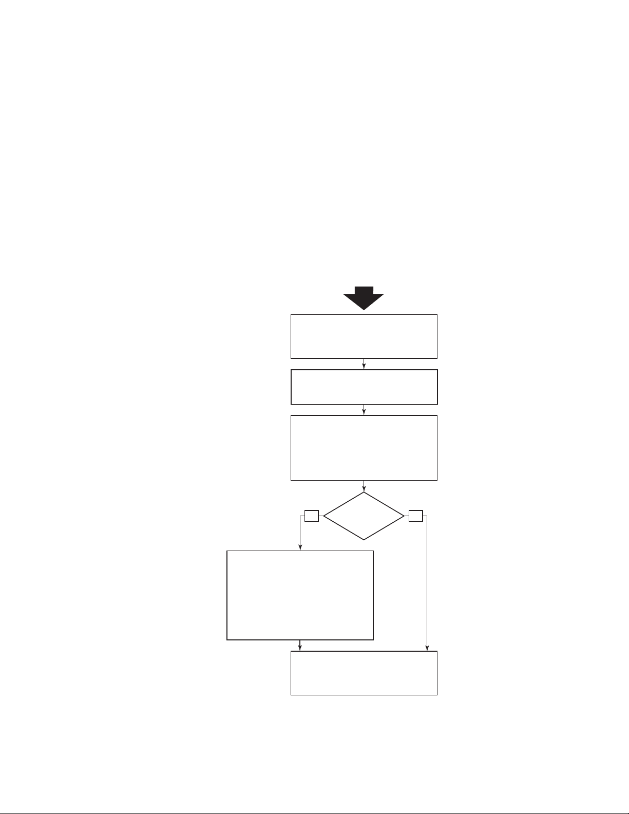
• Appendix A, “Adapter Configuration,” is optional for expert network administrators, who need to
· Install adapter drivers, utilities, and other
software in host system.
· Verify software and hardware installation.
· Configure HCM agent operation as necessary.
· Configure network addressing (CNA only).
Chapter 3
Appendix A
· Configure boot over SAN on BIOS- or UEFI-
based systems.
· Install operating system, adapter drivers,
utilities, and other software on boot devices.
· Configure fabric-based boot LUN discovery
if needed.
· Boot host systems without operating systems
or remote drives if needed.
Chapter 4
Chapter 2
Booting from
external
boot device?
Install adapter hardware in host system,
connect to switch, and verify installation.
NoYe s
Optional instructions for expert users.
Configure instance-specific and driver-level
parameters to control adapter operation.
Chapter 1
Determine host system compatibility,
required hardware, and required
software packages for installation.
Start
modify values for adapter instance-specific persistent and driver-level configuration
parameters.
• Appendix B, “List of Acronyms,” provides a list of acronyms used in this publication and their
definitions.
• Appendix C, “MIB Reference,” provides information on the MIB groups and objects that support
the Simple Network Management Protocol (SNMP) for CNA adapters and Fabric Adapter ports
configured in CNA mode.
How to use this document for installing adapters
Figure 1 illustrates a flowchart of how to use chapters in this manual to install and configure
adapters.
FIGURE 1 Installing adapters using this document
xii Brocade Adapters Installation and Reference Manual
53-1002144-01
Page 13

Supported adapter hardware and software
NOTE
This section provides an overview of Brocade adapter supported hardware and software.
Fabric Adapters
Brocade Fabric Adapter ports can be configured for CNA, NIC, or HBA operation using Brocade
Command Utility (BCU) commands. Ports configured in CNA or NIC mode require appropriate
10GbE SFPs or direct-attached SFP+ with copper cables and operate at a 10 Gbps maximum rate.
Those configured in HBA mode require appropriate 8 or 16 Gbps Fibre Channel SFPs and operate
at an 8 or 16 Gbps maximum rate depending on the installed small form factor pluggable
transceiver (SFP+).
The Brocade 1860 is a single or dual-port stand-up adapter that ships in the following
configurations.
• Single-port model - 16 Gbps Fibre Channel SFP, 10GbE SFP, or no optics.
• Dual-port model - Two 16 Gbps Fibre Channel, two 10GbE SFPs, or no optics).
Note that although adapters may ship with specific optics (or no optics) installed, you can replace
with compatible optics, such as 8 Gbps FC SFPs, long-wave SFPs, and SFP+ direct-attach copper
cables. Refer to “Hardware compatibility” on page 4 for more information.
CNAs
The following Fibre Channel over Ethernet (FCoE) CNAs are supported:
• Brocade 1007. Dual-port mezzanine CNA with a per-port maximum of 10 Gbps. This is an IBM
compact form factor horizontal (CFFh) mezzanine-type adapter that installs on supported
server blades.
• Brocade 1010. Single-port stand-up CNA with a per-port maximum of 10 Gbps.
• Brocade 1020. Dual-port stand-up CNA with a per-port maximum of 10 Gbps.
• Brocade 1741. Dual-port mezzanine card CNA with a per-port maximum of 10 Gbps. This is a
small-form-factor (SFF) mezzanine card that mounts in a Dell blade server.
Install only Brocade-branded small form factor pluggables (SFPs) in stand-up CNAs. Mezzanine CNAs
do not have SFPs and external port connectors, but utilize internal ports and connections to switch
and I/O modules installed in the blade system enclosure.
HBAs
The following Fibre Channel host bus adapters (HBAs) are supported:
• Brocade 415. Single-port stand-up HBA with a per-port maximum of 4 Gbps using a 4 Gbps
SFP.
• Brocade 425. Dual-port stand-up HBA with a per-port maximum of 4 Gbps using a 4 Gbps SFP.
• Brocade 804. Dual-port mezzanine HBA with a per-port maximum of 8 Gbps. This HBA installs
on Hewlett Packard blade servers that install in supported blade system enclosures.
Brocade Adapters Installation and Reference Manual xiii
53-1002144-01
Page 14

• Brocade 815. Single-port stand-up HBA with a per-port maximum of 8 Gbps using an 8 Gbps
NOTE
SFP+.
• Brocade 825. Dual-port stand-up HBA with a per-port maximum of 8 Gbps using an 8 Gbps
SFP+.
Install only Brocade-branded small form factor pluggables (SFPs) in stand-up HBAs. Mezzanine
HBAs do not have SFPs and external port connectors, but utilize internal ports and connections to
switch and I/O modules installed in the blade system enclosure.
Note the following about HBA support
• This publication only supports the HBA models listed under “HBAs” on page xiv and does not
provide information about the Brocade 410 and 420 Fibre Channel HBAs, also known as the
Brocade 400 Fibre Channel HBAs.
• Although you can install an 8 Gbps SFP+ into a Brocade 415 or 425 HBA, only 4 Gbps
maximum port speed is possible.
Fabric OS and switch support
Brocade adapters support Brocade Fabric OS and switches.
Fabric Adapters
Support for Fabric Adapter ports depend on the following mode (CNA, HBA, or NIC) in which they
are configured:
• Ports on Fabric Adapters configured in CNA mode can connect to Fibre Channel SANs and
Ethernet data networks through a compatible FCoE switch. These ports can also connect to
standard Ethernet LAN switch. For a current list of compatible switches, refer to the latest
interoperability matrices on the adapters website at
www.brocade.com/adapters.
• Ports configured in HBA mode support Fabric OS and connect to SANs through fabric switches
or connect directly to Fibre Channel storage arrays. For a current list of compatible switches,
refer to the latest interoperability matrices on the adapters website at
www.brocade.com/adapters.
• Ports configured in NIC mode fully support the Ethernet protocol and connect directly to the
Ethernet LAN.
CNAs
Brocade CNAs must connect to Fibre Channel SANs and Ethernet data networks through a
compatible FCoE switch. For a current list of compatible switches, refer to the latest interoperability
matrices on the adapters website at
www.brocade.com/adapters.
HBAs
Brocade HBAs connect to Fibre Channel SANs through compatible fabric switches or connect
directly to Fibre Channel storage arrays. For a current list of compatible switches, refer to the latest
interoperability matrices on the adapters website at www.brocade.com/adapters.
xiv Brocade Adapters Installation and Reference Manual
53-1002144-01
Page 15

Host operating system support
NOTE
NOTE
Refer to “Host operating system support for adapter drivers” on page xv for information on
operating systems that support the Brocade Host Connectivity Manager (HCM), Brocade Command
Line Utility (BCU), and adapter drivers.
Host operating system support for adapter drivers
This section lists operating system support for all models of the following types of Brocade
adapters:
• Fabric Adapters - Refer to the following subsections depending on your port mode and SFP
configurations:
- “FCoE support” on page xvi and “Ethernet support” on page xvi for ports configured in CNA
mode.
- “Fibre Channel support” on page xv, for ports configured in HBA mode.
- “Ethernet support” on page xvi for ports configured in NIC mode.
• CNAs- Refer to the following subsections:
- “FCoE support” on page xvi
- “Ethernet support” on page xvi.
• HBAs - Refer to “Fibre Channel support” on page xv.
Specific operating system release levels, service pack levels, and other patch requirements are
detailed in the current adapter release notes.
Also refer to the latest Brocade interoperability matrices on the Brocade website at
www.brocade.com/adapters for a list of supported host systems and operating systems.
Fibre Channel support
The following lists operating systems that support Fibre Channel operation for HBAs and for Fabric
Adapter ports configured in HBA mode:
• Windows 2003 R2/SP2 (x86 and x64)
• Windows Server 2008 (Longhorn) (x86 and x64)
• Windows Server 2008 R2/SP1 (x64)
• Microsoft Hyper V for Windows 2008 x86, x64
• Windows 7 (x86 and x64)
• Windows Server Core for Windows 2008 (x86 and x64)
• Microsoft WinPE 3.0 for Windows 2008 (x86 and x64)
• Linux RHEL4.9, 5.5, 5.6, 6.0, 6.1
• Linux SLES 10 and 11 (x86 and x64)
Brocade Adapters Installation and Reference Manual xv
53-1002144-01
Page 16

• Solaris 10 (x86, x64, and SPARC)
NOTE
NOTE
NOTE
NOTE
Solaris is not supported on Brocade 804 or 1007 adapters.
• VMware ESX Server 4.0, 4.1, 5.0 (x64)
Drivers and BCU are supported on the VMware ESX platforms. HCM is supported only on the
guest system on VMware.
• Oracle Enterprise Linux (OEL) 5.6, 6.0 (x86 and x64), Oracle VM 3.0
FCoE support
The following lists operating systems that support FCoE operation for Brocade CNAs and Fabric
Adaptor ports configured in CNA mode:
• Windows Server 2008 (x86 and x64)
• Windows Server 2008 R2/SP1 (x64)
• Microsoft Hyper V for Windows 2008 x86, x64
• Windows 7 (x86 and x64)
• Windows Server Core for Windows 2008 (x86 and x64)
• Microsoft WinPE 3.0 for Windows 2008 (x86 and x64)
• Linux RHEL 4.9, 5.5, 5.6, 6.0, 6.1 (x86 and x64)
• Linux SLES 10 and 11 (x86 and x64)
• Solaris 10 (x86, x64, and SPARC)
Solaris is not supported on Brocade 804 or 1007 adapters.
• VMware ESX Server 4.0, 4.1, 5.0 (x64)
Drivers and BCU are supported on the VMware ESX platforms. HCM is supported only on the
guest system on VMware.
• Oracle Enterprise Linux (OEL) 5.6, 6.0 (x86 and x64)0
Ethernet support
The following lists operating systems that support Ethernet operation for Brocade CNAs and Fabric
Adaptor ports configured in CNA or NIC modes:
• Windows Server 2008 (x86 and x64)
• Windows 2008 R2/SP1 (x64)
• Windows Server Core for Windows 2008 (x86 and x64)
• Windows 7 (x86 and x64)
• Microsoft WinPE 3.0 for Windows 2008 (x86 and x64)
xvi Brocade Adapters Installation and Reference Manual
53-1002144-01
Page 17

• Linux RHEL 4.9, 5.5, 5.6, 6.0, 6.1 (x86 and x64)
NOTE
NOTE
NOTE
• Linux SLES 10 and 11 (x86 and x64)
• Solaris 10 (x86, x64, and SPARC)
Solaris is not supported on Brocade 804 or 1007 adapters.
• Xen Hypervisor (x86 and x64)
Refer to “Hypervisor support” on page xvii.
• VMware ESX Server 4.0, 4.1, and 5.0 (x64)
Drivers and BCU are supported on the VMware ESX platforms. HCM is supported only on the
guest system on VMware. Network drivers are not supported on IA-64 systems.
• Oracle Enterprise Linux (OEL) 5.6, 6.0 (x86 and x64)
Hypervisor support
The following lists operating systems that support hypervisor operation for Brocade adapters:
• Windows Server 2008 Hyper-V (x64)
• Linux RHEVH 6.x (x64)
• Linux XEN (x86 and x64)
• Linux KVM (x64)
• VMware ESX 4.0, 4.1, and 5.0 (x64)
• Oracle VM 3.0 (x64)
• Citrix XenServer 6.0 (x64)
Host operating system support for HCM
The following operating systems support HCM management for adapters.
• Windows Server 2008 (x86 and x64)
• Windows Server 2008 R2/SP1 (x86 and x64)
• Windows SBS 2011 (x64)
• Windows XP
• Windows Vista
• Windows 7 SP1 (x86 and x64)
• Linux 5.5, 5.6, 6.0, 6.1 (x86 and x64)
HCM is a 32-bit application. To use HCM on Linux RHEL 6.0 x64 systems, you must install the
x32-compatible libraries because they are not installed by default.
• Linux SLES 10 and 11 (x86 and x64)
Brocade Adapters Installation and Reference Manual xvii
53-1002144-01
Page 18

• Solaris 11, except Open Solaris (x86, x64, and SPARC)
NOTE
NOTE
NOTE
• VMware ESX Server 4.0, 4.1, 5.0 (x64)
HCM is not supported in ESXi systems.
HCM is supported only on the guest operating system for VMware.
• Oracle Enterprise Linux (OEL) 5.6, 6.0 (x86 and x64)
Specific operating system service patch levels and other patch requirements are detailed in the
current release notes for your adapter software version.
What’s new in this document
This document adds details on adapter software release 3.0 and the Brocade 1860 Fabric Adapter.
For further information about new features not covered in this document and documentation
updates, refer to the release notes for your adapter software version.
Document conventions
This section describes text formatting conventions and important notice formats used in this
document.
Text formatting
The narrative-text formatting conventions that are used are as follows:
bold text Identifies command names
italic text Provides emphasis
code text Identifies CLI output
For readability, command names in the narrative portions of this guide are presented in mixed
lettercase: for example, switchShow. In actual examples, command lettercase is often all
lowercase.
Identifies the names of user-manipulated GUI elements
Identifies keywords and operands
Identifies text to enter at the GUI or CLI
Identifies variables
Identifies paths and Internet addresses
Identifies document titles
Identifies command syntax examples
xviii Brocade Adapters Installation and Reference Manual
53-1002144-01
Page 19

Command syntax conventions
NOTE
ATTENTION
CAUTION
DANGER
Command syntax in this manual follows these conventions:
command Commands are printed in bold.
--option, option Command options are printed in bold.
-argument, arg Arguments.
[ ] Optional element.
variable Variables are printed in italics. In the help pages, values are underlined
enclosed in angled brackets < >.
... Repeat the previous element, for example “member[;member...]”
value Fixed values following arguments are printed in plain font. For example,
--show WWN
| Boolean. Elements are exclusive. Example:
--show -mode egress | ingress
or
Command examples
This book describes how to perform configuration tasks using the Fabric OS command line
interface and the BCU interface, but does not describe the commands in detail. For complete
descriptions of all commands, including syntax, operand description, and sample output, see the
Brocade Fabric OS Command Reference Manual and Brocade Adapters Administrator’s Guide.
Notes, cautions, and warnings
The following notices and statements are used in this manual. They are listed below in order of
increasing severity of potential hazards.
A note provides a tip, guidance, or advice, emphasizes important information, or provides a
reference to related information.
An Attention statement indicates potential damage to hardware or data.
A Caution statement alerts you to situations that can be potentially hazardous to you or cause
damage to hardware, firmware, software, or data.
A Danger statement indicates conditions or situations that can be potentially lethal or extremely
hazardous to you. Safety labels are also attached directly to products to warn of these conditions
or situations.
Brocade Adapters Installation and Reference Manual xix
53-1002144-01
Page 20

Key terms
For definitions specific to Brocade and Fibre Channel, see the technical glossaries by logging into
http://my.brocade.com.
For definitions specific to this document, see Appendix C, “List of Acronyms”.
For definitions of SAN-specific terms, visit the Storage Networking Industry Association online
dictionary at:
http://www.snia.org/education/dictionary
Notice to the reader
This document may contain references to the trademarks of the following corporations. These
trademarks are the properties of their respective companies and corporations.
These references are made for informational purposes only.
Corporation Referenced Trademarks and Products
Microsoft Corporation Windows, Windows Server 2003, Windows Server 2008, Vista,
Oracle Corporation Solaris
Red Hat Inc. Red Hat Enterprise Linux (RHEL)
Novell, Inc. SUSE Linux Enterprise Server (SLES)
VMware Inc. ESX Server
SPARC International, Inc. SPARC
Hewlett Packard Corp. BladeSystem
IBM BladeCenter
Dell PowerEdge
XP, PE for Windows, Hyper V for Windows, Windows Automated
Installation Kit (WAIK), and Windows 7
Additional information
This section lists additional Brocade and industry-specific documentation that you might find
helpful.
Brocade resources
To get up-to-the-minute information, go to http://my.brocade.com to register at no cost for a user ID
and password. A variety of resources for Brocade products is available.
xx Brocade Adapters Installation and Reference Manual
53-1002144-01
Page 21

Adapters
For adapter resources, such as product information, software, firmware, and documentation, visit
the adapters website www.brocade.com/adapters.
For additional information on Brocade adapters, refer to the following publications:
• The Brocade Quick Installation Guide (provided with your adapter model).
• Brocade Adapters Troubleshooting Guide
• Brocade Adapters Administrator’s Guide
• CIM Provider for Brocade Adapters Installation Guide
FCoE Switch
For information on the Brocade FCoE Switch for connecting stand-up CNAs and Fabric Adapter
ports configured in CNA mode, refer to the following publications:
• Brocade 8000 Hardware Reference Manual
• WebTools Administrator’s Guide
• EZSwitchSetup Administrator’s Guide
• Fabric OS Command Reference Manual
Blade servers and blade system enclosure components
The Brocade mezzanine card adapters are compatible with blade servers, switch modules,
interconnect modules, I/O modules, and other components that install in supported blade system
enclosures. For compatibility information, visit the compatible blade server and blade system
enclosure manufacturer’s website. Also refer to “Hardware compatibility” on page 10.
SAN information
White papers, online demonstrations, and data sheets are available through the Brocade website
at:
http://www.brocade.com/products-solutions/products/index.page
For additional Brocade documentation, visit the Brocade website:
http://www.brocade.com
Other industry resources
For additional resource information, visit the Technical Committee T11 website. This website
provides interface standards for high-performance and mass storage applications for Fibre
Channel, storage management, and other applications:
http://www.t11.org
For information about the Fibre Channel industry, visit the Fibre Channel Industry Association
website:
http://www.fibrechannel.org
Brocade Adapters Installation and Reference Manual xxi
53-1002144-01
Page 22

Providing details for support
Contact your Brocade adapter support supplier for hardware, firmware, and software support,
including product repairs and part ordering. Provide the following information:
1. General information:
• Brocade adapter model number.
• Host operating system version.
• Software name and software version, if applicable.
• syslog message logs
• Support Save output
To expedite your support call, use the Support Save feature to collect debug information
from the driver, internal libraries, and firmware. You can save valuable information to your
local file system and send it to support personnel for further investigation. For details on
using this feature, refer to “Support Save overview” on page xxiv.
• Detailed description of the problem, including the switch or fabric behavior immediately
following the problem, and specific questions.
• Description of any troubleshooting steps already performed and the results.
2. Adapter serial number:
The adapter serial number and corresponding bar code are provided on the serial number
label illustrated below. This label is located on the adapter card.
*FT00X0054E9*
FT00X0054E9
You can also display the serial number through the following HCM dialog boxes and BCU
commands:
• Adapter Properties tab in HCM.
Select an adapter in the device tree, then click the Properties tab in the right pane.
• BCU adapter --list command.
This command lists all Brocade adapters in the system and information such as model and
serial numbers.
3. Port World-Wide Name (PWWN).
Determine the PWWN through the following resources:
• Label on the adapter card contains the PWWN for each port.
• Brocade BIOS Configuration Utility.
Select the appropriate adapter port from the initial configuration utility screen, then select
Adapter Settings to display the WNN and PWWN for the port. For details, refer to
“Configuring BIOS using the Brocade configuration utility” on page 136.
• Port Properties tab in HCM.
Select a port for a specific adapter in the device tree, then click the Properties tab in the
right pane.
xxii Brocade Adapters Installation and Reference Manual
53-1002144-01
Page 23

• The following BCU commands:
NOTE
Command Function
port ---query port_id Displays port information, including the PWWN
for the FCoE port. The <port_id> parameter is
the port number.
port ---list Lists all the physical ports on the adapter along
with their basic attributes, such as the PWWN.
4. Media access control (MAC) addresses. These are applicable to CNAs and Fabric Adapter ports
configured in CNA mode only.
The MAC address can be found in HCM by selecting the adapter in the device tree and clicking
the Properties tab in the right pane to display the adapter Properties panel. Look for the MAC
Address field.
Each port has a “burned-in” local port MAC address. This is the source MAC for LLDP
communications between the adapter and FCoE switch. To find this MAC address, select a DCB
port in the HCM device tree, then click the Properties tab in the right pane to display the port
Properties panel. Look for the Local port MAC field.
The Ethernet MAC address is used for normal Ethernet operations. To find this MAC address
using HCM, select an Ethernet port in the HCM device tree, then click the Properties tab in the
right pane to display the port Properties panel. Look for the Current MAC address and Factory
MAC address fields.
Each enode logging in to the fabric through a local adapter port is assigned a MAC address
during FCoE Initialization Protocol (FIP) operations. This MAC is assigned for the current FCoE
communication only. To find this MAC address, perform one of the following tasks:
• Select an FCoE port in the HCM device tree, then click the Properties tab in the right
pane to display the port Properties panel. Look for the FCoE MAC field.
• Enter the port --query port_id BCU command. Look for the FCoE MAC.
MAC addresses assigned during FCoE initialization operations cannot be changed using device
management applications.
The FCoE Forwarder (FCF) MAC address is the address of the attached FCoE switch. Select an
FCoE port in the HCM device tree, then click the Properties tab in the right pane to display the
port Properties panel. Look for the FCF MAC field.
You can also determine port MAC addresses using the following BCU commands:
Command Function
port --query port_id Displays port information, including the MAC
addresses. The <port_id> parameter is the
port number.
port --list Lists all the physical ports on the CNA along
with the adapter, Ethernet, and FCoE MAC
addresses.
Brocade Adapters Installation and Reference Manual xxiii
53-1002144-01
Page 24

NOTE
For details on using HCM and BCU commands, refer to the Brocade Adapters
NOTE
Administrator’s Guide.
Support Save overview
The Support Save feature is an important tool for collecting debug information from the driver,
internal libraries, and firmware. You can save this information to the local file system and send it to
support personnel for further investigation. Use one of the following options to launch this feature:
• In HCM, launch Support Save through the Tools menu.
• In Management applications, use the Technical SupportSave dialog box.
• For BCU, enter the bfa_supportsave command.
For VMware ESX 5.0 and later systems, BCU commands are integrated with the esxcli
infrastructure. To initiate the BCU supportsave command, enter esxcli brocade supportsave on
the ESX system.
• Through your internet browser (Internet Explorer 6 or later or Firefox 2.0 or later), you can
collect Support Save output if you do not have root access, do not have access to file transfer
methods such as File Transfer Protocol (FTP) and Secure Copy (SCP), or do not have access to
the Host Connectivity Manager (HCM).
• A Support Save collection can also occur automatically for a port crash event.
Launching Support Save through BCU, HCM, and during a port crash event saves the following
information:
• Adapter model and serial number
• Adapter firmware version
• Host model and hardware revision
• All support information
• Adapter configuration data
• All operating system and adapter information needed to diagnose field issues
• Information about all adapters in the system
• Firmware and driver traces
• Syslog message logs
• Windows System Event log .evt file
• HCM GUI-related engineering logs
• Events
• Adapter configuration data
• Environment information
• Data .xml file
• Vital CPU, memory, network resources
• HCM Agent (logs, configuration)
• Driver logs
xxiv Brocade Adapters Installation and Reference Manual
53-1002144-01
Page 25

• Install logs
NOTE
NOTE
• Core files
• Details on the CNA or Fabric Adapter Ethernet interface, including IP address and mask.
• Status and states of all adapter ports, including the Ethernet, FCoE, and DCB ports on CNAs
and Fabric Adapters.
• DCB status and statistics for CNAs and Fabric Adapters
• Network driver information, Ethernet statistics, offload parameters, and flow control coalesce
parameters for CNAs and Fabric Adapters.
• Ethernet offload and flow control parameters for CNAs and Fabric Adapters.
Before collecting data through the Support Save feature, you may want to disable auto-recovery on
the host system. When adapters are reset after an auto-recovery from a failure, traces initiated
before the failure may be lost or overwritten.
To disable auto-recovery, use the following commands:
• For Linux, use the following commands, then reboot the system:
- To disable auto-recovery for the network (BNA) driver.
insmod bna.o bnad_ioc_auto_recover=0
- To disable auto-recovery for the storage (BFA) driver.
insmod bfa.o ioc_auto_recover=0
• For VMware, use the following commands.
- To unload and load the network (BNA) driver with IOC auto-recovery disabled, use the
following commands:
esxcfg-module -u bna
esxcfg-module bna bnad_ioc_auto_recover=0
- To disable IOC auto-recovery for the network (BNA) driver across reboots, use the following
command:
esxcfg-module -s "bnad_ioc_auto_recover=0" bna
- To disable IOC auto-recovery for the storage (BFA) driver across reboots, use the following
command:
esxcfg-module -s "ioc_auto_recover=0" bfa
• For Windows use the Registry Edit tool (regedt32) or the BCU drvconf --key command.
Following is the drvconf ---key command:
bcu drvconf --key ioc_auto_recover --val 0
• For Solaris, edit /kernel/drv/bfa.conf using the following command:
ioc-auto-recover=0
Brocade 804 and 1007 adapters are not supported on Solaris systems.
Brocade Adapters Installation and Reference Manual xxv
53-1002144-01
Page 26

Initiating Support Save through HCM
NOTE
Launching the Support Save feature in HCM collects HCM application data. Launch Support Save
by selecting Tools > Support Save.
Messages display during the Support Save operation that provide the location of the directory
where data is saved. If you are initiating Support Save from a remote management station and
receive a warning message that support files and Agent logs could not be collected, the HCM Agent
is unavailable on the remote host. Select Too ls > Backup to back up data and configuration files
manually.
For more information and additional options for using this feature, refer to the Brocade Adapters
Administrator’s Guide.
Initiating Support Save through BCU commands
Use the bfa_supportsave command to Initiate Support Save through the BCU:
• bfa_supportsave -
- Creates and saves the supportsave output under the /tmp directory on Linux and Solaris
systems.
- Creates and saves the supportsave output under the current directory for Windows
systems.
• bfa_supportsave <dir> - Creates and saves the supportsave output under a directory name
that you provide.
• bfa_supportsave <dir> <ss_file_name> - Creates and saves the supportsave output under a
directory and file name that you provide. If the directory already exists, it will be overwritten.
If specifying a directory, make sure that the directory does not already exist to prevent overwriting
the directory. Do not just specify a drive (such as C:) or C:\Program Files.
Messages display as the system gathers information. When complete, an output file and directory
display. The directory name specifies the date when the file was saved.
For more information on the bfa_supportsave command, refer to the Host Connectivity Manager
(HCM) Administrator’s Guide.
VMware ESX systems
For VMware ESX 5.0 and later systems, BCU commands are integrated with the esxcli
infrastructure. To initiate the BCU supportsave command, enter esxcli brocade supportsave to
initiate Support Save:
Initiating Support Save through the internet browser
Initiate bfa_supportsave through an internet browser.
1. Open an internet browser and type the following URL:
https://localhost:34568/JSONRPCServiceApp/SupportSaveController.do
xxvi Brocade Adapters Installation and Reference Manual
53-1002144-01
Page 27

In this URL, localhost is the IP address of the server from which you want to collect the
NOTE
bfa_supportsave information.
2. Log in using the factory default user name (admin) and password (password). Use the current
user name and password if they have changed from the default.
The File Download dialog box displays, prompting you to save the
file.
3. Click Save and navigate to the location where you want to save the file.
4. Save the file, but rename it with a “zip” extension. For example:
supportSaveController.zip.
5. Open the file and extract contents using any compression utility program.
SupportSaveController.do
Initiating Support Save through a port crash event
If the port crashes and triggers a port crash event, Support Save data is collected at a system-wide
level. An Application Log message is generated with the following message:
Port Crash Support Save Completed
Port crash events have a CRITICAL severity and you can view the details in the Master Log and
Application Log tables in HCM.
Support Save differences
Following are differences in data collection for the HCM, BCU, and browser applications of
bfa_supportsave:
• BCU - Collects driver-related logs, HCM Agent information, and configuration files.
• Browser - Collects driver-related and HCM Agent logs and configuration files.
• HCM - Collects HCM application data, driver information, HCM Agent logs, and configuration
files.
Master and Application logs are saved when Support Save is initiated through HCM, but not through
BCU.
Document feedback
Quality is our first concern at Brocade and we have made every effort to ensure the accuracy and
completeness of this document. However, if you find an error or an omission, or you think that a
topic needs further development, we want to hear from you. Forward your feedback to:
documentation@brocade.com
Provide the title and version number of the document and as much detail as possible about your
comment, including the topic heading and page number and your suggestions for improvement.
Brocade Adapters Installation and Reference Manual xxvii
53-1002144-01
Page 28

xxviii Brocade Adapters Installation and Reference Manual
53-1002144-01
Page 29

Chapter
Product Overview
In this chapter
•Fabric Adapters . . . . . . . . . . . . . . . . . . . . . . . . . . . . . . . . . . . . . . . . . . . . . . . . . 1
•Converged network adapters . . . . . . . . . . . . . . . . . . . . . . . . . . . . . . . . . . . . . . 5
•Host bus adapters . . . . . . . . . . . . . . . . . . . . . . . . . . . . . . . . . . . . . . . . . . . . . . 12
•Adapter features . . . . . . . . . . . . . . . . . . . . . . . . . . . . . . . . . . . . . . . . . . . . . . . 16
•Adapter management features. . . . . . . . . . . . . . . . . . . . . . . . . . . . . . . . . . . . 31
•Adapter software . . . . . . . . . . . . . . . . . . . . . . . . . . . . . . . . . . . . . . . . . . . . . . . 37
•Items shipped with your adapter . . . . . . . . . . . . . . . . . . . . . . . . . . . . . . . . . . 48
•Boot installation packages . . . . . . . . . . . . . . . . . . . . . . . . . . . . . . . . . . . . . . . 49
•Downloading software and publications . . . . . . . . . . . . . . . . . . . . . . . . . . . . 52
•Using BCU commands. . . . . . . . . . . . . . . . . . . . . . . . . . . . . . . . . . . . . . . . . . . 53
1
Fabric Adapters
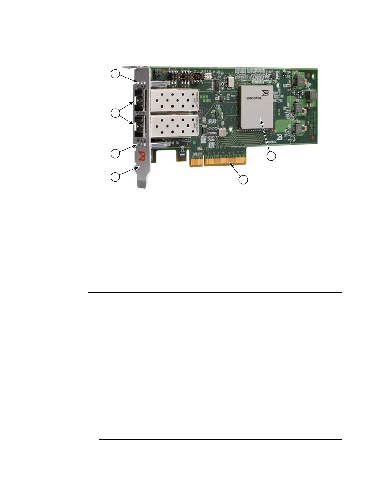
The Brocade 1860 stand-up Fabric Adapter is a low-profile MD2 form factor PCI Express (PCIe) card
that installs in standard host computer systems. Figure 2 illustrates major components of the
dual-port Brocade 1860 Fabric Adapter. Brocade 1860 single or dual-port adapter models can ship
with the following configurations of small form factor pluggable (SFP) transceivers:
• Single-port model - 16 Gbps Fibre Channel SFP+, 10GbE SFP+, or without optics.
• Dual-port model - Two 16 Gbps Fibre Channel SFP+, two 10GbE SFP+, or without optics.
Although adapters may ship with specific optics (or no optics) installed, you can replace with
compatible optics, such as 8 Gbps FC SFPs, long-wave SFPs, and SFP+ direct-attach copper cables.
Refer to “Hardware compatibility” on page 4 for more information.
Please note that the following illustration is representative and may have minor physical
differences from the card that you purchased.
Brocade Adapters Installation and Reference Manual 1
53-1002144-01
Page 30
Fabric Adapters
ATTENTION
NOTE
2
3
1
4
5
6
1
FIGURE 2 Brocade 1860 Fabric Adapter (heat sink removed)
1LEDs for port 1 SFP
2 Cable connectors for port 1 and port 0 SFPs (Fiber optic SFP illustrated)
3LEDs for port 0 SFP
4 Low-profile mounting bracket.
Note: The adapter ships with the standard (full-height) mounting bracket
installed.
5 PCIe x8 connector
6ASIC
Only use Brocade-branded SFP+ laser transceivers supplied with stand-up Fabric Adapters.
AnyIO technology
Although the Brocade 1860 can be shipped in a variety of SFP configurations, you can change port
function to the following modes using the Brocade AnyIO technology, provided the correct SFP is
installed for the port:
• HBA or Fibre Channel mode. This mode utilizes the Brocade Fibre Channel storage driver. An 8
or 16 Gbps Fibre Channel SFP can be installed for the port. The port provides Host Bus Adapter
(HBA) functions on a single port so that you can connect your host system to devices on the
Fibre Channel SAN. Ports with 8 Gbps SFPs configured in HBA mode can operate at 2, 4, or 8
Gbps. Ports with 16 Gbps SFPs configured in HBA mode can operate at 4, 8, or 16 Gbps.
Fabric Adapter ports set in HBA mode appear as “FC” ports when discovered in HCM. They
appear as “FC HBA” to the operating system.
Fibre Channel mode and HBA mode may be used interchangeably in this document.
2 Brocade Adapters Installation and Reference Manual
53-1002144-01
Page 31

Fabric Adapters
NOTE
NOTE
1
• Ethernet or NIC mode. This mode utilizes the Brocade network driver. A 10 GbE SFP or direct
attached SFP+ copper cable must be installed for the port. This mode supports basic Ethernet,
Data Center Bridging (DCB), and other protocols that operate over DCB to provide functions on
a single port that are traditionally provided by an Ethernet Network Interface Card (NIC). Ports
configured in this mode can operate up to 10 Gbps. Fabric Adapters that ship from the factory
with 10GbE SFPs installed or no SFPs installed are configured for Ethernet mode by default.
Fabric Adapter ports set in NIC mode appear as Ethernet ports when discovered in HCM. These
ports appear as “10 GbE NIC” to the operating system.
Ethernet and NIC mode may be used interchangeably in this document.
• CNA mode. This mode provides all functions of Ethernet or NIC mode, plus adds support for
FCoE features by utilizing the Brocade FCoE storage driver. A 10 GbE SFP or direct attached
SFP+ copper cable must be installed for the port. Ports configured in CNA mode connect to an
FCoE switch. These ports provide all traditional CNA functions for allowing Fibre Channel traffic
to converge onto 10 Gbps DCB networks. The ports even appear as network interface
controllers (NICs) and Fibre Channel adapters to the host. FCoE and 10 Gbps DBS operations
run simultaneously.
Fabric Adapter ports set CNA mode appear as FCoE ports when discovered in HCM. These
ports appear as “10 GbE NIC” to the operating system.
Changing the port mode
You can change the mode of individual ports on an adapter using the following BCU commands:
• The bcu port --mode command allows you can change the mode of individual ports on the
adapter.
• The bcu adapter --mode command allows you can change all ports on the adapter to a specific
mode.
For more information on these commands, refer to the Brocade Adapters Administrator’s Guide.
As general steps to change a port’s operating mode, perform the following steps:
1. Change the mode using the bcu port --mode or bcu adapter --mode BCU commands.
2. Make sure the appropriate SFP (FC or 10 GbE) and driver packages are installed to operate the
port in the selected mode if they are not already installed. Refer to Table 9 on page 44 for
information on drivers.
3. Power-cycle the host system.
Dynamically changing the port mode is equivalent to plugging in a new device in the system. so
the system must be power-cycled for this configuration change to take effect.
For Windows systems you must install the drivers for the new mode after the system is rebooted.
This is not required if the appropriate driver is already pre-installed in the system.
When you change the port mode, the port resets to factory defaults for physical functions (PF)
associated with the mode (refer to “Factory default PF configurations” on page 16). For details on
configuring ports for different operating modes, refer to the Brocade Adapters Administrator’s
Guide.
Brocade Adapters Installation and Reference Manual 3
53-1002144-01
Page 32

Fabric Adapters
1
Hardware compatibility
This section outlines important compatibility information.
SFP transceivers
Use only the Brocade-branded small form factor pluggable (SFP) transceivers described in this
section for stand-up Brocade Fabric Adapters.
Ports configured in CNA or NIC mode
Tab le 1 provides the type, description, and switch compatibility information for supported SFPs that
can be installed in ports configured in CNA or NIC mode.
TABLE 1 Compatible SFPs for ports configured in CNA or NIC mode
Type Description Switch Compatibility
10 Gb ps SR (sh ort ran ge)
SFP+, 1490 NM
10 Gbps LR (long range)
SFP+, 10 km. 1310 NM
1 meter direct-attached
SFP+ copper cable
3 meter direct-attached
SFP+ copper cable
5 meter direct-attached
SFP+ copper cable
Optical short range SFP+ for
Distance depends on cable
type. Refer to “Cabling” on
page 176.
Optical long range SFP+ for
fiber optic cable 10 km (6.2
mi.)
SFP+ for 1-meter (3.2 feet)
maximum twinaxial copper
cable
SFP+ for 3-meter maximum
twinaxial copper cable (9.8
feet)
SFP+ for 5-meter maximum
twinaxial copper cable (16.4
feet)
Any switch compatible with
the adapter
Any switch compatible with
the adapter
Any switch compatible with
the cable.
Any switch compatible with
the cable.
Any switch compatible with
the cable.
Ports configured in HBA mode
Tab le 2 provides the type, description, and switch compatibility information for supported SFPs that
can be installed in ports configured in HBA mode.
TABLE 2 Compatible SFPs for ports configured in HBA mode
Type Description Switch Compatibility
8 Gbps SWL (short wave
laser) SFP+
8 Gbps LWL (long wave
laser) 10 km SFP+
SFP+ for fiber optic cable
Distance depends on cable
type. Refer to “Cabling” on
page 176.
SFP+ for fiber optic cable
Distance depends on cable
type. Refer to “Cabling” on
page 176.
Any switch compatible with
the adapter
Any switch compatible with
the adapter
4 Brocade Adapters Installation and Reference Manual
53-1002144-01
Page 33

Converged network adapters
NOTE
TABLE 2 Compatible SFPs for ports configured in HBA mode
Type Description Switch Compatibility
1
16 Gbps SWL (short
wave laser) SFP+
16 Gbps LWL (long wave
laser) 10 km SFP+
SFP+ for fiber optic cable
Distance depends on cable
type. Refer to “Cabling” on
page 176.
SFP+ for fiber optic cable
Distance depends on cable
type. Refer to “Cabling” on
page 176.
Any switch compatible with
the adapter
Any switch compatible with
the adapter
PCI express connections
Brocade Fabric Adapters are compatible with PCI express (PCIe) connections that have the
following specifications:
• x8 lane or greater transfer interface.
• Gen1 (PCI Base Specification 1.0, 1.01a, and 1.1).
• Gen2 (PCI Express Base Specification 2.0).
• Gen 3 (PCI Express Base Specification 3.0)
Install adapters in PCI express connectors with an x8 lane transfer interface or greater for best
performance. You cannot install Fabric Adapters in PCI or PCI-X connectors.
Host systems and switches
For a current list of switches, servers, and applications compatible with Brocade stand-up
adapters, refer to the latest interoperability matrixes on Brocade’s website at
www.brocade.com/adapters.
Storage systems
Using Fabric Adapter ports configured in HBA mode, you can connect a server (host system) to a
Fibre Channel SAN in a switched fabric and point-to-point topology or directly to a storage array in a
point-to-point topology.
Using Fabric Adapter ports configured in CNA mode, you can connect a server (host system) to a
Fibre Channel SAN through connection with a compatible FCoE switch.
Refer to the latest Brocade interoperability matrices for a list of supported server models on
Brocade’s website at
www.brocade.com/adapters.
Converged network adapters
Tab le 3 describes available Brocade FCoE PCIe Converged Network Adapters (CNAs) for PCIe x8
host bus interfaces, hereafter referred to as Brocade CNAs. These adapters provide reliable,
high-performance host connectivity for mission-critical SAN environments. Provided in the table are
the model number, port speed, number of ports, and adapter type for each CNA.
Brocade Adapters Installation and Reference Manual 5
53-1002144-01
Page 34

Converged network adapters
1
TABLE 3 Brocade Fibre Channel CNAs
Model Number Port Speed Number of Ports Adapter Type
1007 10 Gbps maximum 2 Mezzanine
1020 10 Gbps maximum 2 Stand-up
1010 10 Gbps maximum 1 Stand-up
1741 10 Gbps ma x i m um 2 Me z z anine
Two types of CNAs are available:
• Stand-up adapters.
• Mezzanine adapters.
CNA ports connect to an FCoE switch. CNAs combine the functions of a Host Bus Adapter (HBA) and
Network Interface Card (NIC) on one PCIe x8 card. The CNAs even appear as network interface
controllers (NICs) and Fibre Channel adapters to the host. These CNAs fully support FCoE protocols
and allow Fibre Channel traffic to converge onto 10 Gbps Data Center Bridging (DCB) networks.
FCoE and 10 Gbps DCB operations run simultaneously.
These are low-profile MD2 form factor PCI Express (PCIe) cards, measuring 6.6 in. by 2.714 in.
(16.765 cm by 6.89 cm) that install in PCIe connectors in standard host systems.
These are smaller cards that mount on server blades that install in blade system enclosures.
The enclosures contain other system blades, such as switch and pass-through modules.
The combined high performance and proven reliability of a single-ASIC design makes these CNAs
ideal for connecting host systems on Ethernet networks to SAN fabrics based on Brocade Fabric or
M-Enterprise operating systems.
Stand-up adapters
Stand-up type CNAs, such as the 1010 and 1020, are low-profile MD2 form factor PCI Express
(PCIe) cards that install in standard host computer systems. Figure 3 on page 7 illustrates major
components of the Brocade 1020 stand-up CNA with two fiber optic small form factor pluggable
(SFP) transceivers installed. Both stand-up CNAs also support direct-attached SFP+ copper cables.
Please note that the following illustration is representative and may have minor physical
differences from the card that you purchased.
6 Brocade Adapters Installation and Reference Manual
53-1002144-01
Page 35

Converged network adapters
ATTENTION
2
3
1
4
Note: This photo illustrates parts location only. The CNA may not look exactly like your model.
5
6
1
1LEDs for port 1 SFP
2 Cable connectors for port 1 and port 0 SFPs (Fiber optic SFP illustrated)
3LEDs for port 0 SFP
4 Low-profile mounting bracket.
Note: The CNA ships with the low-profile mounting bracket installed.
5 PCIe x8 connector
6ASIC
FIGURE 3 Brocade 1020 stand-up CNA with low-profile mounting bracket (heat sink removed)
Only use Brocade-branded SFP+ laser transceivers supplied with stand-up CNAs.
Brocade Adapters Installation and Reference Manual 7
53-1002144-01
Page 36
Converged network adapters
NOTE
1
Mezzanine adapters
Mezzanine adapters are smaller modules than stand-up models. These mount on server blades
that install in blade system enclosures.
1007
Figure 4 illustrates major components of the Brocade 1007, which is an IBM combo form factor
horizontal (CFFh) CNA containing two ports operating at 10 Gbps. Please note that the following
illustration is representative and may have minor physical differences from the card that you
purchased.
1ASIC with heat sink
2 x8 PCIe interface connector.
3 Release lever. Pull to release adapter from blade server.
4 Holes for guiding card onto blade server system board mounting posts.
5 Holes for guiding card onto blade server system board mounting posts.
6 Midplane connectors
FIGURE 4 Brocade 1007 CNA
Labels showing the part number, PWWNs, port MAC addresses, model number, and serial number
for the Brocade 1007 CNA are on the reverse (top) side of the card.
8 Brocade Adapters Installation and Reference Manual
53-1002144-01
Page 37

Converged network adapters
1
The Brocade 1007 mounts on a server blade that installs in an IBM BladeCenter® enclosure. The
adapter uses FCoE to converge standard data and storage networking data onto a shared Ethernet
link. Ethernet and Fibre Channel communications are routed through the DCB ports on the adapter
to the blade system enclosure midplane, and then onto switch modules installed in the enclosure.
For information on installing the Brocade 1007 CNA on a server blade, refer to Chapter 2,
“Hardware Installation”. For additional information related to the supported blade server, blade
system enclosure, and other devices installed in the enclosure such as I/O modules and switch
modules, refer to the installation instructions provided with these products.
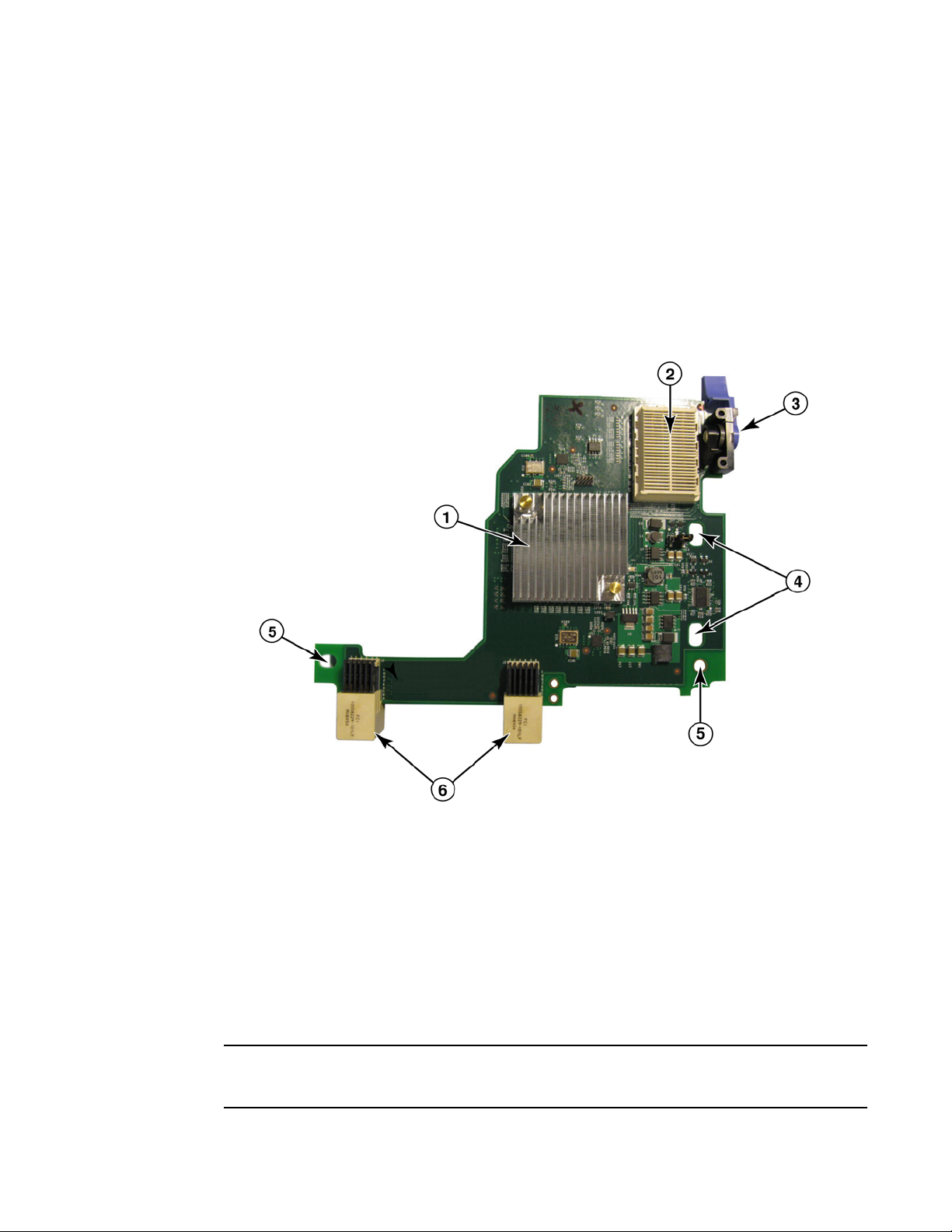
1741
The Brocade® BR1741M-k 2P Mezz Card, also known as the Brocade 1741 mezzanine card, is
small-form factor (SFF) mezzanine card containing two ports operating at 10 Gbps that mounts on a Dell
blade server. Figure 5 illustrates major components of the 1741 adapter. Please note that the following
illustration is representative and may have minor physical differences from the card that you purchased.
1ASIC with heat sink
2 Port WWN and MAC address label
3 OEM PPID and part number label
4Brocade serial number label
FIGURE 5 Brocade 1741 mezzanine card
Brocade Adapters Installation and Reference Manual 9
53-1002144-01
Page 38

Converged network adapters
1
The Brocade 1741 mounts on supported blade servers that install in Dell™ PowerEdge™ M1000e
modular blade systems. It is used in conjunction with matching I/O modules, also installed in the
blade enclosure. The adapter uses FCoE to converge standard data and storage networking data
onto a shared Ethernet link. Ethernet and Fibre Channel communications are routed through the
DCB ports on the adapter to the enclosure backplane then to the I/O module.
For information on installing the Brocade 1741 CNA on a blade server, refer to Chapter 2,
“Hardware Installation”. For additional information related to the supported server blade, blade
enclosure, and other devices installed in the enclosure such as I/O and switch modules, refer to
the installation instructions provided with these products.
Hardware compatibility
This section outlines important compatibility information.
SFP transceivers (stand-up adapters)
Use only the Brocade-branded small form factor pluggable (SFP) transceivers described in Tab le 4
in Brocade stand-up CNAs. The table provides the type, description, and switch compatibility
information for supported SFPs.
TABLE 4 Compatible SFPs for Brocade stand-up CNAs
10 Gb ps SR (sh ort ran ge)
SFP+, 1490 NM
10 Gbps LR (long range)
SFP+, 10 km, 1310 NM
1 meter direct-attached
SFP+ copper cable
3 meter direct-attached
SFP+ copper cable
5 meter direct-attached
SFP+ copper cable
Optical short range SFP+ for
Distance depends on cable
type. Refer to “Cabling
(stand-up adapters)” on
page 183.
Optical long range SFP+ for
fiber optic cable 10 km (6.2
mi.)
SFP+ for 1-meter (3.2 feet)
maximum twinaxial copper
cable
SFP+ for 3-meter maximum
twinaxial copper cable (9.8
feet)
SFP+ for 5-meter maximum
twinaxial copper cable (16.4
feet)
Any switch compatible with
the adapter
Any switch compatible with
the adapter
Any switch compatible with
the cable.
Any switch compatible with
the cable.
Any switch compatible with
the cable.
Host systems and switches (stand-up adapters)
For a current list of switches, servers, and applications compatible with Brocade stand-up
adapters, refer to the latest interoperability matrixes on Brocade’s website at
www.brocade.com/adapters.
10 Brocade Adapters Installation and Reference Manual
53-1002144-01
Page 39

Converged network adapters
NOTE
NOTE
1
Server blades and blade system enclosures (mezzanine adapters)
Consider the following points when installing mezzanine adapters in blade servers and system
enclosures:
• For information on server blades and blade system enclosures that are compatible with
adapters, refer to the “Adapters Resources” section of
• For information about enclosures, server blades, I/O modules, switch modules, and optional
devices that are compatible with this adapter, visit the manufacturer websites for these
products. You can also contact your server blades or blade system enclosure marketing
representative or authorized reseller.
• To support each I/O module that you install in the blade system enclosure, you may also need
to install a compatible adapter in each server blade that you want to communicate with the I/O
module. Also, the adapter may only support switch modules or blades in specific I/O bays of
the enclosure. For additional information, refer to installation and user guides and the
interoperability guides provided for the blade server and blade system enclosure.
• The Brocade mezzanine adapter is compatible with the following types of modules that install
in the supported blade system enclosure:
- Pass-through modules
- I/O modules
- Switch modules
www.brocade.com/adapters.
For detailed information about these modules, see the installation and user guides and
interoperability guides provided for these modules and the blade system enclosure.
• You may be able to install only one mezzanine adapter per server blades. The maximum
number of adapters that you can install in the blade system enclosure varies according to the
type of enclosure that you are using because each type of enclosure may support a different
number of server blades. For additional compatibility information, see the installation, user
guides and interoperability guides provided for the blade server and the blade system
enclosure.
PCI express connections
Brocade CNAs are compatible with PCI express (PCIe) connections that have the following
specifications:
• x8 lane or greater transfer interface.
• Gen1 (PCI Base Specification 1.0, 1.01a, and 1.1).
• Gen2 (PCI Express Base Specification 2.0).
• Gen3 (PCI Express Base Specification 3.0).
Install CNAs in PCI express connectors with an x8 lane transfer interface or greater for best
performance. You cannot install CNAs in PCI or PCI-X connectors.
Brocade Adapters Installation and Reference Manual 11
53-1002144-01
Page 40

Host bus adapters
NOTE
1
Storage systems
Using Brocade CNAs you can connect a server (host system) to a Fibre Channel SAN through
connection with a compatible FCoE switch. For a current list of compatible switches, servers, and
applications, refer to the latest interoperability matrices on Brocade’s website at
www.brocade.com/adapters.
The CNA can connect with a network switch and perform NIC functions for network traffic.
WoL and SoL limitations
The following describes limitations of support for Wake on LAN (WoL) and Serial over LAN (SoL) for
the Brocade 1007 adapter:
• WoL. The adapter does not support WoL over its 10GbE links. WoL is supported using the IBM
BladeCenter 1GbE NIC included on the IBM server blades.
• SoL. The adapter does not support SoL over its 10GbE links. SoL is supported using the IBM
1GbE NIC included on the IBM server blades.
Host bus adapters
Brocade Tab le 5 provides the model number, port speed, number of ports, and adapter type for the
current Brocade Fibre Channel PCIe HBAs. These adapters provide reliable, high-performance host
connectivity for mission-critical SAN environments.
TABLE 5 HBA model information
Model Number Port Speed Number of Ports Adapter Type
425 4 Gbps maximum
415 4 G b p s maxim u m
804 8 Gbps maximum 2 Mezzanine
815 8 Gbps maximum
825 8 Gbps maximum
1. A 4 Gbps SFP installed in Brocade 815 or 825 HBAs allows 4, 2, or 1 Gbps.
2. An 8 Gbps SFP+ installed in Brocade 425 or 415 HBAs allows 4 or 2 Gbps only.
Two types of HBAs are available:
• Stand-up adapters.
These are low-profile MD2 form factor PCI Express (PCIe) cards, measuring 6.6 in. by 2.714 in.
(16.765 cm by 6.89 cm), that install in PCIe connectors in standard host systems.
• Mezzanine adapters.
These are smaller cards that mount on server blades that install in blade system enclosures.
Fibre Channel communications are routed through the adapter ports on the blader server to
the blade system enclosure midplane and onto the installed switch modules installed in the
enclosure.
1
2Stand-up
1
1Stand-up
2
1Stand-up
2
2Stand-up
12 Brocade Adapters Installation and Reference Manual
53-1002144-01
Page 41

Host bus adapters
NOTE
1
Using Brocade HBAs, you can connect your host system to devices on the Fibre Channel SAN. The
combined high performance and proven reliability of a single-ASIC design makes these HBAs ideal
for connecting hosts to SAN fabrics based on Brocade Fabric or M-Enterprise operating systems.
This publication only supports the HBA models listed in Table 5 , and does not provide information
about the Brocade 410 and 420 Fibre Channel HBAs, also known as the Brocade 400 Fibre Channel
HBAs.
Stand-up models
Figure 6 on page 13 illustrates major components of the Brocade 825 stand-up model HBA. Please
note that the following illustration is representative and may have minor physical differences from
the HBA that you purchased.
1 LEDs for port 1 SFP
2 Fiber optic cable connectors for port 1 and port 0 SFPs
3 LEDs for port 0 SFP
4 Low-profile mounting bracket. Note: The HBA ships with the low-profile mounting bracket installed.
5 PCIe x8 PCIe connector
6ASIC
7 Serial number label
8 Label showing PWWN for each port.
FIGURE 6 825 HBA with low-profile mounting bracket (head sink removed)
Brocade Adapters Installation and Reference Manual 13
53-1002144-01
Page 42

Host bus adapters
ATTENTION
1
Use only Brocade-branded SFP laser transceivers on stand-up adapters that are supplied with the
adapter.
Mezzanine models
Figure 7 on page 14 illustrates major components of the Brocade 804 mezzanine HBA. This
mezzanine card installs in supported blade servers that install in Hewlett Packard BladeSystem
c-Class enclosures. Please note that the following illustration is representative and may have minor
physical differences from the HBA that you purchased.
1Mounting screws
2ASIC
3 OEM serial and part number
4 PWWNs for adapter ports
5 Brocade serial and part number
FIGURE 7 804 mezzanine HBA
14 Brocade Adapters Installation and Reference Manual
53-1002144-01
Page 43

Host bus adapters
NOTE
NOTE
1
Hardware compatibility
This section outlines important compatibility information.
SFP transceivers (stand-up adapters)
Use only Brocade-branded small form factor pluggable (SFP) fiber optic 4 Gbps and 8 Gbps
transceivers in the Brocade Fibre Channel stand-up HBAs.
All Brocade 815 and 825 HBAs ship with the 8 Gbps SFP+, and Brocade 415 and 425 HBAs ship
with the 4 Gbps SFP.
Host systems and switches (stand-up adapters)
Refer to the latest Brocade interoperability matrices at www.brocade.com/adapters for a list of
supported server models and switches.
Server blades and blade system enclosures (mezzanine adapters)
The Brocade 804 mezzanine HBA is compatible with blade servers, switch modules, interconnect
modules, and other components that install in supported blade system enclosures. For details on
blade servers and system enclosures that are compatible with this adapter, refer to the following:
• The interoperability matrices on Brocade’s website at www.brocade.com/adapters.
• Manufacturer websites for these products.
• Your blade server or blade system enclosure marketing representative or authorized reseller.
• Documentation provided for your blade server, blade system enclosure and enclosure
components.
PCI express connections
The Brocade Fibre Channel HBAs are compatible in PCI express (PCIe) connectors with the
following specifications:
• x8 lane or greater transfer interface.
• Gen1 (PCI Base Specification 1.0, 1.01a, and 1.1).
• Gen2 (PCI Express Base Specification 2.0).
• Gen3 (PCI Express Base Specification 3.0).
Install HBAs in PCI express (PCIe) connectors with an x8 lane transfer interface or greater for best
performance. You cannot install HBAs in PCI or PCIx slots.
Brocade Adapters Installation and Reference Manual 15
53-1002144-01
Page 44

Adapter features
1
Storage systems
Using Brocade HBAs you can connect a server (host system) to a Fibre Channel SAN in a switched
fabric and point-to-point topology or directly to a storage array in a point-to-point topology. Refer to
the latest Brocade interoperability matrices for a list of supported server models on Brocade’s
website at
Adapter features
This section describes the features associated with all models of the following types of Brocade
adapters:
• Fabric Adapters - Refer to the following subsections depending on the port mode and SFP
configurations:
- “General features” on page 16.
- “FCoE features” on page 20, for ports configured in CNA mode.
- “Data Center Bridging and Ethernet features” on page 22, for ports configured in CNA or
- “HBA features” on page 27, for ports configured in HBA mode.
• CNAs- Refer to the following subsections:
- “General features” on page 16.
- “FCoE features” on page 20.
- “Data Center Bridging and Ethernet features” on page 22.
• HBAs - Refer to the following subsections:
- “General features” on page 16.
- “HBA features” on page 27.
www.brocade.com/adapters.
NIC modes.
General features
Brocade adapters support the following general features for enhanced performance and
connectivity in the SAN and Ethernet networks.
I/O virtualization
Brocade adapters support physical function (PF) based I/O virtualization to provide data isolation
and sharing of the bandwidth resources. Depending on the adapter model or the operating mode
(CNA, HBA, or NIC) assigned to Fabric Adapter ports), from one to eight functions can be supported
per port on the PCI bus. These PFs can be seen as multiple adapters by the host operating system
or hypervisor.
Factory default PF configurations
For each type of adapter, each port has a set base or default PF as follows:
• For HBA models, each port has one Fibre Channel (FC) function.
• For CNA models, each port has one FC function and one Ethernet function.
16 Brocade Adapters Installation and Reference Manual
53-1002144-01
Page 45

Adapter features
1
• For Fabric Adapters, the default number of PFs depends on the mode configured for the port.
Refer to Ta ble 6.
TABLE 6 Factory default physical function (PF) configurations for Fabric Adapter ports.
Mode PFs configured per
port
HBA 1 FC
CNA 2 Ethernet and FCoE
NIC 1 Ethernet
vHBA
Virtual HBAs (vHBAs) are virtual port partitions that appear as virtual or logical HBAs to the host
operating system. vHBAs are supported on Brocade HBAs, CNAs, and Fabric Adapter ports
configured in HBA or CNA mode. Multiple vHBAs are not supported, therefore you cannot create or
delete them from an adapter. The default PF associated with an HBA port, the FCoE function on a
CNA port or Fabric Adapter port configured in CNA mode, or a Fabric Adapter port configured in HBA
mode is vHBA.
HCM discovers and displays all vHBAs as “FC.” For Fabric Adapter ports set in CNA mode, vHBAs
display as “FCoE.”
The following are limitations of vHBAs:
PF configuration
per port
• Multiple vHBAs per port are not supported in release v3.0.
• Target Rate Limiting (TRL) and Quality of Service (QoS) are not supported at the vHBA level
(only at the physical port level).
• Boot over SAN is not supported at the vHBA level (only at the physical port level).
vNIC
Virtual Network Interface Cards (vNICs) are virtual port partitions that appear as a virtual or logical
NICs to the host operating system. vNICs are supported on Brocade CNAs and on Fabric Adapter 10
GbE ports configured in CNA or NIC mode. You cannot create or delete vNICs for Brocade CNA
models, such as the 1010 and 1020. Multiple vNICs are only supported on Fabric Adapter ports
(vNIC create and delete functions are supported).
For Fabric Adapter ports, you can create up to four Ethernet PFs per port using the BCU vnic -create
command. Therefore, for a two-port Fabric Adapter, eight total vNics are possible. Due to ESX
memory limitations, a total of 4 vNICs in a VMware ESX system is supported.
For each vNIC, you can configure bandwidth in increments of 100 Mpbs. The minimum bandwidth
is 100 Mbps and maximum bandwidth per vNIC is 10,000 Mbps.The maximum bandwidth per port
is also 10,000 Mbps. Therefore, you can divide the 10,000 Mbps among all PFs configured. For
example, if you configure four Ethernet PFs for a Fabric Adapter port, you can assign 1, 250 Mbps
per PF to reach the 10,000 Mbps maximum.
HCM discovers and displays all vNICs for a physical port as “Eth.”
The following are limitations of vNICs:
• vNICs are not supported on Brocade HBA modules.
• Multiple vNICs are not supported on Brocade CNA models, such as the 1010 and 1020.
• Teaming is not supported between vNICs configured on the same port.
Brocade Adapters Installation and Reference Manual 17
53-1002144-01
Page 46

Adapter features
1
vHBA and vNIC BCU commands
Whether a port is configured for a single function or in the case of vNICs, multiple functions, each
PF is assigned a PCI function ID (pcfid). This pcfid is used as a parameter in BCU commands to
configure additional features or display information for that specific PF. For example, pcfid can be
used in certain BCU debug, authentication, diagnostic, Ethernet port, lport, rport, VLAN, and FCP
initiator mode commands, Specific vNIC and vHBA BCU commands are available for configuring
vHBAs and vNICs. Examples of these commands follow:
• vhba --query <pcifn> - Queries information about the virtual HBA.
• vhba --enable <pcifn> - Enables a vHBA on a specified adapter port for a specified PF.
• vhba –-disable <pcifn> - Disables a vHBA on a specified adapter port for a specified PCI
function.
• vhba --stats <pcifn> -Displays statistics for the virtual HBA.
• vhba --statsclr <pcifn> - Resets statistics for the virtual HBA.
For details on using these commands, refer to the Brocade Adapters Administrator’s Guide.
Following are available vNIC commands:
• vnic --create <port_id> [-b <bandwidth>] - Creates a new vNIC instance for a given adapter
port. You can specify the maximum bandwidth allowable for this vNIC.
• vnic --delete <pcifn> - Removes the specified vNIC instance.
• vnic --query <pcifn> - Queries information about the virtual NIC.
• vnic --enable <pcifn> - Enables a vNIC on a specified adapter port for a specified PCI function.
• vnic --disable <pcifn> - Disables a vNIC on a specified adapter port for a specified PCI function.
• vnic --stats <pcifn> - Displays statistics for the virtual NIC.
• vnic --statsclr <pcifn> - Resets vNIC statistics.
• vnic --bw <pcifn> <bandwidth> - Modifies the maximum allowable bandwidth for a vNIC.
For details on using these commands, refer to the Brocade Adapters Administrator’s Guide.
Other general adapter features
Following are brief descriptions of additional general features supported on Brocade CNA, HBA,
and Fabric Adapters:
• BIOS support:
- x86 and x64 Basic Input/Output System (BIOS)
- Unified Extensible Firmware Interface (UEFI)
- UEFI HII (Human Interface Infrastructure)
- PCI BIOS 2.1 or later
• Human Interaction Interface (HII) menu support. These menus are integrated into the UEFI
configuration browser. Options in these menus allow you to enable, disable, and set port speed
for adapter ports.
• Host Connectivity Manager (HCM) device management and Brocade Command Line Utility
(BCU) tools.
18 Brocade Adapters Installation and Reference Manual
53-1002144-01
Page 47

Adapter features
NOTE
1
• Hyper-V. This consolidates multiple server roles as separate virtual machines (VMs) using the
Windows Server 2008 operating system and provides integrated management tools to manage
both physical and virtual resources.
• Management APIs for integration with a Management application, such as Network Advisor,
and other management frameworks.
• Switch fabric topology - CNAs and Fabric Adapter ports configured in CNA mode can connect to
an FCoE switch through 10 GbE ports.
• PCIe interface with eight lanes. The adapter operates in Gen 1 and Gen 2 server connectors
that have the following specifications per lane:
- PCIe Gen 2 connector. Transfer rate of 5 Gigatransfers per second (GT/s) per lane. Data
rate of 500 MBps per lane.
- PCIe Gen 1 connector. Transfer rate of 2.5 GT/s per lane. Data rate of 250 MBps per lane.
• Plug-n-play and power management for all supported operating systems.
• RoHS-6. Certification by the of European Union Restriction of Hazardous Substances Directive
(RoHS) that adapter hardware components do not contain any of the six restricted materials.
These are mercury, chromium VI, cadmium, polybrominated biphenyl ether, lead, and
polybrominated biphenyl.
• Small form-factor pluggable (SFP+) optics on stand-up adapters for enhanced serviceability
(stand-up adapters only).
• Storage Management Initiative Specification (SMI-S).
Specification supporting the Common Information Model (CIM) Provider, which allows any
standard Common Information Model (CIM) and SMI-S based management software to
manage installed Brocade adapters.
Although SMI-S Provider and CIM Provider may be used interchangeably, CIM is the more
generic term, while SMI-S is storage-specific.
• Windows Management Implementation (WMI).
• Windows Preinstallation Environment (WinPE), a minimal operating system with limited
services for Windows Server or Windows Vista used for unattended deployment of
workstations and servers. WinPE is designed for use as a standalone preinstallation
environment and as a component of other setup and recovery technologies. WinPE is
supported by Brocade Windows 2008 network and storage drivers.
• Windows Server 2008, RedHat Enterprise Linux (RHEL), SUSE Linux Enterprise (SLES), VMware
ESX Server, Solaris, and Oracle Enterprise Linux (OEL). For more details, refer to “Operating
system support” on page 40.
• Windows Server Core, a minimal server option for Windows Server 2008 operating systems
that provides a low-maintenance server environment with limited functionality. All
configuration and maintenance is done through command line interface windows or by
connecting to a system remotely through a management application.
• Windows 7. Windows 7 x86 is supported by Windows 2008 x86 drivers Windows 7 x64 is
supported by Windows 2008 R2 X64 drivers.
Brocade Adapters Installation and Reference Manual 19
53-1002144-01
Page 48

Adapter features
NOTE
NOTE
1
FCoE features
CNAs and Fabric Adapter ports configured in CNA mode support the following Fibre Channel over
Ethernet (FCoE) features:
Brocade CNAs support the following features:
• 500,000 IOPS per port for maximum IO transfer rates.
• 10 Gbps throughput per port full duplex
• Fibre Channel Security Protocol (FC-SP), providing device authentication through key
management.
• Boot over SAN. This feature provides the ability to boot the host operating system from a boot
device located somewhere on the SAN instead of the host’s local disk or direct attached Fibre
Channel storage. Specifically, this “boot device” is a logical unit number (LUN) located on a
storage device. Booting from a direct-attached device is also supported.
• Fabric-based boot LUN discovery, a feature that allows the host to obtain boot LUN information
from the fabric zone database.
This feature is not available for direct-attached targets.
• Persistent binding. This enables you to permanently assign a system SCSI target ID to a
specific Fibre Channel device.
• Fibre Channel-Security Protocol (FC-SP) providing device authentication through key
management.
• FCoE Initialization Protocol (FIP) support for the following:
- FIP 2.0
- preFIP and FIP 1.03
- FIP Discovery protocol for dynamic FCF discovery and FCoE link management
- FPMA type FIP fabric login
- VLAN discovery for untagged and priority tagged FIP frames
- FIP discovery solicitation and FCP discovery
- Login (FIP and FCoE)
- FIP link down handling.
- FIP version compatibility
- FIP keep alive
- FIP clear virtual links
The CNA FIP logic automatically adapts to the adequate FIP version and preFIP to enable
backward compatibility.
20 Brocade Adapters Installation and Reference Manual
53-1002144-01
Page 49

Adapter features
• Interrupt Coalescing
This feature provides a method to delay generation of host interrupts and thereby combine
(coalesce) processing of multiple events. This reduces the interrupt processing rate and
reduces the time that the CPU spends on context switching. You can configure the following
parameters per port to adjust interrupt coalescing:
- Interrupt time delay. There is a time delay during which the host generates interrupts. You
can increase this delay time and thereby coalesce multiple interrupts events into one. This
results in fewer interrupts for interrupt events.
- Interrupt latency timer. An interrupt is generated when no new reply message requests
occur after a specific time period. You can adjust this time period and thereby minimize
I/O latency.
• Internet Protocol over Fibre Channel (IPFC) driver
This driver supports transmission of IP traffic over Fibre Channel links. It is only included in the
Linux “noarch” RPM package (brocade_driver_linux_<version>.tar.gz).
• LUN masking.
LUN masking establishes access control to shared storage to isolate traffic between different
initiators that are zoned in with the same storage target. LUN masking is similar to zoning,
where a device in a specific zone can communicate only with other devices connected to the
fabric within the same zone. With LUN masking, an initiator port is allowed to only access those
LUNs identified for a specific target.
1
Enable LUN masking on an adapter physical port through the HCM Basic Port Configuration
dialog box and the BCU fcpim –lunmaskadd command to identify the logical port (initiator) and
remote WWN (target) for the LUN number. Refer to the Brocade Adapter Administrator’s Guide
for more information on configuration.
This feature has following limitations.
- Only 16 LUN masking entries are allowed per physical port
- Multiple BCU instances for adding and deleting LUN masking are not supported
- This feature is only supported on Brocade HBAs and Fabric Adapters.
You can configure LUN masking for a particular target even without the actual devices being
present in the network.
When configuring boot over SAN, mask the boot LUN so that the initiator has exclusive access
to the boot LUN. Refer to the Brocade Administrator’s Guide for more information.
• N_Port ID Virtualization (NPIV). This allows multiple N_Ports to share a single physical N_Port.
This allows multiple Fibre Channel initiators to occupy a single physical port and reduce SAN
hardware requirements.
• Simple Network Management Protocol (SNMP)
SNMP is an industry-standard method of monitoring and managing network devices. Brocade
CNA adapters and Fabric Adapter ports configured in CNA mode provide agent and MIB
support for SNMP. For more information, refer to “Simple Network Management Protocol” on
page 34.
• Target rate limiting. You can enable or disable this feature on specific ports. Target Rate
Limiting relies on the storage driver to determine the speed capability of a discovered remote
ports, then uses this information to throttle FCP traffic rate to slow-draining targets. This
reduces or eliminates network congestion and alleviates I/O slowdowns at faster targets.
Brocade Adapters Installation and Reference Manual 21
53-1002144-01
Page 50

Adapter features
NOTE
1
Target rate limiting is enforced on all targets that are operating at a speed lower than that of
the target with the highest speed. If the driver is unable to determine a remote port’s speed, 1
Gbps is assumed. You can change default speed using BCU commands. Target Rate Limiting
protects only FCP write traffic.
• vHBA
Virtual HBAs (vHBAs) are virtual port partitions that appear as virtual or logical HBAs to the
host operating system. Multiple vHBAs are not supported, therefore you cannot create or
delete them from an adapter. For more information, refer to“I/O virtualization” on page 16.
Data Center Bridging and Ethernet features
Brocade CNAs and Fabric Adapter ports configured in CNA or NIC mode support the following Data
Center Bridging (DCB) and Ethernet networking features:
• 10 Gbps throughput per port full duplex
• 1500 or 9600 byte (Jumbo) frames
These frames allow data to be transferred with less effort, reduces CPU utilization, and
increases throughput. Mini-jumbo frames are required to encapsulate FCoE frames on DCB.
Network administrators can change the jumbo packet size from the default setting using host
operating system commands as described in Appendix A, “Adapter Configuration”. Note that
the MTU size refers to the MTU for network configuration only. Internally, hardware will always
be configured to support FCoE frames that require mini-Jumbo size frames.
The jumbo frame size set for the network driver cannot be greater than the setting on the
attached FCoE switch or the switch cannot accept jumbo frames.
• Simple Network Management Protocol (SNMP)
SNMP is an industry-standard method of monitoring and managing network devices. Brocade
CNAs and Fabric Adapter ports configured in CNA or NIC mode provide agent and MIB support
for SNMP. For more information, refer to “Simple Network Management Protocol” on page 34.
• Checksum/CRC offloads for FCoE packets, IPv4/IPv6 TCP and UDP packets, and IPv4 header.
The checksum offload supports Checksum offloads for TCP & UDP packets and IPv4 header.
This enables the CNA to compute the checksum, which saves host CPU cycles. The CPU
utilization savings for TCP checksum offload can range from few percent with MTU of 1500,
and up to 10-15% for MTU of 9000. The greatest savings are provided for larger packets.
• Data Center Bridging Capability Exchange Protocol (DCBCXP) (802.1)
Used between CNA or Fabric Adapter port configured in CNA mode and the FCoE switch to
exchange configuration with directly connected peers. Uses LLDP to exchange parameters
between two link peers.
• Enhanced transmission selection (802.1Qaz)
Provides guidelines for creating priority groups to enable guaranteed bandwidth per group.
More important storage data traffic can be assigned higher priority and guaranteed bandwidth
so it is not stalled by less-important traffic.
22 Brocade Adapters Installation and Reference Manual
53-1002144-01
Page 51

Adapter features
• Ethernet flow control
Ethernet flow control is a mechanism for managing data transmission between two network
nodes to prevent a fast sender from over running a slow receiver. When an overwhelmed
receiver generates a PAUSE frame, this halts transmission for a specified period of time. Traffic
resumes when time specified in the frame expires or PAUSE zero is received.
• Flexible MAC address
• Hypervisor
Hypervisor is a processor-specific virtualization platform that allows multiple operating
systems to share a single server platform. Refer to “Hypervisor support” on page xvii for a list
of operating systems that support hypervisor operation for Brocade adapters:
• Brocade Network Intermediate Driver (BNI)
This provides support for multiple VLANs on ports and teams on Windows systems. This driver
is installed with the adapter software.
• Internet Small Computer System Interface (iSCSI) over DCB.
This feature leverages pre-priority-based flow control (PFC) and enhanced transmission
selection (ETS) features provided by Data Center Bridging (DCB) to Ethernet to enable more
lossless delivery of iSCSI traffic in data center environments. This feature enables fabric-wide
configuration of the iSCSI traffic. This is achieved by configuring the iSCSI traffic parameters on
the switches, which distribute those parameters to directly-attached, DCB-capable iSCSI
servers and targets. The adapter firmware obtains the iSCSI configuration from the switch
through the DCB Exchange Protocol (DCBX) and applies the configuration to the network driver
to classify the iSCSI traffic. The adapter will use this as a priority for all network traffic.
1
Note the following for the different adapter models:
- On CNA adapters and Fabric Adapter port configured in CNA mode, ETS support will only
be supported either between network and FCoE priority or one network and iSCSI priority.
- On Fabric Adapters, a separate transmit queue will be available for iSCSI traffic. This will
allow iSCSI traffic to be sent on separate queue and priority and not compete with network
traffic.
This feature is not supported on Solaris systems.
• Link aggregation (NIC teaming)
A network interface “team” is a collection of physical Ethernet interfaces (CNA ports and Fabric
Adapter port configured in CNA or NIC mode) acting as a single interface. Teaming overcomes
problems with bandwidth limitation and redundancy often associated with Ethernet
connections. Combining (aggregating) ports can increase the link speed beyond the limits of
one port and provide redundancy. You can team up to eight ports across multiple CNAs (and
Fabric Adapter ports configured in CNA or NIC mode) in three modes: failover, failback, or
802.3ad using BCU commands and HCM dialog boxes.
- Failover mode provides fault tolerance. Only one port in a team is active at a time (primary
port), and the others are in standby mode. If the primary port goes down, a secondary port
is chosen using a round-robin algorithm as the next primary. This port continues to be
primary, even if the original primary port returns.
Brocade Adapters Installation and Reference Manual 23
53-1002144-01
Page 52

Adapter features
1
- Failback mode is an extension of the Failover mode. In addition to the events that occur
during a normal failover, if the original primary port comes back up, that port again
becomes the primary port.
- 802.3ad is an IEEE specification that includes Link Aggregation Control Protocol (LACP) as
a method to control how several physical ports bundle to form a single logical channel.
LACP allows a network device to negotiate automatic bundling of links by sending LACP
packets to the peer (a device directly connected to a device that also implements LACP).
This mode provides larger bandwidth in fault tolerance.
Configuration is required on the switch for NIC teaming to function.
Be aware when configuring ports for teaming that converged FCoE and network traffic is not
supported on ports that participate in an IEEE 802.3ad-based team. This must be enforced by
the user as there is no mechanism to control this in the software.
Teaming is implemented by Brocade in the intermediate drivers for Windows 2008 x86_64 and
R2, as well as Windows 2003 x86_64. Teaming is supported on Linux, Solaris, and VMware as
implemented by the specific operating system.
• Look ahead data split
Look ahead split is a security feature for using virtual machine shared memory for a virtual
machine queue, where the adapter splits the data packet so that look ahead data and post
look ahead data are transmitted to the shared memory allocated for this data.
• Multiple transmit (Tx) priority queues. Support for multiple transmit priority queues in the
network driver allows the driver to establish multiple transmit queues and specific priorities in
the ASIC. This feature enables Brocade CNAs and Fabric Adapter ports configured in CNA mode
to pass-link layer traffic using multiple transmit priorities without interfering with the assigned
priority for the FCoE or iSCSI traffic on the same port. This also allows handling of FCoE or iSCSI
priority changes propagated from the DCB switch. Multiple traffic priorities are used to ensure
that Quality of Service (QoS) is guaranteed across different traffic classes. The driver supports
one transmit queue on CNAs and eight on Fabric Adapters. If multiple vNICs are configured on
a Fabric Adapter, each vNIC instance has its own set of eight Tx Queues. To configure multiple
queues for sending priority tagged packets, refer to “Network driver parameters” on page 211.
Transmit NetQueues with multiple priorities allow VMware (version 4.1 or later) to assign
different priorities to transmit NetQueues to ensure QoS for different classes of traffic on an
ESX host. Multiple transmit priorities are supported in the following ways on Brocade adapters:
- On CNAs and Fabric Adapter ports configured in NIC mode, all eight priorities can be
assigned to transmit NetQueues by VMware.
- On CNAs only, every request to assign a priority different from the default network priority
will be denied. If a storage priority is reserved, one non-default priority could be assigned
to a transmit NetQueue.
- On Network Adapter ports configured in CNA mode, only allowed priorities can be assigned
to transmit NetQueues by VMware. Requests for a priority are denied if the priority
matches a reserved storage priority.
• Interrupt coalescing
Avoids flooding the host system with too many interrupts. This allows the system to reduce the
number of interrupts generated by generating a single interrupt for multiple packets.
Increasing the “coalescing timer” should lower the interrupt count and lessen CPU utilization.
24 Brocade Adapters Installation and Reference Manual
53-1002144-01
Page 53

Adapter features
• Interrupt moderation
Implements dynamic selection interrupt coalescing values based on traffic and system load
profiles. Traffic is continuously monitored to place in categories between “high throughput
sensitive” and “high latency sensitive.” Similarly, the host system is monitored regularly to
place it in categories between “highly loaded” and “minimally loaded.” The driver dynamically
selects interrupt coalescing values based on this profiling.
• MSI-X
This is an extended version of Message Signaled Interrupts (MSI), defined in the PCI 3.0
specification. MSI-X helps improve overall system performance by contributing to lower
interrupt latency and improved utilization of the host CPU. MSI-X is supported by Linux RHEL5,
SLES 10 and 11, Windows 2008, and ESX 4.0 and 4.1.
• Network Boot (PXE and UNDI)
The preboot execution environment (PXE) mechanism, embedded in the CNA firmware,
provides the ability to boot the host operating system from a system located on the LAN
instead of the over the SAN or from host’s local disk. UNDI (universal network device interface)
is an application program interface (API) used by the PXE protocol to enable basic control of I/O
and performs other administrative chores like setting up the MAC address and retrieving
statistics through the adapter. UNDI drivers are embedded in the CNA firmware.
1
• Network Priority
The CNA and Fabric Adapter port configured in CNA mode support this feature, which provides
a mechanism to enable DCB flow control (802.1Qbb Priority-based Flow Control: Pause
802.1p) on network traffic. In addition, it guarantees mutual exclusion of FCoE and network
priorities to ensure proper enhanced transmission selection (ETS). This feature is not
supported on HBAs or Fabric Adapter ports configured in HBA mode.
This feature does not need enabled on the CNA, Fabric Adapter port configured in CNA mode,
or switch. Specific DCB attributes, including priorities for FCoE traffic, are configured on the
FCoE switch. These attributes propagate to the CNA DCB port through the DCBCXP. Adapter
firmware processes this information and derives priorities for network traffic. The network
driver is notified of the network priority and tags both FCoE and network frames with their
priorities.
• Priority-based flow control (802.1Qbb)
Defines eight priority levels to allow eight independent lossless virtual lanes. Pauses traffic
based on the priority levels and restarts traffic through a high-level pause algorithm.
• Receive side scaling (RSS) feature for advanced link layer
Enables receive processing to be balanced across multiple processors while maintaining
in-order delivery of data, parallel execution, and dynamic load balancing.
Brocade Adapters Installation and Reference Manual 25
53-1002144-01
Page 54

Adapter features
1
• Team Virtual Machine Queue (VMQ) support
VMQ support is provided by the Brocade Network Intermediate (BNI) driver for teaming (with no
VLANs). VMQ support allows classification of packets that the adapter receives using the
destination MAC address, and then routing the packets to different receive queues. Packets
can be directly transferred to a virtual machine’s shared memory using direct memory access
(DMA). This allows scaling to multiple processors by processing packets for different virtual
machines in on different processors. VMQ support provides the following features:
- Improves network throughput by distributing processing of network traffic for multiple
virtual machines (VMs) among multiple processors.
- Reduces CPU utilization by offloading receive packet filtering to NIC hardware.
- Avoids network data copy by using DMA to transfer data directly to VM memory.
- Splits network data to provide a secure environment.
- Supports live migration
VMQ support is only available on systems running Windows Server 2008 R2. Virtual machines
must be running Windows 7, Windows Server 2008 R2, Windows SErver 2008, or Windows
Vista with Integration Services Setup Disk installed.
• TCP segmentation offload (TSO) and large send offload (LSO)
Large chunks of data must be segmented to smaller segments to pass through network
elements. LSO increases outbound throughput by reducing CPU overhead. Offloading to the
network card, where segmentation can be done by the Transmission Control Protocol (TCP), is
called TCP segmentation.
• VLAN (802.1Q)
A Virtual LAN (VLAN) is a way to provide segmentation of an Ethernet network. A VLAN is a
group of hosts with a common set of requirements that communicate as if they were attached
to the same LAN segment, regardless of their physical location. A VLAN has the same
attributes as a physical LAN, but it allows end stations to be logically grouped together.
VLANS are implemented by Brocade in the intermediate drivers for Windows 2008 x86_64, as
well as Windows 2003 x86_64. VLANs are supported on Linux, Solaris, and VMware as
implemented by the specific operating system.
• MAC and VLAN filtering and tagging
A mechanism that allows multiple networks to transparently share the same physical network
link without leakage of information between networks. Adapter hardware filters data frames
from devices on a LAN so that only frames that match the MAC and VLAN for the configured
LAN are forwarded to that LAN.
• VLANs over teams. Specific VLANs can be configured to communicate over specific teams
using BCU commands and HCM. The function of the VLAN over a team is the same as a VLAN
on a single port. A team can support up to 64 VLANs, and the VLANs should have the same
MAC address as the team. Changing a team’s MAC address changes the address of VLANs
over the team. Changing the team name adds the name to the prefix of the VLAN’s display
name.
VLANs over teams is supported by the Brocade intermediate drivers for Windows 2008 x86_64
and R2 and later systems only. For more details on teaming, refer to Link aggregation (NIC
teaming) in this section. For more information on VLANs, refer to VLAN (802.1Q) in this section.
26 Brocade Adapters Installation and Reference Manual
53-1002144-01
Page 55

Adapter features
NOTE
• VLAN and Teaming Configuration Persistence
VLAN and teaming configurations can be maintained when updating drivers. Configurations
are automatically saved during upgrade and can be restored using BCU commands or HCM.
• VMware NetQueue
This feature improves performance in 10 GbE virtualized environments by providing multiple
receive and transmit queues, which allows processing to be scaled to multiple CPUs. The
Brocade adapter network driver (CNAs only) supports receive (Rx), as well as transmit (Tx)
NetQueues. This feature requires MSI-X support on host systems.
• VMware Network IO Control or NetIOC, also known as NetIORM (Network IO Resource
Management), is a QoS mechanism that allows different traffic types to coexist on a single
physical NIC in a predictable manner. A primary benefit of NetIOC is that it ensures that
adaptive transmit coalescing settings are not lost during data path or device reset.
• VMware VMdirect Path I/O
This allows quest operating systems to directly access an I/O device, bypassing the
virtualization layer. This can improve performance for ESX systems that use high-speed I/O
devices, such as 10 Gbps Ethernet.
• vNICs, or virtual network interface cards (NICs).
Virtual Network Interface Cards (vNICs) are virtual partitions that appear as a virtual or logical
NICs to the host operating system. vNICs are supported on Brocade CNAs and on Fabric
Adapter 10 GbE ports configured in CNA or NIC mode. Multiple vNICs are only supported on
Fabric Adapter ports.
1
Using BCU commands, you to create up to eight vNICs per Fabric Adapter ports configured in
CNA or NIC mode. You can configure features, such as vNIC teaming, for individual vNICs. For a
two-port Fabric Adapter, 16 total vNICs are possible. For more information, refer to “I/O
virtualization” on page 16.
HBA features
Brocade Fibre Channel HBAs and Fabric Adapter ports configured in HBA mode provide the
following features for enhanced performance and connectivity in the SAN.
• 500,000 IOPS per port for maximum IO transfer rates.
• 1,600 Mbps throughput per port full duplex.
• Host Connectivity Manager (HCM) device management and Brocade Command Line Utility
(BCU) tools.
• Management APIs for integration with a Management application, such as Network Advisor,
and other management frameworks.
• BIOS support:
- x86 and x64 Basic Input/Output System (BIOS)
- Unified Extensible Firmware Interface (UEFI)
UEFI is not supported on the Brocade 804 adapter.
- PCI BIOS 2.1 or later
Brocade Adapters Installation and Reference Manual 27
53-1002144-01
Page 56

Adapter features
1
• LUN masking.
LUN masking establishes access control to shared storage to isolate traffic between different
initiators that are zoned in with the same storage target. LUN masking is similar to zoning,
where a device in a specific zone can communicate only with other devices connected to the
fabric within the same zone. With LUN masking, an initiator port is allowed to only access those
LUNs identified for a specific target.
Enable LUN masking on an adapter physical port through the HCM Basic Port Configuration
dialog box and the BCU fcpim –lunmaskadd command to identify the logical port (initiator) and
remote WWN (target) for the LUN number. Refer to the Brocade Adapter Administrator’s Guide
for more information on configuration.
This feature has following limitations.
- Only 16 LUN masking entries are allowed per physical port
- Multiple BCU instances for adding and deleting LUN masking are not supported
- This feature is only supported on Brocade HBAs and on Fabric Adapter ports configured in
HBA mode.
You can configure LUN masking for a particular target even without the actual devices being
present in the network.
When configuring boot over SAN, mask the boot LUN so that the initiator has exclusive access
to the boot LUN. Refer to the Brocade Administrator’s Guide for more information.
• Quality of Service (QoS) feature working in conjunction with the QoS feature on Brocade
switches to assign high, medium (default), or low traffic priority to a given source or destination
traffic flow.
The following licenses need to be installed on the edge switch connected to each HBA port or
Fabric Adapter ports configured in HBA mode:
- Adaptive Networking (AN) license.
- Server Application Optimization (SAO) license.
To determine if these licenses are installed on the connected switch, execute the Fabric OS
licenseshow command. For more information about Fabric OS commands and QoS support,
refer to the Fabric OS Administrator’s Guide.
• FCP-IM I/O Profiling
This feature, available through HCM, can be enabled or disabled on a physical port. When
enabled, the driver firmware categories I/O latency data into average, minimum, and maximum
categories. Use this feature to analyze traffic patterns and help tune HBAs, Fabric Adapter port
configured in HBA mode, fabrics, and targets for better performance. Note that enabling this
feature impacts I/O performance.
• Interrupt Coalescing
This feature provides a method to delay generation of host interrupts and thereby combine
(coalesce) processing of multiple events. This reduces the interrupt processing rate and
reduces the time that the CPU spends on context switching. You can configure the following
parameters per port to adjust interrupt coalescing:
28 Brocade Adapters Installation and Reference Manual
53-1002144-01
Page 57

Adapter features
NOTE
1
- Interrupt time delay. There is a time delay during which the host generates interrupts. You
can increase this delay time and thereby coalesce multiple interrupts events into one. This
results in fewer interrupts for interrupt events.
- Interrupt latency timer. An interrupt is generated when no new reply message requests
occur after a specific time period. You can adjust this time period and thereby minimize
I/O latency.
• 16 Virtual Channels (VCs) per port. VC-RDY flow control can use these multiple channels for
Quality of Service (QoS) and traffic prioritization in physical and virtualized network
environments.
• Storage Management Initiative Specification (SMI-S)
Specification supporting the CIM Provider, which allows any standard Common Information
Model (CIM) and SMI-S based management software to manage installed Brocade adapters.
Although SMI-S Provider and CIM Provider may be used interchangeably, CIM Provider is the
more generic term, while SMI-S is storage-specific.
• Target rate limiting.
You can enable or disable this feature on specific ports. Target Rate Limiting relies on the
storage driver to determine the speed capability of a discovered remote ports, then uses this
information to throttle FCP traffic rate to slow-draining targets. This reduces or eliminates
network congestion and alleviates I/O slowdowns at faster targets.
Target rate limiting is enforced on all targets that are operating at a speed lower than that of
the target with the highest speed. If the driver is unable to determine a remote port’s speed, 1
Gbps is assumed. You can change default speed using BCU commands. Target Rate Limiting
protects only FCP write traffic.
• N_Port ID Virtualization (NPIV).
Allows multiple N_Ports to share a single physical N_Port. Multiple Fibre Channel initiators can
share this single physical port and reduce SAN hardware requirements.
• N_Port Trunking works in conjunction with the Fibre Channel trunking feature on Brocade
switches, whereby the Fabric Operating System (OS) provides a mechanism to trunk two switch
ports of the same port group into one link. When trunking is enabled, two physical ports
belonging to the same Brocade dual-port adapter are trunked together to form a single pipe.
This provides advantages such as the following:
- Simplified management - for example, zoning and VM setup only require one WWN instead
of two if using two different ports.
- More VMs can be deployed on a single server.
- Higher throughput for such applications as video streaming.
- Single failures within a port group are completely transparent to upper level applications.
The following licenses must be installed on the switch connected to the HBA port or Fabric
Adapter port configured in HBA mode. Note that this is in line with the licenses required on the
switch for QoS to work with the adapter.
- Server Application Optimization (SAO) license
- Trunking license
Brocade Adapters Installation and Reference Manual 29
53-1002144-01
Page 58

Adapter features
NOTE
1
Before enabling trunking, consider the following requirements:
- When trunking is enabled, a trunked logical port (Port 0) is created and reported per HBA
or Fabric Adapter port configured in HBA mode. Most BCU commands are applicable in
this logical port's context only.
- When configuring Fabric Zones and LUN Masking for Storage, use the PWWN for adapter
port 0.
- Both adapter ports should be connected to the same port group on the switch.
- Only two ports on the same adapter can participate in trunking and both of these should
be operating at the same speed.
- N_Port Trunking is supported on dual port HBA and Fabric Adapter models only.
- To enable or disable trunking on the adapter, you must perform configuration tasks on
both the switch using Fabric OS commands, as well as the adapter using BCU commands
and HCM. Refer to the Brocade Fabric OS Administrator’s Guide and Brocade Adapters
Administrator’s Guide for details.
• Server Application Optimization (SAO). When used with Brocade storage fabrics with enabled
SAO licensing, Brocade HBAs and Fabric Adapter ports configured in HBA mode can use
advanced Adaptive Networking features, such as QoS, designed to ensure Service Level
Agreements (SLAs) in dynamic or unpredictable enterprise-class virtual server environments
with mixed-SLA workloads.
• End-to-end link beaconing between an HBA por t or Fabric Adapter port configured in HBA mode
and switch port to which it connects. (Requires Brocade Fabric OS 6.3x or above.)
• Boot over SAN. This feature provides the ability to boot the host operating system from a boot
device located somewhere on the SAN instead of the host’s local disk or direct-attached Fibre
Channel storage. Specifically, this “boot device” is a logical unit number (LUN) located on a
storage device. Booting from direct-attached Fibre Channel storage is also supported.
• Fabric-based boot LUN discovery, a feature that allows the host to obtain boot LUN information
from the fabric zone database.
This feature is not available for direct-attached targets.
• Support for Hyper-V. Hyper-V consolidates multiple server roles as separate virtual machines
(VMs) using the Windows Server 2008 operating system and provides integrated management
tools to manage both physical and virtual resources.
• Support for Windows Preinstallation Environment (WinPE), a minimal operating system with
limited services for Windows Server or Windows Vista used for unattended deployment of
workstations and servers. WinPE is designed for use as a standalone preinstallation
environment and as a component of other setup and recovery technologies. WinPE is
supported by Brocade Windows 2008 adapter drivers.
• Support for Windows Server Core, a minimal server option for Windows Server 2008 operating
systems that provides a low-maintenance server environment with limited functionality. All
configuration and maintenance is done through command line interface windows or by
connecting to a system remotely through a management application. Windows Server Core is
supported by Windows Server 2008 adapter drivers.
• Support for MSI-X, an extended version of Message Signaled Interrupts (MSI), defined in the
PCI 3.0 specification. MSI-X helps improve overall system performance by contributing to lower
interrupt latency and improved utilization of the host CPU. MSI-X is supported by Linux RHEL 5,
RHEL 6, SLES 10, SLES 11, Windows 2008, and ESX Server 4.0, 4.1, and 5.0.
30 Brocade Adapters Installation and Reference Manual
53-1002144-01
Page 59

Adapter management features
• Point-to-point topology.
• Management support for Storage Management Initiative Specification (SMI-S).
• Fibre Channel-Security Protocol (FC-SP) providing device authentication through key
management.
• FCoE Initialization Protocol (FIP) support for the following:
- FIP 2.0.
- preFIP and FIP 1.03.
- FIP Discovery protocol for dynamic FCF discovery and FCoE link management.
- FPMA and SPMA type FIP fabric login.
- FIP VLAN discovery.
- FIP discovery solicitation and FCP discovery.
- Login (FIP and FCoE).
- FIP link down handling.
- FIP version compatibility.
- FIP keep alive.
- FIP clear virtual links.
• Internet Protocol over Fibre Channel (IPFC) driver
This supports transmission of IP traffic over Fibre Channel links. This driver is only included in
the Linux “noarch” RPM package (brocade_driver_linux_<version>.tar.gz).
1
• vHBA
Virtual HBAs (vHBAs) are virtual port partitions that appear as virtual or logical HBAs to the
host operating system. Multiple vHBAs are not supported, therefore you cannot create or
delete them from an adapter. For more information, refer to“I/O virtualization” on page 16.
Adapter management features
The Host Connectivity Manager (HCM) and Brocade Command Line Utility (BCU) are the primary
management tools for HBAs, CNAs, and Fabric Adapters. You can load HCM as an optional
application through the Brocade Adapter Software Installer (BASI). BCU loads with the driver
package either through BASI or HCM. This section summarizes some of the features available with
these tools for managing CNAs, HBAs, and Fabric Adapters.
The Brocade Network Advisor also provides management features for adapters, such as adapter
discovery, in-context launch of HCM, authentication, and other features. Refer to the following
manuals for more details:
• Brocade Network Advisor SAN User Manual
• Brocade Network Advisor SAN and IP User Manual
Simple Network Management Protocol provides an industry-standard method of monitoring and
managing CNAs and Fabric Adapter ports configured in CNA or NIC mode. Refer to “Simple Network
Management Protocol” on page 34 for details.
Brocade Adapters Installation and Reference Manual 31
53-1002144-01
Page 60

Adapter management features
1
For the Brocade 1007 CNA, BIOS and UEFI boot code support Advanced Management Module
(AMM) connectivity and Blade Center Open Fabric Manager (BOFM) for configuring SAN and LAN
connections SAN target selection, and WWN virtualization. For more information, refer to
“BladeCenter Open Fabric Manager (BOFM)” on page 34.
This section describes the features associated with all models of the following types of Brocade
adapters:
• Fabric Adapters - Refer to the following subsections depending on your AnyIO and SFP port
• CNAs- Refer to the following subsections:
• HBAs - Refer to the following subsections:
configurations:
- “General adapter management” on page 32.
- “CNA management” on page 33, for ports configured in CNA or NIC modes.
- “HBA management” on page 36, for ports configured in HBA mode.
- “NIC Management” on page 35 for ports configured in NIC mode.
- “Fabric Adapter management” on page 36
- “General adapter management” on page 32.
- “CNA management” on page 33.
- “General adapter management” on page 32.
- “HBA management” on page 36.
General adapter management
Use BCU commands and HCM for installing, configuring, troubleshooting, and monitoring the
adapter and device connections. General HBA, CNA, and Fabric Adapter management functions
include the following:
• Discovery of adapters and connected storage devices
• Adapter diagnostics
• Event notifications for adapter conditions and problems
• Supportsave
• Port statistics
• Host security authentication
• Port logging level configuration
• Port configuration
• Virtual port configuration
• Virtual port statistics display
• Logical port statistics display
• Interrupt control coalescing
• Performance monitoring
32 Brocade Adapters Installation and Reference Manual
53-1002144-01
Page 61

Adapter management features
1
Fabric Adapter management
Use BCU commands, HCM, and Simple Network Management Protocol (SNMP) to manage Fabric
Adapter ports. For a summary of available management features using HCM and BCU, refer to one
of the following sections, depending on whether the Fabric Adapter port is configured in CNA, HBA,
or NIC modes.
• “CNA management” on page 33
• “HBA management” on page 36
• “NIC Management” on page 35
CNA management
Use BCU commands and HCM to manage CNAs and Fabric Adapter ports configured in CNA mode.
Other available management tools include Simple Network Management Protocol (SNMP) and
BladeCenter Open Fabric Manager (Brocade 1007 adapter only).
FCoE management
HCM and BCU provide the provides the following functions for CNAs and for Fabric Adapter ports
configured in CNA mode.
• CNA port statistics display
• FCoE ports configuration
• Fibre Channel Security Protocol (FC-SP) configuration
• Enabling target rate limiting
• vHBA statistics monitoring
• Port, target, and Fibre Channel Protocol (FCP) operation monitoring
• Security features for FCoE access (FC-SP) configuration
• Virtual FCoE ports creation
• FCoE statistics display
• vNIC statistics display
• Fabric statistics display
• FCP IM Module statistics display
• Historical statistics
Data Center Bridging management
HCM and BCU provide the provides the following functions for CNAs and for Fabric Adapter ports
configured in CNA mode.
• DCB port statistics
• DCB statistics
• FCP IM Module statistics
• Historical statistics
Brocade Adapters Installation and Reference Manual 33
53-1002144-01
Page 62

Adapter management features
NOTE
1
Ethernet management
HCM and BCU commands provide the provide the following functions for CNAs and for Fabric
Adapter ports configured in CNA or NIC modes:
• Teaming configuration
• Ethernet port statistics display
• vNIC statistics display
• VLAN configuration
• VLAN statistics display
• Ethernet logging level configuration
• VLANs over teaming configuration
• Persistent binding configuration
• NIC teaming, and VLAN statistics monitoring
• Preboot eXecution Environment (PXE) boot configuration
BladeCenter Open Fabric Manager (BOFM)
The Brocade 1007 CNA , BIOS and UEFI boot code support Advanced Management Module (AMM)
connectivity and BOFM for configuring SAN and LAN connections, SAN target selection, and WWN
virtualization. For more information, refer to the Installation and User’s Guide shipped with your
adapter.
For CNAs, BOFM support in the Brocade Option ROM expects non-zero values for both PWWN and
NWWN for the FCoE port. If any of these values are zero, the FCoE link will not come up, and the port
status will display as Linkdown. Be sure to configure valid non-zero values for PWWN/NWWN when
using BOFM.
Simple Network Management Protocol
Simple Network Management Protocol (SNMP) is supported by CNAs and by Fabric Adapter for
ports configured in CNA or NIC mode.
SNMP is an industry-standard method of monitoring and managing network devices. This protocol
promotes interoperability because SNMP-capable systems must adhere to a common set of
framework and language rules. SNMP is based on manager-agent model consisting of an SNMP
manager, an SNMP master-agent, a database of management information (MIB), managed SNMP
devices, and the SNMP protocol.
Brocade CNA and Fabric Adapters provide the agent and management information base (MIB). The
SNMP master agent provides an interface between the manager and the managed physical
device(s) and uses the SNMP protocol, to exchange information defined in the MIB. Brocade
adapter SNMP support is through an extension to the master agent, called the subagent, which
processes SNMP queries for Brocade adapters. The subagent is only supported on Linux and
Windows systems. SNMP subagent files are copied to your host system when you install adapter
software through HCM and the Brocade Adapter Software Installer (BASI). You can then elect to
install the subagent using Brocade Windows or Linux installation scripts.
34 Brocade Adapters Installation and Reference Manual
53-1002144-01
Page 63

Adapter management features
The agent accesses information about the adapter and makes it available to an SNMP network
management station. When active, the management station can get information or set information
when it queries the agent. The agent uses variables (also known as managed or MIB objects) to
report data such as the following.
1
• Model number
• Type of adapter
• Serial number
• Current status
• Hardware version
• Port statistics
• VLAN attributes and statistics
• Team attributes and statistics
All managed objects are contained in the MIB provided by the adapter. For information on the MIB
groups and objects supported by the adapter, refer to
The SNMP master agent also sends unsolicited messages (called traps) to the manager. These
traps, generated by the Brocade SNMP subagent, are for network adapter conditions that require
administrative attention. Adapter traps included notification of VLANs added or removed; team
members added or removed; team failover, failback, team added, and team removed; and port link
up and link down events.
For details on MIB groups and objects supported by Brocade adapters, refer to Appendix B, “MIB
Reference”.
NIC Management
Ports on Fabric Adapters only can be set to operate in NIC mode. These ports appear as 10 GbE
NICs to the host operating system.
BCU commands and HCM provide features for configuring, troubleshooting, and monitoring NIC
connections to the Ethernet LAN. For an overview, refer to “Ethernet management” on page 34. For
details, refer to the Brocade Adapter Administrator's Guide for full information.
In addition, BCU commands and HCM provide the following features specifically for NIC
management when Fabric Adapter ports configured in NIC or CNA mode:
• vNIC configuration (only available using BCU commands)
• vNIC teaming configuration
• vNIC statistics
• vNIC discovery and display in HCM
• vNIC enable and disable
SNMP provides an industry-standard method of monitoring and managing Fabric Adapters with
ports configured in NIC mode. For details, refer to “Simple Network Management Protocol” on
page 34.
Management applications, such as Network Advisor, provides management support for NICs,
including host and NIC discovery, in-context launch of HCM, statistics display, port and adapter
property display, and other features. Refer to the Brocade Network Advisor SAN User Manual or
Brocade Network Advisor SAN and IP User Manual.
Brocade Adapters Installation and Reference Manual 35
53-1002144-01
Page 64

Adapter management features
1
HBA management
BCU commands and HCM provide the following features for HBAs and for Fabric Adapter ports
configured in HBA mode:
• Port statistics display
• Discovery of adapters and connected storage devices in your SAN
• Adapter configuration
• Persistent binding
• End-to-end QoS
• Target rate limiting
• Performance monitoring, such as port and target statistics
• Supportsave operation
• Adapter diagnostics display
• N_Port trunking configuration
• Adapter, port, target, and Fibre Channel Protocol (FCP) operation monitoring
• Security features for adapter access.
• Event notifications for adapter conditions and problems.
• Monitor and analyze traffic between N_Port pairs through a mirrored port on the switch (HBA
• Virtual FC ports creation
• vHBA statistics display
• FCP IM Module statistics display
• Fabric statistics display
• Port configuration
• LUN masking configuration
• Historical statistics
HCM and BCU commands provide the following features only for Brocade Fabric Adapter ports
configured in HBA mode:
Analyzer)
• vHBA discovery and display in HCM
• vHBA enable and disable
• vHBA data query
• vHBA statistics display
Fabric Adapter management
Management features in BCU commands and HCM for Fabric Adapters are summarized under the
following sections, depending on the operating mode set for the Fabric Adapter port:
• Port set to CNA mode - “CNA management” on page 33
• Port set to HBA mode - “HBA management” on page 36
• Port set to NIC mode - “NIC Management” on page 35
36 Brocade Adapters Installation and Reference Manual
53-1002144-01
Page 65

In addition to features summarized in the preceding sections of this guide, there are some unique
NOTE
management features for Fabric Adapters, not available for HBAs and CNAs, including the
following:
• Configure port modes (CNA, HBA, NIC)
• Create, delete, enable, and disable vNICs.
• Query for information, display statistics, and set bandwidth for vNICs.
• Discover and display vNICs
• Discover and display vHBAs
• Enable and disable vHBAs
• Query for information and display statistics for vHBAs
Adapter software
Brocade adapter software includes the appropriate driver package for your host system,
management utilities, and the HCM application. You can install all of these components or
individual components using the Brocade Adapter Software Installer (BASI) GUI-based application
or commands.
Adapter software
1
Driver packages
A single adapter driver “package” is available for installing to each supported host operation
system and platform. Refer to “Software installation and driver packages” on page 43 for a list of
packages for each support host systems.
Three types of adapter drivers are provided in installation packages:
• Storage driver (all adapters)
This driver provides Fibre Channel frame transport for Brocade HBAs and Fabric Adapter ports
configured in HBA mode, as well as FCoE transport for Brocade CNAs. The installer logic
detects either a FCoE or Fibre Channel network and the appropriate driver support is provided
automatically.
The storage driver will claim all installed Brocade adapters installed in a system. This driver will
be used instead of the driver originally installed for these adapters.
• Network driver (CNAs and Fabric Adapters only)
Driver for frame transport over Ethernet and basic Ethernet services. This driver only applies to
CNAs and Fabric Adapter ports configured in CNA mode only.
• Intermediate driver (CNAs and Fabric Adapters only)
For Windows systems only, this provides support for multiple VLANs on ports and teams. This
driver applies to CNAs and to Fabric Adapter ports configured in CNA or NIC mode. Note that
installing this driver changes the behavior of the network driver because it alters the binding of
the driver and protocols in the network stack. Before installing the intermediate driver, network
traffic goes from the protocols layer to the network driver directly. After installation, virtual
Brocade Adapters Installation and Reference Manual 37
53-1002144-01
Page 66

Adapter software
ATTENTION
1
LANs created by BCU commands or HCM options are directly bound to upper protocols. All
traffic goes from the protocols layer to the VLANs, then to the network driver. You should not
enable TCP, IPV4, or other protocols or services for the network driver after installing the
intermediate driver.
Each driver package contains the following components:
• Driver for your host system. In most cases, both the required storage and network drivers are
included in installation packages. For systems not supporting network drivers, only the storage
driver is included.
• Firmware
Firmware is installed in the adapter’s on-board flash memory and operates on the adapter’s
CPU. It provides an interface to the host device driver and off-loads many low-level
hardware-specific programming tasks typically performed by the device driver. The firmware
provides appropriate support for both the storage and network drivers to manage the
hardware. Depending on the adapter model, it also provides the following functions:
- For CNAs and for Fabric Adapters with ports configured in CNA mode, it manages the
physical Ethernet link to present an Ethernet interface to the network driver and a virtual
FCoE link to the storage driver once DCB compliance is established for the link.
- For Fabric Adapters with ports configured in NIC mode, it manages the physical Ethernet
link to present an Ethernet interface to the network driver.
The LLDP/DCBCXP engine is implemented in the firmware. Therefore, any other instance of
LLDP agent or software must not be used with a CNA or Fabric Adapter port configured in CNA
mode.
Management utilities
The following management Utilities are included with all driver packages.
• Brocade Command Line Utility (BCU)
An application from which you can enter commands to monitor, install, and configure Brocade
adapters.
• Brocade Adapter Software Installer (BASI).
This includes a GUI-based installer and command-line installer that provides options for
installing all adapter drivers, all adapter drivers and HCM, or HCM only for a specific operating
system and platform.
• Installation scripts.
These allow you to install drivers, the HCM agent, and utilities to your host system without
using the Brocade Adapter Software Installer.
For Windows systems, download the .exe file appropriate for your Windows system, extract
files, then run the brocade_installer.bat command.
38 Brocade Adapters Installation and Reference Manual
53-1002144-01
Page 67

Adapter software
NOTE
NOTE
NOTE
For Linux systems, download and extract the appropriate tar.gz file for your system. After
extracting files, execute the following commands, depending on your system:
1
- RHEL systems.
brocade_install_rhel.sh
- SLES systems
brocade_install_sles.sh
For VMware ESX and ESXi systems, download and extract the appropriate tar.gz file for your
system. After extracting files, execute the following commands, depending on your system:
- VmWare ESX 4.X
brocade_install.sh
- VmWare ESX 5.X
brocade_install_esxi.sh
- VmWare ESXi systems, use vMA commands and procedures under “Installation on ESXi
4.0 and 4.1 systems” on page 101.
For Solaris systems, download and extract the appropriate .tar file for your system. After
extracting the file, execute the brocade_install.sh command to install software.
• HCM agent
The agent provides an interface for managing adapters installed on the host through the HCM
application.
• CIM Provider
CIM Provider packages installed on your host system allow any standard Common Information
Model (CIM) and SMI-S based management software to manage installed Brocade adapters.
The appropriate CIM Provider rpm or msi package loads to your host system when you install
the network driver package using installation scripts or installation commands that are
“native” to your host system.
The CIM Provider files do not load when you use the Brocade Adapter Software Installer (B ASI)
to install driver packages.
If you want to integrate the provider with Common Information Model Object Manager (CIM
OM), install the SMI-S Provider packages using instructions in the SMI-S Provider for Brocade
Adapters Installation Guide or CIM Provider for Brocade Adapters Installation Guide.
Although SMI-S Provider and CIM Provider may be used interchangeably, CIM is the more
generic term, while SMI-S is storage-specific.
Brocade Adapters Installation and Reference Manual 39
53-1002144-01
Page 68

Adapter software
1
• SNMP subagent.
Simple Network Management Protocol (SNMP) is an industry-standard method of monitoring
and managing network devices. SNMP is supported by CNAs and by Fabric Adapter ports
configured in CNA or NIC mode. SNMP support is provided through an extension to the SNMP
master agent, called the subagent, which processes SNMP queries for Brocade adapters. The
subagent is only supported on Linux and Windows systems. For more information on SNMP
support, refer to “Simple Network Management Protocol” on page 34.
SNMP subagent files are copied to your host system when you install adapter software through
HCM and the Brocade Adapter Software Installer (BASI). You can elect to install the subagent
using Brocade Windows or Linux installation scripts. Refer to “Installing SNMP subagent” on
page 109.
Operating system support
The following table provides general information on compatible software operating systems and
environments for Brocade adapter network and storage drivers.
TABLE 7 Operating system support for network and storage drivers
Operating System x86 x64 IA-64 SPARC
Windows
Windows Server 2003
Windows Server 2008
Windows Server 2008
R2/SP1
Windows 7
Microsoft WinPE 3.x for
Windows 2008
Standard/Enterprise Server
Windows Server Core for
Windows 2008
Linux
Red Hat Enterprise Linux
(RHEL) 4.9, 5.5, 5.6, 6.0,
6.1
SUSE Linux Enterprise
Server (SLES) 10.3, 10.4,
11.0, 11.1
1
2
3
3
4
4
Both drivers
supported - 32b
Both drivers
supported - 32b
Both drivers not
supported - 32b
Both drivers
supported - 32b
Both drivers
supported - 32b
Both drivers - 32b Both drivers -
Both drivers
supported - 32b
Both drivers
supported - 32b
Both drivers
supported - 64b
Both drivers
supported - 64b
Both drivers
supported - 64b
Both drivers
supported - 32b
Both drivers
supported - 64b
5
64b
Both drivers
supported - 32b,
64b
Both drivers
supported - 32b,
64b
Both drivers not
supported
Both drivers not
supported
Both drivers not
supported
Both drivers - not
supported
Both drivers not
supported
Both drivers - not
supported
Both drivers not
supported
Both drivers not
supported
N/A
N/A
N/A
N/A
N/A
N/A
Both drivers not
supported
Both drivers not
supported
Xen Hypervisor Both drivers
supported - 32b
6
Solaris
40 Brocade Adapters Installation and Reference Manual
Both drivers
supported - 32b,
64b
Both drivers not
supported
Both drivers not supported
53-1002144-01
Page 69

Adapter software
NOTE
TABLE 7 Operating system support for network and storage drivers (continued)
1
Solaris 10.0 Network driver
supported - 32b
Storage driver
supported - 32b
VMware ESX/ESXi
ESX 4.0, 4.1, 5.0 N/A Both drivers
Oracle Enterprise Linux
(OEL) 5.6, 6.0
Oracle VM 3.0 Storage driver
1. For Windows, the Storport miniport driver is supported (there is no support for the SCSI miniport driver).
2. Support for Windows 2003 is limited to Fabric Adapter ports configured in HBA mode and HBAs. Hot fix
KB932755 (or later) is the minimum requirement and KB943545 is recommended.
3. For Windows 2008, hot fix KB968675 and KB2490742 are recommended. Hot fix KB958015 is recommended
for CNAs and Fabric Adapter ports configured in CNA mode. For Windows 2008 R2 KB977977 is recommended for
CNAs and Fabric Adapter ports configured in CNA mode
4. Supported by Windows 2008 drivers
5. Not supported on IEM64T systems.
6. For Solaris systems, only the Leadville-based storage d river is supported on adapters that support Solaris
systems. Note that the Solaris driver does not support NPIV, authentication, and fabric device management interface
(FDMI). Brocade 804 and 1007 adapters are not supported on Solaris systems.
Both drivers
supported - 32b
supported -32b
Network driver
supported - 32,
64b
Storage driver
supported - 32b,
64b
supported - 64b
Both drivers
supported - 64b
N/A N/A N/A
Both drivers not
supported
N/A N/A
N/A N/A
Both drivers
supported.
Hypervisor support
Tab le 8 describes Hypervisor support for Brocade adapters.
TABLE 8 Hypervisor support for Brocade adapters
System x86 x84 Intel IA64 SPARC
VMware ESX 4.0, 4.1 N/A Yes N/A N/A
VMware ESX 5.0 N/A N/A N/A N/A
Windows Server 2008 Hyper-V N/A yes N/A N/A
RHEVH 6.x N/A yes N/A N/A
Linux XEN yes yes N/A N/A
Linux KVM N/A yes N/A N/A
Oracle VM 3.0 N/A yes N/A N/A
Citrix XenServer 6.0 N/A yes N/A N/A
For the latest support information on specific operating system release levels, service pack levels,
and other patch requirements, please refer to the latest release notes for your adapter.
Brocade Adapters Installation and Reference Manual 41
53-1002144-01
Page 70

Adapter software
NOTE
NOTE
1
Host Connectivity Manager
Host Connectivity Manager (HCM) is a graphical user interface (GUI) based management software
for installing, configuring, monitoring, and troubleshooting installed adapters. HCM performs the
“client” function for the management software. You can only install HCM using the Brocade
Adapter Software Installer. The HCM agent is installed with the driver package on systems where
adapters are installed.
Install HCM on the host system containing Brocade adapters for local management or install on a
network-attached system for remote management of these adapters. Refer to “CNA management”
on page 33 or “HBA management” on page 36 for more information. HCM is available for all
commonly used operating systems, such as Windows, Solaris, and Linux platforms. HCM is
supported on VMware, but only when installed on the “guest” operating system. HCM is not
supported on VMware ESXi systems.
HCM is compatible with any version of the driver package. HCM can also manage the current
version, as well as all previous versions of the HCM agent.
Boot code
The adapter boot code contains the following:
• PCI BIOS 2.1 or later, PCI firmware 3.0
Boot code for PCI system
• BIOS
Boot code for x86 and x64 platforms
• Unified Extensible Firmware Interface (UEFI)
Boot code for UEFI systems
UEFI is not supported on the Brocade 804 adapter.
• Adapter firmware
The adapter boot code loads from Brocade adapter memory into system memory and integrates
with the host system (server) BIOS during system boot to facilitate booting from LUNs, which are
also referred to as “virtual drives,” “boot disks,” and “boot devices.”
To keep drivers and boot code synchronized, be sure to update your adapter with the latest boot
code image
1. Go to the adapters website at www.brocade.com/adapters.
2. Navigate to the adapters Downloads page.
3. Select your operating system from the Downloads list to display appropriate download files or
download the ISO image.
on the adapter website using these steps:
You can download driver packages or an ISO 9660 (.iso) optical disk image files to configure boot
LUNs and boot images for adapters installed in systems without operating systems or hard drives.
Refer to Chapter 4, “Boot Code” for complete information.
42 Brocade Adapters Installation and Reference Manual
53-1002144-01
Page 71

Adapter software
NOTE
1
CIM Provider
CIM Provider allows third-party SMI-S and CIM-based adapter management software to manage
Brocade adapters installed on a host system.
The appropriate CIM Provider rpm or msi package loads to your host system when you manually
install the driver package using instructions under “Using software installation scripts and system
commands” on page 89. The CIM Provider files do not load when you use the Brocade Adapter
Software Installer. The CIM Provider software is also available from the Brocade website at
www.brocade.com/adapters.
For more information on CIM Provider, including operating systems supported and available
installation packages, refer to the CIM Provider for Brocade Adapters Installation Guide.
Although SMI-S Provider and CIM Provider may be used interchangeably, CIM is the more generic
term. SMI-S is storage-specific.
Adapter event messages
When applicable events occur during adapter operation, the adapter driver generates event
messages. These messages are captured in your host system logs and also display in the HCM
master log. All of these event log messages are contained in HTML files that load to your system
when you install adapter drivers. You can view these HTML files using any internet browser
application.
For details on event messages, event log locations on supported operating systems, and where
adapter event message HTML files are loaded to your host system, refer to the “Tools for Collecting
Data” chapter in the Brocade Adapters Troubleshooting Guide. In addition, you can view all event
messages in the “Message Reference” appendix of the same guide.
Software installation and driver packages
Tab le 9 on page 44 describes the software installation packages that you can download for each
supported host platform. The table provides the package name, host system supported, and
package description. Using the table, you can select the following to download for your specific host
platform:
• The Brocade Adapter Software Installer (.exe) application to install the driver package, HCM, or
driver package and HCM. Installation instructions are provided under “Using the Brocade
Adapter Software Installer” on page 68.
• A driver package that you can install using an installation script or “native” procedures for your
host’s operating system. Installation procedures are provided under “Using software
installation scripts and system commands” on page 89.
• An ISO 9660 (.iso) optical disk image containing all files listed in the supported software
installation packages table (Table 9 on page 44) and boot installation packages table
(Table 10 on page 51). Use this image to create CDs, DVDs, or USB drives to carry with you for
installation. The image also contains product documentation, such as product manuals,
current release notes, and licensing information. For Windows systems only, if using a DVD
created with the ISO image, the correct installer program will automatically execute for your
system. Make sure that the autorun feature is enabled.
Brocade Adapters Installation and Reference Manual 43
53-1002144-01
Page 72

Adapter software
NOTE
NOTE
1
Note that in the following ISO file name that the <date> will be replaced by the date of the
software.
brocade_adapter_software_ISO_<date>.iso
Download the driver package and boot image for your host system operating system and platform
from the Brocade adapter website. Use the following steps.
1. Go to the adapters website at www.brocade.com/adapters.
2. Navigate to the adapters Downloads page.
3. Select your operating system from the Downloads list to display appropriate download files or
download the ISO image.
In the package name, <version> indicates the software version number (for example v2-0-0), which
will change for each release. The <platform> indicates the host processor type, such as x86 or
x86_64. Network drivers are not supported on HBAs and Fabric Adapter ports configured in HBA
mode.
Although the following table lists all adapter software packages that you can download for specific
operating systems and platforms, your adapter release may not be supported some of these
operating systems and platforms. Refer to “Operating system support” on page 40 and the latest
release notes for your adapter for more information.
TABLE 9 Supported software installation packages
Operating
System and
Platform
Windows
Server
2003
(x86)
Windows
Server
2003
(x86_64)
Windows
Server
2008
1
(x86)
Windows
Server
2008 R2
2
(x64)
Brocade Adapter Software Installer Driver Package
brocade_adapter_software_installer_
windows_<version>.exe
Installs HCM and appropriate driver
package.
brocade_adapter_software_installer_
windows_<version>.exe
Installs HCM and appropriate driver
package.
brocade_adapter_software_installer_
windows_<version>.exe
Installs HCM and appropriate driver
package.
brocade_adapter_software_installer_
windows_<version>.exe
Installs HCM and appropriate driver
package.
brocade_driver_win2003_x86_<version>.exe
Storport miniport storage and network drivers with HCM
Agent for Standard/Enterprise Server on x86 platforms.
This package also contains installer script
(brocade_installer.bat).
brocade_driver_win2003_x64_<version>.exe
Storport miniport storage and network drivers with HCM
Agent for Standard/Enterprise Server on the EM64T and
AMD64 platforms. This package also contains installer
script (brocade_installer.bat).
brocade_driver_win2008_x86_<version>.exe
Storport miniport storage and network drivers with HCM
Agent for Standard/Enterprise Server on EM64T and
AMD64 platforms. This package also contains installer
script (brocade_installer.bat).
brocade_driver_win2008_R2_x64_<version>.exe
Storport miniport storage and network drivers with HCM
Agent for Standard/Enterprise Server on EM64T and
AMD64 platforms. This package also contains installer
script (brocade_installer.bat).
44 Brocade Adapters Installation and Reference Manual
53-1002144-01
Page 73

TABLE 9 Supported software installation packages (continued)
Operating
System and
Platform
Brocade Adapter Software Installer Driver Package
Adapter software
1
Windows
Server
2008
(x64)
Linux RHEL
4.9
(x86)
Linux RHEL
4.9
(x86_64)
Linux RHEL
5.5, 5.6
(x86)
Linux RHEL
5.5, 5.6
(x86_64)
Linux RHEL
6.0, 6.1
(x86)
Linux RHEL
6.0, 6.1
(x86_x64)
Linux SLES
10 SP3
(x86)
Linux SLES
10 SP3
(x86_64)
Linux SLES
10 SP4
(x86)
Linux SLES
10 SP4
(x86_64)
brocade_adapter_software_installer_
windows_<version>.exe
Installs HCM and appropriate driver
package.
brocade_adapter_software_installer_
linux_<version>.bin
Installs HCM and appropriate driver
package.
brocade_adapter_software_installer_
linux_<version>.bin
Installs HCM and appropriate driver
package.
brocade_adapter_software_installer_
linux_<version>.bin
Installs HCM and appropriate driver
package.
brocade_adapter_software_installer_
linux_<version>.bin
Installs HCM and appropriate driver
package.
brocade_adapter_software_installer_
linux_<version>.bin
Installs HCM and appropriate driver
package.
brocade_adapter_software_installer_
linux_<version>.bin
Installs HCM and appropriate driver
package.
brocade_adapter_software_installer_
linux_<version>.bin
Installs HCM and appropriate driver
package.
brocade_adapter_software_installer_
linux_<version>.bin
Installs HCM and appropriate driver
package.
brocade_adapter_software_installer_
linux_<version>.bin
Installs HCM and appropriate driver
package.
brocade_adapter_software_installer_
linux_<version>.bin
Installs HCM and appropriate driver
package.
5
5
brocade_driver_win2008_x64_<version>.exe
Storport miniport storage and network drivers with HCM
Agent for Standard/Enterprise Server on EM64T and
AMD64 platforms. This package also contains installer
script (brocade_installer.bat).
• brocade_driver_linux_<version>.tar.gz
• brocade_driver_linux_rhel4_<version>.tar.gz
• brocade_driver_linux_<version>.tar.gz
• brocade_driver_linux_rhel4_<version>.tar.gz
• brocade_driver_linux_<version>.tar.gz
• brocade_driver_linux_rhel5_<version>.tar.gz
• brocade_driver_linux_<version>.tar.gz
• brocade_driver_linux_rhel5_<version>.tar.gz
• brocade_driver_linux_<version>.tar.gz
• brocade_driver_linux_rhel6_<version>.tar.gz
• brocade_driver_linux_<version>.tar.gz
• brocade_driver_linux_rhel6_<version>.tar.gz
• brocade_driver_linux_<version>.tar.gz
3
4
3
4
3
4
3
4
3
4
3
4
3
• brocade_driver_linux_sles10sp3_<version>.tar.gz
• brocade_driver_linux_<version>.tar.gz
3
• brocade_driver_linux_sles10sp3_<version>.tar.gz
• brocade_driver_linux_<version>.tar.gz
3
• brocade_driver_linux_sles10sp4_<version>.tar.gz
• brocade_driver_linux_<version>.tar.gz
3
• brocade_driver_linux_sles10sp4_<version>.tar.gz
4
4
4
4
Brocade Adapters Installation and Reference Manual 45
53-1002144-01
Page 74

Adapter software
1
TABLE 9 Supported software installation packages (continued)
Operating
System and
Platform
Linux SLES
11
(x86)
Linux SLES
11
(x86_64)
Linux SLES
11 SP1
(x86)
Linux SLES
11 SP1
(x86_64)
Solaris
10.0
(x86)
Solaris
10.0
(x86_x64)
Solaris
10.0
SPARC
(x86_64)
VMware
ESX/ESXi
(x64)
4.0
VMware
ESX/ESXi
(x64)
4.1
Brocade Adapter Software Installer Driver Package
brocade_adapter_software_installer_
linux_<version>.bin
Installs HCM and appropriate driver
package.
brocade_adapter_software_installer_
linux_<version>.bin
Installs HCM and appropriate driver
package.
brocade_adapter_software_installer_
linux_<version>.bin
Installs HCM and appropriate driver
package.
brocade_adapter_software_installer_
linux_<version>.bin
Installs HCM and appropriate driver
package.
brocade_adapter_software_installer_
solaris10_x86_<version>.bin
Installs HCM and appropriate driver
package for operating system and
platform.
brocade_adapter_software_installer_
solaris10_x86_<version>.bin
Installs HCM and appropriate driver
package for operating system and
platform.
brocade_adapter_software_installer_
solaris10_sparc_<version>.bin
Installs HCM and appropriate driver
package.
Note: Use appropriate Brocade
Adapter Software Installer listed in
this column to install HCM on
applicable “guest” operating system
only. The software installer is not
supported on ESX systems. The HCM
agent is not supported on ESXi
platforms.
Note: Use appropriate Brocade
Adapter Software Installer listed in
this column to install HCM on
applicable “guest” operating system
only. The software installer is not
supported on ESX systems. The HCM
agent is not supported on ESXi
platforms.
• brocade_driver_linux_<version>.tar.gz
• brocade_driver_linux_sles11_<version>.tar.gz
• brocade_driver_linux_<version>.tar.gz
• brocade_driver_linux_sles11_<version>.tar.gz
• brocade_driver_linux_<version>.tar.gz
• brocade_driver_linux_sles11sp1_<version>.tar.gz
• brocade_driver_linux_<version>.tar.gz
• brocade_driver_linux_sles11sp1_<version>.tar.gz
brocade_driver_solaris10_<version>.tar
Leadville-based storage driver with user applications, such
as HCM Agent, Brocade Adapter Software Installer, and
BCU, for x86 platforms.
brocade_driver_solaris10_<version>.tar
Leadville-based storage driver with user applications, such
as HCM Agent, Brocade Adapter Software Installer, and
BCU, for x86 platforms.
brocade_driver_solaris10_<version>.tar
Leadville-based storage driver with user applications, such
as HCM Agent, Brocade Adapter Software Installer, and
BCU, for SPARC platforms.
brocade_driver_esx4x_<version>.tar.gz
5.0 storage and network drivers with user applications,
such as HCM Agent, Brocade Adapter Software Installer,
and BCU for x86, EM64T, and AMD64 platforms.
brocade_driver_esx41_<version>.tar.gz
4.x storage and network drivers with user applications,
such as HCM Agent, Brocade Adapter Software Installer,
and BCU for x86, EM64T, and AMD64 platforms.
3
4
3
4
3
4
3
4
6
6
6
7
7
46 Brocade Adapters Installation and Reference Manual
53-1002144-01
Page 75

Adapter software
NOTE
NOTE
1
TABLE 9 Supported software installation packages (continued)
Operating
System and
Platform
VMware
ESX/ESXi
(x64)
5.0
1. Windows 2008 x86 drivers are used for Windows 7 x86 support.
2. Windows 2008 R2 X64 drivers support Windows 7 x64.
3. This package is the source-based RPM for all RHEL and SLES Linux driver distributions, as well as user
applications, such as HCM Agent, Brocade Adapter Software Installer, and BCU. The driver module is compiled on
the system during the RPM installation. An installer program is available for use when you untar this package. To
install this package, the appropriate distribution kernel development packages must be installed for the currently
running kernel, which include the gcc compiler and the kernel sources. Although this package installs SLES drivers,
the error message “bfa” or “bna” module not supported by Novell, setting U taint flag” displays. You can complete
installation and use this driver although in this format it is not certified or supported by Novell, Inc.
4. This package contains the latest precompiled RPMs for either RHEL or SLES distributions, as well as user
applications, such as HCM Agent, Brocade Adapter Software Installer, and BCU.
use when you untar this package.
5. HCM is a 32-bit application. To use HCM on Linux RHEL 6.0 x64 systems, you must install the x32-compatible
libraries because they are not installed by default.
6. This package contains all network drivers, storage drivers, management utilities, and installation script for
Solaris distributions
7. This package contains all network drivers, storage drivers, management utilities, and installation script for
VMware ESX distributions. Note that you can use the VMware Image Builder PowerCLI to create a
brocade_esx50_<version>.zip offline bundle and brocade_esx50_<version>.iso ESX 5.0 installation image that
includes brocade drivers and utilities. Refer to your Image Builder documentation for details on using Image Builder
PowerCLI.
Brocade Adapter Software Installer Driver Package
Note: Use appropriate Brocade
Adapter Software Installer listed in
this column to install HCM on
applicable “guest” operating system
only. The software installer is not
supported on ESX systems. The HCM
agent is not supported on ESXi
platforms.
brocade_driver_esx50_<versison>.tar.gz
4.x storage and network drivers with user applications,
such as HCM Agent, Brocade Adapter Software Installer,
and BCU for x86, EM64T, and AMD64 platforms.
7
An installer program is available for
Brocade 804 and 1007 adapters are not supported on Solaris systems.
For the latest support information on specific operating system release levels, service pack levels,
and other patch requirements, please refer to the latest release notes for your adapter.
Downloading software and documentation
To download the software installer, driver packages, boot code, driver update disks, the CIM
provider, and documentation, perform the following steps:
1. Go to the adapters website at www.brocade.com/adapters.
2. Navigate to the adapters Downloads page.
3. Select your operating system from the Download list to display appropriate download files or
download the ISO image.
Brocade Adapters Installation and Reference Manual 47
53-1002144-01
Page 76

Items shipped with your adapter
NOTE
1
Software installation options
You can use the Brocade Adapter Software Installer or options in “native” installation scripts and
commands to install software on your host system:
• Brocade Adapter Software Installer
Use this to install the following components:
- Storage driver, network driver, and HCM
- Storage and network driver
- HCM only
For more information, refer to “Using the GUI-based installer” on page 69.
• Brocade “native” installer scripts and commands
For CNAs, use this to install the storage driver, network driver, and utilities.
For HBAs and Fabric Adapter ports configured in HBA mode, use this to install the storage
driver and utilities only.
For more information, refer to “Using software installation scripts and system commands” on
page 89.
Only one driver installation is required for all types of adapters (CNA, HBA, or Fabric Adapter)
installed in a host system.
Refer to “Software installation and driver packages” on page 43 for a complete list of driver and
software installer packages that you can download from the Brocade adapter website
www.brocade.com/adapters. On the adapters website,
Items shipped with your adapter
This section describes items shipped with your adapter.
Stand-up adapters
The following items are shipped with stand-up adapters for installation:
• Adapter with the following PCI mounting bracket installed, depending on your adapter model:
- Low-profile PCI mounting bracket (all CNA and HBA models)
- Standard (full-height) PCI mounting bracket (Fabric Adapters)
• Loose adapter packaged with adapter, depending on your adapter model:
- Standard (full-height) PCI mounting bracket (all CNA and HBA models)
- Low-profile PCI mounting bracket (Fabric Adapters)
• One SFP or two SFPs, depending on your adapter model. Note that for CNAs and Fabric
Adapters, SFPs and copper cables may be purchased separately or shipped with the FCoE
switch.
• Adapter installation instructions
• Instructions for downloading software
at
navigate to the Downloads page.
48 Brocade Adapters Installation and Reference Manual
53-1002144-01
Page 77

Mezzanine adapters
NOTE
NOTE
NOTE
The following items may be shipped with adapters for installation, depending on the adapter model:
• Adapter
• Adapter installation instructions
• Important notices document and warranty card
• CD containing documentation for installing, removing, configuring, and troubleshooting the
adapter.
Boot installation packages
Download boot installation packages to support boot operations, such as boot from SAN, network
boot, and updating adapter boot code, from the Brocade website
1. Access the Brocade adapters website at www.brocade.com/adapters.
2. Navigate to the Downloads page.
3. Select your operating system from the Downloads list to display appropriate downloads.
Boot installation packages
using the following steps:
1
4. On the download page, select the Boot Code area.
The following boot installation packages are available:
• Driver update disk (dud) ISO files containing the appropriate driver and necessary directory
structure to install with the host operating system on remote LUNs for boot over SAN
operations. ISO images are available for Windows 2008, Linux, Solaris, and VMware systems. A
Zip file is available for Windows 2003 and VMware ESX 5.0 systems.
When installing the operating system to the remote boot LUN, you must use the driver update
disk (DUD) appropriate for the host operating system and platform or installation will fail. Also
note that two separate DUDs are available for each operating system to provide appropriate
storage and network files for your adapter model.
For Microsoft Windows operating systems, the driver update disk does not verify prerequisite
checks as part of installation. Please review the operating system prerequisites and install the
necessary hotfixes after the operating system installation is complete.
• A LiveCD ISO image (live_cd.iso) containing the adapter driver, boot code, and minimum
operating system to allow you to boot BIOS-based host systems that do not have installed
operating systems or local drives. Once you boot the system, you can update the boot image on
installed adapters and configure boot from SAN using BCU commands.
To boot UEFI-based host systems, you can create a WinPE ISO image using steps under
“Configuring fabric-based boot LUN discovery (Brocade fabrics)” on page 164. This image
contains the adapter driver, boot code, and minimum operating system to boot systems
without installed operating systems or local drives.
Brocade Adapters Installation and Reference Manual 49
53-1002144-01
Page 78

Boot installation packages
NOTE
NOTE
1
• An ISO 9660 (.iso) optical disk image containing all files listed in the supported software
installation packages table (Table 9 on page 44) and boot installation packages table
(Table 10 on page 51). Use this image to create CDs or USB drives to carry with you for
installation. The image also contains product documentation, such as product manuals,
current release notes, and licensing information. For Windows systems only, if using a DVD
created with the ISO image, the correct installer program will automatically execute for your
system. Make sure that the autorun feature is enabled.
Note that in the following ISO file name, <date> will be replaced by the release date of the
software.
brocade_adapter_software_ISO_<date>.iso
Download this image from the Brocade adapters website at the Brocade adapters website
using the following steps:
a. Go to the adapters website at www.brocade.com/adapters.
b. Navigate to the adapters Downloads page.
c. Perform one of the following steps:
• Select your operating system from the Downloads list to display appropriate download
files.
• Select Download ISO Image to download brocade_adapter_software_ISO_<date>.iso.
• Adapter boot code image. This contains BIOS and UEFI boot code and firmware used by the
boot code to boot from the adapter. Load this code to option ROM on the adapter using the
BCU boot --update command. Download this image from the Brocade adapters website using
the following steps:
a. Go to the adapters website at www.brocade.com/adapters.
b. Navigate to the adapters Downloads page.
c. Select your operating system from the Downloads list to display appropriate download
files.
d. Download the boot code image from the Boot Code section.
To keep drivers and boot code synchronized, be sure to update your adapter with the latest
boot image whenever you install or update adapter driver packages. Refer to “Boot code
updates” on page 118 for instructions.
Tab le 10 describes the installation packages for boot support that you can download for each
supported operating system. The table provides the operating system, the driver update disk (DUD)
image, the LiveCD, and the boot code.
Although the following table lists all boot packages that you can download for specific operating
systems and platforms, your adapter release may not be supported some of these operating
systems and platforms. Refer to “Operating system support” on page 40 and the latest release
notes for your adapter for more information.
50 Brocade Adapters Installation and Reference Manual
53-1002144-01
Page 79

TABLE 10 Boot installation packages
Operating
System
(Platform)
Windows
2003
(x86)
Windows
2003
(x86_64)
Windows
2008
(x86)
Windows
2008
(x86_64)
Windows
2008 R2
(x86_64)
LInux
RHEL 4.9
(x86 and
x86_64)
Linux RHEL
5.4, 5.5,
5.6, 6.0,
6.1 (x86)
Linux RHEL
5.4, 5.5,
5.6, 6.0,
6.1
(x86_64)
Linux SLES
10, SP3,
SP4
(x86,
x86_64)
Linux SLES 11brocade_adapter_sles11_dud_<version>.iso
Driver Update Disk Image LiveCD Boot Code
brocade_adapter_fc_w2k3_x86_dud_<version>.zip
brocade_adapter_fc_w2k3_x64_dud_<version>.zip
brocade_adapter_fc_w2k8_x86_dud_<version>.zip
brocade_adapter_fcoe_w2k8_x86_dud_<version>.zip
brocade_adapter_fc_w2k8_x64_dud_<version>.zip
brocade_adapter_fcoe_w2k8_x64_dud_<version>.zip
brocade_adapter_fc_w2k8_r2_x64_dud_<version>.zip
brocade_adapter_fcoe_w2k8_r2_x64_dud_<version>.zip
brocade_adapter_rhel4_dud_<version>.iso
brocade_fc_adapter_rhel54_i386_dud_<version>.iso
brocade_nw_adapter_rhel54_i386_dud_<version>.iso
brocade_fc_adapter_rhel55_i386_dud_<version>.iso
brocade_nw__adapter_rhel55_i386_dud_<version>.iso
brocade_fc_adapter_rhel56_i386_dud_<version>.iso
brocade_nw__adapter_rhel56_i386_dud_<version>.iso
brocade_fc_adapter_rhel60_i386_dud_<version>.iso
brocade_nw__adapter_rhel60_i386_dud_<version>.iso
brocade_fc_adapter_rhel61_i386_dud_version.iso
brocade_nw_adapter_rhel61_i386_dud_version.iso
brocade_fc_adapter_rhel54_x86_64_dud_<version>.iso
brocade_nw_adapter_rhel54_x86_64_dud_<version>.iso
brocade_fc_adapter_rhel55_x86_64_dud_<version>.iso
brocade_nw_adapter_rhel55_x86_64_dud_<version>.iso
brocade_fc_adapter_rhel56_x86_64_dud_<version>.iso
brocade_nw_adapter_rhel56_x86_64_dud_<version>.iso
brocade_fc_adapter_rhel60_x86_64_dud_<version>.iso
brocade_nw_adapter_rhel60_x86_64_dud_<version>.iso
brocade_fc_adapter_rhel61_x86_64_dud_<version>.iso
brocade_nw_adapter_rh61_x86_64_dud_version.iso
brocade_adapter_sles10sp3_dud_<version>.iso
brocade_adapter_sles10sp4_dud_<version>.iso
Boot installation packages
1
1
2
3
2
3
2
4
5
6
5
6
5
6
5
6
5
6
6
4
4
4
live_cd_
<version>.iso
live_cd_
<version>.iso
live_cd_
<version>.iso
live_cd_
<version>.iso
brocade_adapter_
boot_fw_<version>
brocade_adapter_
boot_fw_<version>
brocade_adapter_
boot_fw_<version>
brocade_adapter_
boot_fw_<version>
NA brocade_adapter_
3
5
6
5
6
5
6
5
6
5
live_cd_
<version>.iso
live_cd_
<version>.iso
live_cd_
<version>.iso
live_cd_
<version>.iso
live_cd_
<version>.iso
boot_fw_<version>
brocade_adapter_
boot_fw_<version>
brocade_adapter_
boot_fw_<version>
brocade_adapter_
boot_fw_<version>
brocade_adapter_
boot_fw_<version>
brocade_adapter_
boot_fw_<version>
1
Brocade Adapters Installation and Reference Manual 51
53-1002144-01
Page 80

Downloading software and publications
1
TABLE 10 Boot installation packages (continued)
Operating
System
(Platform)
Linux SLES
11 SP1
Solaris 10 brocade_adapter_sol_dud_<version>.iso
VMware
ESX/ESXi
4.0
VMware
ESX/ESXi
4.1
VMware
ESX/ESXi
5.0
1. Windows 2003 (w2k23) v3-0-0-0 only supports Fabric Adapter ports configured in HBA mode. Windows 2003
(w2k23) v2-3-0-2 only supports HBAs. Note that for Windows 2003, boot over SAN is not supported on CNAs, but only
on HBAs and Fabric Adapter HBA ports. After installing the boot package, be sure to upgrade to the latest driver.
2. 2008 DUDs support Fabric Adapters and HBAs. Zip file contains files for floppy disk.Windows.
3. Network drivers for CNAs and for Fabric Adapter ports configured in CNA or NIC mode. Zip file contains files for
floppy disk. For network boot, the network driver is injected as part of the PXE Server prior to Windows installation.
The driver is passed over during PXE installation on the server.
4. Storage drivers and network drivers are part of ISO package.
5. Drivers for HBAs, CNAs, and Fabric Adapter ports for boot over SAN. Note that you can use the VMware Image
Builder PowerCLI to create a brocade_esx50_<version>.zip offline bundle and brocade_esx50_<version>.iso ESX
5.0 installation image that includes brocade drivers and utilities. Refer to your Image Builder documentation for details
on using Image Builder PowerCLI.
6. Drivers for network (PXE) boot. Install these drivers after Fibre Channel drivers for network boot. Note that you
can use the VMware Image Builder PowerCLI to create a brocade_esx50_<version>.zip offline bundle and
brocade_esx50_<version>.iso ESX 5.0 installation image that includes brocade drivers and utilities. Refer to your
Image Builder documentarian for details on using Image Builder PowerCLI.
7. Solaris is not supported for the Brocade 804 and 1007 adapters.
8. Storage drivers for HBAs and Fabric Adapter ports configured in HBA mode.
9. Network drivers for CNAs and Fabric Adapter ports configured in CNA or NIC mode.
Driver Update Disk Image LiveCD Boot Code
brocade_adapter_sles11sp1_dud_<version>.iso
bfa_esx4x_<version>.iso
bna_esx4x_<version>.iso
bfa_esx41_<version>.iso
bna_esx41_<version>.iso
bfa_esx50_<version>.zip
bna_esx50_<version>.zip
8
9
8
9
8
9
4
7
live_cd_
<version>.iso
live_cd_
<version>.iso
live_cd_
<version>.iso
live_cd_
<version>.iso
live_cd_
<version>.iso
brocade_adapter_
boot_fw_<version>
brocade_adapter_
boot_fw_<version>
brocade_adapter_
boot_fw_<version>
brocade_adapter_
boot_fw_<version>
brocade_adapter_
boot_fw_<version>
Downloading software and publications
To download all HBA software and boot code, use the following steps.
1. Go to the adapters website at www.brocade.com/adapters.
2. Navigate to the adapters Downloads page.
3. Select your operating system from the Downloads list to display appropriate download files.
4. On the download screen, select the appropriate software from the Software Installer, drivers,
boot code, and Driver Update Disks (DUD) areas. Select product publications from the
Documentation section.
5. If downloading software, acknowledge the adapter Download Agreement.
52 Brocade Adapters Installation and Reference Manual
53-1002144-01
Page 81

6. When the File Download screen displays, save the file to an appropriate location on your
NOTE
NOTE
system.
Using BCU commands
Some procedures in this manual reference BCU commands for adapter monitoring and
configuration.
To use BCU commands, enter commands at the BCU> command prompt. For Windows systems,
launch the command prompt using the Brocade BCU desktop aa, which automatically installs to
your desktop with the adapter software. If installation fails (possibly because devices are not
present on the system), the shortcut is still created. The BCU shortcut provides quick access to the
installation folder where you can perform the following tasks:
• Run the Support Save feature
• Reinstall drivers
• Run adapter utilities
Launching BCU on Windows systems through methods other than through the desktop shortcut is
not recommended and may result in display of inconsistent information.
Using BCU commands
1
To list all the commands and subcommands, type the following command:
bcu --help
To check the CLI and Driver version number, type the following command:
bcu --version
To launch a BCU command at the BCU> prompt, enter the command as in the following example:
port --list
For complete details on BCU commands, refer to the Brocade Adapters Administrator’s Guide.
VMware ESX 5.0 and later systems
For VMware ESX 5.0 and later systems, BCU commands are integrated with the esxcli
infrastructure.
To ru n a BCU command, use the following syntax:
esxcli brocade bcu --command=”command”
where:
command BCU command, such as port --list.
For example:
esxcli brocade bcu --command="port -list"
Brocade Adapters Installation and Reference Manual 53
53-1002144-01
Page 82

Using BCU commands
1
54 Brocade Adapters Installation and Reference Manual
53-1002144-01
Page 83

Chapter
NOTE
NOTE
Hardware Installation
In this chapter
•Introduction . . . . . . . . . . . . . . . . . . . . . . . . . . . . . . . . . . . . . . . . . . . . . . . . . . . 55
•ESD precautions . . . . . . . . . . . . . . . . . . . . . . . . . . . . . . . . . . . . . . . . . . . . . . . 55
•Stand-up adapters. . . . . . . . . . . . . . . . . . . . . . . . . . . . . . . . . . . . . . . . . . . . . . 56
•Mezzanine adapters . . . . . . . . . . . . . . . . . . . . . . . . . . . . . . . . . . . . . . . . . . . . 61
Introduction
This chapter provides instructions for installing and replacing the following types of Brocade
adapters:
• Stand-up HBA, CNA. and Fabric Adapters.
Instructions are also provided for removing and installing small form factor pluggable (SFP)
transceivers.
2
Use only Brocade-branded SFP laser transceivers supplied for stand-up adapters.
• HBA mezzanine adapter
• CNA mezzanine adapter
When installing Fabric Adapters with ports configured in CNA or NIC mode and CNAs on a VMware
systems, it is advisable to install the driver before the adapter so that the NICs will be properly
numbered in the system. Perform appropriate steps under Chapter 3, “Software Installation” then
return to this chapter.
To troubleshoot problems after installation, refer to the Brocade Adapters Troubleshooting Guide.
For details in items shipped with various adapter models for installation, refer to “Items shipped
with your adapter” on page 48.
ESD precautions
When handling the adapter, use correct electrostatic discharge (ESD) procedures:
• Be sure that you are properly grounded before beginning any installation.
• When possible, wear a wrist grounding strap connected to chassis ground (if system chassis is
plugged in) or a bench ground.
• Store the adapter in antistatic packaging.
Brocade Adapters Installation and Reference Manual 55
53-1002144-01
Page 84

Stand-up adapters
ATTENTION
NOTE
2
Stand-up adapters
Use information in this section to install stand-up adapter hardware on your host system.
What you need for installation
Have the following items available for installing the adapter hardware:
• Phillips #1 screwdriver.
• Adapter with appropriate mounting bracket attached.
• Appropriate cable with appropriate connectors to connect the adapter to the switch.
- For Fabric Adapter cable and SFP specifications, refer to “Cabling” on page 176.
- For CNA cable and SFP specifications, refer to “Cabling (stand-up adapters)” on page 183.
- For HBA and Fabric Adapter HBA port cable and SFP specifications, refer to “Cabling
(stand-up adapters)” on page 190.
• Fully operational host.
• Access to a host from your user workstation either through LAN connection or direct
attachment.
Installing an adapter
The adapter can be damaged by static electricity. Before handling, use standard procedures to
discharge static electricity, such as touching a metal surface and wearing a static ground strap.
Handle the adapter by the edge and not the board components or gold connector contacts.
1. Check that you have received all items needed for installation. Refer to “Items shipped with
your adapter” on page 48.
2. Remove the adapter from its packaging and check for damage. If it appears to be damaged, or
if any component is missing, contact Brocade or your reseller support representative.
3. Make a backup of your system data.
4. Power down the host. Unplug all power cords and network cables.
5. Remove all covers necessary from the system to access the PCIe slot where you want to install
the adapter. Refer to documentation provided with your system to locate PCIe slots and cover
removal procedures.
6. Remove the blank bracket panel from the system that covers the PCIe slot where you want to
install the adapter. If the panel is secured with a screw, remove the screw and save it for
securing the adapter’s bracket panel back in the slot.
For best performance, install the adapter into a PCIe slot with an x8 lane or greater transfer
interface. Also, do not install this adapter in a PCI slot. PCIe slots are shorter than PCI slots.
7. Remove all SFP transceivers from the adapter if clearances inside your system case prohibit
you from installing the adapter with transceivers installed. Follow the instructions under
“Removing and installing SFP transceivers” on page 59. Otherwise go on to the next step.
56 Brocade Adapters Installation and Reference Manual
53-1002144-01
Page 85

Stand-up adapters
8. Install the longer, standard bracket on the adapter if the low-profile mounting bracket (shipped
installed on adapter) does not fit your system case. Use the following steps. If the installed
low-profile bracket works, go on to step 9.
a. Remove all SFP transceivers from the adapter. Refer to “Removing and installing SFP
transceivers” on page 59 for procedures.
2
b. Remove the two screws attaching the bracket to the adapter,
to Figure 8.
and pull off the bracket. Refer
FIGURE 8 Removing or installing adapter mounting bracket
c. Carefully guide the new mounting bracket onto the adapter, making sure the bracket
mounting tabs align with the holes in the adapter.
d. Replace and tighten the two screws.
e. Store the mounting bracket that you removed for future use.
9. Insert the adapter into the desired empty PCIe bus slot. Press firmly until the adapter seats.
Refer to Figure 9 for seating directions.
Brocade Adapters Installation and Reference Manual 57
53-1002144-01
Page 86

Stand-up adapters
1
2
2
3
4
5
2
1Mounting screw
2 Top edge of adapter (press down into slot)
3PCI X8 slot
4 Edge of host board
5SFP receivers
FIGURE 9 Installing adapter in system chassis
10. Secure the adapter’s mounting bracket to the case using the method required for your case.
Note that in some systems, the bracket may secure to the case with a screw.
11. If you removed transceivers in step step 7, make sure to install adapter receivers. Refer to
“Removing and installing SFP transceivers” on page 59 for procedures.
12. Replace the system’s case or cover and tighten all screws.
Connecting an adapter to a switch or direct-attached storage
Use multimode fiber optic cable or twinaxial copper cable (Fabric Adapters with ports configured in
CNA mode and CNAs only) with appropriate connectors when connecting the adapter to the switch.
Use multimode fiber optic cable when connecting an HBA or Fabric Adapter port configured in HBA
mode to a switch or direct-attached storage. Refer to “Cabling (stand-up adapters)” on page 183
for cable specifications.
58 Brocade Adapters Installation and Reference Manual
53-1002144-01
Page 87

Stand-up adapters
NOTE
NOTE
NOTE
1. Pull out the protective rubber inserts from fiber optic SFP connectors, if installed in adapters or
the switch.
2. Connect the cable from the switch to the appropriate SFP connector on the adapter.
2
Removing and installing SFP transceivers
User the following procedures to remove and install fiber optic SFP transceivers.
Use only the Brocade-branded small form factor pluggable (SFP) transceivers in the Brocade
adapters. Refer to “Hardware compatibility” on page 10.
Removing transceivers
If you need to remove SFP transceivers from the adapter to provide clearance for installing into the
server cabinet, use the following steps.
1. Pull out the protective rubber plug from the SFP connector.
2. Remove the SFP.
• For SFPs with optical transceivers, use your thumb and forefinger to unlatch the bail from
the side of the cable connector. Using the bail or pull tab as a handle, pull the SFP straight
out of the receiver. Refer to the left illustration in Figure 10.
For 16 Gbps optical transceivers, a pull tab may be available for pulling the SFP out of the
receiver.
• For copper SFPs with attached cables, use your thumb and forefinger to pull the tab on the
cable to release the SFP latch, then pull the SFP straight out of the receiver. Refer to the
right illustration in Figure 10.
In the following figure, the fiber optic SFPs are shown illustration A, and the copper SFPs with
attached cable are shown in the illustration B.
Brocade Adapters Installation and Reference Manual 59
53-1002144-01
Page 88

Stand-up adapters
.
PORT
01
PORT
0
1
AB
2
FIGURE 10 Removing or installing fiber optic and copper SFPs
Installing transceivers
1. Orient the SFP in front of its slot on the adapter so that it can slide into the adapter receiver
slot. The SFP can only be oriented one way into the slot.
2. Carefully guide the SFP into the adapter’s receiver until it seats.
• For optical SFPs close the bail to latch the SFP into the receiver.
• For copper SFPs, push the SFP into the receiver until it clicks into place.
Replacing an adapter
If you are replacing an adapter, perform the following steps.
1. Make a backup of your system data.
2. Power down the host. Unplug all power cords and network cables.
3. Remove all covers necessary from the system to access the PCIe slot where you want to install
the adapter. Refer to documentation provided with your system to locate PCIe slots and cover
removal procedures.
4. Unlatch the mounting bracket for the installed adapter or remove the screw (if applicable)
securing it to the case.
5. Pull the adapter gently from PCIe connectors.
6. Install the new adapter following the appropriate steps for your adapter under “Stand-up
adapters” on page 56.
All configuration settings for the old adapter in the slot will automatically apply to the new adapter.
60 Brocade Adapters Installation and Reference Manual
53-1002144-01
Page 89

Mezzanine adapters
NOTE
Mezzanine adapters are smaller modules than stand-up models that mount on server blades that
install in blade system enclosures. Instead of connecting fiber optic cables between stand-up
adapters ports in traditional servers and switches, mezzanine adapters connect to switch or I/O
modules installed in the blade system enclosure through the enclosure midplane.
Use information in this section as a guideline for install these adapters in compatible blade servers
from supported manufacturers.
Brocade 804 HBA
To install the 804 mezzanine card adapter into the server blade, refer to the installation
instructions shipped with the adapter.
Also refer to the setup and installation guide and user guide for the blade system enclosure for the
following information:
• Instructions for removing and installing the server blade in the enclosure.
• Details about the association between the mezzanine bay and interconnect bays in the blade
system enclosure. The location where you install the mezzanine adapter determines where you
install the interconnect modules.
• Instructions for accessing the server blade through a console or workstation to install adapter
drivers and software.
For details on other devices that install in the blade system enclosure, refer to the Installation and
User Guide that came with the device.
Mezzanine adapters
2
For details on compatibility with blade servers, switch modules, I/O modules, and other devices
that install in the blade system enclosure, refer to “Server blades and blade system enclosures
(mezzanine adapters)” on page 11.
What you need for installation
Have the following available before installing the adapter:
• Mezzanine card shipping carton, which includes the mezzanine card and necessary
documentation.
• Fully operational blade server.
• Access to the blade server through local or remote console connection for installing adapter
drivers and software.
• Blade server installation and user guide.
• Blade system enclosure installation and user guides.
• Interconnect and switch module installation guides for the blade system enclosure.
“Verifying adapter installation” on page 108 provides a list of general items to verify during and after
installing hardware and software to avoid possible problems. You can use the list to verify proper
installation and make corrections as necessary.
Brocade Adapters Installation and Reference Manual 61
53-1002144-01
Page 90

Mezzanine adapters
NOTE
2
Brocade 1007 CNA
For details on installing this adapter in a blade server, refer to the Installation and User Guide that
ships with the adapter.
The adapter (expansion card) Installation and User’s Guide provides full details on installation
guidelines, installing and removing the blade server from the blade system enclosure, installing
and removing the adapter from the blade server, resolving problems, obtaining help and technical
assistance, related documentation. safety, electronic emission notices, and important notes.
Review information in the adapter (expansion card) and blade system enclosure Installation and
User’s Guide about required location of switch modules in enclosure bays for connection to CNA
ports.
To support each I/O module that you install in the blade system enclosure, you may also need to
install a compatible CNA in each blade server that you want to communicate with the I/O module.
Refer to the documentation for your blade system enclosure for details.
For details on compatibility with blade servers, switch modules, I/O modules, and other devices
that install in the blade system enclosure, refer to “Server blades and blade system enclosures
(mezzanine adapters)” on page 11.
What you need for installation
Have the following available for installing the adapter:
• Adapter shipping carton, which includes the adapter and necessary documentation.
• Fully operational blade server.
• Access to blade server through local or remote console connection.
• Blade server or storage expansion unit Installation and User’s Guide.
• Blade system enclosure Installation and User’s Guides.
• I/O module installation guide for the blade system enclosure.
“Verifying adapter installation” on page 108 provides a list of general items to verify during and after
installing hardware and software to avoid possible problems. You can use the list to verify proper
installation and make corrections as necessary.
Brocade 1741 CNA
For details on installing this mezzanine card on a blade server, refer to the supported blade
enclosure’s Hardware Owner’s Manual for the Dell™ PowerEdge™ M1000e modular blade system.
Refer to that manual for the following:
• Full details on installing and removing blades from the blade enclosure and installing and
removing mezzanine cards from blades.
• Guidelines for installing mezzanine cards. Before installing the mezzanine card, review the
installation guidelines, especially to identify blade slots for installing mezzanine cards and
enclosure bays for installing supported I/O modules.
• Guidelines for installing I/O modules. To support each I/O module that you install in the blade
enclosure, you may also need to install a compatible mezzanine card in each blade server that
you want to communicate with the I/O module.
62 Brocade Adapters Installation and Reference Manual
53-1002144-01
Page 91

Mezzanine adapters
NOTE
2
• Instructions for accessing the blade server through a console or workstation to install adapter
drivers and software.
What you need for installation
Have the following available for installing the adapter:
• Mezzanine card shipping carton, which includes the adapter and necessary documentation.
• Fully operational blade server.
• Access to the blade server through local or remote console connection.
• The blade enclosure’s Hardware Owner’s Manual.
Updating PHY firmware
The Ethernet PHY module, located in the 1740 mezzanine card port hardware only, aids in
communications to and from the Ethernet LAN. Instructions are provided in this section to update
this firmware if required.
Determining firmware version
To query the PHY module and determine attributes, such as the PHY module status and installed
firmware version, use the bcu phy --query command.
bcu phy --query <port_id>
where:
<port_id> ID of port for which you want to determine the firmware version. This could be
the PWWN, port hardware path, or user-specified port name. This could also
be the adapter-index/port-index. For example, to specify adapter 1, port 1 you
would use 1/1 as the port identification.
Updating firmware
Download the latest PHY firmware file and update the PHY using the bcu phy --update command.
bcu phy --update <ad_id> | -a <binary_file>
where:
-a If specified, update will apply to all adapters in the system that contain the
PHY module.
ad_id ID of the adapter.
file_name Name of binary firmware file.
After updating the firmware, you must disable then enable the adapter to activate it.
Brocade Adapters Installation and Reference Manual 63
53-1002144-01
Page 92

Mezzanine adapters
2
64 Brocade Adapters Installation and Reference Manual
53-1002144-01
Page 93

Chapter
Software Installation
In this chapter
•Introduction . . . . . . . . . . . . . . . . . . . . . . . . . . . . . . . . . . . . . . . . . . . . . . . . . . . 65
•Installation notes . . . . . . . . . . . . . . . . . . . . . . . . . . . . . . . . . . . . . . . . . . . . . . . 66
•Using the Brocade Adapter Software Installer. . . . . . . . . . . . . . . . . . . . . . . . 68
•Using software installation scripts and system commands . . . . . . . . . . . . . 89
•Confirming driver package installation . . . . . . . . . . . . . . . . . . . . . . . . . . . . 103
•Verifying adapter installation . . . . . . . . . . . . . . . . . . . . . . . . . . . . . . . . . . . . 108
•Updating drivers with HCM . . . . . . . . . . . . . . . . . . . . . . . . . . . . . . . . . . . . . . 110
•Installing HCM to a host from the HCM Agent. . . . . . . . . . . . . . . . . . . . . . . 112
•HCM Agent operations . . . . . . . . . . . . . . . . . . . . . . . . . . . . . . . . . . . . . . . . . 112
•HCM configuration data . . . . . . . . . . . . . . . . . . . . . . . . . . . . . . . . . . . . . . . . 114
•Setting IP address and subnet mask on CNAs . . . . . . . . . . . . . . . . . . . . . . 115
3
Introduction
This chapter provides procedures to install the adapter driver, HCM, and other software using the
following options:
• “Using the Brocade Adapter Software Installer” on page 68.
• “Using software installation scripts and system commands” on page 89.
Procedures are also provided for removing software using the Brocade Adapter Software
Uninstaller (refer to “Software removal using Adapter Software Uninstaller” on page 83), and
upgrading software using the Brocade Adapter Software Installer (refer to “Software upgrade using
Adapter Software Installer” on page 87). Procedures are also provided for configuring HCM agent
operations, and setting the IP address and subnet mask on CNAs and Fabric Adapter ports
configured in CNA or NIC mode.
To troubleshoot problems after installation, refer to the Brocade Adapters Troubleshooting Guide.
To keep adapter drivers and boot code synchronized, be sure to update your adapter with the latest
boot image whenever you install or update adapter driver packages
1. Go to the adapters website at www.brocade.com/adapters.
2. Navigate to the Downloads page.
3. Select your operating system from the Downloads list or download the ISO image.
4. Download the boot image file from the “Boot Code” section.
5. Refer to “Boot code updates” on page 118 for instructions to install the image.
. Use the following steps:
Brocade Adapters Installation and Reference Manual 65
53-1002144-01
Page 94

Installation notes
NOTE
3
Installation notes
Please read through the following notes before installing adapter software:
• For details on operating system requirements for installing adapter drivers, refer to “Operating
system support” on page 40 and “Software installation and driver packages” on page 43. Also
download the latest release notes from the Brocade adapters website using the following
steps:
a. Go to the adapters website at www.brocade.com/adapters.
b. Navigate to the adapters Downloads page.
c. Select your operating system from the Downloads list or download the ISO image.
d. Download the release notes from the “Documentation” section.
• Find the installer program for your host’s operating system and platform under “Software
installation and driver packages” on page 43. Following are generic names for the Installer
program for supported operating systems.
- Windows systems
- Linux systems
brocade_adapter_software_installer_windows_<version>.exe
brocade_adapter_software_installer_linux_<version>.bin
brocade_adapter_software_installer_linux_<platform>_<version>.bin
- Solaris systems
brocade_adapter_software_installer_Solaris10_<platform>_<version>.bin
The <platform> variable in the installer commands is the host system architecture, such
as SPARC, x86, or x64.
• The Brocade Adapter Software Installer is not supported on the VMware ESX platforms for
installing drivers, HCM, or utilities. However, you can use an appropriate Brocade Adapter
Software Installer to install HCM on a “guest” system. For VMware, drivers and utilities are
provided as ISO images packed in a tarball. A Brocade installer script is available for
installation.
• To use the Brocade Adapter Software Installer on Linux RHEL 6.0 x64 systems, you must install
the x32-compatible libraries as they are not installed by default. Refer to “RHEL 6.x version x64
systems” on page 69 for procedures.
• Software installation or upgrade on a host system with a large number of adapters could take
much longer than normal.
• If you receive errors when launching the GUI-based Brocade Adapter Software Installer, such
as InvocationTargetException errors, your system may not be able to run a GUI-based
application. Instead use the instructions under “Software installation using Software Installer
commands” on page 76.
• Brocade 804 and 1007 adapters are not supported on Solaris systems so Solaris commands
in this section do not apply.
• After installing drivers on a Linux or Solaris system, you must reboot the system to enable the
drivers.
66 Brocade Adapters Installation and Reference Manual
53-1002144-01
Page 95

Installation notes
3
• You must use the Brocade Adapter Software Installer application to install HCM to the host
system where the adapter is installed or to a separate remote management platform.You
cannot install HCM using the Brocade-provided installation scripts or your system’s “native”
installation commands. After installation, an HCM desktop shortcut is available on Windows
and Linux systems.
• Ensure that Visual Studio 2005 SP1 (or later) Redistributable package is installed on Windows
2003 R2 SP3 systems to avoid problems starting HCM Agent.
• There are firewall issues with HCM Agent on Windows 2008 and VMware systems. When
installing the driver package on these systems, open TCP/IP port 34568 to allow agent
communication with HCM.
- For VMware, use the following command to open port 34568:
/usr/sbin/cfg-firewall -o 34568,tcp,in,https
/usr/sbin/cfg-firewall -o 34568,udp,out,https
- For Windows, use Windows Firewall and Advanced Service (WFAS) to open port 34568.
Note that you can change the default communication port (34568) for the agent using the
procedures under “HCM Agent operations” on page 112.
• On Linux SLES 10 and 11 systems when installing the source-based (noarch) driver packages
(brocade_driver_linux_<version>.tar.gz) or when using the Brocade Adapter Software Installer
and the kernel has been upgraded to a version without pre-compiled binaries, perform the
following tasks to make sure the drivers will load on system reboot:
- For Linux SLES 10 systems, make sure that the LOAD_
UNSUPPORTED_MODULES_AUTOMATICALLY variable on your system is set to “yes.” This
variable is in the following configuration file.
/etc/sysconfig/hardware/config
- For Linux SLES 11, change the “allow_unsupported_modules” value from 0 to 1 in the
following file.
/etc/modprobe.d/unsupported-modules
• Only one driver installation is required for all Brocade adapters (HBAs, CNAs, or Fabric
Adapters) installed in a host system.
• Root or administrator privileges are required for installing the driver package.
• The procedures in this section assume that the host’s operating system has been installed and
is functioning normally.
• Before installing the driver on Windows systems, install the following hot fixes from the
Microsoft “Help and Support” website, then reboot the system:
- Windows 2003
KB932755 (or later) is the minimum requirement.
KB943545 is recommended if the HP command view management application is used to
manage HP EVA arrays in the target system.
- Windows 2008
KB968675 is recommended. This fixes a non-paged memory leak in a Windows 2008 storage
stack.
KB2490742 is recommended when installing storage drivers to avoid a “Ox000000B8” stop
error when shutting down or hibernating a system running Windows 7 or Windows Server 2008
R2.
Brocade Adapters Installation and Reference Manual 67
53-1002144-01
Page 96

Using the Brocade Adapter Software Installer
NOTE
3
KB958015 is recommended for CNAs and Fabric Adapter ports configured in CNA mode.
- Windows 2008 R2
KB977977 is recommended for CNAs and Fabric Adapter ports configured in CNA mode.
• Installing software with the Brocade Adapter Software Installer automatically starts the HCM
Agent. You can manually start and stop the agent using the instructions under “HCM Agent
operations” on page 112.
• When using the Brocade Adapter Software Installer to install HCM, a “Found Backed up data”
message displays if a backup directory exists for previously installed software. This message
prompts you to restore or not to restore old configuration data. Refer to “HCM configuration
data” on page 114 for more information.
• By default, the initrd file will be backed up automatically during Linux installations. During
installation, a dialog box displays with the location of the file. If a file exists, a dialog box
displays with its current location and allows you to overwrite the file, not overwrite the file, or
quit.
• For Windows systems, installing the management utilities creates a Brocade BCU desktop
shortcut on your system desktop. Use this to launch the BCU> command prompt and enter
BCU commands.
• Because the ESX 5.0 driver installation process does not enforce maintenance mode, it is
recommended that you put the host in maintenance mode since a system reboot is required
after installation.
Using the Brocade Adapter Software Installer
Use information in this section to install the Host Connectivity Manager (HCM) and driver packages
for your host platform using the Brocade Adapter Software Installer (BASI) application. Instructions
for using the GUI-based installer and command line installer are provided. The Brocade Adapter
Software Installer application allows you to install all software or to selectively install the HCM or
driver packages.
The Brocade Adapter Software Installer is available for Windows, Linux, and Solaris operating
systems. For VMware systems, it will only operate on “guest” operating systems for installing the
HCM application. To install the driver and utilities package for VMware systems, refer to “Driver
installation and removal on VMware systems” on page 99.
For instructions on using the Brocade installation scripts and installation commands that are
“native” to your host operating system, refer to “Using software installation scripts and system
commands” on page 89.
For details on HCM, driver packages, and other adapter software components for each supported
host system, refer to “Adapter sof tware” on page 37.
Two installation options are available when using the Brocade Adapter Software Installer:
• Installation using a GUI-based installer. Refer to “Using the GUI-based installer” on page 69.
• Installation using commands. This method completely installs the driver package, HCM, or all
components without user interaction. Refer to “Software installation using Software Installer
commands” on page 76.
68 Brocade Adapters Installation and Reference Manual
53-1002144-01
Page 97

Using the Brocade Adapter Software Installer
NOTE
NOTE
The storage driver will claim all installed Brocade Fiber Channel HBAs, FCoE CNAs, and Fabric
Adapter ports configured in HBA or CNA mode installed in a host system.
3
RHEL 6.x version x64 systems
The Brocade Adapter Software Installer and HCM are 32-bit applications. To use these applications
on Linux RHEL 6.x version x64 systems, you must install the x32-compatible libraries because they
are not installed by default.
To install these libraries, use the following steps.
1. Install glibc.i686 or select “Compatibility Libraries” under “Base System” when installing RHEL
6.x.
2. Install the following RPMs once you install RHEL 6.x:
These RPMs should be available under the Packages folder on the RHEL 6.0 or 6.1 DVD.
• libX11-*.el6.i686.rpm
• libXau-*.el6.i686.rpm
• libXext-*.el6.i686.rpm
• libXi-*.el6.i686.rpm
• libXtst-*.el6.i686.rpm
• libxcb-*.el6.i686.rpm
• nss-softokn-freebl-*.el6.i686.rpm
• glibc-*.el6.i686.rpm
Using the GUI-based installer
The Brocade Adapter Software Installer (BASI) GUI-based application or commands are the
preferred methods to install the following components on your host system:
• Storage and network drivers
• Management Utilities. These include the HCM agent, BCU, BASI, installation scripts, CIM
provider, and SNMP agent files.
• HCM only
This application operates on systems specified under Table 9 on page 44. To use the
command-line version of this application, refer to “Software installation using Software Installer
commands” on page 76.
The Adapter Software Installer installs HCM, all driver packages, and management utilities based
on your host operating system. The HCM Agent starts automatically after installation. You can also
install software components using software installer scripts and “native” system commands (refer
to “Using software installation scripts and system commands” on page 89).
Brocade Adapters Installation and Reference Manual 69
53-1002144-01
Page 98
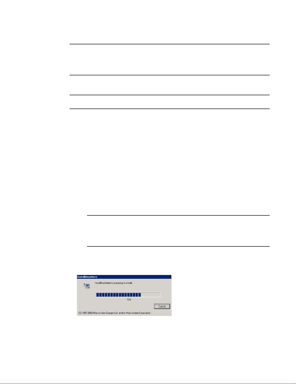
Using the Brocade Adapter Software Installer
NOTE
NOTE
NOTE
3
The software installer is not supported on VMware ESX platforms. However, you can use the
appropriate Brocade Adapter Software Installer to install HCM to a guest system (Windows, Linux, or
Solaris). To install adapter drivers on VMware systems, refer to “Using software installation scripts
and system commands” on page 89.
Use the following steps to install all software required for Brocade adapters with the GUI-based
installer program.
It is strongly recommended that you shut down the HCM application if it is running on your system.
1. Access the downloads pages of the adapters website using the following steps:
a. Go to the adapters website at www.brocade.com/adapters.
1. Navigate to the Downloads page.
2. Use one of these options to download software from the adapter’s Downloads page:
• View the appropriate download page for your host’s operating system by selecting an
operating system from the Download Individual Software Installers, Drivers, or Documents
list, then download the appropriate Brocade Adapter Software Installer or driver package
for your system.
Find the installer program for your system’s operating system and platform under
“Software installation and driver packages” on page 43.
• Select Download ISO Image to download an ISO 9660 (.iso) optical disk image containing
the Brocade Adapter Software Installer, individual driver packages, HCM, and
documentation. You can use this ISO file to create a CD that you can carry to your system
for installation.
For Windows systems only. Using a DVD created with the ISO image will automatically start
the correct installer program for your system. Make sure that the autorun feature is
enabled. If using this DVD, you do not need to execute the installer program command
(.exe or .bin) as explained in step 2.
2. Execute the appropriate Brocade Adapter Software Installer program (.exe or .bin file),
depending on your host’s operating system and platform.
A progress bar displays as files are extracted.
When all files are extracted, a Brocade Adapter Software title screen displays.
3. When the Brocade Software Installer Introduction screen displays (Figure 11), read the
recommendations and instructions, then click Next.
70 Brocade Adapters Installation and Reference Manual
53-1002144-01
Page 99

Using the Brocade Adapter Software Installer
NOTE
FIGURE 11 Brocade Adapter Installer Introduction screen
3
4. When the License Agreement screen displays, select I accept the terms of the License
Agreement, then click Next to continue.
5. If a backup directory exists for previously installed software, a “Found Backed up data”
message displays prompting you to restore old configurations. Select either to restore or not to
restore and continue installation. Refer to “HCM configuration data” on page 114 for more
information. If this message does not display, go on to step 6.
6.
If a screen such as the one in Figure 12 on page 72 displays listing software components already
installed on your system,
step 10.
select one of the following options, click Continue, then skip to
• Install with existing configuration. The installer compares each configured property and
keeps the original value if different than the default value.
• Install with default configuration. The installer upgrades the software and loads with
default configurations.
Existing versions of the adapter’s software components will be overwritten with the current
versions you are installing if you continue.
If this screen does not display, go on to step 7.
Brocade Adapters Installation and Reference Manual 71
53-1002144-01
Page 100

Using the Brocade Adapter Software Installer
NOTE
NOTE
3
FIGURE 12 Existing software components installed screen
7. If message box displays prompting you to close all HCM applications, close all applications if
they are still running, then click OK.
The Choose Install Set screen displays (Figure 13 or Figure 14).
This following screen displays for all adapter models except the Brocade 804 adapter.
.
FIGURE 13 Choose Install Set screen (models except the 804 adapter)
The following screen displays for the Brocade 804 adapter only.
72 Brocade Adapters Installation and Reference Manual
53-1002144-01
 Loading...