

Brocade 6520 QuickStart Guide
Complete the steps in this guide to install and set up your Brocade 6520 switch in a single-switch configuration using
EZSwitchSetup. See the Brocade 6520 Hardware Reference Manual and the Fabric OS Administrator’s Guide if you want
to choose a different setup.
1
Getting ready
Ensure that you have the items listed below. Write down the IP network values in the space provided.
3
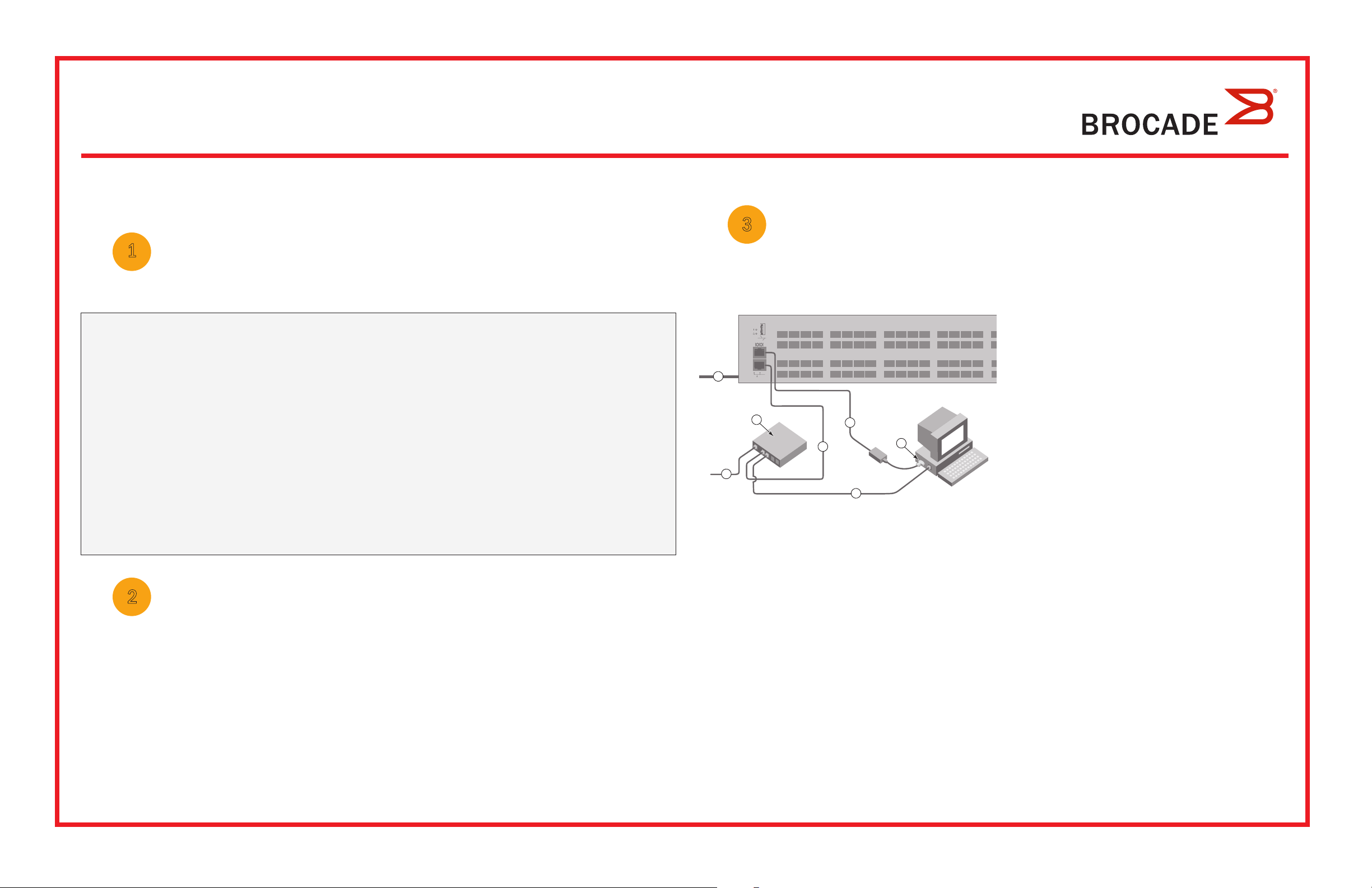
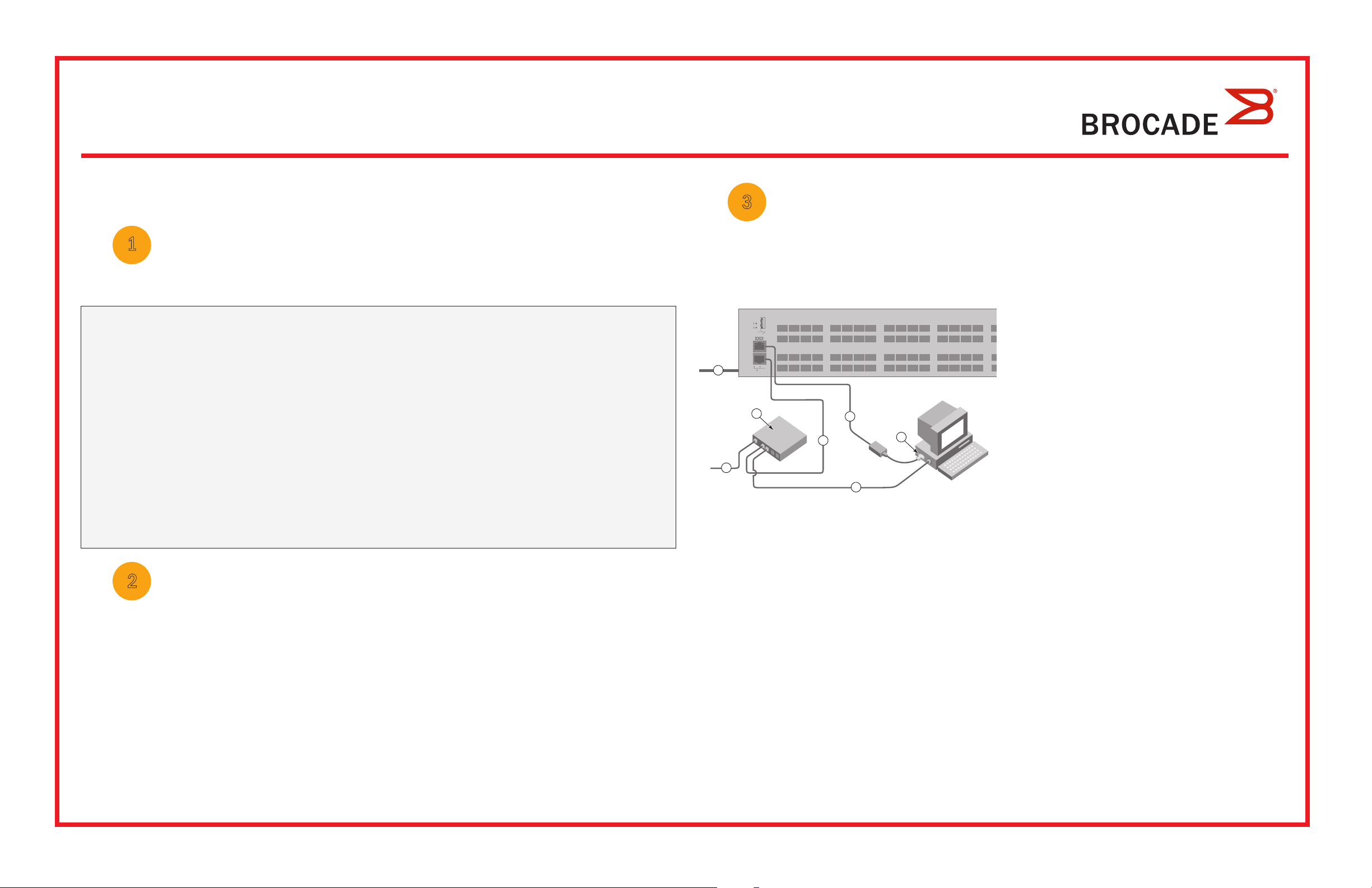
Powering up and connecting cables to the switch
The Connect Cables screen shows you the connections you need to make.
1. Connect the power cord to the switch and to a power
source (1). The power and status LEDs display amber then
green. This can take from one to three minutes.
Fixed IP address (IPv4 or IPv6) for the switch (no DHCP server): __________________________________________________
Subnet mask value: ______________________________________________________________________________________
Default Gateway value: ___________________________________________________________________________________
Brocade switch World Wide Name (WWN): located on the switch ID pullout: ________________________________________
Ethernet connection (hub or switch) Ethernet and Fibre Channel cables
EZSwitchSetup CD Setup computer
Host computer with an installed HBA Disk array
Standard screw driver Optical SFP+ transceivers
Browser that allows pop-up windows
2
Installing and starting EZSwitchSetup
1. Insert the EZSwitchSetup CD into the CD-ROM drive of your setup computer. The installer will autostart in about a minute.
2. Follow the EZSwitchSetup directions for installation. Installation will take a few minutes after you click OK.
3. Wait for EZSwitchSetup to start, which should happen automatically after it is installed.
For Windows and Linux instructions, refer to the EZSwitchSetup Administrator’s Guide.
2. Connect the switch and the setup computer to the
same LAN using Ethernet cables (3, 5) and an Ethernet
hub or switch (2). Be sure the Ethernet hub or switch is
1
2
6
4
3
5
7
connected to a power source (6).
3. If you want to use a serial connection for setup, connect
your setup computer COM port (7) to the serial port on the
switch using the serial cable shipped with the switch (4).
The serial connection settings are as follows:
• Bits per second: 9600
• Databits: 8
• Parity: none
• Stop bits: 1
• Flow control: none
4. Click Next.
• If you chose to use the Ethernet connection, the Discover Switch screen is displayed. Enter the switch WWN, following
the instructions on the Discover Switch screen. After completing switch discovery, the Set Switch IP Address screen
is displayed.
• If you chose to use the serial port connection, the Set Switch IP Address screen is immediately displayed.
4. On the EZSwitchSetup Introduction screen, choose the option that matches your setup configuration:
• Ethernet connection. This option uses the Ethernet LAN connection you will use for running EZSwitchSetup Manager.
• Direct connection to the switch with a serial cable.
Most users will find it more convenient to use the Ethernet connection.
5. Click Next. The Connect Cables screen is displayed.
4
Setting the switch IP address
1. Enter the required information on the Set Switch IP Address screen.
2. If prompted to install Active X or a version of the Java runtime environment, do so. Reboot the setup computer, if required.
3. Click Next.
The Confirm IP Address screen is displayed.
4. Click Next to confirm the addresses.
The Continue Configuration screen is displayed.
5. Click Continue with EZManager.
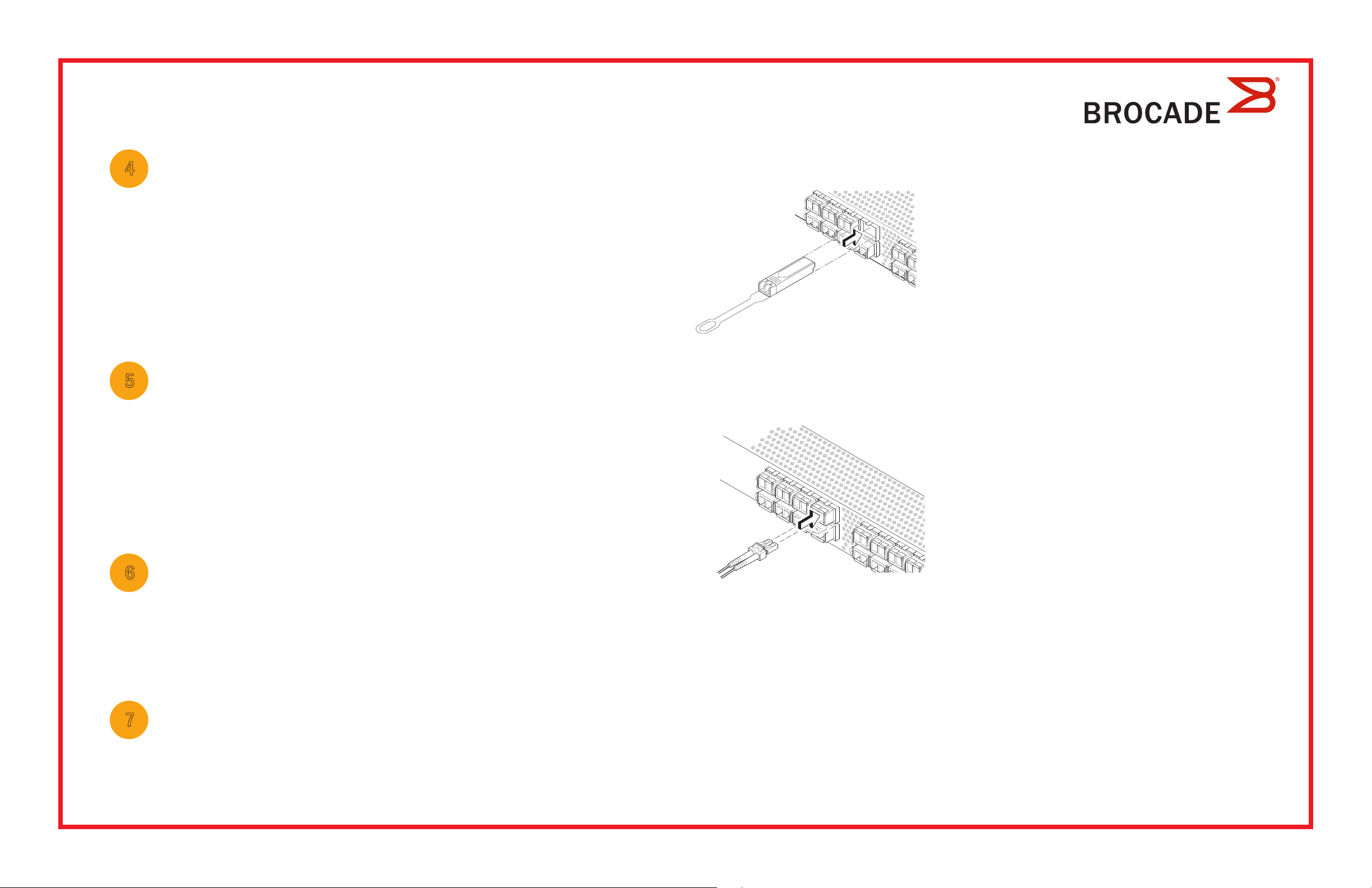
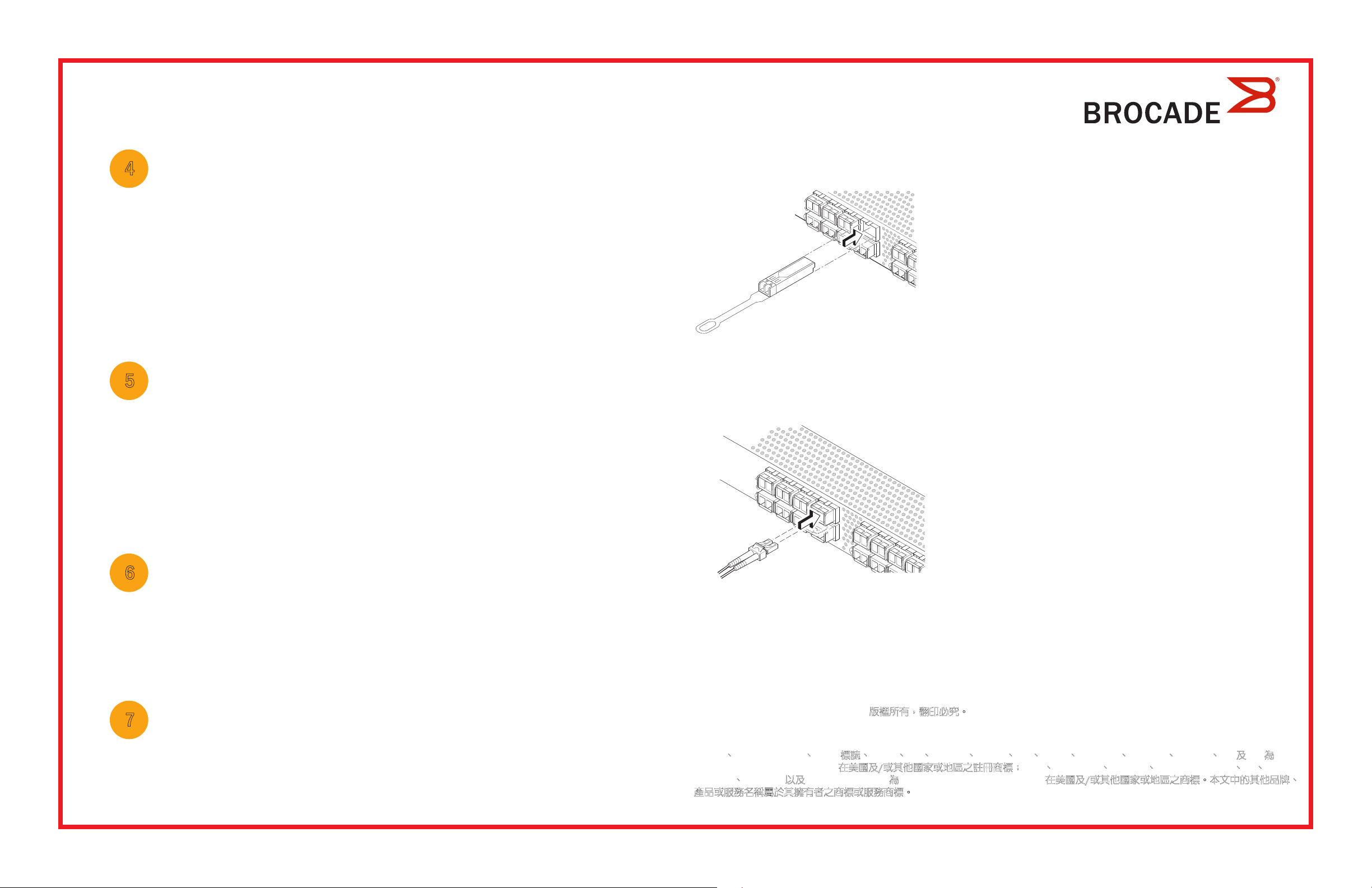
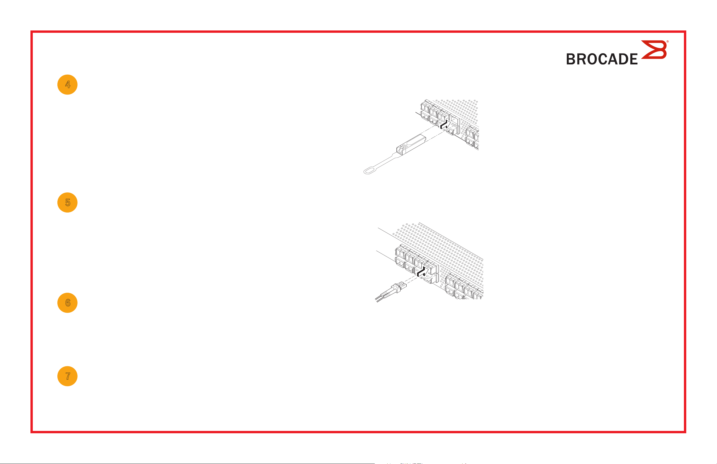
1. Install the SFP+ transceivers in the Fibre Channel ports on the switch to match the ports shown onscreen.
!
a. The 16 Gbps SFP+ transceivers have a long pull tab and no latching
wire bail. Remove any protector plugs from the SFP+ transceivers you
are going to use, and position and insert each SFP+ transceiver as
required (right side up in the top row of ports and upside down in the
bottom row of ports). Use the pull tab on the 16 Gbps SFP+ tranceivers
to help push the transceiver into the port.
If you are using 16 Gbps SFP+ transceivers, you may want to connect
the cable to the SFP+ first, and then insert them into the port as a unit.
If you are using 8 or 10 Gbps SFP+ transceivers, close the latching wire bail.
b. Repeat for the other ports.
5
Setting the switch password
1. Click Next on the EZManager Welcome to Switch Configuration screen.
The Set Parameters screen is displayed.
2. Create a new administrator account password in the Set Parameters screen.
3. Enter a new name for the switch (optional step).
4. Adjust the date and time for your time zone (optional step).
5. Click Next.
6
Configuring the zones and performing device selection
1. Select Typical Zoning on the Select Zoning screen and click Next.
Typical Zoning is the default zone configuration.
2. Enter the number and types of devices that you are connecting to the switch on the Device Selection screen.
EZSwitchSetup uses these values to automatically configure the ports on your switch.
2. Make the physical connections to your host and storage devices. Match the physical connections shown on the
Configure Ports and Connect Devices screen.
a. Remove plastic protector caps from the Fibre Channel cable ends (if any),
and position the cable connector so that it is oriented correctly.
!
3. The Finish screen will display this message: “Congratulations - you’ve successfully completed the setup!” If you used the
serial connection for setup, you can remove the serial cable.
Additional configuration options, such as custom zoning, are available from EZManager. See the EZSwitchSetup
Administrator’s Guide for more information on custom zoning, and other switch configuration and management options.
b. Insert the cable connector into the SFP+ transceiver until it is firmly
seated and the latching mechanism clicks.
c. The Configure Ports and Connect Devices screen shows missing,
valid, and invalid connections as you cable the switch. Note that it
can take up to 15 seconds for the connection to display as a valid
connection. Verify that the connections are all green and click Next.
7
Connecting devices
The Connect Devices screen displays a graphical representation of the switch with the device connections based on the
information that you entered when you configured zones and performed device selection. The screen will show all physical
connections as missing until you connect the devices that you specified.
© 2012 Brocade Communications Systems, Inc. All Rights Reserved.
53-1002706-01
*53-1002706-01*
Brocade, Brocade Assurance, the B-wing symbol, BigIron, DCX, Fabric OS, FastIron, MLX, NetIron, SAN Health, ServerIron, TurboIron, VCS, and VDX are
registered trademarks, and AnyIO, Brocade One, CloudPlex, Effortless Networking, ICX, NET Health, OpenScript, and The Ef fortless Network are trademarks
of Brocade Communications Systems, Inc., in the United States and/or in other countries. Other brands, products, or service names mentioned may be
trademarks of their respective owners.
Brocade 6520 快速入门指南
完成本指南中的步骤以使用 EZSwitchSetup 安装 Brocade 6520 交换机并以单一交换机配置进行设置。如果要选择不
同的设置,请参阅
1
确保您拥有下列物品。在提供的空白处记下 IP 网络值。
Brocade 6520 硬件参考手册和 Fabric OS 管理员指南
准备工作
。
连接电缆
3
启动和连接电缆至交换机
屏幕显示您需要进行的连接。
1. 将电源线连接至交换机和电源 (1)。电源和状态 LED 显
示琥珀色然后变为绿色。这可需要一至三分钟时间。
交换机的固定 IP 地址 (IPv4 或 IPv6) (无 DHCP 服务器): ______________________________________________________
子网掩码值: __________________________________________________________________________________________
默认网关值: __________________________________________________________________________________________
Brocade 交换机全球名称 (WWN):位于交换机 ID 印签上: ____________________________________________________
以太网连接(集线器或交换机) 以太网和光纤信道电缆
EZSwitchSetup 光盘 安装计算机
安装有 HBA 的主机计算机 磁盘阵列
普通螺丝刀 光纤 SFP+ 收发器
允许弹出窗口的浏览器
2
安装和启动 EZSwitchSetup
1. 将 EZSwitchSetup CD 插入安装计算机的 CD-ROM 驱动器中。安装程序将在一分钟左右自动开始。
2. 遵循 EZSwitchSetup 说明进行安装。单击确定之后,安装过程将需要几分钟时间。
3. 等待 EZSwitchSetup 启动,安装之后这将自动进行。对于 Windows 和 Linux 说明,请参考 EZSwitchSetup 管理员指南。
管理员指南
2. 使用以太网电缆(3、5)和以太网集线器或交换机(2)将
交换机和安装计算机连接到同一 LAN。请确保以太网集线
器或交换机连接到电源(6)。
1
2
6
4
3
5
7
3. 如果要使用串行连接进行安装,则使用交换机(4)随
附的串行电缆将安装计算机 COM 端口(7)连接到该交换
机上的串行端口。串行连接设置如下:
• 每秒位数:9600
• 数据位:8
• 奇偶校验:无
• 停止位:1
• 流量控制:无
4. 单击下一步
。
• 如果选择了使用以太网连接,则随即显示查找交换机屏幕。按照查找交换机屏幕上的说明输入交换机 WWN。
完成交换机查找之后,随即显示设置交换机 IP 地址屏幕。
• 如果选择了使用串行端口连接,则随即显示设置交换机 IP 地址屏幕。
4. 在 EZSwitchSetup 简介屏幕,请选择匹配您的设置配置的选项:
• 以太网连接。此选项使用您将在运行 EZSwitchSetup Manager 时所用的以太网 LAN 连接。
• 使用串行电缆直接连接到交换机。
大多数用户会发现,使用以太网连接更方便。
5. 单击下一步。随即显示连接电缆屏幕。
4
设置交换机 IP 地址
1. 在设置交换机 IP 地址屏幕上输入所需的信息。
2. 如果提示安装 Active X 或 Java Runtime 环境的版本,则请予以安装。如果需要,请重新引导安装计算机。
3. 单击下一步。
随即显示确认 IP 地址屏幕。
1. 在交换机的光纤信道端口中安装 SFP+ 收发器以匹配屏幕上所示的端口。
!
a. 该 16 Gbps SFP+ 收发器具有一个长的拔拉卡舌但没有闩锁线环。从要
使用的 SFP+ 收发器上卸下任何护塞,将每个 SFP+ 收发器按需定位并
插入(在顶排端口中右侧朝上,在底排端口中底侧朝上)。使用 16 Gbps
SFP+ 收发器上的拔拉卡舌将收发器推入端口中。
如果您使用 16 Gbps SFP+ 收发器,则可能先要将电缆连接到 SFP+,
然后将它们作为一个单元插入端口中。
4. 单击下一步确认该地址。
随即显示继续配置屏幕。
5. 单击继续 EZManager。
5
设置交换机密码
1. 在EZManager 欢迎使用交换机配置屏幕,单击下一步。
随即显示设置参数屏幕。
2. 在设置参数屏幕,创建新管理员帐户密码。
3. 输入交换机的新名称(可选步骤)。
4. 调整您所在时区的日期和时间(可选步骤)。
5. 单击下一步。
6
配置区域并执行设备选择
1. 在选择分区
“典型分区”是默认的区域配置。
2. 在设备选择屏幕上输入您将要连接至交换机的设备数和类型。EZSwitchSetup 使用这些值在您的交换机上自动配
屏幕上选择典型分区,然后单击下一步 。
如果您使用的是 8 或 10 Gbps SFP+ 收发器,则请合上闩锁线环。
b. 对其他端口重复此步骤。
2. 对主机和存储设备进行物理连接。使配置端口和连接设备
a. 从光纤信道电缆终端卸下任何塑料护帽(如果有),然后定位电缆
连接器以便正确对齐。
b. 将电缆连接器插入 SFP+ 收发器直到稳固就位并且闩锁机件发出咔
!
3. 完成
EZManager 还有可用的附加配置选项例如自定义分区。请参阅 EZSwitchSetup 管理员指南了解有关自定义分区的更
屏幕将显示此消息:“Congratulations - you’ve successfully completed the setup!”(祝贺—您已成功完成安装!)
如果您使用了串行连接进行设置,则可以移除串行电缆。
多信息、以及其他交换机配置及管理选项。
嗒声。
c. 在您为交换机布线过程中,配置端口和连接设备
效、和无效连接。请注意,可能需要 15 秒钟时间连接才会显示为
有效连接。请确认所有连接均显示为绿色,然后单击下一步。
屏幕所示的物理连接匹配。
屏幕显示丢失、有
管理员指南
7
连接设备
连接设备
的设备之前,此屏幕将所有物理连接显示为 missing(丢失)。
屏幕根据在您配置区域和执行设备选择时输入的信息,以图形方式显示交换机与设备的连接。在您连接所指定
© 2012 Brocade Communications Systems, Inc. 保留所有权利。
53-1002706-01
*53-1002706-01*
Brocade、Brocade Assurance、B-wing 符号、BigIron、DCX、Fabric OS、FastIron、MLX、NetIron、SAN Health、ServerIron、TurboIron、VCS、
和
VDX 是 Brocade Communications Systems, Inc. 在美国和/或其他国家或地区的注册商标,并且 AnyIO、Brocade One、CloudPlex、
Effortless Networking、ICX、NET Health、OpenScript、和
地区的商标。 所提及的其他品牌、产品、或服务名称则可能是其各自所有者的商标。
Effortless Network 是 Brocade Communications Systems, Inc. 在美国和/或其他国家或

Brocade 6520 快速啟動指南
完成本指南中的步驟,於單一交換機組態中使用 EZSwitchSetup 安裝及設定您的 Brocade 6520 交換機。
如果您想選擇不同設定,請參閱 與 。
1
準備開始
請確定您已備妥下列項目。請在所提供的空白處寫下 IP 網路值。
交換機的固定 IP 位址 (IPv4 或 IPv6) (無 DHCP 伺服器): ______________________________________________________
子網路遮罩值: ________________________________________________________________________________________
預設閘道值: __________________________________________________________________________________________
Brocade 6520 硬體參考手冊 Fabric OS 管理員指南
3
打開電源並將纜線連接至交換機
Connect Cables (連接纜線) 畫面會顯示您必須連接的連線。
1
1. 將電源線連接至交換機及電源 (1)。電源與狀態 LED
會顯示琥珀色,然後顯示綠色。這需要一到三分鐘的時間。
2. 使用乙太網路線 (3、5) 以及乙太網路集線器或交
換機 (2),將交換機與安裝電腦連接至相同的區域網路。
請確定乙太網路集線器或交換機已連接電源 (6)。
3. 如果您要使用序列連線進行安裝,請使用與交換機 (4)
內附的序列纜線,將您的安裝電腦 COM 連接埠 (7) 連接至
交換機上的序列埠。序列連線的設定如下:
Brocade 交換機的 World Wide Name (WWN):位於交換機 ID 標籤上: __________________________________________
乙太網路連線 (集線器或交換機) 乙太網路與光纖通道纜線
EZSwitchSetup 光碟 安裝電腦
已安裝 HBA 的主機電腦 磁碟陣列
標準螺絲起子 光纖 SFP+ 收發器
允許彈出視窗的瀏覽器
2
安裝並啟動 EZSwitchSetup
1. 將 EZSwitchSetup 光碟放入您的安裝電腦中的光碟機內。安裝程式將在約一分鐘內自動啟動。
2. 請遵循 EZSwitchSetup 指示進行安裝。在您按一下 OK (確定) 之後,安裝過程約需幾分鐘的時間。
3. 等待 EZSwitchSetup 開始執行,它會在完成安裝後自動執行。
有關 Windows 及 Linux 的說明,請參閱 EZSwitchSetup
4. 在 EZSwitchSetup 簡介畫面中,請選擇符合您的設定組態的選項:
• 乙太網路連線。此選項為您將用來執行 EZSwitchSetup 管理員的乙太區域網路連線。
管理員指南
。
2
3
6
4. 按一下 Next (下一步)。
4
7
5
• 每秒傳輸位元:9600
• 資料位元:8
• 同位檢查:無
• 停止位元:1
• 流程控制:無
• 如果您選擇使用乙太網路連線,將會顯示 Discover Switch (發線交換機) 畫面。輸入交換機的 WWN,然後遵循
Discover Switch (發現交換) 畫面的指示。完成發現交換機的步驟之後,將會顯示 Set Switch IP Address
(設定交換機 IP 位址) 畫面。
• 如果您選擇使用序列連接埠連接,會立即顯示 Set Switch IP Address (設定交換機 IP 位址) 畫面。
• 使用序列纜線直接連接交換機。
大多數使用者會發現使用乙太網路連線更為便利。
5. 按一下 Next (下一步)。 隨即顯示 Connect Cables (連接纜線) 畫面。
4
設定交換機 IP 位址
1. 在 Set Switch IP Address (設定交換機 IP 位址 ) 畫面中輸入必要的資訊。
2. 畫面中會提示您安裝 Active X 或某個版本的 Java 執行時期環境,請遵循提示進行安裝。如有需要,請重新啟動
安裝電腦。
3. 按一下 Next (下一步)。
隨即顯示Confirm IP Address (確認 IP 位址) 畫面。
4. 按一下 Next (下一步) 以確認位址。
隨即顯示 Continue Configuration (繼續設定) 畫面。
5. 按一下 Continue with EZManager (繼續使用 EZManager)。
1. 將 SFP+ 收發器安裝於交換機上的光纖通道連接埠以符合螢幕上所顯示的連接埠。
!
a. 16 Gbps SFP+ 收發器上有一個長拉柄,沒有閂鎖纜線橫桿。移除您要
使用的 SFP+ 收發器上的所有保護蓋,並依照需要調整 SFP+ 收發器的
位置並將其插入 (連接上排的連接埠時必須右側朝上,連接下排的連接
埠時必須顛倒過來)。利用 16 Gbps SFP+ 收發器上的拉柄以便將收發器
插入連接埠。
如果您要使用 16 Gbps SFP+ 收發器,可能會想要先將纜線連接至 SFP+,
再將它插入連接埠形成一個單元。
如果您要使用 8 或 10 Gbps SFP+收發器,請關閉閂鎖纜線橫桿。
b. 在其他連接埠上重複執行此動作。
5
繼續使用 EZManager
1. 在 EZManager 上的 Welcome to Switch Configuration (歡迎至交換機設定) 的畫面上按一下 Next (下一步) 。
隨即顯示 Set Parameters (設定參數) 畫面。
2. 在 Set Parameters (設定參數) 中建立新的管理員帳戶密碼。
3. 輸入新的交換機名稱 (選擇性步驟)。
4. 調整您的時區的日期與時間 (選擇性步驟)。
5. 按一下 Next (下一步)。
6
設定區域並執行裝置選取
1. 在 Select Zoning (選取區域) 畫面中選取 Typical Zoning (典型區域) 並按一下 Next (下一步)。
預設區域設定為典型區域。
2. 在您要連線之交換機的 Device Selection (裝置選取) 畫面上輸入裝置類型。
EZSwitchSetup 會使用這些值自動組態交換機的連接埠。
2. 實體連接您的主機與儲存裝置。實體連線必須符合 Configure Ports and Connect Devices (設定連接埠及連接裝置)
畫面所示的連接方式。
a. 將光纖通道纜線端的塑膠保護蓋 (如果有的話) 取下,然後調整纜線接
頭的位置以使其方向正確。
!
3. Finish (完成) 畫面將顯示此訊息:Congratulations - you’ve successfully completed the setup! (恭喜 - 您已成功完成設定!),
如果您使用序列連線進行設定,則可移除序列纜線。
管理員指南
請參閱 EZSwitchSetup
瞭解更多有關自訂區域與其他交換機組態和管理選項的資訊。
b. 將纜線接頭插入 SFP+ 收發機直到確實固定,而且閂鎖機構發出咔嚓聲。
c. 當您連接或拔除交換機的纜線時,Configure Ports and Connect Devices
(設定連接埠及連接裝置) 畫面會顯示中斷、有效及無效的連線。請注意,
插入纜線之後最長約需 15 秒才會將該連線顯示為有效的連線。請檢查
連線是否均顯示為綠色,然後按一下 Next (下一步 )。
7
連接裝置
Connect Devices (連接裝置) 畫面會依據您在設定區域並執行裝置選擇時所輸入的資訊,以圖形化的方式顯示交換機
與裝置的連線。此畫面將會顯示所有實體連線都是中斷的,直到您連接所指定的裝置為止。
© 2012 Brocade Communications Systems, Inc. 版權所有,翻印必究。
53-1002706-01
*53-1002706-01*
Brocade、Brocade Assurance、B-wing 標誌、BigIron、DCX、Fabric OS、FastIron、MLX、NetIron、SAN Health、ServerIron、TurboIron、VCS 及 VDX 為
Brocade Communications Systems, Inc. 在美國及
NET Health、OpenScript 以及 The Effortless Network 為 Brocade Communications Systems, Inc. 在美國及/或其他國家或地區之商標。本文中的其他品牌、
產品或服務名稱屬於其擁有者之商標或服務商標。
/或其他國家或地區之註冊商標;AnyIO、Brocade One、CloudPlex、Effortless Networking、ICX、
Guide de démarrage rapide Brocade 6520
Effectuez les étapes qui figurent dans ce guide pour installer et configurer votre commutateur Brocade 6520 en
configuration à un seul commutateur à l'aide d'EZSwitchSetup. Voir le Manuel de référence du matériel Brocade 6520
et le Guide de l'administrateur du système d'exploitation de la matrice si vous souhaitez choisir une autre configuration.
3
Mise sous tension du commutateur et connexion des câbles
1
Préparation
Assurez-vous que vous disposez des éléments répertoriés dans la liste ci-dessous. Notez les valeurs de réseau IP dans
l'espace prévu à cet effet.
Adresse IP fixe (IPv4 ou IPv6) du commutateur (pas de serveur DHCP) : __________________________________________
Valeur de masque de sous-réseau : ________________________________________________________________________
Valeur de passerelle par défaut : ___________________________________________________________________________
Nom universel (WWN) du commutateur Brocade : situé sur la languette d'identification du commutateur : ______________
Connexion Ethernet (concentrateur ou commutateur) Câbles Ethernet et Fibre Channel
CD EZSwitchSetup Configuration de l'ordinateur
Ordinateur hôte avec HBA installé Matrice de disques
Tournevis standard Émetteurs - récepteurs SFP+ optiques
Navigateur qui permet l'affichage de fenêtres pop-up
au commutateur
L'écran Connecter les câbles vous indique les connexions à établir.
1
2
6
4
3
5
7
1. Branchez le cordon d'alimentation au commutateur et
à la source d'alimentation (1). Les voyants d'alimentation
et d'état deviennent orange puis vert. Cela peut prendre
une à trois minutes.
2. Branchez le commutateur et l'ordinateur de
configuration au même réseau local à l'aide des câbles
Ethernet (3, 5) et d'un commutateur ou concentrateur
Ethernet (2). Assurez-vous que le commutateur ou le
concentrateur Ethernet est branché à une source
d'alimentation électrique (6).
3. Si vous souhaitez utiliser une connexion série pour la
configuration, connectez le port COM de votre ordinateur
de configuration (7) au port série du commutateur en
utilisant le câble série livré avec le commutateur (4).
Les paramètres de connexion série sont les suivants :
• Bits par seconde : 9600
• Bits de données : 8
• Parité : aucune
• Bits d'arrêt : 1
2
Installation et démarrage d'EZSwitchSetup
1. Insérez le CD EZSwitchSetup dans le lecteur CD-ROM de votre ordinateur de configuration. Le programme d'installation
démarrera automatiquement dans environ une minute.
2. Suivez les instructions d'installation d'EZSwitchSetup. L'installation prendra quelques minutes après que vous aurez
cliqué sur OK.
3. Attendez que EZSwitchSetup démarre, ce qui devrait se produire automatiquement une fois le programme installé.
Pour obtenir les instructions Windows et Linux, consultez le Guide de l'administrateur d'EZSwitchSetup.
4. Sur l'écran de Présentation d'EZSwitchSetup, sélectionnez l'option qui correspond à votre configuration :
• Connexion Ethernet. Cette option utilise la connexion LAN Ethernet que vous utiliserez pour exécuter EZSwitchSetup Manager.
• Connexion directe au commutateur avec un câble série.
La plupart des utilisateurs préféreront se servir de la connexion Ethernet.
5. Cliquez sur Suivant. L'écran Connecter les câbles s'affiche.
• Contrôle du flux : aucun
4. Cliquez sur Suivant.
• Si vous choisissez d'utiliser la connexion Ethernet, l'écran Découvrir le commutateur s'affiche. Saisissez le WWN du
commutateur selon les instructions à l'écran Découvrir le commutateur. Une fois la découverte du commutateur
terminée, l'écran Définir l'adresse IP du commutateur s'affiche.
• Si vous choisissez d'utiliser la connexion port série, l'écran Définir l'adresse IP du commutateur s'affiche
immédiatement.
4
Définition de l'adresse IP du commutateur
1. Saisissez les informations requises à l'écran Définir l'adresse IP du commutateur.
2. Si vous êtes invité à installer Active X ou une version de l'environnement Java Runtime, faites-le. Redémarrez l'ordinateur
de configuration, si nécessaire.
3. Cliquez sur Suivant.
L'écran Confirmer l'adresse IP s'affiche.
4. Cliquez sur Suivant pour confirmer les adresses.
L'écran Poursuivre la configuration s'affiche.
5. Cliquez sur Continuer avec EZManager.
1. Installez les émetteurs-récepteurs SFP+ dans les ports Fibre Channel du commutateur pour y faire correspondre les
ports affichés à l'écran.
!
a. Les émetteurs-récepteurs SFP+ 16 Gb/s présentent une longue languette
de préhension et aucune anse de verrouillage. Retirez toutes les fiches de
protection des émetteurs-récepteurs SFP+ que vous allez utiliser et insérez
chaque émetteur-récepteur SFP+ selon les instructions (à l'endroit dans la
rangée de ports supérieure et à l'envers dans la rangée inférieure de
ports). Utilisez la languette de préhension des émetteurs-récepteurs SFP+
16 Gb/s pour pousser l'émetteur-récepteur dans son port.
Si vous utilisez des émetteurs-récepteurs SFP+ à 16 Gb/s, vous voudrez
peut-être connecter le câble au SFP+ d'abord et ensuite les insérer dans le
port en bloc.
Si vous utilisez des émetteurs-récepteurs SFP+ 8 ou 10 Gb/s, fermez le
loquet de verrouillage.
b. Répétez cette procédure pour les autres ports.
5
Définition du mot de passe du commutateur
1. Cliquez sur Suivant à l'écran d' EZManager Bienvenue à la configuration du commutateur.
L'écran Définir les paramètres s'affiche.
2. Créez un nouveau mot de passe pour le compte d'administrateur à l'écran Définir les paramètres.
3. Saisissez un nouveau nom pour le commutateur (étape facultative).
4. Réglez la date et l'heure selon votre fuseau horaire (étape facultative).
5. Cliquez sur Suivant.
6
Configuration des zones et sélection de périphériques
1. Sélectionnez Fuseau typique à l'écran Sélectionner un fuseau et cliquez sur Suivant.
Il s'agit de la configuration de zone par défaut.
2. Saisissez le nombre et les types de périphériques que vous connectez au commutateur à l'écran Sélection de
périphériques. EZSwitchSetup utilise ces valeurs pour configurer automatiquement les ports sur votre commutateur.
7
Connexion de périphériques
L'écran Connecter des périphériques affiche une représentation graphique du commutateur avec les connexions de
périphérique selon les informations que vous avez entrées lors de la configuration des zones et la sélection de périphériques.
L'écran affichera toutes les connexions physiques comme manquantes tant que vous n'aurez pas connecté les périphériques
spécifiés.
2. Établissez les connexions physiques à votre hôte et aux périphériques de stockage. Faites correspondre les connexions
physiques affichées à l'écran Configurer les ports et connecter les périphériques.
a. Retirez les capuchons de protection en plastique des extrémités de
câble Fibre Channel (le cas échéant) et disposez le connecteur de
façon à l'orienter correctement.
!
3. L'écran Terminer affichera ce message : “Congratulations - you’ve successfully completed the setup!” (« Félicitations vous avez réussi la configuration ! »). Si vous avez utilisé la connexion série pour la configuration, vous pouvez retirer le
câble série.
Des options de configuration supplémentaires, telles que la définition de zone personnalisée, sont disponibles depuis
EZManager. Voir le Guide de l'administrateur d'EZSwitchSetup pour en savoir plus sur la définition personnalisée des
zones, ainsi que d'autres options de gestion et de configuration de commutateur.
© 2012 Brocade Communications Systems, Inc. Tous droits réservés.
53-1002706-01
b. Insérez le connecteur de câble dans l'émetteur-récepteur SFP+
jusqu'à ce qu'il soit bien installé et que le mécanisme de verrouillage
s'enclenche.
c. L'écran Configurer des ports et connecter des périphériques affiche
les connexions manquantes, valides et non valides lorsque vous
câblez le commutateur. Notez que jusqu'à 15 secondes peuvent
s'écouler avant l'affichage de la connexion en tant que connexion
valide. Vérifiez que les voyants des connexions sont tous verts, puis
cliquez sur Suivant.
*53-1002706-01*
Brocade, Brocade Assurance, le symbole B-wing, BigIron, DCX, Fabric OS, FastIron, MLX, NetIron, SAN Health, ServerIron, TurboIron, VCS et VDX sont des
marques déposées et AnyIO, Brocade One, CloudPlex, Effor tless Networking, ICX, NET Health, OpenScript et The Effortless Network sont des marques de
Brocade Communications Systems, Inc. aux États-Unis et/ou dans d'autres pays. Les autres marques, produits ou noms de services cités peuvent être
des marques de leurs détenteurs respectifs.
 Loading...