

Page 1

DELL™ OPTIPLEX™ 7010 TECHNICAL GUIDEBOOK VER1.2
TM
DELL
TM
OPTIPLEX 7010
TECHNICAL GUIDEBOOK
INSIDE THE OPTIPLEX 7010
1
Page 2

TABLE OF CONTENTS
OVERVIEW
Mini Tower Computer (MT) View 3-4
Desktop Computer (DT) View 5-6
Small Form Factor Computer (SFF) View 7-8
Ultra Small Form Factor Computer (USFF) View
MARKETING SYSTEM CONFIGURATIONS
Operating System, Chipset 11
Processor 12
Memory 13
Drives and Removable Storage, 14
System Board Connectors 15
Graphics/Video Controller 16
External Ports/Connectors 16
9-10
Communications—Network Adapter (NIC), Wireless 17
Audio and Speakers, Keyboard and Mouse 17
Security, Service and Support, Software 18
DETAILED ENGINEERING SPECIFICATIONS
System Dimensions (Physical) 19
System Board Connector Maximum Allowable Dimensions 19
System Level Environmental and Operating Conditions 20
Power 21-22
Audio 23
Communications 23-28
Graphics/Video Controller 29-30
Hard Drives 31-38
Optical Drive 39-40
Media Card Reader
BIOS Defaults 42
Chassis Enclosure and Ventilation Requirements 43
Acoustic Noise Emission Information 44-47
41
Page 3
DELL™ OPTIPLEX™ 7010 TECHNICAL GUIDEBOOK VER1.2
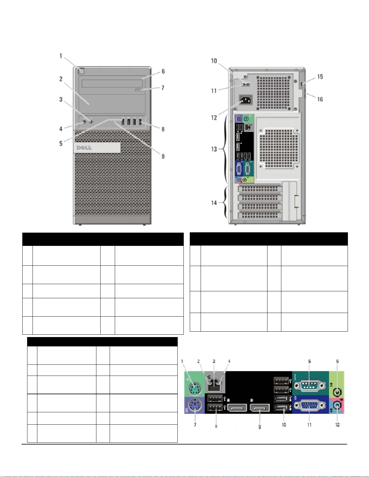
MINI TOWER COMPUTER (MT) VIEW
FRONT VIEW
1 Power Button, Power
6 Optical Drive (optional)
Light
2 Optical Drive Bay
(optional)
7 Optical Drive Eject
Button
3 Headphone Connector 8 USB 2.0 Connectors (2)
4 Microphone
9 Drive Activity Light
Connector
5 USB 3.0 Connectors
(2)
BACK PANEL CONNECTORS
PS2 Mouse Con-
1
nector
SP2 Keyboard Con-
7
nector
2 Link Integrity Light 8 USB2.0 Connectors (2)
3 Network Connector 9
Network Activity
4
Light
DisplayPort Connector
(2)
USB2.0 Connectors (2)
10
USB3.0 Connectors (2)
BACK VIEW
10 Power Supply Diag-
nostic Light
11 Power Supply Diag-
nostic Button
14 Expansion Card Slots
(4)
15 Kensington / Noble
Security Cable Slot
12 Power Connectors 16 Padlock Ring
13 Back Panel Connect-
ors
5 Serial Connector 11 VGA Connector
6 Line-out Connector 12
Line-in/Microphone
Connector
3
Page 4
DELL™ OPTIPLEX™ 7010 TECHNICAL GUIDEBOOK VER1.2
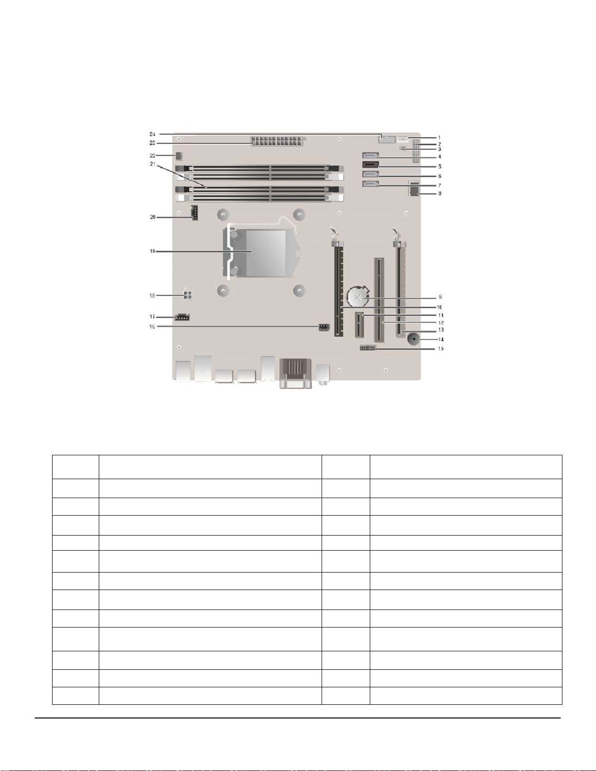
MT System Board Components
Num-
ber
Name
1 Internal Speaker Connector (INT_SPKR) 13 PCI-e x16 (wire x4) Connector (SLOT4)
2 Front IO Connector (FRONTPANEL) 14 Buzzer (BEEP)
3 Thermal Sensor Connector (THRM_2) 15 LPC Debug Connector (LPC_DEBUG)
4 SATA 0 Connector (SATA0) 16 Intrusion Switch Connector (INTRUDER)
5 SATA 1 Connector (SATA1) 17 System Fan Connector (FAN_HDD)
6 SATA 2 Connector (SATA2) 18 P2 Power Connector (12V_PWRCONN)
7 SATA 3 Connector (SATA3) 19 Processor Socket (N/A)
8 Internal USB Connector (INT_USB) 20 CPU fan Connector (FAN_CPU)
9 Battery Connector (BATTERY) 21
10 PCI-e x16 Connector (SLOT1) 22 Power Switch Connector (PWR_SW)
11 PCI-e x1 Connector (SLOT2) 23 P1 Power Connector (POWER)
12 PCI Connector (SLOT3) 24 Front USB3.0 Connector (Front _USB )
Num-
ber
Name
Memory Connectors (DIMM1, DIMM2,
DIMM3, DIMM4)
4
Page 5

DELL™ OPTIPLEX™ 7010 TECHNICAL GUIDEBOOK VER1.2
DESKTOP COMPUTER (DT) VIEW
FRONT VIEW
1 Optical Drive 5 USB 3.0 Connectors (2)
Optical Drive Eject
2
Button
Power Button, Power
3
Light
6 Microphone Connector
7 Headphone Connector
4 USB 2.0 Connectors (2) 8 Drive Activity Light
BACK PANEL CONNECTORS
PS2 Mouse
1
Connector
PS2 Keyboard
7
Connector
2 Link Integrity Light 8 USB2.0 Connectors (2)
BACK VIEW
9 Padlock Ring 13
10 Kensington / Noble
Security Cable Slot
14
11 Power Connectors 15
12 Back Panel
Connectors
Expansion Card Slots
(4)
Power Supply
Diagnostic Light
Power Supply
Diagnostic Button
3 Network Connector 9
Network Activity
4
Light
DisplayPort Connector
(2)
USB2.0 Connectors (2)
10
USB3.0 Connectors (2)
5 Serial Connector 11 VGA Connector
6 Line-out Connector 12
Line-in/Microphone
Connector
5
Page 6
DELL™ OPTIPLEX™ 7010 TECHNICAL GUIDEBOOK VER1.2
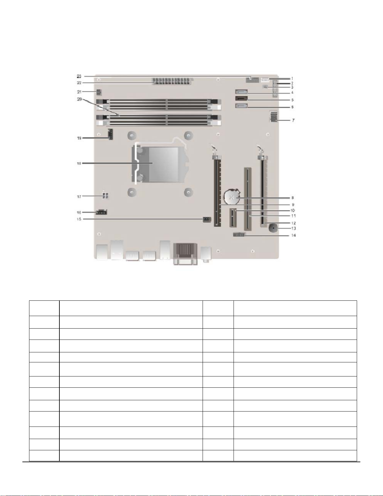
DT System Board Components
Num-
ber
Name
1 Internal Speaker Connector (INT_SPKR) 12 PCI-e x16 (wire x4) Connector (SLOT4)
2 Front IO Connector (FRONTPANEL) 13 Buzzer (BEEP)
3 Thermal Sensor Connector (THRM_2) 14 LPC Debug Connector (LPC_DEBUG)
4 SATA 0 Connector (SATA0) 15 Intrusion Switch Connector (INTRUDER)
5 SATA 1 Connector (SATA1) 16 System Fan Connector (FAN_HDD)
6 SATA 2 Connector (SATA2) 17 P2 Power Connector (12V_PWRCONN)
7 Internal USB Connector (INT_USB) 18 Processor Socket (N/A)
8 Battery Connector (BATTERY) 19 CPU fan Connector (FAN_CPU)
9 PCI-e x16 Connector (SLOT1) 20
10 PCI-e x1 Connector (SLOT2) 21 Power Switch Connector (PWR_SW)
11 PCI Connector (SLOT3) 22 P1 Power Connector (POWER)
Num-
ber
Name
Memory Connectors (DIMM1, DIMM2,
DIMM3, DIMM4)
23 Front USB3.0 Connector (Front _USB )
6
Page 7

DELL™ OPTIPLEX™ 7010 TECHNICAL GUIDEBOOK VER1.2
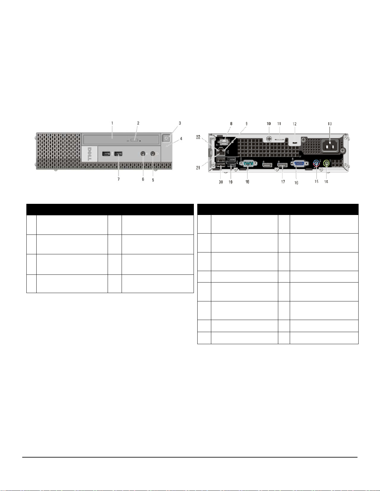
SMALL FORM FACTOR COMPUTER (SFF) VIEW
FRONT VIEW
1 Optical Drive 5 USB 3.0 Connectors (2)
2 Optical Drive Eject
6 Microphone Connector
Button
3 Power Button, Power
Light
7 Headphone Connector
4 USB 2.0 Connectors (2) 8 Drive Activity Light
BACK PANEL CONNECTORS
1 PS2 Mouse
7 PS2 Keyboard Connector
Connector
2 Serial Connector 8 VGA Connector
3 Link Integrity Light 9 DisplayPort Connector(2)
4 Network Connector 10 USB 2.0 Connectors (2)
BACK VIEW
9 Padlock Ring 13 Power Supply
Diagnostic Light
10 Kensington / Noble
Security Cable Slot
14 Back Panel
Connectors
11 Power Connectors 15 Expansion Card Slots
(2)
12 Power Supply
Diagnostic Button
5 Network Activity Light
USB2.0 Connectors (2)
11
USB3.0 Connectors (2)
6 Line-out Connector 12 Line-in/Microphone Con-
nector
7
Page 8
DELL™ OPTIPLEX™ 7010 TECHNICAL GUIDEBOOK VER1.2
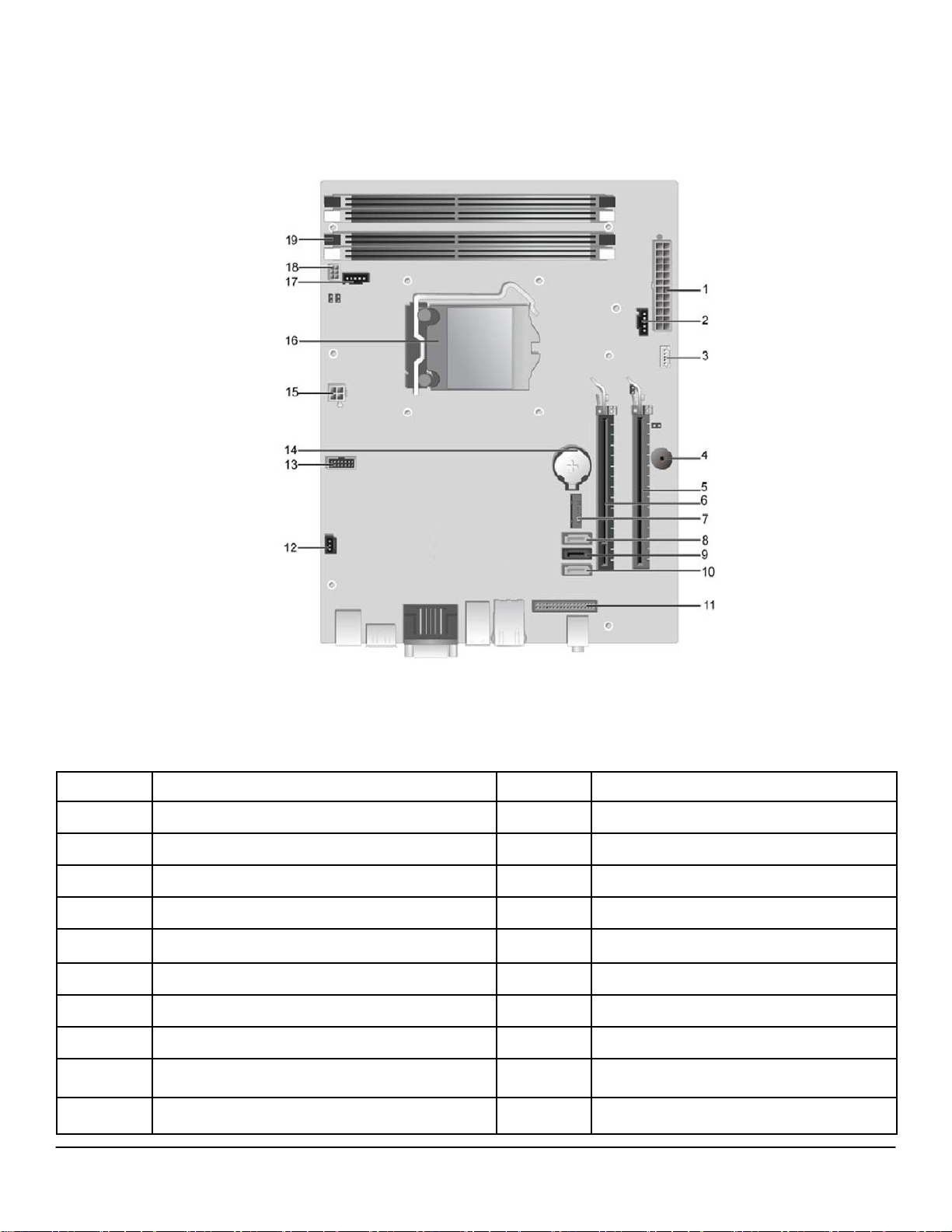
SFF System Board Components
Number Name Number Name
1 P1 power Connector (POWER) 11 Front IO Connector (FRONTPANEL)
2 System fan Connector (FAN_HDD) 12 Intrusion Switch Connector (INTRUDER)
3 Internal Speaker Connector (INT_SPKR) 13 LPC debug Connector (LPC_DEBUG)
4 Buzzer (BEEP) 14 Battery Connector (BATTERY)
5 PCI-e x16 (wire x4) Connector (SLOT2) 15 P2 Power Connector (12V_PWRCONN)
6 PCI-e x16 Connector (SLOT1) 16 Processor Connector (N/A)
7 Front USB3.0 Connector (Front _USB ) 17 CPU Fan Connector (FAN_CPU)
8 SATA 2 Connector (SATA2) 18 Power Switch Connector (PWR_SW)
9 SATA 1 Connector (SATA1) 19 Memory Connectors (DIMM1, DIMM2,
DIMM3, DIMM4)
10 SATA 0 Connector (SATA0)
8
Page 9
DELL™ OPTIPLEX™ 7010 TECHNICAL GUIDEBOOK VER1.2
ULTRA SMALL FORM FACTOR COMPUTER (USFF) VIEW
FRONT VIEW
1 Optical Drive 5 Headphone Connector
2 Optical Drive Eject
6 Microphone Connector
Button
3 Power Button, Power
Light
7 USB 3.0 Connectors (2)
4 Drive Activity Light
BACK VIEW
Wi-Fi Antenna
8
(optional)
9 Network Activity Light 16
10 Captive Thumbscrew 17
Line-in/ Microphone
15
Connector
VGA Connector
DisplayPort Connector
(2)
11 Padlock Ring 18 Serial Connector
Kensington / Noble
12
Security Cable Slot
13 Power Connector 20
USB 3.0 Connectors
19
(2)
USB 2.0 Connectors
(2)
14 Line-Out Connector 21 Network Connector
22 Link Integrity Light
9
Page 10

DELL™ OPTIPLEX™ 7010 TECHNICAL GUIDEBOOK VER1.2
USFF System Board Components
Number Name Number Name
1 Front Panel Connector (FRONTPANEL) 9
2 Memory Connector (DIMM_1,DIMM_2) 10 SATA 1 Connector (SATA1)
3 CPU Fan Connector (FAN_CPU) 11 P1 Power Connector (POWER)
4 Internal Speaker Connector (INT_SPKR) 12 SATA 0 Connector (SATA0)
5 Front IO Connector (F_USB_AUDIO) 13
6 System Fan Connector (FAN_HDD) 14 LPC Debug Connector (LPC_DEBUG)
7 Mini-PCI Socket (PCIE_MINICARD) 15 P2 Power Connector (12V_PWRCONN)
8 Front USB3.0 connector (Front USB) 16 Processor socket (N/A)
17 Battery Connector (BATTERY)
HDD-ODD Power Connector
(HDD_ODD_POWER)
Intrusion Switch Connector
(INTRUDER)
10
Page 11
DELL™ OPTIPLEX™ 7010 TECHNICAL GUIDEBOOK VER1.2
MARKETING SYSTEM CONFIGURATIONS
NOTE: O erings may vary by country. For more information regarding the confi guration of your computer, click
Start>Help and Support and select the option to view information about your computer.
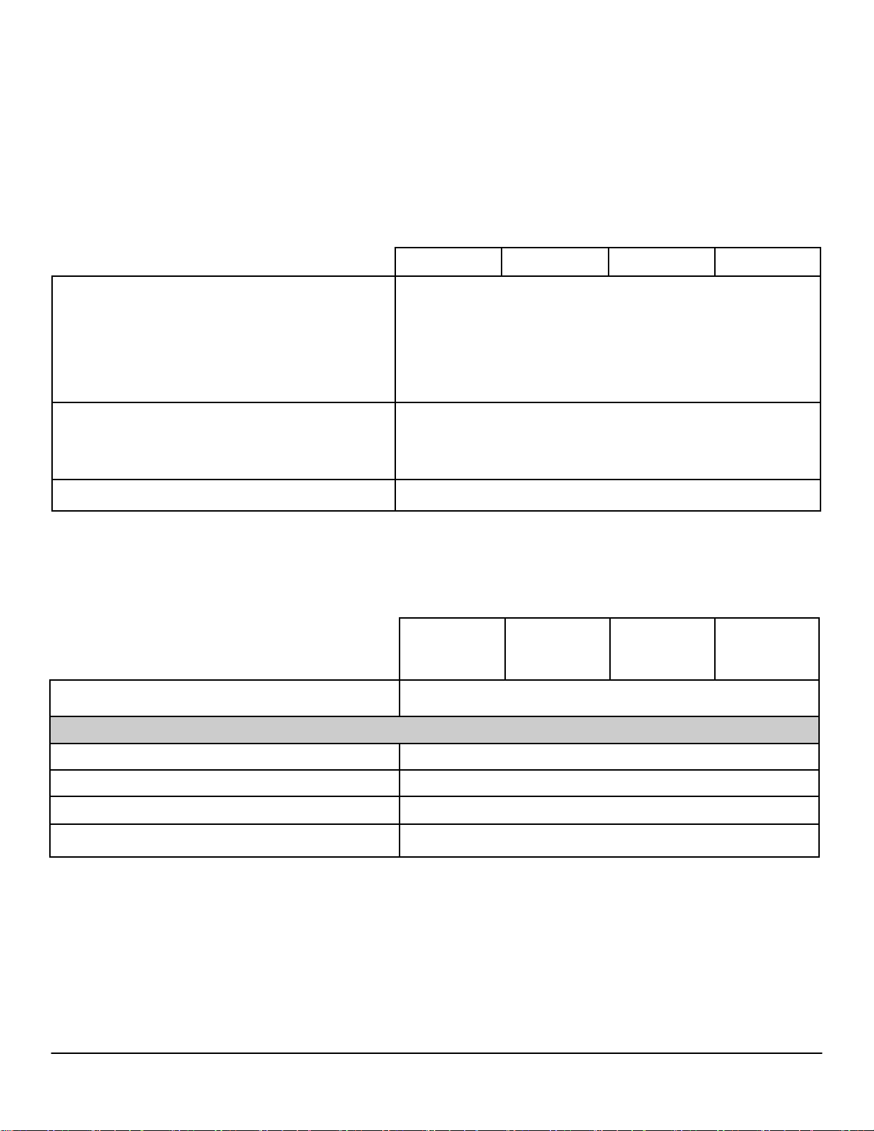
OPERATING SYSTEM
Windows Operating System
Other
OS Media Support Optional
MT DT SFF USFF
Microsoft® Windows 7® Home Basic SP1 (32 and 64 bit),
Microsoft® Windows 7® Home Premium SP1 (32 and 64 bit),
Microsoft® Windows 7® Home Premium w/MUI SP1 (32 and 64 bit),
Microsoft® Windows 7® Professional w/MUI SP1 (32 and 64 bit),
Microsoft® Windows 7® Professional SP1 (32 and 64 bit),
Microsoft® Windows 7® Ultimate SPI (32 and 64 bit),
Ubuntu (N-Series DIB) (32bit)
Ubuntu (32bit)
CHIPSET
MT DT SFF USFF
Chipset Intel Q77 Express Chipset
Non-volatile memory on chipset
BIOS Configuration SPI (Serial Peripheral Interface)
TPM 1.2 Security Device (Trusted Platform Module)1 4KB located at TPM1.2 on chipset
Non-TPM Available in select countries
NIC EEPROM
64Mbit (8MB) &32Mbit(4MB) located at SPI_FLASH on chipset
LOM configuration contained within SPI_FLASH – no dedicated
LOM EEPROM
11
Page 12
DELL™ OPTIPLEX™ 7010 TECHNICAL GUIDEBOOK VER1.2
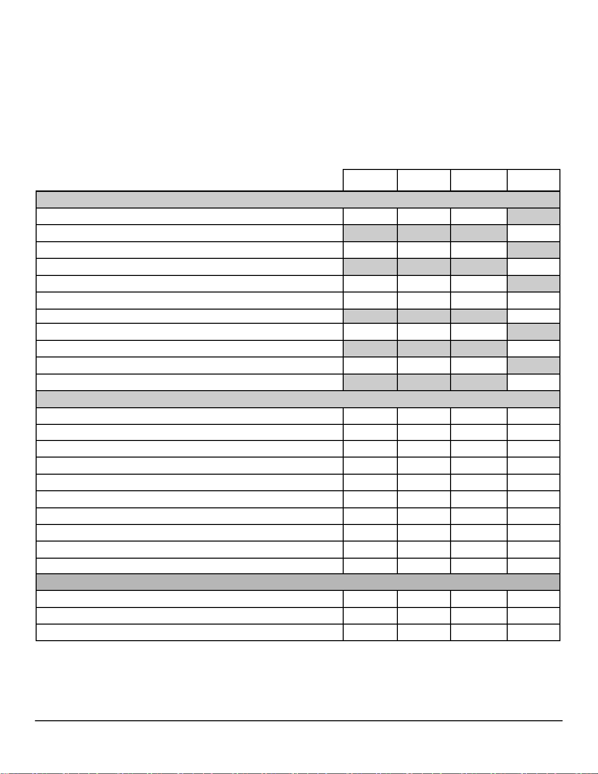
PROCESSOR
1
NOTE: Global Standard Products (GSP) are a subset of Dell’s relationship products that are managed for availability and synchronized transitions on a worldwide basis. They ensure the same platform is available for purchase globally. This allows customers to
reduce the number of configurations managed on a worldwide basis, thereby reducing their costs. They also enable companies
to implement global IT standards by locking in specific product configurations worldwide. The following GSP processors identified below will be made available to Dell customers.
NOTE: Processor numbers are not a measure of performance. Processor availability subject to change and may vary by region/
MT DT SFF USFF
Intel® Quad Core Processors
Intel® Core™ i7 3770 / 3.40GHz, 8M, VT-x, VT-d, TXT (vPro™), 77W GSP GSP GSP
Intel® Core™ i7 3770S / 3.10GHz, 8M, VT-x, VT-d, TXT (vPro™), 65W GSP
Intel® Core™ i5 3570 / 3.40GHz, 6M, VT-x, VT-d, TXT (vPro™), 77W
Intel® Core™ i5 3570S / 3.10GHz, 6M, VT-x, VT-d, TXT (vPro™), 65W
Intel® Core™ i5 3470 / 3.20GHz, 6M, VT-x, VT-d, TXT (vPro™), 77W
Intel® Core™ i5 3475S / 2.90GHz, 6M, VT-x, VT-d, TXT (vPro™), 65W
Intel® Core™ i5 3470S / 2.90GHz, 6M, VT-x, VT-d, TXT (vPro™), 65W
Intel® Core™ i5 3550 / 3.30GHz, 6M, VT-x, VT-d, TXT (vPro™), 77W
Intel® Core™ i5 3550S / 3.00GHz, 6M, VT-x, VT-d, TXT (vPro™), 65W
Intel® Core™ i5 3450 / 3.10GHz, 6M, 77W
Intel® Core™ i5 3450S / 2.80GHz, 6M, 65W
3
3
2
2
2
2
2
3
3
GSP GSP GSP
GSP
GSP GSP GSP
GSP GSP GSP GSP
GSP
X X X
X
X X X
X
Intel® Dual Core Processors
Intel® Core™ i3-3240 / 3.4GHz, 3M, VT-x, 55W2 X X X X
Intel® Core™ i3 3225, / 3.3GHz, 3M, VT-x, 55W
Intel® Core™ i3 3220, / 3.3GHz, 3M, VT-x, 55W
Intel® Core™ i3 2130 / 3.40GHz, 3M, VT-x, 65W
Intel® Core™ i3 2125 / 3.30GHz, 3M, VT-x, 65W
Intel® Core™ i3 2120 / 3.30GHz, 3M, VT-x, 65W
Intel® Core™ G860 / 3.0GHz, 3M, VT-x, 65W
Intel® Core™ G850 / 2.9GHz, 3M, VT-x, 65W
Intel® Core™ G640 / 2.8GHz, 3M, VT-x, 65W
Intel® Core™ G630 / 2.7GHz, 3M, VT-x, 65W
2
2
3
3
3
2
3
2
3
X X X X
X X X X
X X X X
X X X X
X X X X
X X X X
X X X X
X X X X
X X X X
Intel® Celeron Processors
Intel® Core™ G540 / 2.5GHz, 2M, VT-x, 65W
Intel® Core™ G530 / 2.5GHz, 2M, VT-x, 65W
2
3
X X X X
X X X X
Intel® Core™ G460 / 1.8GHz, 1.5M, VT-x, 35W X X X X
1
3rd generation CPUs natively support 3 displays with the integrated CPU graphics. 2 of the displays must be DP and connected to onboard DP
through DP cables, the other could be any other format. One of the DP port has a maximum resolution of 2500x1600 at 60Hz refresh rate and
the other DP and VGA port have max resolutions of 1920x1200 at 60Hz refresh rates. Active dongles must be used to connect non DP displays to
the 2 onboard DP ports.
2
Post launch CPU, available from June for G860, G540; July for G640, i5 3470/S, i5 3570/S, i5 3475S; September for i3 3220, i3 3225, i3 3240.
3
Available at launch, will be replaced in July or September, i5 3470/S replace i5 3450/S; i5 3570/S replace i5 3550/S; i3 3220 replace i3 2120; i3
3225 replace i3 2125;i3 3240 replace i3 2130;G860 replace G850;G640 replace G630;G540 replace G530.
12
Page 13
DELL™ OPTIPLEX™ 7010 TECHNICAL GUIDEBOOK VER1.2
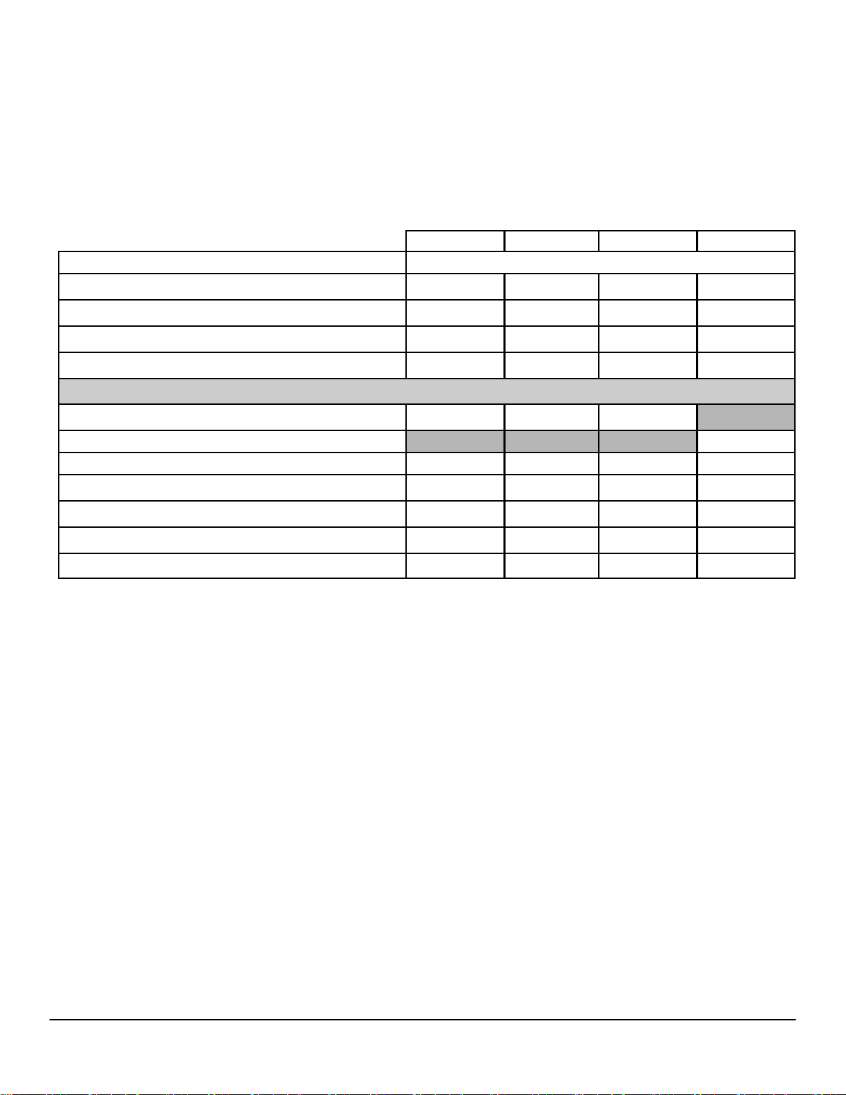
MEMORY
NOTE: Memory modules should be installed in pairs of matched memory size, speed, and technology. If the memory modules
are not installed in matched pairs, the computer will continue to operate, but with a slight reduction in performance. The entire
16GB memory range is available to 64-bit operating systems.
Type: DDR3 Synch DRAM Non-ECC Memory 1600MHz
MT DT SFF USFF
2
DIMM Slots 4 4 4 2
DIMM Capacities Up to 8GB Up to 8GB Up to 8GB Up to 8GB
Minimum Memory 2GB 2GB 2GB 2GB
1
Maximum System Memory 16GB
16GB1 16GB1 16GB1
Memory configurations
1
16GB
DDR3, 1600MHz2, (4 x 4GB) X X X
16GB1 DDR3, 1600MHz2, (2 x 8GB) X
1
8GB
DDR3, 1600 MHz2, (2 x 4GB) X X X X
6GB1 DDR3, 1600MHz2, ( 2GB + 4GB) X X X X
1
DDR3, 1600 MHz2, (2 x 2GB) X X X X
4GB
1
DDR3, 1600MHz2, (1 DIMM) X X X X
4GB
2GB DDR3, 1600MHz2, (1 DIMM) X X X X
1
To fully utilize 4GB or more of memory requires a 64-bit enabled processor and 64-bit operating system. With 32-bit OS, the total amount of
available memory will be less than 4GB. The amount less depends on the actual system configuration.
2
1600MHz memory will only perform as 1600MHz memory when 3rd generation CPUs are used. It will perform as 1333MHz memory if 2nd
generation i3 2130, i3 2125, i3 2120, G860, G850 CPUs are installed in the system. It will perform as 1066MHz memory if 2nd generation G640,
G630, G540, G530, G460 CPUs are installed in the system.
13
Page 14

DELL™ OPTIPLEX™ 7010 TECHNICAL GUIDEBOOK VER1.2
DRIVES AND REMOVABLE STORAGE
MT DT SFF USFF
Bays:
5.25-inch Optical Bay Supported (External) 2 1 1 1
Optical Drives Supported (maximum) 2 1 1 (slim-line) 1 (slim-line)
Hard Drive Bay Supported (Internal) 2 1 1 1
Hard Drives Supported 3.5”/2.5” (maximum) 2/2 1/2 1/2 0/1
Interface:
SATA 2.0 2 1 1 0
SATA 3.0 2 2 2 2
3.5” Hard Drives:
1
SATA 7200 RPM HDD X X X
1TB
1
500GB
250GB
SATA 7200 RPM HDD X X X
1
SATA 7200 RPM HDD X X X
2.5” Hard Drives:
500GB1 SATA 7200 RPM HDD X X X X
320GB1 SATA 7200 RPM HDD X X X X
320GB1 SATA 7200 RPM OPAL SED w/FIPS HDD X X X X
500GB1 SATA 7200 RPM Hybrid HDD X X X X
128GB1 SATA Solid State drive X X X X
Optical Drive: (SFF/USFF require slim-line optical drive)
DVD+/-RW
2
SATA X X X X
DVD-ROM3 SATA X X X X
Media Card Reader:
Dell 19 in 1 Media Card Reader
1
For hard drives, GB means 1 billion bytes; actual capacity varies with preloaded material and operating environment and will be less.
2
Discs burned with this drive may not be compatible with some existing drives and players; using DVD+R media provides maximum compatibility.
3
DVD-ROM drives may have write-capable hardware that has been disabled via firmware modifications.
4
Dell 19 in 1 Media Card Reader (MCR) is supported via a F5 to F3 bay converter on the MT and DT and requires a slim line optical drive.
4
X X
14
Page 15
DELL™ OPTIPLEX™ 7010 TECHNICAL GUIDEBOOK VER1.2
SYSTEM BOARD CONNECTORS
NOTE: See Detailed Engineering Specifications for maximum card dimensions.
PCI Slot(s)
1
1 1
MT DT SFF USFF
PCIe x16 Slot(s) 2 1 1 1
PCIe x16 (wired x4)Slot(s)
3
PCIe x1 Slot(s)
1 1
miniPCIe connector(s)
4
Serial ATA (SATA)
4 3 3 2
3
1 1 1
3
1
1
PCI Slots (Support Standard Rev 2.3)
2
PCIe x16 Slots (Support Standard Rev 3.0)
3
PCIe x16 (wired x 4), PCIe x1 Slots, miniPCIe (Support Standard Rev 2.0)
4
Serial ATA ( 2 ports Support Standard Rev 3.0, the rest of ports Support Standard Rev 2.0)
15
Page 16

DELL™ OPTIPLEX™ 7010 TECHNICAL GUIDEBOOK VER1.2
GRAPHICS/VIDEO CONTROLLER
NOTE: MT supports full height (FH) cards and DT and SFF supports low profi le (LP) cards.
Integrated Intel® HD Graphics 2500/4000 (3
i3/i5/i7 CPUs);
Integrated Intel® HD Graphics 2000/3000 (2nd generation Core
i3 CPUs);
Integrated Intel® HD Graphics (Pentium® Dual Core /
Celeron® CPU);
Enhanced Graphic/Video Options
1GB AMD RADEON HD 7570 Optional card
1GB AMD RADEON HD 7470 Optional card
rd
generation Core
MT DT SFF USFF
Integrated on CPU
EXTERNAL PORTS/CONNECTORS
MT DT SFF USFF
USB 2.0 (Front/Rear/Internal) 2/4/2
USB 3.0 (Front/Rear/Internal)
Serial 1 Rear
Network Connector (RJ-45) 1 Rear
PS/2 2 Rear
1394 Controller via optional PCI card
Video:
VGA
DisplayPort 2 Rear
Audio:
Line in for microphone 1 Front
Line in for microphone or stereo 1 Rear
Line out for headphones or speakers 1 Front, 1 Rear
2/2/0
Optional FH
card
2/4/2 2/4/0
2/2/0 2/2/0 2/2/0
Optional LP
card
1 Rear
0/2/0
16
Page 17

DELL™ OPTIPLEX™ 7010 TECHNICAL GUIDEBOOK VER1.2
COMMUNICATIONS - NETWORK ADAPTER (NIC)
NOTE: MT supports full height (FH) cards and DT and SFF supports low profi le (LP) cards.
Intel® 82579LM Gigabit1 Ethernet LAN 10/100/1000 (Remote
Wake Up, PXE support and Intel Active Management Technology support)
Broadcom NetXtreme 10/100/1000 PCIe Gigabit Networking
Card
1
This term does not connote an actual operating speed of 1 Gb/sec. For high speed transmission, connection to a Gigabit Ethernet server and
network infrastructure is required.
MT DT SFF USFF
Integrated on system board
Optional card
COMMUNICATIONS – WIRELESS
NOTE: MT supports full height (FH) cards and DT and SFF supports low profi le (LP) cards.
Dell Wireless 1530 PCIe WLAN card (802.11n) Optional card
Dell Wireless 1530 half miniPCIe WLAN card (802.11n)
MT DT SFF USFF
Optional
AUDIO AND SPEAKERS
Realtek ALC269Q High Definition Audio Codec Integrated on system board
Dell AX210 USB Stereo speakers Optional
Dell AX510/AX510PA Flat Panel Soundbar Speakers Optional
MT DT SFF USFF
KEYBOARD AND MOUSE
Dell USB Entry Keyboard with optional palmrest Optional
Dell Multimedia Pro Keyboard Optional
Dell Smart Card Keyboard Optional
Dell USB Optical Mouse Optional
Dell Laser Mouse Optional
MT DT SFF USFF
17
Page 18

DELL™ OPTIPLEX™ 7010 TECHNICAL GUIDEBOOK VER1.2
SECURITY
Trusted Platform Module (TPM) 1.21 Integrated on system board
Chassis Intrusion Switch Optional
Dell Smartcard Keyboard Optional
Chassis lock slot and loop support Standard
Dell Data Protection | Hardware Encryption Engine Optional
1
TPM is not available in all countries. Depending on your country regulations, no-TPM system boards may be available.
MT DT SFF USFF
SOFTWARE
Dell Client Manager Available via Dell.com
Dell Data Protection | Access (DDPA) Standard
Dell Data Protection | Encryption (DDPE) Optional
MT DT SFF USFF
ENVIRONMENTAL
NOTE: For more details on Dell Environmental features, please to go to Environmental Attributes section. See
your specifi c region for availability.
Sustainable packaging X X X
MultiPack packaging Optional, US only
Energy Ecient Power Supply Optional Standard
MT DT SFF USFF
ALL-IN-ONE STANDS AND MOUNTS
Small Form Factor AIO Stand
Ultra Small Form Factor AIO Stand
Ultra Small Form Factor Wall Mount / Desk Mount
MT DT SFF USFF
Optional
Optional
Optional
SERVICE AND SUPPORT
NOTE: For more details on Dell Service Plans please to go to: www.dell.com/service/service_plans
3 Year Warranty1 Next Business Day On-site2 (3-3-3) Standard
ProSupport Optional
1
For a copy of our guarantees or limited warranties, please write Dell USA L.P., Attn: Warranties, One Dell Way, Round Rock, TX 78682. For more
information, visit www.dell.com/warranty.
2
Service may be provided by third-party. Technician will be dispatched if necessary following phone-based troubleshooting. Subject to parts
availability, geographical restrictions and terms of service contract. Service timing dependent upon time of day call placed to Dell. U.S. only.
MT DT SFF USFF
18
Page 19

DELL™ OPTIPLEX™ 7010 TECHNICAL GUIDEBOOK VER1.2
DETAILED ENGINEERING SPECIFICATIONS
SYSTEM DIMENSIONS (PHYSICAL)
NOTE: System Weight and Shipping Weight is based on a typical confi guration and may vary based on PC
confi guration. A typical confi guration includes: integrated graphics, one hard drive, one optical drive.
Chassis Volume (liters) 26.27 15.06 8.38 3.70
Chassis Weight (pounds/kilograms)
20.68 / 9.4 17.38 / 7.9 13.2 / 6.0 7.26 / 3.3
MT DT SFF USFF
Chassis Dimensions: (HxWxD)
Height (inches/centimeters) 14.17 / 36 14.17 / 36 11.42 / 29 9.32 / 23.67
Width (inches/centimeters)
Depth (inches/centimeters)
Shipping Weight (pounds/kilograms - includes packaging materials)
6.89 / 17.5 4.02 / 10.2 3.65 / 9.26 2.56 / 6.5
16.42 / 41.7 16.14 / 41 12.28/31.2 9.44 / 24
24.57 / 11.17 20.75 / 9.43 15.82/7.19 9.63 /4.375
Packaging Parameters (HxWxD)
Height (inches/centimeters)
Width (inches/centimeters)
Depth (inches/centimeters)
14.09 / 35.79 10.84/27.53 10.19/25.88 9.63/24.46
21.31/54.13 21.31 / 54.13 19.25/48.90 19.13/48.59
18.75/47.63 18.75/47.63 15.81/40.16 14.38/36.53
SYSTEM BOARD CONNECTOR MAXIMUM ALLOWABLE DIMENSIONS
PCI Slot (Voltage supported 3.3V/5V/12V/-12V) 1 1
MT DT SFF USFF
Height (inches/centimeters) 4.376 / 11.115 2.731 /6.89
Length (inches/centimeters) 6.6 / 16.765 6.6/16.765
Maximum Wattage 25W 25W
PCIex16 Slot (BLUE) (Voltage supported 3.3V/12V) 1 1 1
Height (inches/centimeters) 4.376 / 11.115 2.731 /6.89 2.731 /6.89
Length (inches/centimeters) 6.6/ 16.765 6.6 /16.765 6.6 /16.765
Maximum Wattage 75W 50W 50W
PCIex16 wired as x4 Slot (BLACK) (Voltage supported 3.3/12V) 1 1 1
Height (inches/centimeters) 4.376 / 11.115 2.731 /6.89 2.731 /6.89
Length (inches/centimeters) 6.6 / 16.765 6.6 /16.765 6.6/16.765
Maximum Wattage 25W 25W 25W
PCIe x1 Slot (Voltage supported 3.3V/12V) 1 1
Height (inches/centimeters) 4.376 / 11.115 2.731 / 6.89
Length (inches/centimeters) 4.5 / 11.44 4.5 / 11.44
Maximum Wattage 10W 10W
Mini PCIe x1 Slot
1
19
Page 20

DELL™ OPTIPLEX™ 7010 TECHNICAL GUIDEBOOK VER1.2
SYSTEM LEVEL ENVIRONMENTAL AND OPERATING CONDITIONS
Temperature
Operating 10°C to 35°C (50°F to 95°F)
Non-Operating (Storage) -40°C to 65°C (-40°F to 149°F)
Relative Humidity 20% to 80% (non-condensing)
Maximum vibration
Operating 0.25 G at 3 to 200 Hz at 0.5 octave/min
Non-Operating 0.5 G at 3 to 200 Hz at 1 octave/min
Maximum Shock
Operating
Non-Operating
Maximum Altitude
Operating –15.2 to 3048 m (–50 to 10,000 ft)
Non-Operating –15.2 to 10,668 m (–50 to 35,000 ft)
MT DT SFF USFF
Bottom half-sine pulse with a change in velocity
of 50.8 cm/sec (20 inches/sec)
27-G faired square wave with a velocity change
of 508 cm/sec (200 inches/sec)
20
Page 21

DELL™ OPTIPLEX™ 7010 TECHNICAL GUIDEBOOK VER1.2
POWER
NOTE: These form factors utilize a more e cient Active Power Factor Correction (APFC) power supply. Dell
recommends only Universal Power Supplies (UPS) based on Sine Wave output for APFC PSUs, not an approximation of a Sine Wave, Square Wave, or quasi-Square Wave. If you have questions, please contact the manufac-
Power Supply Wattage 275W
AC input Voltage
Range
APFC EPA
90 –
264Vac
MT
275W High
Eciency
90 –
264Vac
250W
90 –
264Vac
DT
APFC EPA
250W High
Eciency
90 –
264Vac
APFC EPA
240W
90 –
264Vac
SFF
240W High
Eciency
90 –
264Vac
USFF
EPA
200W High
Eciency
90 – 264Vac
AC input current (low
ac range/high AC
5.0A / 2.5A 5.0A / 2.5A 4.4A / 2.2A 4.4A / 2.2A 4.0A / 2.0A 3.6A / 1.8A 2.9A / 1.45A
range)
AC input Frequency 47HZ/63HZ 47HZ/63HZ 47HZ/63HZ 47HZ/63HZ 47HZ/63HZ 47HZ/63HZ 47 – 63 Hz
AC holdup time (80%
load)
Minimum Eciency
(Energy Star 5.2 Compliant)
Typical Eciency
(Active PFC)
16 mini sec 16 mini sec 16 mini sec 16 mini sec 16 mini sec 16 mini sec 16 mini sec
65%
87 – 90 –
87% @ 20
– 50 –
100% load
65% 65% N/A
87 – 90 –
87% @ 20
– 50 –
100% load
87 – 90 –
87% @ 20
– 50 –
100% load
87 – 90 –
87% @ 20 –
50 – 100%
load
DC parameters
+3.3V output 10.0A 10.0A 7.0 A 7.0 A 3.5A 3.5A
+5.0V output 13A 13A 15A 15A 11A 11A
N/A
N/A
+12VA -
12.5 A &
+12VB - 6.0
+12.0V output
12VA/17A;
12VB/10A
12VA/17A;
12VB/10A
17.8A 17.8A 17A 17A
A
Note: +12VB
Rated at
0.4A when in
Standby
Mode.
+5.0V auxiliary output 4.0A 4.0A 4.0 4.0 4.0A 4.0A
-12.0V output 0.5A 0.5A 0.5A 0.5A 0.5A 0.5A
Max total power 275W 275W 250W 250W 240W 240W
Max combined +3.3V /
+5.0V power
100W 100W 90W 90W 60W 60W
N/A
0.1 A
200W
N/A
Max combined 12.0V
power (note: only if
240W 240W
N/A N/A N/A N/A 200W
more than one 12V rail)
BTUs/h (based on PSU
max wattage)
938 BTU 938 BTU 853 BTU 853 BTU 819 BTU 819 BTU
Power Supply Fan 80*25mm 80*25mm
80*20/25mm 80*20/25m
m
60*25mm 60*25mm N/A
682 BTU
Compliance:
Erp Lot6 Tier 2 0.5watt
requirement
Yes Yes Yes Yes Yes Yes Yes
Blue Angel Compliant Yes Yes Yes Yes Yes Yes Yes
Climate Savers /
80Plus Compliant
FEMP Standby Power
Compliant
No Yes No Yes No Yes Yes
Yes Yes Yes Yes Yes Yes Yes
CECP Compliant No Yes No Yes No Yes Yes
21
Page 22

DELL™ OPTIPLEX™ 7010 TECHNICAL GUIDEBOOK VER1.2
POWER
NOTE: These form factors utilize a more ecient Active Power Factor Correction (APFC) power supply. Dell recommends only Uninterruptible Power Supplies (UPS) based on Sine Wave output for APFC
PSUs, not an approximation of a Sine Wave, Square Wave, or quasi-Square Wave. If you have ques-
tions, please contact the manufacture to confirm the output type.
3.0v CMOS battery (Type and estimated battery life)
Brand Type Voltage Composition Life
PANASONIC CR-2032L/
BE
MITSUBISHI CR2032 3V Lithium Continuous Discharge Under 15 kΩ Load to 2.0V End-
3V Lithium Continuous Discharge Under 15 kΩ Load to 2.5V End-
Voltage.
20°C ±2°C: 1183Hrs. or Longer, 1133Hrs.or Longer after 12
months.
Voltage.
20°C±2°C: 1000Hrs. or Longer, 970Hrs.or Longer after 12
months.
0°C±2°C: 910Hrs. or Longer, 890Hrs.or Longer after 12
months.
22
Page 23

DELL™ OPTIPLEX™ 7010 TECHNICAL GUIDEBOOK VER1.2
AUDIO
INTEGRATED REALTEK ALC269Q HIGH DEFINITION AUDIO
High Definition Stereo support X X X X
Number of channels 2
Number of Bits / Audio resolution 16, 20, and 24-bit resolution
Sampling rate (recording/playback) Support 44.1K/48K/96K/192 kHz sample rates
Signal to Noise Ratio 98 dB DAC outputs, 90 dB for ADC inputs
Analog Audio X X X X
Dolby Digital
THX
Digital out (S/PDIF)
Audio Jack Impedance
Microphone 40K ohm~60K ohm
Line-In 40K ohm~60K ohm
Line-Out 100~150 ohm
Headphone 1~4 ohm
Internal Speaker Power Rating 2Watt (peak) / 1Watt (average)
MT DT SFF USFF
COMMUNICATIONS - INTEGRATED LAN
INTEGRATED INTEL® 82579 GIGABIT1
ETHERNET LAN 10/100/1000
External Connector Type RJ45
Data Rates supported 10/100/1000 Mbps
Controller Details
Controller bus architecture
Integrated memory N/A
Data transfer mode (example Bus-Master DMA) N/A
Power consumption (full operation per data rate connection speed) 711mW (Max.)
Power consumption (standby operation) 227mW (Max.)
IEEE standards compliance (example 802.1P) 802.3
Hardware Certifications (example FCC, B, GS mark…) N/A
Boot ROM Support EEPROM (located in SPI)
Network Transfer Mode (example Full Duplex, Half Duplex)
Network Transfer Rate (example 10BASE-T (half-duplex) 10 Mbps
10BASE-T (full-duplex) 20 Mbps
100BASE-TX (half-duplex) 100 Mbps
100BASE-TX (full-duplex) 200 Mbps
1000BASE-T (full-duplex) 2000 Mbps
MT DT SFF USFF
PCIe-based interface for S0 state, SMBus for Sx
low power state
10 Mb (full/half-duplex)
100 Mb (full/half-duplex)
1000 Mb (full-duplex)
23
Page 24

DELL™ OPTIPLEX™ 7010 TECHNICAL GUIDEBOOK VER1.2
COMMUNICATIONS - INTEGRATED LAN (CONT.)
INTEGRATED INTEL® 82579 GIGABIT1
ETHERNET LAN 10/100/1000 (CONT.)
MT DT SFF USFF
Environmental
Operating temperature 0°C to 85°C (32° F to 185° F)
Operating humidity 20% to 80% (non-condensing)
Operating System Driver Support
Windows 7 32/64, Windows XP 32/64, Vista
32/64
Manageability (examples WOL, PXE) WOL, PXE 2.1
Management Capabilities Alerting
1
This term does not connote an actual operating speed of 1 Gb/sec. For high speed transmission, connection to a Gigabit Ethernet server and
network infrastructure is required.
Intel® Standard Manageability, 3rd generation
i5/i7 processors with vPro Technology
COMMUNICATIONS – NETWORK ADAPTER (NIC)
NOTE: MT supports full height (FH) cards and DT and SFF supports low profi le (LP) cards.
BROADCOM NETXTREME 10/100/1000
PCIE GIGABIT
1
NETWORKING CARD
Connector Type RJ45
MT DT SFF USFF
Data Rates supported 10/100/1000 Mbps Half/Full duplex
Controller Details
Controller bus architecture (example PCIe 1.0a x1) PCIe c1.0a x1
Integrated memory 64KBytes RX, 8KBytes TX
Data transfer mode (example Bus-Master DMA) Bus-Master DMA
Power consumption (full operation per data rate connection speed) 2.84W (860mA @ +3.3V)
Power consumption (standby operation) Less than 300mW
IEEE standards compliance (example 802.1P) 802.3, 802.2, 802.3x, 802.1p
Hardware Certifications (example FCC, B, GS mark…) FCC B, VCCI B, CE
Boot ROM Support No
Network Transfer Mode (example Full Duplex, Half Duplex)
Network Transfer Rate (example 10BASE-T (half-duplex) 10 Mbps
10BASE-T (full-duplex) 20 Mbps
100BASE-TX (half-duplex) 100 Mbps
100BASE-TX (full-duplex) 200 Mbps
1000BASE-T (full-duplex) 2000 Mbps
1
This term does not connote an actual operating speed of 1 Gb/sec. For high speed transmission, connection to a Gigabit Ethernet server and
network infrastructure is required.
10BASE-T (full-duplex) 20 Mbps Max*
100BASE-TX (half-duplex) 100 Mbps Max*
100BASE-TX (full-duplex) 200 MbpsMax*
1000BASE-T (full-duplex) 2000 Mbps Max*
* Depends on the system environment.
24
Page 25

DELL™ OPTIPLEX™ 7010 TECHNICAL GUIDEBOOK VER1.2
COMMUNICATIONS – NETWORK ADAPTER (NIC) (CONT.)
BROADCOM NETXTREME 10/100/1000
PCIE GIGABIT
Environmental
Operating temperature 0°C C to 55°C (32°F - 131°F)
Operating humidity 5% ~ 85% (non-condensing)
Operating System Driver Support
Manageability (examples WOL, PXE) WOL, PXE2.1, ACPI
Management Capabilities Alerting (example ASF 2.0) None
1
This term does not connote an actual operating speed of 1 Gb/sec. For high speed transmission, connection to a Gigabit Ethernet server and network
infrastructure is required.
1394a FIREWIRE PCI ADD-IN CARD
Connector Type
1
NETWORKING CARD (CONT.)
MT DT SFF USFF
Microsoft Client XP/Vista/Win 7 (32bit/64bit)
Linux
IEEE-1394a-2000 (6 pins)
Controller Details
Controller bus architecture (example PCIe 1.0a x1) PCI 2.3
Chipset LSI
IO Ports IEEE 1394 (FireWire) with a transfer rate of up to 400Mbps
Power Consumption Under 30 mA
Connector 2 IEEE-1394a 6 pins connectors
OS Support Microsoft Client XP/Vista/Win 7 (32bit/64bit)
25
Page 26

DELL™ OPTIPLEX™ 7010 TECHNICAL GUIDEBOOK VER1.2
COMMUNICATIONS – WIRELESS
DELL WIRELESS 1530 PCIE WLAN CARD (802.11N)
Dell Wireless 1530 PCIe WLAN card (802.11n) Custom WLAN Antenna
Dell Wireless 1530 half miniPCIe WLAN card (802.11n)
MT DT SFF USFF
Custom WLAN
Antenna
Controller Details
Controller bus architecture
WLAN standards supported 802.11a, 802.11b, 802.11g, 802.11n
802.11b Data Rates supported 11, 5.5, 2, 1 Mbps
802.11a Data Rates supported 54, 48, 36, 24, 18, 12, 9, 6 Mbps
802.11g Data Rates supported 54, 48, 36, 24, 18, 12, 11, 9, 6, 5.5, 2, 1 Mbps
802.11n Data Rates supported
Encryption
Operating temperature 0°C –70°C
Electrically compatible with the PCI Express Base Specification
v1.1 (x1 lane) and PCIe v1.0a.
270, 240, 180, 135, 130, 121.5, 120, 117, 108, 104, 90, 81, 78,
65, 60, 58.5, 54, 52, 40.5, 39, 30, 27, 26, 19.5, 13.5, 13, 6.5
Mbps
WEP 64-bit and 128-bit,
TKIP, AES-CCMP 128-bit
Operating humidity Max Operating Humidity 85 %
Operating System Driver Support Microsoft Client XP/Vista/Win 7 (32bit/64bit)
26
Page 27

DELL™ OPTIPLEX™ 7010 TECHNICAL GUIDEBOOK VER1.2
COMMUNICATIONS – SERIAL / PARALLEL PORT PCIE ADD-IN CARD
NOTE: MT supports full height (FH) cards and DT and SFF supports low profi le (LP) cards.
SERIAL / PARALLEL PORT PCIE ADD-IN CARD
Connector Type RS-232 and IEEE1284
Data Rates supported
MT DT SFF USFF
50bps ~115.2Kbps(Serial)&Maximum 1.8MBp(Parallel)
Controller Details
Controller bus architecture (example PCIe 1.0a x1) PCI Express one lane (x1)
Microsoft Client XP/Vista/ Win 7 (32bit/64bit)
Driver Support
Full height Serial / Parallel add-in card
Optional
Environment
Operation Temperature 0°C to 60°C (32°F to 140°F)
Operation Humidity 5 to 95% RH
Storage Temperature -20°C to 85°C (-4°F to 185°F)
Linux
DOS
COMMUNICATIONS – SERIAL PORT PCIE ADD-IN CARD
NOTE: MT supports full height (FH) cards and DT and SFF supports low profi le (LP) cards.
SERIAL PORT PCIE ADD-IN CARD
Connector Type RS-232
Data Rates supported 50bps ~115.2Kbps
MT DT SFF USFF
Controller Details
Controller bus architecture (example PCIe 1.0a x1) PCI Express one lane (x1)
Microsoft Client XP/Vista/Win 7 (32bit/64bit)
Driver Support
Half height Serial add-in card
Environment
Operation Temperature 0°C to 60°C (32°F to 140°F)
Operation Humidity 5 to 95% RH
Storage Temperature -20°C to 85°C (-4°F to 185°F)
Linux
DOS
Optional
27
Page 28

DELL™ OPTIPLEX™ 7010 TECHNICAL GUIDEBOOK VER1.2
COMMUNICATIONS – SERIAL / PARALLEL PORT PCIE ADD-IN CARD
NOTE: MT supports full height (FH) cards and DT and SFF supports low profi le (LP) cards.
PARALLEL PORT PCIE ADD-IN CARD
Connector Type IEEE1284
Data Rates supported
MT DT SFF USFF
Maximum 1.8MBp
Controller Details
Controller bus architecture (example PCIe 1.0a x1) PCI Express one lane (x1)
Microsoft Client XP/Vista/7 (32bit/64bit)
Driver Support
Half height
parallel add-in card
Environment
Operation Temperature 0°C to 60°C (32°F to 140°F)
Operation Humidity 5 to 95% RH
Storage Temperature -20°C to 85°C (-4°F to 185°F)
Linux
DOS
Optional
28
Page 29

DELL™ OPTIPLEX™ 7010 TECHNICAL GUIDEBOOK VER1.2
GRAPHICS/VIDEO CONTROLLER
NOTE: MT supports full height (FH) cards and DT and SFF supports low profi le (LP) cards.
Onboard Graphics
1,2,3,4
Integrated Intel® HD Graphics 2500/4000 (3rd generation Core i3/i5/i7
CPUs);
MT DT SFF USFF
Integrated Intel® HD Graphics 2000/3000 (2nd generation Core i3 CPUs);
Integrated Intel® HD Graphics (Pentium® Dual Core CPU);
Bus Type
Integrated
Gen6 Core Intel® HD Graphics /HD Graphics
GPU core clock
Gen7 Core Intel® HD Graphics 2500 / 4000 @
2000 @ 850MHz
650MHz
Frame Buer Memory (onboard and shared) Size and Speed
Depends on available system memory (Up to
1.7GB with 4GB system Memory)
Overlay Planes Yes
Maximum Color Depth 32 bit
Maximum Vertical Refresh Rate 75 Hz
Multiple Display Support Yes
Operating Systems Graphics/ Video API Support OpenGL 3.1/OpenCLv1.1 /DirectX 11
Supported Resolutions and Max Refresh Rates (Hz) (Note: Analog and/or
digital)
Up to 2560x1600 @ 60Hz (DP)
Up to 1920x1200 @ 60Hz (VGA only)
External Connectors VGA, 2 DisplayPort
DisplayPort
Bus Type DDPC
DisplayPort Audio Support Yes
VGA
Bus Type CRT
VGA Audio Support No
1
Up to 1.7 GB of system memory may be allocated to support integrated graphics, depending on operating system, system memory size and other
factors.
2
3rd generation CPUs natively support 3 displays with the integrated CPU graphics. Three simultaneous display output requires one DP port with a
maximum resolution of 2500x1600 at 60Hz refresh rate and a DP and VGA port with max resolutions of 1920x1200 at 60Hz refresh rates.
3
Display output from both onboard and discrete simultaneously if multi display option in BIOS is enabled and OS used is Win7.
4
For dual graphics card configuration in PCIex16 and PCIex16 (wire as 4), Bios will disable multi display option automatically and display output
only from graphics cards.
29
Page 30

DELL™ OPTIPLEX™ 7010 TECHNICAL GUIDEBOOK VER1.2
1GB AMD RADEON™ HD7570
Bus Type (example integrated or PCIe x16) PCIEx16
GPU core clock 650Mhz
Frame Buer Memory (onboard and shared) Size and Speed 800Mhz
Maximum power consumption 50W
Overlay Planes Yes
Maximum Color Depth 32-bit
Maximum Vertical Refresh Rate 200Hz
Multiple Display Support Yes
Operating Systems Graphics/ Video API Support D3D/OpenGL 4.1/OpenCLv1.1/DirectX11
Supported Resolutions and Max Refresh Rates (Hz) (Note: Analog and/or digital)
External connectors DisplayPort, DVI-I
Audio Support
Dimensions of full height card inches/centimeters (L x H)
Dimensions of low profile card inches/centimeters (L x H)
Environmental Operating Conditions (Non-Condensing):
Operating Temperature Range 10°C -55°C
MT DT SFF
Dual-Link DVI: 2560 x 1600, 32-bit color
DisplayPort: 2560 x 1600, 32-bit color
Yes (For native DP). Able to support audio for DP to
HDMI dongle that support audio pass through.
6.6 x 4.7 /
16.764 x 12.0
6.6 x 3.35 / 16.764 x 8.5
Relative Humidity Range 5-90% RH
Altitude Range 0-20,000 ft.
1GB AMD RADEON™ HD7470
Bus Type (example integrated or PCIe x16) PCIEx16
GPU core clock 775Mhz
Frame Buer Memory (onboard and shared) Size and Speed 900Mhz
Maximum power consumption 25W
Overlay Planes Yes
Maximum Color Depth 32-bit
Maximum Vertical Refresh Rate 200Hz
Multiple Display Support Yes
Operating Systems Graphics/ Video API Support D3D/OpenGL 4.1/OpenCLv1.1/DirectX11
Supported Resolutions and Max Refresh Rates (Hz) (Note: Analog and/or digital)
External connectors DisplayPort, DVI-I
Audio Support
Dimensions of full height card inches/centimeters (L x H)
Dimensions of low profile card inches/centimeters (L x H)
Environmental Operating Conditions (Non-Condensing):
MT DT SFF
Dual-Link DVI: 2560 x 1600, 32-bit color
DisplayPort: 2560 x 1600, 32-bit color
Yes (For native DP). Able to support audio for DP to
HDMI dongle that support audio pass through.
6.6 x 4.7 /
16.764 x 12.0
6.6 x 3.35 / 16.764 x 8.5
Operating Temperature Range 10°C -55°C
Relative Humidity Range 5-90% RH
Altitude Range 0-20,000 ft.
30
Page 31

DELL™ OPTIPLEX™ 7010 TECHNICAL GUIDEBOOK VER1.2
HARD DRIVES1
3.5” 1TB SATA 7200 RPM HDD
Capacity 1TB
Dimensions inches (W x D x H) Approximately (4.00 x 5.787 x 1.028 inches)
Interface type and Maximum speed Up to 6Gb/s (SATA 3.0)
Internal buer size 32 MB
Rotational Speed 7200 rpm
Logical Blocks 1,953,525,168
Power Source
Power Consumption (reference only) Idle 5.0W, Active 10.0W(running IOmeter utility)
Spin Up Current (reference only) 5V (1A) ,12V (2A)
Environmental Operating Conditions (Non-Condensing):
Temperature Range 5°C to 60°C
Relative Humidity Range 20% to 80% non-condensing
Maximum Wet Bulb Temperature 29°C
Altitude Range -50 ft to 10000 ft
Environmental Non-Operating Conditions (Non-Condensing):
Temperature Range -40°C to 65°C
Relative Humidity Range 10% to 90% non-condensing
Maximum Wet Bulb Temperature 38°C
Altitude Range -50 ft to 35000 ft
1
For hard drives, GB means 1 billion bytes ; actual capacity varies with preloaded material and operating environment and will be less.
31
Page 32

DELL™ OPTIPLEX™ 7010 TECHNICAL GUIDEBOOK VER1.2
HARD DRIVES1 (CONT.)
3.5” 500GB SATA 7200 RPM HDD
Capacity 500GB
Dimensions inches (W x D x H) Approximately (4.00 x 5.787 x 1.028 inches)
Interface type and Maximum speed Up to 6Gb/s (SATA 3.0)
Internal buer size 16 MB
Rotational Speed 7200 rpm
Logical Blocks 976,773,168
Power Source
Power Consumption (reference only) Idle 5.0W, Active 10.0W(running IOmeter utility)
Spin Up Current (reference only) 5V (1A) ,12V (2A)
Environmental Operating Conditions (Non-Condensing):
Temperature Range 5°C to 60°C
Relative Humidity Range 20% to 80% non-condensing
Maximum Wet Bulb Temperature 29°C
Altitude Range -50 ft to 10000 ft
Environmental Non-Operating Conditions (Non-Condensing):
Temperature Range -40°C to 65°C
Relative Humidity Range 10% to 90% non-condensing
Maximum Wet Bulb Temperature 38°C
Altitude Range -50 ft to 35000 ft
1
For hard drives, GB means 1 billion bytes ; actual capacity varies with preloaded material and operating environment and will be less.
32
Page 33

DELL™ OPTIPLEX™ 7010 TECHNICAL GUIDEBOOK VER1.2
HARD DRIVES1 (CONT.)
3.5” 250GB SATA 7200 RPM HDD
Capacity 250GB
Dimensions inches (W x D x H) Approximately (4.00 x 5.787 x 1.028 inches)
Interface type and Maximum speed Up to 6Gb/s (SATA 3.0)
Internal buer size 8 MB
Rotational Speed 7200 rpm
Logical Blocks 488,397,168
Power Source
Power Consumption (reference only) Idle 5.0W, Active 10.0W(running IOmeter utility)
Spin Up Current (reference only) 5V (1A) ,12V (2A)
Environmental Operating Conditions (Non-Condensing):
Temperature Range 5°C to 60°C
Relative Humidity Range 20% to 80% non-condensing
Maximum Wet Bulb Temperature 29°C
Altitude Range -50 ft to 10000 ft
Environmental Non-Operating Conditions (Non-Condensing):
Temperature Range -40°C to 65°C
Relative Humidity Range 10% to 90% non-condensing
Maximum Wet Bulb Temperature 38°C
Altitude Range -50 ft to 35000 ft
1
For hard drives, GB means 1 billion bytes ; actual capacity varies with preloaded material and operating environment and will be less.
33
Page 34

DELL™ OPTIPLEX™ 7010 TECHNICAL GUIDEBOOK VER1.2
HARD DRIVES1 (CONT.)
2.5” 500GB SATA 7200 RPM HDD
Capacity
Dimensions inches (W x D x H)
Interface type and Maximum speed
Internal buer size
Rotational Speed
Logical Blocks
Approximately (3.93 x 2.75 x 0.374 inches)
500GB
Up to 3Gb/s
16 MB
7200 rpm
976,773,168
Power Source
Power Consumption (reference only) Idle 0.7W, Active 3.25W
Spin Up Current (reference only) 5V (1A)
Environmental Operating Conditions (Non-Condensing):
Temperature Range
Relative Humidity Range
20% to 80% non-condensing
5°C to 60°C
Maximum Wet Bulb Temperature
Altitude Range
29°C
-50 ft to 10000 ft
Environmental Non-Operating Conditions (Non-Condensing):
Temperature Range
Relative Humidity Range
10% to 90% non-condensing
Maximum Wet Bulb Temperature
Altitude Range
1
For hard drives, GB means 1 billion bytes ; actual capacity varies with preloaded material and operating environment and will be less.
-40°C to 65°C
38°C
-50 ft to 35000 ft
34
Page 35

DELL™ OPTIPLEX™ 7010 TECHNICAL GUIDEBOOK VER1.2
HARD DRIVES1 (CONT.)
2.5” 320GB SATA 7200 RPM HDD
Capacity
Dimensions inches (W x D x H)
Interface type and Maximum speed
Internal buer size
Rotational Speed
Logical Blocks
Approximately (3.93 x 2.75 x 0.374 inches)
320GB
Up to 3Gb/s
16 MB
7200 rpm
625,142,448
Power Source
Power Consumption (reference only) Idle 0.7W, Active 3.25W
Spin Up Current (reference only) 5V (1A)
Environmental Operating Conditions (Non-Condensing):
Temperature Range
Relative Humidity Range
10% to 90% non-condensing
5°C to 60°C
Maximum Wet Bulb Temperature
Altitude Range
29°C
-50 ft to 10000 ft
Environmental Non-Operating Conditions (Non-Condensing):
Temperature Range
Relative Humidity Range
10% to 90% non-condensing
Maximum Wet Bulb Temperature
Altitude Range
1
For hard drives, GB means 1 billion bytes ; actual capacity varies with preloaded material and operating environment and will be less.
-40°C to 65°C
38°C
-50 ft to 35000 ft
35
Page 36

DELL™ OPTIPLEX™ 7010 TECHNICAL GUIDEBOOK VER1.2
HARD DRIVES1 (CONT.)
.
2.5” 320GB SATA 7200 RPM OPAL SED W/FIPS HDD
Capacity 320GB
Dimensions inches (W x D x H) Approximately (2.75 x 3.94 x 0.374 inches)
Interface type and Maximum speed Up to 3Gb/s
Internal buer size 16 MB
Rotational Speed 7200 rpm
Logical Blocks 625,142,448
Power Source
Power Consumption (reference only) Idle 0.7W, Active 3.25W
Spin Up Current (reference only) 5V (1A)
Environmental Operating Conditions (Non-Condensing):
Temperature Range 5°C to 60°C
Relative Humidity Range 20% to 80% non-condensing
Maximum Wet Bulb Temperature 29°C
Altitude Range -50 ft to 10000 ft
Environmental Non-Operating Conditions (Non-Condensing):
Temperature Range -40°C to 65°C
Relative Humidity Range 10% to 90% non-condensing
Maximum Wet Bulb Temperature 38°C
Altitude Range -50 ft to 35000 ft
1
For hard drives, GB means 1 billion bytes ; actual capacity varies with preloaded material and operating environment and will be less.
36
Page 37

DELL™ OPTIPLEX™ 7010 TECHNICAL GUIDEBOOK VER1.2
HARD DRIVES1 (CONT.)
2.5” 500GB SATA 7200 RPMHYBRID HDD
Capacity
Dimensions inches (W x D x H)
Interface type and Maximum speed
Internal buer size
Approximately (3.93 x 2.75 x 0.374 inches)
500GB
Up to 6Gb/s
16 MB
Flash Cache 8GB
Logical Blocks
976,773,168
Power Source
Power Consumption (reference only) Idle 0.8W, Active 3.25W
Spin Up Current (reference only) 5V (1A)
Environmental Operating Conditions (Non-Condensing):
Temperature Range
Relative Humidity Range
20% to 80% non-condensing
5°C to 60°C
Maximum Wet Bulb Temperature
Altitude Range
29°C
-50 ft to 10000 ft
Environmental Non-Operating Conditions (Non-Condensing):
Temperature Range
Relative Humidity Range
10% to 90% non-condensing
Maximum Wet Bulb Temperature
Altitude Range
1
For hard drives, GB means 1 billion bytes ; actual capacity varies with preloaded material and operating environment and will be less.
-40°C to 65°C
38°C
-50 ft to 35000 ft
37
Page 38

DELL™ OPTIPLEX™ 7010 TECHNICAL GUIDEBOOK VER1.2
HARD DRIVES1 (CONT.)
2.5” 128GB1 SATA SOLID STATE DRIVE
Capacity 128GB
Dimensions inches (W x D x H)
Interface type and Maximum speed Up to 6Gb/s (SATA 3.0)
MTBF 1M hours
Logical Blocks 250,069,680
Approximately (2.75 x 3.94 x 0.276 inches)
Power Source
Power Consumption (reference only) Idle 0.5W, Active 2.5W
Environmental Operating Conditions (Non-Condensing):
Temperature Range 0°C to 70°C
Relative Humidity Range 10 to 90%
Maximum Wet Bulb Temperature 29°C
Op Shock (@0.5ms) 1,500G
Environmental Non-Operating Conditions (Non-Condensing):
Temperature Range -55°C to 95°C
Relative Humidity Range 5 to 95%
Maximum Wet Bulb Temperature 38°C
1
For hard drives, GB means 1 billion bytes ; actual capacity varies with preloaded material and operating environment and will be less.
38
Page 39

DELL™ OPTIPLEX™ 7010 TECHNICAL GUIDEBOOK VER1.2
OPTICAL DRIVES
DVD +/- RW1
External Dimensions
inches/centimeters
(Without Bezel – W x H x
D)
Weight (max) pounds/
kilograms
Interface type and speed SATA 1.5Gbit/s SATA 1.5Gbit/s SATA 1.5Gbit/s SATA 1.5Gbit/s
Disc Capacity Standard Standard Standard Standard
Internal buer size supplier dependent supplier dependent supplier dependent supplier dependent
Access Times (typical) supplier dependent supplier dependent supplier dependent supplier dependent
Maximum Data Transfer Rates
Writes 16x DVD/48x CD 16x DVD/48x CD 8x DVD/ 24x CD 8x DVD / 24x CD
Reads 16x DVD/48x CD 16x DVD/48x CD 8x DVD/ 24x CD 8x DVD/ 24x CD
Power Source
DC Power Requirements 12V, 5V 12V, 5V 5V 5V
DC Current
Environmental Operating Conditions (Non-Condensing):
Operating Temperature
Range
Relative Humidity Range 20% to 80% RH 20% to 80% RH 20% to 80% RH 20% to 80% RH
Maximum Wet Bulb Temperature
Altitude Range -200 to 3048 -200 to 3048 -200 to 3048 -200 to 3048
Environmental Non-Operating Conditions (Non-Condensing):
Operating Temperature
Range
Relative Humidity Range 5% to 95% RH 5% to 95% RH 5% to 95% RH 5% to 95% RH
Maximum Wet Bulb Temperature
Altitude Range -200 to 10600m -200 to 10600m -200 to 10600m -200 to 10600m
1
Discs burned with this drive may not be compatible with some existing drives and players; using DVD+R media provides maximum compatibility.
148.2mm(6in)/42mm
1200mA (12V)/ 900mA
MT DT SFF USFF
(2in)/ 171 (max)
700g 700g 170g 170g
(5V)
5°C to 50°C 5°C to 50°C 5°C to 50°C 5°C to 50°C
29°C 29°C 29°C 29°C
-40°C to 65°C -40°C to 65°C -40°C to 65°C -40°C to 65°C
38°C 38°C 38°C 38°C
148.2mm(6in)/42mm
(2in)/ 171 (max)
1200mA (12V)/ 900mA
(5V)
128.0 mm (5.04)/ 12.7mm
(0.5 in)/ 126.1mm (4.97in)
1000mA 1000mA
128.0 mm (5.04)/ 12.7mm
(0.5 in)/ 126.1mm (4.97in)
DVD-ROM
External Dimensions
inches/centimeters
(Without Bezel – W x H x
D)
Weight (max) pounds/
kilograms
Interface type and speed SATA 1.5Gbit/s SATA 1.5Gbit/s SATA 1.5Gbit/s SATA 1.5Gbit/s
Disc Capacity Standard Standard Standard Standard
Internal buer size supplier dependent supplier dependent supplier dependent supplier dependent
Access Times (typical) supplier dependent supplier dependent supplier dependent supplier dependent
Maximum Data Transfer Rates
Writes N/A N/A N/A N/A
Reads 16x DVD/48x CD 16x DVD/48x CD 8x DVD/ 24x CD 8x DVD/ 24x CD
148.2mm(6in)/42mm
MT DT SFF USFF
(2in)/ 171 (max)
700g 700g 165g 165g
148.2mm(6in)/42mm
(2in)/ 171 (max)
128.0 mm (5.04)/ 12.7mm
(0.5 in)/ 126.1mm (4.97in)
128.0 mm (5.04)/ 12.7mm
(0.5 in)/ 126.1mm (4.97in)
39
Page 40

DELL™ OPTIPLEX™ 7010 TECHNICAL GUIDEBOOK VER1.2
OPTICAL DRIVES (CONT.)
DVD-ROM (CONT.)
Power Source
DC Power Requirements 12V, 5V 12V, 5V 5V 5V
DC Current
Environmental Operating Conditions (Non-Condensing):
Operating Temperature
Range
Relative Humidity Range 20% to 80% RH 20% to 80% RH 20% to 80% RH 20% to 80% RH
Maximum Wet Bulb Temperature
Altitude Range -200 to 3048m -200 to 3048m -200 to 3048m -200 to 3048m
Environmental Non-Operating Conditions (Non-Condensing):
Operating Temperature
Range
Relative Humidity Range 5% to 95% RH 5% to 95% RH 5% to 95% RH 5% to 95% RH
Maximum Wet Bulb Temperature
1200mA (12V)/ 900mA
MT DT SFF USFF
(5V)
5°C to 50°C 5°C to 50°C 5°C to 50°C 5°C to 50°C
29°C 29°C 29°C 29°C
-40°C to 65°C -40°C to 65°C -40°C to 65°C -40°C to 65°C
38°C 38°C 38°C 38°C
1200mA (12V)/ 900mA
(5V)
800mA 800mA
Altitude Range -200 to 10600m -200 to 10600m -200 to 10600m -200 to 10600m
40
Page 41

DELL™ OPTIPLEX™ 7010 TECHNICAL GUIDEBOOK VER1.2
MEDIA CARD READER (MCR)
NOTE: Dell 19 in 1 Media Card Reader (MCR) is supported via a F5 to F3 bay converter on the MT and DT and may require a slim
line optical drive depending on selectable configuration. MCR is not available on the SFF and USFF chassis.
19 IN 1 MEDIA CARD READER
External Dimensions inches/(centimeters)
(With Bezel – W x H)
Weight (max) pounds/kilograms ~155g
Interface type and speed USB 2.0, 480Mb/s
Media Supported ( maximum capacity supported will vary by Flash Media Types)
Media Supported
Support Specification Versions:
Power Source
Max Power Requirements 2.5W
Supply Voltage Range 4.75V ~ 5.25V
Power Consumption: Standby less than 0.5mA @ 5.0VDC
Environmental Operating Conditions (Non-Condensing):
Micro Secure Digital (Micro-SD)(with adapter)
Multi Media Card Micro(MMC Micro) (with adapter)
Memory Stick Micro(MS Micro)(M2) (with adapter)
Memory Stick Pro (MS-PRO) Specification 1.02
3.99/(10.13cm)/1.0/(2.54cm)
Mini Secure Digital (mini-SD)
RS Multi Media Card (RS-MMC)
Multi Media Card plus (MMC plus)
RS Multi Media Card plus (RS-MMC plus)
Memory Stick Pro(MS Pro)
Memory Stick Pro Duo (MS Pro Duo)
Memory Stick Duo (MS-Duo)
Compact Flash type I/II Version 4.0
Smart Media (SM) Specification 2003
Multi Media Card (MMC) Specification 4.2
Memory Stick (MS) Specification 1.43
MT/DT
CF I
CF II
Micro Drive (MD)
Secure Digital (SD)
SDHC
Multi Media Card (MMC)
Memory Stick (MS)
Smart Media (SM)
xD
Secure Digital (SD) 2.0
xD Specification 1.2
Operating Temperature Range 5°C to 50°C
Relative Humidity Range 10% to 90% RH
Environmental Non-Operating Conditions (Non-Condensing):
Operating Temperature Range -40°C to 65°C
Relative Humidity Range 5% to 95% RH
41
Page 42

DELL™ OPTIPLEX™ 7010 TECHNICAL GUIDEBOOK VER1.2
BIOS DEFAULTS
System Configuration
Video
Security
Performance
Power Management
POST Behavior
Virtualization Support
Maintenance
SERR Message: Enable
Integrated NIC: Enable w/PXE
Serial Port: COM1
SATA Operation: AHCI
Drives: Enable (SATA-0, SATA-1, SATA-2, SATA-3)
SMART Reporting: Disable
Enable (Boot Support, Front USB Ports, Rear
USB Configuration:
Miscellaneous Devices: Enable (PCI Slot)
Multi-display: Disable (For system with discrete graphics)
Strong Password: Disable
Password Configuration: 4~32
Password Bypass Disable
Password Changes: Enable
TPM Security: Disable
Computrace®: Deactivate
CPU XD Support: Enable
OROM Keyboard Access Enable
Admin Setup Lockout Disable
Chassis Intrusion
Multiple Core Support: All
Intel® SpeedStep™: Enable
C States Control: Enable
Intel TurboBoost Enable
HyperThread control: Enable
HDD Protection Support Enable (For China market only)
CPU XD Support: Enable
AC Recovery: Power O
Auto On Time: Disable
Deep Sleep Control: Disable
Fan Control Override: Disable
USB Wake Support Disable
Wake on LAN/WLAN: Disable
Block sleep Disable
Numlock LED: Enable
Keyboard Errors: Enable
POST HotKeys: Enable
Virtualization: Enable
VT for Direct I/O: Enable
Trusted Direct I/O Disable
Service Tag: Set by the factory
Asset Tag: Optional User Entry
Dual USB Ports, Rear Quad USB Ports)
Disable (For system with Chassis Intrusion
detection)
42
Page 43

DELL™ OPTIPLEX™ 7010 TECHNICAL GUIDEBOOK VER1.2
CHASSIS ENCLOSURE & VENTILATION REQUIREMENTS
ENCLOSURE VENTILATION
If your enclosure has doors, they need to be of a type that allows at least 30% airflow
through the enclosure (front and back).
ENCLOSURE MINIMUM CLEARANCE
Leave a 10.2 cm (4 in.) minimum clearance on all vented sides of the computer to permit
the airflow required for proper ventilation.
RECOMMENDED ENCLOSURE
Do not install your computer in an enclosure that does not allow airflow. This restricts the
airflow and impacts your computer’s performance, possibly causing it to overheat.
OPEN DESK MINIMUM CLEARANCE
If your computer is installed in a corner, on a desk, or under a desk, leave at least 5.1 cm (2 in.)
clearance from the back of the computer to the wall to permit the airflow required for proper
ventilation.
REGULATORY COMPLIANCE AND ENVIRONMENTAL
Product related conformity assessment and regulatory authorizations including Product Safety, Electromagnetic Compatibility
(EMC), Ergonomics, and Communication Devices relevant to this product may be viewed at www.dell.com/
regulatory_compliance. The Regulatory Datasheet for this product is located at http://www.dell.com/regulatory_compliance.
Details of Dell's environmental stewardship program to conserve product energy consumption, reduce or eliminate materials for
disposal, prolong product life span and provide eective and convenient equipment recovery solutions may be viewed at
www.dell.com/environment. Product related conformity assessment, regulatory authorizations, and information encompassing
Environmental, Energy Consumption, Noise Emissions, Product Materials Information, Packaging, Batteries, and Recycling relevant
to this product may be viewed by clicking the Design for Environment link on the webpage.
43
Page 44

DELL™ OPTIPLEX™ 7010 TECHNICAL GUIDEBOOK VER1.2
ACOUSTIC NOISE EMISSION INFORMATION
OPTIPLEX 7010 MT
Component
CPU
Memory
HDD (#, capacity)
RMSD
Graphics Adapter
The Declared Noise Emission in accordance with ISO 9296 for the Dell OptiPlex 7010 MT is as follows:
(all values L
Operating Mode
Idle
HDD Operating
90% CPU
ODD Operating
expressed in bels; 1 bel=10 decibels, re 10
WAd
Typical Configuration
Declared Sound Power (L
Typical Configuration High-end Configuration
Ivy Bridge i5 3470 Ivy Bridge i5 3770
4G DDR3 1600MHz 8G DDR3 1600MHz(x2)
500G 7200RPM SATA3 1T 7200RPM SATA3(x2)
16X DVD+/-RW SATA HH 16X DVD+/-RW SATA HH
Intel® HD Graphics Family ATI Radeon HD7570
-12
Watts)
High-end Configuration
)
Declared Sound Power (L
WAd
WAd
)
4.0 4.3
4.0 4.4
4.0 4.8
5.2 5.2
The Declared A-weighted Sound Pressure Level in decibels (re 2x10⁻⁵ Pa), at Operator, Bystander, and Desk Side Positions are
measured in accordance with ISO 7779 7.6.1, 7.6.2, and C.15.2 and declared in accordanc e with ISO 9296 for this product is as
follows1:
Operating Mode
Typical Configuration Declared Sound Pressure
(LpA)
High-end Configuration Declared Sound Pressure
(LpA)
Idle
HDD Operating
90% CPU
ODD Operating
1
All tests are conducted according to ISO 7779 and declared according to ISO 9296 except 90% CPU. For this mode, the system CPU was stressed
at 90% utilization with no other peripheral device actively seeking. This test mode is not specified in ISO 7779, but was measured using the same
microphone distances and measurement techniques defined for the other reported operating modes.
2
Declared Sound Power rounded to nearest tenth of a bel per ISO 9296 section 4.4.2
Table-Top Floor-Standing Table-Top Floor- Standing
Operator
Position
(LpA)
Bystander
Position
(LpA)
Operator
Position
(LpA)
Bystander
Position
(LpA)
Operator
Position
(LpA)
Bystander
Position
(LpA)
Operator
Position
(LpA)
Bystander
Position
(LpA)
29.4 25.3 23.2 22.1 35.9 33.6 24.7 24.3
29.5 25.7 23.6 22.2 36.9 34.7 25.4 24.5
30.3 26.9 23.9 22.7 37.5 35.9 26.9 26.8
42.7 39.6 36.6 35.4 42.7 40.1 37.1 34.7
44
Page 45

DELL™ OPTIPLEX™ 7010 TECHNICAL GUIDEBOOK VER1.2
ACOUSTIC NOISE EMISSION INFORMATION
OPTIPLEX 7010 DT
Component
CPU
Memory
HDD (#, capacity)
RMSD
Graphics Adapter
The Declared Noise Emission in accordance with ISO 9296 for the Dell OptiPlex 7010 DT is as follows:
(all values L
expressed in bels; 1 bel=10 decibels, re 10
WAd
Operating Mode
Idle
HDD Operating
90% CPU
ODD Operating
Typical Configuration High-end Configuration
Ivy Bridge i5 3470 Ivy Bridge i5 3770
4G DDR3 1600MHz 8G DDR3 1600MHz(x2)
500G 7200RPM SATA3 1T 7200RPM SATA3
16X DVD+/-RW SATA HH 16X DVD+/-RW SATA HH
Intel® HD Graphics Family ATI Radeon HD7570
-12
Watts)
Typical Configuration
Declared Sound Power (L
WAd
)
High-end Configuration
Declared Sound Power (L
WAd
)
3.4 3.9
3.4 4.0
3.6 4.2
5.1 5.2
The Declared A-weighted Sound Pressure Level in decibels (re 2x10⁻⁵ Pa), at Operator, Bystander, and Desk Side Positions are
measured in accordance with ISO 7779 7.6.1, 7.6.2, and C.15.2 and declared in accordanc e with ISO 9296 for this product is as
follows1:
Operating Mode
Idle
HDD Operating
90% CPU
ODD Operating
1
All tests are conducted according to ISO 7779 and declared according to ISO 9296 except 90% CPU. For this mode, the system CPU was stressed
at 90% utilization with no other peripheral device actively seeking. This test mode is not specified in ISO 7779, but was measured using the same
microphone distances and measurement techniques defined for the other reported operating modes.
2
Declared Sound Power rounded to nearest tenth of a bel per ISO 9296 section 4.4.2
Typical Configuration Declared Sound Pressure
(LpA)
Table-Top Floor-Standing Table-Top Floor- Standing
Operator
Position
(LpA)
Bystander
Position
(LpA)
Operator
Position
(LpA)
Bystander
Position
(LpA)
22.5 20.1 19.8 19.1 25.2 23.1 22.0 21.1
22.7 20.0 19.5 19.2 25.4 23.5 21.9 20.9
23.9 22.2 24.6 23.5 32.6 30.2 25.7 25.2
44.5 39.3 36.3 35.1 44.5 39.5 37.2 35.4
High-end Configuration Declared Sound Pressure
(LpA)
Operator
Position
(LpA)
Bystander
Position
(LpA)
Operator
Position
(LpA)
Bystander
Position
(LpA)
45
Page 46

DELL™ OPTIPLEX™ 7010 TECHNICAL GUIDEBOOK VER1.2
ACOUSTIC NOISE EMISSION INFORMATION
OPTIPLEX 7010 SFF
Component
CPU
Memory
HDD (#, capacity)
RMSD
Graphics Adapter
The Declared Noise Emission in accordance with ISO 9296 for the Dell OptiPlex 7010 SFF is as follows:
(all values L
Operating Mode
Idle
HDD Operating
90% CPU
ODD Operating
expressed in bels; 1 bel=10 decibels, re 10
WAd
Declared Sound Power (L
Typical Configuration High-end Configuration
Ivy Bridge i5 3470 Ivy Bridge i5 3770
4G DDR3 1600MHz 8G DDR3 1600MHz(x2)
500G 7200RPM SATA3 1T 7200RPM SATA3
8X 12.7 SATA DVDRW 8X 12.7 SATA DVDRW
Intel® HD Graphics Family ATI Radeon HD7570
-12
Watts)
Typical Configuration
WAd
High-end Configuration
)
Declared Sound Power (L
WAd
)
3.9 4.3
3.9 4.3
3.9 4.4
4.8 4.8
The Declared A-weighted Sound Pressure Level in decibels (re 2x10⁻⁵ Pa), at Operator, Bystander, and Desk Side Positions are
measured in accordance with ISO 7779 7.6.1, 7.6.2, and C.15.2 and declared in accordanc e with ISO 9296 for this product is as
follows1:
Operating Mode
Idle
HDD Operating
90% CPU
ODD Operating
1
All tests are conducted according to ISO 7779 and declared according to ISO 9296 except 90% CPU. For this mode, the system CPU was stressed
at 90% utilization with no other peripheral device actively seeking. This test mode is not specified in ISO 7779, but was measured using the same
microphone distances and measurement techniques defined for the other reported operating modes.
2
Declared Sound Power rounded to nearest tenth of a bel per ISO 9296 section 4.4.2
Typical Configuration Declared Sound Pressure
(LpA)
Table-Top Floor-Standing Table-Top Floor- Standing
Operator
Position
(LpA)
Bystander
Position
(LpA)
Operator
Position
(LpA)
Bystander
Position
(LpA)
30.2 25.5 25.2 24.5 31.1 27.2 26.2 25.7
30.3 25.8 25.5 24.9 31.4 27.5 26.1 25.8
33.1 29.2 26.9 26.0 34.3 30.7 28.9 28.5
36.5 32.7 30.9 29.9 37.7 32.9 32.9 32.1
High-end Configuration Declared Sound Pressure
(LpA)
Operator
Position
(LpA)
Bystander
Position
(LpA)
Operator
Position
(LpA)
Bystander
Position
(LpA)
46
Page 47

DELL™ OPTIPLEX™ 7010 TECHNICAL GUIDEBOOK VER1.2
ACOUSTIC NOISE EMISSION INFORMATION
OPTIPLEX 7010 USFF
Component
CPU
Memory
HDD (#, capacity)
RMSD
Graphics Adapter
The Declared Noise Emission in accordance with ISO 9296 for the Dell Optiplex 7010 USFF is as follows:
(all values L
Operating Mode
Idle
HDD Operating
90% CPU
ODD Operating
expressed in bels; 1 bel=10 decibels, re 10
WAd
Declared Sound Power (L
Typical Configuration
Ivy Bridge i5 3470
4G DDR3 1600MHz
500G 7200RPM SATA2
8X 12.7 SATA DVDRW
Intel® HD Graphics Family
-12
Watts)
Typical Configuration
WAd
)
3.9
3.9
4.8
4.7
The Declared A-weighted Sound Pressure Level in decibels (re 2x10⁻⁵ Pa), at Operator, Bystander, and Desk Side Positions are
measured in accordance with ISO 7779 7.6.1, 7.6.2, and C.15.2 and declared in accordanc e with ISO 9296 for this product is as
follows1:
Operating Mode
Idle
HDD Operating
90% CPU
ODD Operating
1
All tests are conducted according to ISO 7779 and declared according to ISO 9296 except 90% CPU. For this mode, the system CPU was stressed
at 90% utilization with no other peripheral device actively seeking. This test mode is not specified in ISO 7779, but was measured using the same
microphone distances and measurement techniques defined for the other reported operating modes.
2
Declared Sound Power rounded to nearest tenth of a bel per ISO 9296 section 4.4.2
Typical Configuration Declared Sound Pressure
(LpA)
Table-Top Floor-Standing
Operator
Position
(LpA)
Bystander
Position
(LpA)
Operator
Position
(LpA)
Bystander
Position
(LpA)
28.5 25.4 22.9 21.6
28.6 25.6 22.9 21.7
28.9 25.8 23.8 21.9
40.3 35.9 32.5 29.9
47
 Loading...