

Page 1

Dell 2000FP LCD Monitor Service Guide
Engineering Specification
Table of Contents
1. Introduction............................................................................................................................................2
2. Pacific Specification.............................................................................................................................2
Appendix 0 – AC/DC power adapter.........................................................................................................6
Appendix 1 – Video Connector.................................................................................................................7
Appendix 2 – Labels and Markings...........................................................................................................8
Appendix 3 – Preset Mode Timings.........................................................................................................8
Appendix 4 – OSD Operation Procedures...............................................................................................9
Appendix 5 – Special Indication...............................................................................................................14
Appendix 6 – Translation List...................................................................................................................15
Appendix 7 – EDID Content......................................................................................................................15
Appendix 8 – Power State Maximums.....................................................................................................18
Appendix 9 – LCD Module Specification................................................................................................18
Appendix 10 – Mechanical Specification................................................................................................18
Appendix 11 – Regulatories......................................................................................................................19
Appendix 12 – LCD Module Defects.......................................................................................................20
Appendix 13 – FOS Specifications (Draft)..............................................................................................21
Appendix 14 – FOS Notes.........................................................................................................................21
Appendix 15 – Shipment Conditions........................................................................................................22
1
Confidential
Page 2

Dell 2000FP LCD Monitor Service Guide
Engineering Specification
1. Introduction
This specification describes a 20.1" UXGA TFT LCD monitor with a power adapter. It supports maximal resolution up to
1600×1200 and analog and digital inputs with DPMS. It also supports S-VIDEO and COMPOSITE video inputs. It features:
- Auto Key(Automatic adjustment function)
- User control: on/off switch, OSD control, brightness and contrast quick access, and input source selection keys
- Multi-timing support
- High quality advanced scaling function
- Power on/off indicator
- 4 input indication LEDs
- Universal power adapter
- 0.255(W)×0.255(H) mm dot pitch LCD panel
- PIP (picture in picture) feature
- Fancy OSD features:16-bit bitmap color for the splash screen, 16 pallets out of 16 bits colors for the OSD icons.
It is composed of the following materials:
-An LCD monitor (an LCM with TMDS interface, an I/F board, two control boards, and an inverter)
-A 15 pin D-SUB cable and a DVI-D signal cable
-A power adapter and a power cord
-Tilt and swivel base
-User manual / CD-ROM with E-doc, .inf/icm , and .cat (including both analog & digital registrations)
2. Pacific Specification
2.1 GENERAL DESCRIPTION
2.1.1 Display Data Area (with full white pattern)
(1) Horizontal 408 mm
(2) Vertical 306 mm
2.1.2 Video Performance
(1) Resolution UXGA 1600 × 1200 × R,G,B Maximum
(2) Display color 16.7 M colors
2.1.3 LCD technology
IPS(In phase switching) technology.
2.1.4 I/F
A D-SUB analog input, DVI-D digital input and 2 video inputs (S-VIDEO and COMPOSITE video ports).
2.2 ELECTRICAL CHARACTERISTICS
2.2.1 POWER SUPLLY
(1) Type external power adapter in IEC-320/CEE-22 female type
(2) Specification See Appendix 0 - Power Supply
(3) Power cable With the length of 1.8 meter, detachable and black color.
(4) Adapter cable Type captive DC power cable. The free end of this cable has a
pin-in-socket type connector for attaching to the monitor.
Confidential
2
Page 3

Dell 2000FP LCD Monitor Service Guide
Engineering Specification
Length and color With length of 1800mm, black color.
2.2.2 SIGNAL INTERFACE
(1) Analog input Pin assignment See Appendix 1 – Analog connector
Level 0.7 volt ± 5%
Impedance 75 ohm. TDR scan needed for both D-SUB cable and
interface board.
(2) TMDS input Pin assignment See Appendix 1 – DVI-D Connector
Level 600mV for each differential line.
Impedance 50 Ohm. TDR Scan needed for DVI cable and interface
board.
(3) Video input Pin assignment See Appendix 1 – Video connector
Level (S-VIDEO) Y input: 1 volt (p-p)
(S-VIDEO) C input: 0.286 Volt (p-p)
(COMPOSITE) 1 volt (p-p)
Impedance (S-VIDEO) Y input: 75 ohm
(S-VIDEO) C input: 75 ohm
(COMPOSITE) 75 ohm
(3) Sync input Type Monitor accepts separate Horizontal, Vertical sync,
composite sync, and SOG.
Level Monitor accepts positive and negative sync. signal from
both 3.3V and 5V TTL families. Inputs sense a logic 0
when the input absolute value is 0.8 V or less and logic 1
when the input absolute value is 2.3V or greater.
Impedance 2.2KOhm min (pull down)
(3) Signal cable Analog Detachable, shielded 2.0 meters (6.67 ft), D-SUB 15P
male connector, with blue connectors, thumb screws and
black color.
Digital Detachable, DVI-D, white connectors, 2.0 meters (6.67
ft) and black color.
Video S-VIDEO, COMPOSITE-video, w/o audio. Cables are not
included.
(4) Abnormal signal immunity The monitor cannot be damaged by improper sync, timing
pulse duration, or absence of sync, or abnormal input
signal amplitude (video and/or sync too large or too
small), or any other anomalous behavior of a graphics
card or video generator when changing modes, or when
any combination of input signals is removed or replaced.
Additionally, under these conditions, the monitor cannot
cause damage to the source.
(5)Warm-up time to stabilize the I/F setup Image is considered to be ready for correct position and
timing adjustment after 3 minutes maximal warm-up time.
2.2.3 MODES AND TIMING
(1) Synchronization range Horizontal frequency range: 31 to 80KHz
3
Confidential
Page 4

Dell 2000FP LCD Monitor Service Guide
Engineering Specification
Vertical frequency range: 56 to 76 Hz (excluding UXGA
resolution)
(2) Video modes Preset Modes 10 ea. factory preset timings.
User Mode Any video modes for which the timing is not recognized
as a preset but included in the synchronization range is
stored in user area. 5 ea. user defined timings.
Mode tolerance Monitor recognizes preset modes within a range of ±
0.5KHz for horizontal frequencies and within ± 0.5Hz
for vertical frequencies.
2.2.4 SCALING
Function Monitor is able to scale-up the image of the specified
video signal from computer at specified resolution
frequency smaller than 1600×1200 60Hz. Image is
automatically expanded to fill the entire screen. The
‘specified’ means a signal timing corresponding with
one of the preset modes.
2.2.5 Auto-Adjustment
Function For any preset mode, monitor is able to automatically
adjust horizontal and vertical position, phase and clock
parameters to achieve the best image quality, the image
will be perfectly centered and noise exempted. For
UXGA Vs>60Hz , this function can not be guaranteed.
Compatibility modes Auto-adjustment ensures full specification for listed
Preset Modes (UXGA, Vs >60Hz modes not included). It
is acceptable the auto-adjustment fails clock adjustment
operation when a non-factory preset mode presents. In
such case, end user has the possibility to adjust
horizontal and vertical position, phase and clock with the
OSD menu.
2.2.6 USER CONTROL AND INDICATORS
(1) Indicators Power LED color Full power: Green
DPMS sleep: Amber
Input LED color Input selected: Green
Non-selected: Off
(2) Key buttons Power control To power up/down the monitor
Auto-adjustment To perform auto-adjustment
Input selector To index to the next input source
Menu To activate the OSD
Down/Up To select between the items on OSD.
Direct adjustment of brightness & contrast (Up/Down buttons)
(+)/(-) To adjust the value of the item on OSD.
4
Confidential
Page 5

Dell 2000FP LCD Monitor Service Guide
Engineering Specification
(3) OSD Main Specification 5 languages
Format & Functionality See Appendix 4 – OSD Format-Function
Special Indications See Appendix 5 – Special Indications
2.2.7 PC INTERFACE
(1)DDC Type Monitor complies with VESA DDC standard, Version 2.0.
Required custom EDID files. Digital-Ver 1.3, Analog-
Ver1.3. See Appendix 7 – EDID Content
(2)DPMS Type Monitor includes VESA DPMS feature
Power Consumption See Appendix 8 –Power State Maximums
2.2.8 SHIPMENT CONDITIONS
(1) Shipment conditions Monitor is to be shipped with the setting described in
Appendix 17 – Shipment Conditions
2.3 LCD MODULE
2.3.1 LCD MODULE
(1) Main specification See Appendix 9 – LCD Module Specifications
(2) Defects See Appendix 12 – LCD Module Defects
(3) Display Degradation Over the life of the product, variation parameters defined
2.4 FRONT OF SCREEN
2.4.1 Min. functional warm-up time
3 mins
2.4.2 Specification
(1) FOS associated with LCD See Appendix 13 – FOS (front of screen) Specifications
(2) Measurement conditions See Appendix 14 – FOS Notes
(3) FOS reliability Over the life of the product, parameters defined in
2.5 MECHANICAL
2.5.1 INDUSTRIAL DESIGN
(1) Label and marking See Appendix 2 – Labels and Markings. All labels and
in Appendix 12 will not vary.
Module performance
Appendix 13 and 14 will not vary, excluding any
parameters depending on CCFL operation.
markings must be legible and sharp, positioned as shown
in the drawings, and properly aligned. Using the
time/distance criteria as given for the cosmetic
inspection in Appendix 10- Mechanical , no missing parts
of the characters or the DELL logo will be observed. All
labels and marking must be approved by DELL.
2.5.2 MECHANICAL SPECIFICATIONS
Confidential
5
Page 6
Dell 2000FP LCD Monitor Service Guide
Tested by loading side parallel with a
Engineering Specification
(1) Mechanical Specifications See Appendix 10 – Mechanical
(2) Cosmetic Inspection See Appendix 10 – Mechanical
2.5.3 SHIPPING CONTAINER
See Appendix 10 – Mechanical
2.6 PALLETIZATION & SHIPMENT
See Appendix 10 – Mechanical
2.7 SERIALIZATION
See Appendix 10 – Mechanical
2.8 APPLICATION REGULATION
See Appendix 11
2.9 ENVIRONMENTAL, RELIABILITY AND OPERATING SPECIFICATIONS
Operating conditions Temperature 5 to 35oC
Humidity 10% to 80% (non-condensing)
Storage conditions Temperature 0 to 60oC (storage) -20 to 60oC (shipping)
Humidity 5% to 90% (non-condensing) (storage)
5% to 95% (non-condensing) (shipping)
Appendix 0 – AC/DC power adapter
PARAMETER RANGE CONDITION
INPUT
Output
Input Voltage 90 to 264Vac RMS Universal input full range
Input Frequency 47~63 Hz 90 to 264Vac
Input Current Less than 1.7 ARMS Input voltage 90 Vac; 60Hz.
Inrush Current Less than 50A peak Input voltage 240Vac ; 50Hz at all
Input Fusing Fuse should be located internal to the
Leakage Current Less than 0.5mA Input voltage 250 Vac; 50Hz
Hi-Pot Primary to secondary 2150Vdc for 1 Sec(leakage current
DC Out 19.5Vdc (18.9~20.6) Min 0A Max 3.51A
Output Power 70Watt
Ripple & noise 500mVpp at 19.5VDC
Short circuit
protection
adapter
The adapter can withstand continuous
short at DC output and no damage, it’ll
enter into normal condition if the fault
condition is removed.
Parameter must be reached within 3
seconds of turn-on.
phase, cold start
Fuse must be UL/CUL approved.
Fuse value must no have to change
for 115 VAC operation
10 mA)
1uf/CC capacitors and Measured
Band-Width with DC-20MHz
Confidential
6
Page 7
Dell 2000FP LCD Monitor Service Guide
Engineering Specification
Appendix 1 – Video Connector
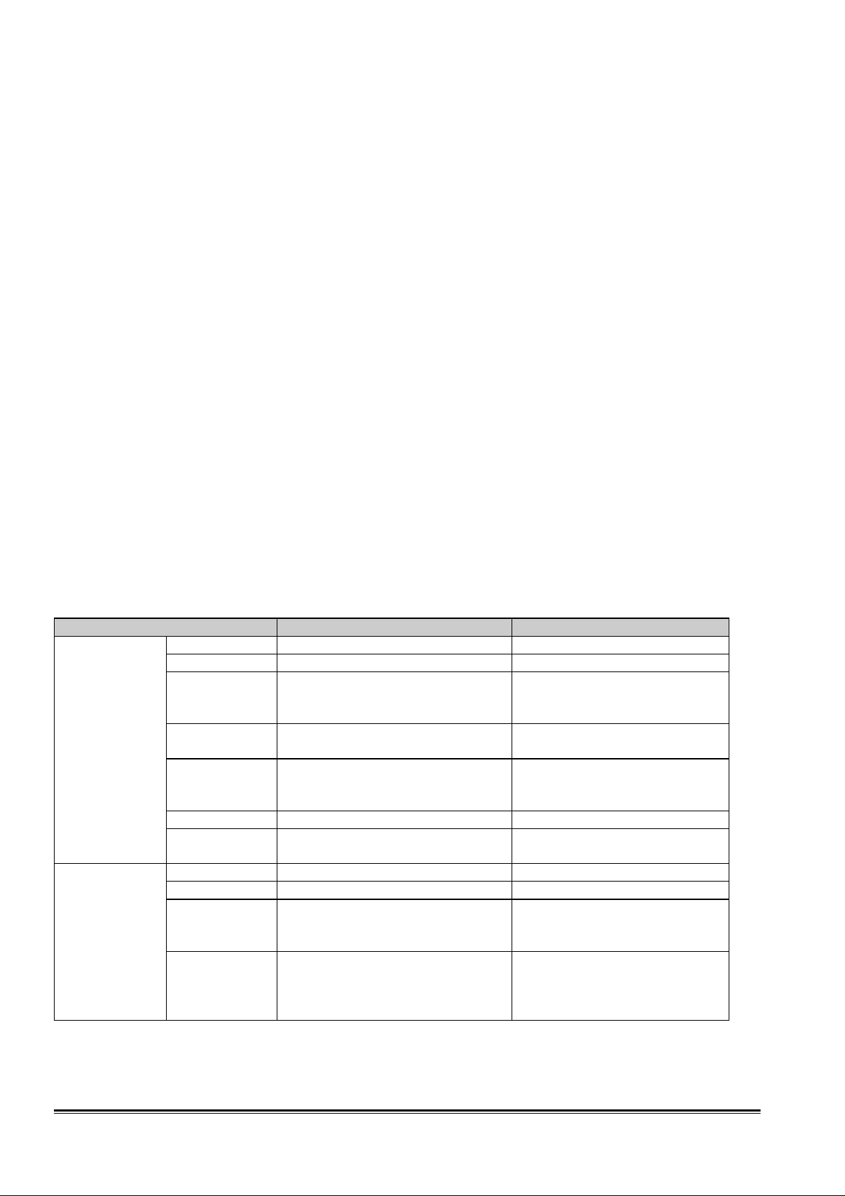
Analog input I: 15-pin D-SUB connector
PIN
1 RED VIDEO
2 GREEN VIDEO
3 BLUE VIDEO
4 GND
5 Self-test (Cable detector)
6 RED GND
7 GREEN GND
8 BLUE GND
9 PC5V
10 SYNC GND
11 GND
12 DDC DATA (SDA)
13 HORIZONTAL SYNC(H+V)
14 VERTICAL SYNC
15 DDC CLOCK (SCL)
SIGNAL
1 5
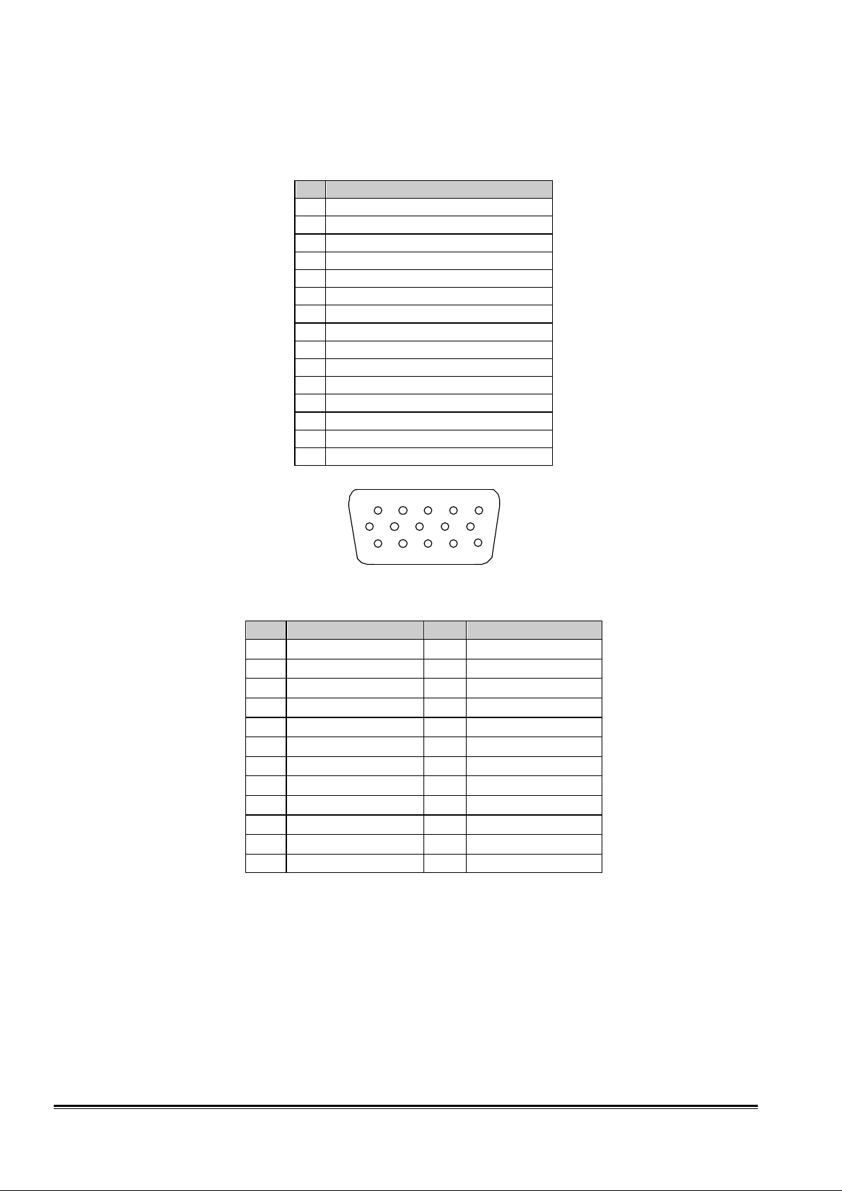
Digital input: 30-pin DVI-D connector
Pin Signal assignment Pin Signal assignment
1 TMDS RX2- 13 Floating
2 TMDS RX2+ 14 +5V Power
3 TMDS Ground 15 Ground
4 Floating 16 Hot Plug Detect
5 Floating 17 TMDS RX06 DDC Clock 18 TMDS RX0+
7 DDC Data 19 TMDS Ground
8 Floating 20 Floating
9 TMDS RX1- 21 Floating
10 TMDS RX1+ 22 TMDS Ground
11 TMDS Ground 23 TMDS Clock+
12 Floating 24 TMDS Clock-
6 10
11 15
15-pin D-SUB female
7
Confidential
Page 8
Dell 2000FP LCD Monitor Service Guide
Engineering Specification
24-pins DVI –D female
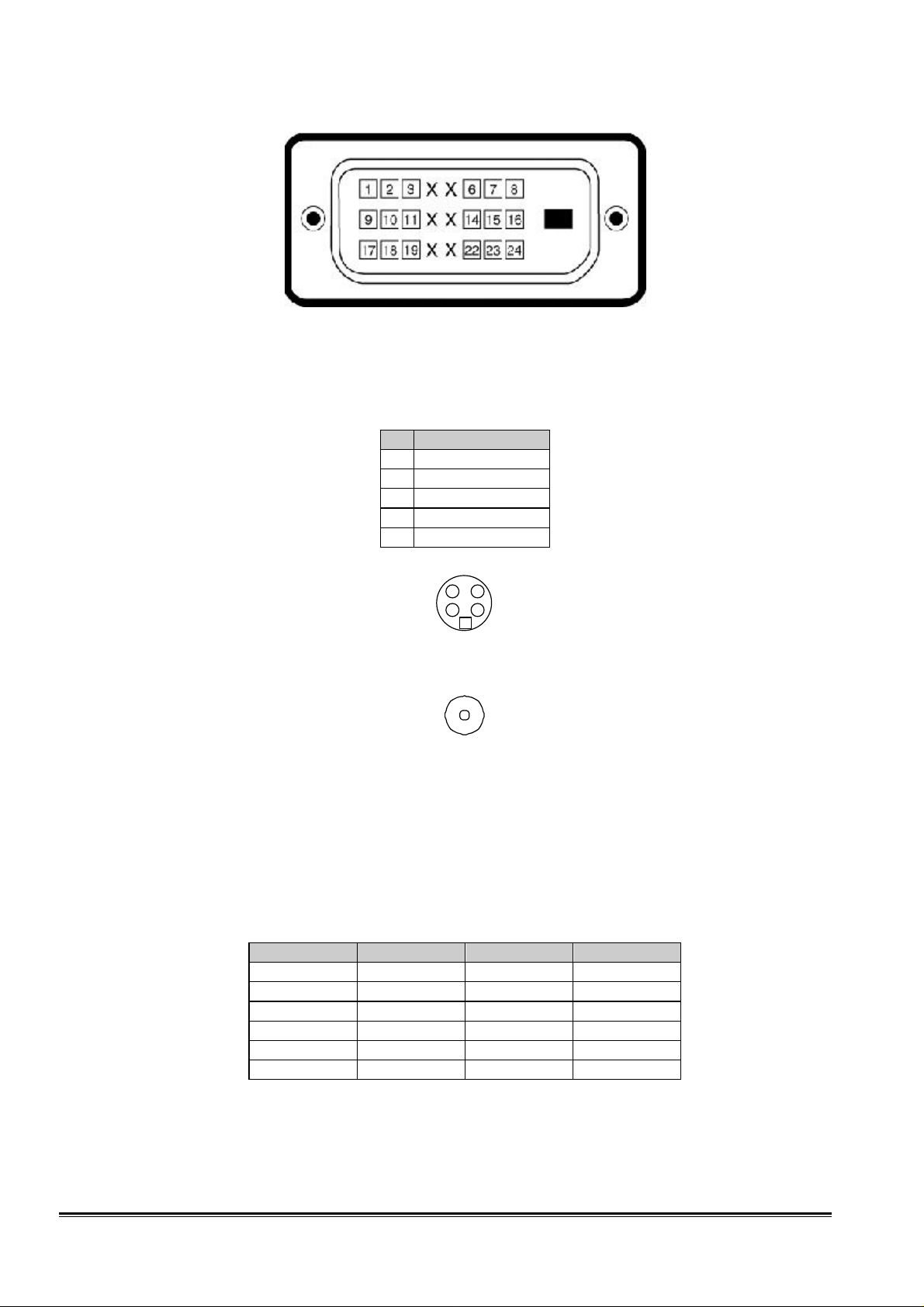
Video input I: S-VIDEO connector
PIN SIGNAL
1 GND
2 GND
3 LUMA
4 CHROMA
G GND
4-pin S-VIDEO female
Video input II: COMPOSITE video connector
Appendix 2 – Labels and Markings
Refer to RN-315
Appendix 3 – Preset Mode Timings
Resolution @ 60 Hz @ 70 Hz @ 75 Hz
640 × 480 P P
720 × 400 P
800 × 600 P P
1024 × 768 P P
1280 × 1024 P P
1600 × 1200 P
3 4
1
2
G
RCA jack
8
Confidential
Page 9
Dell 2000FP LCD Monitor Service Guide
Engineering Specification
Mode Synchro Polarity Dot Clock
(MHz)
1
2
3
4
5
6
7
8
9
10
H(Pixels) - 31.468 900 720 18 108 54
V(Lines) +
H(Pixels) - 31.469 800 640 16 96 48
V(Lines) -
H(Pixels) - 37.500 840 640 16 64 120
V(Lines) -
H(Pixels) + 37.879 1056 800 40 128 88
V(Lines) +
H(Pixels) + 46.875 1056 800 16 80 160
V(Lines) +
H(Pixels) - 48.363 1344 1024 24 136 160
V(Lines) -
H(Pixels) + 60.023 1312 1024 16 96 176
V(Lines) +
H(Pixels) + 63.981 1688 1280 48 112 248
V(Lines) +
H(Pixels) + 79.976 1688 1280 16 144 248
V(Lines) +
H(Pixels) + 75.000 2160 1600 64 192 304
V(Lines) +
28.321
25.175
31.500
40.000
49.500
65.000
78.750
108.000
135.000
162.000
Frequency
(KHz/Hz)
Total
Period
(Pixels)
Display
Period
(Pixels)
Front
Porch
Period
Synchro
Period
(Pixels)
(Pixels)
70.8 449 400 12 2 35
59.940 525 480 10 2 33
75.000 500 480 1 3 16
60.317 628 600 1 4 23
75.000 625 600 1 3 21
60.004 806 768 3 6 29
75.029 800 768 1 3 28
60.020 1066 1024 1 3 38
75.025 1066 1024 1 3 38
60.000 1250 1200 1 3 46
Back
Porch
Period
(Pixels
)
Resolution
720×400
640×480
640×480
800×600
800×600
1024×768
1024×768
1280×1024
1280×1024
1600×1200
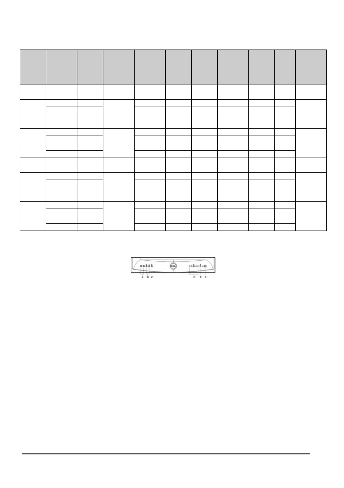
Appendix 4 – OSD Operation Procedures
Key definitions
There are 8 keys for user's control, which include “POWER”, “AUTO”, “INPUT”, “MENU”, “”, “”, “+”,
and “”. The following description defines the function of these keys.
“POWER” Mark F, to turn on/off the monitor.
“AUTO” Mark E, for auto adjusting vertical position, horizontal
“INPUT” To switch the input source among “D-sub”, “DVI-D”,
“MENU” Mark C, to enter OSD operation mode.
“” To select OSD items / “Hot Key” for contrast
“” To select OSD items / “Hot Key” for brightness
“+” To increase the value of the selected OSD item.
“–” To decrease the value of the selected OSD item.
position ,pixel clock and the phase.
“S-VIDEO”, and “COMPOSITE”.
adjustment.
adjustment.
9
Confidential
Page 10
Dell 2000FP LCD Monitor Service Guide
Engineering Specification
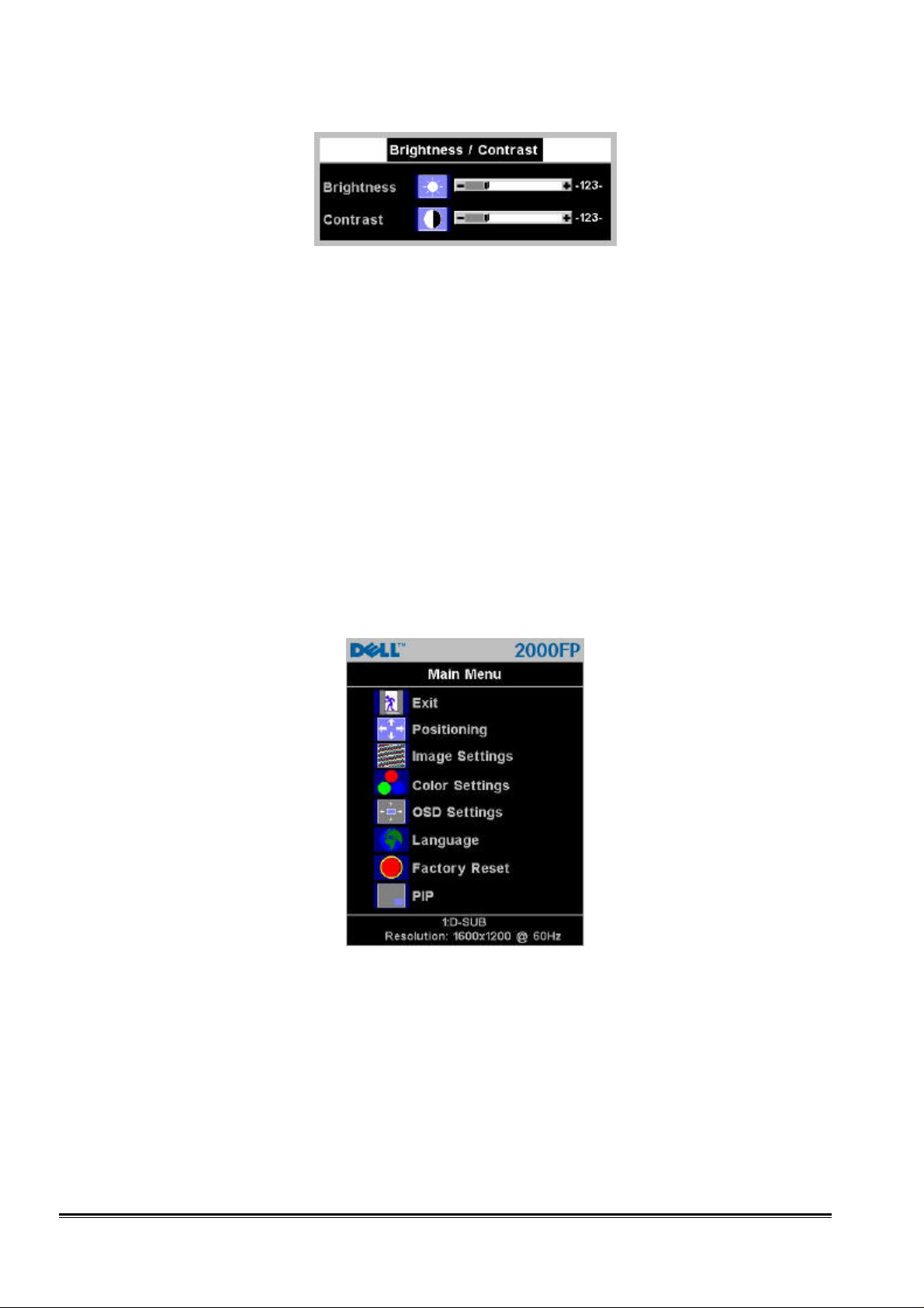
Brightness
The brightness function adjusts the luminance of the backlight in the LCM. With OSD menu off, push the ""
button to display the Brightness (and contrast) adjustment menu. Adjust Brightness first, then adjust Contrast only if
further adjustment is necessary.
Push the + button to increase the luminance;
push the – to decrease luminance (min. 0 ~ max 100).
Contrast
The contrast function adjusts the degree of difference between darkness and lightness on the monitor screen.
With OSD menu off, push the "" button to display the Contrast (and brightness) adjustment menu. For DVI-D input,
the contrast adjustment is disabled.
Push the + button to increase the contrast;
push the – button to decrease the contrast (min. 0 ~ max 100).
Main menu
“Positioning”, “Image Settings”, “Color Settings”, “OSD Settings”, “Language”, “Factory Reset” and “PIP”. The
following pages describe the details of these items.
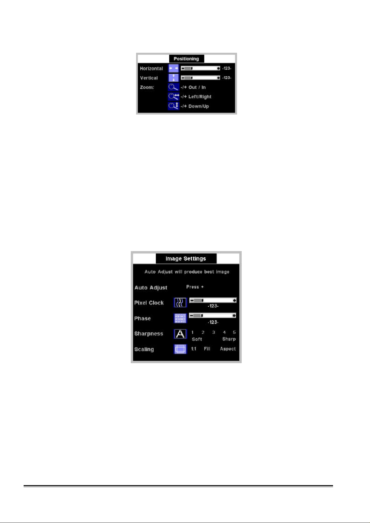
Positioning
Use "" or "" to select “Horizontal Position”, “Vertical Position”, and “Zoom” functions. When the selected item
is highlighted, the function is activated. Press "+" or "–" to adjust the “Horizontal Position”, “Vertical Position”, or
“Zoom” of the display.
Press “MENU” key to enter OSD main menu as figured below. The OSD main menu has 8 items including “Exit”,
Use "" or "" to select “Positioning” in the main menu and press "MENU" to enter “Positioning” sub-menu.
10
Confidential
Page 11
Dell 2000FP LCD Monitor Service Guide
Engineering Specification
Horizontal Position
Press +/– to adjust the horizontal position of the display and press "Menu" to return to the previous OSD page.
Vertical Position
Press +/– to adjust the vertical position of the display and press "Menu" to return to the previous OSD page.
Zoom In/Out
Press +/– to zoom In/Out the display and then press "Menu" to return to the previous OSD page. After Zoom In,
then the Zoom Left/Right, Down/Up functions can be activated.
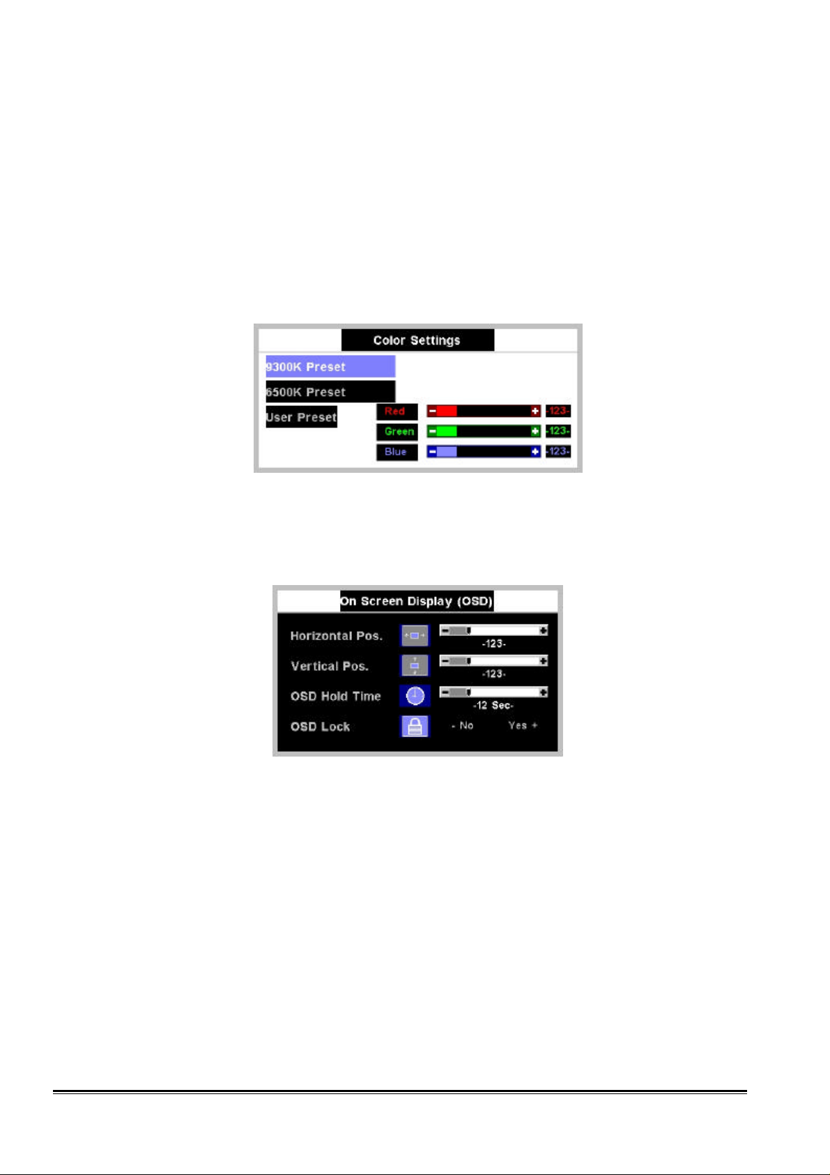
Image Settings
Use "" or "" to select “Image Settings” in the main menu and press "MENU" to enter “Image Setting” submenu. Use "" or "" to switch among “Auto Adjust”, “Pixel Clock”, “Phase”, “Sharpness”, Scaling, and “Image
Source” functions. When the selected item is highlighted, the function is activated then you can press "+" or "–" to
adjust the “Auto Adjust”, “Pixel Clock”, “Phase”, “Sharpness”, Scaling, and “Image Source” functions.
Auto Adjust
Press “+” to start “Auto Adjust” function.
Pixel Clock
Press +/– to adjust the value of “Pixel Clock” and press "Menu" to return to the previous OSD page.
Phase
Press +/– to adjust the value of “Phase” and press "Menu" to return to the previous OSD page.
Sharpness
Press "+" or "–" to adjust the degree of “Sharpness” and press "Menu" to return to the previous OSD page. It
smoothes an image which may help the eyes to see more detail.
11
Confidential
Page 12
Dell 2000FP LCD Monitor Service Guide
Engineering Specification
Scaling
Scaling optimizes the display for the type of software you are using. Includes “1:1”, “Fill”, and “Aspect”.
Under Image Setting sub-menu, press “Menu" to activate the scaling adjustment bar and by pressing "+" or "–" to
select among “1:1”, “Fill”, and “Aspect”. Then press "Menu" once to return to the Image Setting sub-menu or
twice to return to the main menu.
Color Settings
Color Settings adjusts the color temperature. Press "" or "" to select “Color Settings” function from main
menu and press "MENU" to enter “Color Setting” sub-menu. Press "" or "" to switch between “9300 Preset”,
“6500 Preset”, and “User Preset”. For S-VIDEO and COMPOSITE video input, the color settings adjust the Hue/Tint
and Saturation function.
User Preset
Press +/– to adjust the value of R, G, and B separately. Press "Menu" to return to the main menu.
OSD Settings
Use "" or "" to select “Horizontal Position”, “Vertical Position”, “OSD Hold Time”, and “OSD Lock”.
Horizontal Position
Press +/– to adjust the horizontal position of the OSD and press "Menu" to return to the previous OSD page.
Vertical Position
Press +/– to adjust the vertical position of the OSD and press "Menu" to return to the previous OSD page.
OSD Hold Time
Press +/– to adjust the hold time of the OSD and press "Menu" to return to the previous OSD page.
OSD Lock
By pressing “+” or “–“, you can lock or unlock the OSD. Then press "Menu" to return to the previous OSD page.
Language
Use "" or "" to select different languages from English, Español, Français, Deutsch, and Japanese. Then press
"Menu" to return to the previous OSD page.
Confidential
12
Page 13
Dell 2000FP LCD Monitor Service Guide
Engineering Specification
Factory Preset
The function of “Factory Preset” is to reset control settings to the factory preset values for the selected group of
functions. Press "" or "" to select “Position Setting”, “Color Setting”, and “All setting” and then press “Menu” to
execute.
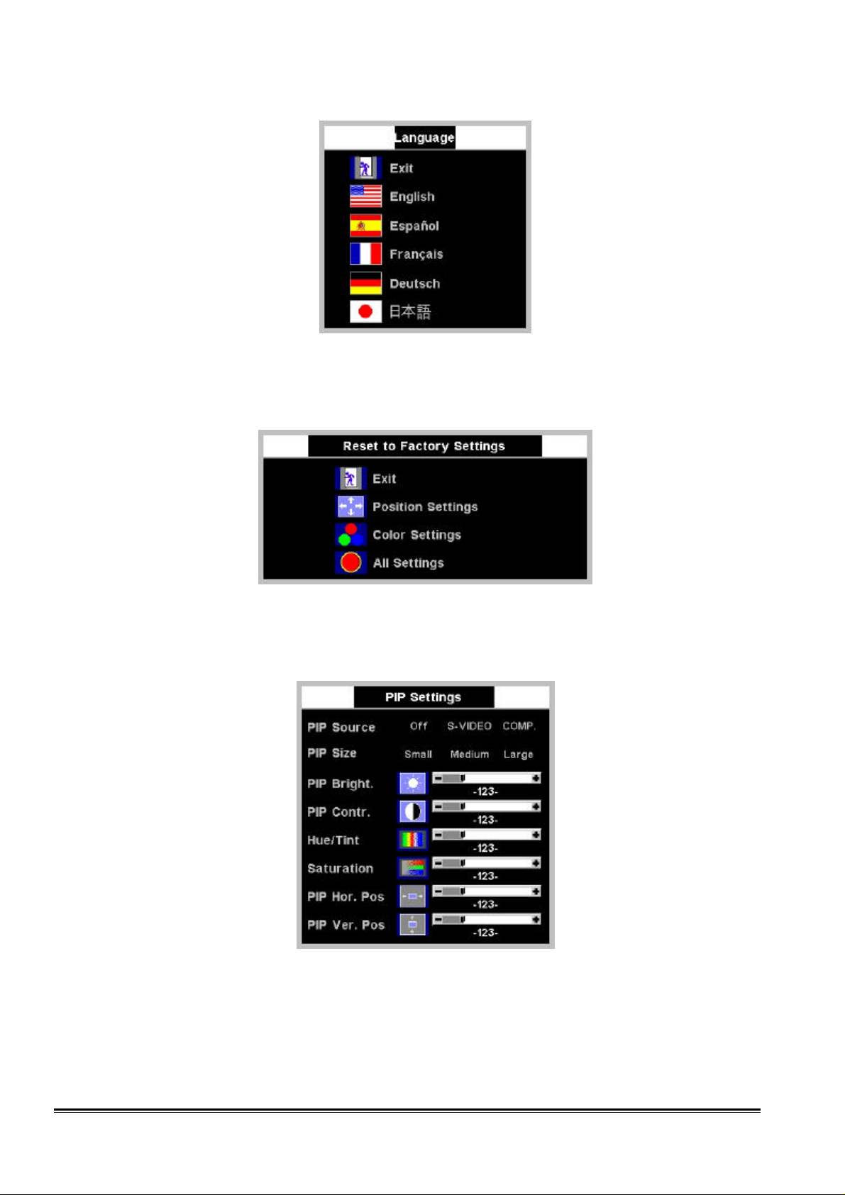
PIP Settings
The function of “PIP Settings” is to set the Picture-In-Picture window. Press "" or "" to select “PIP Source”,
“PIP Size”, “PIP Bright”, “PIP Contr.”, “Hue/Tint”, “Saturation”, “PIP Hor. Pos”, or “PIP Ver. Pos” and press “+”
and “-“ to adjust the item selected.
PIP Source
Use +/– to select input sources from “S-VIDEO” and “COMPOSITE”. Or “Off” to turn off PIP window. Press
"Menu" to return to the previous OSD page.
PIP Size
13
Confidential
Page 14
Dell 2000FP LCD Monitor Service Guide
Engineering Specification
Use +/– to select “Small”, “Medium”, and “Large” PIP window. Press "Menu" to return to the main menu.
PIP Bright.
Press +/– to adjust the brightness of PIP window. Press "Menu" to return to the main menu.
PIP Contr.
Press +/– to adjust the contrast of PIP window. Press "Menu" to return to the main menu.
PIP Hue/Tint
Press +/– to adjust the hue/tint of PIP window. Press "Menu" to return to the main menu.
PIP Saturation
Press +/– to adjust the saturation of PIP window. Press "Menu" to return to the main menu.
PIP Hor. Position
Press +/– to adjust the PIP window position horizontally. Press "Menu" to return to the main menu.
PIP Ver. Position
Press +/– to adjust the PIP window position vertically. Press "Menu" to return to the main menu.
Appendix 5 – Special Indication
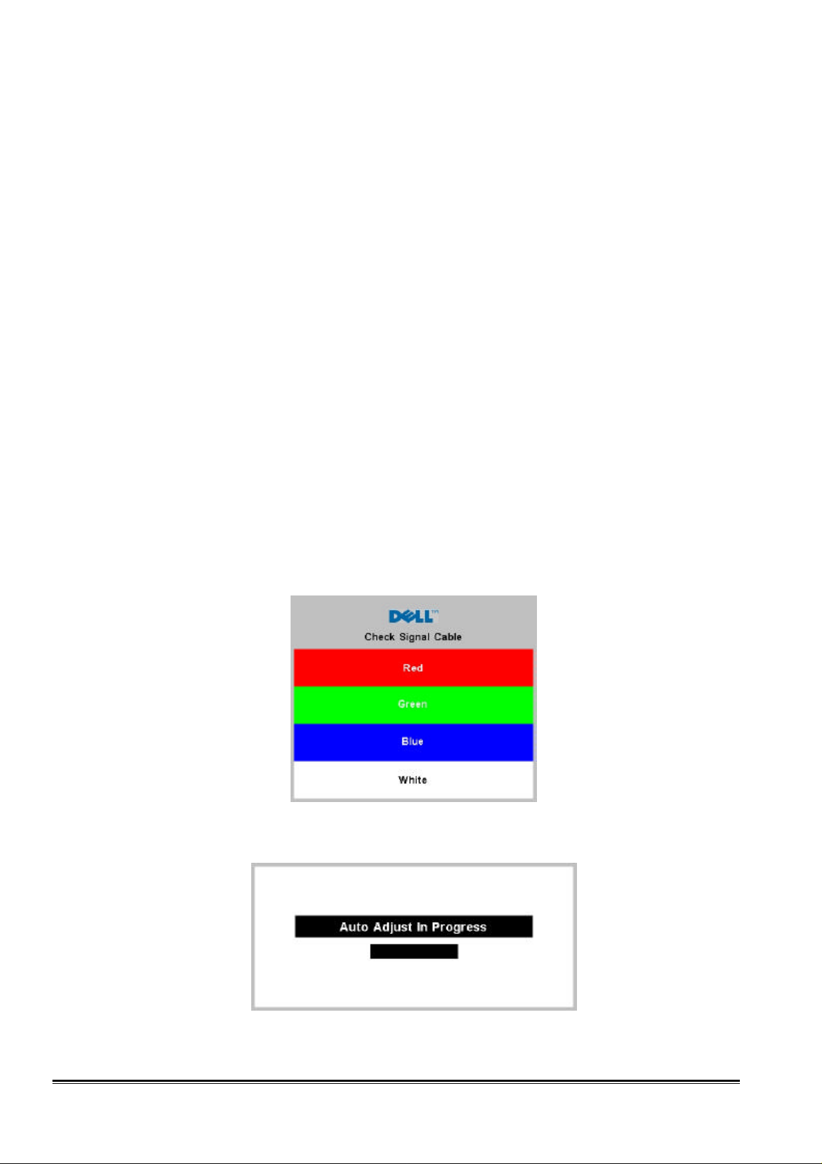
Self Test Feature Check (STFC)
The floating 'Dell - Self Test Feature Check' dialog will appear on the screen (against a black background) if the
signal cable is detached. The monitor should stay in STFC mode until the input selection button is pressed, or the
cable is re-attached.
“Auto Adjust In Progress” message
When monitor is doing auto adjustment, the “Auto Adjust In Progress” message will appear on the screen.
Confidential
14
Page 15
Dell 2000FP LCD Monitor Service Guide
Engineering Specification
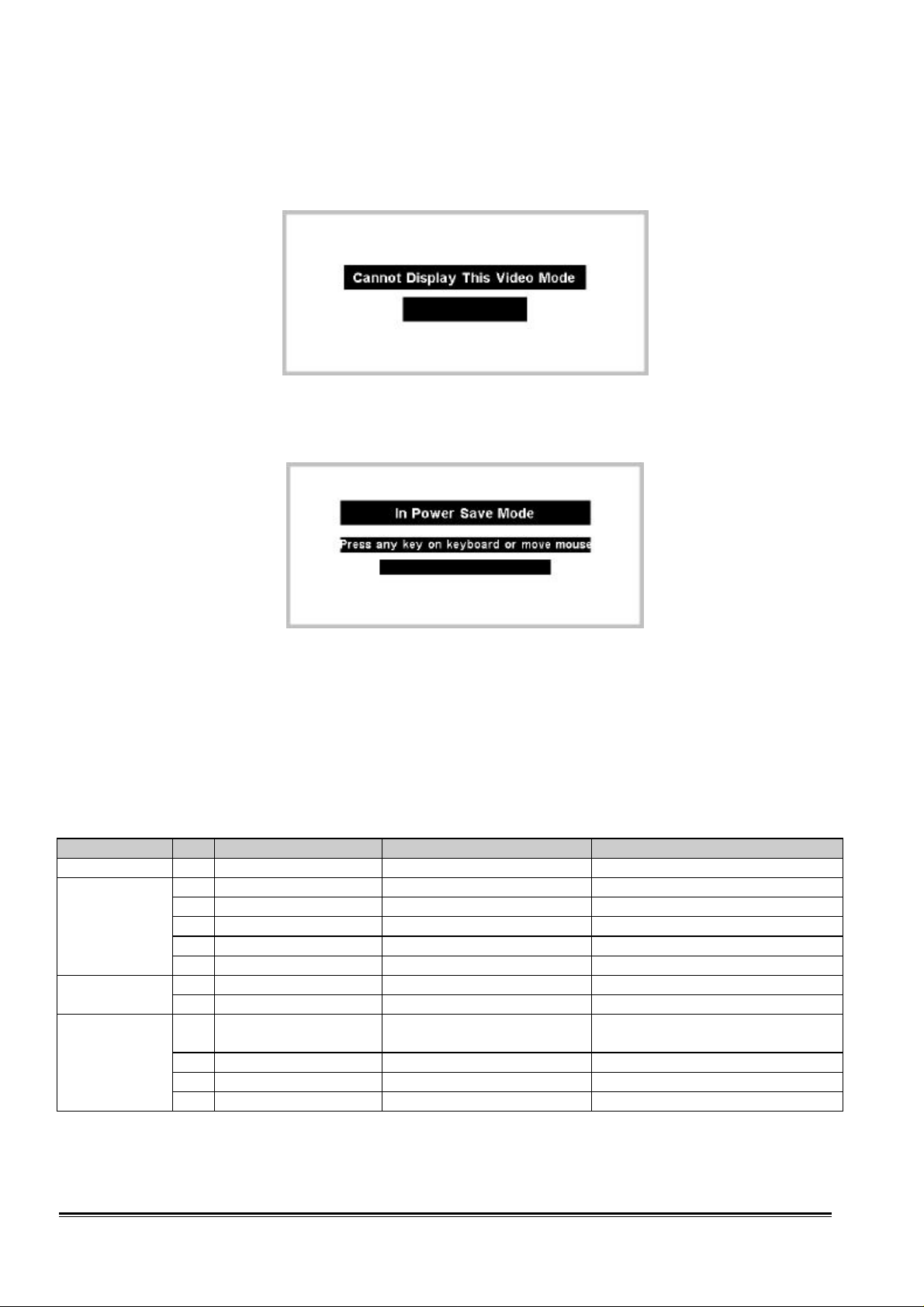
“Cannot Display This Video Mode” message
When the D-sub input pixel clock over 200MHz or the input pixel clock over 162 MHz of DVI-D, it cannot be
displayed, the warning message “Cannot Display This Video Mode” will appear on the screen.
“In Power Save Mode” message
When the computer system is under power saving mode, the monitor will show the message of “In Power Save
Mode” before entering the DPMS mode.
Appendix 6 – Translation List
TBD
Appendix 7 – EDID Content
D-SUB port
Item Byte Description Data Hex Remarks
HEADER 8 00, FF, FF, FF, FF, FF, FF, 00
Vendor
Product ID
Revision
Basic Display
Parameter and
Features
2 Mfg. Name 10,AC DELL
2 Product Code 02,A0 2000FP
4 Serial Number (varies) 34,33,32,31 4321
1 Mfg. week (varies) 14 20th week
1 Mfg. year (varies) 0B 2001
1 Version 01 1 EDID Version
1 Revision 03 3
1 Video input 0E 0.7Vpp analog RGB, supports
1 Max Horiz size cm 29 40.8 cm
1 Max Vert size cm 1F 30.6 cm
1 Gamma Value 96 Gamma=2.5
separate, composite sync and SOG
Confidential
15
Page 16

Dell 2000FP LCD Monitor Service Guide
Basic Display
Engineering Specification
1 Feature Support EB standby/suspend/off
preferred timing
default GTF supported
Color
Characteristics
Established
Timings
Standard
timing
Detailed
Timing
Description
Monitor
Descriptor
18 Monitor Name 00,00,00,FC,00,44,
18 Range Limit 00,00,00,FD,00,38,
Extension Flag 1 00
Check sum 1 00 (varies)
10 R,G,B 4C,40,A1,57,4C,
97,26,1C,50,54
1 Timing I A5
xR=0.63 yR=0.34 xG=0.30 yG=0.59
xB=0.15 yB=0.11 xW=0.313 yW=0.329
720×400 @ 70: Y
720×400 @ 88: N
640×480 @ 60: Y
640×480 @ 67: N
640×480 @ 72: N
640×480 @ 75: Y
800×600 @ 56: N
800×600 @ 60: Y
1 Timing II 4B
800×600 @ 72: N
800×600 @ 75: Y
832×624 @ 75: N
1024×768 @ 87: N
1024×768 @ 60: Y
1024×768 @ 70: N
1024×768 @ 75: Y
1280×1024 @ 75: Y
1 Mfg. reserved 00 Not used
2 ID #1 81,80 1280×1024,60Hz
2 ID #2 A9,40 1600×1200,60Hz
10 ID # 3,4,5, 6, 7, and 8 01,01,01,01,01,01,
Unused
01,01,01,01,01,01
18 Detailed Timing
(Preferred timing mode)
18 Serial No 00,00,00,FF,00,30,30,33,30,50
48,3F,40,30,62,B0,32,40,40,
C0,13,00,6F,13,11,00,00,1E
,39,37,52,31,32,33,34,0A
1600×1200,60Hz
Serial No.
0030P - 97R - 1234
“DELL 2000FP”
45,4C,4C,20,32,30,
30,30,46,50,0A,20
V range 56-76Hz
4C,1F,50,10,00,0A,
20,20,20,20,20,20
H range 31-80kHz
Max pixel clk 162Mhz
DVI–D port
HEADER 8 00, FF, FF, FF, FF, FF, FF, 00
Vendor
Product ID
Revision
Confidential
Item Byte Description Data Hex Remarks
2 Mfg. Name 10,AC DELL
2 Product Code 03,A0 2000FP
4 Serial Number (varies) 34,33,32,31 4321
1 Mfg. week (varies) 14 20th week
1 Mfg. year (varies) 0B 2001
1 Version 01 1 EDID Version
1 Revision 03 3
1 Video input 80 digital port
16
Page 17

Dell 2000FP LCD Monitor Service Guide
Engineering Specification
Color
Characteristics
Established
Timings
Standard
timing
Detailed
Timing
Description
Monitor
Descriptor
18 Monitor Name 00,00,00,FC,00,44,
18 Range Limit 00,00,00,FD,00,38,
Extension Flag 1 00
Check sum 1 00 (varies)
1 Max Horiz size cm 29 40.8 cm
1 Max Vert size cm 1F 30.6 cm
1 Gamma Value 96 Gamma=2.5
1 Feature Support EB standby/suspend/off
preferred timing
default GTF supported
10 R,G,B 4C,40,A1,57,4C,
97,26,1C,50,54
1 Timing I A5
xR=0.63 yR=0.34 xG=0.30 yG=0.59
xB=0.15 yB=0.11 xW=0.313 yW=0.329
720×400 @ 70: Y
720×400 @ 88: N
640×480 @ 60: Y
640×480 @ 67: N
640×480 @ 72: N
640×480 @ 75: Y
800×600 @ 56: N
800×600 @ 60: Y
1 Timing II 4B
800×600 @ 72: N
800×600 @ 75: Y
832×624 @ 75: N
1024×768 @ 87: N
1024×768 @ 60: Y
1024×768 @ 70: N
1024×768 @ 75: Y
1280×1024 @ 75: Y
1 Mfg. reserved 00 Not used
2 ID #1 81,80 1280×1024,60Hz
2 ID #2 A9,40 1600×1200,60Hz
10 ID # 3,4,5, 6, 7, and 8 01,01,01,01,01,01,
Unused
01,01,01,01,01,01
18 Detailed Timing
(Preferred timing mode)
18 Serial No 00,00,00,FF,00,30,30,33,30,50
48,3F,40,30,62,B0,32,40,40,
C0,13,00,6F,13,11,00,00,1E
,39,37,52,31,32,33,34,0A
1600×1200,60Hz
Serial No.
0030P - 97R - 1234
“DELL 2000FP”
45,4C,4C,20,32,30,
30,30,46,50,0A,20
V range 56-76Hz
4C,1F,50,10,00,0A,
20,20,20,20,20,20
H range 31-80kHz
Max pixel clk 162Mhz
Confidential
17
Page 18

Dell 2000FP LCD Monitor Service Guide
Engineering Specification
Appendix 8 – Power State Maximums
CUP
State
ON Active 60W -- Green
Stand-by Sleep 5W Amber
Suspend Sleep 5W Amber
OFF Sleep 5W Amber
Monitor
State
Maximum
Power
Maximum Recovery
time
LED State
Appendix 9 – LCD Module Specification
ITEMS LG.PHILIPS LM201U1-A1
Diagonal size 20.1 inches (51 cm)
Pixel arrangement 1600×1200×R,G,B
Display mode Normally black IPS
Viewing angle technology Wide view angle
Natural color depth 24 bits
Input I/F TMDS
External dimensions 467.8(W)×361.0(H)×32.0(D)
Surface treatment Hard coating 3H, Anti-glare treatment
Backlight Operating Lifetime
(Brightness=50%)
Maximum starting time
Under operation conditions
30,000Hrs (min)
2 sec
Appendix 10 – Mechanical Specification
All plastics Resin
ITEMS Specification
Material GEC2800/Bayer FR2000/CHIEL NH-1000T
Texture ACM standard
UV <1
Heat Defection Temp.
Flame Retardant Pkg Triarylphosphate esters
Flammability V0
Color Midnight gray/Pearl white
Mechanical Assembly
ITEMS Specification
Gap LCD Panel/bezel gap<1.2mm
Gap front/rear cover 0.5<gap<1.5mm
Gap between other plastic parts <1.0mm
Step in the same plastic <0.5mm
Step between different plastics <0.8mm
LCD module centering Viewable area cannot be hidden by the front bezel
80°C
Confidential
18
Page 19

Dell 2000FP LCD Monitor Service Guide
Engineering Specification
Dimensions
ITEMS Specification
Monitor weight Approximately 11.7kg
Footprint W×D 417.76×266.56mm
Cabinet dimension W×H×D 512.5(W) X509(H) X226.5 (D) mm
Bezel opening 409.9(W)×308(H) mm
Monitor height 509mm
Tilt -5~+15 degree
Cosmetic inspection shall be performed under specific time, distance, and lighting requirements as detailed below. This is
to be the first test performed on any new product, and is to be performed under normal lighting of 500 lux as measured
perpendicular to the work surface, and 250 lux as measured perpendicular to the center of the display screen, per ISO 9241-3,
unless otherwise specified. No magnification is to be used except in the case of measuring LCD polarizer or screen defects.
During a visual inspection, a judgment must be made as to whether or not the end user would consider the flaw(s) objectionable.
During this inspection, only visual qualities are to be considered. The unit shall exhibit no objectionable defects under the
following inspection time and viewing distance criteria:
- Front panels: Inspect for 10 seconds at viewing distance of 500 mm.
- All other sides: Inspect for 5 seconds each at a viewing distance of 500 mm.
The following items are unacceptable if found during the time given for the inspection:
1. Missing parts.
2. Deformed case parts, control knobs, feet, or other parts.
3. Broken case or other parts.
4. Scratches greater than 0.5mm wide, or greater than 10 mm long, or greater than 0.2 mm deep.
5. Any scratches on the painted surface of any panel which allows the substrate material to show through
6. Any dirt or finger print
Appendix 11 – Regulatories
Safety
Agencies
P
UL R1950, £Other
P
CSA R950, £Other
P
TUV RTUV, RGS, RErgo
P
Nemko
Semko
Demko
Fimko
P
DHHS
P
CCIB
P
Other CB report
EMC
Agencies
P
FCC £FCC-A, RFCC-B
P
CE
P
VCCI £VCCI-I, RVCCI-II
P
C-Tick
P
BCIQ (BSMI)
P
Other IC/ Canada
Confidential
19
Page 20

Dell 2000FP LCD Monitor Service Guide
Engineering Specification
Other
Agencies
P
EPA
TCO92
P
TCO95
TCO99
E2000
P
GOST
P
PCBC
P
PSB
P
EZU
P
PTB
Appendix 12 – LCD Module Defects
Items Spec
AQL
Bright dot
Dot defect
Dark dot
Foreign
Material
Major defect AQL=0.65%
Minor defect AQL=1.5%
1 dot N<=5
Adjacent 2 dots N<=1
Adjacent 3 dots Not allowed
Min. distance L>=15mm
Total amount of Bright dot N<=5
1 dot N<=10
Adjacent 2 dots N<=2
Adjacent 3 dots Not allowed
Min. distance L>=15mm
Total amount of Dark dot N<=10
Total N<=10
0.01<=W<=0.1
Scratch (linear type)
0.3<=L<=7.0
N<=4 Polarizer
Dent (circular type)
Dot shape
0.2<=D<=0.5
N<=4
0.2<=D<=0.5
N<=4
0.05<=W<=0.1
Line shape
0.3<=L<=4.0
N<=4
20
Confidential
Page 21

Dell 2000FP LCD Monitor Service Guide
1
3 9
7
Engineering Specification
Appendix 13 – FOS Specifications (Draft)
Values Parameter Symbol
Min. Typ. Max.
Contrast Ratio CR 250 350 - 2
Luminance, white SBWH 200 250 - Cd/m2 3
Luminance uniformity 70 - - % 4
CIE Color Coordinates
Red
Green
Blue
White
Viewing Angle by CR ≥ 10
x axis, right (Ô =0º)
x axis, left(Ô =180º)
y axis, up(Ô =90º)
y axis, down (Ô =270º)
Response Time Tr - 39 45 msec 6
x
y
x
y
x
y
x
W
yW
è
è
è
è
R
R
G
G
B
B
0.600
0.310
0.270
0.560
0.120
0.080
0.283
0.299
80
80
80
80
0.630
0.340
0.300
0.590
0.150
0.110
0.313
0.329
-
-
-
-
0.660
0.370
0.330
0.620
0.180
0.140
0.343
0.359
-
-
-
-
Units Notes
(See Appendix 14)
Degree
Appendix 14 – FOS Notes
1. Test conditions: (unless otherwise specified, all measurement shall be made under the test conditions below)
5
- Ambient illumination level: dark (<10 lux)
- Ambient temperature: 25 oC
- Warm-up: 30 minutes
- Input signal timing: VESA UXGA @ 60Hz on video generator
- User control: Brightness = 90%, Contrast = 50%, Color temperature = Factory user preset mode
- Test equipment: Prichard 880 or equivalent
- Measurement locations on the flat panel:
2
4
Column #160
2. Contrast Ratio CR= Surface luminance (full white pattern) / Surface luminance (full black pattern)
3. Luminance SBWH=L5
4. Luminance variation SBV = Min (L1, L2,…L9) / Max (L1, L2,…L9) ×100%
5. Viewing angle:
Measurement is done at position 5
Column #800
5
8
Column #1440
6
Row #120
Row #600
Row #1080
Confidential
21
Page 22

Dell 2000FP LCD Monitor Service Guide
E
100
90
10
0
Engineering Specification
Viewing angle origine is the axis normal to the flat panel. Left (L) and right (R) values are the maximum angles for
which CR 10. Up (U) and down (D) values are the maximum angles for which CR 10.
See figure below:
Normal
Ô
TrD
y
Ô = 90o Up
x
Ô = 0o Right
TrR
white
black
è
Ô = 180o Left
Ô = 270o Down
6. Response time
TrR measures the transition time of L1 relative luminance from white to black state, from 90% to 10% (see graph
below)
TrD measures the transition time of L1 relative luminance from black to white state, from 10% to 90% (see graph
below)
%
Optical
Response
white
7. White balance and chromaticity: measured at Center position.
8. Dark luminance: at any point
Specific conditions: dark luminance is measured in a dark room (< 10 lux).
Appendix 15 – Shipment Conditions
ITEM State
Brightness 90%
Contrast 50%
OSD-Color temp. 6500K
OSD-Image size Fill
OSD-Language English
OSD-Timeout 20 sec
Confidential
22
Page 23

Dell 2000FP LCD Monitor Service Guide
Alignment Procedure
Casing input
LCM sorting
Use UXGA 60Hz with Full-White / Full-Black / Pure-R / Pure-G / Pure-B patterns to check LCM.
I/F board barcode scanning
Mechanical offset adjustment
DDC Programming
Preset timing check
D-SUB port / DVI port
Check the following preset timings with General pattern:
No. Mode H V
1 720×400 @ 70Hz 31.468 70.8
2 640×480 @ 60Hz 31.469 59.940
3 640×480 @ 75Hz 37.500 75.000
4 800×600 @ 60Hz 37.879 60.317
5 800×600 @ 75Hz 46.875 75.000
6 1024×768 @ 60Hz 48.363 60.004
7 1024×768 @ 75Hz 60.023 75.029
8 1280×1024 @ 60Hz 63.981 60.020
9 1280×1024 @ 75Hz 79.976 75.025
10 1600×1200 @ 60Hz 75.000 60.000
PIP function
No. Monitor settings Signal source Criteria
1 S-Video with DVD-NTSC
Main source: D-SUB or DVI displaying normally
PIP source: S-Video and PIP size: Large
2
3 Comp. with DVD-NTSC
Main source: D-SUB or DVI displaying normally
PIP source: Comp. and PIP size: Large
4
S-Video with DVD-PAL
Comp. with DVD-PAL
DVD video is displaying normally.
Video function
No. Monitor settings Signal source Criteria
1 S-Video with DVD-NTSC
Main source: S-Video
2
3 Comp. with DVD-NTSC
Main source: Comp. video
4
S-Video with DVD-PAL
Comp. with DVD-PAL
DVD video is displaying normally.
1
Confidential
Page 24

Dell 2000FP LCD Monitor Service Guide
Alignment Procedure
Brun in
Set the monitor to Burn-In mode before burning in.
Casing output
Performance checking
Powering up with factory mode
Connect D-SUB signal and the power.
Hold ‘Auto’ and ‘Source’ keys at the same time for 5 sec to let the monitor power up in the factory mode.
D-SUB port
Use UXGA 60Hz with 5-Mosaic pattern to calibrate the ADCs.
Check the following preset timings with General pattern:
No. Mode H V
1 720×400 @ 70Hz 31.468 70.8
2 640×480 @ 60Hz 31.469 59.940
3 640×480 @ 75Hz 37.500 75.000
4 800×600 @ 60Hz 37.879 60.317
5 800×600 @ 75Hz 46.875 75.000
6 1024×768 @ 60Hz 48.363 60.004
7 1024×768 @ 75Hz 60.023 75.029
8 1280×1024 @ 60Hz 63.981 60.020
9 1280×1024 @ 75Hz 79.976 75.025
10 1600×1200 @ 60Hz 75.000 60.000
Press Auto-Adjustment if needed.
Check if the picture is OK and no jitters are found. Any noise on the picture will not be acceptable.
DVI port
Connect DVI-D signal.
Check the following preset timings with General pattern:
No. Mode H V
1 720×400 @ 70Hz 31.468 70.8
2 640×480 @ 60Hz 31.469 59.940
3 640×480 @ 75Hz 37.500 75.000
4 800×600 @ 60Hz 37.879 60.317
5 800×600 @ 75Hz 46.875 75.000
6 1024×768 @ 60Hz 48.363 60.004
7 1024×768 @ 75Hz 60.023 75.029
8 1280×1024 @ 60Hz 63.981 60.020
9 1280×1024 @ 75Hz 79.976 75.025
10 1600×1200 @ 60Hz 75.000 60.000
Check if the picture is OK and no jitters are found. Any noise on the picture will not be acceptable.
2
Confidential
Page 25

Dell 2000FP LCD Monitor Service Guide
Alignment Procedure
PIP function
No. Monitor settings Signal source Criteria
1 S-Video with DVD-NTSC
Main source: D-SUB or DVI displaying normally
PIP source: S-Video and PIP size: Large
2
3 Comp. with DVD-NTSC
Main source: D-SUB or DVI displaying normally
PIP source: Comp. and PIP size: Large
4
S-Video with DVD-PAL
Comp. with DVD-PAL
DVD video is displaying normally.
Any noise will not be acceptable
Video function
No. Monitor settings Signal source Criteria
1 S-Video with DVD-NTSC
Main source: S-Video
2
3 Comp. with DVD-NTSC
Main source: Comp. video
4
S-Video with DVD-PAL
Comp. with DVD-PAL
DVD video is displaying normally.
Any noise will not be acceptable
Default settings
No. Item Default values
1 Brightness 90
2 Contrast 50
3 Color temperature 6500K
4 Image scaling Fill
5 Language English
6 OSD hold time 20
Color temperatures
Color temperature The x coordinate The y coordinate
9300K 283±30 297±30
6500K 313±30 329±30
Brightness uniformity
Input source: D-SUB or DVI-D running at UXGA 60Hz
No. Item Spec
1 Brightness (center point) 250 cd/m2
2 Uniformity (9 points) Lmin/Lmax > 70%
Power consumption
No. Item Spec
1 Power saving < 5W
2 Normal operation 60W
Serial Number recording & DDC checking (Both D-SUB and DVI)
On-Line QA / Cosmetic Inspection
Packing
3
Confidential
Page 26

Dell 2000FP LCD Monitor Service Guide
Circuit Operation Theory
Introduction
This specification describes a 20.1" UXGA TFT LCD monitor with a power adapter. It supports maximal resolution up to
1600×1200 and analog and digital inputs with DPMS. It also supports S-VIDEO and COMPOSITE video inputs. It features:
- Auto Key (Automatic adjustment function)
- User control: on/off switch, OSD control, brightness and contrast quick access, and input source selection keys
- Multi-timing support
- High quality advanced scaling function
- Power on/off indicator
- 4 input indication LEDs
- Universal power adapter
- 0.255(W)×0.255(H) mm dot pitch LCD panel
- PIP (picture in picture) feature
- Fancy OSD features:16-bit bitmap color for the splash screen, 16 pallets out of 16 bits colors for the OSD icons.
Block diagram
FP2036 consists of an LCD module with 6 lamps, an Inverter, an Interface board with DC-DC, ADC, DVI and Video
circuit, and 2 control boards. There is one adaptor converting AC input to DC 20V. The block diagram is shown below:
LCD module with 6 lamps (backlight)
Main board with DC-DC circuit
Inverter
Control board
D-Sub DVI-D S-Video Composite
DC 20V adapter
Confidential
1
Page 27

Dell 2000FP LCD Monitor Service Guide
Circuit Operation Theory
Circuit operation theory
Block diagram
D-SUB
DVI-D
S-VIDEO
COMP.
140MHz
ADC
100MHz
ADC
Single Link
TMDS
Video
Decoder
Flash Rom
GPORT
PW171
VPORT
Deinterlacer
8 Mbits
Clock
Generator
TMDS
Trans-
mitter
Keypad RS232
UXGA
1600×1200
LCM
Confidential
2
Page 28

Dell 2000FP LCD Monitor Service Guide
Circuit Operation Theory
Circuit operation theory
A basic operation theory for the interface board is to convert input signal into digital RGB or YUV data.
Analog RGB signal is converted to digital signal through ADC. DVI-D signal is converted through TMDS
receiver. Video decoder is used to capture and scale S-typed and composite video signal. It is able to decode the
color of PAL , SECAM, and NTSC system. The microprocessor PW171 receives graphic and video data and
optimizes the image automatically. It also supports PIP function, input source selection, 16 color from a 64k
palette bitmap OSD, on-chip frame buffer providing frame rate conversion, and keypad controlling. The output
data are sent to LCD module through a T MDS transmitter.
Main function ICs
A/D converter
2 AD9884A’s are used as ADCs. Master one goes up to 140MHz and the slave one 100MHz. The maximal
resolution supported is UXGA 60Hz, which has a pixel clock of 162MHz. Any supported mode whose
pixelclock is under 140MHz will use only master ADC (running up to 140MHz). Timings that have pixel clocks
between 140MHz and 200MHz will use both ADCs running up to 100MHz each to perform a 200Mhz ADC
virtually. When 2 ADCs are utilized, one of them takes care of the sampling at even clocks and the other at odd
clocks. 24-bit digital RGB data are then converted and go to G-Port of PW171. Notice that these digital data are
wired-ORed with the data from TFP401, TMDS receiver at DVI-D port.
TMDS receiver
TI TFP401 is used as a TMDS receiver. The maximal pixel clock is 162MHz, 1600×1200@60Hz. 24-bit data
(dual-pixel mode) are decoded and go to G-Port of PW171. These data are wired-ORed with the data from 2
AD9884’s, A/D converters at D-SUB port.
Video decoder
Philips SAA7114H is used as a video decoder to decode signals from S-Video and Composite Video. It decodes
the video signal of PAL, SECAM and NTSC formats. The decoded data contain 8-bit UV color data and 8-bit
luminance data. The data go to the video de-interlacer.
Video de-interlacer
Genesis gmVLX1A-X is used to de-interlace input video data. Video is required to be de-interlaced for better
display on progressive scan monitors. The gmVLX1A-X requires an external RAM to store one previous field.
De-interlaced data go to V-Port of PW171.
Image processor
Pixelworks image processor PW171 is a highly integrated "system-on-a-chip" that interfaces analog ,digital, and
video input formats. An embedded SDRAM frame buffer and memory controller perform frame rate conversion.
An integrated OSD controller provides bit-mapped based OSDs with 16 colors out of a 64K color palette.
TMDS transmitter
SiliconImage SiI160 is used to perform TMDS dual pixel data transmission . It transmits the displaying data to
the LG-Philips LM201U1-A3 UXGA LCM.
Flash ROM
A flash ROM is used to store the firmware program used by the image processor PW171.
Confidential
3
Page 29

Dell 2000FP LCD Monitor Service Guide
Circuit Operation Theory
DDC IC for both D-SUB and DVI
24C02 is used to support DDC2B function in both D-SUB and DVI ports. EDID data used for D-SUB and DVI
are stored in different 24C02’s respectively.
EEPROM
A 24C16 (2048 bytes) is used to store user settings, such as user timing settings, brightness/contrast, color
temperature, etc.
DC-DC converter
Buck Converter
L701
68U
L703
OPEN
C713
100U
16V
D703
RB060L-40
+ +
C712
100U
16V
C711
100U
16V
R719
1.1K
(1%)
+
R714
3.3K
+
Q703
2N3904
R737
20K
R715
22
Q704
2N3906
R733
2.7K
R732R731
0
GND
Q705
SI4431DY
18
2
3
4
S
S
S
RB060L-40
D
D
D
DG
D701
7
6
5
Fig.1
Fig.1 shows a typical Buck converter circuit. Q705 is a switching device. Q703, Q704 are a totem pole which
gets enough ability to drive P-MOS. When pin4 of Q705 is low, Q750 turns on. At high level, Q750 turns off.
So, pulse waveform will appear at D-terminal of Q705. L701,C711,C712,C713 and D701,D703 will transfer the
pulse to stable DC level.
PWM IC (TL1451)
Confidential
4
Page 30

Dell 2000FP LCD Monitor Service Guide
Circuit Operation Theory
R723
OPEN
C708
1U
16V
(1206)
R724
OPEN
VREF
C709
1U
16V
(1206)
R713
47K
VREF
C710
1U
16V
(1206)
IC701
TL1451
VREF
16
1
RFF
CT
C702
680P
R706
10K
R707
15
SCP
RT
2
R705
(1%)
10K
C703
1U
16V
(1206)
(SHORT)
14
1IN+
1IN+
3
(OPEN)
10K
R708
10K
C704
C707
0.01U
C705
(OPEN)
13
2IN-
1IN-
4
12
2FBK
1FBK
5
C706
0.01U
R711
5.1K
R710
5.1K
11
6
2DTC
1DTC
R712
47K
10
2OUT
1OUT
7
9
VCC
GND
8
Fig. 2
The TL1451AC incorporates on a single monolithic chip all the functions required in the construction of two
pulse-width modulation control circuits. Designed primarily for power supply control, the TL1451AC contains
an on-chip 2.5V regulator two error amplifiers, an adjustable oscillator, two dead-time comparators,
undervoltage lockout circuitry, and dual common-emitter output transistor circuits. The uncommitted output
transistors provide common-emitter output capability for each controller. The internal amplifiers exhibit a
common-mode voltage range from 1.04V to 1.45V. The dead-time control comparator has no offset unless
externally altered and can provide 0% to 100% dead time. The on-chip oscillator can be operated by erminating
RT and CT. During low Vcc conditions, the undervoltage lockout control circuit feature locks the outputs off
until the internal circuitry is operational.
Feed-back Circuit
R718
1.8K
(1%)
R719
1.1K
(1%) (1206)
C717
1200P
50V
R726
330
1/4W
Fig. 3
5
Confidential
Page 31

Dell 2000FP LCD Monitor Service Guide
Circuit Operation Theory
The feedback circuit is composed of two resistors. They are R718 and R719, and feedback the DC level 1.25V
with error signal . C717 is a compensation capacitor, and R726 is dummy load.
Confidential
6
Page 32

Page 33

Page 34

Page 35

Page 36

Page 37

Page 38

Page 39

Page 40

Page 41

Page 42

Page 43

Page 44

CP5
C/CP
N37
12
N17
N20
N51
N16
12
N18
12
12
N54
N58
CP6
C/CP
87654321
CN3
1
3
SM02(8.0)B-BHS-1-TB
CN2
1
3
SM02B-BHSS-1-TB
CN5
1
3
SM02(8.0)B-BHS-1-TB
CN4
1
3
SM02B-BHSS-1-TB
D
C
B
Q3A
SI9435
3
12
R/2K/1206
D11
D/LS4148
12
R/2K/1206
2
1
12
R11
2
Q10A
SI9435
3
2
12
1
12
R12
2
D12
D/LS4148
CN1
D
S8B-PH-SM3-TB
C
B
1
2
3
4
5
6
7
8
C/225K/1206
Vbri
Vin
GND
Vbri
ON/OFF
Vbri
12
C3
R13
1 2
R/369K
R8
1 2
N31
R/453K
12
CP2
C/CP
1 2
1 2
R5
1 2
R/369K
R3
1 2
N30
R/453K
12
CP1
C/CP
N73
R24
R/511K
1 2
R7
R/165K
R0
R/0 ohm
R1
R/20K
12
C/471J
(NPO)
N4
R18
R/165K
C6
F1
R2
R/5.1K
12
16
N19
R4
R/511K
1 2
12
F/5A/1206
N6
14
SCP15REF
IN+_2
12
13
C2
IN-_2
2
12
+
C/47uF
C/104K
1 2
1 2
N74
12
12
FEB_2
C1
N5
3
Q2
Q/3904
1
C15
C/104K
R6
R/5.1K
N53
C4
11
C/103J
10
DTC_2
CT1RT2IN+_13IN-_14FEB_15DTC_16OUT_17GND
N39
N40
12
C7
12
12
R9
R/10K
R10
C/103J
R/5.1K
N3
N28
1 2
C24
C/104K
1 2
2
OUT_2
N26
9
8
REF
N27
U1
BA9741
VCC
N35
N1
C12
C/105K/1206
12
C10
12
C/104K/0805
R14
R/100K
12
N29
R/NC
C/105Z/0805
R/NC
R25
R37
1
Q1Q/MUN5112T1
22k
22k
3
N7
12
C5
12
C9
C/105Z/0805
12
R27
R/100K
1 2
4
4 2
3
Q4
Q/3904
N8
1
N24
Q10
Q/SI3457DV
4
4 2
3
Q11
Q/3904
N44
1
12
8
7
6
5
Q3
Q/SI3457DV
3
12
8
7
6
5
3
12
D5
D/LS4148
N77
D1
D/LS4148
N17
L3
L/450m
N20
L4
L/450m
N51
N25
6
5
N9
1
12
R/350k
12
R/350k
6
5
N46
1
1 2
1 2
L1
1 2
L/245uH
D2
D/S24
1 2
R/470/0805
12
D3 75V
R38
D7 75V
D13 75V
12
R39
D14 75V
L2
L/245uH
D6
D/S24
R15
12
N81
12
R/12k
12
N82
12
N83
12
12
N84
D/RLZ33B
1 2
R28
R/470/0805
1 2
R/NC
D/RLZ33B
1 2
1 2
R40
L5
L/450m
R41
R/12k
D8
12
D4
12
12
R33
R26
NC
R/350k
N21
N65
R42
12
N23
12
R19
R/2K/1206
12
N79
3
1
R35
R/2K/1206
3
1
Q13A
NPN
Q5A
2
2
NPN
D15
75V
N85
1 2
12
R43
R/12k
N86
12
D16
75V
2
2
T1
T/10:10:3:1050 13u
243
586
N12
C16
N66
1 2
3
3
C/0.15u
Q5
Q6
Q/2SD1624
Q/2SD1624
1
1
12
12
R30
N.C.
R16
R/0 ohm
N7
N23
N18
12
L6
R44
L/450m
R/350k
N57
12
R45
L7
R/350k
L/450m
N54
T2 T/10:10:3:1050 13u
243
586
N48
N49
C25
1 2
C/0.15u
3
3
Q12
Q13
Q/2SD1624
Q/2SD1624
1
1
N60
12
12
R32
R17
R/0 ohm
N.C.
N7
N79
1
2
2
R/2K/1206
N59
12
D17 75V
D18 75V
D19 75V
12
D20 75V
1
7
2
2
R/2K/1206
C21
12
C/27P/1808
C20
C/27P/1808
C14
1 2
C/27P/1808
12
N15
7
3
Q6A
N13
R20
1
NPN
12
12
R/12k
12
12
12
12
12
N87
R46
N88
L/450m
N89
R47
R/12k
N90
12
R29
R/NC
12
C11
C/475Z/0805
12
12
R48
L8
R/350k
21
3
D10
D/BAV99
R21
R/4.75K
12
N34
12
12
N91
1 2
12
N92
C18
R49
R/12k
N2
D21
75V
12
R22
R/121/0805
C/475Z/0805
12
D22
75V
N52 N57
C23
C/27P/1808
C22
C/27P/1808
C13
C/27P/1808
21
3
D9
12
C27
D/BAV99
R23
12
R/4.75K
R36
C/475Z/0805
R/121/0805
12
3
1
R34
Q12A
NPN
N50
12
12
R31
R/NC
12
C8
C/475Z/0805
023ict-0
A
1 2 3 4 5 6 7 8
023ict-0.sch
1
MODIFY FOR CURRENT BALANCE
05/09/2001
0 NEW RELEASE 04/12/2001
REV.
DESCRIPTION REL. DATE
AMBIT
SCALE
SHEET
1 of 1
Title
Doc.No.
PREPARED BY
REVIEWED BY
F
APPROVED BY
½u¸ô¹Ï
T05I023.00
A
Page 45

Dell 2000FP LCD Monitor Service Guide
1
Trouble Shooting
Categorizing the problem before troubleshooting
Step Condition Symptoms Troubleshooting category
1 The monitor is connected to
the adaptor
appropriate signal source and
the power button is pressed
3 Picture is displaying but not
good
4 Picture is displaying normally
5 No DDC PC system doesn’t detected the correct
All LEDs are on Abnormal LED troubleshooting
LED is not working correctly Power not good troubleshooting 2 The monitor is connected to
No splash screen / No video No video troubleshooting
Picture on D-SUB is not good D-SUB troubleshooting
Picture on DVI is not good DVI troubleshooting
Picture on S-Video is not good S-Video troubleshooting
Picture on Composite video is not good Composite video troubleshooting
Picture on PIP is not good PIP troubleshooting
Press menu key but there is no OSD
Source selection key is not working
Auto adjustment key is not working
OSD control keys are not working
monitor name
Keys not working troubleshooting
DDC troubleshooting
Abnormal LED troubleshooting
Normal operation
Right after the adaptor is connected to the monitor, all the LEDs will turn on for less than 3 seconds and then
turn off.
Troubleshooting scope
This troubleshooting applies to the case that all the LEDs are permanently on after the adaptor is connected.
Step Check item Yes No Note
1 The LEDs are on permanently Step 2 Beyond the scope
2 IC113 is working and there is a valid
clock output on pin 5
3 There is clock waveform on the 2 pins
of Y103
4 The LEDs are working normally Problem solved Contact ACM *
*Note: If the LEDs are not working, the image processor U1 and related ICs may not be working normally.
Replace IC123 and go to Step 4 Step 3
Replace IC113
Go to step 4
Replace Y103
Go to step 4
Power not good troubleshooting
Normal operation
The LED on the AC adaptor is on. The monitor is connected correctly to the adaptor. After the power key is
pressed, the power LED (green color) turns on and works normally.
Troubleshooting scope
Confidential
Page 46

Dell 2000FP LCD Monitor Service Guide
2
Detach the AC adaptor from the monitor
Trouble Shooting
This troubleshooting applies to the 2 cases:
1. The LED of the AC adaptor does not turn on.
2. The power LED of the monitor does not turn on normally after the power key is pressed.
Step Check item Yes No Note
1
and see if the LED of the AC adaptor
turns on normally.
2 The power cord is good. Replace the AC adaptor. Replace the power cord.
3 Connect the AC adaptor to the monitor
and see if the adaptor’s LED is on.
4 Check if control board and the power
key is OK.
5 Detach wire cables at CON106,
CON107 and CON108.
Press power key again and see if the
power LED on the monitor turns on.
6 See if the LCM is good. Step 7 Replace the LCM.
7 See if the inverter is good. Contact ACM. Replace the inverter.
No video troubleshooting
The AC adaptor is good.
Step 2
Go to step 3.
Step 4 Step 5
Step 5 Keys not working
troubleshooting
Step 6 There is short circuit
somewhere in the interface
board.
Normal operation
A splash screen shows up when the power key is pressed and the monitor turns on. The display is either
normal when appropriate signal is connected or there will be pop-up messages indicating ‘Check Signal Cable’,
‘In Power Save Mode’ or ‘Cannot Display This Video Mode’.
Troubleshooting scope
This troubleshooting applies to the case that the power LED on the monitor turns on normally after the power
key is pressed but there is no splash screen showing up and no display is showing.
Step Check item Yes No Note
1 Remove all the signal cables and the
adaptor cable. Plug in the adaptor cable
again. Press the power key and the
power LED turns on green.
2 A splash screen shows up. LCM is good.
3 Check if interfacing cables at CON106,
CON107 and CON108 are OK and well
connected to LCM and interver.
4 Replace an inverter and see if it works Inverter damaged Step 5
5 Replace an LCM and see if it works LCM damaged Step 6
6 Check display port output at PW171.
check if sync signals are normal and
stable at RP126.
7 Check if TMDS signals at CON107 are
good
8 Check if PLL part at IC114 is working
normally
Step 2 Power not good trouble
shooting
Step 3
Go to port-specific trouble
shooting by checking which
input LED turns on.
Step 4 Fix the cables.
U1 and IC114 PLL circuit are
Step 8
good
Go to step 7
Contact ACM Check IC110 and replace it if
needed
Contact ACM Replace Y104 if needed
Confidential
Page 47

Dell 2000FP LCD Monitor Service Guide
3
Trouble Shooting
D-SUB troubleshooting
Normal operation
The monitor supports up to UXGA 60Hz on the D-SUB port. The image is displayed normally.
Troubleshooting scope
This troubleshooting applies to the case that ‘Check Signal Cable’ is working normally but the image on D-
SUB is not displaying correctly.
Step Check item Yes No Note
1 Current input source is D-SUB. Remove
D-SUB cable and see if the floating
message ‘Check Signal Cable’ appears.
2 Plug in D-SUB cable and check if any
image is displaying
3 Check if image becomes normal by
automatically or manually adjusting
Pixel Clock and Phase in OSD
4 Check if H-sync and V-sync is good at
R260, R261 and pin 2, 3, 5 and 6 of
IC905
5 Check if G-CLK clock signal is good at
R917
6 Check if R/G/B input signal at pin 7, 15,
22 of IC907 and IC107 is good
Step 2 No video troubleshooting
Step 3 Step 4
CND / The monitor is good. Step 4
Step 5 Check components on H-sync
and V-sync paths
Step 6 Check IC901 and IC107 circuit
Check IC901 and IC107 circuit Check D-SUB signal cable and
connector CON101.
DVI troubleshooting
Normal operation
The monitor supports up to UXGA 60Hz on the DVI port. The image is displayed normally.
Troubleshooting scope
This troubleshooting applies to the case that ‘Check Signal Cable’ is working normally but the image on DVI
is not displaying correctly.
Step Check item Yes No Note
1 Current input source is DVI. Remove
DVI cable and see if the floating
message ‘Check Signal Cable’ appears.
2 Plug in DVI cable and check if any
image is displaying.
3 Check if sync and clock are good at
RP413.
4 Check if DVI signal cable and connector
CON401 are OK.
5 Check if DDC on DVI port is OK Replace IC401. Check EDID and DDC circuit at
Step 2 No video troubleshooting
Step 4 Step 3
Check IC401 circuit. Step 4
Step 5 Fix the cable and connector.
IC402.
S-Video troubleshooting
Normal operation
Confidential
Page 48

Dell 2000FP LCD Monitor Service Guide
4
Trouble Shooting
The monitor supports NTSC/PAL/SECAM formats on the S-Video port. The video is displayed normally.
Troubleshooting scope
This troubleshooting applies to the case that ‘Check Signal Cable’ is working normally but the video on S-
Video is not displaying correctly.
Step Check item Yes No Note
1 Current input source is S-Video.
Remove S-Video cable and see if the
floating message ‘Check Signal Cable’
appears.
2 Plug in S-Video cable and check if any
video is displaying.
3 Check if the color setting is correct by
adjusting Color in OSD.
4 Check if CON601, R608, R609, R633
and R634 are OK.
Step 2 No video troubleshooting
Step 3 Step 4
Step 4 Set Hue/Tint and Saturation to
50.
Check IC602, IC128 and IC129
circuit.
Fix the components.
Composite video troubleshooting
Normal operation
The monitor supports NTSC/PAL/SECAM formats on the Composite video port. The video is displayed
normally.
Troubleshooting scope
This troubleshooting applies to the case that ‘Check Signal Cable’ is working normally but the video on
Composite video is not displaying correctly.
Step Check item Yes No Note
1 Current input source is Composite
video. Remove Composite video cable
and see if the floating message ‘Check
Signal Cable’ appears.
2 Plug in Composite video cable and
check if any video is displaying.
3 Check if the color setting is correct by
adjusting Color in OSD.
4 Check if CON602, R635 and R610 are
OK.
Step 2 No video troubleshooting
Step 3 Step 4
Step 4 Set Hue/Tint and Saturation to
50.
Check IC602, IC128 and IC129
circuit.
Fix the components.
PIP troubleshooting
Normal operation
The monitor supports PIP feature for S-Video and Composite video. The video is displayed normally on the
PIP window.
Troubleshooting scope
This troubleshooting applies to the case that S-Video or Composite video is displaying normally without PIP
but not displaying correctly on the PIP.
Confidential
Page 49

Dell 2000FP LCD Monitor Service Guide
5
Contrast correctly. See if the problem is
Check if CON115 and CON109 are well
Trouble Shooting
Step Check item Yes No Note
1 Use source selection key to let S-Video
/ Composite video displayed with full
screen instead of PIP window.
2 Check if video signal is displayed
normally
3 Set PIP feature active and set PIP
settings like PIP Brightness and PIP
- -
Step 3 S-Video / Composite video
troubleshooting
CND / The monitor is good. Contact ACM
solved
Keys not working troubleshooting
Normal operation
The 8 keys on the monitor are for Power On/Off, Auto-adjust, Source Selection, and OSD controls.
Troubleshooting scope
This troubleshooting applies to the case that image is displayed on the screen normally but some of the key
functions are not working properly.
Step Check item Yes No Note
1 Check if the control board and wires are
connected well
2
connected with the wires.
DDC troubleshooting
Normal operation
The monitor can be detected by Plug-and-Play Windows system. Graphics cards normally need valid EDID
data to be detected before the DVI port can be activated.
Step 2 Fix the wires.
Check IC120 circuit. Fix the wires.
Troubleshooting scope
This troubleshooting applies to the case that the monitor cannot be detected by PNP Windows system.
Step Check item Yes No Note
1 Check if the D-SUB / DVI signal cable
is good.
2 Use DDC programming equipment to
dump EDID and see if EDID can be read
out.
3 Check if EDID content is correct. Contact ACM. Keep the serial number and re-
Step 2 Replace with a good cable.
Step 3 Check IC104 circuit for D-SUB
port and IC402 for DVI port.
program the EDID.
Confidential
Page 50

 Loading...